Embed Size (px)
Citation preview

July 2002
Upperstructure Starting S/N8731229
Undercarriage S/NStarting 87D024
Also Covers Upperstructure NP-411894Undercarriage 86D104
OPERATOR’S MANUAL
GRADALL406 Mill Avenue S.W.
New Philadelphia, OH, 44663, USATelephone: (330) 339-2211
Fax: (330) 339-3579
G3WD
7733-1006
Original Issue 1986Form #8606


IMPORTANT SAFETY NOTICE
The Gradall Company406 Mill Avenue, S.W. New Philadelphia, Ohio 44663
Safe operation depends on reliable equipment and proper operatingprocedures. Performing the checks and services described in this manualwill help to keep your Gradall Excavator in reliable condition and use of therecommended operating procedures can help you avoid accidents. Becausesome procedures may be new to even the experienced operator werecommend that this manual be read, understood and followed by all whooperate the unit.
Danger, Warning and Caution notes in this manual will help you avoid injuryand damage to the equipment. These notes are not intended to cover alleventualities; it would be impossible to anticipate and evaluate allpossible applications and methods of operation for this equipment.
Any procedure not specifically recommended by The Gradall Companymust be thoroughly evaluated from the standpoint of safety before it isplaced in practice. If you aren’t sure, contact your Gradall Distributor be-fore operating.
Do not modify this machine without written permission from The GradallCompany.
NYLON BRAKE LINES MAY BE DAMAGEDBY HEAT.
AVOID WELDING ON OR AROUND THEMACHINE UNLESS BRAKE LINES AREPROTECTED FROM HEAT.
DISCONNECT BATTERY BEFORE WELDINGON MACHINE.
NOTICE
The Gradall Company retains allproprietary rights to the infor-mation contained in this manual.The Company also reserves theright to change specifications with-out notice.
Gradall is a registered,trademark forhydraulic excavators, hydraulic ma-terial handlers and attachments man-ufactured by The Gradall Company.
GeneralThis manual provides important information tofamiliarize you with safe operating procedures forthe Gradall Hydraulic Excavator.
Throughout this manual, the term “carrier” will beused to designate the excavator undercarriage.
Related ManualsSeparate publications are furnished with theGradall to provide information concerning safety,replacement parts, service manual with vendorcomponents and literature.
You must read and understand the Gradall Opera-tion Manual and Safety Manuals before operatingthe machine.
If you have any questions regarding the GradallExcavator, contact your Gradall Distributor; heis thoroughly familiar with the unit and will behappy to help you.
Operator QualificationsThe operator must hold a valid, applicable driver’slicense which requires acceptable age, vision,hearing, manual dexterity and response. He mustalso be in acceptable physical and mental condition(not undergoing medical treatment or using drugsor alcohol which would violate traffic laws.)
Before driving the unit on the highway or operatingthe excavator at a worksite, the operator mustfamiliarize himself with the machine by practicing ina safe, open area not hazardous to people orproperty.
OrientationWhen used to describe locations of components inthe upperstructure, the directions front, rear, rightand left relate to the orientation of a man sitting inthe operator’s seat.
In relation to the carrier, front, rear, right and leftare determined by the orientation of a man sitting inthe driver’s seat.
INTRODUCTION
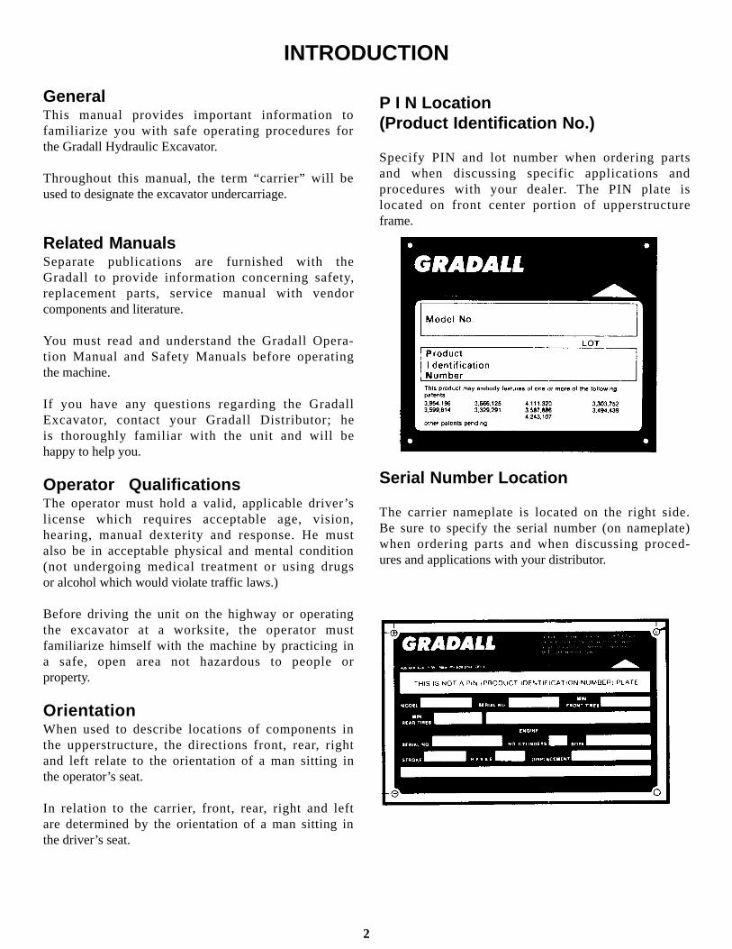
P I N Location(Product Identification No.)
Specify PIN and lot number when ordering partsand when discussing specific applications andprocedures with your dealer. The PIN plate islocated on front center portion of upperstructureframe.
Serial Number Location
The carrier nameplate is located on the right side.Be sure to specify the serial number (on nameplate)when ordering parts and when discussing proced-ures and applications with your distributor.
2

W A R N I N G
Maintain three point contact with grab handlesand steps when climbing on and off the machine.Never jump from the machine.
Repair or replace damaged steps and grabhandles.
Read and understand this manual, The Gradall Excavator SafetyManual, CIMA Safety Manuals and all instructional decals and platesbefore starting, operating or performing maintenance procedures onthis equipment. KEEP THIS MANUAL IN THE CAB.
Watch for these symbols; they are used
to call your attention to safety notices.
SAFETY HIGHLIGHTS
This symbol indicates an extreme hazard whichwould result in high probability of death orserious injury if proper precautions are nottaken.
This symbol indicates a hazard which couldresult in death or serious injury if properprecautions are not taken.
This symbol indicates a hazard which couldresult in injury or damage to equipment orproperty if proper precautions are not taken.
Perform all “CHECKS & SERVICES BEFORESTARTING ENGINE” and all “WARM-UP &OPERATIONAL CHECKS” at the beginning ofyour shift. Complete all required maintenance be-fore operating or driving the unit.
D A N G E R
C A U T I O N
W A R N I N G
3

Do not move carrier while low air light isglowing or while any auxiliary device is signal-ing a dangerous condition.
While in lower cab, the four wheel drivecan be engaged at any time in the lowerrange. Use low R.P.M.
1. Heater Control Knob 2. Defroster Switch 3. Heater Switch 4. Headlights Switch 5. Pump Engagement Light 6. Converter Oil Pressure Gage 7. Display Light Panel 8. Air Pressure Gage 9. Water Temperature Gage10. Transmission Shifter11. Volt Meter12. Oil Pressure Gage13. Tachometer14. Speedometer15. Hour Meter16. Converter Oil Temperature Gage
17. Fuel Gage18. Front Axle Disconnect (4x4 only)19. Ignition Key Switch20. Parking Brake Button21. Remote/Travel Switch22. Dome Light23. Windshield Wiper Speed Control24. Windshield Washer Switch25. Headlights Hi/Low Beam Switch26. Brake Pedal27. Acclerator Pedal28. Emergency Engine Shut Off29. Transmission Control Monitor30. Turn Signal Control Lever31. Hazard Flahser Switch32. Horn Button
4
CARRIER CAB CONTROLSINSTRUMENTS AND INDICATORS

UPPERSTRUCTURE CABCONTROLS AND INSTRUMENTS
1. Throttle Lever2. Boom In/Out & Swing Joystick3. Boom Tilt Switch4. Transmission Shift Up/Down Switch5. Horn Switch6. Boom Hoist & Bucket Joystick7. Joystick On/Off Switch8. Engine Stop Switch9. * Windshield Wiper/Washer Switch
10. Engine Start Switch11. Defroster Switch12. Warning Buzz Light13. Emergency Brake Knob14. Air Pressure Gage15. Forward/Reverse Travel Pedal16. Steering Pedal17. *Heater
*Optional
5
While working in upper cab, and any of the display panel warning lights go on inthe carrier cab, a buzzer will sound inboth cabs. The operator should placeboom in rack, shut engine off and go tolower cab and check all gauges anddetermine reason for warning. Correctmalfunction before continuing tooperate.

Left turn signal (A) flashes when lever on steeringpost is activated to indicate a left hand turn.(GREEN)
Remote Control Indicator (B) is lit when theremote rocker switch is depressed and all of thepre-conditions are met. It will turn RED. At thistime the remote drive motor should be engaged andthe digging brakes applied and upper throttleengaged.
If torque converter temperature reaches 250° F,(C) will light. (RED)If torque converter pressure drops below 200 psi,(D) will light. (RED)If head light switch is pulled and the foot button isdepressed, the high beam (E) will light. (BLUE)
The Monitor is located to the right of the driversseat in the carrier cab. The Controller Monitorprovides range selection of the solenoid controlledtransmission in both travel and remote modes. Italso determines if remote or travel mode has been
If air pressure drops below 60 psi, (F) will light.(RED). Check gauge.
If engine temperature reaches 210° F, (G) will light.(RED). Check gauge.
If engine oil pressure drops to approximately 15 psi,(H) will light. (RED). Check gauge.
If battery is below 12 volts, (J) will light. (RED)Right turn signal (K) flashes when the lever on thesteering post is activated to indicate a right handturn. (GREEN)
NOTE: If any of the warning lights C, D, F, G orH are on, a warning light and buzzer in theupper cab will be activated.
selected by the operator and controls the machinechangeover to the mode selected. The ControllerMonitor has a panel of 14 lights which shows thedriver the status of the control system.
Neutral Start Solenoid closedwhen lit.Travel alarms and back-up lightsenergized when lit.Low air condition exists when lit.Engine not running when lit.Hyd. Pump and Remote Motorengaged when lit.
Indicates a wire shorting betweenthe Controller Monitor and thetransmission shift solenoids. (WiresS1 through S6)
CARRIER CAB DISPLAY LIGHT PANEL
Neutral
Reverse
T1
T4
Malfunction
CARRIER CAB CONTROLLER MONITOR
Indicator
T2
Transmission Solenoid #1 ener- gized when lit. Transmission Solenoid #2 ener- gized when lit. Transmission Solenoid #3 ener- gized when lit. Transmission Solenoid #4 ener- gized when lit. Solenoid Air Valve shifted to travel mode when lit. Transmission Solenoid #5 ener- gized when lit. Transmission Solenoid #6 ener- gized when lit. Solenoid Air Valve shifted to remote mode when lit.
S1
S2
S3
S4
C1
S5
S6
C2
6

SHIFT SOLENOIDS. A combination of theselights tell which gear ratio has been selected. Theposition of the gear selector lever on the dashshould match. The following will show the lightcombinations while in the travel mode with high airand the key turned on and engine running: C1 is litto show the travel mode.
7
S1 C1 S6 - First Travel Gear
S1 C1 S5 - Second Travel Gear
S2 C1 S6 - Third Travel Gear
S2 C1 S5 - Fourth Travel Gear
S3 C1 S6 - Fifth Travel Gear
S3 C1 S5 - Sixth Travel Gear

C2-T4. The following lights are lit when the remotecontrol switch is depressed to show the gear ratiobeing used: The shift lever in the carrier cab will notmove. With engine running, and in remote,lights C-2, T4 and Neut Start will be lit. C2 isalways lit .
.
S1 C2 C3 & T4 - First Remote Gear
S2 C2 C3 & T4 - Second Remote Gear
S3 C2 C3 & T4 - Third Remote Gear
8
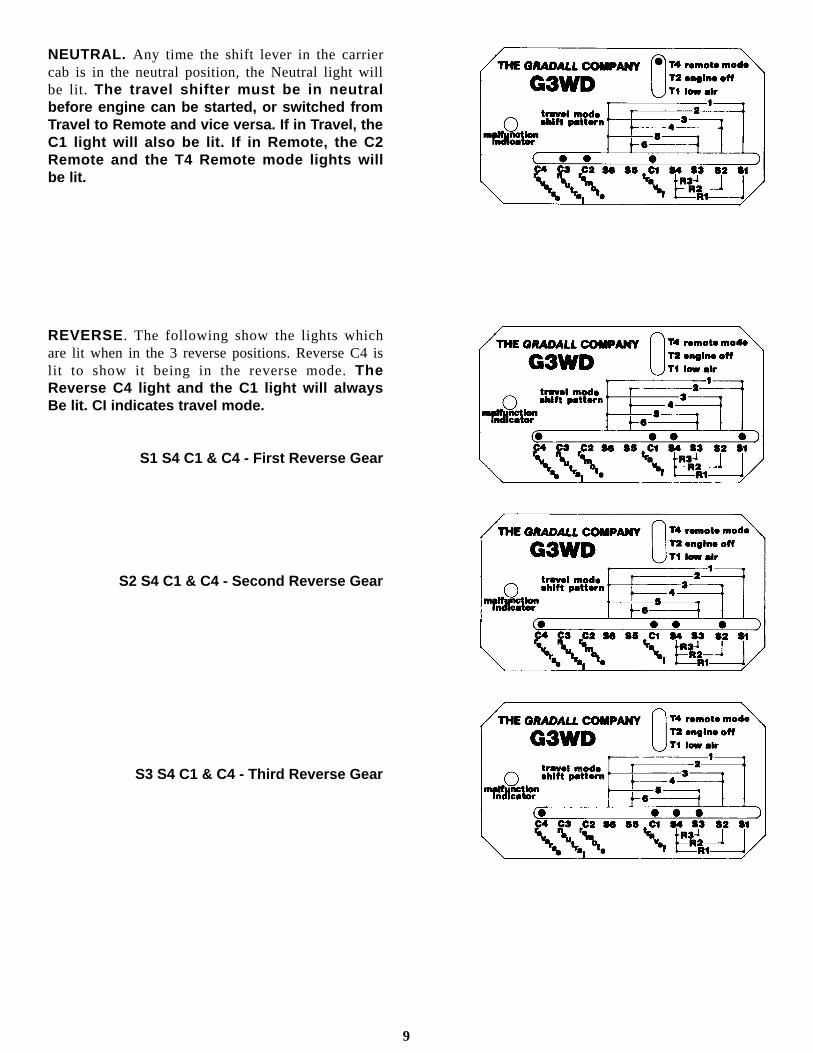
NEUTRAL. Any time the shift lever in the carriercab is in the neutral position, the Neutral light willbe lit. The travel shifter must be in neutralbefore engine can be started, or switched fromTravel to Remote and vice versa. If in Travel, theC1 light will also be lit. If in Remote, the C2Remote and the T4 Remote mode lights willbe lit.
REVERSE. The following show the lights whichare lit when in the 3 reverse positions. Reverse C4 islit to show it being in the reverse mode. TheReverse C4 light and the C1 light will alwaysBe lit. CI indicates travel mode.
S1 S4 C1 & C4 - First Reverse Gear
S2 S4 C1 & C4 - Second Reverse Gear
S3 S4 C1 & C4 - Third Reverse Gear
9
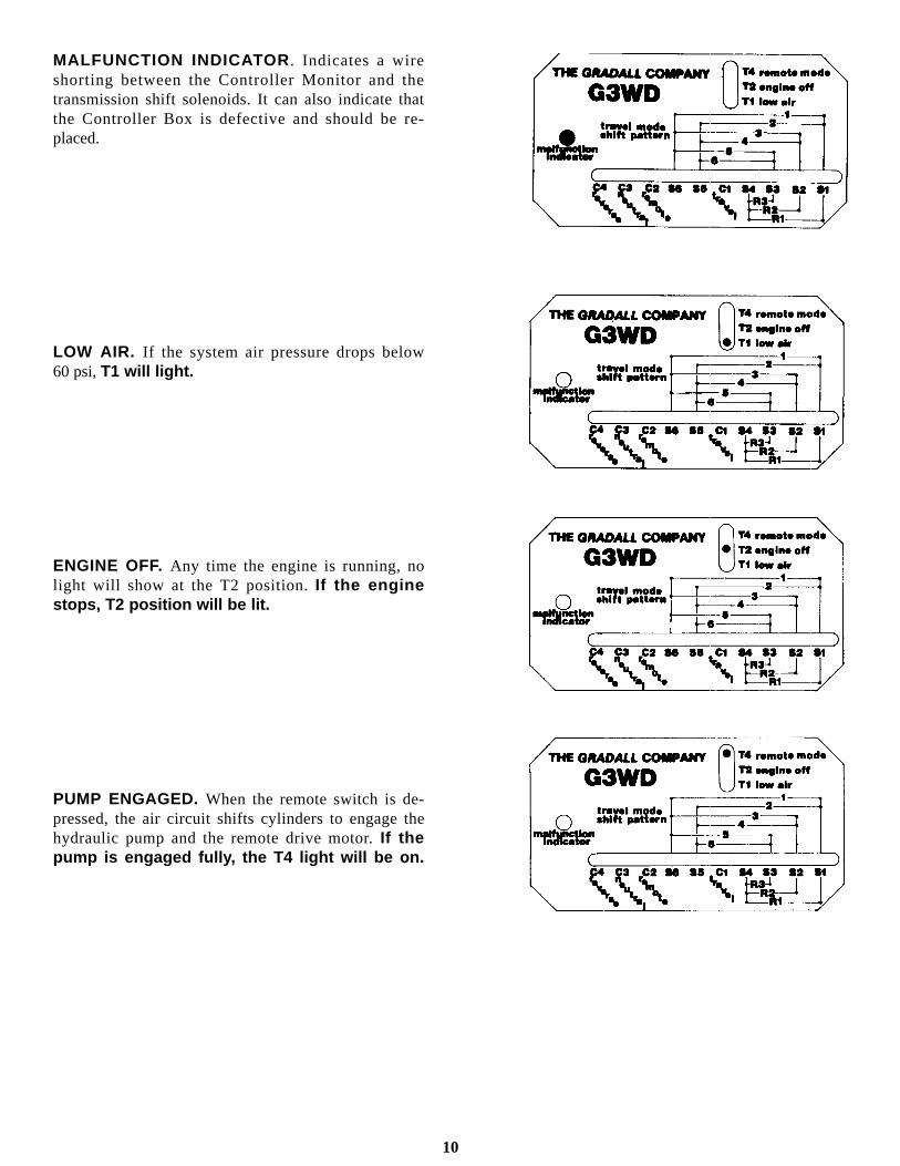
MALFUNCTION INDICATOR . Indicates a wireshorting between the Controller Monitor and thetransmission shift solenoids. It can also indicate thatthe Controller Box is defective and should be re-placed.
LOW AIR. If the system air pressure drops below60 psi, T1 will light.
ENGINE OFF. Any time the engine is running, nolight will show at the T2 position. If the enginestops, T2 position will be lit.
PUMP ENGAGED. When the remote switch is de-pressed, the air circuit shifts cylinders to engage thehydraulic pump and the remote drive motor. If thepump is engaged fully, the T4 light will be on.
10

Be sure main transmission is in neutral, parkingbrake is applied and engine stop handle is fullydepressed.
Depress accelator pedal to a fast idle and hold inthis position.
Turn ignition switch fully clockwise to engagestarting motor. Release key immediately whenengine starts. If engine fails to start within fifteenseconds, release key and allow starting motor tocool for a few minutes before trying again.
After engine starts, observe oil pressure gage. Ifgage remains on zero for more than ten seconds,stop engine and determine cause. Correct beforerestarting engine.
Operate engine at idle speed for a few minutesbefore turning it off. This allows engine coolantand lubricating oil to carry excessive heat awayfrom critical engine areas.
Starting Diesel Engine from Carrier Cab
Stopping the Engine from Carrier Cab
CHECKS AND SERVICEBEFORE STARTING ENGINE (To be performed at beginning of each work shift)
Complete all required maintenance before operating unit.
Inspect visually for damage, leaks, vandalism & needed maintenance.Test lights, turn signals, horn, & gages.Inspect battery fluid level.Make sure fire extinguisher is present.Inspect level of windshield washer fluid.Make sure remote switch is in travel position.Check coolant level.Check engine oil level.Check fuel level.Check for clean windows.Check hydraulic oil level.Lubricate as shown in manual.
1. 2. 3. 4. 5. 6. 7. 8. 9.10.11.12.
1.
2.
3.
4.
5.
11
Warm up diesel engines at approximately onethird of governed speed until water temperaturereaches operating range (approximately160°F./71°C).
NOTE: It may be necessary to use a cold weatherstarting aid in temperatures below freezing.
Do not engage starting motor while fly-wheel or starting motor is rotating. Seriousdamage could result.
Do not “gun” engine before shut down; thispractice causes raw fuel to remove oil film fromcylinder walls and dilute lubricant in crankcase.To stop diesel engine, turn key to off.

Cold weather starting aids
Start in travel mode (pump not operating).
Diesel engine ignition is accomplished by heatgenerated when fuel/air mixture is compressedwithin the cylinders. Because this heat may beinsufficient to start a cold engine in cold weather,the use of starting aids has become commonpractice.
Because of the wide variety of starting aids available
Normal engine operation
Observe voltmeter, water temperature and oilpressure gages frequently to be sure all enginesystems are functioning properly.
Be alert for unusual noises or vibration. Whenan unusual condition is noticed, stop in a safe areaand shut off engine. Determine cause and correctbefore continuing.
Early recognition and correction of unusual con-ditions can often prevent a major breakdown.
Apply load to engine gradually; shock loads arehard on all drive line components.
Use full governed engine speed for intermittentduty only. For cruising or continuous duty useapproximately 85 percent of full governed enginespeed to maintain safe speed. This practice providesincreased engine life.
it would be impractical to attempt to providespecific instructions for their use in this manual.Carefully follow instructions furnished with yourstarting aid.
If you use a starting aid employing ether or asimilar substance pay particular attention tomanufacturer’s warnings.
When using engine braking power (downshiftingor releasing accelerator and permitting carrier to“push” engine) to slow travel, take care to avoidoverspeeding the engine (exceeding governedRPM). The governor has no control over enginespeed when engine is being “pushed” by carrier load.
Select an appropriate gear ratio and use servicebrake to assist in slowing travel down steep grades.
Permitting the engine to labor under too great aload for the gear ratio being used (lugging theengine) will shorten engine life. Shift to the propergear ratio for conditions.
Avoid prolonged idling . Idling causes engine tem-perature to drop and this permits formation ofheavy carbon deposits and dilution of lubricating oilby incompletely burned fuel. If the engine is notbeing used, turn it off.
12

Check operation of windshield washer andwiper.
Check all lights and turn signals for properoperation.
Check operation of heater and defroster.
Observe oil pressure gage with engine runningat operating temperature and speed.
Observe voltmeter indication of alternator out-put. Proper output is approximately 14 V. withengine running at 2000 RPM.
Check operation of brakes by performing thefollowing procedure:
Position unit on level surface and applydigging brake.Position boom over rear of chassis and imbedbucket in ground or against a solid object.Apply down pressure with boom and pull andpush with boom while helper watches forrotation of each wheel.Rotation of any wheel during step c. indicatesbrake failure on that wheel. Have any failurecorrected before driving the unit.
Observe water temperature gage. Proper op-erating temperature is approximately 160/210° F. (71/104° C).
Observe tachometer response to changes inengine speed.
Observe low air warning light. Light shouldcontinue to glow until brake system pressurereaches approximately 60 psi. Do not releaseparking brake or move carrier while low airwarning light is still glowing.
Observe air pressure gages. Proper brakesystem pressure is 60/125 psi.
Check operation of steering while moving slowlyin first gear. Be alert for any increase in effortneeded to turn wheels and any unusual steeringresponse to normal steering effort.
Check operation of horn and travel and back-upalarm and any other signal devices.
CHECKS AFTER STARTING ENGINE(To be performed at beginning of each work shift)
Complete all required maintenance before driving
CHECKS BEFORE DRIVING
Complete all required maintenance before driving.
PLAN YOUR TRIP
a.
b.
c.
d.
1.
2.
3.
4.
5.
6.
7.
8.
9..
(To be performed at beginning of each work shift)
2.
3.
Plan a safe route to your destination.Ask your supervisor about permit requirements.Check on load & clearance limits along your route.Dimensions for your unit are shown below:Height - varies depending on attachment measure unit to be sure.Width (4 x 2). . . . 8'(2.44 m). . . . . . . . . . . . . . . . . . . . 100" on 4 x 4Ground Clearance . . . . . . . . . . . . . . . . . . . . . . . . . . . . 10" (254 mm)Weight - varies depending on options weigh unit to be sure.—
—
1.2.3.
13
1.

AIR CONTROLS
Air pressure is used to control the engine RPMwhile driving the chassis or while operating the up-perstructure.
To keep the pump and remote drive motor disen-gaged while driving the carrier, air cylinders areused to actuate jaw type clutches. When the remotetoggle switch button on the dash is depressed, air
shifts the cylinders at the pump and motor to causethe jaw clutches to close and engage the pump andmotor.
A limit switch is placed by the pump engage cylinderto provide a visual warning light if the desired strokeis not obtained and the pump does not fully engagefor upperstructure operation.
14

Conventional Driving Mode:
When driving the carrier, the floorboard acceler-ator is used to control the engine speeds from idle totop governed RPM. The low idle is about 600 RPMand the top is about 3l50 RPM (No Load) or 2800RPM (Loaded).
When starting the engine with low air, the spring onthe fast idle cylinder (1) works on the governor link-age to obtain a higher than idle speed to help buildup air pressure quickly. When the system builds upto 55 psi, the piston in the fast idle cylinder moves tocounter the spring tension and the engine will run atnormal low idle speed.
Normal depressing of the Accelerator Pedal (2)routes air from the tank (3), thru the Air Pilot Valve(4), thru a Shuttle Valve (5), to the Throttle Cylinder(6). Movement of the piston in the throttle cylindermoves the Fast Idle Cylinder and the linkage to theengine governor (7). RPM is determined by theamount of travel caused by pushing down on thetreadle valve pedal.
AIR THROTTLE CONTROL CIRCUIT
Remote Control Driving Mode:
When driving the carrier from the upperstructure inthe remote control mode a hand controlled air valveis used (8). It is located on the cab floor to the left ofthe operator’s seat. While in remote a low idle of 600RPM and a high idle of 2700 RPM (No Load) or2300 RPM (Loaded) can be obtained.
The remote air circuit is activated when the remotecontrol switch (9) is depressed. Electrical current ac-tivates the Air Control Solenoid (10), routing tankair over to the control port of the Air Pilot Valve (4).Air pressure causes the Air Pilot Valve (4) to shift,routing air to the upperstructure circuits thru cen-terpin (11) and the Hand Throttle Valve (8). Whenthe hand throttle is moved, controlled air is routedback down thru the centerpin (11) and thru theShuttle Valve (5) to the Throttle Cylinder (6).
It is possible to control the engine RPM from thecarrier cab or the upperstructure cab.
15
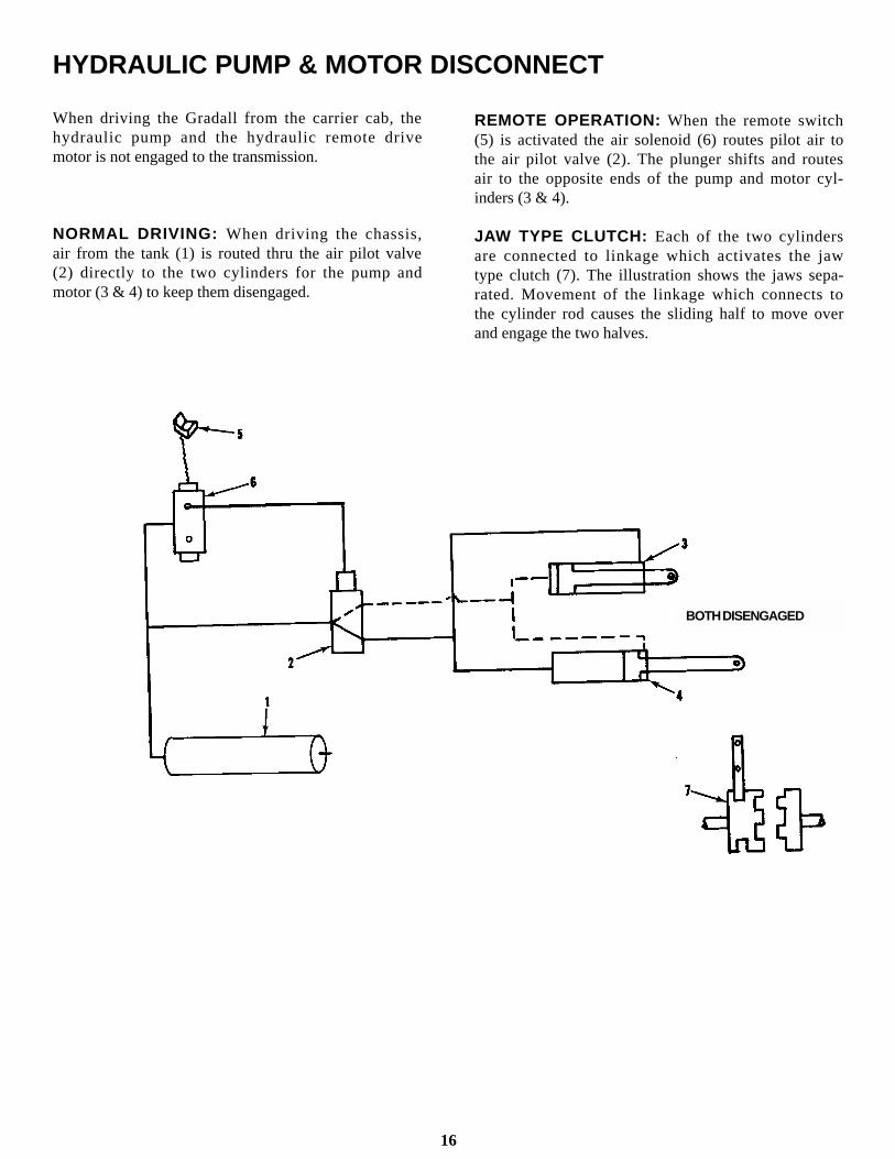
When driving the Gradall from the carrier cab, thehydraulic pump and the hydraulic remote drivemotor is not engaged to the transmission.
NORMAL DRIVING: When driving the chassis,air from the tank (1) is routed thru the air pilot valve(2) directly to the two cylinders for the pump andmotor (3 & 4) to keep them disengaged.
HYDRAULIC PUMP & MOTOR DISCONNECT
REMOTE OPERATION: When the remote switch(5) is activated the air solenoid (6) routes pilot air tothe air pilot valve (2). The plunger shifts and routesair to the opposite ends of the pump and motor cyl-inders (3 & 4).
JAW TYPE CLUTCH: Each of the two cylindersare connected to linkage which activates the jawtype clutch (7). The illustration shows the jaws sepa-rated. Movement of the linkage which connects tothe cylinder rod causes the sliding half to move overand engage the two halves.
16
BOTH DISENGAGED

The air brake system includes a service brake, anemergency brake, a parking brake and a diggingbrake.
Wear safety belt to avoid being thrownfrom carrier driver’s seat during brakingemergency.
Service brake
The basic system includes two reservoirs to storeand furnish air pressure for service brake operation.One reservoir supplies pressure to apply brakes tothe wheels of the front axle and the other suppliespressure to apply brakes to the wheels of the rearaxle. Depressing the brake treadle causes air pres-sure to be applied to brake actuators of all wheelssimultaneously.
Do not “fan” the brake valve treadle. A longseries of rapid brake applications canreduce system pressure to a point whereeffective service braking will be lost untilair compressor can restore pressure.
Operating pressure range for service brakes is 60 to125 psi. A dual pressure gage is furnished to indi-cate pressure in front and rear portions of brakesystem. The red needle shows pressure available forrear axle brakes and the green needle shows pressureavailable for front axle brakes. If pressure in eitherportion of the system falls below safe operatingrange, the low air indicator light will glow.wheels of the front axle.
BRAKE SYSTEM
Do not operate carrier while low air indicatoris glowing. If light comes on while carrier ismoving, stop carrier in a safe area as soon aspossible. If carrier will not maintain properbrake pressure notify maintenance personnelimmediately for repair of condition.
Emergency brake
The emergency brake functions only when airpressure has been lost from some portion of the dualbrake system. Emergency brakes are applied bynormal foot pressure on the brake treadle.
Emergency brakes will not stop carrier inas short a distance as the service brakes.
EMERGENCY BRAKE
APPLICATION(pressure lost in front)
If air pressure is lost from the front portion of thedual brake system, normal actuation of the braketreadle valve will apply service brakes to the wheelsof the rear axle. There will be no braking on the
WARNING
SERVICE BRAKEAPPLICATION
17

BRAKE SYSTEM (Con’t.)
EMERGENCY BRAKEAPPLICATION
(pressure lost in rear)
If the air pressure is lost from the rear portion of thedual brake system, normal actuation of the braketreadle will apply service brakes to the wheels of thefront axle and cause a controlled application ofspring brakes to the wheels of the rear axle.
After pressure is lost from one portion of the dualbrake system, there may only be enough pressure inthe other portion for one or two emergency brakeapplications. When the available pressure has beenused the spring brakes will apply automatically.
EMERGENCY BRAKEAPPLICATION
(pressure lost in front and rear)
AUTOMATIC
In the event air pressure is lost from both front andrear portions of the system there will be anautomatic application of the spring brakes. Theywill begin to apply as pressure drops to 60 p.s.i. (414kPa) and there will be a complete application whenpressure decreases to 40 p.s.i. (276 kPa).
Because air pressure is required to release springbrakes, an automatic application will remain ONuntil air pressure can be restored.
If the air pressure gages indicate some systempressure remaining, it may be possible to drive theunit a short distance to remove it from a hazardousposition (use first gear only).
If carrier cannot be moved, direct traffic aroundcarrier until warning flags, flares or lights can bedisplayed. Notify proper authorities andmaintenance personnel as soon as possible.
Parking brake
Apply parking brake by raising parking brakecontrol knob. This causes air pressure to be ventedfrom spring chambers allowing springs to applybrakes to wheels of the rear axle. Knob will raiseautomatically if air pressure is lost from front andrear portions of system.
PARKING BRAKEAPPLICATION
Release parking brake by depressing parking brakecontrol knob (system must be pressurized to releaseparking brake).
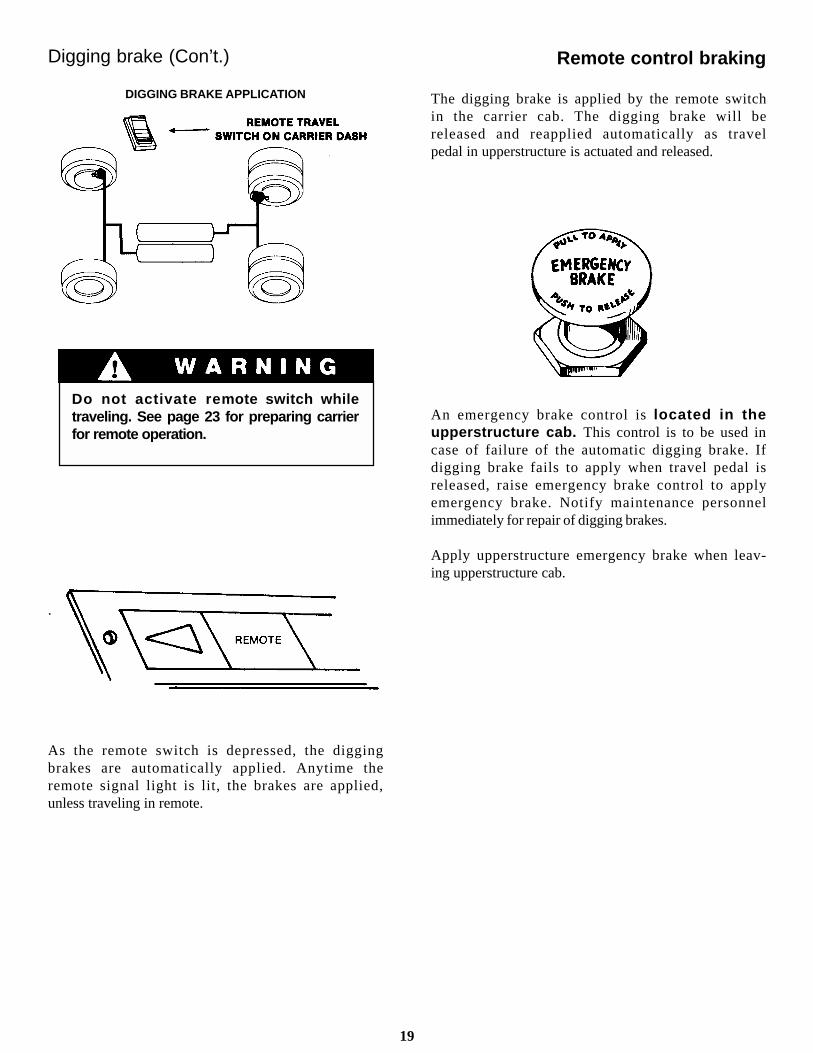
Digging brake
When activated, the digging brake is applied to allwheels to hold the carrier stationary while theexcavator is digging.
Air pressure requirements for digging brakeapplication are not the same as those for the servicebrake (60 to 85 p.s.i. - 414 to 586 kPa). If pressureis lost after the digging brake has been applied,emergency brakes will be applied automatically.
18
Digging brake (Con’t.)
DIGGING BRAKE APPLICATION
Do not activate re mote switch whiletraveling. See page 23 for preparing carrierfor remote operation.
.
As the remote switch is depressed, the diggingbrakes are automatically applied. Anytime theremote signal light is lit, the brakes are applied,unless traveling in remote.
The digging brake is applied by the remote switchin the carrier cab. The digging brake will bereleased and reapplied automatically as travelpedal in upperstructure is actuated and released.
An emergency brake control is located in theupperstructure cab. This control is to be used incase of failure of the automatic digging brake. Ifdigging brake fails to apply when travel pedal isreleased, raise emergency brake control to applyemergency brake. Notify maintenance personnelimmediately for repair of digging brakes.
Apply upperstructure emergency brake when leav-ing upperstructure cab.
Remote control braking
19
STEERING SYSTEM
Conventional steering
The power steering system provides low effortsteering under normal conditions and greatercontrol in the event of a blowout or soft ground.“Road feel” is similar to that of a conventionalmanual steering system.
Use of power steering while carrier isstopped causes unnecessary stress onsystem components and can causeserious damage to system.
Holding steering wheel in full left turn orfull right turn position will cause system tooverheat. This can cause steering pump to fail.
Remote control steering
Your unit is equipped with a travel/steering pedalin the upperstructure cab. The engine must berunning to provide power for remote controlsteering.
Regardless of upperstructure position on carrier,depressing left side of pedal turns wheels to left;depressing right side of pedal turns wheels to right.
When not held in a left or right steering position,the steering pedal will return automatically to itsneutral (non-steering) position. Be sure upper-structure cab is kept free of equipment and foreignmaterial which could jam steering pedal in asteering position.
Rotation of the carrier steering wheel will occurduring remote operation. KEEP CLEAR!
Be alert for any increase in effort needed tosteer. If any difference is noted, notifymaintenance personnel immediately forcorrection. If power assist feature shouldfail for any reason IT WOULD BECOMEVERY DIFFICULT TO STEER. For thisreason it is extremely important that youNEVER TURN ENGINE OFF WHILETRAVELING.
In the event power steering fails, stop assoon as possible. Do not drive unit untilproblem has been corrected.
20
The power train furnished on 4 x 2 carriers (unitshaving one driving axle at rear) include the engine,torque converter, power shift transmission and therear axle. It includes the drive shaft between thetransmission and the rear axle.
Torque ConverterThere are no operator controls for the torqueconverter. It functions automatically to permitstarting from a standstill in any transmission speedrange.
The Series 2000 Shift-O-Matic is a six speedforward, three speed reverse transmission.
Forward motion, reverse motion, and the speedsare obtained through the use of electricallycontrolled solenoids and hydraulically actuatedmultiple disc clutches. These clutches are powerabsorbing members that can be engaged at fullengine power. Shifting under full engine powermakes this a full power shift for the forward andreverse motion in all speeds.
The clutches in these units are hydraulicallyapplied and spring released. Because the clutchesare hydraulically controlled, there is automaticcompensation for normal wear, which eliminatesthe need for adjustment. Each clutch uses acomposition friction plate and a polished steelreaction plate.
The power train furnished on 4 x 4 carriers (units havingboth front and rear driving axles) include theengine, torque converter, power shift transmissionand the front and rear driving axles. Thetransmission is moved back to the center portion ofthe frame and drive shafts are used to connect it withthe engine and the two axles.
Torque converter oil temperature and oil pressuregages are provided to monitor torque converteroperation.
The power from the engine is transmitted to theShift-O-Matic through a torque converter. The useof the torque converter has two distinctadvantages; (1) the converter is essentially a fluiddrive, there being no direct mechanical connectionbetween the engine and transmission assembly.This feature creates a very smooth and shock-freedrive eliminating engine stalling. (2) The convertermultiplies torque during heavy pull-down loads.When loads are light, the converter transmits theengine power directly at almost engine speed, andthere is no torque multiplication. The net result isan action like a transmission, with infinitelyvariable and automatic speed ratios. The need forshifting gears, although present, is greatly reduced.
POWER TRAIN
POWER SHIFT TRANSMISSION
21
Downshifting
During normal driving there are times when it isnecessary to downshift (shift from one gear or rangeto the next lower gear or range) to decrease carrierspeed or increase carrier power. The procedure fordownshifting is described below.
When to shift gears
Smooth timely shifting not only increases carrierservice life, it provides greater driving safety.
In lower gears use only enough engine speed to getthe carrier rolling easily. High engine speeds underlight load conditions waste fuel and cause excessiveand unnecessary noise. Use a little more enginespeed for each successive upshift until reachingdesired cruising speed.
Avoid continuous operation at full governed engineRPM. Cruising at governed RPM reduces engineservice life and provides no reserve power forvarying conditions. It is good practice to select agear offering desired carrier speed atapproximately 85 percent of governed engine speed.Reserve full governed RPM for conditionsrequiring full power.
KEEP CARRIER IN GEAR WHILE DRIVING; COASTING ISDANGEROUS AND MAY CAUSE SERIOUS DAMAGE TO TRANSMISSION.
Never downshift when carrier speed willcause engine to overspeed in next lowergear or serious damage to engine mayresult. Use service brake to slow carrier toproper speed for downshift if necessary.
When load conditions cause a continuing loss ofengine speed, downshift to the next lower gear.
In general, operate in a gear that will permitacceleration.
Though it is permissible to use the braking power ofthe engine when traveling downhill take care toavoid overspeeding the engine (exceeding governedRPM). The governor has no control over enginespeed when the engine is being pushed by the carrierload. Select an appropriate gear ratio and use yourbrakes to assist in slowing the carrier.
22

When the driver wants to stop the Gradall on the joband operate the upperstructure, he switches to re-mote control of the carrier at the same time. Thefollowing steps are taken:
1. Stop the machine.2. Set the parking brakes.3. Place the transmission shifter in neutral.4. Turn the engine off.5. Turn the key on again, but don’t start engine.
Be sure controls in carrier cab have beenproperly set for remote control operation(above).
Be sure travel and steering pedals are in neutralposition.
REMOTE CONTROLS IN UPPERSTRUCTURE
REMOTE CONTROL
NOTE: Remote control is to be used for positioning unit atjob site, not for over-the-road travel.
Preparing Carrier for Remote Control Operation
Actuate the remote control switch.A. A remote indicator will go on.B. The controller lights will show air is OK.C. The pump and drive motor are engaged.D. The brakes are set.E. The transmission shifts automatically intofirst gear.Release the parking brake button.Turn key to on position. Engine will not startuntil pump engagement light is off.
An air controlled throttle is provided to bring theengine RPM up to full governed RPM for upper-structure operation.
Be sure EMERGENCY BRAKE control is inOFF position.
How to Start Engine fromUpper Cab.1. Start engine by depressing green start button.
Preparing Upperstructure for Remote Control Operation
1.
2.
3.
4.
6.
7.8.
23

Be sure of clear visibility in direction of travel;use a signalman to compensate for blind spots.
Be sure upperstructure swing brake functionsproperly before moving carrier in remotecontrol.
Be sure of clear path for carrier, boom andcounterweight before starting to move. Beespecially watchful for overhead wirestraffic.
Be sure controls in carrier and upperstructurecabs have been properly set for remote controloperation (see previous page).
Be sure engine is running at full throttle. Carrierspeed is controlled by gear selection and amountof pedal actuation.
The travel pedal controls carrier travel; depressfront of pedal to travel forward or rear of pedal totravel in reverse. The digging brake is auto-matically released when the pedal is depressedand applied when the pedal is released. Pedal
Shifting Gears While in Remote Control
It is possible to shift into your choice of the threelower gear ranges while operating in remote controlfrom the upperstructure.
A rocker switch is provided on the joystick pedestal.Pressing down one time on the front of the rockerwill advance the shifter one gear higher. Press itagain and it will shift into third gear.
Pressing down on the rear of the shifter rockerswitch will reverse the action and shift down onegear at a time.
The shifting of these three gears can be done whilethe machine is moving.
Precautions for Remote Control Operation
Never tow load using remote control drive.
Always give audible signal before moving unit.
Never permit bucket to drag while moving unit.
Rotation of carrier steering wheel will occurduring remote operation. KEEP CLEAR!
Be sure travel alarm functions properly.
Front Axle Lock Cylinders AutomaticallyUnlock in Travel.
returns to neutral position when released.Release pedal gently for a smooth stop.
The steering pedal controls right and left turns;depress left side of pedal to turn left or right sideof pedal to turn right. Pedal returns to neutralposition when released.
Use EMERGENCY BRAKE to stop carrier ifautomatic digging brake fails. Lift control knobto apply brakes. Brakes cannot be released untilpressure is restored and parking and emergencybrake control knobs are depressed.
Apply emergency brake beforeleaving upper cab.
Avoid confusion! Before actuating remote control travel pedal, think aboutthe direction you are facing with respect to the direction the carrier isfacing. Confusion could cause you to travel in the direction opposite that
Driving carrier from upperstructure cab
4.
5.
1.
2.
3.
24

Allow engine to cool by running at idle speed fora few minutes. Stop engine.
Be sure travel and steering pedals are in neutralposition.
Move the remote switch to the travel position.This release the remote brakes, disengages thehydraulic pump and the drive motor.
chine with boom in air.
Park on level ground and block wheels.
If parking on a slope cannot be avoided, posi-tion unit at right angle to slope and blockwheels.
Block carrier wheels as extra precautions againstrolling.
Fill fuel tank to minimize condensation. Removeignition key.
Lock carrier and upperstructure cabs and installprotective window covers if available.
Disconnect batteries if unit is in an area wheretampering seems possible.
Preparing Upperstructure for Conventional Carrier Operation
Test brakes (refer to page 11).
Retract boom and position boom in boom rest.Secure boom using boom hold-down device asnecessary.
Raise brake control knob to apply emergencybrake.
Shift main transmission to neutral.
Apply parking brake.
Precautions:
Avoid parking on slopes or near an excavation.
Avoid parking on roads or highways. If It can-not be avoided be sure to display warning flagsduring day and flares or flashing lights at night.
Position boom in boom rest; never leave ma-
Parking procedure
Using service brake, stop unit in appropriateparking area.
Set PARKING BRAKE to ON.
Allow engine to cool at idle speed for a fewminutes and then turn off.
Shift transmission to first gear.
Preparing Carrier for Conventional Operation
PARKING THE GRADALL
IN CASE OF TROUBLE
1. Park unit in a safe area, apply parking brake and block wheels. Display warning flags, flares or flashing lights as necessary.
2. Contact supervisor and advise:Nature of problem
Location of unit Where you can be reached by phone
2525252525
1.
2.
3.
1.
2.
1.
2.
3.
4.
4.
5.
3.
5.
6.
7.
8.
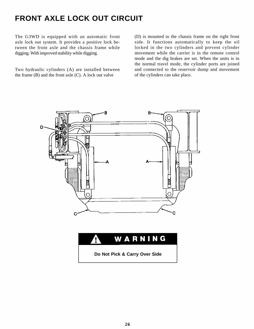
The G3WD is equipped with an automatic frontaxle lock out system. It provides a positive lock be-tween the front axle and the chassis frame whiledigging. With improved stability while digging.
Two hydraulic cylinders (A) are installed betweenthe frame (B) and the front axle (C). A lock out valve
(D) is mounted to the chassis frame on the right frontside. It functions automatically to keep the oillocked in the two cylinders and prevent cylindermovement while the carrier is in the remote controlmode and the dig brakes are set. When the units is inthe normal travel mode, the cylinder ports are joinedand connected to the reservoir dump and movementof the cylinders can take place.
FRONT AXLE LOCK OUT CIRCUIT
Do Not Pick & Carry Over Side
26
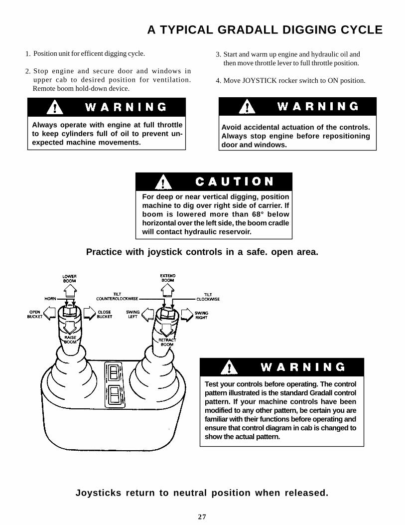
Position unit for efficent digging cycle.
Stop engine and secure door and windows inupper cab to desired position for ventilation.
Remote boom hold-down device.
A TYPICAL GRADALL DIGGING CYCLE
Always operate with engine at full throttleto keep cylinders full of oil to prevent un-expected machine movements.
For deep or near vertical digging, positionmachine to dig over right side of carrier. Ifboom is lowered more than 68° belowhorizontal over the left side, the boom cradlewill contact hydraulic reservoir.
Start and warm up engine and hydraulic oil andthen move throttle lever to full throttle position.
Move JOYSTICK rocker switch to ON position.
3.
4.
1.
2.
Avoid accidental actuation of the controls.Always stop engine before repositioningdoor and windows.
Test your controls before operating. The controlpattern illustrated is the standard Gradall controlpattern. If your machine controls have beenmodified to any other pattern, be certain you arefamiliar with their functions before operating andensure that control diagram in cab is changed toshow the actual pattern.
27
Practice with joystick controls in a safe. open area.
Joysticks return to neutral position when released.

A TYPICAL GRADALL DIGGING CYCLE
Move right joystick to left (G) to swing left or toright (H) to swing right to digging site.
Move left joystick to left (C) to open bucket or toright (D) to close bucket for correct penetration.Teeth should angle downward slightly (about(5°). Angle may be greater for soft digging.
Pull back on left joystick (A) to raise boom fromboom rest. Be sure to raise boom far enough toclear all obstructions.
While pushing right joystick forward (F) toextend boom, push left joystick forward (B) tolower boom to position for start of cut.
5.
7.
6.
8.
28
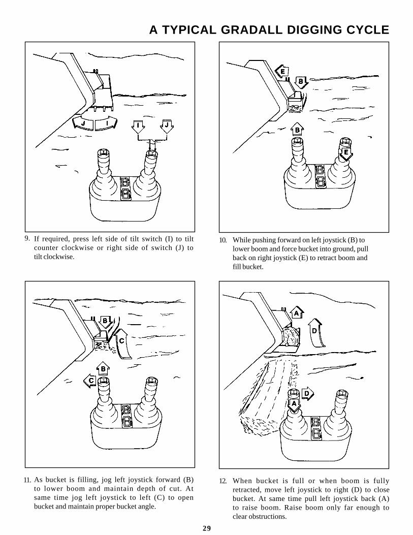
If required, press left side of tilt switch (I) to tiltcounter clockwise or right side of switch (J) totilt clockwise.
As bucket is filling, jog left joystick forward (B)to lower boom and maintain depth of cut. Atsame time jog left joystick to left (C) to openbucket and maintain proper bucket angle.
A TYPICAL GRADALL DIGGING CYCLE
While pushing forward on left joystick (B) tolower boom and force bucket into ground, pullback on right joystick (E) to retract boom andfill bucket.
When bucket is full or when boom is fullyretracted, move left joystick to right (D) to closebucket. At same time pull left joystick back (A)to raise boom. Raise boom only far enough toclear obstructions.
9.
11.
10.
12.
29

Move left joystick to left (C) to empty thebucket.
A TYPICAL GRADALL DIGGING CYCLE
Move right joystick to right (H) to swing rightor to left (G) to swing left to dump site. Ifnecessary, extend boom by pushing rightjoystick forward (F).
Move right joystick to left (G) or right (H) toalign boom for next cut. Repeat steps 7 thru 15.
13. 14.
15.
30

Precautions
Do not depend on machine tipping as a warning ofoverload. Some load ratings are based on hydrauliclift capacity, not stability.
Hydraulic relief settings must be correct when liftingand positioning loads.
Suspend loads only as shown. Passing load line overbucket can cause uncontrolled movement of load.
Always operate at full engine RPM when handling aload. This keeps cylinders filled and preventsunexpected machine movements.
Keep everyone clear of machine (especially theboom and suspended load). Use guide ropes toposition load.
Lock out cylinders automatically unlockin travel.
Load Attachment Point
With bucket/adapter resting on ground, positionhook in tool eye as shown. Open bucket/adapter farenough to prevent accidental disengagement ofhook. Be sure hook is not too large to fit betweentool eye and adapter.
SECURING BOOM/BUCKETFOR TRAVEL
Position boom in boom rest and secure with boomtie-down.
LIFTING AND POSITIONING A LOAD
Do not travel with a suspended load. Excava-tors are not designed for pick and carry lifts.
Sudden swing braking can cause unexpectedmovement of the load and tip the machine.
Be sure tires are properly inflated before handling aload.
Keep load line vertical. Side loads can causestructural damage and tip the machine.
Do not lift a load if unit has a boom extensionattached.
Be thoroughly familiar with excavator hand signals(shown at end of manual).
Never pass load line over bucket. Relief valves inbucket circuit could cause unexpected, dangerousmovement of the load. Bucket linkage could also bedamaged.
31

General
The excavator can lift and position loads safelyONLY IF YOU PLAN THE LIFT PROPERLY.
There is a great lift capacity difference between theexcavator ’s best and worst lift positions. Justbecause it can lift a load from one point does notmean it can safely move the load to any other point.
For example, the best lifting position is with theexcavator level and the boom fully retracted andhorizontal. Assume that you have just lifted themaximum rated load from a truck with the unit inthis position. You can swing, but the only otherthing you can safely do with the load is put it backon the truck. Lowering, or extending the boom canexceed the rated capacity of the unit.
The “common sense” and “feel” an experiencedoperator might apply in regard to “tipping loads”DOES NOT APPLY to loads limited) by hydrauliclift capacity. Some loads shown on the chart in cabare Hydraulic Lift Capacities. Exceeding thesecapacities can cause a relief valve to open allowingthe load to fall, or in some cases, the machine to tip.
To avoid exceeding capacities, the entire lift must beplanned.
Positioning Machine For A LiftBefore discussing the steps in planning a lift, let’sconsider the most favorable excavator positions formaking a lift.
The shorter the load radius the greater the liftcapacity. Position the unit to minimize boomextension while keeping a safe distance fromobstructions and excavations.
Position the unit to minimize boom travel aboveand below horizontal. For example, it may benecessary to use a short sling to move a load froma truck to the ground. Then use a longer sling toposition load in an excavation.
Finally, position unit for maximum visibility. Ifconditions do not permit a clear view of the loadthrough entire lift, use a signal man.
Planning A Lift
Determine the weight of the load. Weight ofslings, chains and auxiliary lifting devices mustbe added as part of the load. Refer to lift capacitychart for weight adjustment required for bucket.
NOTE: Lift capacities are based on machine beingon a firm level surface and also on load being freelysuspended as shown.
Move the machine to the best probable positionfor making the lift.
Perform an unloaded trial run of the lift todetermine maximum load radius required andmaximum boom height and depth required tocomplete the lift.
Measure load radius from the center of the rear axleto the vertical load line and add 34" (distance fromaxle to center of rotation).
Measuring Load Radius
Measure boom height/depth from bucket adapterpivot shaft to ground level (same plane as bottom oftires). Be sure to allow for length of sling and heightof load.
Refer to lift capacity chart column for therequired load radius. If the required radius fallsbetween columns, use the column for the nextlarger radius.
Check the appropriate capacities for the requiredboom height and depth. The smaller of thesecapacities is the maximum load permitted for liftconditions.
To determine practical working load limits theoperator must also consider wind, hazardousconditions, experience of personnel and properload handling.
Failure to plan a lift properly can causedeath or serious injury.
Keep tires properly inflated. You havemore stability over the rear and less overthe side.
1.
2.
3.
4.
5.
32
Start engine. Position the upperstructure withthe boom over the right or left side of thecarrier. Extend the telescopic boom four feet andplace the bucket edge LEVEL into the ground.Stop the engine.
Using a 1-1/2" wrench, remove the four 1" capscrews from the stop blocks.
On the left side of the boom, loosen the four1" capscrews which hold the two boommounting brackets. (These bolts shouldbe loosened as far as possible withoutremoving them.)
Lubricate slide areas of boom, if needed.
Start the engine in the upper cab, and engagethe off-on switch activating the joysticks.Make sure bucket is level and wedged into theground. Pull back on the boom in-out joystick.The boom should start sliding. Continue slidingthe boom until contact is made against the rearstop blocks. Stop the engine.
.Place the four 1" cap screws removed from thefront stop blocks into the rear stop blocks.Tighten these four cap screws.
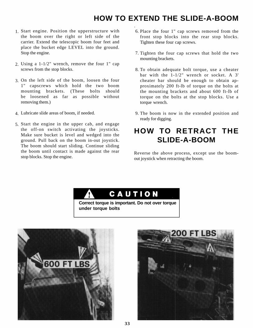
Tighten the four cap screws that hold the twomounting brackets.
To obtain adequate bolt torque, use a cheaterbar with the 1-1/2" wrench or socket. A 3'cheater bar should be enough to obtain ap-proximately 200 ft-lb of torque on the bolts atthe mounting brackets and about 600 ft-lb oftorque on the bolts at the stop blocks. Use atorque wrench.
The boom is now in the extended position andready for digging.
HOW TO RETRACT THESLIDE-A-BOOM
Reverse the above process, except use the boom-out joystick when retracting the boom.
HOW TO EXTEND THE SLIDE-A-BOOM
Correct torque is important. Do not over torqueunder torque bolts
33
1.
2.
3.
4.
5.
6.
7.
8.
9.

Position bucket adapter above bucket tube asshown and lower boom until concave section ofadapter contacts bucket tube.
Install adapter wedge bolts, washers and nuts andtighten finger tight.
Position bucket linkage as desired.
ATTACHMENT INSTALLATION
Keep boom in fully extended positionwhile installing bucket. Stay clear untilbucket adapter has been fitted tobucket asshown in step 2.
Move adapter toward “Bucket Close” positionuntil outer end of adapter contacts bucket.
Raise boom slightly until bucket just clearsground and tighten nuts. Check often to be surenuts remain tight.
Check to be sure bucket travel is limited by stopswhen opening and by bucket tube when closing- NOT by cylinder bottoming.
Never fully extend bucket cylinder withouta bucket ins talled or cylinder rod will bedamaged.
Digging with a loose or an improperlyfitted bucket can shear adapter bolts andcause excessive wear.
34
1.
3.
5.
2.
4.
6.

EXCAVATOR HAND SIGNALS
Standard Signals - When excavator work conditionsrequire hand signals, they shall be provided orposted conspicuously for the use of both signalmanand operator. No excavator motions shall be madeunless signals are clearly understood by bothsignalman and operator.
Spccial Signals - When signals for auxiliaryequipment functions or conditions not covered arerequired, they shall be agreed upon in advance bythe operator and signalman.
Instructions - When it is desired to give instructionsto the operator other than provided by theestablished signal system, all excavator motionsshall first be stopped.
MOVE LOAD IN HORIZONTALLY - With either armextended, hand raised and open toward direction ofmovement, move hand in direction of requiredmovement.
LOWER BOOM - With either arm extended horizon-tally, fingers closed, point thumb downward.
SWING - With either arm extended horizontally,point with forefinger to direction of swing rotation.
LOWER LOAD VERTICALLY - With either armextended downward, forefinger pointing down,move hand in small horizontal circle.
RAISE BOOM - With eitherarm extended horizon-tally, fingers closed, point thumb upward.
RETRACT TELESCOPIC BOOM - With both handsclenched, point thumbs inward,
OPEN BUCKET - Hold one hand oen and staion-ary. Rotate other hand in small vertical circle withforefinger pointing horizontally at open hand.
RAISE LOAD VERTICALLY - With either forearmvertical, forefinger pointing up, move hand in smallhorizontal circle.
MOVE LOAD OUT HORIZONTALLY - With eitherarm extended, hand raised and open towarddirection of movement, move hand in direction ofmovement.
EXTEND TELESCOPIC BOOM - With both handsclenched, point thumbs outward.
SWING - With either arm extended horizontally,point with forefinger to direction of swing rotation.
35

rear to prevent tipping) and imbed bucket in ground.
While actuating travel joystick in appropriate di-rection, extend or retract boom as required to helppush or pull unit to solid ground. Raise or lowerboom as necessary to keep rear wheels in propercontact with ground.
IF YOU GET STUCK
If unit becomes stuck in soft ground you can use theboom to help free it.
Position carrier and upperstructure controls forremote control operation.
Position boom over rear of carrier (centered over
STOP ENGINE - Draw thumb or forefinger acrossthroat.
CLOSE RUCKET - Hold one hand closed andstationary. Rotate other hand in small vertical circlewith forefinger pointing horizontally at closed hand.
MOVE SLOWLY - Place one hand motionless infront of hand giving motion signal. (Raise loadslowly is shown.)
THIS FAR TO GO - With hands raised and openinward, move hands laterally, indicating distance togo.
EMERGENCY STOP - With both armsextendedlaterally, hands open downward, move arms backand forth.
STOP - With either arm extended laterally, handopen downward, move arm back and forth.
36

G3WD GRADALL