Embed Size (px)
Citation preview

Sterling/Great Bend Mid-Mount Loader
Complete the “Delivery / Warranty Registration Card” This Manual must be delivered
To the Owner at time Of Machine Delivery. Read and Save This Manual
OPERATOR INSTALLATION & PARTS MANUAL
KMW Ltd. 198 N. Hwy 281
Great Bend, Kansas 67530 USA Tel: (800) 445-7388 Fax: (620) 793-6737
www.kmwloaders.com
2503-1042 Rev. J
March 2010

2
FOREWORD You are now the proud owner of a KMW Loader. This loader is a product of KMW quality engineering and manufacturing. It is made of fine materials and under a rigid quality control system. It will give you long, satisfactory service. To obtain the best use of your loader, please read this manual carefully. It will help you become familiar with the operation of the loader and contains many helpful hints about loader maintenance. It is KMW’s policy to utilize as quickly as possible every advance in our research. The immediate use of new techniques in the manufacture of products many cause some small parts of this manual to be outdated. KMW dealers will have the most up-to-date information. Please do not hesitate to consult with them.
SAFETY FIRST
This symbol, the industry’s “Safety Alert Symbol”, is used throughout this manual and on labels on the front loader itself to warn of the possibility of personal injury. Read these instructions carefully. It is essential that you read the instructions and safety regulations before you attempt to assemble or use this unit.
DANGER: Indicates an imminently hazardous situation which, if not avoided, will result in death or serious injury.
WARNING: Indicates a potentially hazardous situation which, if not avoided, could result in death or serious injury.
CAUTION: Indicates a potentially hazardous situation which, if not avoided, may result in minor or moderate injury.
IMPORTANT: Indicates that equipment or property damage could result if instructions are not followed.
NOTE: Gives helpful information
3
SAFETY PRECAUTIONS
Most loader equipment accidents can be avoided by following simple safety precautions. These safety precautions, if followed at all times, will help you operate your loader safely.
Understand that your safety and the safety of other persons is measured by how you service and operate this loader. Know the position and operations of all controls before you try to operate. Make sure you check all controls in a safe area before starting your work.
The safety information given in this manual does not replace safety codes, insurance requirements, federal, state, and local laws. Make sure your machine has the correct equipment required by your local laws and regulations.
1. Read and understand both the tractor and the loader Operator Manuals before using the loader. Lack of knowledge can lead to accidents.
2. It is the loader owner’s responsibility to make sure anyone operating the loader reads and understands this manual first before operating the machine.
3. The tractor should be equipped with an approved rollover-protective structure (ROPS) or ROPS Cab and seat belt. Use seat belt as specified by tractor/ROPS manufacturer.
4. Do not lift or carry anybody on the loader, bucket or attachment. 5. Do not allow bystanders in loader work area. 6. Never allow anyone to get under the loader bucket or attachment or reach through the loader boom when the
bucket or attachment is raised. 7. Do not walk or work under a raised loader bucket or attachment unless it is securely blocked and held in
position. 8. Use extreme caution when operating on a slope; always operate up and down the slope, never across the
slope. 9. Add wheel ballast and/or rear weight to counterbalance tractor/loader for stability at maximum loader capacity.
Additional counterweight requirements will vary with loader attachments and equipment application. 10. Move the wheels to the tractor manufacturer’s widest recommended settings to increase stability. 11. For better stability, always use a tractor equipped with a wide front axle, never use a tractor equipped with a
tricycle type front axle. 12. Move and turn the tractor at low speeds. 13. Never travel at high speeds with bucket loaded. 14. Carry loader boom at a low position during normal operation. 15. Use caution when operating the loader with a raised bucket or attachment. A raised loader changes the center
of gravity of the machine and increases the possibility of tip over. 16. Avoid driving over loose fill, rocks, holes, or anything that may be dangerous for loader operation or
movement. 17. Avoid overhead wires and obstacles when loader bucket or attachment is raised. Electrocution can occur with
or without contact. 18. Check for underground utilities before digging below grade level. 19. Allow for the loader length when making turns. 20. Gradually stop the loader boom when lowering or lifting. 21. Use caution when handling loose or suitable loads. 22. When servicing the loader or leaving operator's seat for any reason, always:
A. Lower the loader to ground. B. Turn on Comfort Drive, if equipped C. Apply the parking brake securely D. Shut off the engine E. Turn on tractor switch so Comfort Drive Solenoid is energized. F. Release all hydraulic pressure in all circuits by moving hydraulic control lever or levers in all positions. G. Return lever or levers to neutral position. H. Turn off tractor switch and remove the key.
23. Operate the loader controls only when properly sitting on the tractor seat. 24. Visually check for hydraulic leaks and broken, missing, or malfunctioning parts.
Make necessary repairs before operation. 25. Escaping hydraulic fluid under pressure can have sufficient force to penetrate the skin, causing serious
personal injury. Do not use HANDS to search for suspected leaks. If injured by escaping fluid, obtain medical treatment immediately.
26. Before disconnecting hydraulic lines, relieve all hydraulic pressure. 27. Do not tamper with the relief valve setting.

4
28. Never use loader for handling large heavy objects, such as large round or rectangular bales, logs, and oil drums unless loader is equipped with attachment that is designed to handle such objects.
29. Handling large heavy objects can be extremely dangerous due to: A. Danger of rolling the tractor over. B. Danger of upending the tractor. C. Danger of the object rolling or sliding down the loader boom onto the operator.
30. If you must handle large heavy objects, protect yourself by: A. Using caution, moving slowly, and avoiding bumps and rough ground. B. Never lifting the load higher than necessary to clear the ground. C. Adding rear ballast to the tractor to compensate for the load. D. Never lifting large heavy objects that may roll or fall on the operator.
31. Operate the tractor and loader such that complete control and machine stability is maintained at all times. 32. Always wear safety goggles when servicing or repairing the machine. 33. When servicing or replacing pins in cylinder ends, bucket, etc., always use a brass drift and hammer. Failure
to do so could result in injury from flying metal fragments. 34. Replace damaged or illegible safety labels. See following pages for required labels. 35. Do not modify, alter, or permit anyone else to modify or alter the loader, any of its components, or any loader
function without first consulting a KMW dealer. 36. Assemble, remove, and reinstall the loader only as directed in this manual. Failure to do this could result in
serious personal injury or death. 37. Never tow from any point of the loader with a chain, rope, or cable. Doing so could cause a roll over or
serious damage to the loader. 38. Never lift any load from any point of the loader with a chain, rope, or cable unless loader is equipped with a
KMW factory approved attachment which was designed and built for this type of lifting. Always follow lifting instructions included with these attachments.
39. When a front loader is mounted on the tractor, enter and exit the operator’s seat only from left side of the tractor.
40. Always park loader with a KMW attachment attached to the loader. 41. Special care should be taken to park or store attachments with points or sharp edges in a safe manner. 42. Make sure all parked loaders are on a hard level surface. Engage all safety devices to prevent loader from
falling and being damaged or injuring someone. Do not repair loader if it is not mounted on the tractor. Loss of hydraulic fluid or removal of parts could cause loader to collapse resulting in injury.
43. Before starting engine, be sure all operating controls are in neutral or park lock position. 44. When using remote hydraulic tractor valves on some tractors, the loader lift and dump cylinders will continue
moving unless the control lever/levers are manually returned to neutral, or until relief pressure is reached at the ends of piston strokes. Observe the bucket or attachment movement and maintain control with the lever/levers.
45. Be certain lights and safety markings as provided by the tractor manufacturer are clean and operating when transporting the tractor/loader on public roads. Be certain that the Slow Moving Vehicle (SMV) emblem is visible. Check with local law enforcement for specific requirements.
46. When using a loader be alert of bucket or attachment position at all times. Loader in raised position with bucket or attachment rolled back can dump material onto tractor causing damage or injury to tractor and/or operator.
47. The loader may shift during shipping and handling, making it unstable on the pallet. Support loader with an overhead hoist or other suitable means prior to removing bands or attaching straps securing loader to pallet. Failure to do so could result in accidental tip-over of the loader that could cause serious injury to you and/or bystanders.
48. Do not service the loader while the tractor engine is running. 49. Do not use the loader to raise the tractor in order to perform service on the tractor and/or the loader. 50. Always turn on Accumulator (Comfort Drive), lower loader/attachment to ground and relieve hydraulic
pressure from system, before servicing unit. Failure to follow these instructions could result in personal injury. 51. Do not operate without confirmation that coupler pins are fully engaged. Loader attachment can fall off if not
properly attached. To avoid serious injury or death: A. Only use loader manufacturer approved attachments. B. Read all operators manuals and decals before operating. Follow all safety operating, and service
instructions. Contact dealer for replacement parts. 52. Never turn comfort drive on while tractor is moving. Loader movement could cause loader to lower causing attachment or material being moved to contact ground. Failure to follow these instructions could result in personal injury or property damage.
DANGER: Never use the loader to lift front end of tractor off of the ground to service the unit. Failure to follow these instructions could cause personal injury or death.

5
SAFETY DECALS

6
SAFETY DECALS
WARNING
WARNING
WARNING WARNING
CAUTION
0595-3004
0595-3001 0595-3002
0595-3003 0595-3084
CAUTION0595-3062
Safety Decal Locations Important: Safety decals 0595-3084, 0595-3001, 0595-3002, 0595-3003, and 0595-3004 are located on the loader LH bearing box and are visible as you mount the tractor. Safety decal 0595-3062 is located on RH & LH Lift Cylinders. Important decal 0595-3087 is located on RH & LH center mount bracket assemblies. 0595-3051 Warning decal is Located on Quick Attach.
Care of Safety Decals 1. Keep safety decals clean and free of obstructing material. 2. Clean safety decals with soap and water and dry with a
soft cloth. 3. Replace damaged or missing safety decals with new
decals from your KMW Dealer. 4. If a component with a safety decal(s) affixed is replaced
with a new part, make sure new safety decal(s) are attached in the same location(s) as the replaced components.
5. Mount new safety decals by applying on a clean dry surface and pressing air bubbles to outside edges.
0595-3062

7
TABLE OF CONTENTS
1. INTRODUCTION ................................................10
2. LIMITED WARRANTY STATEMENT................. 11
3. ITEMS NOT COVERED UNDER WARRANTY .12
4. WARRANTY RESPONSIBILITIES ....................13
5. SPECIFICATIONS..............................................14 5.1. SPECIFICATIONS OF LOADER ..............14 5.2. BUCKET SPECIFICATIONS.....................14
6. INSTALLATION INSTRUCTIONS......................15 6.1. TRACTOR PREPARATION ......................15 6.2. INSTALLATION .........................................17 6.3. CONNECT HYDRAULIC HOSES TO LOADER
HOSE CIRCUITS....................................18 6.4. LOADER INSTALLATION .........................19
7. PRE-OPERATION INSTRUCTIONS..................21 7.1. TRANSMISSION FLUID ...........................21 7.2. INITIAL LOADER OPERATION ................21 7.3. EXTERNAL LOADER AND/OR TRACTOR VALVE
................................................................21 7.4. LOADER MOUNTED CONTROL VALVE
EQUIPPED WITH SINGLE LEVER CONTROL HANDLE or TRACTOR REMOTE VALVE EQUIPPED WITH SINGLE LEVER CONTROL HANDLE .................................................21
7.5. TRACTOR REMOTE VALVE EQUIPPED WITH 2 OR 3 CONTROL HANDLES ...................22
7.6. NEUTRAL POSITION ...............................22 7.7. FLOAT POSITION.....................................22 7.8. RELIEF CARTRIDGE ...............................22 7.9. LOAD SENSE LOADER VALVE ...............22 7.10. INITIAL LOADER OPERATION ..............22 7.11. REMOVING AIR FROM HYDRAULIC SYSTEM
................................................................23 7.12. HOSE IDENTIFICATION ........................23 7.13. EXTERNAL LOADER VALVE EQUIPPED WITH
THIRD FUNCTION SOLENOID OPERATIONAL VALVE .....................................................23
7.14. BUCKET LEVEL INDICATOR.................24
8. DAILY MAINTENANCE & LUBRICATION ........25 8.1. DAILY CHECKS........................................25 8.2. LOADER LUBRICATION ..........................26 8.3. QUICK ATTACH LUBRICATION...............29 8.4. LINKAGE REPAIR OR REPLACEMENT
INFORMATION .......................................30
9. OPERATING INSTRUCTIONS ..........................31 9.1. FILLING THE BUCKET.............................31 9.2. CARRYING THE LOAD ............................31 9.3. DUMPING THE BUCKET .........................32
9.4. LOWERING THE BUCKET.......................32 9.5. OPERATING WITH FLOAT CONTROL ....32 9.6. LOADING FROM A BANK.........................32 9.7. PEELING AND SCRAPING ......................33 9.8. LOADING LOW TRUCKS OR SPREADERS
FROM A PILE..........................................33 9.9. BACKFILLING...........................................33 9.10. HANDLING LARGE HEAVY OBJECTS..34 9.11. BACK GRADING.....................................34 9.12. PROHIBITED OPERATIONS..................35 9.13. BUCKET CYLINDER ROD END PRESSURE
RELIEF....................................................36 9.14. LIFT CYLINDER ROD END PRESSURE
RELIEF....................................................37
10. DISMOUNTING THE LOADER........................38
11. MOUNTING THE LOADER..............................43
12. QUICK ATTACH – INSTALLATION AND OPERATION.........................................................................47 12.1. INSTALLATION INSTRUCTIONS...........47 12.2. OPERATING INSTRUCTIONS ...............47 12.3. NON-FACTORY APPROVED ATTACHMENTS
................................................................48 12.4. QUICK ATTACH HANDLE DISENGAGED AND
ENGAGED POSITIONS..........................49
13. INSTALLING BUCKET OR ATTACHMENT TO QUICK ATTACH ...........................................................50 13.1. OPERATING INSTRUCTIONS ...............50
14. REMOVING BUCKET OR ATTACHMENT FROM QUICK ATTACH...............................................53 14.1. OPERATING INSTRUCTIONS ...............53
15. BALE PROBE (QUICK ATTACH)....................54 15.1. BALE PROBE ATTACHMENT ................55 15.2. ASSEMBLY INSTRUCTIONS .................55 15.3. INSTALLATION INSTRUCTIONS TO QUICK
ATTACH ..................................................55 15.4. OPERATING INSTRUCTIONS ...............55
16. PALLET FORK (QUICK ATTACH)...................56 16.1. QUICK ATTACH PALLET FORK.............56 16.2. ASSEMBLY INSTRUCTIONS .................56 16.3. INSTALLATION INSTRUCTIONS TO QUICK
ATTACH ..................................................57 16.4. OPERATING INSTRUCTIONS ...............57 16.5. PARKING INSTRUCTIONS ....................57
17. FOUR TINE GRAPPLE (QUICK ATTACH)......58 17.1. INSTALLATION INSTRUCTIONS...........58 17.2. THIRD FUNCTION QUICK COUPLERS 61 17.3. OPERATING INSTRUCTIONS ...............61

8
17.4. DISMOUNTING GRAPPLE FROM BUCKET................................................................62
17.5. MOUNTING GRAPPLE TO BUCKET.....63
18. THIRD FUNCTION HOSE KIT.........................64 18.1. INSTALLATION INSTRUCTIONS...........64
19. OPTIONAL MID-MOUNT FASTER COUPLER KIT.........................................................................69 19.1. OPERATION ...........................................69 19.2. CONNECTION & DISCONNECTION .....69 19.3. CONNECTION PHASE...........................70 19.4. DISCONNECTION PHASE.....................70 19.5. IMPORTANT WARNINGS.......................71 19.6. ORDINARY MAINTENANCE..................71
20. OPTIONAL COMFORT DRIVE........................72 20.1. INSTRUCTIONS .....................................72 20.2. OPERATION CHARACTERISTICS........72 20.3. OPERATION AND MAINTENANCE .......73 20.4. DELIVERY ..............................................73 20.5. HANDLING..............................................73 20.6. STORAGE...............................................73 20.7. INSTALLATION.......................................73 20.8. PRECAUTIONS ......................................73 20.9. STRICTLY PROHIBITED........................73 20.10. ASSEMBLY INSTRUCTIONS ...............74 20.11. ASSEMBLE PISTON.............................74 20.12. ASSEMBLE END CAP..........................74 20.13. ASSEMBLE CHARGING VALVE ..........74 20.14. NITROGEN PRE-CHARGING..............74 20.15. USE OF CHARGING AND GAUGING
ASSEMBLY WHEN PRE-CHARGING....75 20.16. HYDRAULIC PRESSURIZING .............75 20.17. MAINTENANCE....................................75 20.18. COMFORT DRIVE INSTALLATION
INSTRUCTIONS.....................................76 20.19. DISASSEMBLY OF ACCUMULATOR FOR
SERVICING ............................................83 20.20. RE-ASSEMBLY OF ACCUMULATOR FOR
SERVICING ............................................83
21. OPTIONAL 2-WAY HYDRAULIC SELF LEVELING.........................................................................84 21.1. OPERATING INSTRUCTIONS WHEN
INSTALLED ON LOAD SENSE AND CLOSED CENTER HYDRAULIC SYSTEMS .........84
21.2. OPERATING INSTRUCTIONS WHEN INSTALLED ON OPEN CENTER SYSTEMS................................................................85
21.3. INSTALLATION INSTRUCTION FOR LOAD SENSE HYDRAULIC SYSTEMS............86
21.4. SELF LEVEL VALVE COMPONENT FUNCTION (LOAD SENSE / CLOSED CENTER SYSTEMS) (STEEL BLOCK VERSION)....................91
21.5. SELF LEVEL VALVE COMPONENT FUNCTION (LOAD SENSE / CLOSED CENTER SYSTEMS) (ALUMINUM BLOCK VERSION)............92
22. CYLINDER ASSEMBLY AND DISASSEMBLY93
22.1. TILT CYLINDER ASSEMBLY..................93 22.2. TILT CYLINDER DISASSEMBLY............93 22.3. LIFT CYLINDER ASSEMBLY..................94 22.4. LIFT CYLINDER DISASSEMBLY ...........94
23. LEAK DOWN INSPECTION ............................95 23.1. FRONT END LOADER FIELD LEAK DOWN
INSPECTION AND TEST........................95 23.2. LEAKAGE TEST FOR LIFT CYLINDER SEALS
(Open Center Systems) ..........................96 23.3. LEAKAGE TEST FOR LIFT CIRCUIT LOADER
VALVE SPOOL........................................98 23.4. LEAKAGE TEST FOR TILT OR BUCKET
CYLINDER, SEALS ................................98 23.5. TILT OR BUCKET CYLINDER VALVE SPOOL
LEAKAGE ...............................................99 23.6. ACCEPTABLE LIFT CYLINDER LEAK DOWN
RATES...................................................100 23.7. ACCEPTABLE TILT OR BUCKET CYLINDER
LEAK DOWN RATES............................100
24. TROUBLE SHOOTING PROCEDURES........101 24.1. TROUBLE SHOOTING FOR ALL LOADERS
..............................................................101 24.2. TROUBLE SHOOTING OPTIONAL LOADER
VALVE ...................................................104 24.3. TROUBLE SHOOTING OPTIONAL COMFORT
DRIVE ...................................................105 24.4. TROUBLE SHOOTING OPTIONAL SELF
LEVELING.............................................105
25. TORQUE CHART...........................................107
26. NOTES ...........................................................108
27. PARTS MANUAL ...........................................109
28. DECALS & MANUALS ..................................110
29. BOOM ASSEMBLY........................................113
30. HYDRAULIC CYLINDERS, HOSES, AND TUBELINES...................................................117
31. LIFT CYLINDER, LH......................................119
32. LIFT CYLINDER, RH......................................120
33. TILT CYLINDER .............................................121
34. ACCUMULATOR............................................122
35. MID MOUNT COUPLER KIT .........................123
36. LOADER VALVE 2 SPOOL (Load Sense)....125
37. LOADER VALVE 3 SPOOL (Load Sense)....127
38. JOYSTICK CONTROLLER............................129

9
39. WIRING HARNESS........................................130
40. EURO-STYLE QUICK ATTACH.....................131
41. BUCKET STANDARD....................................133
42. BUCKET HIGH CAPACITY ...........................134
43. BALE PROBE ................................................135
44. GRAPPLE CYLINDER...................................136
45. PALLET FORK...............................................137
46. GRAPPLE ASSEMBLY..................................139
47. GRAPPLE HYDRAULICS..............................141
48. ACCUMULATOR............................................143
49. 3rd FUNCTION HOSE KIT..............................145
50. BUCKET LEVEL INDICATOR .......................147

10
1. INTRODUCTION This manual provides safety, set-up, operation, maintenance, removing, storing, and reinstalling instructions for your new mid-mount loader.
Your loader has been designed to give many years of satisfactory service. Successful operation and long life of the loader depends, of course, on proper operation and care. Please read this manual carefully and follow the instructions. Correct operation and maintenance will save much time and expense.
OBSERVE and follow all CAUTION, WARNING, and DANGER instructions to help prevent personal injury and damage to the loader.
The reference to left hand and right hand used in this manual refers to the position when standing at the rear of the unit and facing forward.
If, at any time, you have a service problem with your loader or need new parts, contact your local KMW dealer. Your dealer will need the loader model number and serial number to give you prompt, efficient service. The serial number plate is located on the inside plate of the left hand bearing box.
KMW LOADER
MODEL NUMBER
SERIAL NUMBER
DATE OF PURCHASE
NAME OF DEALER

11
2. LIMITED WARRANTY STATEMENT
KMW Ltd., herein referred to as KMW, warrants each new KMW product to be free from defects in material and workmanship. This warranty is applicable only for the normal service life expectancy of the product, not to exceed 12 consecutive months for all hydraulic components and loader attachments and 24 consecutive months on all other loader components from the date of delivery of the new KMW product to the original purchaser.
Genuine KMW replacement parts and components will be warranted for 90 days from date of purchase, or the remainder of the original equipment warranty period, whichever is longer.
Under no circumstances will it cover any merchandise or components thereof, which, in the opinion of the company, has been subjected to misuse, unauthorized modifications, alteration, an accident or if repairs have been made with parts other than those obtained through KMW. Additionally, the warranty shall only be effective if the owner/dealer responsibilities contained herein are adhered to.
The company in no way warrants tractors, engines, batteries, tires or other trade accessories since these items may be warranted separately by their respective manufacturer and are not manufactured by KMW.
Our obligation under this warranty shall be limited to repairing or replacing, free of charge to the original purchaser, any part that, in our judgement, shall show evidence of such defect, provided further that such part shall be returned within thirty (30) days from date of failure to KMW routed through the dealer from whom the purchase was made, transportation charges prepaid and the other conditions hereof are complied with.
This warranty shall not be interpreted to render KMW liable for injuries or damages of any kind or nature to person or property. This warranty does not extend to the loss of crops, loss because of delay in harvesting, or any expense or loss incurred for labor, substitute machinery, rental or for any other reason.
Except as set forth herein, KMW shall have no obligation or liability of any kind on account of any of its equipment and shall not be liable for special or consequential damages. KMW makes no other warranty, expressed or implied, and, specifically, KMW disclaims any implied warranty or merchantability or fitness for a particular purpose. Some states or provinces do not permit limitation or exclusions of implied warranties or incidental or consequential damages, so the limitations or exclusion in this warranty may not apply in those areas only.
This warranty is subject to any existing conditions of supply, which may directly affect our ability to obtain materials or manufacture replacement parts.
KMW reserves the right to make improvements in design or changes in specifications at any time, without incurring any obligation to owners of units previously sold. No one is authorized to alter, modify or enlarge this warranty nor the exclusion, limitations and reservations. Other restrictions, conditions and responsibilities with respect to the warranty are set forth in the following pages and are fully applicable to the warranty herein provided.

12
3. ITEMS NOT COVERED UNDER WARRANTY
This warranty only covers those items listed on warranty statement and does not include, among other things, the following:
1. Loaders that warranty registration has not been completed and returned within 10 days of retail sale.
2. Travel time, mileage, meals and lodging.
3. Overtime premiums.
4. Labor time for phone, fax or other consultation between dealers, sales or service management personnel, operators, owners, etc.
5. Replacement of hydraulic oil or steam cleaning product after oil leaks.
6. Any problems related to the mechanical or physical failure of the tractor.
7. Reimbursement for rental units while repairing warranty items.
8. Normal installation and/or pre-delivery procedures, including mounting, lubricating, tightening bolts, fittings, hoses and clamps and maintaining oil levels.
9. Dealer rework due to faulty repair or installation.
10. Bent bucket cylinder rods.
11. Valve spool sticking or leakage caused by contaminated oil.
12. Hydraulic cylinder head cap damage caused by external forces applied to end of cylinder head.
13. Damage or malfunctions resulting from natural calamity, theft, accident, vandalism, abuse due to misapplication, improper site conditions, incorrect maintenance, negligence, unauthorized modifications and/or alterations.
14. Normal maintenance items such as: adjustments, oil changes, lubricating and tightening of bolts, fittings, hoses, and clamps.
15. Parts that engage or contact the working material or normal wearing parts, such as bucket teeth and blade cutting edges.
16. Repair by other than an authorized dealer of the distributor.
17. Switching mounts from one prime mover to another.
18. Exceeding the maximum hydraulic pressure setting from the factory.
19. Alterations or modifications made without express written consent by the distributor or manufacturer.
20. Use of non-factory attachments and parts, attachments and parts made up or purchased from sources other than distributor or manufacturer.
21. Shipping costs other than normal ground transportation.
22. Warranty work completed after 30 days from failure.
23. Claims submitted after 15 days from repair.
24. Claims made under fraudulent situations.

13
4. WARRANTY RESPONSIBILITIES
The warranties provided herein shall only apply when:
Owner Responsibilities
1. Following safety procedures and guidelines as described in the Operator's Manual.
2. Performing all normal and preventive maintenance.
3. Lubrication of machine as specified in operator’s manual.
4. Keeping all bolts torqued to specifications.
5. Keeping all safety equipment installed and in working condition.
6. Keeping all filters clean.
7. Repairing all minor hydraulic leaks, such as loose hoses and fittings.
8. Replacing any decals that may be damaged or illegible.
9. Operating the unit only in a safe manner.
10. Using qualified operators who have read and thoroughly understand the operator’s and safety manuals.
11. Operating within unit design specifications.
12. Reporting all accidents to the distributor.

14
D
FH
G
ABC
E
J
5. SPECIFICATIONS 5.1. SPECIFICATIONS OF LOADER MODEL 1860 A. Maximum Lift Height to Pivot Pin..................................................................................................... 15’ (180") B. Maximum Lift Height under Level Bucket ....................................................................................14' 1" (170") C. Clearance with Bucket Fully Dumped ...................................................................................12’ 7.5” (147.5") D. Reach at Maximum Lift Height ........................................................................................................... 2’ (24”) E. Maximum Dump Angle ..................................................................................................................40 degrees F. Reach with Bucket on Ground.................................................................................................8’ 7.5” (103.5") G. Maximum Rollback Angle ..............................................................................................................32 degrees H. Digging Depth.............................................................................................................................................. 3” J. Overall Height in Carry Position ...................................................................................................................... U. Lift Capacity to Maximum Height at Pivot Pin without Self Leveling .....................................................6400# U. Lift Capacity to Maximum Height at Pivot Pin with Hydraulic Self Leveling ..........................................6400# V. Lift Capacity to Maximum Height 31.5" Forward of Pivot Pin without Self Leveling..............................4975# V. Lift Capacity to Maximum Height 31.5" Forward of Pivot Pin with Hydraulic Self Leveling...................4550# W. Lift Capacity to 59" Height at Pivot Pin ..................................................................................................8130# X. Lift Capacity to 59" Height 31.5" Forward of Pivot Pin ..........................................................................6786# Y. Breakout Force at Ground Line at Pivot Pin..........................................................................................9450# Z. Breakout Force at Ground Line 31.5" Forward of Pivot Pin ..................................................................7200# VV. Rollback Force at Maximum Height 31.5" Forward of Pivot Pin without Self Leveling .........................5680# VV. Rollback Force at Maximum Height 31.5" Forward of Pivot Pin with Hydraulic Self Leveling ..............5400# XX. Rollback Force at 59" Lift Height 31.5" Forward of Pivot Pin ................................................................9500# ZZ. Rollback Force at Ground Line 31.5" Forward of Pivot Pin...................................................................6664# PSI ..................................................................................................................................................... 2950 psi Lift Cylinder Diameter .......................................................................................................................3.50" x 2.75” Rod Tilt Cylinder Diameter .......................................................................................................................3.25" x 1.75” Rod Specifications taken with 84" Standard Bucket. Specifications based on ASAE standards S301.3 and furnished for general information only as they can vary with different tractor models. Specifications are subject to change without notice and without liability therefore.
5.2. BUCKET SPECIFICATIONS STRUCK CAPACITY RATED CAPACITY 84” Standard Capacity Bucket.................................................................... .75 cu. yd. ............................ .97 cu. yd. 96” Standard Capacity Bucket.................................................................... .87 cu. yd. ..........................1.12 cu. yd. 102” Standard Capacity Bucket.................................................................... .92 cu. yd. ..........................1.18 cu. yd. 84” High Capacity Bucket........................................................................... .84 cu. yd. ..........................1.09 cu. yd. 96” High Capacity Bucket......................................................................... 1.05 cu. yd. ..........................1.33 cu. yd. 102” High Capacity Bucket..........................................................................1.11 cu. yd. ..........................1.41 cu. yd.
MODEL 1860 140 HP to 255 HP Tractors
15
6. INSTALLATION INSTRUCTIONS
CAUTION: Equip your tractor with a ROPS cab or frame for your protection. See your tractor/ROPS Operator Manual for correct seat belt usage.
Read entire instructions before beginning to install the loader. Personal injury and machine damage may be prevented if you read and understand these instructions and special safety messages.
When you are in the tractor seat looking forward, the right and left hand sides of the tractor and loader are the same as your right and left hand.
6.1. TRACTOR PREPARATION 6.1.1. Tractor Front Tires
Use front tires of equal size and maintain equal pressure in each tire. The pressure of the front tractor tires must be increased to the maximum approved pressure recommended by the tire manufacturer to compensate for additional load placed on the tires with the Front End Loader. See your tractor Operator Manual. Adjust the front tires to the widest recommended setting on adjustable models for maximum stability. Front end weights must NOT be used while loader is on the tractor.
Pay particular attention to “minimum tread settings” information in Installation Instructions included with your Mounting Kit.
6.1.2. Tractor Rear Tires
Maintain equal pressure in each of the rear tires. Use the widest recommended rear wheel setting for maximum stability.

16
6.1.3. Recommended Rear Tractor Ballast
CAUTION: To help prevent rollover, use recommended rear tractor ballast and widest wheel settings to maximize stability. See your tractor Operator Manual and information on the following ballast.
Rear tractor ballast is required after installation of loader on the tractor. Following is recommended ways to ballast your tractor.
Install factory rear wheel weights to tractor. Install a calcium solution in rear tractor tires. Install a weight box to tractor 3-point see optional attachments section in this manual. Install some type of 3-point attachment to tractor. Install a backhoe to the tractor.
NOTE: You may need to use one or a combination of the above rear ballast methods depending on your tractor and loader application. To check if your tractor is properly ballasted you should conduct the following rear axle weight check.
With 1800# installed in 72” bucket, 1900# in 78” bucket or 2100# in 84” bucket. With operator in tractor. With bucket/loader pivot pin positioned as shown in fig. 1. With ballast installed on rear of tractor. Weigh total vehicle weight. Weigh rear axle of tractor. Tractor rear axle must weigh a minimum of 25% of total weight of unit.
Example: If total weight of unit = 10,000#, rear axle weight needs to be 2,500# or greater. With weight above installed in your Bucket with Bucket Pivot
level with Boom Pivot
Bucket Pivot
Boom Pivot
Rear Axle should weigh a minimum of 25% of total tractor weight
CAUTION: To allow proper steering of the tractor always remove 3-point weight from tractor when the loader is parked from the tractor. Never operate the unit with the loader parked and the backhoe installed. Failure to follow these instructions could cause loss of tractor steering causing personal injury and damage to property.
Front tractor weights must only be used when the loader is parked. Weights must be removed before remounting loader or serious damage will occur to loader or tractor front axle due to excessive weight. The use of adequate rear counterweight to counterbalance for maximum loader capacity is required for safe loader operation. Weight added to the rear of the tractor provides better traction and easier, more efficient loader operation. IMPORTANT: Do not exceed the maximum load capacity of the tires on your tractor. See Tire and Wheel Specifications in tractor Operator Manual for more information. NOTE: Rear tractor ballast must be added equally to tractor to allow loader bucket to set parallel to the ground. After installation, check that the tire pressure is equal and the center of rear axle off of ground is equal from right to left side of tractor. This inspection must be completed on a hard level surface.
Ballast Installed
12”
Fig. 1
Level

17
6.2. INSTALLATION
WARNING: To avoid serious injury or death: Read before cutting bands or removing attaching straps. The loader may shift during shipping and handling, making it unstable on the pallet. Support loader with an overhead hoist or other suitable means prior to removing bands or attaching straps securing loader to pallet. Failure to do so could result in accidental tip-over of the loader that could cause serious injury to you and/or bystanders.
6.2.1. All Loader Models: Position the tractor on a hard level surface.
6.2.2. All Loader Models: Install mounting brackets on tractor as shown in Installation Instructions included with your Mounting Kit.
6.2.3. All Loader Models: Tighten all bolts equally during installation so that outside surface of brackets are level and the center line measurement from right hand to left hand mounting brackets reads plus or minus 1/4" as shown at right.
IMPORTANT: To prevent mounting kit hardware from loosening during operation always torque mounting kit hardware to specified torque noted in Loader Operator Manual.
6.2.4. All Loader Models: Remove all loader components from shipping packaging.
CAUTION: Lift and support all loader components safely.
6.2.5. All Loader Models: Install orifice fitting into loader tilt cylinder rod end (identified with Red Tie) if not previously installed at Factory.
(1) Orifice Fitting
10 Fitting Straight Special 11 (1860 Loader) Orifice 0.098" 12 Fitting Straight JICF 3/4" x ORBM 3/4" 13 Fitting Assembly 14 Connect this end to loader hose from loader Frame. 15 Orifice Oil Flow Direction. 16 Free Flow Oil Direction
IMPORTANT: When installing orifice fitting in system, the free flow oil direction is towards loader and orificed oil flow is towards valve or tractor remote.
When orifice fitting is installed in system correctly, cavitation of attachment cylinder will be reduced thus reducing free movement of bucket or attachment, which could be caused by cylinder cavitation.
NOTE: When equipping loader with Hydraulic Self Leveling this orifice fitting must be moved to the location specified in Hydraulic Self Level Installation Instructions.
Model 1860 X = 46”
IMPORTANT NOTICE • This loader has both standard and metric
fasteners. Verify that the proper fasteners are placed in the correct locations.
• Do not tighten any bolts firmly until all components are attached onto the tractor.

18
6.3. CONNECT HYDRAULIC HOSES TO LOADER HOSE CIRCUITS 6.3.1. Install color ties to both ends of remote and/or valve hoses to be connected to loader hoses, matching colors on each end.
6.3.2. Install hose protector over these hoses.
6.3.3. Connect these hoses to loader hoses matching color ties then tighten these fittings.
Loader Hose Protector
Loader Hoses
Mark both ends of Hoses using
Color Ties before
Installation
Install Remoteand/or Valve Hoses
Install Hose Protector
NOTE: Different Hydraulic Kit Options use different hose lengths, etc. See instructions provided in your hydraulic kit for further instructions.
6.3.4. Pull loader hose protectors over hose connections.
Loader Hose Protectors
Additional Hose Protectors
6.3.5. Pull loader remote and/or valve hose protectors up over hose connections to boom frame. Locate these hose protectors so 3" to 4" are inside boom arm.
CRITICAL: Hoses must be double wrapped in area of boom frame to prevent hose damage.
Install and locate Hose Protectors
3” to 4” inside Boom Arm
Secure using Nylon Tie
This area must haveDouble Wrap of
Hose Protectors
Boom Arm
6.3.6. Position and secure hoses so hoses do not contact any loader components during loader operation.
CRITICAL: Hoses must be positioned so no
hoses contact any loader components
during operation.
Hoses or fittings in Self Level Block may need
to be rotated to ensure hoses do not contact
any loader components during operation.

19
6.3.7. Secure loader remote and/or valve hose protector using nylon tie at each end.
Secure this end of Hose Protector using Nylon Tie
6.4. LOADER INSTALLATION 6.4.1. Before installing loader to tractor, install quick attach to loader if Factory has not pre-installed it.
6.4.2. Secure quick attach to loader with 1.25” x 7.54” pins, 4 places. Secure each pin using carriage bolt, hardened flatwasher, and stover locknut.
Quick Attach
Pin 1.25" x 7.54", 4 places.
Flatwasher 3/8" Hardened, 4 places. Stover Locknut 3/8"-16NC, 4 places. Carriage Bolt 3/8"-16NC x 1-1/2" Grade 5, 4 places.
CAUTION: Lift and support all loader components safely.
IMPORTANT: Do not extend tilt cylinders without quick attach pinned to loader. Failure to follow these instructions could cause loader damage and void warranty.
6.4.3. All Loader Models: Before installing loader to tractor, use a hoist to install quick attach bucket on loader quick attach. See Quick Attach Operation Instructions Section starting on page 47.
6.4.4. All Loader Models: Following these instructions will add stability to loader package and will allow easier handling of loader with hoist.
6.4.5. All Loader Models: Verify that all mounting kit hardware has been torqued as specified before installing loader.
A. Identify hardware size and grade. B. Refer to Torque Chart, page 107 and find correct torque for your hardware size and grade. C. Torque hardware to this specification unless otherwise specified.
IMPORTANT NOTE: To prevent mounting kit hardware from loosening during loader operation always torque mounting kit hardware to specified torque.
6.4.6. All Loader Models: Support the loader by using a hoist. Refer to Section 11 — Mounting the Loader, starting on page 43. Install loader to mounting brackets previously installed on tractor.

20
6.4.7. All Loader Models: Quick connect loader hoses to hydraulic circuit of tractor previously installed per instructions with Hydraulic Kit installed.
6.4.8. Photo "A" shows loader hoses connected to Optional Mid-Mount Coupler Kit.
Color Ties
Loader Hoses
Connect Circuits
Remote/ValveHoses
Color Ties
Photo "A"
6.4.9. Photo "B" shows loader hoses connected to Optional Mid-Mount Faster Coupler Kit.
Photo "B"
{

21
7. PRE-OPERATION INSTRUCTIONS 7.1. TRANSMISSION FLUID Check the tractor hydraulic fluid level and fill, if required.
7.2. INITIAL LOADER OPERATION NOTE: Keep engine speed at low idle during the initial loader operation.
CAUTION: Escaping hydraulic fluid under pressure can have sufficient force to penetrate skin, causing serious personal injury. Before disconnecting lines, be sure to relieve all pressure. Before applying pressure to system, be sure all connections are tight and that lines, tubes, and hoses are not damaged. Fluid escaping from a very small hole can be almost invisible. Use a piece of cardboard or wood, rather than hands, to search for suspected leaks. If injured by escaping fluid, see a doctor at once. Serious infection or reaction can develop if proper medical treatment is not administered immediately.
(1) Hydraulic line. (2) Cardboard. (3) Magnifying glass.
7.3. EXTERNAL LOADER AND/OR TRACTOR VALVE
CAUTION: When properly installed, the tractor remote valve or external valve control lever/levers will control the loader hydraulic circuits as described on page 21, 22 and 23. Refer to tractor Operator Manual for further explanation of tractor remote control lever/levers.
IMPORTANT: Contaminants in hydraulic fluid can cause valve spools to stick. BE ALERT when operating loader and follow your tractor Operator Manual hydraulic fluid maintenance schedule.
7.4. LOADER MOUNTED CONTROL VALVE EQUIPPED WITH SINGLE LEVER CONTROL HANDLE or TRACTOR REMOTE VALVE EQUIPPED WITH SINGLE LEVER CONTROL HANDLE 7.4.1. If your loader utilizes a loader mounted control valve equipped with single lever control handle or tractor remote valve equipped with single lever control handle, it will function as described at right. Number 1 Position: Pull the joystick back to raise loader. Number 2 Position: Push the joystick forward to lower loader. Number 3 Position: Push the joystick full forward
to activate float position. Number 4 Position: Push the joystick outward
to dump attachment. Number 5 Position: Pull the joystick inward
to roll back attachment.
22
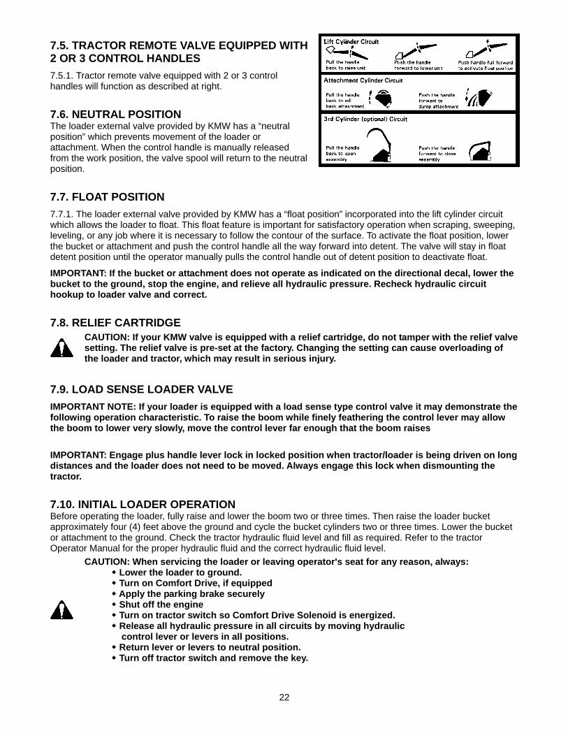
7.5. TRACTOR REMOTE VALVE EQUIPPED WITH 2 OR 3 CONTROL HANDLES 7.5.1. Tractor remote valve equipped with 2 or 3 control handles will function as described at right.
7.6. NEUTRAL POSITION The loader external valve provided by KMW has a “neutral position” which prevents movement of the loader or attachment. When the control handle is manually released from the work position, the valve spool will return to the neutral position.
7.7. FLOAT POSITION 7.7.1. The loader external valve provided by KMW has a “float position” incorporated into the lift cylinder circuit which allows the loader to float. This float feature is important for satisfactory operation when scraping, sweeping, leveling, or any job where it is necessary to follow the contour of the surface. To activate the float position, lower the bucket or attachment and push the control handle all the way forward into detent. The valve will stay in float detent position until the operator manually pulls the control handle out of detent position to deactivate float.
IMPORTANT: If the bucket or attachment does not operate as indicated on the directional decal, lower the bucket to the ground, stop the engine, and relieve all hydraulic pressure. Recheck hydraulic circuit hookup to loader valve and correct.
7.8. RELIEF CARTRIDGE
CAUTION: If your KMW valve is equipped with a relief cartridge, do not tamper with the relief valve setting. The relief valve is pre-set at the factory. Changing the setting can cause overloading of the loader and tractor, which may result in serious injury.
7.9. LOAD SENSE LOADER VALVE IMPORTANT NOTE: If your loader is equipped with a load sense type control valve it may demonstrate the following operation characteristic. To raise the boom while finely feathering the control lever may allow the boom to lower very slowly, move the control lever far enough that the boom raises
IMPORTANT: Engage plus handle lever lock in locked position when tractor/loader is being driven on long distances and the loader does not need to be moved. Always engage this lock when dismounting the tractor.
7.10. INITIAL LOADER OPERATION Before operating the loader, fully raise and lower the boom two or three times. Then raise the loader bucket approximately four (4) feet above the ground and cycle the bucket cylinders two or three times. Lower the bucket or attachment to the ground. Check the tractor hydraulic fluid level and fill as required. Refer to the tractor Operator Manual for the proper hydraulic fluid and the correct hydraulic fluid level.
CAUTION: When servicing the loader or leaving operator's seat for any reason, always: Lower the loader to ground. Turn on Comfort Drive, if equipped Apply the parking brake securely Shut off the engine Turn on tractor switch so Comfort Drive Solenoid is energized. Release all hydraulic pressure in all circuits by moving hydraulic control lever or levers in all positions. Return lever or levers to neutral position. Turn off tractor switch and remove the key.

23
IMPORTANT: Always keep the cylinders in a retracted position when the loader is not in use to guard against rust and contamination which may cause damage to the cylinder rods and hydraulic system.
7.11. REMOVING AIR FROM HYDRAULIC SYSTEM Repeat raising and lowering the loader boom and bucket operations until all the air is removed from the system and the system responds properly.
7.12. HOSE IDENTIFICATION Check if loader functions as shown and described on pages 21, 22 and 23. Then install colored nylon ties, one color per each circuit. Locate nylon ties so one is attached to male side of quick coupler and one is attached to female side of quick coupler. This will allow easy identification of loader circuits when mounting and dismounting loader.
7.13. EXTERNAL LOADER VALVE EQUIPPED WITH THIRD FUNCTION SOLENOID OPERATIONAL VALVE IMPORTANT NOTE: If your loader is equipped with a load sense type control valve it may demonstrate the following operation characteristic. To raise the boom while finely feathering the control lever may allow the boom to lower very slowly, move the control lever far enough that the boom raises.
7.13.1. Only activate one plus handle switch at a time.
7.13.2. 3rd spool valve should only be hooked to a loader 3rd function attachment such as a grapple fork. This valve spool is direct acting. The operator has no feathering control when operating this spool.
7.13.3. This valve is equipped with manual spool push points on each end of the 3rd function valve. The valve can be manually operated by pushing in on these push points. This feature will help you trouble shoot this section if it is necessary. Refer to Installation Instructions included with your Third Function External Valve Kit for detailed information. Refer to decal above.
7.13.4. When properly connected, the 3rd function valve should operate the grapple as follows. If not, switch 3rd function hoses around and try again. Refer to decals and illustration on this page.
(1) Press the number 1 left hand plus handle switch
to open the grapple. (2) Press the number 2 right hand plus handle switch
to close the grapple.
NOTE: If using the solenoid operated function for something other than KMW 4-Tine Grapple, orifice plate may need to be installed in your attachment to reduce speed of attachment and allow solenoid section of valve to function.
24
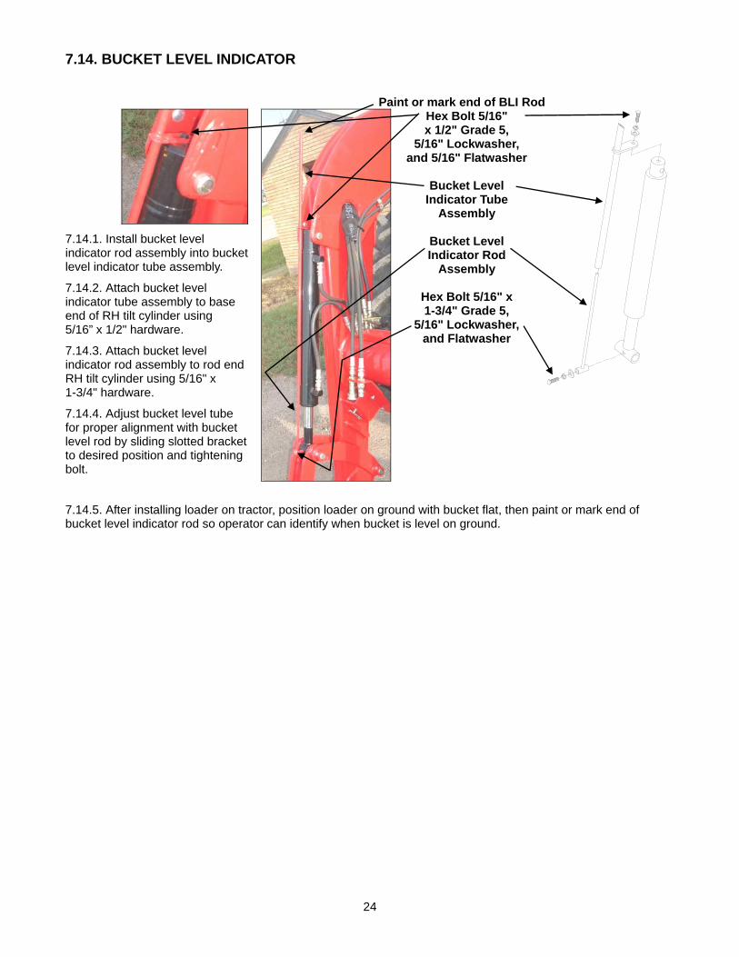
7.14. BUCKET LEVEL INDICATOR
Paint or mark end of BLI Rod
7.14.1. Install bucket level indicator rod assembly into bucket level indicator tube assembly.
7.14.2. Attach bucket level indicator tube assembly to base end of RH tilt cylinder using 5/16” x 1/2" hardware.
7.14.3. Attach bucket level indicator rod assembly to rod end RH tilt cylinder using 5/16" x 1-3/4" hardware.
7.14.4. Adjust bucket level tube for proper alignment with bucket level rod by sliding slotted bracket to desired position and tightening bolt.
Hex Bolt 5/16" x 1/2" Grade 5,
5/16" Lockwasher, and 5/16" Flatwasher
Bucket Level
Indicator Tube Assembly
Bucket Level Indicator Rod
Assembly
Hex Bolt 5/16" x 1-3/4" Grade 5,
5/16" Lockwasher, and Flatwasher
7.14.5. After installing loader on tractor, position loader on ground with bucket flat, then paint or mark end of bucket level indicator rod so operator can identify when bucket is level on ground.

25
8. DAILY MAINTENANCE & LUBRICATION 8.1. DAILY CHECKS 8.1.1. All Loader Models: Check all hardware daily before operation. Tighten hardware to torque values as specified in the Torque Chart, page 107 unless otherwise specified.
IMPORTANT NOTE: To prevent mounting kit hardware from loosening during operation always torque mounting kit hardware to specified torque noted in Loader Operator Manual.
8.1.2. All Loader Models: With the engine off and the bucket on the ground, inspect all hoses for cuts or wear. Check for signs of leaks and make sure all fittings are tight.
CAUTION: Escaping hydraulic fluid under pressure can have sufficient force to penetrate skin, causing serious personal injury. Before disconnecting lines, be sure to relieve all pressure. Before applying pressure to system, be sure all connections are tight and that lines, tubes, and hoses are not damaged. Fluid escaping from a very small hole can be almost invisible. Use a piece of cardboard or wood, rather than hands, to search for suspected leaks. If injured by escaping fluid, see a doctor at once. Serious infection or reaction can develop if proper medical treatment is not administered immediately.
(1) Hydraulic line. (2) Cardboard. (3) Magnifying glass.
Service your loader at the intervals and locations as specified. When you service your loader, use only high quality lubricants. The engine hour meter on the tractor shows the amount of hours the engine has worked. Use the hour meter to service your loader at the correct time periods.
CAUTION: When servicing the loader or leaving operator's seat for any reason, always: Lower the loader to ground. Turn on Comfort Drive, if equipped Apply the parking brake securely Shut off the engine Turn on tractor switch so Comfort Drive Solenoid is energized. Release all hydraulic pressure in all circuits by moving hydraulic control lever or levers in all positions. Return lever or levers to neutral position. Turn off tractor switch and remove the key.
Check the tractor hydraulic fluid level as specified in the tractor Operator Manual.
NOTE: When checking hydraulic system fluid level, the loader boom must be on the ground with the bucket or attachment resting flat on a level surface.

26
8.2. LOADER LUBRICATION 8.2.1. Model 1860 Loader: Position bucket and/or attachment level with ground, lower loader boom to ground, and relieve all hydraulic pressure before lubricating.
8.2.2. Model 1860 Loader: There are 20 grease fittings on this loader. Lubricate pivots as specified.
(1) Lubricate these 14 pivot points every 5 hours of operation.
(2) Lubricate these 6 grease fittings, 3 on each
pivot every 5 hours of operation.
CAUTION: Do not stand, walk, or work under a raised loader or attachment unless it is securely blocked or held in position. Accidental movement of a control lever/levers or leaks in the hydraulic system could cause the loader to drop, or attachment to dump, causing severe injury.
8.2.3. All Model Loaders: After every 10 hours of loader operation, check that all pin boss hardware, washers, and nuts are secure.
Hex Bolt 7/16”-14 x 2.5" Grade 8, 4 places.
Flatwasher 3/8" Hardened, 4 places.
Stover Lock Nut 7/16”-14, 4 places.
Stover Lock Nut 3/8"-16NC, 4 places.
Carriage Bolt 3/8"-16NC x 1-1/2" Grade 5, 4 places.
Position 1 Hardware Position 2 Hardware
1
1
1
1
2
1
1
2
2
2

27
8.2.4. All Model Loaders: To keep mounting kit hardware from loosening during operation, periodically check that all loader mounting kit hardware is torqued to specification noted in Torque Chart, page 107.
(1) NOTE: Check all mounting kit hardware torque after initial loader operation and then after every 25 hours of loader operation. (Refer to mounting kit instructions for exact quantity and placement of hardware)
8.2.5. All Loader Models: During initial setup and as required apply a small amount of grease to each loader bracket in area of top receiver and guide. This will aid in parking loader.
(2) To aid in mounting and dismounting loader, apply small amount of grease to these areas.
2
8.2.6. All Model Loaders: Before servicing your tractor, always do one of the following.
CAUTION: Do not stand, walk, or work under a raised loader or attachment unless it is securely blocked or held in position. Accidental movement of a control lever/levers or leaks in the hydraulic system could cause the loader to drop, or attachment to dump, causing severe injury.
(1) Park the loader off of the tractor. (2) Position loader bucket against dump stops,
then lower to ground and relieve all hydraulic pressure.
2
2
2

28
8.2.7. All Model Loaders: To prevent attachment cylinder damage, always keep top of front loader arms and area between attaching plates free of all debris such as rocks or material that can become hard when dried or frozen.
(1) Keep This Area Clean— Top of front loader arms.
(2) Keep This Area Clean— Between attaching plates.
8.2.8. Check mounting kit hardware as specified below. IMPORTANT: To keep mounting kit hardware from loosening during loader operation, hardware must be torqued to specifications noted in operator manual.
(1) Keep Clean
(2) Keep Clean
29
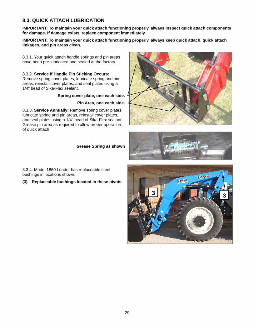
8.3. QUICK ATTACH LUBRICATION IMPORTANT: To maintain your quick attach functioning properly, always inspect quick attach components for damage. If damage exists, replace component immediately.
IMPORTANT: To maintain your quick attach functioning properly, always keep quick attach, quick attach linkages, and pin areas clean.
8.3.1. Your quick attach handle springs and pin areas have been pre-lubricated and sealed at the factory.
8.3.2. Service If Handle Pin Sticking Occurs: Remove spring cover plates, lubricate spring and pin areas, reinstall cover plates, and seal plates using a 1/4" bead of Sika-Flex sealant.
Spring cover plate, one each side.
Pin Area, one each side.
8.3.3. Service Annually: Remove spring cover plates, lubricate spring and pin areas, reinstall cover plates, and seal plates using a 1/4" bead of Sika-Flex sealant. Grease pin area as required to allow proper operation of quick attach
Grease Spring as shown
8.3.4. Model 1860 Loader has replaceable steel bushings in locations shown.
(3) Replaceable bushings located in these pivots.
33
30
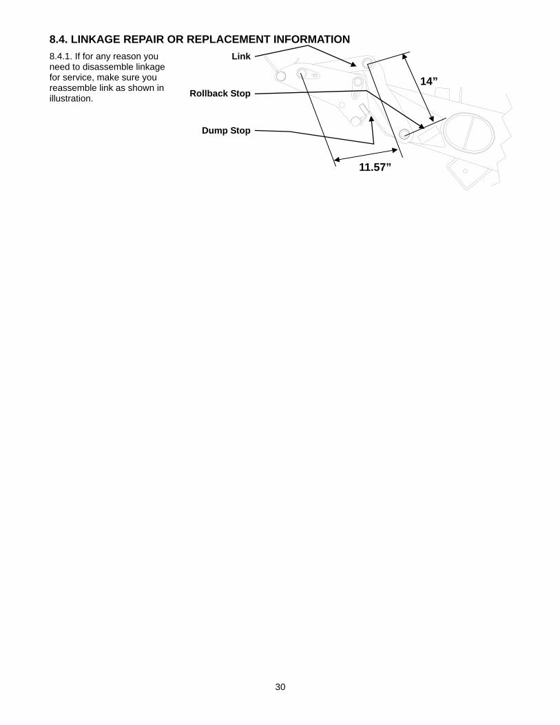
8.4. LINKAGE REPAIR OR REPLACEMENT INFORMATION 8.4.1. If for any reason you need to disassemble linkage for service, make sure you reassemble link as shown in illustration.
Link
Rollback Stop
Dump Stop
14”
11.57”

31
9. OPERATING INSTRUCTIONS The loader should be operated with the tractor engine running from 1700 to 2200 rpm. Excessive speeds are dangerous, and may cause bucket spillage and unnecessary strain on the tractor and loader. When operating in temperatures below 30oF, run the tractor engine below 1200 rpm until the hydraulic fluid temperature exceeds 30oF. The following text and illustrations offer suggested loader and tractor operating techniques. IMPORTANT: If your loader is equipped with Optional Hydraulic Self Leveling refer to following operating instructions along with operating instructions in Optional Hydraulic Self Leveling section in this manual.
9.1. FILLING THE BUCKET Approach and enter the pile with a level bucket. Then rollback and lift the bucket.
The rollback and lifting of the bucket will increase efficiency because a level bucket throughout the lifting cycle resists bucket lift and increases breakaway effort.
NOTE: Do not be concerned if the bucket is not completely filled during each pass. Maximum productivity is determined by the amount of material loaded in a given period of time. Time is lost if two or more attempts are made to fill the bucket on each pass.
LIFTING THE LOAD When lifting the load, keep the bucket positioned to avoid spillage.
CAUTION: Do not attempt to lift bucket or attachment loads in excess of the loader capacity.
9.2. CARRYING THE LOAD Position the loader in a low position when transporting a loaded or empty bucket or attachment. Use extreme care when operating the loader on a slope. Keep the bucket as low as possible. This keeps the bucket and tractor center of gravity low and will provide maximum tractor stability.
CAUTION: Operating the loader on a hillside is dangerous and is not recommended.
When transporting a load, keep the bucket as low as possible to avoid tipping, in case a wheel drops in a rut.

32
9.3. DUMPING THE BUCKET Lift the bucket just high enough to clear the side of the vehicle. Move the tractor in as close to the side of the vehicle as possible, then dump the bucket.
9.4. LOWERING THE BUCKET After the bucket is dumped, back away from the vehicle while lowering and rolling back the bucket.
9.5. OPERATING WITH FLOAT CONTROL During operation on hard surface, keep the bucket level and position the lift control in the float position to permit the bucket to float on the work surface.�If hydraulic down pressure is exerted on the bucket, the cutting edge will wear faster than normal.
The float position will also avoid mixing of surface material with stockpile material. The float position will reduce the chance of surface gouging while removing snow or other material, or when working with a blade. NOTE: Float will not function on loaders installed on Open-Center hydraulic system with Hydraulic Self-Leveling option installed.
9.6. LOADING FROM A BANK Choose a forward gear that provides a safe ground speed and power for loading.
CAUTION: Exercise caution when undercutting high banks. Dirt slides can be dangerous. Load from as low as possible for maximum efficiency. Loader lift and breakaway capacity diminish as loading height is increased.
Side cutting is a good technique for cutting down a big pile.
If the pile sides are too high and liable to cause cave-in, use the loader to break down the sides until a slot can be cut over the top.
Another method for large dirt piles is to build a ramp approach to the pile.
It is important to keep the bucket level when approaching a bank or pile. This will help avoid gouging the work area.

33
9.7. PEELING AND SCRAPING Use a slight bucket down angle, travel forward, and hold the lift control forward to start the cut. Make a short cut and breakout cleanly.
With the bucket level, start a cut at the notch approximately 2 in. deep. Hold the depth by feathering the tilt control to adjust the cutting edge up or down. When the front tires enter the notch, adjust the lift cylinder to maintain proper depth.
Make additional passes until the desired depth is reached. During each pass, use only the tilt control while at working depth. This will allow you to concentrate on controlling the bucket angle to maintain a precise cut.
NOTE: See page 36 and 37 for information on how loader will operate if circuit reliefs activate during operation.
9.8. LOADING LOW TRUCKS OR SPREADERS FROM A PILE For faster loading, minimize the angle of turn and length of run between pile and spreader.
Back grade occasionally with a loaded bucket to keep the work surface free of ruts and holes. Also, hold the lift control forward so the full weight of the bucket is scraping the ground. Use the heel of the bucket.
9.9. BACKFILLING Approach the pile with the bucket flat.
Poor operating methods actually move no more dirt and make it more difficult to hold a level grade. Do not use the bucket in the dumped position for bulldozing. This method will impose severe shock loading on the dump-linkage, the tilt cylinders, and the tractor.
Leave dirt in the bucket because dumping on each pass wastes time.
Operate at right angles to the ditch, taking as big a bite as the tractor can handle.
34
Leave dirt that drifts over the side of the bucket for final clean up.
Pile dirt on the high side for easier backfilling on a slope.
9.10. HANDLING LARGE HEAVY OBJECTS
CAUTION: Handling large heavy objects can be extremely dangerous due to: • Danger of rolling the tractor over. • Danger of upending the tractor. • Danger of object rolling or sliding down the loader boom onto the operator.
CAUTION: If you must perform the above work, protect yourself by: • Never lifting the load higher than necessary to clear the ground when moving. • Adding rear ballast to the tractor to compensate for the load. • Never lifting large objects with equipment that does not have an anti-rollback device. • Moving slowly and carefully; avoiding rough terrain.
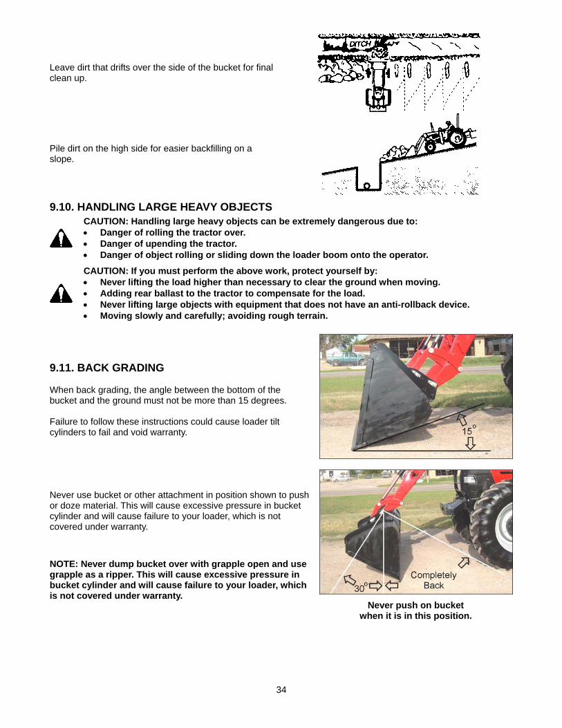
9.11. BACK GRADING When back grading, the angle between the bottom of the bucket and the ground must not be more than 15 degrees. Failure to follow these instructions could cause loader tilt cylinders to fail and void warranty.
Never use bucket or other attachment in position shown to push or doze material. This will cause excessive pressure in bucket cylinder and will cause failure to your loader, which is not covered under warranty.
NOTE: Never dump bucket over with grapple open and use grapple as a ripper. This will cause excessive pressure in bucket cylinder and will cause failure to your loader, which is not covered under warranty.
Never push on bucket when it is in this position.

35
9.12. PROHIBITED OPERATIONS
9.12.1. Never perform following operation with a loader. Failure to follow these instructions could cause high pressure spikes in system causing failure or damage to cylinders, hoses or loader frame members. Step 1: Extend lift cylinder Step 2: Hook bucket edge to solid object Step 3: Apply force with bucket cylinders
CAUTION: Doing this type of operation with your tractor and loader could result in personal injury or death.
9.12.2. Never perform following operation with a loader. Failure to follow these instructions could cause high pressure spikes in system causing failure or damage to cylinders, hoses or loader frame members. Step 1: Extend lift cylinder Step 2: Connect chain or nylon strap to bucket
and solid object Step 3: Apply force with bucket cylinders Step 4: Drive tractor forward or rearward
CAUTION: Doing these types of loader operations with your tractor and loader could result in personal injury or death. Damage caused to any of these components due to these types of loader operations are not covered under warranty.
Step 2: Hook bucket edge to solid object
Step 1: Extend lift cylinders
Step 3: Apply force with bucket cylinders
Step 3: Apply force with bucket cylinders
Step 1: Extend lift cylinders
Step 2: Connect chain or nylon strap to bucket and solid object
Step 4: Drive tractor forward or rearward
36
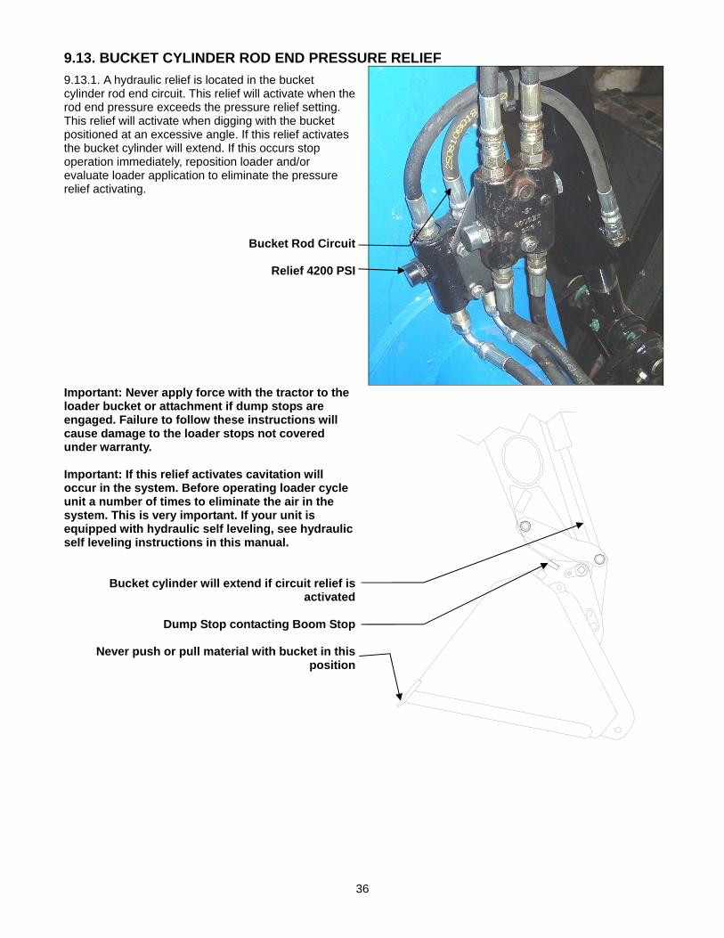
9.13. BUCKET CYLINDER ROD END PRESSURE RELIEF 9.13.1. A hydraulic relief is located in the bucket cylinder rod end circuit. This relief will activate when the rod end pressure exceeds the pressure relief setting. This relief will activate when digging with the bucket positioned at an excessive angle. If this relief activates the bucket cylinder will extend. If this occurs stop operation immediately, reposition loader and/or evaluate loader application to eliminate the pressure relief activating.
Bucket Rod Circuit
Relief 4200 PSI
Important: Never apply force with the tractor to the loader bucket or attachment if dump stops are engaged. Failure to follow these instructions will cause damage to the loader stops not covered under warranty. Important: If this relief activates cavitation will occur in the system. Before operating loader cycle unit a number of times to eliminate the air in the system. This is very important. If your unit is equipped with hydraulic self leveling, see hydraulic self leveling instructions in this manual.
Bucket cylinder will extend if circuit relief is activated
Dump Stop contacting Boom Stop
Never push or pull material with bucket in this position

37
9.14. LIFT CYLINDER ROD END PRESSURE RELIEF 9.14.1. A hydraulic relief is located in the lift cylinder rod end circuit. This relief will activate when the rod end pressure exceeds this pressure relief setting. This relief could activate while back dragging with the loader or when putting downward force on the cutting edge with the lift cylinder circuit in the neutral position. If this relief activates the lift cylinders will extend.
Lift Rod Circuit
Relief 5200 PSI
DANGER: Never use the loader to lift front end of tractor off of the ground to service the unit. Failure to follow these instructions could cause personal injury or death.
Important: If this relief activates cavitation will occur in the system. Before operating loader cycle unit a number of times to eliminate the air in the system. This is very important. If your unit is equipped with hydraulic self leveling, see hydraulic self leveling instructions in this manual.

38
10. DISMOUNTING THE LOADER
CAUTION: Always park loader with material bucket attached to the loader.
CAUTION: When servicing the loader or leaving operator's seat for any reason, always: Lower the loader to ground. Turn on Comfort Drive, if equipped Apply the parking brake securely Shut off the engine Turn on tractor switch so Comfort Drive Solenoid is energized. Release all hydraulic pressure in all circuits by moving hydraulic control lever or levers in all positions. Return lever or levers to neutral position. Turn off tractor switch and remove the key.
CAUTION: Do not stand, walk, or work under a raised loader or attachment unless it is securely blocked or held in position. Accidental movement of valve handle/handles or leaks in the hydraulic system could cause the loader to drop, or attachment to dump, causing severe injury.
CAUTION: Do not allow bystanders in loader work area.
IMPORTANT: Never allow weight of tractor to be placed on parking stands when mounting or dismounting loader.
10.1.1. Position the loader on a hard level surface. The more level the surface the easier the loader is to mount and dismount.
10.1.2. Raise loader, dump bucket 90o to ground, and then lower loader so that bucket cutting edge is approximately 1/2" off of ground.
Bearing Box
Tower
Cutting edge of bucket1/2" off of ground.
10.1.3. Remove snap pins from handle pins located in bearing boxes.
Bearing Box
Handle Pin
Snap Pin

39
10.1.4. Remove parking stands from storage positions in the boom crosstubes. Return hairpin cotters to storage positions.
Hairpin Cotterin Storage Position.
Parking Standin Storage Position.
10.1.5. Position parking stands in attaching brackets as shown. Secure using clevis pins and hairpin cotters.
Clevis Pin and Hairpin Cotter
in Park Position.
Attaching Bracket.
Parking Standin Park Position.

40
10.1.6. Make sure long end of parking stand is located toward rear end of tractor. Photo shows parking stands in park position and loader ready to be dismounted.
Parking Stands in Park Position
with long end of standspositioned rearward.
10.1.7. If your loader is equipped with Comfort Drive, Lower the loader to ground. Turn on Comfort Drive, if equipped Apply the parking brake securely Shut off the engine Turn on tractor switch so Comfort Drive Solenoid is energized. Release all hydraulic pressure in all circuits by moving hydraulic control lever or levers in all positions. Return lever or levers to neutral position. Turn off tractor switch and remove the key. then disconnect Comfort Drive electrical disconnect located on RH side of tractor in area of Mid Mount Coupler Kit or Mid Mount Faster Coupler Kit.
10.1.8. Retract tilt cylinders (A) to roll bucket back and retract lift cylinders (B) to lower loader boom down until parking stands make firm contact with ground.
NOTE: Driving the tractor forward slowly while positioning loader will allow parking stands to contact ground firmly.
Bucket resting on ground.
Parking Standscontacting ground firmly.
AB

41
10.1.9. Retract lift cylinders (C) until bearing box pins (D) rotates out of bracket towers.
10.1.10. Slowly drive tractor forward while (E) retracting tilt cylinders (F). Doing this will allow bearing boxes to guide loader as it is being parked off of tractor. This will allow loader to be held in position to clear exhaust and tractor hood during dismounting.
Bearing Boxes
10.1.11. Retract tilt cylinders (G) completely.
10.1.12. Make sure all loader components clear tractor. Back tractor away (H) slightly.
10.1.13. Stop the tractor engine and then work valve handle/handles to relieve hydraulic fluid pressure in lines. Refer to tractor operator manual for additional information.
C D
FE
GH

42
10.1.14. Reinstall handle pins and snap pins to bearing boxes for storage.
10.1.15. Disconnect loader hoses. Start tractor and slowly back tractor away from the loader.
Store Handle Pins and Snap Pins in Bearing Box
IMPORTANT: To avoid hydraulic hose damage, be alert and make sure hoses do not catch on tractor and/or loader during mounting or dismounting.
WARNING: Make sure parked loader is on a hard level surface. Engage all safety devices to prevent loader from falling and being damaged or injuring someone. Do not repair loader if it is not mounted on the tractor. Loss of hydraulic fluid or removal of parts could cause loader to collapse resulting in injury.

43
11. MOUNTING THE LOADER
CAUTION: Do not stand, walk, or work under a raised loader or attachment unless it is securely blocked or held in position. Accidental movement of valve handle/handles or leaks in the hydraulic system could cause the loader to drop, or attachment to dump, causing severe injury.
CAUTION: Do not allow bystanders in loader work area.
IMPORTANT: Never allow weight of tractor to be placed on parking stands when mounting or dismounting loader.
11.1.1. To aid in mounting and dismounting loader, apply a small amount of grease, if needed, to each tower in areas of tower bottom receiver (A), tower top receiver (B), handle pin bushing (C) and tower guides (D).
Tower
11.1.2. Slowly drive tractor forward to a position where the loader hoses can be connected to the tractor.
11.1.3. Stop the engine. Connect the loader hydraulic hoses.
11.1.4. Remove handle pins and snap pins from bearing boxes.
B
AC
D

44
11.1.5. Check that lift cylinders are fully retracted. Position loader to clear tractor muffler and hood. Then drive tractor forward. Use tilt cylinders to position height of bearing box top pin making sure all loader components clear all tractor components.
Bearing Box Top Pin
Tower Top Receiver
Bearing Box
Tower
11.1.6. Align bearing box top pin with tower top receiver guide post, both sides. Make sure loader is centered right to left on both towers. Extend tilt cylinders further until top bearing box pin seats in both towers.
Tower
Bearing Box Bottom Pin
Bearing Box CenteredRight to Left on Tower
Bearing Box Top Pin
Tower Top Receiver Guide Post
Tower Top Receiver
Bearing Box
11.1.7. Extend lift cylinders (A) slowly making sure loader seats completely in tower top receivers (B) and tower bottom receivers (C).
DA
B
C

45
11.1.8. Extend tilt cylinders (D) until bucket is approximately 1/2" off ground.
11.1.9. Secure loader to mounting brackets as follows.
11.1.10. While raising loader slightly, position bucket 90o to ground then lower until cutting edge is 1/2" off of ground.
11.1.11. Reinstall handle pins to bearing boxes and secure using snap pins.
Bearing Box
Handle Pin
Snap Pin
11.1.12. Remove parking stands from parked position. Return clevis pins and hairpin cotters to attaching brackets for storage.
Clevis Pin and Hairpin Cotterin Park Position.
Attaching Bracket.
Parking Standin Park Position.
D
46
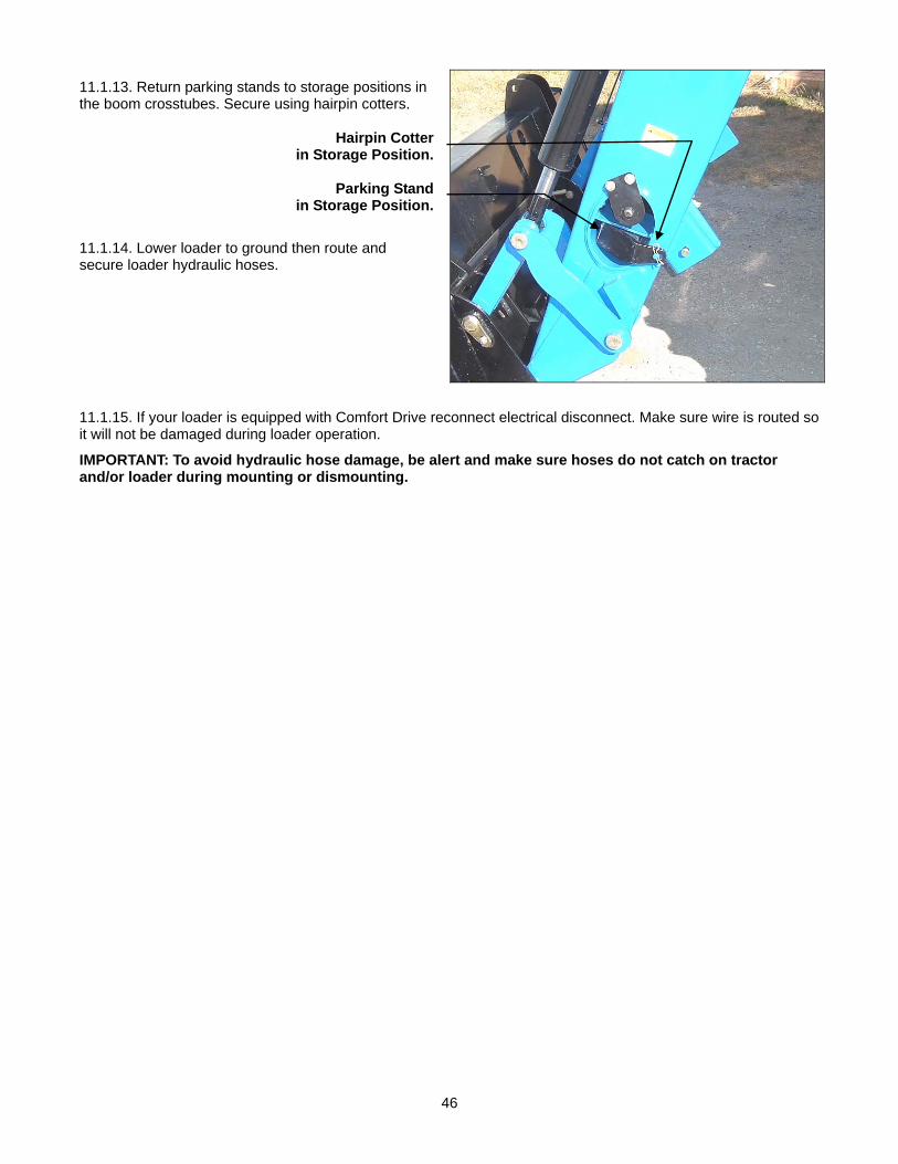
11.1.13. Return parking stands to storage positions in the boom crosstubes. Secure using hairpin cotters.
Hairpin Cotterin Storage Position.
Parking Standin Storage Position.
11.1.14. Lower loader to ground then route and secure loader hydraulic hoses.
11.1.15. If your loader is equipped with Comfort Drive reconnect electrical disconnect. Make sure wire is routed so it will not be damaged during loader operation.
IMPORTANT: To avoid hydraulic hose damage, be alert and make sure hoses do not catch on tractor and/or loader during mounting or dismounting.

47
12. QUICK ATTACH – INSTALLATION AND OPERATION IMPORTANT: Read safety information in this section and on decal before operating quick attach.
Model 1860 Loader: Quick Attach is standard equipment.
WARNING: Always read and follow operating instructions before operating quick attach.
12.1. INSTALLATION INSTRUCTIONS IMPORTANT: Do not extend tilt cylinders without quick attach installed on loader. Failure to follow these instructions could cause damage to loader, which is not covered under warranty.
12.2. OPERATING INSTRUCTIONS
CAUTION: Except when detaching or attaching a quick attach bucket or attachment to your quick attach, always position the quick attach handle in the handle engaged position, Figure 3, page 49. This will prevent accidental tripping of quick attach handle when not in use.
CAUTION: To avoid personal injury, keep hands and feet away from loader when operating.
IMPORTANT: To maintain your quick attach functioning properly, always inspect quick attach components for damage. If damage exists, replace component immediately.
IMPORTANT: To maintain your quick attach functioning properly, always keep quick attach, quick attach linkages, and pin areas clean.
Quick Attach Handle Linkages
Quick Attach Pin Area
Quick Attach Handle
Quick Attach Notch
Quick Attach Attachment

48
12.3. NON-FACTORY APPROVED ATTACHMENTS IMPORTANT: It is strongly recommended that only KMW Factory Approved Attachments specified in KMW Sales Manual be used with KMW Loaders. However, if you are going to use another brand of attachment on this loader check the following before proceeding.
12.3.1. Check that dimensions of attachment matches drawing below. If your attachment does not match these dimensions, do not use attachment on your KMW Loader.
12.3.2. Check attachment operation when installing for first time, A. Make sure quick attach engages attachment and locking pins works correctly. B. Slowly roll attachment completely back and then function grapple or attachment through its open and
closed function making sure it clears all loader components. C. Slowly dump attachment against stops. D. Then function grapple or attachment through its open and closed function making sure it clears all
loader components.
IMPORTANT: Failure to follow above instructions could cause damage to loader components from contact with attachment which are not covered under warranty.
Accept 1-9/16” to 1-5/8” diameter rod
.86” diameter
31.102” 42.929”
1.5”
1”
25 degrees
12.6247”
9.4527” min.
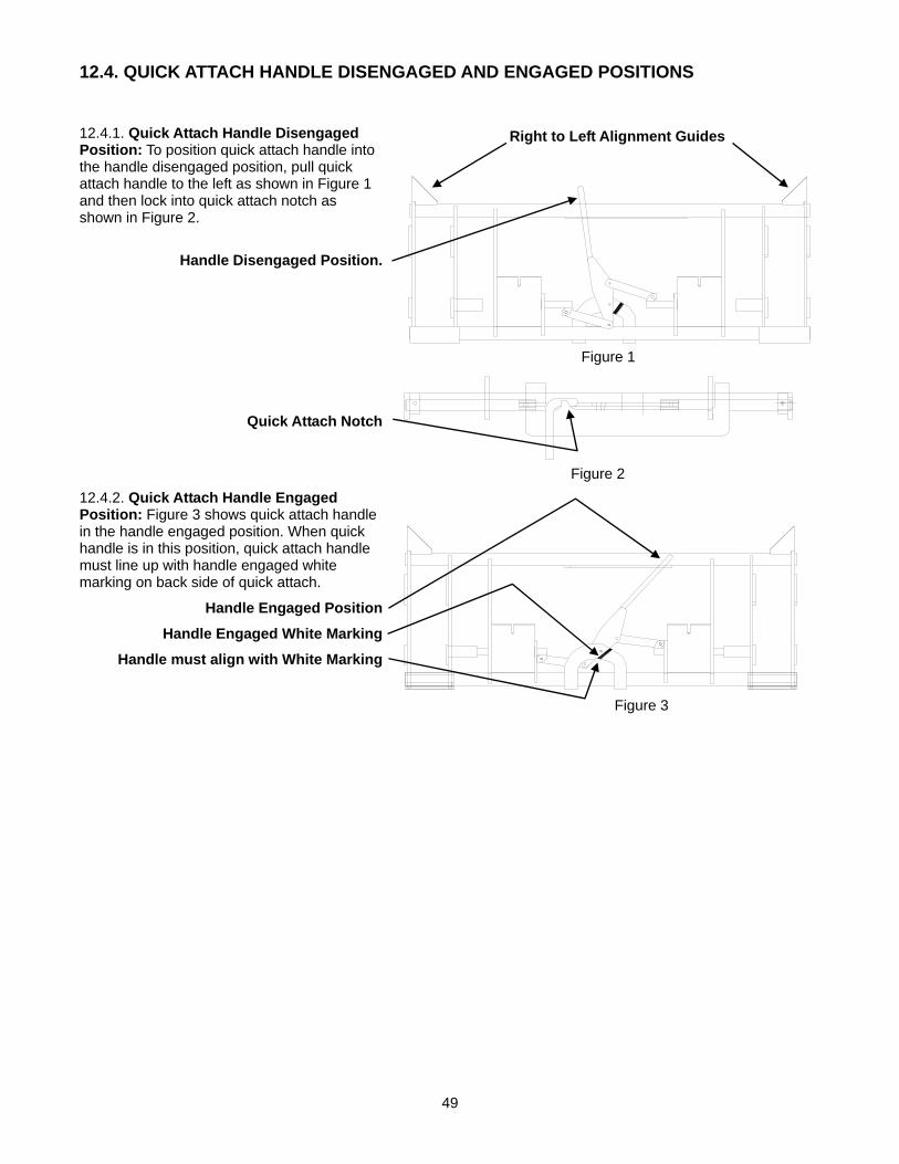
49
12.4. QUICK ATTACH HANDLE DISENGAGED AND ENGAGED POSITIONS
12.4.1. Quick Attach Handle Disengaged Position: To position quick attach handle into the handle disengaged position, pull quick attach handle to the left as shown in Figure 1 and then lock into quick attach notch as shown in Figure 2.
Handle Disengaged Position.
Quick Attach Notch
12.4.2. Quick Attach Handle Engaged Position: Figure 3 shows quick attach handle in the handle engaged position. When quick handle is in this position, quick attach handle must line up with handle engaged white marking on back side of quick attach.
Handle Engaged Position
Handle Engaged White Marking
Handle must align with White Marking
Figure 2
Figure 3
Figure 1
Right to Left Alignment Guides
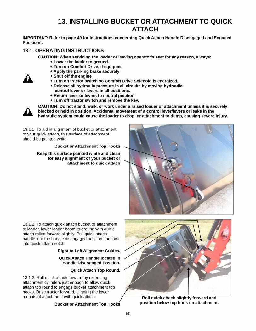
50
13. INSTALLING BUCKET OR ATTACHMENT TO QUICK ATTACH
IMPORTANT: Refer to page 49 for Instructions concerning Quick Attach Handle Disengaged and Engaged Positions.
13.1. OPERATING INSTRUCTIONS
CAUTION: When servicing the loader or leaving operator's seat for any reason, always: Lower the loader to ground. Turn on Comfort Drive, if equipped Apply the parking brake securely Shut off the engine Turn on tractor switch so Comfort Drive Solenoid is energized. Release all hydraulic pressure in all circuits by moving hydraulic control lever or levers in all positions. Return lever or levers to neutral position. Turn off tractor switch and remove the key.
CAUTION: Do not stand, walk, or work under a raised loader or attachment unless it is securely blocked or held in position. Accidental movement of a control lever/levers or leaks in the hydraulic system could cause the loader to drop, or attachment to dump, causing severe injury.
13.1.1. To aid in alignment of bucket or attachment to your quick attach, this surface of attachment should be painted white.
Bucket or Attachment Top Hooks
Keep this surface painted white and cleanfor easy alignment of your bucket or
attachment to quick attach
13.1.2. To attach quick attach bucket or attachment to loader, lower loader boom to ground with quick attach rolled forward slightly. Pull quick attach handle into the handle disengaged position and lock into quick attach notch.
Right to Left Alignment Guides.
Quick Attach Handle located in Handle Disengaged Position.
Quick Attach Top Round.
13.1.3. Roll quick attach forward by extending attachment cylinders just enough to allow quick attach top round to engage bucket attachment top hooks. Drive tractor forward, aligning the lower mounts of attachment with quick attach.
Bucket or Attachment Top Hooks
Roll quick attach slightly forward and
position below top hook on attachment.
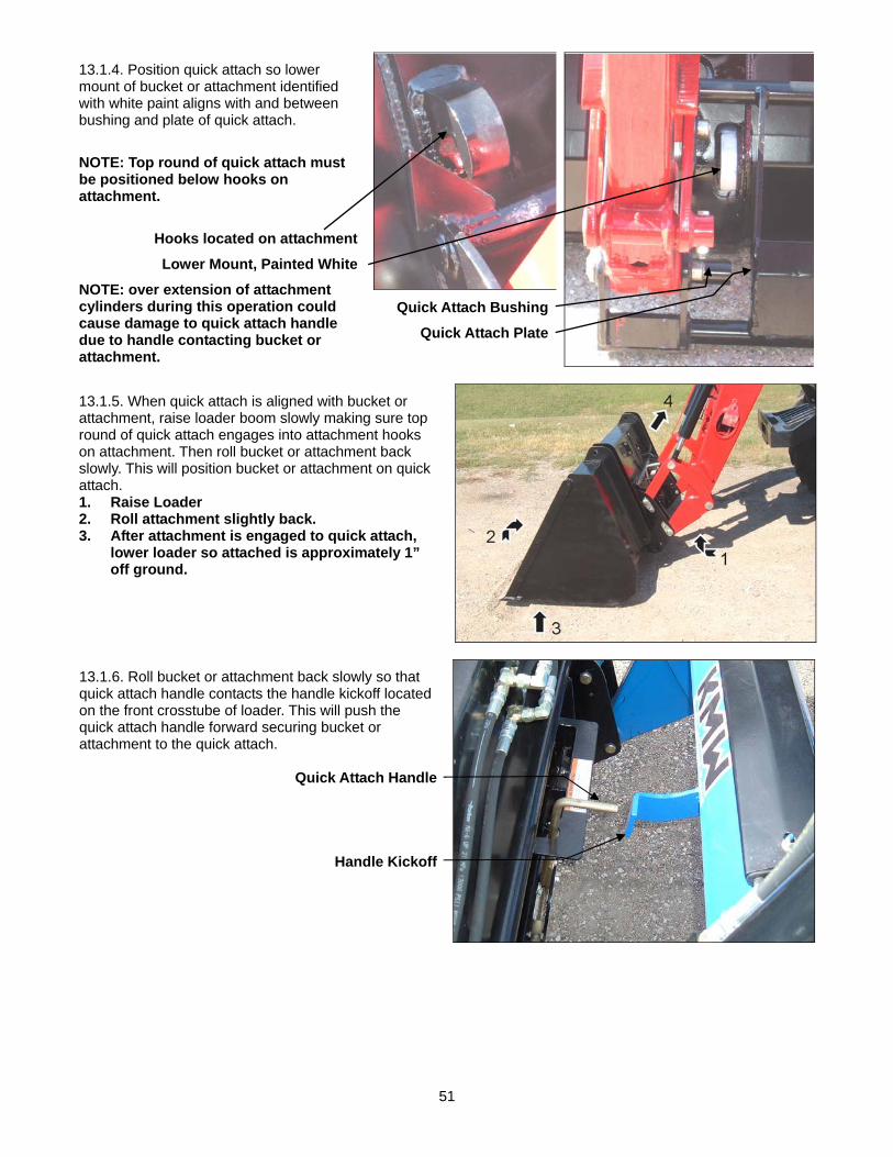
51
13.1.4. Position quick attach so lower mount of bucket or attachment identified with white paint aligns with and between bushing and plate of quick attach.
NOTE: Top round of quick attach must be positioned below hooks on attachment.
Hooks located on attachment
Lower Mount, Painted White
NOTE: over extension of attachment cylinders during this operation could cause damage to quick attach handle due to handle contacting bucket or attachment.
Quick Attach Bushing
Quick Attach Plate
13.1.5. When quick attach is aligned with bucket or attachment, raise loader boom slowly making sure top round of quick attach engages into attachment hooks on attachment. Then roll bucket or attachment back slowly. This will position bucket or attachment on quick attach. 1. Raise Loader 2. Roll attachment slightly back. 3. After attachment is engaged to quick attach,
lower loader so attached is approximately 1” off ground.
13.1.6. Roll bucket or attachment back slowly so that quick attach handle contacts the handle kickoff located on the front crosstube of loader. This will push the quick attach handle forward securing bucket or attachment to the quick attach.
Quick Attach Handle
Handle Kickoff

52
13.1.7. Check to see that quick attach has been latched to attachment by rolling quick attach bucket or attachment back and then raising loader boom to hood height.
NOTE: Quick attach handle must be located in the handle engaged position. Refer to photo at right and Figure 3 page 49.
Quick Attach Handle should align with White Mark on Quick Attach as shown.
13.1.8. Check that quick attach bucket or attachment is securely attached to quick attach by raising loader boom 3 to 4 feet, dumping bucket or attachment 20 to 30 degrees to ground, lowering loader to ground and putting downward pressure on bucket or attachment. Check to be sure bucket or attachment does not roll out of quick attach.
Roll attachment forward. Attachment should
not rollout of quick attach.
CAUTION: Do not allow bystanders in loader work area.
WARNING: A bucket or attachment that is not securely locked into quick attach could come off during loader operation causing serious injury or death.
13.1.9. Inspect quick attaching areas to verify that quick attach pins have engaged bucket or attachment engaging bar fully. This can be done with attachment rolled forward slightly or flat on ground.
Quick Attach Pin
Quick Attach Plate
Bucket or Attachment Engaging Bar
Quick Attach Pin Bushing
13.1.10. If installing an attachment utilizing a third cylinder hydraulic circuit, connect hoses to quick couplers.

53
14. REMOVING BUCKET OR ATTACHMENT FROM QUICK ATTACH
IMPORTANT: Refer to page 49 for instructions concerning Quick Attach Handle Disengaged and Engaged Positions.
CAUTION: When servicing the loader or leaving operator's seat for any reason, always: Lower the loader to ground. Turn on Comfort Drive, if equipped Apply the parking brake securely Shut off the engine Turn on tractor switch so Comfort Drive Solenoid is energized. Release all hydraulic pressure in all circuits by moving hydraulic control lever or levers in all positions. Return lever or levers to neutral position. Turn off tractor switch and remove the key.
CAUTION: Do not stand, walk, or work under a raised loader or attachment unless it is securely blocked or held in position. Accidental movement of a control lever/levers or leaks in the hydraulic system could cause the loader to drop, or attachment to dump causing severe injury.
14.1. OPERATING INSTRUCTIONS 14.1.1. To disconnect bucket or attachment from loader, position bucket or attachment slightly rolled back and approximately 1” off of ground. Refer to photo at right. Then pull quick attach handle into the handle disengaged position and lock into quick attach notch. Refer to Figure 1 and 2, page 49.
Quick Attach Handle
CAUTION: Never leave loader valve in float position while doing this procedure. Loader could drop suddenly causing severe injury.
14.1.2. Roll bucket or attachment forward and lower to ground. Back tractor/loader away from bucket or attachment. Refer to photo at right. Then roll quick attach back. Return quick attach handle to latch position. Refer to Figure 3, page 49.
NOTE: Over extension of attachment cylinders during this operation could cause damage to quick attach handle due to handle contacting bucket or attachment
14.1.3. If removing an attachment utilizing a third cylinder hydraulic circuit, disconnect hoses from quick couplers. Connect attachment male and female quick couplers together to reduce chance of pressure intensification while attachment is parked.
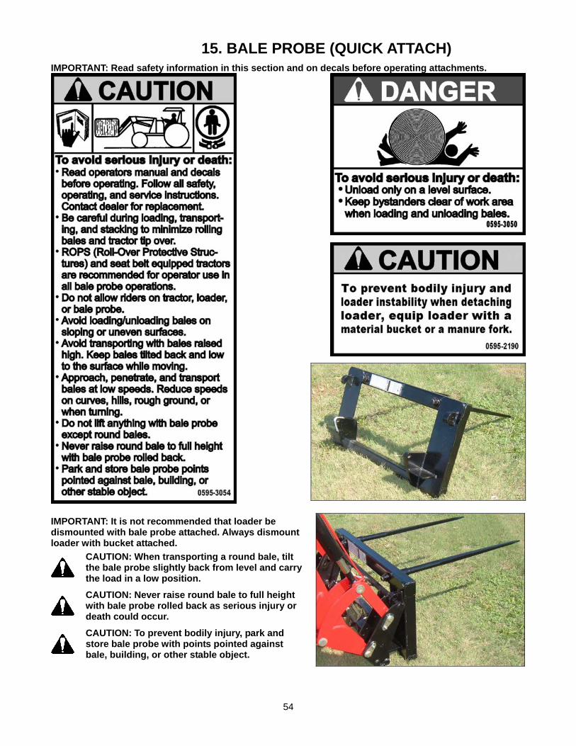
54
15. BALE PROBE (QUICK ATTACH) IMPORTANT: Read safety information in this section and on decals before operating attachments.
IMPORTANT: It is not recommended that loader be dismounted with bale probe attached. Always dismount loader with bucket attached.
CAUTION: When transporting a round bale, tilt the bale probe slightly back from level and carry the load in a low position.
CAUTION: Never raise round bale to full height with bale probe rolled back as serious injury or death could occur.
CAUTION: To prevent bodily injury, park and store bale probe with points pointed against bale, building, or other stable object.

55
15.1. BALE PROBE ATTACHMENT IMPORTANT: The bale probes are a high strength alloy – drop forged steel and should not be welded or heat-treated.
IMPORTANT: Maximum load limit on bale probe attachment is 2,000 pounds.
15.2. ASSEMBLY INSTRUCTIONS 15.2.1. Install each Bale Probe into a tapered sleeve and secure with nut. Torque nut to 515 ft. lb. Failure to follow these instructions could cause damage to probe and void your warranty. (1) Probe with flat surface located upward. (2) Tapered Sleeve. (3) Probe Nut, 28mm. Torque nut to 515 ft. lb.
(3) (2) (1)
15.3. INSTALLATION INSTRUCTIONS TO QUICK ATTACH IMPORTANT: Refer to Pages 50 to 52 for instructions concerning Installing Attachment to Quick Attach.
IMPORTANT: Refer to Page 53 for instructions concerning Removing Attachment from Quick Attach.
15.4. OPERATING INSTRUCTIONS 15.4.1. With bale probe attachment level with ground, approach bale while centering tines slightly above center.
15.4.2. With both bale probes completely engaged into bale, tilt bale probe attachment slightly back from level and transport the load in a low position.
Probe Bale with
both tines centered
left to right on bale and positioned
slightly above
center of bale.
CAUTION: Bale probe attachment is only designed to carry one round bale at a time. Always spear a single bale with both tines. Failure to do this could result in serious personal injury or death.

56
16. PALLET FORK (QUICK ATTACH) IMPORTANT: Read safety information in this section and on decals before operating attachments.
WARNING: The pallet fork attachment is specifically designed to engage and load palleted materials. Do not use forks to handle large loads such as bales, posts, etc. as they can fall or roll back onto operator causing serious injury or death.
IMPORTANT: It is not recommended that loader be dismounted with pallet fork attached. Always dismount loader with bucket attached.
16.1. QUICK ATTACH PALLET FORK 16.1.1. The Quick Attach Pallet Fork has two tines each 1-1/2” x 4” x 48”.
16.2. ASSEMBLY INSTRUCTIONS 16.2.1. Install (3) pallet fork tines to (4) pallet fork frame using (1) pin. Secure using (2) 3/8” x 2-1/2” bolts, lockwashers and nuts, 2 places.
2
3
4 1
2
1

57
16.2.2. Install (5) back guard assembly to (4) pallet fork frame using (6) ½” x 1-1/2” bolts, hardened flatwashers and locknuts, 4 places.
16.3. INSTALLATION INSTRUCTIONS TO QUICK ATTACH IMPORTANT: Refer to Pages 50 to 52 for instructions concerning Installing Attachment to Quick Attach.
IMPORTANT: Refer to Page 53 for instructions concerning Removing Attachment from Quick Attach.
16.4. OPERATING INSTRUCTIONS The operator must keep the load centered and as far back on the forks as possible. Operator must always keep load level. Carry the load low and at a slow speed.
16.5. PARKING INSTRUCTIONS 16.5.1. If parking Pallet fork from loader, move forks outward to widest position to improve stability of parked attachment.
CAUTION: Never park loader with Bale Spear or Pallet Fork attached to loader. Failure to follow these instructions could cause instability of parked loader causing personal injury or property damage.
5
6
4
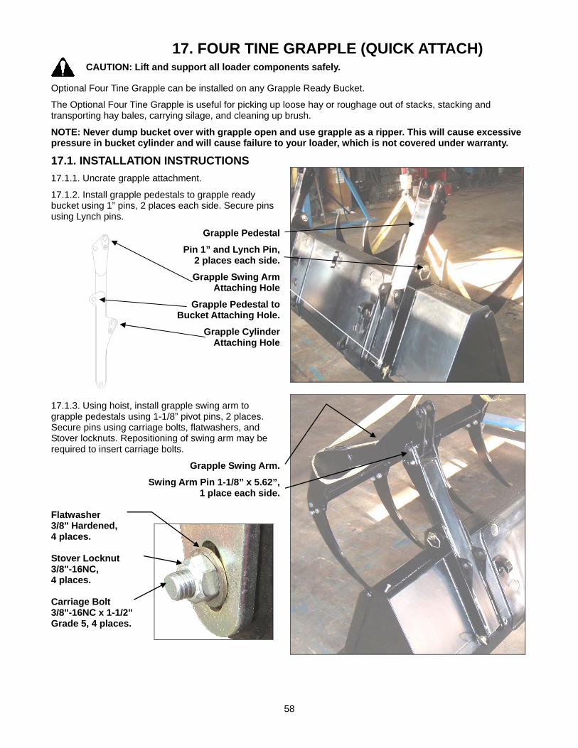
58
17. FOUR TINE GRAPPLE (QUICK ATTACH)
CAUTION: Lift and support all loader components safely.
Optional Four Tine Grapple can be installed on any Grapple Ready Bucket.
The Optional Four Tine Grapple is useful for picking up loose hay or roughage out of stacks, stacking and transporting hay bales, carrying silage, and cleaning up brush.
NOTE: Never dump bucket over with grapple open and use grapple as a ripper. This will cause excessive pressure in bucket cylinder and will cause failure to your loader, which is not covered under warranty.
17.1. INSTALLATION INSTRUCTIONS 17.1.1. Uncrate grapple attachment.
17.1.2. Install grapple pedestals to grapple ready bucket using 1” pins, 2 places each side. Secure pins using Lynch pins.
Grapple Pedestal
Pin 1” and Lynch Pin,2 places each side.
Grapple Swing ArmAttaching Hole
Grapple Pedestal toBucket Attaching Hole.
Grapple CylinderAttaching Hole
17.1.3. Using hoist, install grapple swing arm to grapple pedestals using 1-1/8” pivot pins, 2 places. Secure pins using carriage bolts, flatwashers, and Stover locknuts. Repositioning of swing arm may be required to insert carriage bolts.
Grapple Swing Arm.
Swing Arm Pin 1-1/8” x 5.62”, 1 place each side.
Flatwasher 3/8" Hardened, 4 places. Stover Locknut 3/8"-16NC, 4 places. Carriage Bolt 3/8"-16NC x 1-1/2" Grade 5, 4 places.

59
17.1.4. Install 4 tines to grapple swing arm using hex bolts, pair of hardened flatwashers (one on each side of tine), and locknuts.
Grapple Swing Arm
Hex Bolt 3/4"-10NC x 2-3/4” Grade 5, Flatwasher,
Tine, Flatwasher, Locknut 3/4", 3 places each.
Grapple Tine, 4 places.
17.1.5. Install cylinders to grapple using 1-1/8” x 3.65” pins in top holes and 1-1/8” x 5.62” pins in bottom holes. Secure pins using carriage bolts, flatwashers, and Stover locknuts.
NOTE: Grapple Cylinder ports face toward center of grapple.
Top Pin 1-1/8” x 3.65”
Grapple Cylinder, 2 places.
Bottom Pin 1-1/8” x 5.62” Flatwasher 3/8" Hardened, 4 places. Stover Locknut 3/8"-16NC, 4 places. Carriage Bolt 3/8"-16NC x 1-1/2" Grade 5, 4 places.
17.1.6. Install 90o fittings into grapple cylinders and rotate as shown, typical RH & LH sides.
Fitting 90o, rotate aligning with cylinder center line.
Fitting 90o, rotate toward
bucket slightly.

60
17.1.7. Install bulkhead tee fittings to bucket bracket as shown. Then install fittings and hoses as illustrated.
A. Bulkhead Tee Fitting, 2 places.
B. Flatwasher 3/4"
C. Bulkhead Nut
D. Fitting 90 o JIC 3/4" x 3/4"
E. Hose 3/8” x 38”, 2 places
F. Hose 3/8” x 30”, 2 places
G. Hose 3/8” x 33”, 2 places LH
H. Bulkhead Mount located on Bucket
J. Nylon Tie, to secure hoses
K. Hose Protector, located 10” from quick coupler end of hose.
L. Nylon Tie, 4 places.
M. Female Quick Coupler, attach to this hose.
N. Male Quick Coupler, attach to this hose.
G E F D F E
C H B A
E
F
L
K
M
N
17.1.8. Route hoses so they will not be damaged during loader operation.
17.1.9. Secure bulkhead tee to bucket by tightening "C" Bulkhead Nut on frontside and "B" Flatwasher on backside of "H" Bulkhead Mount located on Bucket.
10"

61
17.1.10. Connect bucket and grapple to loader quick attach as shown starting on page 50.
17.1.11. Connect grapple quick coupler to Loader Third Function Quick Couplers. Route hoses so they will not be damaged during loader use.
Female Quick Coupler with dust cover
Male Quick Coupler
17.2. THIRD FUNCTION QUICK COUPLERS NOTE: When bucket with grapple is disconnected from loader, always connect grapple quick couplers together. This will keep couplers clean and provide easier connecting of grapple hydraulics when reattaching to loader. CAUTION: To prevent potential injury, always close grapple when attachment is not in use.
17.2.1. Connect hoses so that grapple operates as shown below. Refer to illustration below and information as described on pages 21, 22 and 23.
17.2.2. If grapple does not operate as shown, switch hoses feeding quick couplers at Third Function Mount or at Bulkhead Tee Fittings.
17.3. OPERATING INSTRUCTIONS 17.3.1. When properly connected, the 3rd function valve should operate the grapple as follows. If not, switch 3rd function quick couplers around and try again.
(1) Press the number 1 left hand plus handle switch to open the grapple.
(2) Press the number 2 right hand plus handle switch to close the grapple.
17.3.2. When operating the loader with the grapple attachment, always remove the upper level of the stack first and approach the stack with the bucket level. The upper grapple teeth must be in the maximum open position. Never ram the grapple into material to be loaded to gain the desired depth. Close the upper grapple assembly only far enough to hold the material in place. Never force grapple tines into material using lift cylinder. Failure to follow these instructions could cause damage to loader components.

62
17.4. DISMOUNTING GRAPPLE FROM BUCKET
CAUTION: Lift and support all loader components safely.
17.4.1. Close grapple, relieve hydraulic pressure from system, and then disconnect the bucket and grapple from your loader quick attach. See information starting on page 53.
17.4.2. Loosen bulkhead nuts securing grapple hydraulic bulkhead tee fittings to bucket mount. Slide tee fittings out of mounting slots, 2 places.
Tee Fitting
Flatwasher Mounting Slot Bulkhead Nut
17.4.3. Connect a hoist, chain or sling to grapple assemble as shown.
NOTE: Make sure grapple is balanced and strap or chain is secured so it will not slide while grapple is being lifted and moved.
Hoist, Chain, or Sling
17.4.4. Raise the hoist slightly until grapple pins can be removed easily.
17.4.5. Remove 4 grapple pins slowly making sure grapple is balanced and is securely held in place by hoist.
Grapple Pins, 2 places each side
17.4.6. Using hoist lift the grapple off of the bucket. Store the grapple on a solid firm surface. Install dust plug into female quick coupler. DO NOT connect male and female coupler together when grapple is removed from the bucket. This will prevent cylinders from moving if a external force would accidentally be applied to the parked grapple.
Optional Grapple Extension

63
17.5. MOUNTING GRAPPLE TO BUCKET
CAUTION: Lift and support all loader components safely.
NOTE: Bucket should be disconnected from loader when attaching grapple to bucket.
17.5.1. Attach hoist with chain or sling to grapple.
NOTE: Make sure grapple is balanced and strap or chain is secured so it will not slide while grapple is being lifted and moved.
Hoist, Chain, or Sling
17.5.2. Raise the hoist slightly until grapple top hole is aligned with bucket. Install top pins and lynch pins, 1 place each side.
17.5.3. Rotate grapple rearward and align bottom holes. Install bottom pins and lynch pins, 1 place each side.
Top Pin and Lynch Pin,installed first,
1 place each side
Bottom Pin and Lynch Pin, installed second,
1 place each side.
17.5.4. Position bulkhead tee fittings over bucket attaching bar. Make sure flatwasher is on one side of mounting bar and bulkhead nut is on the opposite side of mounting bar. Position and secure by tightening bulkhead nuts.
Tee Fitting
17.5.5. Check hose routings make sure they are routed so they will not be damaged during loader operation. Then reattach the bucket and grapple to your loader quick attach following instructions starting on page 50.
Flatwasher Mounting Slot Bulkhead Nut

64
18. THIRD FUNCTION HOSE KIT 18.1. INSTALLATION INSTRUCTIONS 18.1.1. Unpackaged Third Function Hose Kit and then install color nylon tie to each end of each hose. This will allow identification of hoses after they have been routed through the boom frame.
18.1.2. Route 226” hoses on top of right hand boom arm and between right hand tilt cylinder and loader frame as shown. Make sure 5/16” coupler nut and 5/16” bridge nut are between hoses.
5/16” Coupler Nut.
Route hoses on top of boom arm.
5/16” Bridge Nut.
Route hoses between right hand tilt cylinder and loader frame as shown.
Right hand Tilt Cylinder.

65
18.1.3. Install o-rings to short end of bulkhead fittings. Then install bulkhead fitting into attaching plate and secure using bulkhead nut.
Bulkhead Nut
Attaching Plate
O-Ring, install on this end of Bulkhead Fitting
Bulkhead Fitting, Short End
Bulkhead Nut
Attaching Plate
O-Ring, install on this end of Bulkhead Fitting
Bulkhead Fitting, Short End
18.1.4. Install male and female quick coupler to end of bulkhead fitting with o-ring installed. Install male quick coupler to the rear bulkhead and the female quick coupler to the front bulkhead as shown.
Female Quick Coupler
Male Quick Coupler

66
18.1.5. Install dust plug in female quick coupler and install ¾” JICF 45° ends of 3rd function hoses to bulkhead adapters as shown.
3rd function hoses
Bulkhead Adapters
Dust Plug
18.1.6. Install sponge rubber on both ends of hose cover so sponge rubber sticks over edge approximately 1/8”.
Sponge Rubber, 1 place each end
Hose Cover
1/8”

67
18.1.7. Install 30” hose sock as shown. Slide hose sock up until it contacts 5/16” coupler nut on top of boom arm. Install hose cover on top of boom arm using 5/16” x 1” bolt, 5/16 lockwasher and 5/16” flatwasher for the coupler nut side and using 5/16” x 2.25” bolt, 5/16” lockwasher and 5/16” flatwasher for the bridge nut side.
5/16” x 1” bolt, 5/16 Lockwasher, 5/16” Flatwasher,
1 place each
Sponge Rubber installed on end of Hose Cover
30” Hose Sock slides up until it contacts bridge nut
Hose Cover
18.1.8. Secure two 226” hoses to base loader lift circuit hoses as shown with plastic tie strap.
Base Loader Lift Circuit hoses
3rd Function 226” hoses
Plastic Tie Strap
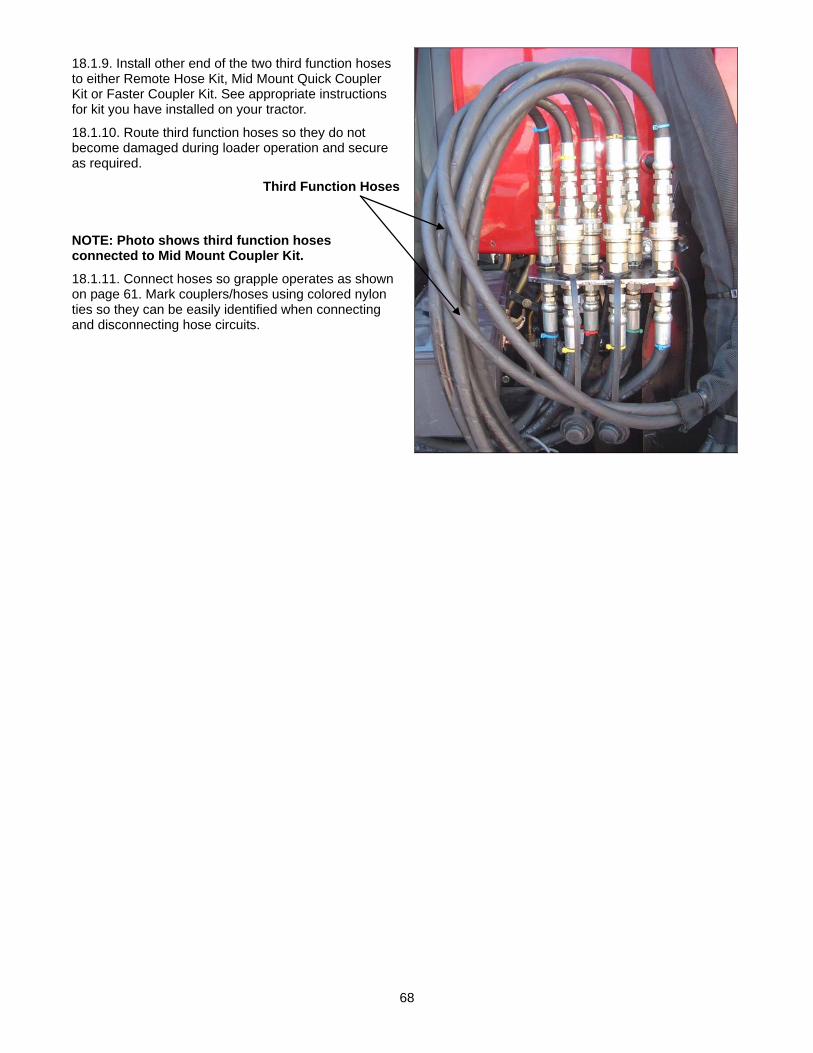
68
18.1.9. Install other end of the two third function hoses to either Remote Hose Kit, Mid Mount Quick Coupler Kit or Faster Coupler Kit. See appropriate instructions for kit you have installed on your tractor.
18.1.10. Route third function hoses so they do not become damaged during loader operation and secure as required.
Third Function Hoses
NOTE: Photo shows third function hoses connected to Mid Mount Coupler Kit.
18.1.11. Connect hoses so grapple operates as shown on page 61. Mark couplers/hoses using colored nylon ties so they can be easily identified when connecting and disconnecting hose circuits.

69
19. OPTIONAL MID-MOUNT FASTER COUPLER KIT
NOTE: Optional Mid-Mount Faster Coupler Kit is equipped with 1 lever connect and disconnect of hydraulic circuits.
19.1. OPERATION 19.1.1. Refer to following instructions along with the instructions included in the handbook shipped with your Multifaster system.
19.2. CONNECTION & DISCONNECTION 19.2.1. Connection and disconnection with Multifaster system are very simple and easy operations.
19.2.2. Simultaneous connection is achieved, thanks to a lever linked to cams allowing the progressive moving of the mobile part to the fixed one.
19.2.3. Multifaster system is suitable for connection and disconnection under pressure.
19.2.4. Anyway, for safety reasons it is always advisable to decrease the internal pressure before this operation.

70
19.3. CONNECTION PHASE 19.3.1. Pick-up the dust
cover of the fixed part.
19.3.2. Push the safety lock button.
19.3.3. In the same time, lift up the lever.
19.3.4. Put the mobile part on the fixed one.
19.3.5. Engage the reference pins in the proper holes.
19.3.6. Lean the rolling pins on the cams profiles.
19.3.7. Turn down the lever till stop.
19.3.8. Connection is achieved once the safety button releases automatically.
19.4. DISCONNECTION PHASE 19.4.1. Hold in a firm way
the lever.
19.4.2. Push the safety button.
19.4.3. Lift up the lever till the rolling pins are free from the cams profiles.
19.4.4. Place the mobile part on the suitable support.
19.4.5. Close the dust protection on the fixed part.

71
19.5. IMPORTANT WARNINGS 19.5.1. Each Multifaster is provided of a sticker pointing out the most important things to remember when using this product.
This symbol reminds that the Multifaster system works with high pressure inside. For this reason it is always advisable to use the product in a proper way in order to prevent damages to people and machines.
This symbol reminds to carefully read this INSTRUCTION SECTION before each installation and use of Multifaster system.
This symbol reminds that a safety lock is assembled on the product. To disconnect the Multifaster it is always necessary to push the safety lock button. Do not force the lever without pushing the safety lock button.
This symbol reminds that, before each connection, it is advisable to ensure to clean the mating surface of the Multifaster fixed part, mobile part and the reference pins. Dirt inclusions may cause damages to seals with consequent leakages form the Multifaster.
19.6. ORDINARY MAINTENANCE 19.6.1. Multifaster is a complex system, designed to work with high pressure inside, in a dusty environment and exposed to atmospheric agents. For this reason it is very important to schedule an ordinary maintenance activity, carried out day by day, before each use of the Multifaster.
19.6.2. By following the suggestions below, the service life of the product will be increased and the Multifaster will be allowed to work in a better way in every situation.
19.6.3. Before each connection, ensure to carefully clean the mating surfaces of the fixed part, of the mobile part, and the reference pins.
19.6.4. Lubricate periodically all the moving components (see the picture).
19.6.5. Once the Multifaster is disconnected, please close the automatic dust cap to prevent dirt inclusions and to keep the flat surface of the fixed part clean.
19.6.6. Place the Multifaster mobile part on the suitable support when it is not used.

72
20. OPTIONAL COMFORT DRIVE 20.1. INSTRUCTIONS 20.1.1. Transporting heavy loads over rough terrain can heavily stress the tractor and loader it reduces stability and causes discomfort to the operator. If you equip your loader with comfort drive you will reduce the stresses in the tractor and loader, increase tractor stability and operator comfort.
20.1.2. The KMW Comfort Drive system is made up of a two single piston accumulator built into one unit. The smaller side of the accumulator is connected to the Rod end of the lift cylinder and the larger side of the accumulator is connected to the base end of the lift cylinders. When charged properly these accumulators allow the loader lift cylinders to move a short distance when carrying a load over a rough surface. This movement reduces the shock stress to the tractor, loader and operator and increases stability of unit.
20.1.3. The KMW Comfort Drive system can be turned on and off from your tractor seat. This allows the operator to turn off this system when digging with loader, when handling loads in sheds and any time operator need precise loader control. It can then be turned back on when the operator is traveling across rough terrain.
20.2. OPERATION CHARACTERISTICS 20.2.1. When the comfort drive system is turned on the loader may raise or lower slightly depending on the pressure the system was under at the time the operator turns the system on or off.
20.2.2. When dumping a load with the comfort drive system on the loader will raise slightly when the load is removed from your attachment. When in close areas such as unloading in a shed always turn off the comfort drive system.
20.2.3. Photo shows basic location of comfort drive dual cavity accumulator.
1860 - Comfort Drive Dual Cavity Accumulator located inside boom crosstube. NOTE: Your comfort drive installation may differ slightly
from photo see following instructions.
20.2.4. To improve performance of comfort drive always turn comfort drive on before loading your bucket or attachment. This will reduce cavitation in lift circuit allowing comfort drive to give you a smooth ride.
WARNING: Always turn on Accumulator (Comfort Drive), lower loader/attachment to ground and relieve hydraulic pressure from system, before servicing unit. Failure to follow these instructions could result in personal injury.
CAUTION: Caution should be taken when turning on the comfort drive system make sure loader is away from personnel, power lines, roofs or any other structure because loader will lower or raise slightly until loader cylinders and accumulator pressures are equalized .
WARNING: Never turn comfort drive on while tractor is moving. Loader movement could cause loader to lower causing attachment or material being moved to contact ground. Failure to follow these instructions could result in personal injury or property damage.
CAUTION: When servicing the loader or leaving operator's seat for any reason, always: Lower the loader to ground. Turn on Comfort Drive, if equipped Apply the parking brake securely Shut off the engine Turn on tractor switch so Comfort Drive Solenoid is energized. Release all hydraulic pressure in all circuits by moving hydraulic control lever or levers in all positions. Return lever or levers to neutral position. Turn off tractor switch and remove the key.
CAUTION: • Gas pressurized vessel • Charge with Nitrogen only • Do not disconnect oil line before releasing oil pressure • Do not Disassemble accumulator before releasing oil and gas pressure
73
20.3. OPERATION AND MAINTENANCE 20.3.1. Comfort Drive accumulators must not be used with any hazardous fluid. Only petroleum base fluids are to be used. It is essential the user follow strictly the instructions as follows.
20.3.2. Maximum hydraulic working pressure for accumulators is 3000 PSI. DO NOT EXCEED this limit.
20.3.3. Temperature operating range is MINUS (-) 20˚ F. to PLUS (+) 200˚F. with the petroleum based fluids.
20.3.4. KMW does not accept any responsibility for damage to persons or property or for any consequences e.g.: loss of operation, resulting from the failure to observe the instructions set out in this manual.
20.4. DELIVERY 20.4.1. Accumulators are delivered with no nitrogen pre-charge, however, only a very low residual nitrogen charge may remain in the accumulator from the factory testing.
20.5. HANDLING 20.5.1. Suitable lifting gear should be used for the weight of the accumulator(s) and the gas charging valve must be protected from an external impact.
20.6. STORAGE 20.6.1. The storage location must be kept cool and dry. The accumulator must not be exposed to heat or flames.
20.7. INSTALLATION 20.7.1. Prior to installation, a visual inspection should be carried out for detection of any damage.
20.7.2. For maximum seal life, fluid should be filtered to 10 micron or less.
20.8. PRECAUTIONS 20.8.1. Beware of sudden release of pre-charge pressure. When necessary, discharge the gas side of the accumulator using a charging and gauging assembly.
20.8.2. Allow adequate space above the gas valve permitting access for the charging and gauging apparatus.
20.8.3. Leave caution labels in clear view and legible.
20.8.4. Install so no abnormal force is brought to bear on the plumbing connected either directly or indirectly to the accumulator.
20.8.5. Secure the accumulator tube to a support using U-bolt mounting brackets preventing its movement in the event of failure of its connection to the hydraulic installation.
20.8.6. Connect the accumulator to the hydraulic circuit using appropriate connecting devices.
20.9. STRICTLY PROHIBITED 20.9.1. Welding or riveting any parts or assemblies to the accumulator for attachment or otherwise.
20.9.2. Carrying out any operation that could affect the mechanical properties of the accumulator.
20.9.3. Using the accumulator as a structural element, subjecting it to any stress or external physical loading.
20.9.4. Improper tightening of “U” bolt clamps for mounting the accumulator and causing distortion of the tube and binding between the piston and tube.

74
20.10. ASSEMBLY INSTRUCTIONS
20.11. ASSEMBLE PISTON 20.11.1. Lubricate all Seals before assembly.
20.11.2. Assemble T-seal in the front groove of the Piston.
20.11.3. Assemble Backup on both sides of the T-Seal.
20.11.4. Assemble Wear Ring in the middle groove of Piston.
20.11.5. Assemble Wear Ring in the rear groove of Piston
20.11.6. Install Piston Assembly into Tube Assembly.
20.12. ASSEMBLE END CAP 20.12.1. Lubricate all Seals before Assembly.
20.12.2. Assemble Backup as shown into groove of End Cap.
20.12.3. Assemble O-Ring behind Backup.
20.12.4. Place Nylon Plug in side hole of End Cap as shown.
20.12.5. Place End Cap in end of Tube Assembly and thread into place firmly with Spanner Wrench.
20.13. ASSEMBLE CHARGING VALVE 20.13.1. Thread Charging Valve into End Cap. Torque 100-110 in. lb.
20.13.2. Thread Valve Cap into End Cap.
20.13.3. Place Shipping Plug in the end of Valve Cap to complete assembly.
20.14. NITROGEN PRE-CHARGING 20.14.1. Gas pre-charging can be performed before or after the installation of the accumulator in the hydraulic circuit and should be performed only by qualified personnel. Safety equipment such as gloves to protect from handling of the cold gas and a face shield and safety glasses are a must.
Figure 1Loosen this nut to charge accumulator

75
CAUTION: EXPLOSIVE - Use only oxygen-free, dry nitrogen gas with a minimum purity of 99.95%. The use of compressed air as from an air compressor or oxygen is extremely dangerous and is strictly prohibited.
20.14.2. Mark out a safe working area and adopt a position, which is not inline with the accumulator ports.
20.14.3. Charge the accumulator using the charging and gauging assembly as follows below.
20.14.4. Do not exceed the maximum working pressure and temperature ranges as previously specified.
20.14.5. Avoid charging and discharging repeatedly to minimize the risk of damage to the piston.
20.14.6. Check for leaks from the charging valve, e.g.: by using soapy water.
20.15. USE OF CHARGING AND GAUGING ASSEMBLY WHEN PRE-CHARGING See Figure 1 on page 74.
20.15.1. Both sides of the 1860 loader accumulator will need to be precharged as follows: Large side of accumulator connected to base end of lift pre-charge to 750 PSI. Small side of accumulator connected to the rod end of lift pre-charge to 600 PSI.
CAUTION: Be sure main supply valve on the nitrogen bottle is securely closed. Briefly crack open this valve to dislodge any contaminants within the valve, and then apply the appropriate gages/regulator assembly securely to the main supply valve on the bottle. Bottle must be securely retained upright to avoid it falling over.
20.15.2. Obtain a Complete Charging and Gauging Assembly (consists of Charging Hose Assembly- [swivel connector, 10 ft. hose assembly], and Portable Mount Body Assembly- [appropriate-PSI gauge, bleeder valve, air chuck, and tank valve]. Follow your instructions for your Charging & Gauging Assembly. Below are generic pre-charging instructions.
20.15.3. Remove the mounting rod and then the metal valve cap from accumulator.
20.15.4. Remove yellow protective valve cap and/or mounting rods from the valve stem and attach charging & gauging assembly to charging valve.
20.15.5. Loosen lock nut on charging valve approximately 3 turns.
20.15.6. Use regulator on nitrogen bottle; open nitrogen valve.
20.15.7. Charge accumulator to specified pre-charge pressure. The "T" handle on the charging & gauging assembly will need to be tightened if the charging valve has a valve core.
20.15.8. Tighten lock nut on charging valve and allow pressure to stabilize for several minutes, and then repeat steps 5, 6, & 7.
20.15.9. Retighten lock nut, open bleeder valve to bleed hose pressure and remove charging & gauging assembly.
20.15.10. Apply the yellow protective cap to the valve stem.
20.15.11. Apply the metal valve cap to the accumulator end cap.
20.15.12. Accumulator can be charged in boom crosstube by using an additional extension.
20.16. HYDRAULIC PRESSURIZING 20.16.1. Ensure that the hydraulic working pressure never exceeds the maximum pressure of 3000 PSI.
20.17. MAINTENANCE 20.17.1. Check the gas pre-charge pressure regularly during the first few weeks of operation, and then at suitable intervals afterwards based on this initial experience. Check when the hydraulic fluid pressure is at 0 (zero) PSI.
20.17.2. Pre-charge pressure and ambient temperature should be recorded at installation and nitrogen gas pre-charge pressure should be checked at least once during the first week of operation. If no loss of gas pressure is noted, it should be rechecked in approximately 4 months and thereafter, checked annually.

76
20.17.3. Perform a visual examination of the accumulator periodically in order to detect any early signs of deterioration, such as corrosion, deformation, etc.
20.17.4. After allowing for any appreciable temperature variation, generally an increase in pre-charge pressure indicates a gradual leakage of fluid into the gas side. Conversely, a decrease in pre-charge pressure means leakage of gas into the fluid side. The amount of leakage will depend upon piston velocity.
20.17.5. Before removal, it is vital to ensure that there is no residual hydraulic pressure in the accumulator. Discharge the gas side of the accumulator using a charging and gauging assembly and drain fluid completely from accumulator before carrying out any maintenance operations.
20.17.6. Do not use automotive valve cores to replace the charging valve core.
20.18. COMFORT DRIVE INSTALLATION INSTRUCTIONS
Figure 1
Hose 3/8" x 16"
Hose 3/8" x 28"
Must connect to Base End ofLift Cylinder
Long end must connect to base end of lift cylinder
Connect these wires.
Route wire through this hole to rear of boom. Use fish tape to pull wire.
Must connect to Rod End of Lift Cylinder
Hose 3/8" x 12"
Pre-charge long end of accumulator to 750 PSI (Connect to Base end Lift Circuit)
Pre-charge short end of accumulator to 600 PSI (Connect to Rod end Lift Circuit)
Install O-ring on short side of Bulkhead fitting
To charge accumulator remove mounting rod from accumulator. To expose valve stem see section 20.15

77
20.18.1. Remove hose cover from loader crosstube and install solenoid block to hose cover as shown using two carriage bolt ¼”-20 x 2.25”, ¼”-20 stover hex locknuts and solenoid strap. Install ¾” ORBM x ¾” JICM 90° fitting in solenoid block as shown.
Solenoid Block
Solenoid Strap
Carriage Bolt ¼”-20 x 2.25”, Stover Hex Locknut ¼”-20, 2 places
¾” ORBM x ¾” JICM 90° fitting
20.18.2. Install O-ring to short side of bulkhead fitting and install in lift rod (short end) port of accumulator.
Short side of Accumulator
Bulkhead fitting with O-ring installed in short side of Accumulator
20.18.3. Insert accumulator in upper section of loader crosstube making sure that bulkhead fitting installed in the lift rod (short end) port is located on the right hand side of loader as shown. Accumulator will have to be rotated as shown so bulkhead fitting will fit in loader crosstube. NOTE: It may be necessary to remove parking stands from loader crosstube to make insertion of accumulator easier.
Bulkhead fitting located on right hand side of accumulator and rotated to fit in crosstube
LH Boom Arm

78
20.18.4. When accumulator is centered in crosstube rotate accumulator so bulkhead fitting fits up through hole in crosstube. Secure accumulator to loader using accumulator mount plate, 2 places, hex head cap screw 3/8”-16 x 2.25”, 3/8” flatwasher and 3/8” lockwasher, 4 places as shown. Make sure bulkhead fitting remains centered in boom crosstube hole while tightening hardware. Secure accumulator to accumulator plates by installing 5/8”-18 accumulator nuts on ends of accumulator.
Hex Head Cap Screw 3/8”-16 x 2.25”, 3/8” Flatwasher, 3/8” Lockwasher, 4 places
Accumulator Plate
5/8”-18 Accumulator Nut
20.18.5. Install 2.7” long fitting ¾” ORBM x ¾” JICM into the remaining port of the accumulator.
2.7” long fitting ¾” ORBM x ¾” JICM
Boom Crosstube hole
20.18.6. Remove two caps from tees on lift cylinder circuits.
Rod end of Lift Cylinder
Base end of Lift Cylinder
Remove these caps

79
20.18.7. Install 16” hose assembly 11/16” FFF x ¾” JIFC 90° to bulkhead fitting installed in the accumulator. Leave the other end of the hose loose for now.
16” Hose Assembly 11/16” FFF x ¾” JIFC 90° connected to Bulkhead fitting
20.18.8. Reinstall hose cover hardware as shown.
Hose Cover reinstalled
20.18.9. Install 28” hose assembly 11/16” FFF x ¾” JIFC to base end lift circuit tee and to ¾” ORBM x ¾” JICM 90° fitting installed in solenoid block. Route hose as shown. Install remaining end of 16” hose assembly 11/16” FFF x ¾” JIFC 90° to rod end lift circuit tee as shown.
Connect 16” hose to Tee fitting connected to rod end of Lift Cylinder
28” hose assembly 11/16” FFF x ¾” JIFC (Lift
Cylinder base end circuit)
¾” ORBM x ¾” JICM 90° fitting
20.18.10. Install 12” hose assembly ¾” ORBM x ¾” JICF 90° to solenoid block and to 2.7” long fitting ¾” ORBM x ¾” JICM as shown. Route hose and secure with plastic tie straps in locations shown.
12” hose assembly ¾” ORBM x ¾” JICF 90°
Solenoid Block
Secure with Plastic Tie Straps

80
20.18.11. Route and mount solenoid ground wire to carriage bolt as shown.
Mount Solenoid Ground Wire to Carriage Bolt
Pre-charge Valve Pre-charge Valve Short End of Accumulator to 600 PSI Long End of Accumulator to 750 PSI
Rod End Base End Long End of of Lift Circuit of Lift Circuit Accumulator
20.18.12. Route fish tape from rear of loader arm through hole in boom arm; attach fish tape to solenoid wire.
Attach Fish Tape to this end if pulling wire toward rear of loader.
Weather Disconnect
End
Charging Valve

81
20.18.13. Pull solenoid wire carefully through loader boom frame. Route so it will not be damaged during loader operation. Connect this wire to solenoid wire.
20.18.14. Cover solenoid wire with plastic wire cover.
20.18.15. Secure wire protector using nylon ties on each end.
NOTE: Plastic wire protector should extend through hole in boom arm to prevent damage to wire.
Route and connect wire as shown
20.18.16. Install universal switch mount in location that allows operator to activate comfort drive easily. This switch may be mounted on your loader control handle as shown or it can be mounted in some other convenient place.
NOTE: Make sure switch location is convenient to operator and it does not interfere with any other tractor control. Refer to illustration below for switch mounting and assembly instructions.
20.18.17. Route fuse wire from comfort drive switch to hot wire of tractor that is activated only when tractor switch is turned on. This will insure that solenoid is deactivated when tractor is shut off and will prevent comfort drive from being turned on when tractor is shut off.
Comfort Drive Switch
Switch Mount
U-Clamped to Loader
Control Handle

82
20.18.18. Route comfort drive switch wire with weather connector outside of cab and connect this wire to weather proof connector on wire running to comfort drive solenoid.
NOTE: Route wiring so it will not be damaged during loader operation.
20.18.19. Install 5-amp fuse into fuse holder.
NOTE: When mounting and dismounting loader, this connector must be connected and disconnected.
20.18.20. Pre-charge accumulator as described in section 20.15 of this manual. Always follow all safety procedures and only pre-charge using Nitrogen.
Connect these
Solenoid Wire to Accumulator
Comfort Drive Switch Wire
Comfort Drive Switch
U-Bolts
Switch MountPlate
Switch Wire Connector
Wire to Solenoid
Weather Connector
Hot Wire to Tractor 5-amp Fuse and
Fuse Holder
Switch Wire
Connector
Rear View of Switch
Front View of Switch

83
20.19. DISASSEMBLY OF ACCUMULATOR FOR SERVICING Refer to Figure 1 on page 74.
NOTE: For disassembly it is good practice to disassemble and reassemble accumulators in a clean area to keep all parts free of foreign matter. Refer to the illustrated Assembly Instruction.
20.19.1. Follow instructions for checking pre-charge, and then release all hydraulic and pre-charge pressure.
20.19.2. Drain balance of hydraulic fluid remaining in accumulator when it is disconnected from system.
20.19.3. Remove gas charging valve.
20.19.4. Remove end cap by using a spanner wrench and unscrewing counter-clockwise.
20.19.5. To remove accumulator pistons having a blind-end at the fluid end, a sufficient length of 3/8-16 all-threaded bolt material should be attached to the threaded hole at the center of the piston. This bolt is then used in pulling the piston from the tube. Care should be taken not to damage piston or seals when passing through the threaded portion of the tube.
20.19.6. Examine piston and end cap seals for signs of damage. Inspect “T” ring seal closely for score marks or cuts. Excessive cuts should warrant a very thorough examination of metal surfaces for damage.
20.19.7. Clean all metal parts with hydraulic fluid and dry with a soft clean towel.
20.19.8. Inspect tube bore for damage due to foreign contaminant particles in the fluid system. All scratches must be removed from the cylinder bore. Examine threads in tube. Remove any sharp shavings and clean well.
20.19.9. Inspect piston for damage due to bottoming.
20.20. RE-ASSEMBLY OF ACCUMULATOR FOR SERVICING Refer to Figure 1 on page 74.
20.20.1. It is recommended that all seals and wear rings be replaced prior to re-assembly.
20.20.2. Wet seals with hydraulic system fluid and carefully assemble into piston groove. Assure that seals are not twisted.
20.20.3. Insert back-ups carefully so as not to stretch more than necessary.
20.20.4. Apply a light coat of petrolatum to all threads inside tube.
20.20.5. Assemble piston carefully into tube without cocking to avoid damage to the piston and/or seals on the threads. With bolt attached to the piston, align piston with tube and with a hammer, tap the outer end of the bolt to drive the piston assembly inward. Special care must be taken to avoid pinching the back-ups.
20.20.6. Assemble back-up and o-ring onto the end cap groove per illustration. The back-up ring should be nearest the threaded portion.
20.20.7. Apply a light coat of petrolatum to the seals of the end cap and thread end cap into the tube until it bottoms out. Tighten firmly using a spanner wrench.
20.20.8. The accumulator can now be pre-charged per instructions.

84
21. OPTIONAL 2-WAY HYDRAULIC SELF LEVELING
CAUTION: Never disassemble this self-leveling valve unless you are a factory trained mechanic. Failure to follow these instructions will void warranty and could cause the self leveling valve to operate incorrectly. If you need service on this valve return complete unit to KMW dealer for service.
CAUTION: When servicing the loader or leaving operator's seat for any reason, always: Lower the loader to ground. Turn on Comfort Drive, if equipped Apply the parking brake securely Shut off the engine Turn on tractor switch so Comfort Drive Solenoid is energized. Release all hydraulic pressure in all circuits by moving hydraulic control lever or levers in all positions. Return lever or levers to neutral position. Turn off tractor switch and remove the key.
IMPORTANT: This hydraulic self leveling option MUST only be used with hydraulic kits as specified in the KMW sales manual. Use of this hydraulic self leveling kit with any other hydraulic kit than the KMW approved kits is strictly forbidden. Failure to follow these instructions could cause the hydraulic self leveling to perform erratically which could cause damage or personnel injury.
21.1. OPERATING INSTRUCTIONS WHEN INSTALLED ON LOAD SENSE AND CLOSED CENTER HYDRAULIC SYSTEMS IMPORTANT: With hydraulic self leveling, bucket or attachment angle can be adjusted throughout raising and lowering cycles of loader.
CAUTION: When using a loader be alert of bucket or attachment position at all times. Loader in raised position with bucket or attachment rolled back can dump material onto tractor causing damage or injury to tractor and/or operator.
21.1.1. The hydraulic self leveling system maintains the orientation of the loader attachment relative to the plane of the tractor tires as set by the operator using the loader attachment cylinders. As long as the attachment cylinders are not operated, the orientation of the attachment will remain when the lift cylinders are functioned. The hydraulic self leveling function is controlled by a manifold block mounted on the outside of the right hand loader bearing box.
IMPORTANT NOTE: Self leveling of the KMW loader is accomplished by utilizing a hydraulic self leveling valve. Since oil flow is required to allow this valve to function correctly, the tractor must operate at 1500 RPM or above. Following these instructions allows self level valve to function consistently during loader operation.
21.1.2. If the operator feathers the loader valve the self leveling valve will not level during the raise cycle. This is caused by the limited oil flow coming out of the loader valve. Always fully stroke the loader valve when raising the unit.
21.1.3. When lowering a loaded attachment feathering the load down will allow consistent leveling of the load.
21.1.4. With heavy loads on unit the loader may bounce when lowering load. Running tractor at high rpm will minimize the bounce you may see.
21.1.5. When loader is equipped with self level valve, the operator will see some cycle time speed reductions. However the operator does not have to move bucket manually during cycling of the loader which speeds up the overall operation.
21.1.6. Lowering the load with 2-way self leveling requires metering the return oil from the valve to maintain self leveling operation. This will result in an increased lowering time.
21.1.7. Always let tractor hydraulic oil warm up to operating temperature before using the unit.
21.1.8. Lowering loader with attachment rolled back against rollback stops will cause cylinder cavitation. If loader is then raised, self leveling function will be delayed. NOTE: Lowering loader with bucket rolled off of rollback stops will reduce cavitation and provide more consistent leveling.
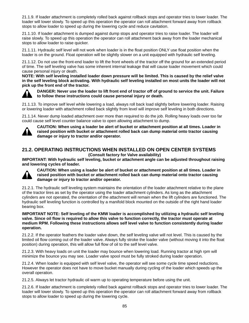
85
21.1.9. If loader attachment is completely rolled back against rollback stops and operator tries to lower loader. The loader will lower slowly. To speed up this operation the operator can roll attachment forward away from rollback stops to allow loader to speed up during the lowering cycle and reduce cavitation.
21.1.10. If loader attachment is dumped against dump stops and operator tries to raise loader. The loader will raise slowly. To speed up this operation the operator can roll attachment back away from the loader mechanical stops to allow loader to raise quicker.
21.1.11. Hydraulic self level will not work when loader is in the float position ONLY use float position when the loader is on the ground. Float operation will be slightly slower on a unit equipped with hydraulic self leveling.
21.1.12. Do not use the front-end loader to lift the front wheels of the tractor off the ground for an extended period of time. The self leveling valve has some inherent internal leakage that will cause loader movement which could cause personal injury or death. NOTE: With self leveling installed loader down pressure will be limited. This is caused by the relief valve in the self leveling block activating. With hydraulic self leveling installed on most units the loader will not pick up the front end of the tractor.
DANGER: Never use the loader to lift front end of tractor off of ground to service the unit. Failure to follow these instructions could cause personal injury or death.
21.1.13. To improve self level while lowering a load, always roll back load slightly before lowering loader. Raising or lowering loader with attachment rolled back slightly from level will improve self leveling in both directions.
21.1.14. Never dump loaded attachment over more than required to do the job. Rolling heavy loads over too far could cause self level counter balance valve to open allowing attachment to dump.
CAUTION: When using a loader be alert of bucket or attachment position at all times. Loader in raised position with bucket or attachment rolled back can dump material onto tractor causing damage or injury to tractor and/or operator.
21.2. OPERATING INSTRUCTIONS WHEN INSTALLED ON OPEN CENTER SYSTEMS (Consult factory for Valve availability)
IMPORTANT: With hydraulic self leveling, bucket or attachment angle can be adjusted throughout raising and lowering cycles of loader.
CAUTION: When using a loader be alert of bucket or attachment position at all times. Loader in raised position with bucket or attachment rolled back can dump material onto tractor causing damage or injury to tractor and/or operator.
21.2.1. The hydraulic self leveling system maintains the orientation of the loader attachment relative to the plane of the tractor tires as set by the operator using the loader attachment cylinders. As long as the attachment cylinders are not operated, the orientation of the attachment will remain when the lift cylinders are functioned. The hydraulic self leveling function is controlled by a manifold block mounted on the outside of the right hand loader bearing box.
IMPORTANT NOTE: Self leveling of the KMW loader is accomplished by utilizing a hydraulic self leveling valve. Since oil flow is required to allow this valve to function correctly, the tractor must operate at medium RPM. Following these instructions allows self level valve to function consistently during loader operation.
21.2.2. If the operator feathers the loader valve down, the self leveling valve will not level. This is caused by the limited oil flow coming out of the loader valve. Always fully stroke the loader valve (without moving it into the float position) during operation, this will allow full flow of oil to the self level valve.
21.2.3. With heavy loads on unit the loader may bounce when lowering load. Running tractor at high rpm will minimize the bounce you may see. Loader valve spool must be fully stroked during loader operation.
21.2.4. When loader is equipped with self level valve, the operator will see some cycle time speed reductions. However the operator does not have to move bucket manually during cycling of the loader which speeds up the overall operation.
21.2.5. Always let tractor hydraulic oil warm up to operating temperature before using the unit.
21.2.6. If loader attachment is completely rolled back against rollback stops and operator tries to lower loader. The loader will lower slowly. To speed up this operation the operator can roll attachment forward away from rollback stops to allow loader to speed up during the lowering cycle.

86
21.2.7. If loader attachment is dumped against dump stops and operator tries to raise loader. The loader will raise slowly. To speed up this operation the operator can roll attachment back away from the loader mechanical stops to allow loader to raise quicker.
21.2.8. Hydraulic self level will not work when loader is in the float position ONLY use float position when the loader is on the ground.
21.2.9. Do not use the front-end loader to lift the front wheels of the tractor off the ground for an extended period of time. The self leveling valve has some inherent internal leakage that will cause loader movement which could cause personal injury or death. NOTE: With self leveling installed loader down pressure will be limited. This is caused by the relief valve in the self leveling block activating. With hydraulic self leveling installed on most units the loader will not pick up the front end of the tractor.
DANGER: Never use the loader to lift front end of tractor off of ground to service the unit. Failure to follow these instructions could cause personal injury or death.
21.2.10. To improve self level while lowering a load, always roll back load slightly before lowering loader. Raising or lowering loader with attachment rolled back slightly from level will improve self leveling in both directions.
21.2.11. Never dump loaded attachment over more than required to do the job. Rolling heavy loads over too far could cause self level counter balance valve to open allowing attachment to dump.
21.3. INSTALLATION INSTRUCTION FOR LOAD SENSE HYDRAULIC SYSTEMS 21.3.1. Position the tractor and loader on a hard level surface.
21.3.2. Install hydraulic self leveling block to RH loader bearing box using two 3/8”-18 x 1” Hex Bolts and 3/8” Lockwashers. Make sure ports 1-4 with 7/8” ORBM x ¾” JICF fittings are facing down.
Hydraulic Self-Leveling Block
Right Hand Bearing Box

87
CAUTION: Escaping hydraulic fluid under pressure can have sufficient force to penetrate skin, causing serious personal injury. Before disconnecting lines, be sure to relieve all pressure.
Before applying pressure to system, be sure all connections are tight and that lines, tubes, and hoses are not damaged.
Fluid escaping from a very small hole can be almost invisible. Use a piece of cardboard or wood, rather than hands, to search for suspected leaks.
If injured by escaping fluid, see a doctor at once. Serious infection or reaction can develop if proper medical treatment is not administered immediately.
Cardboard Hydraulic Line Magnifying Glass
21.3.3. To prevent personal injury, work loader valve handle/handles to relieve all hydraulic fluid pressure in lines.
21.3.4. Remove Nylon ties and reposition hose protectors to expose hose connections.
21.3.5. Both hose ends should be marked with identical color ties.
21.3.6. Disconnect loader valve hoses from loader hoses. NOTE: Make sure Orifice Assembly stays with loader valve hose.
NOTE: If this is a new loader installation, refer to your Mid Mount Coupler Kit or Faster Handle Coupler Kit installation instructions for information on how to connect extension hoses before proceeding with step 21.3.7.
Loader hoses.
Loader Valve hoses.

88
21.3.7. The hydraulic self-leveling valve comes pre-assembled from the Factory with the fittings installed and color ties identifying each circuit.
21.3.8. Route valve hoses to self-leveling valve as shown to make sure they will not contact front tires during loader operation.
21.3.9. Connect valve hoses to bottom side of self-leveling valve matching color ties and tighten these fittings. Make sure Orifice Assembly is fitted as shown.
IMPORTANT: Matching nylon tie colors during installation will insure Self Leveling valve will operate correctly.
21.3.10. Connect loader hose ends to top side of self-leveling valve matching color ties and tighten these fittings. IMPORTANT: Matching nylon tie colors during installation will ensure self leveling valve will operate correctly.
21.3.11. Position hose protector and secure using nylon tie.
Existing Loader Hoses Routed and Connected to
Top of Self-Leveling Valve.
Nylon Tie
Hose Protector
Loader Valve Hoses Routed and Connected to
Bottom of Self-Leveling Valve.
Orifice installed in fitting installed on hose marked
with Red color tie.
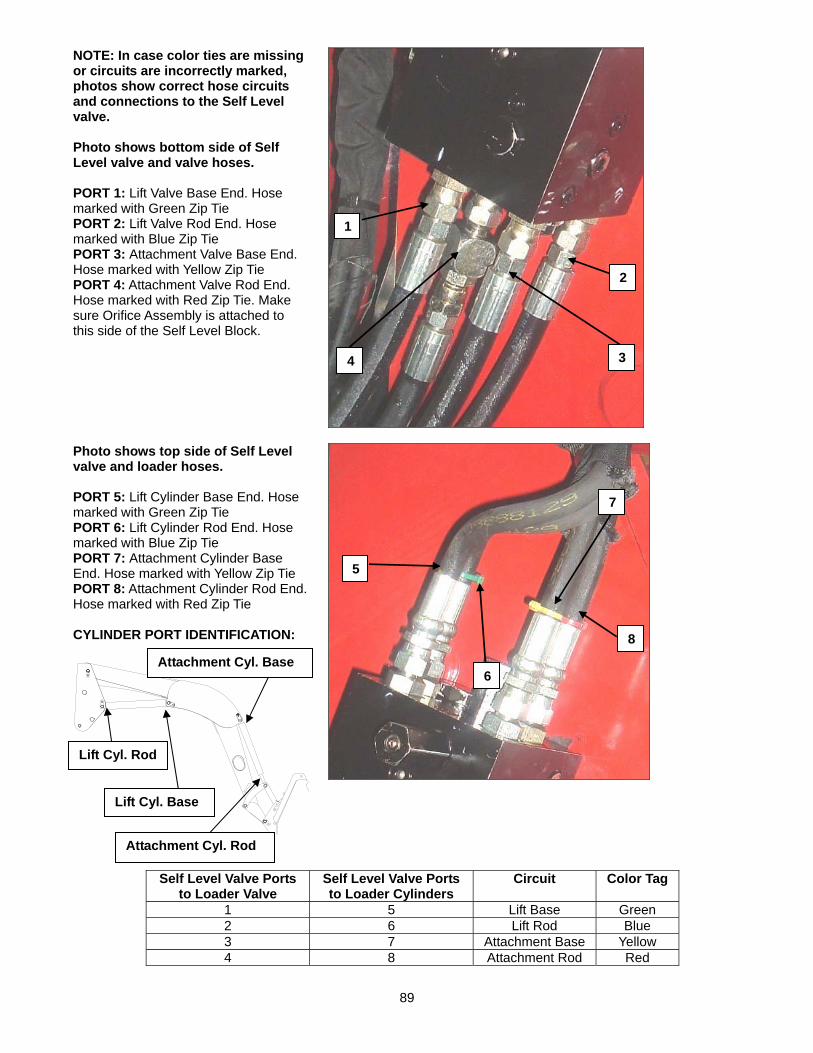
89
NOTE: In case color ties are missing or circuits are incorrectly marked, photos show correct hose circuits and connections to the Self Level valve. Photo shows bottom side of Self Level valve and valve hoses. PORT 1: Lift Valve Base End. Hose marked with Green Zip Tie PORT 2: Lift Valve Rod End. Hose marked with Blue Zip Tie PORT 3: Attachment Valve Base End. Hose marked with Yellow Zip Tie PORT 4: Attachment Valve Rod End. Hose marked with Red Zip Tie. Make sure Orifice Assembly is attached to this side of the Self Level Block.
Photo shows top side of Self Level valve and loader hoses. PORT 5: Lift Cylinder Base End. Hose marked with Green Zip Tie PORT 6: Lift Cylinder Rod End. Hose marked with Blue Zip Tie PORT 7: Attachment Cylinder Base End. Hose marked with Yellow Zip Tie PORT 8: Attachment Cylinder Rod End. Hose marked with Red Zip Tie CYLINDER PORT IDENTIFICATION:
Self Level Valve Ports to Loader Valve
Self Level Valve Ports to Loader Cylinders
Circuit Color Tag
1 5 Lift Base Green 2 6 Lift Rod Blue 3 7 Attachment Base Yellow 4 8 Attachment Rod Red
1
4 3
2
6
5
7
8 Attachment Cyl. Base
Attachment Cyl. Rod
Lift Cyl. Rod
Lift Cyl. Base
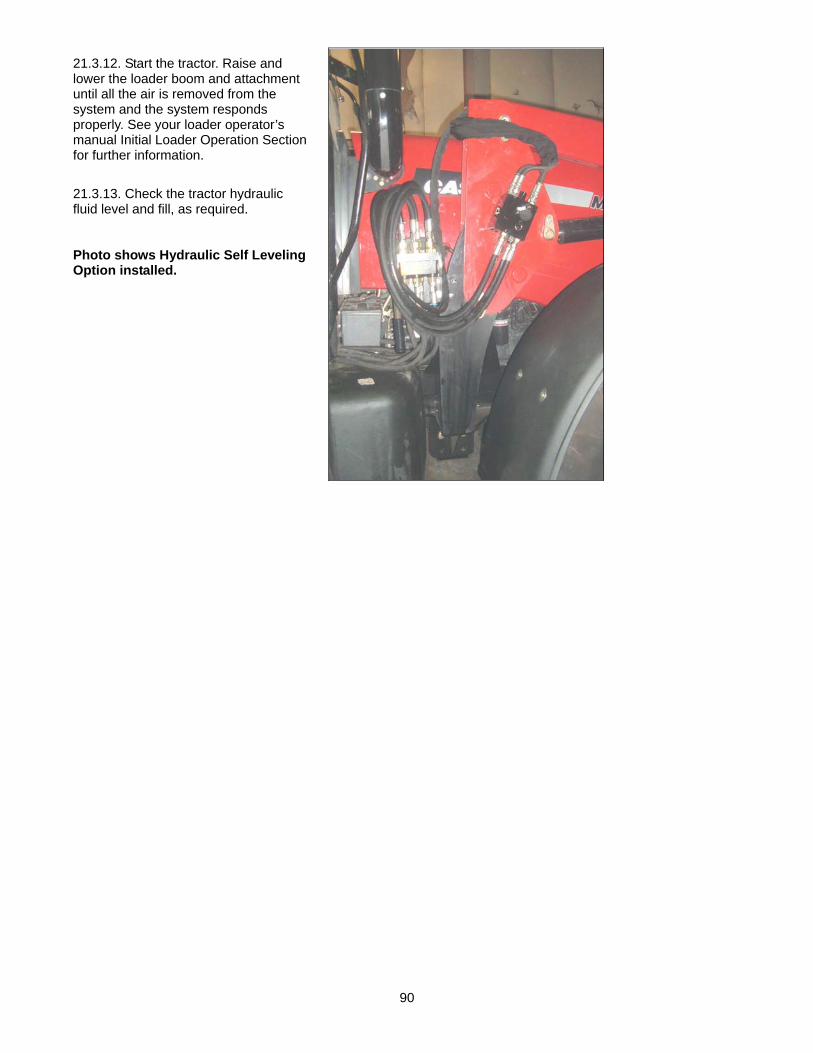
90
21.3.12. Start the tractor. Raise and lower the loader boom and attachment until all the air is removed from the system and the system responds properly. See your loader operator’s manual Initial Loader Operation Section for further information.
21.3.13. Check the tractor hydraulic fluid level and fill, as required. Photo shows Hydraulic Self Leveling Option installed.

91
21.4. SELF LEVEL VALVE COMPONENT FUNCTION (LOAD SENSE / CLOSED CENTER SYSTEMS) (STEEL BLOCK VERSION)
10 MODULATOR PLUG: 8 PO CHECK: This reduces the leakage from the bucket cylinders to the lift cylinder. 3 ANTI-CRANING RELIEF: Bypasses oil from the lift rod to tank when raising against fully extended bucket
cylinder. 4 ANTI-CAV RELIEF: Provides oil to the rod end of lift cylinders when the bucket is against the rollback
stops and the loader is lowered. 5 LOAD MODULATOR SENSE CHECK: Provides signal to modulator during lowering. 2 PLUG: 7 COUNTER BALANCE VALVE: Provides the bucket load holding, (rod end) when unit is loaded to assure
bucket does not roll forward.
CAUTION: NEVER disassemble this self-leveling valve unless you are a Factory trained mechanic. Failure to follow these instructions will void warranty and could cause the self leveling valve to operate incorrectly. If you need service on this valve return complete unit to your Dealer for service.
10
4
2
5 7
8
3
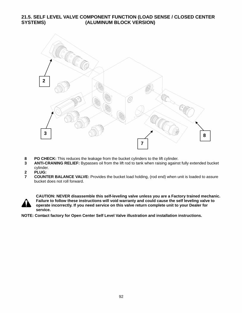
92
21.5. SELF LEVEL VALVE COMPONENT FUNCTION (LOAD SENSE / CLOSED CENTER SYSTEMS) (ALUMINUM BLOCK VERSION)
8 PO CHECK: This reduces the leakage from the bucket cylinders to the lift cylinder. 3 ANTI-CRANING RELIEF: Bypasses oil from the lift rod to tank when raising against fully extended bucket
cylinder. 2 PLUG: 7 COUNTER BALANCE VALVE: Provides the bucket load holding, (rod end) when unit is loaded to assure
bucket does not roll forward.
CAUTION: NEVER disassemble this self-leveling valve unless you are a Factory trained mechanic. Failure to follow these instructions will void warranty and could cause the self leveling valve to operate incorrectly. If you need service on this valve return complete unit to your Dealer for service.
NOTE: Contact factory for Open Center Self Level Valve illustration and installation instructions.
2
7 8 3
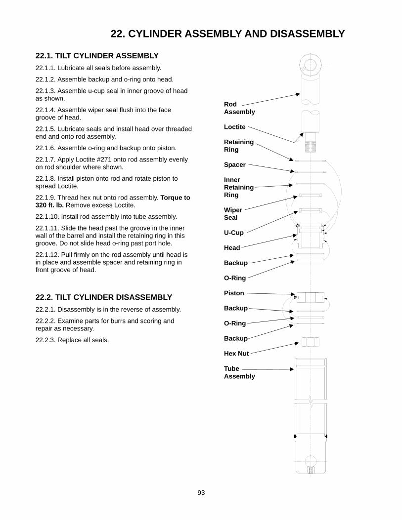
93
22. CYLINDER ASSEMBLY AND DISASSEMBLY
22.1. TILT CYLINDER ASSEMBLY 22.1.1. Lubricate all seals before assembly.
22.1.2. Assemble backup and o-ring onto head.
22.1.3. Assemble u-cup seal in inner groove of head as shown.
22.1.4. Assemble wiper seal flush into the face groove of head.
22.1.5. Lubricate seals and install head over threaded end and onto rod assembly.
22.1.6. Assemble o-ring and backup onto piston.
22.1.7. Apply Loctite #271 onto rod assembly evenly on rod shoulder where shown.
22.1.8. Install piston onto rod and rotate piston to spread Loctite.
22.1.9. Thread hex nut onto rod assembly. Torque to 320 ft. lb. Remove excess Loctite.
22.1.10. Install rod assembly into tube assembly.
22.1.11. Slide the head past the groove in the inner wall of the barrel and install the retaining ring in this groove. Do not slide head o-ring past port hole.
22.1.12. Pull firmly on the rod assembly until head is in place and assemble spacer and retaining ring in front groove of head.
22.2. TILT CYLINDER DISASSEMBLY 22.2.1. Disassembly is in the reverse of assembly.
22.2.2. Examine parts for burrs and scoring and repair as necessary.
22.2.3. Replace all seals.
Rod Assembly Loctite Retaining Ring Spacer Inner Retaining Ring Wiper Seal U-Cup Head Backup O-Ring Piston Backup O-Ring Backup Hex Nut Tube Assembly

94
22.3. LIFT CYLINDER ASSEMBLY 22.3.1. Lubricate all seals before assembly.
22.3.2. Assemble wiper seal into face groove of head cap.
22.3.3. Assemble backup and o-ring onto head.
22.3.4. Assemble u-cup seal in inner groove of head as shown.
22.3.5. Lubricate seals and install head over threaded end and onto rod assembly.
22.3.6. Assemble wear ring, yellow o-ring, and backup onto piston.
22.3.7. Apply Loctite #271 onto rod assembly evenly on rod shoulder where shown.
22.3.8. Install piston onto rod and rotate piston to spread Loctite.
22.3.9. Thread hex nut onto rod assembly. Torque to 320 ft. lb. Remove excess Loctite.
22.3.10. Install rod assembly into tube assembly.
22.3.11. Slide the head past the groove in the inner wall of the barrel. Secure head cap by tightening set screw (not shown) and nylon ball.
22.4. LIFT CYLINDER DISASSEMBLY 22.4.1. Disassembly is in the reverse of assembly.
22.4.2. Examine parts for burrs and scoring and repair as necessary.
22.4.3. Replace all seals.
Rod Assembly Loctite Wiper Seal Head Cap Nylon Ball U-Cup Head Backup O-Ring Backup O-Ring Piston Wear Ring Hex Nut Tube Assembly

95
23. LEAK DOWN INSPECTION
IMPORTANT NOTE: Following leakage test should only be done by a qualified mechanic.
23.1. FRONT END LOADER FIELD LEAK DOWN INSPECTION AND TEST
CAUTION: Do not stand, walk, or work under a raised loader tilt or attachment unless it is securely blocked and held in position.
CAUTION: Escaping hydraulic fluid under pressure can have sufficient force to penetrate the skin, causing serious personal injury. Do not use HANDS to search for suspected leaks. If injured by escaping fluid, obtain medical treatment immediately.
CAUTION: Visually check for hydraulic leaks and broken, missing, or malfunctioning parts. Never use your hand to check for suspected leaks under pressure. Use a piece of cardboard or wood for this purpose. Escaping hydraulic fluid or diesel fuel leaking under pressure can have sufficient force to penetrate the skin and cause serious infection or other personal injury. If injured by leaking fluid, seek medical attention immediately.
CAUTION: To prevent personal injury, relieve all pressure before disconnecting fluid lines.
CAUTION: Before applying hydraulic pressure, make sure all hydraulic connections are tight and components are in good condition.
CAUTION: Be sure to purge all the air from the hydraulic system before attempting to raise or lower this machine.
23.1.1. Make sure all fittings are tight and not leaking. Make sure that there is no external leakage from the valve, fittings or cylinders. If leakage exist repair before doing any of the following test.
23.1.2. Make sure that there is adequate hydraulic fluid in the reservoir.
23.1.3. Install pressure gauge in the circuit you are testing. If testing Lift cylinder leak down install pressure gauge in base and rod end circuit of lift cylinder between the loader valve and the lift cylinder. If testing the tilt cylinder leak down install pressure gauge in rod end circuit of the tilt cylinder between the loader valve and the cylinder.
23.1.4. Photo shows typical pressure gauge setup. Connect 5000 psi min. pressure gauge between loader valve and cylinder circuit you are checking.
23.1.5. Either quick couple or solid mount the pressure gauge in the circuit you are testing. Make sure there are no hydraulic line leaks in system before testing your loader
23.1.6. Cycle or operate the hydraulic system till the control valve is warm to the touch.

96
IMPORTANT: Always check leakage of lift cylinder seals before you test lift circuit loader valve spool leakage.
23.2. LEAKAGE TEST FOR LIFT CYLINDER SEALS (Open Center Systems) NOTE: Clean all parts thoroughly before disassembling any fittings. Cycle or operate the hydraulic system till the control valve is warm to the touch.
23.2.1. Install pressure gauges in the lift cylinder rod and base end circuit.
23.2.2. With no load in bucket raise loader to full height and then hold pressure on unit for a few seconds. Read Base end pressure it should equal tractor hydraulic system pressure. Leave unit raised for a 5 to 10 minutes and then read rod end pressure. Rod end pressure should read zero. If pressure starts to increase in rod end and or base end of cylinder. Lower loader and repair or replace damaged lift cylinder. If rod end pressure does not increase no cylinder repair is required. This test can also be done with some load in bucket and with the loader only raised slightly off of ground. This will increase the pressure in the cylinder and check the seals at a higher pressure. NOTE: Make sure that the pressure in the rod end circuit is zero or very low when starting this test. OPTIONAL WAY TO CHECK LIFT CYLINDER SEAL LEAKAGE ON OPEN CENTER SYSTEMS. (FOLLOW THESE INSTRUCTIONS IF CHECKING A CLOSED CENTER OR LOAD SENSE SYSTEM)
23.2.3. Remove lift cylinder rod end hose. Install tee fitting with a high pressure ball valve and drain hose assembled to the rod end of the lift cylinder circuit. Insert end of drain hose into a drain pan.
Tee Fitting.
High Pressure Ball Valve.
Drain Hose.
Lift Cylinder Rod End Hose.
Install pressure gauge in the base and rod end of Lift cylinder

97
High Pressure Ball Valve and fittings installed on a loader.
Lift Cylinder Rod End Hose.
Tee Fitting.
High Pressure Ball Valve.
Drain Hose.
23.2.4. Install a pressure gauge in the lift circuit base end.
23.2.5. With high pressure ball valve in off position, place a load in the bucket and raise loader to some height. The load in the bucket and the lift height should be such that it induces a target reference pressure of 1500 psi in the cylinders.
23.2.6. Disconnect rod end lift cylinder circuit from loader valve by disconnecting quick coupler. If quick coupler does not exist install one in line before proceeding with this test.
23.2.7. Slowly open high pressure ball valve directing drain hose to drain pan.
Note: If oil flows out of drain hose and loader lowers, cylinders will need to be repaired or replaced. Note: If no flow is seen, no repair of lift cylinder is required.
23.2.8. Reconnect rod end of lift cylinder circuit by reconnecting quick coupler.
23.2.9. Lower loader to ground. Relieve pressure and remove high pressure ball valve and tee fitting. Re-connect loader hose and fitting.
Base end Of lift cylinder.
Rod end of lift cylinder.

98
IMPORTANT: Always check leakage of lift cylinder seals before you test lift circuit loader valve spool leakage.
23.3. LEAKAGE TEST FOR LIFT CIRCUIT LOADER VALVE SPOOL NOTE: Clean all parts thoroughly before disassembling any fittings. Cycle or operate the hydraulic system till the control valve is warm to the touch.
23.3.1. Install a pressure gauge in the lift circuit base end.
23.3.2. Cycle the lift cylinders to full extend and then full retract a minimum of 5 times to expel any air in the system. The cylinders should be cycled with the engine near maximum rpm. The bucket should not be loaded during cycling.
23.3.3. Place a load in the bucket and raise to some height. The load in the bucket and the lift height should be such that it induces a target pressure of 1000 psi in the lift cylinder base end circuit.
23.3.4. Disconnect rod end lift cylinder circuit from loader valve by disconnecting quick coupler. If quick coupler does not exist install one in line before proceeding with this test.
23.3.5. Use a permanent marker and mark a line on the cylinder rod 3 inches away from the tube end of the cylinder. (See photo on following page)
23.3.6. After a 10 minute period of time measure the distance between the line and the end of the cylinder and subtract the distance from 3 inches to determine how much the cylinder has retracted.
23.3.7. Refer to Leak down Rate chart in these instructions for the acceptable leak down rate for your specific cylinder sizes. Step A: Mark cylinder rod with a permanent marker 3” from cylinder end.
Step B: Then measure the distance between end of cylinder and mark after a 10 minute period of time.
Rod End of Lift Cylinder
Initial Mark on Lift Cylinder Rod 3” from end of cylinder.
23.4. LEAKAGE TEST FOR TILT OR BUCKET CYLINDER, SEALS NOTE: Clean all parts thoroughly before disassembling any fittings. Cycle or operate the hydraulic system till the control valve is warm to the touch.
23.4.1. Install a pressure gauge in the tilt circuit rod end.
23.4.2. Cycle the tilt cylinders to full extend and then full retract a minimum of 5 times to expel any air in the system. The cylinders should be cycled with the engine near maximum rpm. The bucket should not be loaded during cycling. Use regen function of valve (If equipped) when expelling air from the tilt circuit.
23.4.3. Lower the loader to the ground, relieve hydraulic pressure and disconnect rod end tilt cylinder circuit from loader valve by disconnecting quick coupler. If quick coupler does not exist install one in line before proceeding with this test.

99
23.4.4. Place a load in the bucket and raise the boom slightly off the ground. The load should be such that it induces a target reference pressure between 1000 to 1500 psi in the cylinders refer to pressure gauge previously installed.
23.4.5. Place a mark using a permanent marker on the cylinder rod at the end of the cylinder.
NOTE: Never mark the cylinder until the weight has been applied to the loader and your pressure gauge reads 1000 to 1500 psi.
Measure from end of cylinder after 10 minutes.
Initial Mark on Tilt Cylinder Rod
23.4.6. After a 10 minute period of time measure the distance from the end of cylinder to the mark.
23.4.7. If this distance has increased then some internal leakage is present. If excessive leakage is found cylinder will need to be replaced or repaired.
23.4.8. Lower the loader and bucket to the ground, and re-connect the rod end hose.
23.5. TILT OR BUCKET CYLINDER VALVE SPOOL LEAKAGE NOTE: Clean all parts thoroughly before disassembling any fittings. Cycle or operate the hydraulic system till the control valve is warm to the touch.
23.5.1. Install a pressure gauge in the tilt circuit rod end
23.5.2. Cycle the tilt cylinders to full extend and then full retract a minimum of 5 times to expel any air in the system. The cylinders should be cycled with the engine near maximum rpm. The bucket should not be loaded during cycling. Use regen function of valve (if your loader is equipped with it) when expelling air from the tilt circuit.
23.5.3. With the bucket lip approximately level and on the ground, place a load in the bucket and raise the boom slightly off the ground. The load should be such that it induces a pressure of 1000 psi in the cylinder rod end. Refer to pressure gauge previously installed. Place a mark using permanent marker on the cylinder rod at the end of the cylinder after load has been applied. (Refer to previous page photo.) After a 10 minute period of time measure the distance from the cylinder end to the mark to determine how much the cylinder has extended. Then refer to Leak down Rate Chart in these instructions for the acceptable leak down rate for your specific cylinder sizes.
23.5.4. If valve leak down rate is found to be more than allowable rate contact factory before returning valve.
IMPORTANT: These tests must be done very accurately to make sure the results are accurate. Any valve that is returned and not found to exceed the manufacture's allowable leakage rate will not be covered under warranty.
IMPORTANT: Contamination in hydraulic system will cause damage to the loader valve which will increase valve spool leakage rates. If a returned valve is found to be damaged because of contamination it will not be covered under warranty. Keep your hydraulic system maintained at all times and make sure you clean all fittings and etc. when disconnecting or connecting hydraulic fittings.

100
23.6. ACCEPTABLE LIFT CYLINDER LEAK DOWN RATES IMPORTANT: Always double check your cylinder size to make sure it matches the information below.
23.6.1. Following are the allowable leak down rates specific to your loader lift cylinder sizes. If your loader is equipped with a load sense system acceptable leakage rates can be 30% higher than shown in this chart.
Lift Cylinder Bore Size
Lift Cylinder Outside Diameter
Leak Down Rate per 10 minutes
Loader Model Numbers
1-1/2" 1-7/8" 1.72” ML102 1-3/4" 2-1/8" 1.27” ML25, ML104, ML105, ML106,
ML108, ML108H 2” 2-3/8” .97” ML110, ML111, ML112, ML114
2-1/4” 2-5/8” .76” KL1470, KL1470S 2-1/2” 2-7/8” .62” ML230, ML260, KL1590, KL1590S 2-3/4” 3-1/8” .51” ML245, ML255
3” 3-3/8” .43” ML170, ML264, ML265, ML270, ML275, KL1730
3-1/4” 3-5/8” .37” 1660 3-1/2” 3-7/8” .32” 1750,1760, 1860
23.7. ACCEPTABLE TILT OR BUCKET CYLINDER LEAK DOWN RATES IMPORTANT: Always double check your cylinder size to make sure it matches the information below.
23.7.1. Following are the allowable leak down rates specific to your tilt cylinder sizes. If your loader is equipped with a load sense system leakage rate can be 30% higher than shown in this chart.
Tilt Cylinder Bore Size
Tilt Cylinder Outside Diameter
Tilt Cylinder Rod Diameter
Leak Down Rate per 10 minutes
Loader Model Numbers
1-1/2” 1-7/8” 1” 3.13” ML102 1-3/4” 2-1/8” 1” 1.9” ML25, ML104, ML105,
ML106, ML108, ML108H, ML110, ML111
2” 2-3/8” 1-1/4” 1.6” ML112, ML114, ML230, ML260, KL1470
2-1/4” 2-5/8” 1-1/4” 1.11” ML245, KL1470S, KL1590, KL1595
2-1/2” 2-7/8” 1-1/4” .83 ML264, KL1595S, KL1730 2-1/2” 2-7/8” 1-1/2” .97” ML170, ML255, ML265,
ML270, ML275 2-3/4” 3-1/8” 1-1/2” .73” 1660,1760
3” 3-3/8” 1-3/4” .65” 1750 3-1/4” 3-5/8” 1-3/4” .51” 1860

101
24. TROUBLE SHOOTING PROCEDURES This Trouble Shooting Chart is provided for reference to possible loader operational problems. Determine the problem that best describes the operational problem being experienced and eliminate the possible causes as listed by following the correction procedures. For further assistance contact your dealer.
24.1. TROUBLE SHOOTING FOR ALL LOADERS PROBLEM POSSIBLE CAUSE CORRECTION
Lift and Tilt Cylinders inoperative Low hydraulic fluid level. Check and replenish hydraulic fluid.
Hydraulic hoses connected improperly.
Check and correct hydraulic hose connections
Hydraulic Hoses to/from loader valve blocked.
Check for damaged (kinked) hoses, etc.
Loader valve or tractor main relief valve stuck open.
Check system pressure. Repair or replace relief valve.
Low system pressure supplied from hydraulic pump.
Check system pressure. Repair or replace pump.
Loader valve linkage broken. Inspect. Repair as required.
Quick disconnect coupler(s) are not fully connected.
Check coupler connections. Replace coupler(s) if necessary.
Hydraulic hose or tubeline blockage.
Check all hoses and tubes for leaks, damage, or restrictions. Replace damaged or restricted hoses or tube lines.
Cylinder piston assembly defective (not sealing).
Check cylinders for internal leakage as described in service section under cylinder leakage tests.
Loader valve blockage. Inspect for blockage. Disassemble valve if necessary.
Lift and/or tilt cylinders operate in wrong direction relative to valve handle position
Hydraulic hoses connected incorrectly.
Correct hydraulic hose connections.
Attachment will dump but will not rollback (Only if your loader valve is equipped with regen)
Hydraulic circuit connected incorrectly.
Refer to plumbing diagram and correct hose connections.
Slow or erratic lift Low hydraulic fluid level. Check and replenish hydraulic fluid.
Cold hydraulic fluid. Allow hydraulic system to warm up to operating temperature.
Engine R.P.M. too slow (hydraulic pump R.P.M. too slow).
Increase engine speed to obtain satisfactory loader operation.
Excessive weight in bucket. Material weight exceeds maximum specified loader capacity.
Reduce material load.
Loader valve linkage binding/defective.
Check loader valve linkage and repair if worn/defective.
Aeration of hydraulic fluid Refer to "Aeration of Hydraulic Fluid".

102
PROBLEM POSSIBLE CAUSE CORRECTION
Quick disconnect coupler restriction or coupler.
Check coupler connections. Repair or replace.
Hydraulic hose or tubeline restriction (hoses/tubeline kinked or pinched).
Check hoses and tubelines for evidence of restriction.
Lift cylinder piston assembly leakage.
Check cylinders for leakage. Repair as needed.
Relief valve erratic or set below specifications.
Check and reset relief valve setting as needed.
Loader valve leaking internally. (Bypassing fluid within valve.)
Replace loader valve and recheck operation.
Inadequate hydraulic pump capacity.
Refer to "Hydraulic Pump Capacity Inadequate".
Inadequate lifting capacity Engine R.P.M. too slow. Increase engine R.P.M.
Excessive load – material weight exceeds specified loader capacity.
Reduce Load.
Relief valve setting below specifications.
Check and reset relief valve setting as needed.
Lift cylinder piston assembly leakage.
Check cylinders for leakage. Repair as needed.
Loader valve leaking internally. Replace loader valve and recheck operation.
Hydraulic pump defective. Refer to "Hydraulic Pump Capacity Inadequate".
Aeration of Hydraulic Fluid (generally indicated by foamy appearance of fluid).
Low hydraulic fluid level. Check and refill hydraulic system to proper level.
Air leaking into suction side of hydraulic pump.
Check for loose or defective connections between reservoir and hydraulic pump.
Hydraulic fluid foaming due to improper hydraulic oil usage.
Refer to Tractor Operator’s Manual and replace hydraulic oil using recommended hydraulic oil.
System relief valve squeals. Cold Hydraulic Fluid. Allow hydraulic fluid to warm up to operating temperature.
Excessive load in bucket. Weight exceeds specified loader capacity.
Reduce load.
Relief valve setting below specifications.
Check and reset valve setting as needed.
Hydraulic hose, tubeline, or quick disconnect coupler restriction.
Check for evidence of restriction in hydraulic oil flow. Repair or replace defective components.
Loader drops with loader valve spool in "Centered" position (no external oil leakage evident.)
Cylinder Piston assembly leakage. Check cylinders for leakage.
Loader valve internal leakage. Replace loader valve and recheck.

103
PROBLEM POSSIBLE CAUSE CORRECTION
Note: A gradual drop over an extended period of time is a normal condition.
Run Leakage Test to see if hydraulic components meet specification.
Loader valve spool(s) will not return to centered position.
Valve handle linkage binding. Determine origin of binding and repair.
Loader valve spool centering is broken.
Replace centering spring.
Loader valve spool binding in valve body spool bore.
Disassemble valve for inspection and repair.
Loader bucket moves freely after dumping load
Tilt cylinder cavitation has occurred. Use of regen function (if equipped) while dumping load will eliminate problem.
Contact Factory for optional orifice sizes.
External hydraulic fluid leakage. Loose hydraulic connection. Tighten loose connections.
Defective hydraulic hose, tubeline, adapter fitting or adapter fitting o-ring.
Check for origin of oil leak and replace defective part.
Loader valve o-rings defective. Replace defective o-rings.
Loader valve spool or body damaged or worn.
Replace loader valve.
Cylinder rod packing set leakage. Check cylinders for leakage. Repair as needed.
Hydraulic pump capacity inadequate.
Cold hydraulic fluid. Allow hydraulic fluid to warm up to operating temperature.
Engine R.P.M. too slow. Increase engine R.P.M.
Low hydraulic fluid supply. Refer to Tractor Operator’s Manual for service recommendations.
Hydraulic hose restriction. Check for evidence of restriction in hydraulic hoses.
Hydraulic pump defective. Refer to Tractor Operator’s manual for recommended service procedures. Replace hydraulic pump if determined to be defective.
Lift cylinder rods bend when lift cylinders extended.
Excessive shock load on lift cylinders during transport.
Replace defective parts. Review and observe proper and safe operational practices.
Bucket cutting edge wear is uneven side to side
Bucket is not level to ground. Check rear tire inflation and adjust to level bucket to ground.
Bucket cutting edge wear rate is excessive. (Wear rate is even across full width of bucket).
Incorrect operational practices. Excessive down pressure placed on bucket when used on hard abrasive surfaces.
Refer to operation – scraping section for correct operating procedures. Utilize float position.
Bucket wear pads worn. Replace wear pads.
Note: Extensive use of bucket on concrete or asphalt surfaces will accelerate wear rate of bucket cutting edge.

104
PROBLEM POSSIBLE CAUSE CORRECTION
Loader is slow and/or will not dump.
Hydraulic oil too heavy. Change to proper oil.
Oil filter plugged. Clean or replace filter.
Hydraulic pump worn. Repair or replace pump.
Oil line restricted or leaking. Check all hoses and tubes for leaks, damage, or restrictions. Replace damaged or restricted hoses or tube lines.
Loader valve does not shift properly. Inspect clean, repair, or replace valve.
Cylinder leaks internally. Replace seals.
Faulty valve. Repair or replace valve.
Loader chatters or vibrates when raising or lowering.
Air in hydraulic system. Cycle lift cylinders and tilt cylinders.
Oil level too low. Add oil as required.
Slow leakdown. Worn loader valve. Have authorized KMW dealer replace valve.
Worn cylinder piston seals. Have authorized KMW dealer replace seals.
Attachment will dump but will not rollback
Hydraulic circuit connected incorrectly.
Check that loader valve is connected to tilt cylinder correctly if valve is equipped with regen funtion.
24.2. TROUBLE SHOOTING OPTIONAL LOADER VALVE If your loader/tractor combination is equipped with an optional KMW Cable Controlled Loader valve and unit reacts in the following manner.
PROBLEM POSSIBLE CAUSE CORRECTION
Nothing happens when handle switch is activated
Tractor switch is not on. Turn tractor switch on.
Power circuit is not connected. Connect to tractor power supply that is only activated when tractor switch is on.
Switch does not have 12 volts. Trace circuit and find cause.
Solenoid valve does not have 12 volts when switch is activated.
If not, check switch by jumping terminal wires on switch in handle. If 12 volts are at solenoid valve, replace switch
If you have 12 volts at solenoid valve but valve does not function
Spool is sticking. Push in on each side of valve spool to free up spool as shown in installation instructions included with your valve kit.
Contamination in hydraulic oil causes spool to stick. Replace oil and filter.
Solenoid valve section is damaged. Replace solenoid valve section.

105
24.3. TROUBLE SHOOTING OPTIONAL COMFORT DRIVE PROBLEM POSSIBLE CAUSE CORRECTION
Comfort drive does not activate. Turn on comfort drive and check to see if 12 volts are at solenoid.
If 12 volts are not available, inspect and repair as follows.
Solenoid not properly grounded If not properly grounded, repair.
Fuse replace if required
Wire damaged or cut. If damaged repair or replace
Switch does not have 12 volts. Trace circuit and find cause.
Tractor switch is not on. Turn tractor switch on.
Power circuit not connected. Connect to tractor power supply that is only activated when tractor switch is on.
Comfort drive does not work properly
Pre-charge pressure is not correct Check pre-charge pressure of each end of accumulator and correct as required.
Leak in fluid or gas side of accumulator
Repair and replace accumulator seals
Circuits not connected correctly Trace circuits and make sure large end of accumulator is connected to base end of lift cylinder.
24.4. TROUBLE SHOOTING OPTIONAL SELF LEVELING PROBLEM POSSIBLE CAUSE CORRECTION
Flow divider spool stuck. *Check flow divider spool for free operation. (Check for contamination.)
Bucket does not maintain level while raising at high idle.
Raise counterbalance valve stuck. *Remove and check for contamination.
Flow divider spool stuck. *Check flow divider cartridge for free operation.
(Open Center system only) Load drop modulator valve stuck.
*Remove and check for contamination. (Spool should move freely in bore.)
Bucket does not maintain level while lowering at high idle.
Reduce load being handled. Bucket/Attachment rolls forward while handling heavy load.
Counterbalance Valve open.
Rollback load before operating loader.
Bad bucket cylinder seal. Repack cylinder.
Raise counterbalance valve stuck. *Remove and check for contamination.
Anti-Cavitation relief malfunction. *Check Anti-Cavitation valve cartridge. Remove and check for contamination or replace. Contact factory for adjustment information.
Excessive bucket drift in the dump direction.
Excessive loader control valve bucket spool port leakage.
Check with Factory on acceptable valve spool leakage rate. Replace if required.

106
PROBLEM POSSIBLE CAUSE CORRECTION
Bucket moves freely when putting down pressure on cutting edge.
Pilot operated check is not closing (cartridge plus pilot piston).
*Remove and check for contamination. Replace if required.
Too large of load. Reduce load. Bucket does not level down while lowering. Starting with load rolled forward. Rollback attachment slightly before
lowering loader.
Loader bounces with lowering load.
Low hydraulic flow. Increase tractor RPM to increase hydraulic flow.
Bucket does not maintain Level while raising
Bucket self leveling is designed to work optimally at high RPM.
Run engine at med. To high RPM.
Bucket does not maintain Level while lowering on Open Center system.
Loader valve lift spool not fully stroked.
Fully stroke the valve spool.
Bucket does not maintain Level while lowering on Load Sense and Closed Center systems.
Loader valve lift spool is fully stroked.
Feather the loader lift spool.
Self leveling function is delayed after lowering loader.
Loader being lowered with attachment against the rollback stops.
Lowering loader with bucket rolled slightly forward will reduce delay.
Self-Leveling does not operate after initial hook-up.
Circuit not hooked up correctly. Check that circuits are hooked up as follows.
Float position of loader does not operate.
Check if installed on Open Center Valve.
If installed on Open Center System float will not operate.
Self Level Valve Ports
to Loader Valve Self Level Valve Ports to Loader Cylinders
Circuit Color Tag
1 5 Lift Base Green 2 6 Lift Rod Blue 3 7 Tilt Base Yellow 4 8 Tilt Rod Red
*NOTE: This service must only be accomplished by an Authorized KMW Service Person. Failure to follow these instructions will void warranty.

107
25. TORQUE CHART

108
26. NOTES

109
27. PARTS MANUAL
Illustrations All parts are illustrated in "exploded views" which show the individual parts in their normal relationship to each other. Reference numbers are used in the illustrations. These numbers correspond to those in the "Reference Number" column and are followed by the quantity required and description.
Directional Reference Right hand (RH) and left hand (LH) sides are determined by standing at the rear of the unit and facing in the direction of forward travel.
Parts Order Orders must give the complete description, correct part number, the total amount required, the product model, all the necessary serial numbers, the method of shipment and the shipping address.
Parts Breakdown Contact your local KMW dealer for service parts break down.

110
28. DECALS & MANUALS
3 2 4
6
1 5
7

111
DECALS & MANUALS Reference Description Part No. Qty.
1 ..............................Decal – Warning.......................................................................0595-3084 ................................1 2 ..............................Decal – Warning.......................................................................0595-3001 ................................1 3 ..............................Decal – Danger ........................................................................0595-3002 ................................1 4 ..............................Decal – Warning.......................................................................0595-3003 ................................1 5 ..............................Decal – Warning.......................................................................0595-3004 ................................1 6 ..............................Decal – KMW ..........................................................................0595-3088 ................................2 ................................Decal – KMW ..........................................................................0595-3093 ................................1 7 ..............................Decal – 1860 ............................................................................0595-3098 ................................2 8 ..............................Decal – Important.....................................................................0595-3087 ................................2 10............................Manual, Operator & Parts ........................................................2503-1042 ................................1 11 ............................Decal – Caution........................................................................0595-3086 ................................2 14............................Decal – Solenoid Third Function..............................................0595-2263 ................................1
11
8
14
10

112
DECALS & MANUALS Reference Description Part No. Qty.
21............................Decal – Caution........................................................................0595-2190 ................................1 22............................Decal – Caution........................................................................0595-3054 ................................1 23............................Decal – Danger ........................................................................0595-3050 ................................1 24............................Decal – Warning.......................................................................0595-3051 ................................1 25............................Decal – Warning.......................................................................0595-3052 ................................1 26............................Decal – Caution........................................................................0595-3053 ................................1 28............................Decal – Warning – Accumulator...............................................0595-3085 ................................1
25
22
23
24
21
26
28

113
29. BOOM ASSEMBLY
Loader Decal Locations
WARNING
WARNING
WARNING WARNING
CAUTION
0595-3004
0595-3001 0595-3002
0595-3003 0595-3084
CAUTION0595-3086
11
1
25
14
24 20
19
13
16
35
32
34
36
33
31
2
12
15

114
BOOM ASSEMBLY Reference Description Part No. Qty.
1 ..............................Bearing Box Assembly LH .......................................................1002-3114 ................................1 2 ..............................Bearing Box Assembly RH.......................................................1002-3115 ................................1 3 ..............................Boom Assembly KMW 1860 ....................................................1100-3039 ................................1 4 ..............................Bucket Linkage Assembly RH..................................................1108-3064 ................................1 5 ..............................Outside Boom Link Assembly RH ............................................1108-3062 ................................1 6 ..............................Outside Boom Link Assembly LH.............................................1108-3061 ................................1 7 ..............................Inside Boom Link Assembly RH...............................................1108-3060 ................................1 8 ..............................Parking Leg ..............................................................................1104-3049 ................................2 9 ..............................Pivot Pin 1.25" x 7.93"..............................................................0550-5023 ................................4 10............................Pivot Pin 1.25" x 4.91"..............................................................0550-5021 ................................2 11 ............................Pivot Pin 1.375" x 4.91"............................................................0550-5022 ................................2 12............................Pivot Pin 1.375" x 5.98"............................................................0550-5024 ................................2 13............................Pivot Pin 1.375" x 5.98"............................................................0550-5037 ................................2 14............................Plated Pin Assembly 1.25" x 7.25"...........................................0551-3058 ................................2 15............................Handle Lynch Pin .3125" x 2.25"..............................................0553-4419 ................................2 16............................Carriage Bolt 3/8"-16NC x 1-1/2" Gr5 ......................................0546-1118.................................8 17............................Clevis Pin 5/8" x 4"...................................................................0551-1256 ................................2 18............................Hitch Pin Clip .148" x 2-3/4".....................................................0553-4415 ................................4 19............................Flatwasher 3/8" Gr8 .................................................................0540-2007 ................................8 20............................Hex Nut 3/8"-16NC Stover Lock ..............................................0546-1119.................................8 21............................Hex Bolt 7/16"-14NC x 2-1/2" Gr5 ...........................................0548-2083 ................................4 23............................Hex Nut 7/16"-14NC Stover Lock ............................................0546-1151 ................................4 24............................Grease Fitting Straight 1/4"-28.................................................0530-1038 ..............................20 25............................Bushing Replaceable ...............................................................0310-2008 ................................4 26............................Inside Boom Link Assembly LH ...............................................1108-3059 ................................1 27............................Bucket Linkage Assembly LH ..................................................1108-3063 ................................1 28............................Bushing Replaceable ...............................................................0310-2007 ................................4 31............................Decal Warning..........................................................................0595-3001 ................................1 32............................Decal Danger ...........................................................................0595-3002 ................................1 33............................Decal Warning..........................................................................0595-3003 ................................1 34............................Decal Warning..........................................................................0595-3004 ................................1 35............................Decal Warning..........................................................................0595-3084 ................................1 36............................Decal Warning..........................................................................0595-3086 ................................2 37............................Decal Warning..........................................................................0595-2190 ................................2

115
BOOM ASSEMBLY
16
3 20
19
10
4
21
22
23
27
5
6
9
28
18
17
8
24
26 7
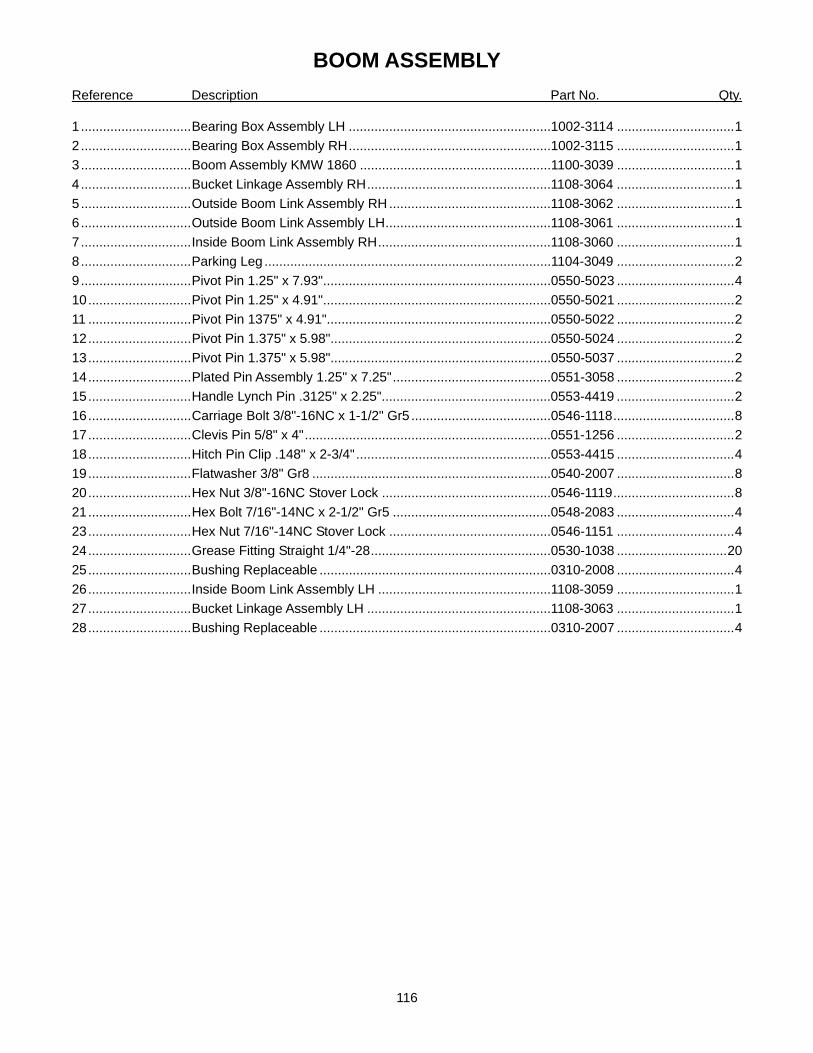
116
BOOM ASSEMBLY Reference Description Part No. Qty.
1 ..............................Bearing Box Assembly LH .......................................................1002-3114 ................................1 2 ..............................Bearing Box Assembly RH.......................................................1002-3115 ................................1 3 ..............................Boom Assembly KMW 1860 ....................................................1100-3039 ................................1 4 ..............................Bucket Linkage Assembly RH..................................................1108-3064 ................................1 5 ..............................Outside Boom Link Assembly RH ............................................1108-3062 ................................1 6 ..............................Outside Boom Link Assembly LH.............................................1108-3061 ................................1 7 ..............................Inside Boom Link Assembly RH...............................................1108-3060 ................................1 8 ..............................Parking Leg ..............................................................................1104-3049 ................................2 9 ..............................Pivot Pin 1.25" x 7.93"..............................................................0550-5023 ................................4 10............................Pivot Pin 1.25" x 4.91"..............................................................0550-5021 ................................2 11 ............................Pivot Pin 1375" x 4.91".............................................................0550-5022 ................................2 12............................Pivot Pin 1.375" x 5.98"............................................................0550-5024 ................................2 13............................Pivot Pin 1.375" x 5.98"............................................................0550-5037 ................................2 14............................Plated Pin Assembly 1.25" x 7.25"...........................................0551-3058 ................................2 15............................Handle Lynch Pin .3125" x 2.25"..............................................0553-4419 ................................2 16............................Carriage Bolt 3/8"-16NC x 1-1/2" Gr5 ......................................0546-1118.................................8 17............................Clevis Pin 5/8" x 4"...................................................................0551-1256 ................................2 18............................Hitch Pin Clip .148" x 2-3/4".....................................................0553-4415 ................................4 19............................Flatwasher 3/8" Gr8 .................................................................0540-2007 ................................8 20............................Hex Nut 3/8"-16NC Stover Lock ..............................................0546-1119.................................8 21............................Hex Bolt 7/16"-14NC x 2-1/2" Gr5 ...........................................0548-2083 ................................4 23............................Hex Nut 7/16"-14NC Stover Lock ............................................0546-1151 ................................4 24............................Grease Fitting Straight 1/4"-28.................................................0530-1038 ..............................20 25............................Bushing Replaceable ...............................................................0310-2008 ................................4 26............................Inside Boom Link Assembly LH ...............................................1108-3059 ................................1 27............................Bucket Linkage Assembly LH ..................................................1108-3063 ................................1 28............................Bushing Replaceable ...............................................................0310-2007 ................................4

117
30. HYDRAULIC CYLINDERS, HOSES, AND TUBELINES
1
2
3
4
5
6 8 7
9 10
11
12
13
14
15
16
17
17
17
17
18
20
20
21 22
22
23
24
24
24
24
25
26
27
27
27
28
29
30
31
32
33
34
35
36
36
37 38
39
40 41
19
42 43
44

118
HYDRAULIC CYLINDERS, HOSES, AND TUBELINES Reference Description Part No. Qty.
1 ..............................Hose Sock ...............................................................................0554-2064 ................................2 2 ..............................Hose 3/8" x 146" ......................................................................0582-2508848146 ....................2 3 ..............................Hose 3/8" x 147" ......................................................................0582-2508848147 ....................2 4 ..............................Fitting Tee.................................................................................0586-4828-828.........................4 5 ..............................Tie Strap Blue .14" x 5.5" .........................................................0554-2001 ................................2 6 ..............................Tie Strap Green .14" x 5.5" ......................................................0554-2004 ................................2 7 ..............................Tie Strap Yellow .14" x 5.5" ......................................................0554-2003 ................................2 8 ..............................Tie Strap Red .14" x 5.5"..........................................................0554-2002 ................................2 9 ..............................Hydraulic Hose 3/8" x 93" .......................................................0582-2508888093 ....................1 10............................Hydraulic Hose 3/8" x 60" ........................................................0582-2508888060 ....................1 11 ............................Hydraulic Hose 3/8" x 55" ........................................................0582-2508508055 ....................1 12............................Hydraulic Hose 3/8" x 88" ........................................................0582-2508508088 ....................1 13............................Hydraulic Hose 3/8" x 18" ........................................................0582-2508108018 ....................1 14............................Hydraulic Hose 3/8" x 22" ........................................................0582-2508108022 ....................1 15............................Hydraulic Hose 3/8" x 24" ........................................................0582-2508888024 ....................1 16............................Hydraulic Hose 3/8" x 17" ........................................................0582-2508888017 ....................1 17............................Tie Strap Black 5/16" x 14".......................................................0554-1013 ................................4 18............................Hose Cover ..............................................................................1212-2016 ................................1 19............................Cylinder, Lift LH........................................................................3160-2070 ................................1 20............................Cylinder, Tilt..............................................................................3150-2102 ................................2 21............................Hose Clamp Half ......................................................................1103-3016 ................................4 22............................Hex Head Cap Screw 5/16"-18 x 1-3/4"...................................0545-2029 ................................3 23............................Hex Head Lock Nut 5/16"-18 ...................................................0555-2133 ................................2 24............................Lockwasher 5/16".....................................................................0544-2009 ................................7 25............................Flatwasher 5/16" ......................................................................0543-2006 ................................2 26............................Sponge Rubber 6.75”"..............................................................0554-2010 ................................2 27............................Fitting ¾” ORBM x ¾” JICM.....................................................0586-1108-408 .......................12 28............................Hose Clamp Doubler................................................................1103-3017 ................................2 29............................Fitting Tee.................................................................................0586-3025 ................................2 30............................O-ring Face Seal Cap ..............................................................0586-3023 ................................2 31............................Hydraulic Hose 3/8” x 41” ........................................................0582-2808888041 ....................2 32............................Hydraulic Hose 3/8” x 45” ........................................................0582-2508888045 ....................2 33............................Relief Block w/ 5200 PSI Relief Cartridge................................0580-6221 ................................1 34............................Relief Block w/ 4200 PSI Relief Cartridge................................0580-6220 ................................1 35............................Relief Plate...............................................................................1204-3106 ................................1 36............................Hex Head Cap Screw 5/16”-18 x 2.5” ......................................0545-2032 ................................4 37............................Cylinder, Lift RH .......................................................................3160-2074 ................................1 38............................Hose Clamp .............................................................................1103-3024 ................................1 39............................Stover Hex Locknut 5/16”-18 ...................................................0546-1121 ................................2 40............................O-Ring ¾”.................................................................................0520-3002 ................................2 41............................Bulkhead Adapter ....................................................................0586-3026 ................................2 42............................Orifice Adapter Fitting .............................................................0586-3007 ................................1 43............................Orifice Plate, .098” ID ..............................................................0580-6282 ................................1 44............................Hydraulic Adapter ....................................................................0586-1108-508 .........................1

119
31. LIFT CYLINDER, LH Reference Description Part No. Qty.
0 ..............................Lift Cylinder (complete) ............................................................3160-2070 ................................1 1 ..............................Tube Assembly.........................................................................0100-2122 ................................1 2 ..............................Nut............................................................................................0530-2015 ................................1 3 ..............................Piston .......................................................................................0405-2021 ................................1 4 ..............................Seal Kit .....................................................................................0590-2078 ................................1 5 ..............................Head.........................................................................................0330-2044 ................................1 6 ..............................Head Cap .................................................................................0325-2003 ................................1 7 ..............................Rod Assembly ..........................................................................0200-2113 ................................1 ................................Grease Fitting Straight .............................................................0530-1038 ................................2 ................................Replaceable steel bushings (rod end not shown)....................0310-2002 ................................2
1 2 3 4 5 4 4 6 7 4

120
32. LIFT CYLINDER, RH Reference Description Part No. Qty.
0 ..............................Lift Cylinder (complete) ............................................................3160-2074 ................................1 1 ..............................Tube Assembly.........................................................................0100-2123 ................................1 2 ..............................Nut............................................................................................0530-2015 ................................1 3 ..............................Piston .......................................................................................0405-2021 ................................1 4 ..............................Seal Kit .....................................................................................0590-2078 ................................1 5 ..............................Head.........................................................................................0330-2044 ................................1 6 ..............................Head Cap .................................................................................0325-2003 ................................1 7 ..............................Rod Assembly ..........................................................................0200-2113 ................................1 ................................Grease Fitting Straight .............................................................0530-1038 ................................2 ................................Replaceable steel bushings (rod end not shown)....................0310-2002 ................................2
1 2 3 4 5 4 4 6 7 4

121
33. TILT CYLINDER Reference Description Part No. Qty.
0 ..............................Tilt Cylinder (complete) ............................................................3150-2102 ................................1 1 ..............................Tube Assembly.........................................................................0100-2121 ................................1 2 ..............................Nut............................................................................................0530-2015 ................................1 3 ..............................Piston .......................................................................................0405-2038 ................................1 4 ..............................Seal Kit .....................................................................................0590-2077 ................................1 5 ..............................Head.........................................................................................0330-2043 ................................1 6 ..............................Retaining Ring..........................................................................0560-2015 ................................1 7 ..............................Spacer ......................................................................................0541-2010 ................................1 8 ..............................Retaining Ring..........................................................................0560-2016 ................................1 9 ..............................Rod Assembly ..........................................................................0200-2112 ................................1 ................................Grease Fitting Straight .............................................................0530-1038 ................................2
1 2 3 4 5 4 4
6
9
8 7

122
34. ACCUMULATOR Reference Description Part No. Qty.
0 ..............................Accumulator (complete) ...........................................................0805-2001 ................................1 1 ..............................Rod Cap ...................................................................................0584-2007 ................................2 2 ..............................Charging Valve.........................................................................0526-2005 ................................2 3 ..............................End Cap ...................................................................................0330-2027 ................................2 4 ..............................Nylon Plug................................................................................0526-2004 ................................2 5 ..............................Backup .....................................................................................0525-2010 ................................2 6 ..............................O-Ring......................................................................................0520-2009 ................................2 7 ..............................T-Seal & Back-ups ...................................................................0525-2009 ................................2 8 ..............................Piston .......................................................................................0405-2020 ................................2 9 ..............................Wear Rings ..............................................................................0508-2000 ................................4 Note: Both Sides of Accumulator Use Same Component Parts
5 6 4 7 8 9 1 2
3

123
35. MID MOUNT COUPLER KIT
5
1
7
10
2
7
8
6
9
5
18
16
4
19
1
3
15
11
20
21
16
14
15
13
20
23 22 24
12
14 13
16 15
18 19
17

124
MID MOUNT COUPLER KIT Reference Description Part No. Qty.
1 ..............................Quick Coupler Mount ...............................................................1215-1000 ................................1 2 ..............................Quick Coupler, Female ............................................................0580-6082 ................................6 3 ..............................Quick Coupler, Male.................................................................0580-6081 ................................6 4 ..............................Fitting .......................................................................................0586-1108-408 .........................6 5 ..............................Bulkhead with Nut ....................................................................0586-3008 ................................6 6 ..............................O-Ring......................................................................................0520-3002 ................................6 7 ..............................Rubber Coupler Plug................................................................0584-2003 ................................6 8 ..............................Hex Head 1/2"-13NC x 1.25" Gr5 ............................................0545-2105 ................................2 9 ..............................Hex Nut 1/2"-13NC Lock..........................................................0555-2136 ................................2 10............................Flatwasher 1/2" Hardened .......................................................0540-2003 ................................1 11 ............................Hydraulic Hose.........................................................................0582-3108408170 ....................2 12............................Hydraulic Hose.........................................................................0582-3408508054 ....................4 13............................Tie Strap Green .14" x 5.5" ......................................................0554-2004 ................................2 14............................Tie Strap Blue .14" x 5.5" .........................................................0554-2001 ................................2 15............................Tie Strap Red .14" x 5.5"..........................................................0554-2002 ................................2 16............................Tie Strap Yellow .14" x 5.5" ......................................................0554-2003 ................................2 17............................Hydraulic Hose.........................................................................0582-2508508177 ....................2 18............................Tie Strap Black .14" x 5.5"........................................................0554-2008 ................................2 19............................Tie Strap White .14" x 5.5" .......................................................0554-2028 ................................2 20............................Tie Strap Black 5/16" x 14".......................................................0554-1013 ................................2 21............................Hose Sock................................................................................0554-2026 ................................1 22............................Orifice Plate .128" ....................................................................0580-6129 ................................1 23............................Fitting Adapter ..........................................................................0586-3007 ................................1 24............................Fitting .......................................................................................0586-1108-508 .........................1

125
36. LOADER VALVE 2 SPOOL (Load Sense)

126
LOADER VALVE 2 SPOOL (Load Sense) Reference Description Part No. Qty.
0 ..............................Valve Spool 2 Spool (load sense) ............................................0580-6175 ................................1 1 ..............................Section 1 Kit .............................................................................0580-6197 ................................1 1-01......................... Housing..............................................................................NSS ..........................................1 1-02......................... O-Ring 2.62 x 11.91 90 drom ............................................0580-6181 ................................1 1-03......................... O-Ring 2.62 x 17.86 70 drom ............................................0580-6181 ................................2 1-04......................... O-Ring 2.62 x 17.86 90 drom ............................................0580-6181 ................................2 1-05......................... O-Ring 2.62 x 28.24 90 drom ............................................0580-6181 ................................1 1-06......................... Spool..................................................................................NSS ..........................................1 1-07......................... Load Check .......................................................................0580-6182 ................................1 1-08......................... Float Detent Kit ..................................................................0580-6183 ................................1 1-10......................... End Cap.............................................................................0580-6184 ................................1 1-11 ......................... Cap Screw M6 x 90 Internal Socket Head ........................0580-6185 ................................2 1-SK* ...................... Seal Kit Section .................................................................0580-6181 ................................1 2 ..............................Section 2 Kit .............................................................................0580-6198 ................................1 2-01......................... Housing..............................................................................NSS ..........................................1 2-02......................... O-Ring 2.62 x 11.91 90 drom ............................................0580-6181 ................................1 2-03......................... O-Ring 2.62 x 17.86 70 drom ............................................0580-6181 ................................2 2-04......................... O-Ring 2.62 x 17.86 90 drom ............................................0580-6181 ................................2 2-05......................... O-Ring 2.62 x 28.24 90 drom ............................................0580-6181 ................................1 2-06......................... Spool..................................................................................NSS ..........................................1 2-07......................... Load Check .......................................................................0580-6182 ................................1 2-09......................... Spring Center Kit ...............................................................0580-6186 ................................1 2-10......................... End Cap.............................................................................0580-6184 ................................1 2-12......................... Cap Screw M6 x 40 Internal Socket Head ........................0580-6187 ................................2 2-SK* ...................... Seal Kit Section .................................................................0580-6181 ................................1 4 ..............................Section Inlet Kit ........................................................................0580-6200 ................................1 4-01......................... Housing..............................................................................NSS ..........................................1 4-14......................... Plug 7/8"-14 Internal Socket Head ....................................0580-6189 ................................1 4-15......................... Plug....................................................................................0580-6190 ................................2 4-16......................... Cap Screw M8 x 30 Internal Socket Head ........................0580-6191 ................................2 4-17......................... Mounting Bracket...............................................................0580-6192 ................................1 4-18......................... Hex Nut M8........................................................................0580-6193 ................................2 4-19......................... Plug BSPP 1/4" Internal Socket Head...............................0580-6194 ................................1 5 ..............................Section Outlet Kit .....................................................................0580-6201 ................................1 5-01......................... Housing..............................................................................NSS ..........................................1 5-02......................... O-Ring 2.62 x 11.91 90 drom ............................................0580-6181 ................................1 5-04......................... O-Ring 2.62 x 17.86 90 drom ............................................0580-6181 ................................2 5-05......................... O-Ring 2.62 x 28.24 90 drom ............................................0580-6181 ................................1 5-15......................... Plug Power Beyond...........................................................0580-6190 ................................2 5-16......................... Cap Screw M8 x 30 Internal Socket Head ........................0580-6191 ................................2 5-17......................... Mounting Bracket...............................................................0580-6192 ................................1 5-18......................... Hex Nut M8........................................................................0580-6193 ................................2 5-SK* ...................... Seal Kit Section .................................................................0580-6181 ................................1 6 ..............................Tie Rod Kit, 2 Spool .................................................................0580-6196 ................................1

127
37. LOADER VALVE 3 SPOOL (Load Sense)

128
LOADER VALVE 3 SPOOL (Load Sense) Reference Description Part No. Qty.
0 ..............................Valve Spool 3 Spool (Load Sense)...........................................0580-6170 ................................1 1 ..............................Section 1 Kit .............................................................................0580-6197 ................................1 1-01......................... Housing..............................................................................NSS ..........................................1 1-02......................... O-Ring 2.62 x 11.91 90 drom ............................................0580-6181 ................................1 1-03......................... O-Ring 2.62 x 17.86 70 drom ............................................0580-6181 ................................2 1-04......................... O-Ring 2.62 x 17.86 90 drom ............................................0580-6181 ................................2 1-05......................... O-Ring 2.62 x 28.24 90 drom ............................................0580-6181 ................................1 1-06......................... Spool..................................................................................NSS ..........................................1 1-07......................... Load Check .......................................................................0580-6182 ................................1 1-08......................... Float Detent Kit ..................................................................0580-6183 ................................1 1-10......................... End Cap.............................................................................0580-6184 ................................1 1-11 ......................... Cap Screw M6 x 90 Internal Socket Head ........................0580-6185 ................................2 1-SK* ...................... Seal Kit Section .................................................................0580-6181 ................................1 2 ..............................Section 2 Kit .............................................................................0580-6198 ................................1 2-01......................... Housing..............................................................................NSS ..........................................1 2-02......................... O-Ring 2.62 x 11.91 90 drom ............................................0580-6181 ................................1 2-03......................... O-Ring 2.62 x 17.86 70 drom ............................................0580-6181 ................................2 2-04......................... O-Ring 2.62 x 17.86 90 drom ............................................0580-6181 ................................2 2-05......................... O-Ring 2.62 x 28.24 90 drom ............................................0580-6181 ................................1 2-06......................... Spool..................................................................................NSS ..........................................1 2-07......................... Load Check .......................................................................0580-6182 ................................1 2-09......................... Spring Center Kit ...............................................................0580-6186 ................................1 2-10......................... End Cap.............................................................................0580-6184 ................................1 2-12......................... Cap Screw M6 x 40 Internal Socket Head ........................0580-6187 ................................2 2-SK* ...................... Seal Kit Section .................................................................0580-6181 ................................1 3 ..............................Section 3 Kit .............................................................................0580-6199 ................................1 3-01......................... Housing..............................................................................NSS ..........................................1 3-02......................... O-Ring 2.62 x 11.91 90 drom ............................................0580-6181 ................................1 3-04......................... O-Ring 2.62 x 17.86 90 drom ............................................0580-6181 ................................2 3-05......................... O-Ring 2.62 x 28.24 90 drom ............................................0580-6181 ................................1 3-06......................... Spool..................................................................................NSS ..........................................1 3-07......................... Load Check .......................................................................0580-6182 ................................1 3-13......................... Solenoid, electric direct acting...........................................0580-6188 ................................2 3-SK* ...................... Seal Kit Section .................................................................0580-6181 ................................1 4 ..............................Section Inlet Kit ........................................................................0580-6200 ................................1 4-01......................... Housing..............................................................................NSS ..........................................1 4-14......................... Plug 7/8"-14 Internal Socket Head ....................................0580-6189 ................................1 4-15......................... Plug....................................................................................0580-6190 ................................2 4-16......................... Cap Screw M8 x 30 Internal Socket Head ........................0580-6191 ................................2 4-17......................... Mounting Bracket...............................................................0580-6192 ................................1 4-18......................... Hex Nut M8........................................................................0580-6193 ................................2 4-19......................... Plug BSPP 1/4" Internal Socket Head...............................0580-6194 ................................1 5 ..............................Section Outlet Kit .....................................................................0580-6201 ................................1 5-01......................... Housing..............................................................................NSS ..........................................1 5-02......................... O-Ring 2.62 x 11.91 90 drom ............................................0580-6181 ................................1 5-04......................... O-Ring 2.62 x 17.86 90 drom ............................................0580-6181 ................................2 5-05......................... O-Ring 2.62 x 28.24 90 drom ............................................0580-6181 ................................1 5-15......................... Plug Power Beyond...........................................................0580-6190 ................................2 5-16......................... Cap Screw M8 x 30 Internal Socket Head ........................0580-6191 ................................2 5-17......................... Mounting Bracket...............................................................0580-6192 ................................1 5-18......................... Hex Nut M8........................................................................0580-6193 ................................2 5-SK* ...................... Seal Kit Section .................................................................0580-6181 ................................1 6 ..............................Tie Rod Kit, 3 Spool .................................................................0580-6195 ................................1
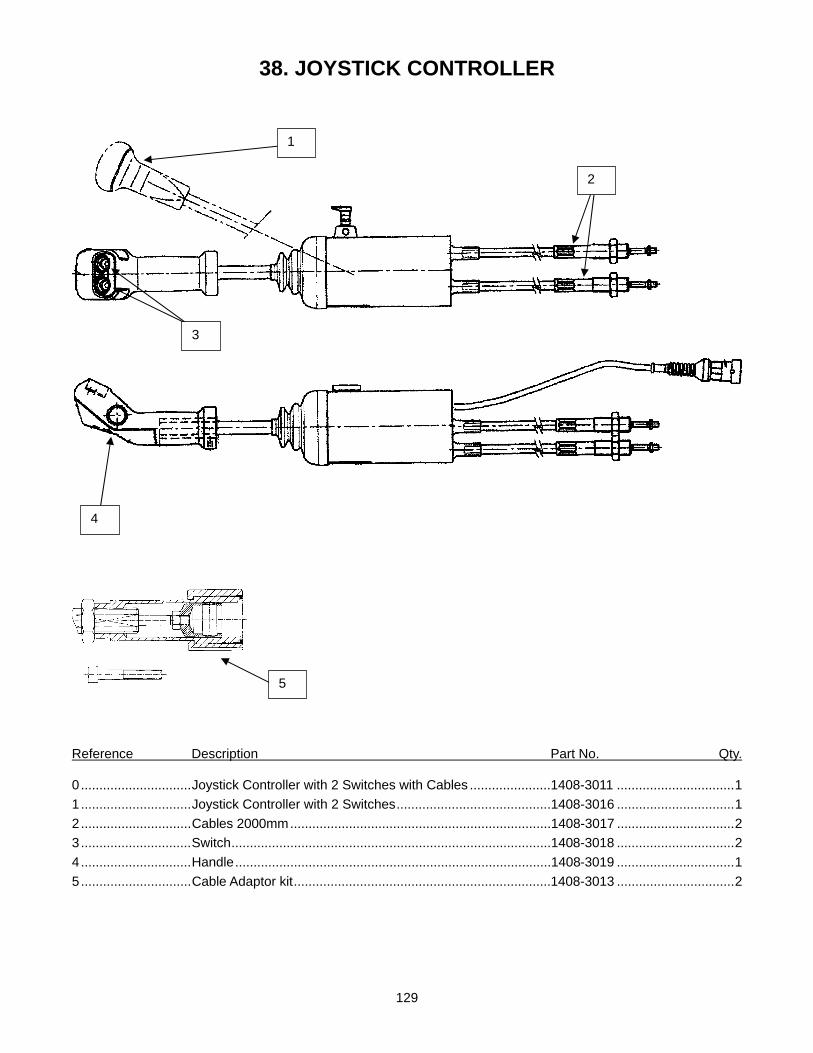
129
38. JOYSTICK CONTROLLER
Reference Description Part No. Qty.
0 ..............................Joystick Controller with 2 Switches with Cables ......................1408-3011 ................................1 1 ..............................Joystick Controller with 2 Switches..........................................1408-3016 ................................1 2 ..............................Cables 2000mm.......................................................................1408-3017 ................................2 3 ..............................Switch.......................................................................................1408-3018 ................................2 4 ..............................Handle......................................................................................1408-3019 ................................1 5 ..............................Cable Adaptor kit......................................................................1408-3013 ................................2
4
1
2
3
5

130
39. WIRING HARNESS
Reference Description Part No. Qty.
1 ..............................Joystick 3rd Function Wiring Harness.......................................1408-3012 ................................1 2 ..............................Wiring Harness (Set of 2 wires) ...............................................1408-3015 ................................1
1
2
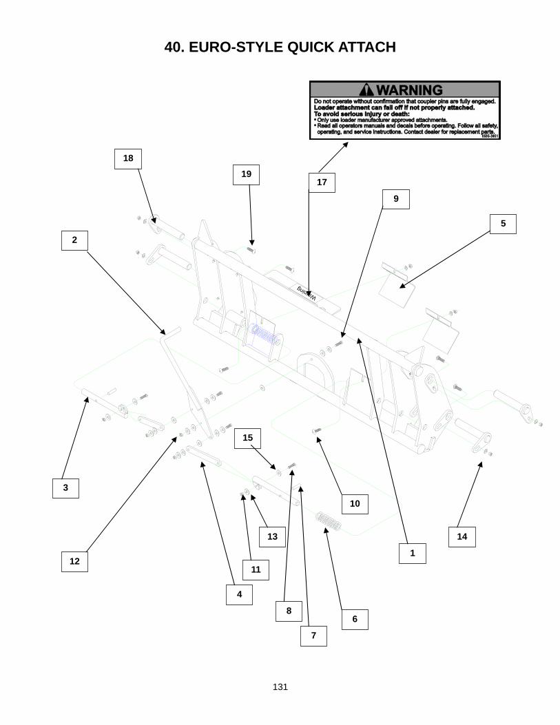
131
40. EURO-STYLE QUICK ATTACH
Warning
2
1
3
4
5
6
7
8
9
10
11 12
13 14
15
17
18 19

132
EURO-STYLE QUICK ATTACH Reference Description Part No. Qty.
1 ..............................Quick Attach Assembly.............................................................1304-4031 ................................1 2 ..............................Handle Assembly .....................................................................1304-4013 ................................1 3 ..............................Link Pin Assembly ....................................................................1304-4018 ................................2 4 ..............................Link...........................................................................................1304-4016 ................................2 5 ..............................Cover Plate ..............................................................................1304-4002 ................................2 6 ..............................Spring .......................................................................................0565-2005 ................................2 7 ..............................Spring Pin 3/8" x 1-3/4" ............................................................0561-3291 ................................2 8 ..............................Hex Head Cap Screw 5/16"-18NC x 1-1/4" Gr.5 .....................0545-2027 ................................4 9 ..............................Hex Head Cap Screw 3/8"-16NC x 1-1/2" ...............................0545-2053 ................................1 10............................Carriage Bolt 3/8"-16NC x 1" ...................................................0546-1033 ................................2 11 ............................Stover Hex Lock Nut 5/16"-18NC ............................................0546-1121 ................................4 12............................Stover Hex Lock Nut 3/8"-16NC ..............................................0546-1119.................................3 13............................Flatwasher 5/16" ......................................................................0543-2006 ................................8 14............................Flatwasher 3/8" ........................................................................0543-2007 ................................4 15............................Flatwasher Plastic ....................................................................0540-2011 ................................9 16............................Sika Flex Sealant .....................................................................0575-2004 ................................1 17............................Decal Warning..........................................................................0595-3051 ................................1 18............................Pivot Pin ...................................................................................0550-5020 ................................4 19............................Carriage Bolt, .375-16 x 1.5”....................................................0546-1118.................................4

133
41. BUCKET STANDARD Reference Description Part No. Qty.
1 ..............................Bucket 84" Standard ................................................................1300-3491 ................................1 1 ..............................Bucket 96" Standard ................................................................1300-3492 ................................1 1 ..............................Bucket 102" Standard ..............................................................1300-3493 ................................1 2 ..............................Bucket Blade 84"......................................................................1300-3504 ................................1 2 ..............................Bucket Blade 96"......................................................................1300-3477 ................................1 2 ..............................Bucket Blade 102"....................................................................1300-3508 ................................1
1
2

134
42. BUCKET HIGH CAPACITY Reference Description Part No. Qty.
1 ..............................Bucket 84" High Capacity ........................................................1300-3465 ................................1 1 ..............................Bucket 96" High Capacity ........................................................1300-3466 ................................1 1 ..............................Bucket 102" High Capacity ......................................................1300-3467 ................................1 2 ..............................Bucket Blade 84"......................................................................1300-3504 ................................1 2 ..............................Bucket Blade 96"......................................................................1300-3477 ................................1 2 ..............................Bucket Blade 102"....................................................................1300-3508 ................................1
1
2

135
Danger
Caution
Caution
43. BALE PROBE
Reference Description Part No. Qty.
1 ..............................Bale Spear Frame ....................................................................1305-2056 ................................1 2 ..............................Tine ..........................................................................................1305-2013 ................................2 3 ..............................Decal Caution...........................................................................0595-3054 ................................1 4 ..............................Decal Caution...........................................................................0595-2190 ................................1 5 ..............................Decal Danger ...........................................................................0595-3050 ................................1
1
5
4
3
2
4
3
5

136
44. GRAPPLE CYLINDER Reference Description Part No. Qty.
0 ..............................Grapple Cylinder ......................................................................3180-1000 ................................1 1 ..............................Tube Assembly.........................................................................0100-2098 ................................1 2 ..............................Rod Assembly ..........................................................................0200-2092 ................................1 3 ..............................Nut............................................................................................0530-2015 ................................1 4 ..............................Piston .......................................................................................0405-2023 ................................1 5 ..............................Head.........................................................................................0330-2019 ................................1 6 ..............................Retaining Ring..........................................................................0560-2001 ................................1 7 ..............................Retaining Ring..........................................................................0560-2008 ................................1 8 ..............................Orifice.......................................................................................0580-6205 ................................1 9 ..............................U-Cup.......................................................................................0509-2004 ................................1 10............................Seal Kit .....................................................................................0590-2053 ................................1
1
2 3
4 5
6
7
8 9
10
10
10
10
10 10

137
45. PALLET FORK
1
2 3
4
5
6 7
8
9 10 11
12 13
14
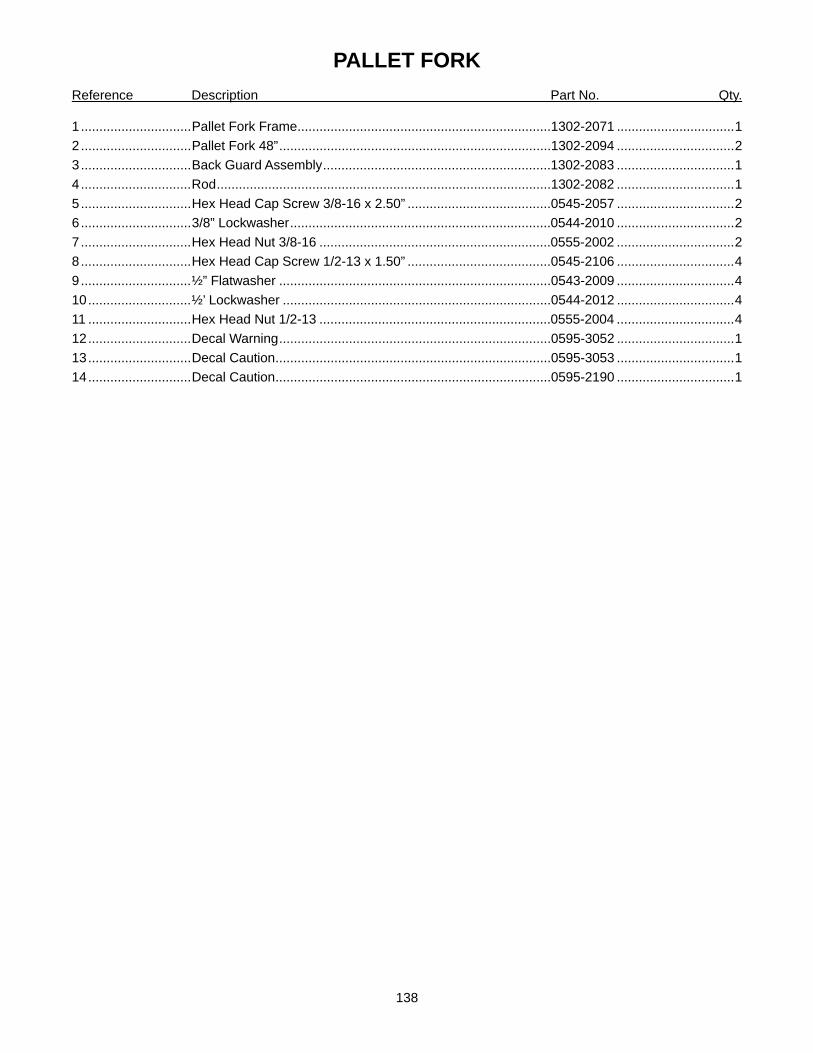
138
PALLET FORK Reference Description Part No. Qty.
1 ..............................Pallet Fork Frame.....................................................................1302-2071 ................................1 2 ..............................Pallet Fork 48”..........................................................................1302-2094 ................................2 3 ..............................Back Guard Assembly..............................................................1302-2083 ................................1 4 ..............................Rod...........................................................................................1302-2082 ................................1 5 ..............................Hex Head Cap Screw 3/8-16 x 2.50” .......................................0545-2057 ................................2 6 ..............................3/8” Lockwasher.......................................................................0544-2010 ................................2 7 ..............................Hex Head Nut 3/8-16 ...............................................................0555-2002 ................................2 8 ..............................Hex Head Cap Screw 1/2-13 x 1.50” .......................................0545-2106 ................................4 9 ..............................½” Flatwasher ..........................................................................0543-2009 ................................4 10............................½’ Lockwasher .........................................................................0544-2012 ................................4 11 ............................Hex Head Nut 1/2-13 ...............................................................0555-2004 ................................4 12............................Decal Warning..........................................................................0595-3052 ................................1 13............................Decal Caution...........................................................................0595-3053 ................................1 14............................Decal Caution...........................................................................0595-2190 ................................1

139
46. GRAPPLE ASSEMBLY
10
11
11
12
4
3
1
1
13
12
14
5
7
8
6
13
9
4
9 10
2
2
5

140
GRAPPLE ASSEMBLY Reference Description Part No. Qty.
1 ..............................Grapple Pedestal Assembly.....................................................1303-1019 ................................2 2 ..............................Grapple Swing Arm Assembly..................................................1303-1002 ................................1 3 ..............................Tine ..........................................................................................1303-1003 ................................4 4 ..............................Pivot Pin 1-1/8" x 5-5/8" ...........................................................0550-5012 ................................4 5 ..............................Pivot Pin 1-1/8" x 3-5/8" ...........................................................0550-5011 ................................2 6 ..............................Carriage Bolt 3/8"-16NC x 1-1/2" Gr5 ......................................0546-1118.................................6 7 ..............................Flatwasher 3/8" Gr8 .................................................................0540-2007 ................................6 8 ..............................Hex Nut 3/8"-16NC Stover Lock ..............................................0546-1119.................................6 9 ..............................Hex Bolt 3/4"-10NC x 2-3/4" Gr5 .............................................0545-2233 ..............................12 10............................Lockwasher 3/4" Hardened......................................................0540-2002 ..............................14 11 ............................Hex Nut 3/4"-10NC Lock..........................................................0555-2140 ..............................12 12............................Latch Pin 1" x 6".......................................................................0551-3043 ................................4 13............................Lynch Pin..................................................................................0553-4503 ................................4 14............................Grease Fitting...........................................................................0530-1038 ................................2

141
View A
View A
47. GRAPPLE HYDRAULICS
1
2
3
4
5
6
7
8
9
9
10
11
11
12
12
12 8

142
GRAPPLE HYDRAULICS Reference Description Part No. Qty.
1 ..............................Hydraulic Hose.........................................................................0582-2108508063 ....................2 2 ..............................Hydraulic Hose ........................................................................0582-2508508038 ....................2 3 ..............................Hydraulic Hose ........................................................................0582-2508508030 ....................2 4 ..............................Hose Sock 40" .........................................................................0554-2029 ................................1 5 ..............................Quick Coupler, Male.................................................................0580-6081 ................................1 6 ..............................Quick Coupler, Female ............................................................0580-6082 ................................1 7 ..............................Fitting Tee.................................................................................0586-3011 ................................2 8 ..............................Quick Coupler, Rubber Plug ....................................................0584-2003 ................................1 9 ..............................Fitting ......................................................................................0586-3108-408.........................4 10............................Fitting .......................................................................................0586-3408-508.........................2 11 ............................Hydraulic Cylinder ....................................................................3180-1000 ................................2 12............................Tie Strap Black 5/16" x 14".......................................................0554-1013 ................................5

143
Warning
48. ACCUMULATOR
2
19
6
22
14
5
11
12
3
1
18
8
16
4
9
17
21
13
9
23 24
25
7
10
26
27

144
ACCUMULATOR Reference Description Part No. Qty.
1 ..............................Accumulator .............................................................................0805-2001 ................................1 2 ..............................Solenoid Valve .........................................................................0580-6283 ................................1 3 ..............................Solenoid Strap..........................................................................1103-3020 ................................1 4 ..............................Accumulator Switch Plate ........................................................1213-2004 ................................1 5 ..............................Accumulator Mount Plate.........................................................1103-3026 ................................2 6 ..............................Hydraulic Adapter Bulkhead.....................................................0586-3026 ................................1 7 ..............................Hydraulic Adapter 2.7” Long ....................................................0586-3022 ................................1 8 ..............................U-Bolt 1/4"-20NC x .63" ...........................................................0546-1124 ................................2 9 ..............................Stover Locknut 1/4"-20NC........................................................0546-1041 ................................6 10............................O-ring .......................................................................................0520-3002 ................................1 11 ............................Carriage Bolt ¼”-20 x 2.25”......................................................0546-1148 ................................2 12............................Flatwasher 3/8" Hardened .......................................................0540-2007 ................................4 13............................Lockwasher 3/8".......................................................................0544-2010 ................................4 14............................Hex Head Cap Screw 3/8"-16NC x 1-1/2" Gr.5 .......................0545-2053 ................................4 15............................Plastic Tie Strap 5/16" x 14".....................................................0554-1013 ................................2 16............................Switch.......................................................................................1410-1000 ................................1 17............................Loader Arm Wiring Harness.....................................................1410-1023 ................................1 18............................Switch Wiring Harness.............................................................1410-1002 ................................1 19............................Solenoid Wiring Harness .........................................................1410-1021 ................................1 20............................Decal Warning..........................................................................0595-3085 ................................1 21............................¼” Convoluted Sleeving 40”.....................................................1410-1016 ................................1 22............................Hydraulic Adapter 90˚ ..............................................................0586-3108-408.........................1 23............................Hydraulic Hose Assembly ........................................................0582-2508848028 ....................1 24............................Hydraulic Hose Assembly ........................................................0582-2808848016 ....................1 25............................Hydraulic Hose Assembly ........................................................0582-2128808012 ....................1 26............................Hex Head Nut 5/8”-18 ..............................................................0555-2023 ................................2 27............................Lockwasher 5/8”.......................................................................0544-2014 ................................2

145
49. 3rd FUNCTION HOSE KIT
1 2
3 5
4
5
4
6
7
8
9
10
11
13
12 14
15
16
17

146
3RD FUNCTION HOSE KIT Reference Description Part No. Qty.
1 ..............................Hose Cover ..............................................................................1212-2017 ................................1 2 ..............................Hex Head Cap Screw 5/16”-18 x 2.25” ....................................0545-2031 ................................1 3 ..............................Hex Head Cap Screw 5/16”-18 x .75” ......................................0545-2024 ................................1 4 ..............................Flatwasher 5/16” ......................................................................0543-2006 ................................2 5 ..............................Lockwasher 5/16”.....................................................................0544-2009 ................................2 6 ..............................Sponge Rubber 4.25”...............................................................0554-2010 ................................1 7 ..............................Sponge Rubber 3.5”.................................................................0554-2010 ................................1 8 ..............................Hydraulic Hose Assembly ........................................................0582-2508528226 ....................2 9 ..............................Hose Sock 1.59” x 30” .............................................................0554-2027 ................................1 10............................Hydraulic Bulkhead Adapter.....................................................0586-3008 ................................2 11 ............................O-Ring......................................................................................0520-3002 ................................2 12............................Female Quick Coupler .............................................................0580-6082 ................................1 13............................Male Quick Coupler..................................................................0580-6081 ................................1 14............................Rubber Coupler Plug................................................................0584-2003 ................................1 15............................Tie Strap Black .14” x 5.5”........................................................0554-2008 ................................2 16............................Tie Strap White .14” x 5.5” .......................................................0554-2028 ................................2 17............................Plastic Tie Strap .313” x 14” .....................................................0554-1013 ................................4

147
50. BUCKET LEVEL INDICATOR Reference Description Part No. Qty.
1 ..............................BLI Rod Assembly....................................................................1403-3083 ................................1 2 ..............................BLI Tube Assembly ..................................................................1403-3086 ................................1 3 ..............................Hex Head Cap Screw 5/16" x 1-3/4"........................................0545-2029 ................................1 4 ..............................Hex Head Cap Screw 5/16" x 1/2" ...........................................0545-2022 ................................1 5 ..............................Lockwasher 5/16".....................................................................0544-2009 ................................2 6 ..............................Flatwasher 5/16" ......................................................................0543-2006 ................................2
1
3
5
6
4
5
6
2