Embed Size (px)
Citation preview

122017 FK328
OPERATOR AND PARTS MANUAL
Grain CleanerModel 480


480 Grain Cleaner
i
Table Of Contents
Warranty Registration Form 1
Introduction 3Owner’s Information 5
Equipment Identification 6
Safety 7Safety Instructions 9
Fire Prevention 11
Equipment And Safety Signs (Decals) 13
Safety Sign-Off Form 15
Assembly 17
Preparing For Assembly 19
Frame And Wheel Assembly 20
Pulley Assembly 22
Motor Mount Assembly 22
Motor Assembly (Motor Not Supplied) 22
Belt Routing 22
Front Guard Assembly 24
Rear Guard Assembly 24
Drum Assembly 24
Trash Pan Assembly (GC482 Option) 26
Belt Routing (GC482 Option) 26
Operation 29
Pre - Operation Checklist 31
Theory Of Operation 32
Transporting 34
Maintenance 35
Service Schedule 37
Lubrication 38
Belt Tension 39
Tire Pressure 39
Safety Sign (Decal) Installation 40
Manufacturer’s Statement: For technical reasons, Buhler Industries Inc. reserves the right to modify machinery design and specifications provided herein without any preliminary notice. Information provided herein is of descriptive nature. Performance quality may depend on soil fertility, applied agricultural techniques, weather conditions, and other factors.

480 Grain Cleaner
ii
Storage And Return To Service 40
Parts Identification 41
General Parts Information 42
Frame Assembly 42
Guard Assembly 44
Pulley Assembly 46
Trash Pan (GC482 Option) 48
Drum And Screen Assembly 50
Utility Auger 52
Specifications And Shipping Kit Numbers 55
Specifications 57
Shipping Kit And Bundle Numbers 57
Hardware Torque Values 58
Warranty 61
Farm King Base Limited Warranty 63

Warranty Registration Form - 480 Grain Cleaner
1
Warranty Registration Form
This form must be filled out by the dealer and signed by both the dealer and the customer at the time of delivery.
Customer Name:
Customer Address:
City: Prov / State:
Postal / Zip Code: Phone:
Dealer Name:
Dealer Address:
City: Prov / State:
Postal / Zip Code: Phone:
Equipment Model: Serial Number: Delivery Date:
I have thoroughly instructed the buyer on the above described equipment which review included the Operator and Parts Manual content, equipment care, adjustments, safe operation and applicable warranty policy.
Bearings Turn Freely
Belt Tension Checked
All Fasteners Are Tight
Lubricate Machine
Safety Chain On Hitch
All Decals Installed
Guards And Shields Installed And Secure
Review Operating And Safety Instructions
Date: Dealer Rep. Signature:
The above equipment and Operator And Parts Manual have been received by me and I have been thoroughly instructed as to care, adjustments, safe operation and applicable warranty policy.
Date: Customer / Owner Signature:
Remove this Warranty Registration Form from the Operator And Parts Manual. Make two copies of the form. Send original Warranty Registration Form to Farm King. Give one copy to the customer and the dealer will keep one copy.
Dealer Inspection Report Safety

Warranty Registration Form - 480 Grain Cleaner
2

Introduction - 480 Grain Cleaner
3
IntroductionThis Operator And Parts Manual was written to give the owner / operator instructions on the safe operation, maintenance and part identification of the Farm King equipment. READ AND UNDERSTAND THIS OPERATOR AND PARTS MANUAL BEFORE OPERATING YOUR FARM KING EQUIPMENT. If you have any questions, see your Farm King dealer. This manual may illustrate options and accessories not installed on your Farm King equipment.
Owner’s Information 5Serial Number Location 5
Manual Storage 5
Equipment Identification 6Component Location 6

Introduction - 480 Grain Cleaner
4

Introduction - 480 Grain Cleaner
5
Owner’s InformationThank you for your decision to purchase a Farm King 480 Grain Cleaner. To ensure maximum performance of your equipment, it is mandatory that you thoroughly study the Operator and Parts Manual and follow the recommendations. Proper operation and maintenance are essential to maximize equipment life and prevent personal injury.
Operate and maintain this equipment in a safe manner and in accordance with all applicable local, state, and federal codes, regulations and / or laws. Follow all onproduct labeling and instructions.
Make sure that all personnel have read this Operator and Parts Manual and thoroughly understand safe and correct operating, installation and maintenance procedures.
Farm King is continually working to improve its products. Farm King reserves the right to make any improvements or changes as deemed practical and possible without incurring any responsibility or obligation to make any changes or additions to equipment sold previously.
Although great care has been taken to ensure the accuracy of this publication, Farm King, makes no warranty or guarantee of any kind, written or expressed, implied or otherwise with regard to the information contained within this manual. Farm King assumes no responsibility for any errors that may appear in this manual and shall not be liable under any circumstances for incidental, consequential or punitive damages in connection with, or arising from the use of this manual.
Keep this manual available for frequent reference. All new operators or owners must review the manual before using the equipment and annually thereafter.
Contact your Farm King Dealer if you need assistance, information, or additional copies of the manual. Visit our website at www.farm-king.com for a complete list of dealers in your area.
The directions left, right, front and rear, as mentioned throughout this manual, are as viewed from the rear of the equipment.
Serial Number Location
Please enter the model and serial number in the space provided for easy reference.
Figure 1
Model Number:
Serial Number:
The serial number plate (Item 1) [Figure 1] is located on the rear frame.
Always use your serial number when requesting information or when ordering parts.
Manual Storage
Figure 2
The operator and parts manual and other documents can be stored in the canister (Item 1) [Figure 2].
1
1

Introduction - 480 Grain Cleaner
6
Equipment Identification
Component Location
INTAKE PAN
DRUM SHIELD
INNER CONE
INTAKE AUGER
SUPPORT
INTAKE AUGER MOUNT
OUTER DRUM
TRASH OUTLET
PULLEY GUARD
WHEEL
SUPPORT STANDJACKHITCH / SAFETY
CHAIN
DISCHARGE PAN

Safety - 480 Grain Cleaner
7
Safety
Safety Instructions 9Safe Operation is The Operator’s Responsibility 9
Safe Operation Needs A Qualified Operator 9
Use Safety Rules 10
Machine Requirements And Capabilities 10
Transport Safety 11
Fire Prevention 11
Maintenance 11
Operation 11
Starting 11
Electrical 12
Hydraulic System 12
Fueling 12
Fire Extinguishers 12
Equipment And Safety Signs (Decals) 13
Safety Sign-Off Form 15

Safety - 480 Grain Cleaner
8

Safety - 480 Grain Cleaner
9
Safety InstructionsSafe Operation is The Operator’s Responsibility
Safety Alert Symbol
This symbol with a warning statement means: “Warning, be alert! Your safety is involved!” Carefully read the message that follows.
CAUTIONThe signal word CAUTION on the machine and in the manuals indicates a potentially hazardous situation which, if not avoided, may result in minor or moderate injury. It may also be used to alert against unsafe practices.
DANGERThe signal word DANGER on the machine and in the manuals indicates a hazardous situation which, if not avoided, will result in death or serious injury.
WARNINGThe signal word WARNING on the machine and in the manuals indicates a potentially hazardous situation which, if not avoided, could result in death or serious injury.
IMPORTANTThis notice identifies procedures which must be followed to avoid damage to the machine.
Safe Operation Needs A Qualified Operator
WARNINGOperators must have instructions before operating the machine. Untrained operators can cause injury or death.
For an operator to be qualified, he or she must not use drugs or alcohol which impair alertness or coordination while working. An operator who is taking prescription drugs must get medical advice to determine if he or she can safely operate a machine and the equipment.
Understand the written instructions, rules and regulations:
• The written instructions from Farm King include the Warranty Registration, Dealer Inspection Report, Operator And Parts Manual and machine signs (decals).
• Check the rules and regulations at your location. The rules may include an employer’s work safety requirements. Regulations may apply to local driving requirements or use of a Slow Moving Vehicle (SMV) emblem. Regulations may identify a hazard such as a utility line.
Have Training with Actual Operation:
• Operator training must consist of a demonstration and verbal instruction. This training is given by the machine owner prior to operation.
• The new operator must start in an area without bystanders and use all the controls until he or she can operate the machine safely under all conditions of the work area. Always fasten seat belt before operating.
Know the Work Conditions:
• Clear working area of all bystanders, especially small children and all obstacles that might be hooked or snagged, causing injury or damage.
• Know the location of any overhead or underground power lines. Call local utilities and have all underground power lines marked prior to operation.
• Wear tight fitting clothing. Always wear safety glasses when doing maintenance or service.

Safety - 480 Grain Cleaner
10
Use Safety Rules
• Read and follow instructions in this manual and the tractor’s Operators Manual before operating.
• Under no circumstances should young children be allowed to work with this equipment.
• This equipment is dangerous to children and persons unfamiliar with its operation.
• In addition to the design and configuration of equipment, hazard control and accident prevention are dependent upon the awareness, concern, prudence and proper training of personnel involved in the operation, transport, maintenance and storage of equipment.
• Check that the equipment is securely fastened to the tractor / towing vehicle.
• Make sure all the machine controls are in the NEUTRAL position before starting the machine.
• Operate the equipment only from the operator’s position.
• Operate the equipment according to the Operator And Parts Manual.
• When learning to operate the equipment, do it at a slow rate in an area clear of bystanders, especially small children.
• DO NOT permit personnel to be in the work area when operating the equipment.
• The equipment must be used ONLY on approved tractors / transport vehicles.
• DO NOT modify the equipment in any way. Unauthorized modification may impair the function and / or safety and could affect the life of the equipment.
• Stop tractor engine, place all controls in neutral, set park brake, remove ignition key and wait for all moving parts to stop before servicing, adjusting, repairing, unplugging or filling.
• DO NOT make any adjustments or repairs on the equipment while the machine is running.
• Keep shields and guards in place. Replace if damaged.
• Keep hands, feet, hair and clothing away from all moving parts.
Machine Requirements And Capabilities
• Fasten seat belt securely. If equipped with a foldable Roll-Over Protective Structure (ROPS), only fasten seat belt when ROPS is up and locked. DO NOT wear seat belt if ROPS is down.
• Stop the machine and engage the parking brake. Install blocks in front of and behind the rear tires of the machine. Install blocks underneath and support the equipment securely before working under raised equipment.
• Keep bystanders clear of moving parts and the work area. Keep children away.
• Use increased caution on slopes and near banks and ditches to prevent overturn.
• Make certain that the Slow Moving Vehicle (SMV) emblem is installed so that it is visible and legible. When transporting the equipment, use the flashing warning lights (if equipped) and follow all local regulations.
• Operate this equipment with a machine equipped with an approved Roll-Over Protective Structure (ROPS). Always wear seat belt when the ROPS is up. Serious injury or death could result from falling off the machine.
• Before leaving the operator’s position:
1. Always park on a flat level surface.
2. Place all controls in neutral.
3. Engage the parking brake.
4. Stop engine.
5. Wait for all moving parts to stop.
• Carry passengers only in designated seating areas. Never allow riders on the machine or equipment. Falling off can result in serious injury or death.
• Start the equipment only when properly seated in the operator’s seat. Starting a machine in gear can result in serious injury or death.
• Operate the machine and equipment from the operator’s position only.
• The parking brake must be engaged before leaving the operator’s seat. Roll-away can occur because the transmission may not prevent machine movement.
Safety - 480 Grain Cleaner
11
Fire Prevention
Maintenance
• The machine and some equipment have components that are at high temperatures under normal operating conditions. The primary source of high temperatures is the engine and exhaust system. The electrical system, if damaged or incorrectly maintained, can be a source of arcs or sparks.
• Flammable debris (leaves, straw, etc.) must be removed regularly. If flammable debris is allowed to accumulate, it can cause a fire hazard. Clean often to avoid this accumulation. Flammable debris in the engine compartment is a potential fire hazard. The operator’s area, engine compartment and engine cooling system must be inspected every day and cleaned if necessary to prevent fire hazards and overheating.
• All fuels, most lubricants and some coolant mixtures are flammable. Flammable fluids that are leaking or spilled onto hot surfaces or onto electrical components can cause a fire.
Operation
• The Farm King machine must be in good operating condition before use.
• Check all of the items listed on the service schedule under the 8 hour column before operation. (See Maintenance section)
• Do not use the machine where exhaust, arcs, sparks or hot components can contact flammable material, explosive dust or gases.
Starting
• Do not use ether or starting fluids on any engine that has glow plugs. These starting aids can cause explosion and injure you or bystanders.
• Use the procedure in the tractor’s operator’s manual for connecting the battery and for jump starting.
Transport Safety
• Do not exceed 20 mph (32 kph). Reduce speed on rough roads and surfaces.
• Comply with state and local laws governing highway safety and movement of machinery on public roads.
• The use of flashing amber lights is acceptable in most localities. However, some localities prohibit their use.
• Local laws should be checked for all highway lighting and marking requirements.
• Always yield to oncoming traffic in all situations and move to the side of the road so any following traffic may pass.
• Always enter curves or drive up or down hills at a low speed and at a gradual steering angle.
• Never allow riders on either tractor or equipment.
• Keep tractor / towing vehicle in a lower gear at all times when traveling down steep grades.
• Maintain proper brake settings at all times (if equipped).

Safety - 480 Grain Cleaner
12
Electrical
• Check all electrical wiring and connections for damage. Keep the battery terminals clean and tight. Repair or replace any damaged part or wires that are loose or frayed.
• Battery gas can explode and cause serious injury. Do not jump start or charge a frozen or damaged battery. Keep any open flames or sparks away from batteries. Do not smoke in battery charging area.
Hydraulic System
• Check hydraulic tubes, hoses and fittings for damage and leakage. Never use open flame or bare skin to check for leaks. Hydraulic tubes and hoses must be properly routed and have adequate support and secure clamps. Tighten or replace any parts that show leakage.
• Always clean fluid spills. Do not use gasoline or diesel fuel for cleaning parts. Use commercial nonflammable solvents.
Fueling
• Stop the engine and let it cool before adding fuel. No smoking! Do not refuel a machine near open flames or sparks. Fill the fuel tank outdoors.
Fire Extinguishers
• Know where fire extinguishers and first aid kits are located and how to use them. Inspect the fire extinguisher and service the fire extinguisher regularly. Obey the recommendations on the instructions plate.

Safety - 480 Grain Cleaner
13
Equipment And Safety Signs (Decals)Follow the instructions on all the signs (decals) that are on the equipment. Replace any damaged signs (decals) and be sure they are in the correct locations. Equipment signs are available from your Farm King equipment dealer.
Figure 3
6
1
3
2748
5
4
5

Safety - 480 Grain Cleaner
14
Equipment And Safety Signs [Figure 3]
86547711 - SMV EMBLEM CAUTION (Item 1)
910625 - FK 1.85 X 12 (Item 2)
911389 - 480 GC (Item 3)
918272 - DANGER ROTATING DRIVELINE (Item 4)
918272
-All driveline, tractor and equipment shields in place.-Drivelines securely attached at both ends.-Driveline shields that turn freely on driveline.
DANGER
ROTATING DRIVELINECONTACT CAN CAUSE DEATH
KEEP AWAYDO NOT OPERATE WITHOUT:
966699 - GREASE (Item 5)
967053 - REFLECTIVE 2 X 9 RED (Item 6)
967382 - CAUTION (Item 7)
SZ06023 - WARNING, SHIELD (Item 8)

Safety - 480 Grain Cleaner
15
Safety Sign-Off Form
WARNINGInstructions are necessary before operating or servicing equipment. Read and understand the Operator And Parts Manual and safety signs (decals) on equipment. Follow warnings and instructions in the manuals when making repairs, adjustments or servicing. Check for correct function after adjustments, repairs or service. Untrained operators and failure to follow instructions can cause injury or death.
Farm King follows the general Safety Standards specified by the American Society of Agricultural and Biological Engineers (ASABE) and the Occupational Safety and Health Administration (OSHA). Anyone who will be operating and / or maintaining the equipment must read and clearly understand ALL Safety, Operating and Maintenance information presented in this manual.
Annually review this information before the season start-up and make these periodic reviews of SAFETY and OPERATION a standard practice for all of your equipment. An untrained operator is unqualified to operate this machine.
The following sign-off sheet is provided for your record and to show that all personnel who will be working with the equipment have read and understand the information in this Operator And Parts Manual and have been instructed in the operation of the equipment.
SIGN-OFF SHEET
Date Employee’s Signature Employer’s Signature

Safety - 480 Grain Cleaner
16

Assembly - 480 Grain Cleaner
17
Assembly
Preparing For Assembly 19
Frame And Wheel Assembly 20
Pulley Assembly 22
Motor Mount Assembly 22
Motor Assembly (Motor Not Supplied) 22
Belt Routing 22
Front Guard Assembly 24
Rear Guard Assembly 24
Drum Assembly 24
Trash Pan Assembly (GC482 Option) 26
Belt Routing (GC482 Option) 26

Assembly - 480 Grain Cleaner
18

Assembly - 480 Grain Cleaner
19
Preparing For Assembly
IMPORTANTEquipment may be shipped without some components installed due to transport restrictions.
• Using the packing list, locate and count the individual components and verify that you have received the correct number of each component.
• Check all the components for damage. If any components are damaged or missing, contact your Farm King dealer.
WARNING
AVOID INJURY OR DEATHBefore moving the tractor, look in all directions and make sure no bystanders, especially small children are in the work area. Do not allow anyone between the tractor and the equipment when backing up to the equipment for connecting.
Move the tractor, equipment and components to an area large enough for assembly.
WARNINGAVOID INJURY OR DEATH
Before you leave the operator’s position:
• Always park on a flat level surface.
• Place all controls in NEUTRAL.
• Engage the park brake.
• Stop the engine and remove the key.
• Wait for all moving parts to stop.
Park the tractor / equipment on a flat level surface.
Place all controls in neutral, engage the park brake, stop the engine and wait for all moving parts to stop. Leave the operator’s position.
WARNINGAVOID INJURY OR DEATH
Wear safety glasses to prevent eye injury when any of the following conditions exist:
• When fluids are under pressure.
• Flying debris or loose material is present.
• Engine is running.
• Tools are being used.
IMPORTANTThe directions front, rear, right, and left are viewed as the operator sitting in the tractor with the equipment hitched to the tractor.

Assembly - 480 Grain Cleaner
20
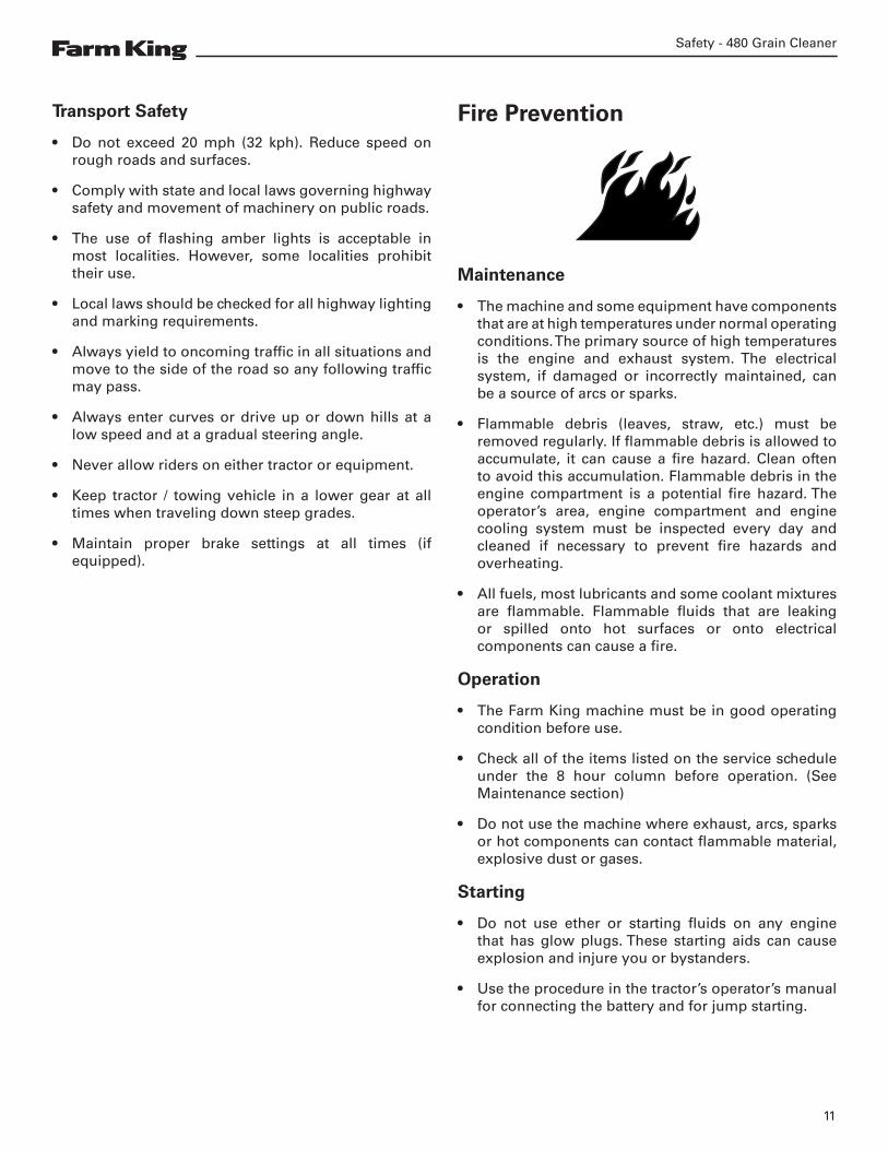
Frame And Wheel AssemblyPosition the front and rear frame weldments (Item 1, 2) with the right and left frame sides (Item 3, 4). Attach using 1/2” x 1-1/4” hex bolts and 1/2” lock nuts. Frame ends and sides must be squared before tightening bolts [Figure 4].
Position wheels (Item 5) on the axle / hub assembly (Item 6). Attach using 1/2” x 1-1/4” wheel bolts. Torque wheel bolts to 80 ft.-lbs. [Figure 4].
Lift the frame using an adequate hoist. Position axle and wheel assembly under the frame.
Position the front and rear axle braces (Item 7, 8) between the frame sides and axle. Attach axle braces using 1/2” x 1-1/4” hex bolts and 1/2” lock nuts [Figure 4].
Position the center axle braces (Item 9) between the frame sides and axle. Attach axle braces using 1/2” x 1-1/4” hex bolts, 1/2” flat washers, and 1/2” lock nuts [Figure 4].
Position the frame braces (Item 10) between the front axle braces (Item 7) and front frame weldment (Item 1). Attach frame braces using 1/2” x 1-1/4” hex bolts, 1/2” flat washers, and 1/2” lock nuts [Figure 4].
Attach hitch weldment (Item 11) to the frame using 1/2” x 1-1/4” hex bolts and 1/2” lock nuts [Figure 4].
Attach the left and right hitch braces (Item 12, 13) between the hitch weldment and front frame using 1/2” x 1-1/4” hex bolts and 1/2” lock nuts [Figure 4].
IMPORTANTAll bolts connecting the frame must be firmly tightened to proper torque. Any loose bolts could result in the frame separating while towing the cleaner.
Slide the support stands (Item 14) into the front frame weldment mounts. Secure using stand pin and clip [Figure 4].
Attach the manual holder (Item 15) to the top of the front frame weldment using 5/16” x 1” hex bolts and 5/16” lock nuts [Figure 4].
Connect the jack stand (Item 16) to the hitch weldment [Figure 4].
Attach the trash chute mount (Item 17) to the rear frame weldment [Figure 4].
Attach one pillow bearing (Item 18) to the top of the rear frame weldment using 1/2” x 1-3/4” hex bolts, 1/2” flat washers, and 1/2” lock nuts [Figure 4].
Attach one pillow bearing (Item 19) to the underside of the front frame weldment using 1/2” x 1-3/4” hex bolts, 1/2” flat washers, and 1/2” lock nuts [Figure 4].
Assembly - 480 Grain Cleaner
21
Figure 4
2
18
17
8
79
9
4
3
10
14
12
16
1113
1
1519
5
6
FRONT

Assembly - 480 Grain Cleaner
22
Pulley AssemblySlide two pillow bearings (Item 1) onto the reducer shaft (Item 2). Attach the two pillow bearings to the bottom of the reducer mount (Item 3) using 1/2” x 1-3/4” hex bolts, 1/2” flat washers, and 1/2” lock nuts [Figure 6].
Slide one 3” double pulley (Item 4) onto the rear end of the reducer shaft. Attach with key and two Ø3/8” x 3/8” socket set screw [Figure 6].
Slide one 12” double pulley (Item 5) onto the front end of the reducer shaft. Attach pulley using one 1/4” x 2-1/2” key and two Ø3/8” x 1/2” socket set screws [Figure 6].
Slide one idler plate (Item 6), one shaft bushing (Item 7), and one idler plate (Item 8) onto the idler shaft (Item 9). Attach using 1/4” x 2” cotter pin [Figure 6].
Position two idler pulleys (Item 10) and three 5/8” flat washers (Item 11) between the ends of the idler plates (Item 6, 8). Place the washers between the pulleys. Attach washers and pulleys to idler plates using one 5/8” x 4” hex bolt and 5/8” lock nut [Figure 6].
Connect two tightener springs (Item 12) to the idler plates (Item 6, 8) [Figure 6].
Motor Mount AssemblyPosition the motor mount (Item 13) on the front frame with two motor mount clamps (Item 14). Attach motor mount and clamps using 3/8” x 1-1/4” hex bolts and 3/8” lock nuts [Figure 6].
The tightener hole in the side of the motor mount must face the tightener bracket welded to the rear frame.
Connect the 1/2” x 4” belt tightener set screw (Item 15) between the motor mount and the welded bracket on the frame [Figure 6].
Motor Assembly (Motor Not Supplied)Attach the motor guard (Item 16) and 3 HP electric motor (not shown) to the motor mount (Item 13) using 5/16” x 1” hex bolts, 5/16” flat washers, and 5/16” lock nuts [Figure 6].
Motor shaft must face front. Motor guard must face rear.
Position one 3” double pulley on the electric motor shaft. Attach using one key and two Ø3/8” x 3/8” socket set screws (not shown).
Belt RoutingFigure 5
Route two B-87 V-belts (Item 1) around the motor double pulley and 12” double pulley [Figure 5].
Tighten belt using belt tightener set screw (Item 15) [Figure 6].
Route two B-164 V-belts (Item 2) around the outer drum assembly, the idler pulleys, and 3” double pulley [Figure 5].
Tighten belt by connecting the belt tightener springs (Item 12) to the frame [Figure 6].
2
1
REAR VIEW

Assembly - 480 Grain Cleaner
23
Figure 6
16
14
153
13
5
4
6
12
8
7 10
11
9
2
1
FRONT
FRONT

Assembly - 480 Grain Cleaner
24
Front Guard AssemblyAttach the intake pan (Item 1) to the underside of the front frame weldment using 3/8” x 1” hex bolts, 5/16” flat washers, and 3/8” lock nuts [Figure 7].
Position the front pulley guard (Item 2) over the pulley assembly. Attach pulley guard to the front frame mounts using 5/16” x 3/4” hex bolts, 5/16” flat washers, and 5/16” lock nuts [Figure 7].
Attach the swivel arm assembly (Item 3) to the top right of the front frame using 1/2” x 1” hex bolts, 1/2” lock washers, and 1/2” hex nuts [Figure 7].
Attach the intake auger connector plate (Item 4) to the swivel arm assembly using one pin and clip. Attach the offset connector (Item 5) to the plate (Item 4) using 3/8” x 1” hex bolts and 3/8” lock nuts [Figure 7].
Attach the safety chain (Item 6) to the hitch using 3/4” x 2-1/4” hex bolt and 3/4” lock nut [Figure 7].
Rear Guard AssemblyPosition the discharge pan weldment (Item 7) within the rear frame. Attach the top of the weldment to the frame using 1/4” x 3/4” self taping screws (Item 8). Attach the sides of the weldment to the frame using 5/16” x 3/4” hex bolts (Item 9), 5/16” flat washers, and 5/16” lock nuts.[Figure 7]
Position the discharge chute (Item 10) on the discharge pan weldment (Item 7). Attach top end of chute to weldment using 1/4” x 3/4” hex bolts and 1/4” lock nuts. Attach bottom end of the chute to the rear frame using 1/4” x 3/4” hex bolts, 5/16” flat washers, and 1/4” lock nuts [Figure 7].
Position the rear drum shield weldment (Item 11) on top of the rear frame. Attach the weldment to the rear frame using 1/4” x 3/4” self taping screws (Item 12). Attach the brackets using 3/8” x 1” hex bolts (Item 13), 5/16” flat washers, and 3/8” lock nuts. Attach the sides of the weldments using 1/4” x 3/4” hex bolts (Item 14), 5/16” flat washers, and 1/4” lock nuts [Figure 7].
Attach the intake auger support (Item 15) to the right side of the rear frame. Attach using 3/8” x 1” hex bolts and 3/8” lock nuts. Attach one half clamp (Item 16) using 3/8” x 1” hex bolt, washer, and wing nut [Figure 7].
Drum AssemblyAssemble the inner cone (Item 17), outer drum (Item 18), and center drum shaft (Item 19). Install assembly and center drum shaft to pillow bearings on main frame [Figure 7].
Assemble the inner cone screen (Item 20) and outer drum screen (Item 21) [Figure 7].
Attach the screen sections using 1/4” x 3/4” self-tap screws and flat washers. Strap the ends of the screen sections to the rear and center rings using the two straps [Figure 7].
Tighten straps with 1/4” x 2-1/2” round head bolts and 1/4” square nuts. After strapping, the screen is tightened by attaching the remaining self-tapping screws [Figure 7].
All the strap bolts holding the screens should be turned so the end of the bolt trails the direction of drum rotation [Figure 7].

Assembly - 480 Grain Cleaner
25
Figure 7
11
16
15
7
10
8914
1312
1
3
5
4
6
2
19
17
18
ALIGN WELDING SEAMS
21
20
FRONT
FRONT

Assembly - 480 Grain Cleaner
26
Trash Pan Assembly (GC482 Option)Attach the two trash pan ends (Item 1, 2) and trash pan sides (Item 3, 4) to the trough (Item 5) using 1/4” x 3/4” hex bolts, 5/16” flat washers, and 1/4” lock nuts [Figure 9].
The stub shaft of the trough flighting must face front.
Slide the trash pan assembly underneath the frame. Rest trash pan on frame edges.
Position left and right trash pan side panels (Item 6, 7) on the frame edges. Align holes along bottom of side panels with trash pan holes. Attach side panels and trash pan to frame using 1/4” x 3/4” self-tapping screws [Figure 9].
Attach top corners of side panels to frame mounts using 1/4” x 3/4” hex bolts, 5/16” flat washers, and 1/4” lock nuts.
Slide one 6” single pulley (Item 8) onto the trough flighting stub shaft. Attach pulley using one key and two Ø5/16” x 1/4” socket set screws [Figure 9].
Slide one 3” single pulley (Item 9) onto the end of the reducer shaft. Attach pulley using one key and two Ø3/8” x 1/2” socket set screws [Figure 9].
Attach one 3” idler pulley (Item 10) to the slotted bracket welded to the front frame using one 5/8” x 3” hex bolt, 5/8” flat washers, and 5/8” lock nut [Figure 9].
NOTE: Use 5/8” flat washers as required on both sides of idler pulley to align with belt assembly.
Belt Routing (GC482 Option)Figure 8
Route one B-37 V-belt (Item 1) around the 6” single pulley (Item 2) on flighting stub shaft and the 3” single pulley (Item 3) on the reducer shaft [Figure 8].
The belt must pass under the idler pulley. Adjust tension by moving the idler pulley on the slotted bracket and tightening hardware.
2
3
1
REAR VIEW

Assembly - 480 Grain Cleaner
27
Figure 9
910
4
7
6
31
5 8
2
FRONT
FRONT

Assembly - 480 Grain Cleaner
28

Operation - 480 Grain Cleaner
29
Operation
Pre - Operation Checklist 31
Theory Of Operation 32
Operation 32
Transporting 34

Operation - 480 Grain Cleaner
30

Operation - 480 Grain Cleaner
31
Pre - Operation ChecklistBefore operating the equipment for the first time and each time thereafter, check the following items:
1. Lubricate the equipment per the schedule outline in the Maintenance Section.
2. Check the equipment for damaged, loose or missing parts. Repair as needed before operation.
3. Use only a tractor of adequate power and weight to pull the machine.
4. Check the drums. Remove any twine, wire or other material that has become entangled.
5. Check belt tension.
6. Check that all bearings turn freely. Replace any that are rough or seized.
7. Make sure that all guards and shields are in place, secured and functioning as designed.
WARNING
AVOID INJURY OR DEATHBefore moving the tractor, look in all directions and make sure no bystanders, especially small children are in the work area.
Do not allow anyone between the tractor and the equipment when backing up to the equipment for connecting.
WARNING
AVOID INJURY OR DEATHKeep fingers and hands out of pinch points when connecting and disconnecting equipment.
WARNINGAVOID INJURY OR DEATH
Before you leave the operator’s position:
• Always park on a flat level surface.
• Place all controls in NEUTRAL.
• Engage the park brake.
• Stop the engine and remove the key.
• Wait for all moving parts to stop.

Operation - 480 Grain Cleaner
32
Theory Of OperationThe Farm King 480 Grain Cleaner handles up to 2500 bushels per hour. The 480 Grain Cleaner also uses two stage screening. Trash and fines are discharged onto the ground and cleaned grain discharged from the chute [Figure 10].
The Farm King 482 Grain Cleaner is equipped with an optional trash pan. The trash pan collects and separates using an auger [Figure 11].
CAUTION• Read operator and parts manual before operating
the implement.
• Do not permit riders.
• Keep all guards and shields in place.
• Keep hands, feet, clothing and hair away from moving parts.
• Stop engine, set brake, remove key and wait for all moving parts to stop before servicing, adjusting, repairing and unplugging.
• Remove bystanders, especially children, before starting or while operating.
• Block up before working beneath unit.
• Review safety instructions annually.
IMPORTANT3 HP 1725 RPM electric motor is recommended to drive the cleaner.
The electric motor with weatherproof switch must be supplied by the customer.
Consult electric motor manual for proper operation.
Operation
WARNINGROTATING DRIVELINE HAZARD
• Keep shields and all guards in place.
• Keep away from moving parts.
• Keep bystanders away.
Connect the equipment to the tractor and place the support stands into the travel position.
Move equipment to the work area.
Adjust the height of the front legs to maximize capacity.
Position and adjust bins or intake auger (if applicable).
Choose the appropriate screen for the work required.
CAUTIONRest cleaner on the two adjustable front legs during operation. Do Not rest cleaner on jack during operation.
Adjust the cleaner height to achieve maximum capacity without grain loss through the trash chute.
The cone flow control must also be adjusted so trash can get through while minimizing grain loss.
Capacity will vary with grain type and moisture content. The flow control on the intake auger will allow you to match input to the equipment capacity (if applicable).
The equipment should run until empty before stopping. Do not leave grain in the drum or start the equipment while loaded.

Operation - 480 Grain Cleaner
33
LARGETRASH
FINES
UNCLEANEDGRAIN
OPTIONAL 8”INTAKE AUGER
ROUGHSCREEN
FINESCREEN
SOLIDGALVANIZED
CLEANGRAIN
BELT ROTATION OPERATION
BELT ROTATION
LARGETRASH
UNCLEANEDGRAIN
OPTIONAL 8”INTAKE AUGER
ROUGHSCREEN
FINESCREEN
SOLIDGALVANIZED
CLEANGRAIN
OPERATION
Figure 10
Figure 11
480 GRAIN CLEANER
482 GRAIN CLEANER (TRASH PAN)

Operation - 480 Grain Cleaner
34
Verify that the tractor / tow vehicle is approved for transporting the equipment and that the equipment is securely attached to the tractor / tow vehicle.
Verify safety chain is installed and properly connected before transporting equipment.
Verify that the SMV (Slow Moving Vehicle) emblem, all lights and reflectors are clean and visible.
The ratio of the tractor / tow vehicle weight to the loaded equipment weight plays an important role in defining acceptable travel speed.
TRAVEL SPEED - Acceptable travel speed.
WEIGHT RATIO - Weight of fully equipped or loaded implement(s) relative to weight of tractor / tow vehicle.
Travel Speed Weight Ratio
20 mph (32 kph) Less than 1 to 1
10 mph (16 kph) Less than 2 to 1
DO NOT TOW More than 2 to 1
TransportingAlways comply with federal, state, local and provincial laws regarding the transport of farm equipment on pubic roadways.
WARNINGAVOID INJURY OR DEATH
• Keep shields and all guards in place
• Keep bystanders away.
• Do not allow riders.
• Always use hazard flashers on the tractor when transporting unless prohibited by law.
• Always follow local regulations when transporting on public roadways. Check with your local authorities.
IMPORTANTNever exceed 20 mph (32 kph).
WARNINGUse of an unapproved hitch or tractor / tow vehicle can result in loss of control, leading to serious injury or death.
Tractor / tow vehicle and hitch must have the rated capacity to tow equipment.
Tires provided are for low speed towing only. Fill tires to a maximum of 60 psi (400 kPa).

Maintenance - 480 Grain Cleaner
35
Maintenance
Service Schedule 37
Lubrication 38
Belt Tension 39
Tire Pressure 39
Safety Sign (Decal) Installation 40
Storage And Return To Service 40
Storage 40
Return To Service 40

Maintenance - 480 Grain Cleaner
36

Maintenance - 480 Grain Cleaner
37
Service Schedule
WARNINGInstructions are necessary before operating or servicing equipment. Read and understand the Operator And Parts Manual and safety signs (decals) on equipment. Follow warnings and instructions in the manuals when making repairs, adjustments or servicing. Check for correct function after adjustments, repairs or service. Untrained operators and failure to follow instructions can cause injury or death.
Maintenance work must be done at regular intervals. Failure to do so will result in excessive wear and early failures. The service schedule is a guide for correct maintenance of the equipment.
# DESCRIPTIONSERVICE PROCEDURES
CHECK CLEAN LUBE CHANGE COVER DRAIN
Daily Maintenance (or every 8 hours of use)
1 Drum Screens
2 Pulleys & Belt Tension
3 Guards & Shields
4 Tire Pressure
Weekly (or every 40 hours of use)
4 Driveline Pillow Bearings
Annually (or every 500 hours of use)
5 Entire Machine

Maintenance - 480 Grain Cleaner
38
WARNINGAVOID INJURY OR DEATH
Stop engine, set brake, remove ignition key, and wait for all moving parts to stop before servicing, adjusting, repairing, or unplugging.
Support the equipment with blocks or safety stands before working beneath it.
Follow good shop practices:
• Keep service area clean and dry
• Be sure electrical outlets and tools are properly grounded
• Use adequate light for the job.
Use only tools, jacks, and hoists of sufficient capacity for the job.
Replace and secure all shields removed during servicing before operating.
Use heavy leather gloves to handle sharp objects.
Figure 12
Apply two to three pumps of grease (Item 1) to the driveline pillow bearings [Figure 12].
Grease every 40 hours of use.
LubricationAlways use a good quality multi-purpose / lithium base grease when lubricating the equipment.
IMPORTANTDo not over-grease bearings. Greasing too often can damage seals and lead to premature bearing failure.
• Always use a hand-held grease gun.
• Clean fitting before greasing, to avoid injecting dirt and grit.
• Replace and repair broken fittings immediately.
• If fittings will not take grease, remove and clean thoroughly. Replace fitting if necessary.
IMPORTANTFluid such as engine oil, hydraulic fluid, coolants, grease, etc. must be disposed of in an environmentally safe manner. Some regulations require that certain spills and leaks on the ground must be cleaned in a specific manner. See local, state and federal regulations for the correct disposal.
2-3
1
1

Maintenance - 480 Grain Cleaner
39
Belt TensionFigure 13
Check tension of belts:
• B-164 V-belts (Item 1) around the outer drum assembly, the 3” pulley, and idler pulley. Tighten belts using tightener springs connected to idler arm [Figure 13].
• B-87 V-belts (Item 2) around the motor pulley and 12” pulley. Tighten belts using belt tightener rod connected to motor mount [Figure 13].
• B-37 V-belt (Item 3) around trash pan 6” pulley, trash pan idler pulley, and 3” pulley [Figure 13].
Check every 8 hours of use.
REAR VIEW
REAR VIEW
480 GRAIN CLEANER
Tire PressureFigure 14
Fill tires (Item 1) to a maximum of 60 psi (400 kPa) [Figure 14].
Check every 8 hours of use.
1
1
1
23
2
482 GRAIN CLEANER (TRASH PAN)

Maintenance - 480 Grain Cleaner
40
Safety Sign (Decal) Installation
IMPORTANTWhen replacing safety signs (decals), the temperature must be above 10° C (50° F).
• Remove all portions of the damaged safety sign (decal).
• Thoroughly clean the area with adhesive remover and glass cleaner. Remove all adhesive residue.
• Allow the area to dry completely before installing the new safety sign (decal).
• Position the safety sign (decal) in the correct location.
• Remove a small portion of the backing paper on the safety sign (decal).
• Press on the safety sign (decal) where the backing paper has been removed.
• Slowly remove the remaining backing paper, pressing on the safety sign (decal) as the backing paper is removed.
• Using the backing paper, pressing firmly, move the backing paper over the entire safety sign (decal) area.
Note: Small air pockets can be pierced with a pin and smoothed out using the piece of the backing paper.
Storage And Return To ServiceStorage
Sometimes it may be necessary to store the equipment for an extended period of time. Below is a list of items to perform before storage.
IMPORTANTDO NOT permit children to play on or around the stored machine.
• Thoroughly clean the equipment.
• Lubricate the equipment.
• Inspect the hitch and all welds on the equipment for wear and damage.
• Check for loose hardware, missing guards, or damaged parts.
• Check for damaged or missing safety signs (decals). Replace if necessary.
• Replace worn or damaged parts.
• Touch up all paint nicks and scratches to prevent rusting.
• Place the equipment in a dry protected shelter.
Note: If a dry protected shelter is not available, cover with a waterproof tarp and tie down securely.
• Place the equipment flat on the ground.
• Support the jack / frame with planks if required.
Return To Service
After the equipment has been in storage, it is necessary to follow a list of items to return the equipment to service.
• Be sure all shields and guards are in place.
• Lubricate the equipment.
• Operate equipment, verify all functions operate correctly. Repair as needed.

Parts Identification - 480 Grain Cleaner
41
Parts Identification
General Parts Information 42
Frame Assembly 42
Guard Assembly 44
Pulley Assembly 46
Trash Pan (GC482 Option) 48
Drum And Screen Assembly 50
Utility Auger 52

Parts Identification - 480 Grain Cleaner
42
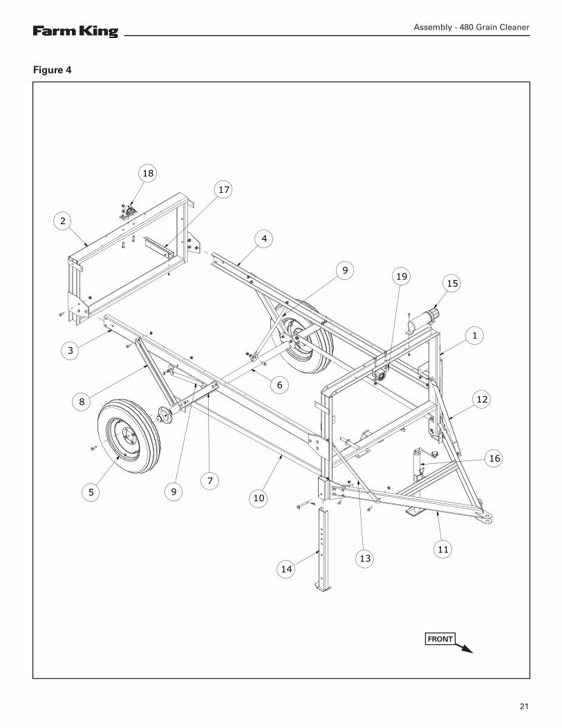
General Parts InformationThe parts identification section list descriptions, part numbers and quantities for all North America Base Model 480 Grain Cleaners. Contact your Farm King dealer for additional parts information.
Frame Assembly
12
36723
53
11
53
16
17
18
14
13
19
2210
27
12
21
20
5 3
5 3
24
25
9
15
4 2
28
26
8
3 6 5
5 6 3
930510

Parts Identification - 480 Grain Cleaner
43
ITEM PART NUMBER DESCRIPTION QTY.
1 812026 5/16" X 1" HEX BOLT (PL) 2
2 812362 5/16" LOCK NUT (PL) 4
3 812364 1/2" LOCK NUT (PL) 48
4 81549 5/16" X 3/4" HEX BOLT (PL) 2
5 81620 1/2" X 1 1/4" HEX BOLT PL 44
6 84048 1/2" SAE FLAT WASHER (PL) 12
7 87553 1/2" X 1.75" HEX BOLT UNC GR5 (PL) 4
8 900266 AXLE ASSY GC 1
9 909277 MANUAL HOLDER 3 1/2" X 12" 1
10 961012 #16 HAIR PIN CLIP 2
11 968404 WHEEL BOLT 1/2" X 1 1/4" (PL) 8
12 973202 REAR FRAME WELDT 1
13 973203 FRAME SIDE - RIGHT HAND 1
14 973204 FRAME SIDE - LEFT HAND 1
15 973205 HTCH WELDT 1
16 973207 REAR AXLE BRACE 2
17 973208 AXLE BRACE 10GA X 5" X 26" 2
18 973209 AXLE BRACE 11GA X 01.250" X 25" 2
19 973210L FRAME BRACE 2
20 973211 HTCH BRACE - RH 1
21 973212 HTCH BRACE - LH 1
22 973214 FRONT LEG PIN WELDMENT 2
23 973223 1 1/4" PILLOW BRG W/ COLLAR 2
24 973269 FRT FRAME WELDT 1
25 F3260 JACK SB & GC 1
26 F7110 WHEEL-15" X 4.5" X 4 BOLT 2
27 SZ000472 FRONT LEG ASSY 2
28 SZ000490 BRKT - TRASH DSCHG CHUTE MOUNTING 1

Parts Identification - 480 Grain Cleaner
44
Guard Assembly
24
26
27
21
21
25
28
671
4510
16
18 11 7 2
14
11 2
19
20
13 22
1523 11 7 2
1 7 6
83
2 11
12 17 9
10 5 4
4 10
930520
Parts Identification - 480 Grain Cleaner
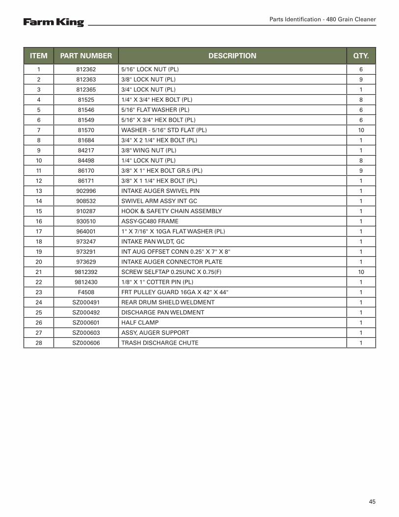
45
ITEM PART NUMBER DESCRIPTION QTY.
1 812362 5/16" LOCK NUT (PL) 6
2 812363 3/8" LOCK NUT (PL) 9
3 812365 3/4" LOCK NUT (PL) 1
4 81525 1/4" X 3/4" HEX BOLT (PL) 8
5 81546 5/16" FLAT WASHER (PL) 6
6 81549 5/16" X 3/4" HEX BOLT (PL) 6
7 81570 WASHER - 5/16" STD FLAT (PL) 10
8 81684 3/4" X 2 1/4" HEX BOLT (PL) 1
9 84217 3/8" WING NUT (PL) 1
10 84498 1/4" LOCK NUT (PL) 8
11 86170 3/8" X 1" HEX BOLT GR.5 (PL) 9
12 86171 3/8" X 1 1/4" HEX BOLT (PL) 1
13 902996 INTAKE AUGER SWIVEL PIN 1
14 908532 SWIVEL ARM ASSY INT GC 1
15 910287 HOOK & SAFETY CHAIN ASSEMBLY 1
16 930510 ASSY-GC480 FRAME 1
17 964001 1" X 7/16" X 10GA FLAT WASHER (PL) 1
18 973247 INTAKE PAN WLDT, GC 1
19 973291 INT AUG OFFSET CONN 0.25" X 7" X 8" 1
20 973629 INTAKE AUGER CONNECTOR PLATE 1
21 9812392 SCREW SELFTAP 0.25UNC X 0.75(F) 10
22 9812430 1/8" X 1" COTTER PIN (PL) 1
23 F4508 FRT PULLEY GUARD 16GA X 42" X 44" 1
24 SZ000491 REAR DRUM SHIELD WELDMENT 1
25 SZ000492 DISCHARGE PAN WELDMENT 1
26 SZ000601 HALF CLAMP 1
27 SZ000603 ASSY, AUGER SUPPORT 1
28 SZ000606 TRASH DISCHARGE CHUTE 1

Parts Identification - 480 Grain Cleaner
46
Pulley Assembly
13
12
26
20
2 10
9 5 2
17
16
18
24
1183
2114
67234
1
28
22
1526
13
27
25
19
930520

Parts Identification - 480 Grain Cleaner
47
ITEM PART NUMBER DESCRIPTION QTY.
1 81210 1/4" X 2" COTTER PIN (PL) 1
2 812363 3/8" LOCK NUT (PL) 8
3 812364 1/2" LOCK NUT (PL) 4
4 812482 5/8" LOCK NUT (PL) 1
5 81570 WASHER - 5/16" STD FLAT (PL) 8
6 81671 5/8" X 4" HEX BOLT (PL) 1
7 81678 5/8" FLAT WASHER STD (PL) 3
8 84048 1/2" SAE FLAT WASHER (PL) 4
9 86170 3/8" X 1" HEX BOLT GR.5 (PL) 4
10 86171 3/8" X 1 1/4" HEX BOLT (PL) 4
11 87553 1/2" X 1.75" HEX BOLT UNC GR5 (PL) 4
12 900286 KEY PULLEY, 0.25" SQ X 2.50" GC 1
13 901550 KEY 2
14 961792 HOUSING W/BEARING PILLOW (P205) 2
15 973240 REDUCER SHFT 01" X 14 1/2" 1
16 973241 MOTOR MOUNT 0.188" X 9.5" X 18" 1
17 973242 MM GUARD 16GA X 10" X 22" 1
18 973243 MM CLAMP 0.313" X 1.5" X 6.875" 2
19 973245 REDUCER SHFT BUSH 1.250"OD X W 11GA 1
20 973248 B-87 BELT 2
21 973287 12" DBL SHEAVE 1
22 973618 BELT TIGHTENER SPRING 2
23 973645 IDLER PULLEY 2
24 9812380 1/2" X 4" SQ. HD. SET SCREW (PL) 1
25 985639 03/8" X 1/2" SOCKET SET SCREW (BR) 2
26 967141 SETSCREW SCKTCUP .313NC X 025BR 4
27 SZ000614 3" DOUBLE PULLEY 1
28 SZ001250 IDLER ARM PLATE, 2016 & UP 2

Parts Identification - 480 Grain Cleaner
48
Trash Pan Assembly (GC482 Option)
15
11
17
12
13
7
9
18
1 4 5
14
10
19
7
16
236
236
930513

Parts Identification - 480 Grain Cleaner
49
ITEM PART NUMBER DESCRIPTION QTY.
1 812482 5/8" LOCK NUT (PL) 1
2 81525 1/4" X 3/4" HEX BOLT (PL) 48
3 81546 5/16" FLAT WASHER (PL) 48
4 81678 5/8" FLAT WASHER STD (PL) 8
5 84289 5/8" X 3" HEX BOLT GR.5 (PL) 1
6 84498 1/4" LOCK NUT (PL) 48
7 901550 KEY 2
8 963153 CTN 8 X 15 X 10.5 WAX 1
9 967141 5/16" X 1/4" SOCKET SET SCREW (BR) 2
10 968892 PULLEY BELT TGHNR 1
11 973253 TRASH PAN SIDE PANEL (OPT) 16GA X 19" X 105" 2
12 973254 TRASH PAN SIDE (OPTION) 16GA X 28" X 92" 2
13 973255 TRASH PAN END (OPT) 2
14 973259 B-37 V-BELT 1
15 9812392 SCREW SELFTAP 0.25UNC X 0.75(F) 20
16 967141 SETSCREW SCKTCUP .313NC X 025BR 2
17 F4522 TRASH PAN TROUGH BUNDLE (OPT) 1
18 SZ000613 SINGLE SHEAVE 6" 1
19 SZ000615 3" SINGLE SHEAVE 1

Parts Identification - 480 Grain Cleaner
50
Drum And Screen Assembly
32
10
11
9
8
32
22
12
13
16
15
14
15
7
21
244
244
930511

Parts Identification - 480 Grain Cleaner
51
ITEM PART NUMBER DESCRIPTION QTY.
1 812037 Ø3/8" X 3/4" SQHDCUP SETSCREW (PL) 4
2 812362 5/16" LOCK NUT (PL) 66
3 812626 BOLT CARR 0.313NC X 1.00GR5PL 66
4 81546 5/16" FLAT WASHER (PL) 72
5 81592 3/8" HEX NUT (PL) 4
6 84498 1/4" LOCK NUT (PL) 7
7 930523 ASSY-CONE EXTENSION TUBE 1
8 973215 FRT DRUM RING WELDT 1
9 973216 WELDT - CENTERR DRUM RING 1
10 973217 REAR CENTER DRUM RING (#480 GC) 1
11 973218 REAR DRUM RING WELDT 1
12 973220 OUTER DRUM SCREEN SUPPORT 0.25" X 1 1/2" X 96" 4
13 973221 CONE SCREEN SUP 0.25" X 1.25" X 62.75" 6
14 973222 DRUM SHFT WELDT 1
15 973224 CONE SCREEN SUP RING 1
16 973225 CONE FLOW CTRL WELDT 1
17 973226 DRUM STRAP 148.25" 480 GC 4
18 973227 CONE STRAP 92-1/4" (#480 GC) 1
19 973228 CONE STRAP- 82" (#480 GC) 1
20 973229 CONE STRAP - 73 1/2" (#480 GC) 1
21 973270 B-164 V-BELT 2
22 973288 OUTER DRUM SCREEN SUPPORT 0.25"X1.5"X96" 4
23 973289 SPRING, SCREEN (GRAIN CLEANER) 2
24 9812392 SCREW SELFTAP 0.25UNC X 0.75(F) 72
25 9812398 BOLT STOVE 0.25 UNC X 2.50 RDHD 7
- 903522 5 X 5 CONE SCREEN 3
- 973238 4 X 4 CONE SCREEN 3
- 973237 3 X 3 CONE SCREEN 3
- 924032 2 X 2 CONE SCREEN 3
- 973236 5/8 X 5/8 CONE SCREEN 3
- 911904 10 X 10 DRUM SCREEN 3
- 911902 8 X 8 DRUM SCREEN 3
- 911901 6 X 6 DRUM SCREEN 3
- 911903 5 X 5 DRUM SCREEN 3
- 911900 4 X 4 DRUM SCREEN 3

Parts Identification - 480 Grain Cleaner
52
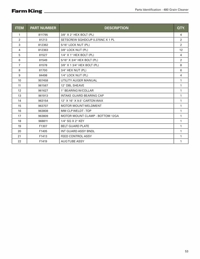
Utility Auger Assembly
22
21
20
4 7
36
13
16
4 1
17
19
211
8 15
9 5
18
12
930512
Parts Identification - 480 Grain Cleaner
53
ITEM PART NUMBER DESCRIPTION QTY.
1 811795 3/8" X 2" HEX BOLT (PL) 4
2 81213 SETSCREW SQHDCUP 0.375NC X 1 PL 2
3 812362 5/16" LOCK NUT (PL) 2
4 812363 3/8" LOCK NUT (PL) 12
5 81527 1/4" X 1" HEX BOLT (PL) 4
6 81549 5/16" X 3/4" HEX BOLT (PL) 2
7 81578 3/8" X 1 3/4" HEX BOLT (PL) 8
8 81700 3/4" HEX NUT (PL) 6
9 84498 1/4" LOCK NUT (PL) 4
10 907458 UTILITY AUGER MANUAL 1
11 961567 12" DBL SHEAVE 1
12 961627 1" BEARING W/COLLAR 1
13 961913 INTAKE GUARD BEARING CAP 1
14 963154 12" X 16" X 9.5" CARTON WAX 1
15 963707 MOTOR MOUNT WELDMENT 1
16 963808 MM CLP WELDT - TOP 1
17 963809 MOTOR MOUNT CLAMP - BOTTOM 12GA 1
18 968811 1/4" SQ X 2" KEY 1
19 F1307 BELT GUARD PLATE 1
20 F1405 INT GUARD ASSY BNDL 1
21 F1413 FEED CONTROL ASSY 1
22 F1419 AUG TUBE ASSY 1

Parts Identification - 480 Grain Cleaner
54

Specifications And Shipping Kit Numbers - 480 Grain Cleaner
55
Specifications And Shipping Kit Numbers
Specifications 57
Shipping Kit And Bundle Numbers 57
Hardware Torque Values 58
Metric Chart 58
Imperial Chart 59

Specifications And Shipping Kit Numbers - 480 Grain Cleaner
56

Specifications And Shipping Kit Numbers - 480 Grain Cleaner
57
Specifications
Model GC360
Height 78.6” (1996.4 mm)
Width 76.1” (1932.9 mm)
Length 176.7” (4488.2 mm)
Motor 3 HP
Note: Dimensions are approximate measurements.
Shipping Kit And Bundle NumbersThe following is a list of Kit Numbers for this product and the Bundle Numbers, Descriptions, and Quantities for each Kit.
Qty. Bundle Description
GC480 GRAIN CLEANER W/ HITCH, TIRES, TILT ADJ.
1 Y480 480 GRAIN CLEANER
GC482 GRAIN CLEANER W/ HITCH, TIRES, TILT ADJ., SHROUD AND FINES AUGER
1 Y482 482 GRAIN CLEANER
OPTIONAL EQUIPMENT
1 Y811S8” X 11' UTILITY AUGER W/FLOW CONTROL AND BOLT-ON SPOUT
1 F211 BIG DADDY HOPPER
1 F210 STANDARD FLEX HOPPER
SCREEN KITS
1 F4519 10 x 10 DRUM SCREEN (3)
1 F4518 8 x 8 DRUM SCREEN (3)
1 F4517 6 x 6 DRUM SCREEN (3)
1 F4516 5 x 5 DRUM SCREEN (3)
1 F4515 4 x 4 DRUM SCREEN (3)
1 F4319 5 x 5 CONE SCREEN (3)
1 F4514 4 x 4 CONE SCREEN (3)
1 F4513 3 x 3 CONE SCREEN (3)
1 F4511 2 x 2 CONE SCREEN (3)
1 F4512 5/8 x 5/8 CONE SCREEN (3)

Specifications And Shipping Kit Numbers - 480 Grain Cleaner
58
Hardware Torque ValuesMetric Chart

Specifications And Shipping Kit Numbers - 480 Grain Cleaner
59
Imperial Chart

Specifications And Shipping Kit Numbers - 480 Grain Cleaner
60

Warranty - 480 Grain Cleaner
61
Warranty
Farm King Base Limited Warranty 63
Repair Parts Limited Warranty 63
What Is Not Covered 63
Authorized Dealer And Labor Costs 63
Warranty Requirements 64
EXCLUSIVE EFFECT OF WARRANTY AND LIMITATION OF LIABILITY 64

Warranty - 480 Grain Cleaner
62

Warranty - 480 Grain Cleaner
63
Farm King Base Limited WarrantyFarm King provides this warranty only to original retail purchasers of its products. Farm King warrants to such purchasers that all Farm King manufactured parts and components used and serviced as provided for in the Operator’s Manual shall be free from defects in materials and workmanship for a period following delivery to the original retail purchaser of one (1) year. This limited warranty applies only to those parts and components manufactured by Farm King. Parts and components manufactured by others are subject to their manufacturer’s warranties, if any.
Farm King will fulfill this limited warranty by, at its option, repairing or replacing any covered part that is defective or is the result of improper workmanship, provided that the part is returned to Farm King within thirty (30) days of the date that such defect or improper workmanship is, or should have been, discovered. Parts must be returned through the selling representative and the buyer must prepay transportation charges.
Farm King will not be responsible for repairs or replacements that are necessitated, in whole or part, by the use of parts not manufactured by or obtained from Farm King. Under no circumstances are component parts warranted against normal wear and tear. There is no warranty on product pump seals, product pump bearings, rubber product hoses, pressure gauges, or other components that require replacement as part of normal maintenance.
Repair Parts Limited Warranty
Farm King warrants genuine Farm King replacement parts purchased after the expiration of the Farm King Limited Warranty, and used and serviced as provided for in the Operator’s Manual, to be free from defects in materials or workmanship for a period of thirty (30) days from the invoice date for the parts. Farm King will fulfill this limited warranty by, at its option, repairing or replacing any covered part that is defective or is the result of improper workmanship, provided that the part is returned to Farm King within thirty (30) days of the date that such defect or improper workmanship is, or should have been, discovered. Such parts must be shipped to the Farm King factory at the purchaser’s expense.
What Is Not Covered
Under no circumstances does this limited warranty cover any components or parts that have been subject to the following: negligence; alteration or modification not approved by Farm King; misuse; improper storage; lack of reasonable and proper maintenance, service, or repair; normal wear; damage from failure to follow operating instructions; accident; and/or repairs that have been made with parts other than those manufactured, supplied, and or authorized by Farm King.
Authorized Dealer And Labor Costs
Repairs eligible for labor under this limited warranty must be made by Farm King or an authorized Farm King dealer. Farm King retains the exclusive discretion to determine whether it will pay labor costs for warranty repairs or replacements, and the amount of such costs that it will pay and the time in which the repairs will be made. If Farm King determines that it will pay labor costs for warranty work, it will do so by issuing a credit to the dealer’s or distributor’s account. Farm King will not approve or pay invoices sent for repairs that Farm King has not previously approved. Warranty service does not extend the original term of this limited warranty.

Warranty - 480 Grain Cleaner
64
Warranty Requirements
To be covered by warranty, each new product must be registered with Farm King within thirty (30) days of delivery to original retail purchaser. If the customer decides to purchase replacement components before the warranty disposition of such components is determined, Farm King will bill the customer for such components and then credit the replacement invoice for those components later determined to be covered by this limited warranty. Any such replacement components that are determined not be covered by this limited warranty will be subject to the terms of the invoice and shall be paid for by the purchaser.
EXCLUSIVE EFFECT OF WARRANTY AND LIMITATION OF LIABILITY
TO THE EXTENT PERMITTED BY LAW, FARM KING DISCLAIMS ANY WARRANTIES, REPRESENTATIONS, OR PROMISES, EXPRESS OR IMPLIED, AS TO THE QUALITY, PERFORMANCE, OR FREEDOM FROM DEFECT OF THE COMPONENTS AND PARTS COVERED BY THIS WARRANTY AND NOT SPECIFICALLY PROVIDED FOR HEREIN.
TO THE EXTENT PERMITTED BY LAW, FARM KING DISCLAIMS ANY IMPLIED WARRANTIES OF MERCHANTABILITY AND FITNESS FOR A PARTICULAR PURPOSE ON ITS PRODUCTS COVERED HEREIN, AND DISCLAIMS ANY RELIANCE BY THE PURCHASER ON FARM KING’S SKILL OR JUDGMENT TO SELECT OR FURNISH GOODS FOR ANY PARTICULAR PURPOSE. THE PURCHASER’S ONLY AND EXCLUSIVE REMEDIES IN CONNECTION WITH THE BREACH OR PERFORMANCE OF ANY WARRANTY ON FARM KING’S PRODUCTS ARE THOSE SET FORTH HEREIN. IN NO EVENT SHALL FARM KING BE LIABLE FOR INCIDENTAL OR CONSEQUENTIAL DAMAGES (INCLUDING, BY WAY OF EXAMPLE ONLY AND NOT LIMITATION, LOSS OF CROPS, LOSS OF PROFITS OR REVENUE, OTHER COMMERCIAL LOSSES, INCONVENIENCE, OR COST OF REPLACEMENT OF RENTAL EQUIPMENT). IN NO EVENT SHALL FARM KING’S CONTRACT OR WARRANTY LIABILITY EXCEED THE PURCHASE PRICE OF THE PRODUCT. (Note that some states do not allow limitations on how long an implied warranty lasts or the exclusion or limitation of incidental or consequential damages, so the above limitations and exclusion may not apply to you.) This warranty gives you specific legal rights and you may also have other rights, which vary from state to state.
Farm King neither assumes nor authorizes any person or entity, including its selling representatives, to assume any other obligations or liability in connections with the sale of covered equipment, or to make any other warranties, representations, or promises, express or implied, as to the quality, performance, or freedom from defect of the components and parts covered herein. No one is authorized to alter, modify, or enlarge this limited warranty, or its exclusions, limitations and reservations.
Corrections of defects and improper workmanship in the manner, and for the applicable time periods, provided for herein shall constitute fulfillment of all responsibilities of Farm King to the purchaser, and Farm King shall not be liable in negligence, contract, or on any other basis with respect to the subject equipment.
This limited warranty is subject to any existing conditions of supply which may directly affect Farm King’s ability to obtain materials or manufacturer replacement parts.
Buhler Industries Inc. reserves the right to make improvements in design or changes in specifications to its products at anytime, without incurring any obligation to owners of units previously sold.


www.farm-king.com
a division of Buhler Industries Inc.
1330 43rd Street NorthFargo, ND, 58102Toll Free: 887.447.6008E-mail: [email protected]
Equipment shown is subject to change without notice. ©2017 Buhler Trading Inc. Printed in USA TSX:BUI