Embed Size (px)
Citation preview
DD150-U
Operating instructions enMode d’emploi frManual de instrucciones esManual de instruções pt

1
This Product is CertifiedCe produit est certifié
Este producto esta certificadoEste produto está certificado
C US

2
3
4 5

6
8
9 10
11 12
7

16
17 18
19 20
14
15
13

21 22
23 24
25 26
ORIGINAL OPERATING INSTRUCTIONS
DD 150 U diamond coring system
It is essential that the operating instruc-tions are read before the machine is oper-ated for the first time.
Always keep these operating instructionstogether with the machine.
Ensure that the operating instructions arewith the machine when it is given to otherpersons.
Contents Page1. General information 22. Description 33. Accessories 64. Technical data 75. Safety instructions 76. Before use 107. Operation 148. Care and maintenance 209. Troubleshooting 21
10. Disposal 2311. Manufacturer’s warranty 24
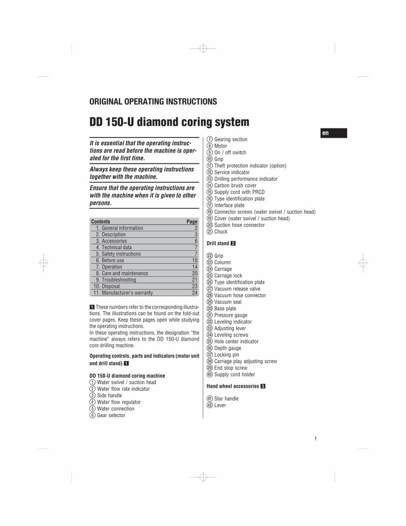
1 These numbers refer to the corresponding illustra-tions. The illustrations can be found on the fold-outcover pages. Keep these pages open while studyingthe operating instructions.In these operating instructions, the designation “themachine” always refers to the DD 150-U diamondcore drilling machine.
Operating controls, parts and indicators (motor unitand drill stand) 1
DD 150 U diamond coring machine@
Water swivel / suction head;
Water flow rate indicator=
Side handle%
Water flow regulator&
Water connection(
Gear selector
)Gearing section
+Motor
§On / off switch
/Grip
:Theft protection indicator (option)
·Service indicator
$Drilling performance indicator
£Carbon brush cover
|Supply cord with PRCD
¡Type identification plate
QInterface plate
WConnector screws (water swivel / suction head)
ECover (water swivel / suction head)
RSuction hose connector
TChuck
Drill stand 2
ZGrip
UColumn
ICarriage
OCarriage lock
PType identification plate
ÜVacuum release valve
[Vacuum hose connector
]Vacuum seal
ÆBase plate
ºPressure gauge
•Leveling indicator
AAdjusting lever
SLeveling screws
DHole center indicator
FDepth gauge
GLocking pin
HCarriage play adjusting screw
JEnd stop screw
KSupply cord holder
Hand wheel accessories 3
LStar handle
ÖLever
en
1
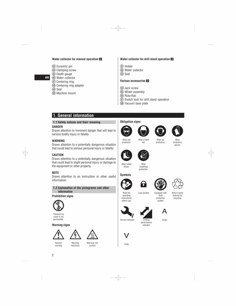
Water collector for manual operation 3
ÄEccentric pin
†Clamping screw
ŒDepth gauge
ÅWater collector
ªCentering ring
^Centering ring adapter
YSeal
XMachine mount
Water collector for drill stand operation 3
CHolder
VWater collector
BSeal
Various accessories 3
NJack screw
MWheel assembly
?Rota-Rail
!Switch lock for drill stand operation
—Vacuum base plate
1. General information1.1 Safety notices and their meaning
DANGERDraws attention to imminent danger that will lead toserious bodily injury or fatality.
WARNINGDraws attention to a potentially dangerous situationthat could lead to serious personal injury or fatality.
CAUTIONDraws attention to a potentially dangerous situationthat could lead to slight personal injury or damage tothe equipment or other property.
NOTEDraws attention to an instruction or other usefulinformation.
1.2 Explanation of the pictograms and otherinformation
Prohibition signs
Transport bycrane is notpermissible.
Warning signs
Generalwarning
Warning:electricity
Warning: hotsurface
Obligation signs
Wear eyeprotection.
Wear a hardhat.
Wear earprotection.
Wearprotective
gloves.
Wear safetyshoes.
Wearbreathing
protection.
Symbols
Read theoperating
instructionsbefore use.
Lock symbol Equipped withtheft
protectionsystem
Return wastematerial forrecycling.
Service indicator Drillingperformance
indicator
Amps
Volts
en
2

RPM
VACUUM
VACUUM
Alternatingcurrent
Watts Hertz Nominal speedunder no load
Diameter Millimeters Revolutions perminute
Revolutionsper minute
On the drill stand and the vacuum base plate
Upper: An additional means of securing the drill standmust be employed when the machine is used forhorizontal drilling with the vacuum securing method.
Lower: Use of the vacuum securing method for over-head drilling with the drill stand is not permissible.
On the machine
Use of the water collection system in conjunction witha wet-type industrial vacuum cleaner is a mandatoryrequirement for working on ceilings.
Location of identification data on the machineThe type designation and serial number can be foundon the type identification plate on the machine. Makea note of this data in your operating instructions andalways refer to it when making an enquiry to yourHilti representative or service department.
Type:
Generation: 01
Serial no.:
2. Description2.1 Use of the product as directed
The DD 150-U is an electrically powered diamond core drilling machine for hand-guided wet and dry drillingof through holes or blind holes (e.g. anchor holes) and for wet drilling of through holes or blind holes in(reinforced) mineral materials with the machine mounted on a drill stand.When mounted on the drill stand, the system must be adequately secured to the working surface with ananchor or vacuum base plate before use.Drilling into materials that produce electrically conductive dust (e.g. magnesium) is not permissible.Where possible, use a suitable industrial vacuum cleaner when working with the system, e.g. the HiltiVC 20 U/UM, VC 40 U/UM or VC 60 U.
en
3

To avoid injury, use only genuine Hilti core bits and DD 150-U accessories.Observe the safety rules and operating instructions for the accessories used.Observe the information printed in the operating instructions concerning operation, care and maintenance.Nationally applicable industrial safety regulations must be observed.The machine, accessories and cutting tools may present hazards when handled incorrectly by untrainedpersonnel or when used not as directed.Use of the water collection system in conjunction with a wet-type industrial vacuum cleaner is a mandatoryrequirement for wet drilling overhead.Use of the vacuum fastening method for overhead drilling is prohibited.An additional means of securing the drill stand must be employed when the machine is secured with thevacuum base plate (accessory) for horizontal drilling.Do not strike the base plate with a hammer or other heavy object when making adjustments to it.Tampering with or modification of the machine, drill stand and accessories is strictly prohibited.
WARNINGThe machine may be operated only when connected to an adequately-rated electric supply equipped withan earth (ground) conductor.
WARNINGDrilling into materials hazardous to the health (e.g. asbestos) is not permissible.
DANGERUse only the genuine Hilti accessories or ancillary equipment listed in the operating instructions. Use ofaccessories or ancillary equipment not listed in the operating instructions may present a risk of personal injury.
2.2 Use of the machine with various items of equipment
With / without the drill stand With / without thesystem Core bit diameter Drilling direction
Hand-guided / dry With dust removalsystem
37…162 mm(1½"...6¼")
All directions
Hand-guided / wet Without water collec-tion system
8…132 mm (½"...5") Not upwards
Hand-guided / wet With water collectionsystem
8…62 mm (½"...2½") All directions
On drill stand / wet Without water collec-tion system
12…162 mm(½...6¼")
Not upwards
On drill stand / wet With water collectionsystem
12…162 mm(½...6¼")
All directions
2.3 Gears and corresponding core bit diametersOn drill stand, wet
Gear Core bit diameters(mm)
Core bit diameters(inches)
Speed under no load/min
1 102…162 4…6 7802 28…87 1 …3 1,5203 12…25 …1 2,850
en
4

Hand-guided, wet
Gear Core bit diameters(mm)
Core bit diameters(inches)
Speed under no load/min
1 121…131 4 …5 7802 41…111 1 …4 1,5203 8…36 …1 2,850
Hand-guided, dry, HDM
Gear Core bit diameters(mm)
Core bit diameters(inches)
Speed under no load/min
1 122…162 4 …6 7802 67…112 2 …4 1,5203 37…62 1 …2 2,850
Hand-guided, dry, PCM
Gear Core bit diameters(mm)
Core bit diameters(inches)
Speed under no load/min
1 52…162 2…6 780
2.4 Status indicator
LED indicators State Description / informationTheft protection indicator (11) Blinking yellow light The machine's theft protection sys-
tem is active and must be unlockedwith the TPS key.
Service indicator (12) Red light and the machinestarts
The carbon brushes are badly worn.After the lamp lights for the first time,the machine may continue to be usedfor several hours before the auto-matic cut-out is activated. Have thecarbon brushes changed in good timeso that the machine is always readyfor use.
Red light and the machinedoesn’t start
The carbon brushes must bechanged.
Blinking red light Temporary fault, see Troubleshootingsection.
Drilling performance indicator (13)(only in conjunction with the drillstand)
Orange light Contact pressure too lowGreen light Optimum contact pressureRed light Contact pressure too high
NOTEWhen using the machine for hand-guided coring, the drilling performance indicator gives no indication of theoptimum pressure.
2.5 TPS theft protection system (optional)The machine may be optionally equipped with the TPS theft protection system. If equipped with this feature,the machine can be unlocked and made ready for operation only through use of the corresponding TPS key.
en
5
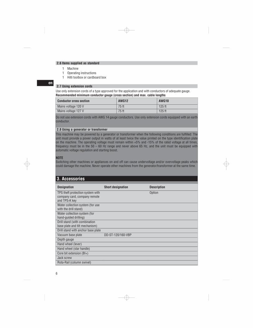
2.6 Items supplied as standard
1 Machine1 Operating instructions1 Hilti toolbox or cardboard box
2.7 Using extension cordsUse only extension cords of a type approved for the application and with conductors of adequate gauge.Recommended minimum conductor gauge (cross section) and max. cable lengths
Conductor cross section AWG12 AWG10
Mains voltage 120 V 75 ft 125 ftMains voltage 127 V 75 ft 125 ft
Do not use extension cords with AWG 14 gauge conductors. Use only extension cords equipped with an earthconductor.
2.8 Using a generator or transformerThis machine may be powered by a generator or transformer when the following conditions are fulfilled: Theunit must provide a power output in watts of at least twice the value printed on the type identification plateon the machine. The operating voltage must remain within +5% and -15% of the rated voltage at all times,frequency must be in the 50 – 60 Hz range and never above 65 Hz, and the unit must be equipped withautomatic voltage regulation and starting boost.
NOTESwitching other machines or appliances on and off can cause undervoltage and/or overvoltage peaks whichcould damage the machine. Never operate other machines from the generator/transformer at the same time.
3. Accessories
Designation Short designation Description
TPS theft protection system withcompany card, company remoteand TPS K key
Option
Water collection system (for usewith the drill stand)Water collection system (forhand-guided drilling)Drill stand (with combinationbase plate and tilt mechanism)Drill stand with anchor base plateVacuum base plate DD-ST-120/160-VBPDepth gaugeHand wheel (lever)Hand wheel (star handle)Core bit extension (BI+)Jack screwRota-Rail (column swivel)
en
6
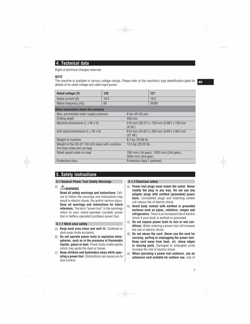
4. Technical dataRight of technical changes reserved.
NOTEThe machine is available in various voltage ratings. Please refer to the machine’s type identification plate fordetails of its rated voltage and rated input power.
Rated voltage [V] 120 127
Rated current [A] 19.5 18.5Mains frequency [Hz] 60 50/60
Other information about the machineMax. permissible water supply pressure 6 bar (87.02 psi)Drilling depth 450 mmMachine dimensions (L x W x H) 516 mm (20.31") x 129 mm (5.08") x 159 mm
(6.26")Drill stand dimensions (L x W x H) 610 mm (24.02") x 250 mm (9.84") x 952 mm
(37.48")Weight of machine 8.2 kg (18.08 lb)Weight of the DD-ST 150 drill stand with combina-tion base plate and carriage
13.3 kg (29.32 lb)
Rated speed under no load 780 /min (1st gear), 1520 /min (2nd gear),2850 /min (3rd gear)
Protection class Protection class I (earthed)
5. Safety instructions5.1 General Power Tool Safety Warnings
a)WARNING
Read all safety warnings and instructions. Fail-ure to follow the warnings and instructions mayresult in electric shock, fire and/or serious injury.Save all warnings and instructions for futurereference. The term “power tool” in the warningsrefers to your mains-operated (corded) powertool or battery-operated (cordless) power tool.
5.1.1 Work area safetya) Keep work area clean and well lit. Cluttered or
dark areas invite accidents.b) Do not operate power tools in explosive atmo-
spheres, such as in the presence of flammableliquids, gases or dust. Power tools create sparkswhich may ignite the dust or fumes.
c) Keep children and bystanders away while oper-ating a power tool. Distractions can cause you tolose control.
5.1.2 Electrical safetya) Power tool plugs must match the outlet. Never
modify the plug in any way. Do not use anyadapter plugs with earthed (grounded) powertools. Unmodified plugs and matching outletswill reduce risk of electric shock.
b) Avoid body contact with earthed or groundedsurfaces such as pipes, radiators, ranges andrefrigerators. There is an increased risk of electricshock if your body is earthed or grounded.
c) Do not expose power tools to rain or wet con-ditions. Water entering a power tool will increasethe risk of electric shock.
d) Do not abuse the cord. Never use the cord forcarrying, pulling or unplugging the power tool.Keep cord away from heat, oil, sharp edgesor moving parts. Damaged or entangled cordsincrease the risk of electric shock.
e) When operating a power tool outdoors, use anextension cord suitable for outdoor use. Use of
en
7

a cord suitable for outdoor use reduces the riskof electric shock.
f) If operating a power tool in a damp locationis unavoidable, use a residual current device(RCD) protected supply. Use of an RCD reducesthe risk of electric shock.
5.1.3 Personal safetya) Stay alert, watch what you are doing and use
common sense when operating a power tool. Donot use a power tool while you are tired or underthe influence of drugs, alcohol or medication.A moment of inattention while operating powertools may result in serious personal injury.
b) Use personal protective equipment. Alwayswear eye protection. Protective equipmentsuch as dust mask, non-skid safety shoes, hardhat, or hearing protection used for appropriateconditions will reduce personal injuries.
c) Prevent unintentional starting. Ensure theswitch is in the off position before connectingto power source and/or battery pack, picking upor carrying the tool. Carrying power tools withyour finger on the switch or energising powertools that have the switch on invites accidents.
d) Remove any adjusting key or wrench beforeturning the power tool on. A wrench or a key leftattached to a rotating part of the power tool mayresult in personal injury.
e) Do not overreach. Keep proper footing and bal-ance at all times. This enables better control ofthe power tool in unexpected situations.
f) Dress properly. Do not wear loose clothing orjewellery. Keep your hair, clothing and glovesaway from moving parts. Loose clothes, jewelleryor long hair can be caught in moving parts.
g) If devices are provided for the connection ofdust extraction and collection facilities, ensurethese are connected and properly used. Use ofdust collection can reduce dust-related hazards.
5.1.4 Power tool use and carea) Do not force the power tool. Use the correct
power tool for your application. The correctpower tool will do the job better and safer at therate for which it was designed.
b) Do not use the power tool if the switch does notturn it on and off. Any power tool that cannot becontrolled with the switch is dangerous and mustbe repaired.
c) Disconnect the plug from the power sourceand/or the battery pack from the power toolbefore making any adjustments, changing ac-cessories, or storing power tools. Such preven-tive safety measures reduce the risk of startingthe power tool accidentally.
d) Store idle power tools out of the reach of chil-dren and do not allow persons unfamiliar withthe power tool or these instructions to operatethe power tool. Power tools are dangerous in thehands of untrained users.
e) Maintain power tools. Check for misalignmentor binding of moving parts, breakage of partsand any other condition that may affect thepower tool’s operation. If damaged, have thepower tool repaired before use. Many accidentsare caused by poorly maintained power tools.
f) Keep cutting tools sharp and clean. Properlymaintained cutting tools with sharp cutting edgesare less likely to bind and are easier to control.
g) Use the power tool, accessories and tool bitsetc. in accordance with these instructions takinginto account the working conditions and thework to be performed. Use of the power tool foroperations different from those intended couldresult in a hazardous situation.
5.1.5 Servicea) Have your power tool serviced by a qualified
repair person using only identical replacementparts. This will ensure that the safety of the powertool is maintained.
5.2 Drill safety warningsa) Wear ear protectors when impact drilling. Ex-
posure to noise can cause hearing loss.b) Use auxiliary handle(s), if supplied with the
tool. Loss of control can cause personal injury.c) Hold power tool by insulated gripping surfaces,
when performing an operation where the cuttingaccessory may contact hidden wiring or its owncord. Cutting accessory contacting a "live" wiremay make exposed metal parts of the power tool"live" and could give the operator an electric shock.
en
8
5.3 Additional safety rules
5.3.1 Personal safety
a) During hand-held use, always hold the machinesecurely with both hands on the grips provided.Keep the grips dry, clean and free from oil andgrease.
b) Check that the side handle is tightened securely.c) Assemble the parts of the mounting device cor-
rectly before attaching the machine. In order toavoid the risk of collapse, it is important that theparts are assembled correctly.
d) Attach the machine to the mounting device se-curely before beginning use. Movement of themachine on the mounting device could lead toloss of control.
e) Place the mounting device on a solid, flat andlevel surface. If the mounting device can slip orwobble, the machine cannot be guided smoothlyand safely.
f) Check the nature of the surface. Rough surfacesmay reduce holding power. Coatings or compositematerials may pull away from the surface whileyou are working.
g) Do not overload the mounting device and do notuse it as a substitute for a ladder or platform.Overloading the mounting device or standing on itmay shift its center of gravity to a higher position,causing it to tip over.
h) Respiratory protection must be worn if the ma-chine is used without a dust extraction systemfor work that creates dust.
i) Improve the blood circulation in your fingers byrelaxing your hands and exercising your fingersduring breaks between working.
j) Avoid touching rotating parts. Switch the powertool on only after bringing it into position at theworkpiece. Touching rotating parts, especiallyrotating drill bits, discs or blades, etc. may leadto injury.
k) When using the equipment, always lead thesupply cord, the extension cord and the waterhose (if applicable) away from the machine tothe rear. This will reduce the risk of tripping andfalling over the cord or hose while working.
l) Avoid skin contact with drilling slurry.
m) Wear protective gloves when changing corebits. The core bit may become hot during use.
n) Children must be instructed not to play with themachine.
o) The machine is not intended for use by chil-dren, by debilitated persons or those who havereceived no instruction or training.
p) WARNING: Some dust created by grinding,sanding, cutting and drilling contains chem-icals known to cause cancer, birth defects,infertility or other reproductive harm; or seri-ous and permanent respiratory or other injury.Some examples of these chemicals are: lead fromlead-based paints, crystalline silica from bricks,concrete and other masonry products and naturalstone, arsenic and chromium from chemically-treated lumber. Your risk from these exposuresvaries, depending on how often you do this typeof work. To reduce exposure to these chemi-cals, the operator and bystanders should workin a well-ventilated area, work with approvedsafety equipment, such as respiratory protec-tion appropriate for the type of dust generated,and designed to filter out microscopic particlesand direct dust away from the face and body.Avoid prolonged contact with dust. Wear pro-tective clothing and wash exposed areas withsoap and water. Allowing dust to get into yourmouth, nose, eyes, or to remain on your skin maypromote absorption of harmful chemicals.
5.3.2 Power tool use and carea) Secure the workpiece. Use clamps or a vice
to secure the workpiece. The workpiece is thusheld more securely than by hand and both handsremain free to operate the machine.
b) Check that the core bits used are compatiblewith the chuck system and that they are securedin the chuck correctly.
c) Switch the machine off and unplug the supplycord in the event of a power failure or inter-ruption in the electric supply. This will preventaccidental restarting when the electric power re-turns.
en
9

5.3.3 Electrical safety
a) Before beginning work, check the working area(e.g. using a metal detector) to ensure thatno concealed electric cables or gas and waterpipes are present. External metal parts of themachine may become live, for example, whenan electric cable is damaged accidentally. Thispresents a serious risk of electric shock.
b) Never operate the machine without the suppliedGFCI ground fault circuit interrupter (machineswithout GFCI: Never operate the machine with-out an isolating transformer). Test the GFCIeach time before use.
c) Check the machine’s supply cord at regular in-tervals and have it replaced by a qualified spe-cialist if found to be damaged. If the machine’ssupply cord is damaged it must be replaced witha specially-prepared supply cord available fromHilti Customer Service. Check extension cordsat regular intervals and replace them if foundto be damaged. Do not touch the supply cordor extension cord if damaged while working.Disconnect the supply cord plug from the poweroutlet. Damaged supply cords or extension cordspresent a risk of electric shock.
5.3.4 Work area
a) Ensure that the workplace is well ventilated.Exposure to dust at a poorly ventilated workplacemay result in damage to the health.
b) Wear a protective mask during work that gener-ates dust, e.g. dry drilling. Connect a dust re-moval system. Drilling in materials hazardousto the health (e.g. asbestos) is not permissible.
c) Approval must be obtained from the site en-gineer or architect prior to beginning drillingwork. Drilling work on buildings and other struc-tures may influence the statics of the structure,especially when steel reinforcing bars or load-bearing components are cut through.
d) It is recommended that rubber gloves and non-skid shoes are worn when working outdoors.
5.3.5 Personal protective equipment
The user and any other persons in the vicinity mustwear ANSI Z87.1-approved eye protection, a hardhat, ear protection, protective gloves and breathingprotection while the machine is in use.
6. Before use
CAUTIONThe mains voltage must comply with the specifica-tion given on the type identification plate. Ensurethat the power tool is disconnected from the electricsupply.
DANGERWhen drilling through walls, cover the area behindthe wall, as material or the core may fall out onthe other side of the wall. When drilling throughceilings, secure (cover) the area below as drilledmaterial or the core may drop out and fall down.
en
10

DANGERCheck that the drill stand is securely fastened to thework surface.
CAUTIONDo not break the connection to earth by using anadaptor plug.
6.1 Preparing for useCAUTIONThe machine and the diamond core bit are heavy.There is a risk of pinching parts of the body. Wear ahard hat, protective gloves and safety boots.
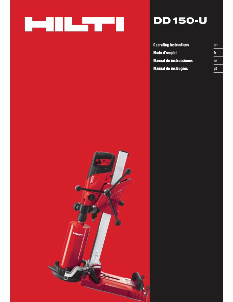
6.1.1 Adjusting the side handle 4
1. Release the side handle.2. Pivot the side handle into the desired position.3. Tighten the side handle securely by turning its
grip.4. Check to ensure that the side handle is tightened
securely.
6.1.2 Adjusting the depth gauge (when using thedrill stand)
1. Set the depth gauge to the desired depth.2. Secure the depth gauge by tightening the clamp-
ing screw.
6.1.3 Fastening the drill stand with ananchor 6 5
WARNINGUse an anchor suitable for the material on which youare working and observe the anchor manufacturer’sinstructions.
NOTEUse a metal expansion anchor (for example, a HiltiHKV M16) for fastening on uncracked concrete.
1. Set the anchor, of a type suitable for the materialon which you are working, at the ideal distancefrom the center of the point where the hole isto be drilled (267 mm (10 ½") when using theanchor base plate or 292 mm (11 ½") whenusing the combination base plate). The anchormust be capable of taking up a tensile force ofat least 12.6 kN (please refer to the anchor’sspecification).
2. Screw the clamping spindle into the anchor.3. Place the drill stand base plate over the spindle
and align it.
4. Screw the clamping nut onto the spindle but donot tighten it.
5. Level the base plate by turning the four levelingscrews. Take care to ensure that the levelingscrews make firm contact with the underlyingsurface.
6. Use a suitable open-end wrench to tighten theclamping nut on the clamping spindle.
7. Make sure that the drilling system is securedreliably.
6.1.4 Fitting the hand wheel 7The hand wheel can be fitted on either side of the drillstand.1. Fit the hand wheel onto the axle.2. Secure the hand wheel.
6.1.5 Mounting the machine on the drillstand 8 9 10 11 12 13
CAUTIONThe locking pins on the drill stand must be in theopen position and the carriage should be at the top ofthe column. The carriage must be locked in position.
1. Use the hand wheel to release the locking pin(turn counterclockwise) and then pull the lockingpin out.
2. Engage the interface plate on the machine withthe hooks on the drill stand.
3. Push the locking pin in and use the hand wheelto tighten it securely (turn clockwise).
4. Insert the switch locking device in the grip. Theswitch locking device can be used to lock theon/off switch in the “on” position for sustainedoperation.
5. Close the water valve on the side handle.6. Connect the water supply
6.1.6 Removing the machine from the drill standDANGERThe machine must be disconnected from the electricsupply.
The carriage must be locked in position.1. Close the water valve on the side handle.2. Disconnect the water supply.3. Remove the switch locking device from the grip.4. Use the hand wheel to release the locking pin
(turn counterclockwise).5. Pull the locking pin out of the slot.
en
11

VACUUM
VACUUM
6. Pivot the machine away from the drill stand.
6.1.7 Fastening the drill stand by vacuum 14
DANGEROverhead drilling with the machine secured only bythe vacuum base plate is not permissible.
CAUTIONMake yourself familiar with information containedin the operating instructions for the vacuum pumpand follow these instructions before using it.
WARNINGBefore beginning drilling and during operation itmust be ensured that the pressure gauge indicatorremains within the green area.
NOTEOptional when using the drill stand with the anchorbase plate: Screw the anchor base plate onto thevacuum base plate.
NOTEMake sure that the anchor base plate lies flat againstthe vacuum base plate and that the two plates are se-curely connected. Make sure that the core bit selectedfor use will not damage the vacuum base plate.
1. Turn (retract) the 4 leveling screws until theyproject approx. 5 mm beneath the combinationbase plate or, respectively, the vacuum baseplate.
2. Connect the vacuum pump to the vacuum con-nector on the combination base plate or vacuumbase plate.
3. Locate the center point of the hole to be drilled.4. Draw a line approximately 800 mm in length
from the center of the hole to be drilled towardswhere the drill stand is to be positioned.
5. Make a mark on the line at a distance of 292 mm(11½") from the center of the hole to be drilled.
6. Switch on the vacuum pump and press thevacuum release valve.
7. Bring the mark on the combination base plate orvacuum base plate into alignment with the line.
8. Once the drill stand has been positioned cor-rectly, release the vacuum release valve andpress the base plate against the work surface.
9. Level and steady the combination base plateor vacuum base plate by turning the 4 levelingscrews.
10. An additional means of securing the drilling sys-tem must be provided when drilling horizontally(e.g. a chain attached to an anchor, etc.).
11. Make sure that the drilling system is securedreliably.
6.1.8 Securing the system with the quick-releasebrace (e.g. between floor and ceiling)
1. Extend the hole center indicator and use it tohelp bring the drill stand into position at the holecenter.
2. Position the quick-release brace on the base plate(not on the level indicator or pressure gauge).
3. Apply slight pressure to the base plate by adjust-ing the quick-release brace.
4. Use the four leveling screws to level the baseplate. The bubble level on the base plate indicateswhen the base plate is level.
5. Tighten the quick-release brace securely.6. Check to ensure that the drill stand is secure.
6.1.9 Fastening the drill stand with the jackscrew
1. Fit the jack screw at the top end of the rail.2. Position the drill stand on the work surface.3. Level the base plate by turning the four leveling
screws.4. Secure the base plate by tightening the jack
screw.5. Check to ensure that the machine is fastened
securely.
6.1.10 Adjusting the drilling angle when usingthe drill stand with combination baseplate 15 16 17
(in 7.5° increments; adjustable to max. 45°)
en
12

CAUTIONThere is a risk of crushing the fingers in the pivotmechanism. Wear protective gloves.
1. At the foot of the drill stand, release the adjustinglever until the sliding nuts are disengaged.
2. Adjust the column to the desired angle.3. Tighten the adjusting lever until the sliding nuts
are fully engaged and the column is again securedin position.
6.1.11 Connecting the vacuum removalsystem 18
1. Unscrewthe cover from the water swivel / suctionhead.
2. Push the suction hose into the suction hoseconnector.
3. Close the water valve on the side handle.
6.1.12 Fitting the water connection 19
CAUTIONRegularly check the hoses for damage and makesure that the maximum permissible water supplypressure of 6 bar is not exceeded.
CAUTIONMake sure that the hose doesn’t come into contactwith rotating parts.
CAUTIONMake sure that the hose is not pinched and damagedas the carriage advances.
CAUTIONMax. water temperature: 40°C.
CAUTIONCheck the water supply system to ensure there areno leaks.
NOTETo avoid damage to the components, use only freshwater containing no dirt particles.
1. Close the cover on the water swivel / suctionhead.
2. Connect the water regulator to the machine.3. Connect the water supply (hose coupling).
6.1.13 Fitting the water collection system(accessory) 20
WARNINGUse of the water collection system in conjunctionwith a wet-type industrial vacuum cleaner is amandatory requirement for work on ceilings. Themachine must be positioned at an angle of 90° tothe ceiling. The seal used must be of the correctsize for the diamond core bit diameter.
NOTEUse of the water collection system allows water to beled away in controlled fashion, thus avoiding a messor damage to the surrounding area. Best results areachieved with a wet-type industrial vacuum cleaner.
1. Release the screw at the front of the rail.2. Push the water collector holder into position.3. Fit the screw and tighten it.4. Fit the water collector between the two movable
arms of the water collector holder.5. Press the water collector against the work surface
by turning the two screws on the water collectorholder.
6. Connect a wet-type industrial vacuum cleaner tothe water collector or fit a length of hose throughwhich the water can drain away.
6.1.14 Fitting the diamond core bit 21
DANGERTo avoid injury, use only genuine Hilti core bits andDD 150-U accessories. If using a machine with aBI+ chuck, only genuine Hilti core bits may be usedwith it.
CAUTIONThe core bit may become hot during use or duringsharpening. There is a risk of burning your hands.Wear protective gloves when changing the core bit.
CAUTIONDisconnect the supply cord plug from the poweroutlet.
NOTEIf using an alternative type of chuck, lock the drivespindle with a suitable open-end wrench and use
en
13

another suitable open-end wrench to tighten the corebit.
1. Engage the carriage locking system with thechannel and check that the channel is securelyfastened.
2. Open the chuck (BI+) by turning it in the directionof the open brackets symbol.
3. Push the diamond core bit into the chuck (BI+)from below, turning the core bit until the teeth inthe chuck engage with the core bit.
4. Close the chuck (BI+) by turning it in the directionof the closed brackets symbol.
5. Check that the diamond core bit is securelymounted in the chuck by pulling on the core bitand attempting to move it from side to side.
6.1.15 Selecting the speed 22
CAUTIONDo not change gear while the machine is running.Wait for the spindle to come to a halt.
1. Set the switch to the correct position accordingto the core bit diameter used (see Section 2.3).When turning the switch, rotate the core bit byhand at the same time until the switch can beengaged in the recommended position.
6.1.16 Removing the diamond core bit
CAUTIONThe core bit may become hot during use or duringsharpening. There is a risk of burning your hands.Wear protective gloves when changing the core bit.
CAUTIONDisconnect the supply cord plug from the poweroutlet.
NOTEIf using an alternative type of chuck, lock the drivespindle with a suitable open-end wrench and useanother suitable open-end wrench to release the corebit.
1. Engage the carriage locking system with thechannel and check that the channel is securelyfastened.
2. Open the chuck (BI+) by turning it in the directionof the open brackets symbol.
3. Pull the sleeve on the chuck in the direction ofthe arrow towards the machine. This releases thecore bit.
4. Remove the core bit.
7. Operation
WARNINGTake care to ensure that the supply cord and wateror vacuum cleaner hoses do not come into contactwith rotating parts.
WARNINGMake sure that the supply cord is not pinched anddamaged as the carriage advances.
CAUTIONThe machine and the drilling operation generate noise.Wear ear protectors. Excessive noise may damagethe hearing.
CAUTIONThe drilling operation may create dangerous splinters.Splintering material presents a risk of injury to theeyes and body. Wear eye protection and a hard hat.
CAUTIONDo not change gear while the machine is running.Wait until the drive spindle has stopped rotating.
en
14
WARNINGWhen using a two-part hole-starting aid, do notallow the machine to run without contact with thework surface.
7.1 TPS theft protection system (optional)NOTEThe machine may be equipped with the optional theftprotection system. If the machine is equipped withthis feature, it can be unlocked and made ready foroperation only with the corresponding TPS key.
7.1.1 Unlocking the machine1. Connect the supply cord to the electric supply
and press the “I” or “Reset” button on the groundfault circuit interrupter. The yellow theft protec-tion indicator LED blinks. The machine is nowready to receive the signal from the TPS key.
2. Hold the TPS key or the TPS watch strap buckleagainst the lock symbol. The machine is unlockedas soon as the yellow theft protection indicatorLED no longer lights.NOTE If, for example, the electric supply isbriefly interrupted due to a power failure ordisconnected when moving to a different work-place, the machine remains ready for operationfor approx. 20 minutes. In the event of a longerinterruption, the TPS key must be used again tounlock the machine.
7.1.2 Activation of the theft protection systemfor the machine
NOTEFurther detailed information on activation and useof the theft protection system can be found in theoperating instructions for the theft protection system.
7.2 Switching on and checking the ground faultcircuit interrupter (PRCD)
An isolating transformer must be used with machinesnot equipped with a PRCD.1. Plug the machine’s supply cord into an
earthed/grounded power outlet.2. Press the “I” or “Reset” button on the ground
fault circuit interrupter (PRCD).The drilling performance indicator lights orange.
3. Press the “0” or “Test” button on the groundfault circuit interrupter (PRCD).The indicator must go out.
4. WARNING If the indicator continues to light,further operation of the machine is not per-missible.Have the machine repaired by trainedpersonnel using genuine Hilti spare parts.Press the “I” or “Reset” button on the groundfault circuit interrupter (PRCD).The indicator must light.
7.3 Hand-guided dry drillingNOTEIf a considerable quantity of dust collects in the corebit this can cause the core bit to run out of balance.Remove the dust from the core bit.
7.3.1 Dry drilling with dust removalCAUTIONWhen working, always lead the vacuum cleanerhose away to the rear of the machine so that itcannot come into contact with the core bit.
CAUTIONPlease read the operating instructions for the vac-uum cleaner for information about disposal of thematerial collected.
NOTETo avoid electrostatic effects, use an anti-static vac-uum cleaner.
7.3.1.1 Fitting the hole-starting aidA different hole-starting aid is required for each corebit diameter.Fit the hole-starting aid into the open end of thediamond core bit.
7.3.1.2 Vacuum cleaner with power outlet forpower tools 23
CAUTIONDo not use slotted core bits when working with adust removal system.
NOTEThe optional operations are to be carried out whenthe two-part hole starting aid is used.
en
15

1. Bring the side handle into the desired positionand secure it (see Section 6.1.1).
2. Fit the hole-starting aid (optional operation).3. Plug the machine’s supply cord into the power
outlet on the vacuum cleaner.4. Plug the vacuum cleaner supply cord into the
power outlet and press the “Reset” button or the“I” button on the PRCD (see Section 7.2).
5. Position the machine at the point where the holeis to be drilled (hole center).
6. Press the on / off switch on the machine.NOTE The vacuum cleaner starts with a delayafter the machine is switched on. After switchingthe machine off, the vacuum cleaner continuesto run for a short time before switching itself off.
7. When beginning drilling, apply only light pres-sure until the core bit has centered itself and thenincrease the pressure. Drill to a depth of 3-5 mmto form a guide kerf (optional operation).
8. Switch the machine off by releasing the on /off switch and then wait until the core bit hasstopped rotating (optional operation).
9. Remove the hole-starting aid from the core bit(optional operation).
10. Position the core bit in the guide kerf and thenpress the on / off switch to continue drilling(optional operation).
7.3.1.3 Vacuum cleaner without power outlet forpower tools
CAUTIONDo not use slotted core bits when working with adust removal system.
NOTEThe optional operations are to be carried out whenthe two-part hole starting aid is used.
1. Bring the side handle into the desired positionand secure it (see Section 6.1.1).
2. Fit the hole-starting aid (optional operation).3. Plug the vacuum cleaner’s supply cord into the
power outlet and switch the vacuum cleaner on.4. Plug the machine’s supply cord into the power
outlet and press the “Reset” button or the “I”button on the PRCD (see Section 7.2).
5. Press the on / off switch on the machine.6. When beginning drilling, apply only light pres-
sure until the core bit has centered itself and thenincrease the pressure. Drill to a depth of 3-5 mmto form a guide kerf (optional operation).
7. Switch the machine off by releasing the on /off switch and then wait until the core bit hasstopped rotating (optional operation).
8. Remove the hole-starting aid from the core bit(optional operation).
9. Position the core bit in the guide kerf and thenpress the on / off switch to continue drilling(optional operation).
10. Allow the vacuum cleaner to run for a few sec-onds after switching off the machine in order toensure that the remaining dust is removed.
7.3.2 Working without dust removal
NOTEUse slotted core bits when drilling without a dustremoval system.
NOTEThe optional operations are to be carried out whenthe two-part hole starting aid is used.
CAUTIONDisconnect the machine from the power outlet be-fore removing the core from the slotted core bit.
DANGERWear respiratory protection.
NOTEDust is released in all directions. Drilling without adust removal system, especially overhead drilling,is very unpleasant and optimum performance is notachieved. Overhead drilling without use of dust re-moval system is therefore not recommended. For drycoring it is recommended that the dust removal at-tachment and a suitable vacuum cleaner are alwaysused.
1. Secure the side handle in the desired position.2. Fit the hole-starting aid (optional operation).3. Insert the supply cord plug in the power outlet
and then press the “Reset” button or “I” buttonon the PRCD (if applicable).
4. Position the machine at the point where the holeis to be drilled (hole center).
5. Press the on / off switch on the machine.
en
16
6. When beginning drilling, apply only light pres-sure until the core bit has centered itself and thenincrease the pressure. Drill to a depth of 3-5 mmto form a guide kerf (optional operation).
7. Switch the machine off by releasing the on /off switch and then wait until the core bit hasstopped rotating (optional operation).
8. Remove the hole-starting aid from the core bit(optional operation).
9. Position the core bit in the guide kerf and thenpress the on / off switch to continue drilling(optional operation).
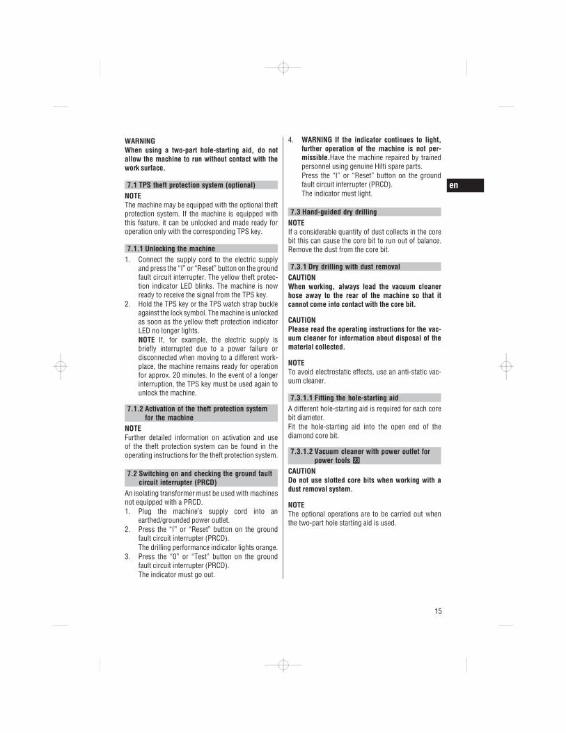
7.4 Hand-guided wet drilling without use of awater collection system
WARNINGWater must not be allowed to run over the motorand cover.
WARNINGA water collection system with wet-type vacuumcleaner must be used when drilling in an upwardsdirection.
NOTEThe optional operations are to be carried out whenthe two-part hole starting aid is used.
1. Bring the side handle into the desired positionand secure it (see Section 6.1.1).
2. Fit the hole-starting aid (optional operation).
3. Plug the supply cord into the power outlet andpress the “Reset” button or the “I” button on thePRCD.
4. Position the machine at the point where the holeis to be drilled (hole center).
5. Slowly open the water flow regulator until thedesired volume of water is flowing.
6. Press the on/off switch on the machine.7. When beginning drilling, apply only light pres-
sure until the core bit has centered itself and thenincrease the pressure. Drill to a depth of 3-5 mmto form a guide kerf (optional operation).
8. Switch the machine off by releasing the on /off switch and then wait until the core bit hasstopped rotating (optional operation).
9. Remove the hole-starting aid from the core bit(optional operation).
10. Position the core bit in the guide kerf and thenpress the on / off switch to continue drilling(optional operation).
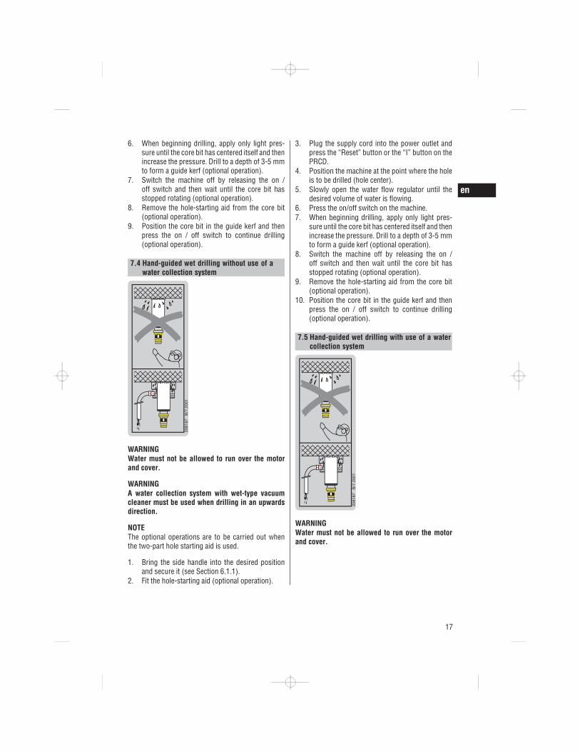
7.5 Hand-guided wet drilling with use of a watercollection system
WARNINGWater must not be allowed to run over the motorand cover.
en
17

WARNINGA water collection system with wet-type vacuumcleaner must be used when drilling in an upwardsdirection.
NOTEThe optional operations are to be carried out whenthe two-part hole starting aid is used.
NOTEStart the wet-type vacuum cleaner manually beforeopening the water supply valve and switch it off againmanually when the drilling operation is completedand after closing the water supply valve.
NOTEDo not use the power outlet on the vacuum cleaner.
1. If a water extraction system (vacuum cleaner) isused, switch it on.
2. Secure the side handle in the desired position.3. Fit the hole-starting aid (optional operation).4. Plug the supply cord into the power outlet and
press the “Reset” button or the “I” button on thePRCD.
5. Position the machine at the point where the holeis to be drilled (hole center).
6. Slowly open the water flow regulator until thedesired volume of water is flowing.The indicator on the side handle can be used tocheck the water flow.
7. Press the on/off switch on the machine.8. When beginning drilling, apply only light pres-
sure until the core bit has centered itself and thenincrease the pressure. Drill to a depth of 3-5 mmto form a guide kerf (optional operation).
9. Switch the machine off by releasing the on /off switch and then wait until the core bit hasstopped rotating (optional operation).
10. Remove the hole-starting aid from the core bit(optional operation).
11. Position the core bit in the guide kerf and thenpress the on / off switch to continue drilling(optional operation).
7.6 Wet drilling using the drill stand 24 25
WARNINGWater must not be allowed to run over the motorand cover.
WARNINGA water collection system with wet-type vacuumcleaner must be used when drilling in an upwardsdirection.
WARNINGStop working if the vacuum removal system nolonger functions.
WARNINGThe end stop screw must be fitted at the end of theguide rail when drilling in an upwards direction.
CAUTIONReleasing the tilt mechanism on the drill stand maycause the column to tilt suddenly.
NOTEStart the wet-type vacuum cleaner manually beforeopening the water supply valve and switch it off again
en
18
manually when the drilling operation is completedand after closing the water supply valve.
NOTEDo not use the power outlet on the vacuum cleaner.
1. Open the water flow regulator on the side han-dle slowly until the desired volume of water isflowing.The indicator on the side handle can be used tocheck the water flow.
2. Use the switch locking device to switch themachine on for sustained operation.The drilling performance indicator lights orange.
3. Release the carriage locking mechanism.4. Turn the hand wheel until the diamond core bit
is in contact with the work surface.5. When beginning drilling, apply only light pres-
sure until the core bit has centered itself and thenincrease the pressure.
6. Regulate the contact pressure while observingthe drilling performance indicator.NOTE The drilling performance indicator lightsorange after switching on. Optimum drilling per-formance is achieved when the drilling perfor-mance indicator shows a green light. If thedrilling performance indicator shows a red light,reduce the pressure applied to the core bit.
7.7 Using the Rota-Rail (column swivel)CAUTIONDo not use the Rota-Rail as a column extension.
The Rota-Rail allows quick and easy access to thehole being drilled, or to the core, with no need topartly or fully dismantle the system.1. Switch the machine off.2. Lock the carriage on the channel by engaging the
carriage locking mechanism and check that it issecurely attached.
3. Remove the end stop screw from the end of therail.
4. Attach the Rota-Rail so that the toothed racksare facing the same direction.
5. Tighten the screw on the Rota-Rail securely.6. Release the carriage lock and run the carriage
along the rail onto the Rota-Rail.7. Release the Rota-Rail fastening screw and pivot
the machine with the Rota-Rail to the left or rightto provide access to the hole being drilled.
8. Remove the core or change the core bit.
9. Pivot the machine back to its original position,tighten the Rota-Rail fastening screw securelyand then run the carriage back onto the columnof the drill stand in order to continue drilling.
10. After removing the Rota-Rail, refit the end stopscrew to the end of the rail.
7.8 Procedure in the event of the core bitsticking
In the event of the core bit sticking, the clutch will slipuntil the user switches the power tool off. The corebit can be released by taking the following action:7.8.1 Using an open-end wrench to release the
core bit1. Disconnect the supply cord plug from the power
outlet.2. Grip the core bit with a suitable open-end wrench
close to the connection end and release the corebit by rotating it.
3. Plug the machine’s supply cord into the poweroutlet.
4. Resume the drilling operation.
7.8.2 Using the hand wheel to release a core bit(when using the drill stand)
1. Disconnect the supply cord plug from the poweroutlet.
2. Release the core bit from the hole by turning itwith the hand wheel.
3. Plug the machine’s supply cord into the poweroutlet.
4. Resume the drilling operation.
7.9 DismantlingCAUTIONDisconnect the supply cord plug from the poweroutlet.
1. For instructions on removing the diamond corebit, please refer to the section “Removing thediamond core bit”.
2. Remove the core if necessary.
7.10 Disposing of drilling slurryPlease refer to the section “Disposal”.
7.11 Transport and storageOpen the water flow regulator before putting themachine into storage.
en
19

CAUTIONWhen temperatures drop below zero, check to en-sure that no water remains in the power tool.
WARNINGDo not lift the machine and/or the drill stand bycrane.
8. Care and maintenanceCAUTIONDisconnect the supply cord plug from the poweroutlet.
8.1 Care of cutting tools and metal partsRemove any dirt adhering to the surface of cuttingtools, the chuck and drive spindle and protect theirsurfaces from corrosion by rubbing them with an oilycloth from time to time.Always keep the connection end clean and lightlygreased.
8.2 Care of the machineCAUTIONKeep the machine, especially its grip surfaces,clean and free from oil and grease. Do not usecleaning agents which contain silicone.
The outer casing of the machine is made from impact-resistant plastic.Never operate the machine when the ventilation slotsare blocked. Clean the ventilation slots carefully usinga dry brush. Do not permit foreign objects to enterthe interior of the machine. Clean the outside of themachine at regular intervals with a slightly dampcloth. Do not use a spray, steam pressure cleaningequipment or running water for cleaning. This maynegatively affect the electrical safety of the machine.Clean the chuck and the clamping segments with acloth at regular intervals and lubricate the parts withHilti lubricant spray. Remove any particles of foreignmatter from the chuck.Remove the filter from the water inlet on the sidehandle occasionally and flush the filter mesh throughwith water in the direction opposite to the normalwater flow.If the water flow indicator is dirty, remove it fromthe machine and clean it as necessary. Do not useabrasive cleaning agents or sharp objects to clean thesight glass. This may adversely affect the functionalityof the water flow indicator.
8.3 MaintenanceWARNINGRepairs to the electrical section of the machine maybe carried out only by trained electrical specialists.
Check all external parts of the power tool for damageat regular intervals and check that all controls operatefaultlessly. Do not operate the power tool if partsare damaged or when the controls do not functionfaultlessly. If necessary, the power tool should berepaired by Hilti Service.
8.4 Replacing the carbon brushes 26
NOTEThe indicator lamp with wrench symbol lights upwhen the carbon brushes need to be replaced.
DANGERThe machine may be operated, serviced and re-paired only by trained, authorized personnel. Thispersonnel must be particularly informed of anypossible hazards. Failure to observe the followinginstructions may result in contact with dangerouselectric voltage.
1. Disconnect the machine from the electric supply.2. Open the carbon brush covers on the left-hand
and right-hand side of the motor.3. Take note of how the carbon brushes are fitted
and how the conductors are positioned. Removethe worn carbon brushes from the machine.
4. Fit the new carbon brushes just as the old oneswere fitted (spare part numbers: 100 127 V car-bon brush set: 2006844, 220 240 V carbon brushset: 2006843).NOTE Take care to avoid damaging the insulationon the indicator lead as you insert the brushes.
en
20

5. Close the carbon brush covers on the left-handand right-hand side of the motor and tighten theretaining screws.
6. Allow the tool to run in for approx. 1 min. underno load.NOTE After replacing the carbon brushes theindicator lamp will go out after the machine hasrun for approx. 1 minute.
8.5 Checking the power tool after care andmaintenance
After carrying out care and maintenance, check thatall protective and safety devices are fitted and thatthey function faultlessly.
8.6 Adjusting the play between rail and carriageNOTEPlay between the rail and the carriage can be adjustedby turning the carriage play adjustment screws.
Use an Allen key to tighten the carriage adjustmentscrews to a torque of 5 Nm (finger-tight) and thenturn the screws back / of a turn.The carriage is correctly adjusted if it remains inposition when no core bit is fitted but moves downunder its own weight when a core bit is fitted.
9. Troubleshooting
Fault Possible cause Remedy
The machine doesn’t start. Interruption in the electric supply. Plug in another electric applianceand check whether it works. Checkthe plug connections, supply cordsand extension cords, PRCD andelectric supply.
On/off switch defective. If necessary, the power tool shouldbe repaired by Hilti Service.
Interruption in the electric supply. Check the supply cord, extensioncord, supply cord plug, PRCD andhave them replaced by a qualifiedelectrician if necessary.
The electronics are defective. The machine should be repaired byHilti Service.
Water in the machine. Dry the machine.The machine should be repaired byHilti Service.
The service indicator lights. The carbon brushes are worn; themachine will continue to run for afew hours.
The carbon brushes should bechanged.See section: 8.4 Replacing the car-bon brushes 26
The machine doesn’t start andthe service indicator lights.
The carbon brushes are worn. Replace the carbon brushes.See section: 8.4 Replacing the car-bon brushes 26
The machine doesn’t start,carbon brushes have beenchanged, service indicatorlights.
A fault has occurred in the powertool.
If necessary, the power tool shouldbe repaired by Hilti Service.
en
21

Fault Possible cause Remedy
The machine doesn’t run andthe service indicator blinks.
The machine has overheated. Wait a few moments until the mo-tor has cooled down or allow it torun under no load in order to speedup the cooling-down process.
Overload error. Switch the machine off and onagain.
The machine doesn’t start,theft protection indicatorblinks yellow.
The power tool has not been un-locked (tools with optional theftprotection system).
Use the TPS key to unlock thepower tool.
The motor runs. The diamondcore bit doesn’t rotate.
Gear selector doesn’t engage. Move the gear selector until felt toengage.
The gearing is defective. If necessary, the machine shouldbe repaired by Hilti Service.
Drilling speed drops. The diamond core bit is polished. Sharpen the diamond core bit on asharpening plate with water flow-ing.
The diamond core bit is polished. The wrong type of core bit hasbeen used. Seek advice from Hilti.
Water pressure / flow rate too high. Reduce the water flow rate by ad-justing the flow regulator.
The core is stuck in the core bit. Remove the core.Maximum drilling depth is reached. Remove the core and use a core bit
extension.The diamond core bit is defective. Check the diamond core bit for
damage and replace it if necessary.The slip clutch is disengaging pre-maturely or slipping.
If necessary, the machine shouldbe repaired by Hilti Service.
The carriage is locked. Unlock the carriage.The water flow rate is too low. Adjust (open) the water flow regu-
lator.Check the water supply.
The motor cuts out. The machine has stalled. Guide the machine straight.The machine is too hot. The motoroverheating protection system hasbeen activated.
Relieve the load on the machineand press the switch several timesto restart.
The electronics are defective. The machine should be repaired byHilti Service.
The cooling fan is defective. The machine should be repaired byHilti Service.
The handwheel turns butdoesn’t engage.
The retaining pin is broken. Fit a new retaining pin.
Water escapes at the waterswivel or gear housing.
The water pressure is too high. Reduce the water pressure.The shaft seal is defective. The machine should be repaired by
Hilti Service.No water flows. The filter or water flow indicator is
blocked.Remove the filter or water flowindicator and flush it through.
en
22

Fault Possible cause Remedy
The diamond core bit cannotbe fitted into the chuck.
The core bit connection end orchuck is dirty or damaged.
Clean the connection end /chuck orreplace if necessary.
Water escapes from thechuck during operation.
The core bit is not screwed se-curely into the chuck.
Tighten it securely.
The core bit connection end / chuckis dirty.
Clean the connection end / chuck.
The chuck or connection end sealis defective.
Check the seal and replace it if nec-essary.
Excessive play in the drillingsystem.
The core bit is not screwed se-curely into the chuck.
Tighten it securely.
The leveling screws or clampingspindle are not tightened.
Tighten the leveling screws orclamping spindle.
Excessive play at the carriage. Adjust the play between rail andcarriage.See section: 8.6 Adjusting the playbetween rail and carriage
The core bit connection end is de-fective.
Check the connection end and re-place it if necessary.
10. Disposal
Most of the materials from which Hilti machines or appliances are manufactured can be recycled. Thematerials must be correctly separated before they can be recycled. In many countries, Hilti has already madearrangements for taking back old machines and appliances for recycling. Ask Hilti customer service or yourHilti representative for further information.
Recommended pretreatment for disposal of drilling slurryNOTEThe disposal of drilling slurry directly into rivers, lakes or the sewerage system without suitable pretreatmentpresents environmental problems. Ask the local public authorities for information about current regulations.
1. Collect the drilling slurry (e.g. using a wet-type industrial vacuum cleaner)2. Allow the drilling slurry to settle and dispose of the solid material at a construction waste disposal site
(the addition of a flocculent may accelerate the separation process).3. The remaining water (alkaline, pH value > 7) must be neutralized by the addition of an acidic neutralizing
agent or diluted with a large volume of water before it is allowed to flow into the sewerage system.
Recommended pretreatment for disposal of drilling slurryNOTEFrom the environmental and health point of view, the disposal of drilling dust can be problematic. Ask the localpublic authorities for information about current regulations.
en
23

11. Manufacturer’s warrantyHilti warrants that the tool supplied is free of defectsin material and workmanship. This warranty is validso long as the tool is operated and handled correctly,cleaned and serviced properly and in accordance withthe Hilti Operating Instructions, and the technicalsystem is maintained. This means that only originalHilti consumables, components and spare parts maybe used in the tool.
This warranty provides the free-of-charge repair orreplacement of defective parts only over the entirelifespan of the tool. Parts requiring repair or replace-ment as a result of normal wear and tear are notcovered by this warranty.
Additionalclaims are excluded, unless stringent na-tional rules prohibit such exclusion. In particular,Hilti is not obligated for direct, indirect, inciden-tal or consequential damages, losses or expensesin connection with, or by reason of, the use of,or inability to use the tool for any purpose. Im-plied warranties of merchantability or fitness for aparticular purpose are specifically excluded.
For repair or replacement, send the tool or relatedparts immediately upon discovery of the defect tothe address of the local Hilti marketing organizationprovided.
This constitutes Hilti’s entire obligation with regardto warranty and supersedes all prior or contempo-raneous comments and oral or written agreementsconcerning warranties.
en
24

*434950*
4349
50
Hilti CorporationLI-9494 SchaanTel.: +423 / 234 21 11Fax: +423 / 234 29 65www.hilti.com
Hilti = registered trademark of Hilti Corp., Schaan W 3982 0711 00-Pos. 3 1 Printed in Germany © 2011Right of technical and programme changes reserved S. E. & O. 434950 / C
![E } u o } u u v / } u u v Z } µ ] Z u ] vrevit.downloads.autodesk.com/download/2018RVT_RTM/... · W u µ o u v ] WW u } o ] o/ z^ dd/E'^ z^hE E ^, Kt^^ dd/E'^^h ' EW u](https://img.dokumen.tips/doc/110x75/5e2fab23a3ddad4b8a28eaa1/e-u-o-u-u-v-u-u-v-z-z-u-w-u-o-u-v-ww-u-o-o-z-dde.jpg)
![>dD E J Æ u - Extreme Scottish Triathlon · >dD E J Æ u ^ } ] Z d ] Z o } v î ì î ì >dD E J Æ u ^ } ] Z d ] Z o } v î ì î ì](https://img.dokumen.tips/doc/110x75/5ffe21b75ed6c011fe6735c5/dd-e-j-u-extreme-scottish-triathlon-dd-e-j-u-z-d-z-o-v.jpg)