Embed Size (px)
Citation preview

Affiliated Club
Operations Guide Version 1.6

Operations Guide
Amateur Radio Euless
1102 West Euless Blvd.
Euless, TX 76040
442.900+ 110.9
www.w5eul.com
© 2014 Amateur Radio Euless
Acknowledgements
Skywarn® is a registered trademark of the National Oceanic and Atmospheric Administration.
Yaesu® is a registered trademark of the Vertex Standard Co., Ltd.
Powerpole® is a registered trademark of Anderson Power Products
Dallas County RACES Cloud Cowboy 2013
National Weather Service office of Fort Worth
Tarrant County RACES
DFW Area Ham Radio Interoperability Group
The City of Euless Texas
John Galvin, N5TIM
Dan O’Connor, KE7HLR
Phillip Bailey, WY3Q
American Radio Relay League

i | ARE Operations Guide Version 1.6
Amateur Radio Euless (ARE) does not warrant or make representations or endorsements as
to the quality, content, accuracy, or completeness of the information, text, graphics, links and
other items contained in this manual or any website links contained within. Such materials
have been compiled from a variety of sources and are subject to change without notice.
Certain materials contained herein may be entitled to copyright, service mark, or trademark
protection under state and federal law. Such materials remain the property of their respective
owners, and the unauthorized use or republication of those materials may be subject to a legal
action for infringement. Except to the extent allowed by law, the use or republication of the
materials contained on this website is prohibited without the written permission of ARE.
Some of the links on this page and subsequent pages may lead to resources outside ARE. The
presence of external links should not be construed as an endorsement of these sites or their
content by ARE. ARE is not responsible for, and specifically disclaims responsibility for, the
content of any such external link.
ARE respects one’s privacy and will endeavor to use any requested data solely for purposes
of conducting official business. However, be aware that correspondence, e-mail, and other
documents submitted to ARE may have to be made available for public review and
inspection, as well as photocopying by members of ARE, in accordance with the Texas
Public Information Act.
DISCLAIMER
ARE Operations Guide Version 1.6 ii
The Amateur Radio Euless Operations Guide is an orientation and reference guide for
members of the Euless Amateur Radio Club. This guide includes information about club
operations, club equipment, emergency operations, and other reference material.
The purpose of this guide is to provide the basic information needed to be a contributing
member of the club. It contains information on club meetings, activities, basic operations of
the club radio equipment, and reference material aiding the club member in preparing to
serve the City of Euless during emergency operations.
This guide also contains detailed information on frequency plans that aid in mutual aid
communications with other local and county amateur radio organizations. We encourage
you to use this information to prepare yourself and your radio equipment to serve during
emergency events.
To download a copy of this guide, please visit the Amateur Radio Euless website at
www.w5eul.com. The guide is available in the Manuals section of the site.
Your comments are welcome at [email protected].
INTRODUCTION

iii | ARE Operations Guide Version 1.6
AMATEUR RADIO EULESS ................................................................................................................................ 2
Who We Are ................................................................................................................................................. 3
What We Do ................................................................................................................................................. 3
Supported Agencies ...................................................................................................................................... 3
Club Meetings ............................................................................................................................................... 4
Club Repeater ............................................................................................................................................... 4
Club Station .................................................................................................................................................. 4
Weekly Net ................................................................................................................................................... 4
Club Yahoo Group ........................................................................................................................................ 4
Radio License Testing .................................................................................................................................. 4
Training......................................................................................................................................................... 5
Affiliated Clubs ............................................................................................................................................ 5
EchoLink....................................................................................................................................................... 6
Winlink ......................................................................................................................................................... 7
ARE Club Bylaws ......................................................................................................................................... 8
ARE Club License ...................................................................................................................................... 11
ARE CLUB EQUIPMENT ................................................................................................................................... 12
Yaesu FT-7800R VHF/UHF ....................................................................................................................... 13
Yaesu FT-8800R VHF/UHF ....................................................................................................................... 16
Yaesu FT-897D HF/VHF/UHF .................................................................................................................. 19
Ameritron SDC-102 Screwdriver Antenna Controller ............................................................................... 22
MFJ-4245MV Power Supply ...................................................................................................................... 23
Portable Go-Box ......................................................................................................................................... 24
Portable Go-Box Setup Procedure .............................................................................................................. 25
EMERGENCY OPERATIONS ............................................................................................................................ 28
Preparedness ............................................................................................................................................... 29
Euless PD Emergency Operations Center................................................................................................... 29
Tarrant County RACES .............................................................................................................................. 29
ARE Club Activation .................................................................................................................................. 31
Communications Equipment ....................................................................................................................... 31
Euless Community Emergency Response Team ........................................................................................ 31
RACES Skywarn Spotter Net ..................................................................................................................... 32
CONTENTS

ARE Operations Guide Version 1.6 iv
APPENDEX ............................................................................................................................................................ 40
Frequency Plans .......................................................................................................................................... 41
Club Net Script ........................................................................................................................................... 46
Phonetic Alphabet ....................................................................................................................................... 48
H.A.N.D ...................................................................................................................................................... 48
Net Do’s and Don’ts ................................................................................................................................... 49
Basic Communications Go-Kit ................................................................................................................... 50
Anderson Power Poles ................................................................................................................................ 51
Resource Typing ......................................................................................................................................... 52
Common Items for all Communications Resource Functions (CRF) .................................................. 52
Communications Resource Function S - (Shadow | VHF/UHF) .......................................................... 52
Communications Resource Function B - (Base | VHF/UHF) .............................................................. 52
Communications Resource Function M - (Mobile | VHF/UHF) .......................................................... 53
Communications Resource Function H - (Long-Range Communications | HF) .................................. 53
Communications Resource Function DA - (Data - APRS Operations | VHF/UHF) ............................ 53
Communications Resource Function DT - (Data – Resource Tracking| VHF/UHF) ........................... 53
Communications Resource Function DM - (Tactical Data Messaging | VHF/UHF) ........................... 53
Communications Resource Function DH - (Long-Range Data Messaging | HF) ................................ 54
Communications Resource Function DN - (Data Networking | UHF) ................................................ 54
Communications Resource Function AV - (Amateur TV | UHF) ........................................................ 54
CRF Assignment Durations ........................................................................................................................ 54
GLOSSARY ........................................................................................................................................................... 56
MAPS .................................................................................................................................................................... 60
City of Euless .............................................................................................................................................. 61
Tarrant County Mapsco .............................................................................................................................. 62
Dallas County Mapsco ................................................................................................................................ 63
North Texas Counties SKYWARN Frequencies ........................................................................................ 64
Euless Warning Sirens ................................................................................................................................ 65
BAND PLAN .......................................................................................................................................................... 66
REVISIONS .......................................................................................................................................................... 67
NOTES ................................................................................................................................................................... 68
CONTENTS

1 | ARE Operations Guide Version 1.6

AMATEUR RADIO EULESS

3 | ARE Operations Guide Version 1.6
Who We Are
Amateur Radio Euless is an association of members who have a common interest in the avocation of Amateur Radio.
Our members have diverse interests. You will find among our ranks those who enjoy building their own radios and those
who enjoy contacting other amateurs around the world, those who perform community service, and those who simply
enjoy the chance to meet new people over the air. Amateur Radio is a worldwide service that can be an enriching,
educational, lifelong activity. The club is affiliated with the American Radio Relay League (ARRL).
What We Do
Our club holds monthly meetings on the second Wednesday of each month in the Euless Police Department’s
Emergency Operations Center (EOC) These meetings are an opportunity for us to learn about the latest developments in
Amateur Radio, plan and organize club events, and to share information. We have an informative presentation at each
meeting on a wide variety of topics related to Amateur Radio communications.
Amateur Radio is a licensed radio service. To earn a license requires passing examinations regulated by the Federal
Communications Commission. The club is not just for people who are already licensed. The members and officers of
Amateur Radio Euless are excited to share our enjoyable and interesting avocation with anyone who is curious about
Amateur Radio and communications. We are also interested in helping people earn their own Amateur Radio license.
The relationship of the ARE Radio club to the EOC is a volunteer effort. The EOC operates during emergencies where
one agency (fire or police, for example) is not able to handle the disaster alone, and it is a place where city planners and
heads of police, fire, and other agencies get together in one location to deal with it. Amateur Radio Operators from the
club have a location in the EOC to handle emergency communications should the standard systems go down, and to
provide backup communication services when needed.
The R.A.C.E.S. members of the club also provide trained communications personnel (amateur radio operators) to assist
the National Weather Service, and other similar community agencies, in providing communications support for sporting
events and a variety of public service events. During disaster events ARE and RACES radio operators assist local,
county, and state public service organizations by providing vital additional emergency communications capacity.
Supported Agencies
City of Euless Office of Emergency Management
Euless Community Emergency Response Team (CERT)
Northeast Tarrant and Denton County Child Abduction Response Team (NETDC-CART)
National Weather Service
Tarrant County R.A.C.E.S
North Texas Amateur Radio Emergency Service - NTXARES
AMATEUR RADIO EULESS

ARE Operations Guide Version 1.6 4
Club Meetings
Amateur Radio Euless meets monthly on the 2nd Wednesday of each month. The meeting time is 19:00 at the Euless
Police Department EOC located at 1102 W. Euless Blvd., Euless, TX 76040 (On the Northwest corner of Hwy 10 and
Industrial Blvd.) Club meetings are open to any person who is interested in amateur radio. For more information about
the club, please send an e-mail to [email protected].
Club Repeater
Amateur Radio Euless has a UHF repeater on 442.900 MHz RX frequency and 447.900 MHZ TX frequency with a
110.9 PL tone. The Euless club repeater is located on top of the Euless Police Department. It is a Kenwood repeater
with a Pacific Research controller. The repeater has emergency power in the form of a generator and battery.
Club Station
Amateur Radio Euless has a club station located at the Euless Police Department. The station includes an Icom 706
MKII HF radio and a Yaesu 7800 VHF/UHF radio. The club HF antenna is a High Sierra screwdriver antenna along
with a Comet tri-band UHF/VHF antenna. The club also has two Go Kits that include a Yaesu 897-D HF/VHF/UHF
radio, Yaesu 8800 VHF/UHF radio, Little Tar Heel II screwdriver antenna, Rigrunner, MFJ 4245V power supply, MFJ-
1725B mag mount dual band antenna, Ameritron SDC-102 Screwdriver Antenna Controller, and all appropriate user
guides and documentation.
Weekly Net
Each week Amateur Radio Euless has a weekly check-in net located on the Euless Club Repeater. The weekly net is
each Tuesday at 20:30 Central Time and is open to any amateur radio operator. The net is also on EchoLink, just search
for W5EUL-R. The net includes ham news, club officer comments, tech talk, swap meet, other announcements from
stations that checked in to the net, and then general conversations.
Club Yahoo Group
Amateur Radio Euless has established a Yahoo group to facilitate communication to the club and other interested
parties. The group is the primary notification for all club socials and used as a reminder for club events. This group is
restricted to members only.
Use this URL to access the Yahoo group page. http://groups.yahoo.com/neo/groups/eulessarc/info
If you do not have a Yahoo account, you will have to create one. Follow this link with further help on how to setup
a Yahoo account and to join the group http://www.wikihow.com/Join-a-Yahoo!-Group
Request to join the group. The group administrator has to approve all membership requests.
Radio License Testing
Amateur Radio Euless offers amateur radio license testing to anyone who wants to get there license or to upgrade their
ticket. Testing will be generally given after the monthly club meeting. For more information on license testing and to
schedule a test, please send an e-mail to [email protected].
AMATEUR RADIO EULESS
5 | ARE Operations Guide Version 1.6
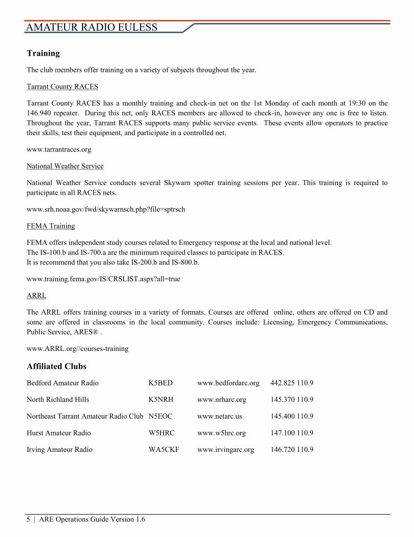
Training
The club members offer training on a variety of subjects throughout the year.
Tarrant County RACES
Tarrant County RACES has a monthly training and check-in net on the 1st Monday of each month at 19:30 on the
146.940 repeater. During this net, only RACES members are allowed to check-in, however any one is free to listen.
Throughout the year, Tarrant RACES supports many public service events. These events allow operators to practice
their skills, test their equipment, and participate in a controlled net.
www.tarrantraces.org
National Weather Service
National Weather Service conducts several Skywarn spotter training sessions per year. This training is required to
participate in all RACES nets.
www.srh.noaa.gov/fwd/skywarnsch.php?file=sptrsch
FEMA Training
FEMA offers independent study courses related to Emergency response at the local and national level.
The IS-100.b and IS-700.a are the minimum required classes to participate in RACES.
It is recommend that you also take IS-200.b and IS-800.b.
www.training.fema.gov/IS/CRSLIST.aspx?all=true
ARRL
The ARRL offers training courses in a variety of formats. Courses are offered online, others are offered on CD and
some are offered in classrooms in the local community. Courses include: Licensing, Emergency Communications,
Public Service, ARES® .
www.ARRL.org//courses-training
Affiliated Clubs
Bedford Amateur Radio K5BED www.bedfordarc.org 442.825 110.9
North Richland Hills K5NRH www.nrharc.org 145.370 110.9
Northeast Tarrant Amateur Radio Club N5EOC www.netarc.us 145.400 110.9
Hurst Amateur Radio W5HRC www.w5hrc.org 147.100 110.9
Irving Amateur Radio WA5CKF www.irvingarc.org 146.720 110.9
AMATEUR RADIO EULESS

ARE Operations Guide Version 1.6 6
Echo Link
What is EchoLink?
EchoLink uses VoIP (Voice Over Internet Protocol) to allow licensed Amateur Radio Operators to communicate
with other Amateurs via the Internet.
It is primarily a Windows based application and is offered free of charge at http://www.echolink.org.
There is also a new EchoLinux and EchoMac available.
Now available is an iPhone and Android app that can be used to connect to operators around the world while you are
on the go.
It was developed by Jonathan Taylor (K1RFD) in 2002.
The system allows reliable worldwide connections to be made between radio amateurs, greatly enhancing Amateur
Radio's communications capabilities. In essence it is the same as other VoIP applications (such as Skype), but with
the unique addition of the ability to link to an amateur radio station's transceiver.
Before using the system it is necessary for a prospective user's call sign to be validated. The EchoLink system
requires that each new user provide positive proof of license and identity before his or her call sign is added to the
list of validated users.
Rules
Keep in mind that all the rules you have to comply with on the radio also apply to EchoLink.
You must ID your station at least every 10 minutes and then at the end of your QSO.
You must operate within your license class.
How to install EchoLink
To download the software, visit www.echolink.org, then click on “Download” on the left.
Follow the directions to install the software.
Once the software is installed you will have to visit www.echolink.org/validation to validate your license. Follow
the directions on how to validate.
How to use EchoLink
Open the EchoLink Program
On the top under the Menu Bar you will see several icons click on the Binoculars
Type the call sign of the station you are wanting to connect. Double click the stations call sign to begin QSO.
Use the space bar as your PTT button. Press space bar and release to TX and then press again and release to RX.
For more detailed information and directions on how to install and use EchoLink visit
http://w5eul.com/docs/EchoLink.pdf.
AMATEUR RADIO EULESS

7 | ARE Operations Guide Version 1.6
Winlink
Winlink is the ability to use amateur radio to send packet mail to other stations when the internet is not available. This
allows for the passing of critical information without tying up air time and providing accuracy.
This address is not a point of contact for the club. It will be used for training purposes or when we are activated.
How to use Winlink to receive a message.
1. Open the Winlink program
2. Go to “Files” menu
3. Then click on RMS Express Setup
4. Make sure your call sign and grid square are correct then click “Update”
5. Next to Open Session: Select “Packet WL2K” from the dropdown menu
6. Then click Open Session. This will open up a new window
7. Click “Setup” menu
8. Choose your TNC, Serial Port, and baud rate then click “Update”
9. Click on Channel Selection. Choose the station from the list and tune your radio to that frequency.
10. Click on “Start” This will go and check to see if you have any messages waiting.
11. Close the Packet Winlink 2000 Session window.
12. Click on “Inbox” and you will see your messages in there. Once they have been read the messages will be moved
to “Read Items”
How to use Winlink to receive a message.
1. Open the Winlink program
2. Go to “Files” menu
3. Then RMS Express Setup
4. Make sure your call sign and grid square are correct then click “Update”
5. Click on “Message”
6. Then click on “New Message”
7. In the “To” box, place the address of the person who you need to send the message to.
8. Then click on “Post to Outbox”
9. Then follow steps 5 – 12 on “How to use Winlink to receive a message above”.
For more detailed information and directions on how to install and use Winlink visit
http://w5eul.com/docs/WinLink.pdf.
AMATEUR RADIO EULESS

ARE Operations Guide Version 1.6 8
ARE Club Bylaws
Second Revision February 8, 2012
ARTICLE 1 – NAME
1.01 The name of the club shall be AMATEUR RADIO EULESS.
ARTICLE 2 – PURPOSE
2.01 The club is an organization with the following objectives:
A. To work in association with the Euless Office of Emergency Management and Tarrant County RACES.
B. To promote the growth and favorable public image of Amateur Radio.
C. To advise and expand the Amateur Radio Community.
ARTICLE 3 – MEMBERSHIP
3.01 Membership shall be comprised of voting and non-voting members, as defined in ARTICLE 4 and ARTICLE 5.
3.02 Membership in the club shall be restricted to individuals who have interest in the objectives of the club.
3.03 Membership will be allowed any Amateur Radio operator or others upon the recommendation of any member and
approved by a majority of the voting members by sealed ballot.
ARTICLE 4 – FEES AND DUES
4.01 Dues are to be determined by Club Officers and approved by the membership and can include immediate family in
household and is payable upon membership acceptance.
ARTICLE 5 - VOTING
5.01 Voting privileges are restricted to paid members who hold a valid Amateur Radio operator license.
ARTICLE 6 – ELECTION OF OFFICERS
6.01 The club will elect from the membership the following officers: PRESIDENT, VICE PRESIDENT, SECRETARY,
and TREASURER.
6.02 The office of TREASURER may be combined with VICE PRESIDENT or SECRETARY.
6.03 There will be an annual election of officers in November of each year or as required due to any vacancy that arises.
ARTICLE 7 – DUTIES OF ELECTED OFFICERS
7.01 PRESIDENT – The President shall preside over all meetings, In the event of a vacancy or absence in this office, the
Vice President shall act as the President.
7.02 VICE PRESIDENT- The Vice President, in the absence of the President, shall preside over all meetings and
perform such duties as usually pertain to the office of President.
AMATEUR RADIO EULESS

9 | ARE Operations Guide Version 1.6
7.03 SECRETARY – The Secretary shall keep a written record of all meetings and furnish to the membership a copy of
these minutes. Other duties may be assigned by the President.
7.04 TREASURER – The Treasurer will hold all moneys collected by the club and furnish a written record to the
membership, and maintain the membership roster. The Treasurer will pay any debts approved by vote of the
membership. It is intended that any club money collected be kept in a petty cash fund. This office may be combined with
the Vice President or Secretary at the vote of the membership.
7.05 Executive Officers shall have all such authority as is not statute with regard to these bylaws.
ARTICLE 8 – MEETINGS
8.01 Regularly scheduled business meetings will be held the second Wednesday of each month at the Euless Police
Department EOC at 7:00 p.m.
8.02 Monthly business of the club shall be conducted by a majority of the membership present.
8.03 Special meetings of the members may be called by the President or acting President. Members shall be notified
verbally or by email no less than 48 hours in advance of a special meeting. Notice shall include purpose of meeting.
ARTICLE 9 – DISCIPLINE
9.01 In the unlikely event that a member acts in a manner contrary to the purpose of the club, as defined in Article 2 of
these bylaws, Amateur Radio Euless may take whatever disciplinary steps it deems appropriate, up to and including
expulsion of such member, provided such action has been approved by a two-thirds majority of members present and
authorized to vote, by sealed ballot, at that meeting.
9.02 Upon recommendation of the Euless Police Department, any member shall be immediately suspended and may be
removed from membership by a majority vote, by sealed ballot, at the next scheduled meeting of the members.
ARTICLE 10 – AMENDMENTS
10.01 These bylaws may be altered, amended, or repealed. When there is a need for the bylaws to be altered, amended,
or repealed, a By Law Committee shall be appointed by the President to make the suggested changes. The By Law
Committee will then present the proposed changes to the Club Officers before presenting the proposed changes to the
General Membership at the next general meeting. New by laws may be adopted by a two-thirds majority of the Regular
Members present at the general meeting during which the proposed changes are presented. At least two (2) weeks’
notice, in writing shall be given to all Regular Members of an intention to alter, amend, or repeal these bylaws.
10.02 Bylaws shall be ratified by a majority of the voting members present at the January meeting.
ARTICLE 11 – DUTIES OF LICENSE/REPEATER TRUSTEE
11.01 The office of License Trustee and Repeater Trustee shall be held by the same person.
11.02 The office of LICENSE TRUSTEE shall run concurrent with the license for a period of ten (10) years and shall be
considered automatically renewable. This office can only be replaced by his/her resignation or removal.
11.03 LICENSE TRUSTEE – The License Trustee will maintain and keep current the FCC issued Amateur Radio Euless
license bearing the call letters, W5EUL. He may name others to assist in monitoring the usage of any Club radio station.
AMATEUR RADIO EULESS

ARE Operations Guide Version 1.6 10
11.04 The Repeater Trustee is directly responsible for all aspects of the repeater’s operation.
11.05 The trustee is expected to apply for and maintain coordination of the club repeater (s) with the TEXAS VHF FM
SOCIETY in Austin, Texas.
11.06 The trustee must maintain a current address and phone number with the VHF FM SOCIETY Zone Coordinator(s)
at all times and notifies the Zone Coordinator(s) of any change in repeater status.
11.07 Any request to VHF FM SOCIETY for modification of the repeater parameters must be accompanied by written
authorization from the Amateur Radio Euless Club Executives.
11.08 The repeater trustee is responsible to assure any required repairs are performed on the repeater(s) and the repaired
equipment meets the technical standards of the VHF FM SOCIETY.
ARTICLE 12 – ANNUAL REVIEW
12.01 Financial records of the club shall be audited by a committee, appointed by the President, and presented at the
regularly scheduled June meeting.
12.02 The Audit Committee shall be appointed, by the President, at the regularly scheduled May meeting.
AMATEUR RADIO EULESS

11 | ARE Operations Guide Version 1.6
ATTN: CHRIS D SHANAHAN
AMATEUR RADIO EULESS
PO BOX 281
EULESS, TX 76039
NONE
Grant Date Effective Date Print Date Expiration Date
10-5-2007 6-16-2010 6-17-2010 10-16-2017
File Number
0004285529
UNITED STATES OF AMERICA
FEDERAL COMMUNICATIONS COMMISSION
AMATEUR RADIO LICENSE
W5EUL
Operator Privileges
Special Conditions/Endorsement
FCC Regis tration Number (FRN): 0016983082
FCC 600 - MAY 2007
(Licensee's Signature)
THIS LICENSE IS NOT TRANSFERABLE
_________________________________________REFERENCE COPY
AMATEUR RADIO EULESS

ARE CLUB EQUIPMENT

13 | ARE Operations Guide Version 1.6
This section will describe basic operation of the club station and go-box equipment. Please see the appropriate operating
manual for details on advanced operations. A copy of each manual can be found at the club station and in the binder
included in each Go-box.
Yaesu FT-7800R VHF/UHF
The FT-7800R is a ruggedly-built, high quality Dual Band FM transceiver providing 50 Watts of power output on the
144 MHz Amateur band and 40 Watts on the 430 MHz Amateur band.
Front Panel Controls & Switches
1. VOL Knob
This control adjusts the volume level of the receiver’s audio Clockwise rotation increases the audio setting.
2. SQL Knob
This control sets the threshold level at which received signals (or noise) will open the squelch. It should be
advanced clockwise just to the point where the noise is silenced, so as to provide the best sensitivity to weak
signals.
3. Hyper Memory Buttons ([1] ~ [5])
Press and hold one of these buttons for 2 seconds to store the current total configuration of the radio into a
special “Hyper” memory bank. Press the appropriate button momentarily to recall the desired “Hyper” memory.
4. [MHz (PRI)] Key
Press this key momentarily to allow tuning in 1-MHz steps on the VFO frequency while operating on the VFO
mode. In the Memory mode, press this key momentarily to allow tuning in 10 channel steps on the memory
channels. Press and hold this key for 1/2 second to activate the Priority Channel Scanning (Dual Watch feature).
5. [Tone (HM/RV)] Key
Press this key momentarily to change the Tone Squelch mode: ENC (CTCSS Encoder), ENC.DEC (CTCSS
Tone Squelch), or DCS (DCS) operation. Press and hold this key for 1/2 second to reverse the transmit and
receive frequencies during split-frequency (i.e. “Repeater”) operation.
ARE CLUB EQUIPMENT

ARE Operations Guide Version 1.6 14
6. [LOW(ACC)] Key
Press this key momentarily to select the transmitter power output level (“LOW,” “MID2,” “MID1,” or “HIGH”).
Press and hold this key for 1/2 second to recall the Weather Broadcast Channels.
7. [BAND(SET)] Key
While operating on the VFO mode, press this key momentarily to toggle the operating band as follows:
144 MHz � 250 MHz � 350 MHz � 430 MHz � 850 MHz � 144 MHz ...... In the Memory mode, press this
key momentarily to activate the “Memory Tune” function. Press and hold this key for 1/2 second to enter the Set
(“Menu”) mode.
8. [V/M(MW)] Key
Press this key momentarily to switch the frequency control among the VFO, Memory System, and Home
channel. Press and hold this key for 1/2 second to transfer the VFO contents into a Memory register.
9. [SCAN(SEL)] Key
Press this key momentarily to activate the Scanner. Press and hold in this key for 1/2 second to select the scan
mode.
10. [S.SCH(ARTS)] Keys
Press this key momentarily to activate the Smart Search feature. Press and hold this key for 1/2 second to
activate the ARTS feature.
11 DIAL knob
This 20-position detented rotary switch is the tuning dial for the transceiver. It is used for most tuning, memory
selection, and function setting tasks on the transceiver.
12 PWR Switch
Press and hold this switch for 1/2/ second to toggle the transceiver’s power on and off.
13 Internet Key
Press this key momentarily to activate the Internet Connection Feature. Press and hold this key for 1/2 second
to indicate access number of the Internet Connection Feature.
Basic Operation
1. Turning the Transceiver On and Off
Press and hold the PWR knob for 1/2 second.
2. Adjusting the Audio Volume Level
Rotate the VOL knob clockwise to adjust the receiver volume.
3. Adjusting the Squelch Setting
Rotate the SQL knob clockwise slightly past the point where background noise is
muted.
4. Selecting a transmitting channel
The ARE Club radios are preprogrammed with all the necessary frequency channels
needed for operations.
Press the V/M(MW) key momentarily to enter the Memory Mode.
Rotate the DIAL knob to select the desired channel.
See the appendix for a complete list of programmed channels.
ARE CLUB EQUIPMENT

15 | ARE Operations Guide Version 1.6
Frequency Navigation
1. Tuning Dial
Rotating the DIAL knob allows tuning in the pre-programmed steps established for the VFO frequency. Clock-
wise Rotation of the DIAL knob caused the FT-7800R to be tuned toward a higher frequency, while counter-
clockwise rotation will lower the operating frequency.
Press the [MHz(PRI)] key momentarily, then rotate the DIAL knob to change the
frequency steps to 1 MHz per step. This feature is extremely useful for making rapid
frequency excursion over the wide tuning range of the FT-7800R.
2. Direct Keypad Frequency Entry
The keypad of the microphone may be used for direct entry of the operating frequency.
To enter a frequency from the microphone keypad, press the numbered digits in the proper sequence. There is
no “Decimal Point” key on the keypad.
Repeater Operations
The FT-7800R has been configured at the factory for the US repeater shifts. The 144 MHz shift will be 600 kHz and the
70 cm shift will be 5 MHz. Depending on the part of the band in which you are operating, the repeater shift may be ei-
ther downward (-) or upward (+), and one of these icons will appear at the top of the LCD when repeater shifts have
been enabled.
CTCSS Operation
Many repeater systems require that a very-low-frequency audio tone be superimposed on your FM carrier in order to
activate the repeater. This helps prevent false activation of the repeater by spurious signals from other transmitters. This
tone system, called the “CTCSS” (Continuous Tone Coded Squelch System), in included in the FT-7800R.
1. Press the [TONE(REV)] key several times, so the “ENC DEC” appears on the
display.
2. Press and hold the [BAND(SET)] key for 1/2 second to enter the Set mode,
then rotate the DIAL knob to select Menu #44 (TN FRQ). This Menu selection allows setting the CTCSS tone
frequency for use.
3. Press the [BAND(SET)] key momentarily to enable adjustment of the CTCSS frequency
4. Rotate the DIAL knob until the display indicates the Tone Frequency you need
to use.
5. When you have made your selection, press the [BAND(SET)] key momentarily
to save the new setting, then press and hold the [BAND(SET)] for 1/2
second to exit to normal operation.
ARE CLUB EQUIPMENT
ARE Operations Guide Version 1.6 16
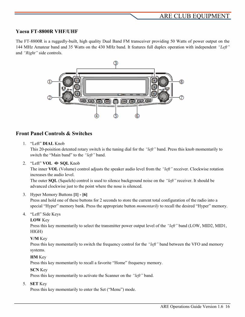
Yaesu FT-8800R VHF/UHF
The FT-8800R is a ruggedly-built, high quality Dual Band FM transceiver providing 50 Watts of power output on the
144 MHz Amateur band and 35 Watts on the 430 MHz band. It features full duplex operation with independent “Left”
and “Right” side controls.
Front Panel Controls & Switches
1. “Left” DIAL Knob
This 20-poisition detented rotary switch is the tuning dial for the “left” band. Press this knob momentarily to
switch the “Main band” to the “left” band.
2. “Left” VOL SQL Knob
The inner VOL (Volume) control adjusts the speaker audio level from the “left” receiver. Clockwise rotation
increases the audio level.
The outer SQL (Squelch) control is used to silence background noise on the “left” receiver. It should be
advanced clockwise just to the point where the nose is silenced.
3. Hyper Memory Buttons [1] - [6]
Press and hold one of these buttons for 2 seconds to store the current total configuration of the radio into a
special “Hyper” memory bank. Press the appropriate button momentarily to recall the desired “Hyper” memory.
4. “Left” Side Keys
LOW Key
Press this key momentarily to select the transmitter power output level of the “left” band (LOW, MID2, MID1,
HIGH)
V/M Key
Press this key momentarily to switch the frequency control for the “left” band between the VFO and memory
systems.
HM Key
Press this key momentarily to recall a favorite “Home” frequency memory.
SCN Key
Press this key momentarily to activate the Scanner on the “left” band.
5. SET Key
Press this key momentarily to enter the Set (“Menu”) mode.
ARE CLUB EQUIPMENT

17 | ARE Operations Guide Version 1.6
6. “Right” Side Keys
LOW Key
Press this key momentarily to select the transmitter power output level of the “Right” band (LOW, MID2,
MID1, HIGH)
V/M Key
Press this key momentarily to switch the frequency control for the “Right” band between the VFO and memory
systems.
HM Key
Press this key momentarily to recall a favorite “Home” frequency memory.
SCN Key
Press this key momentarily to activate the Scanner on the “Right” band.
7. “Right” VOL SQL Knob
The inner VOL (Volume) control adjusts the speaker audio level from the “Right” receiver. Clockwise rotation
increases the audio level.
The outer SQL (Squelch) control is used to silence background noise on the “Right” receiver. It should be
advanced clockwise just to the point where the nose is silenced.
8. “Right” DIAL Knob
This 20-poisition detented rotary switch is the tuning dial for the “Right” band. Press this knob momentarily to
switch the “Main band” to the “Right” band.
Basic Operation
1. Turning the Transceiver On and Off
Press and hold the “right” VOL knob for 2 seconds.
2. Adjusting the Audio Volume Level
The audio volume level is set independently for the “left” and “right” sides of the transceiver. The “left” VOL
knob provides adjustment for the “left” side while the “right” VOL knob provides adjustment for the “right”
side.
3. Adjusting the Squelch Setting
The squelch is set independently for the “left” and “right” sides of the transceiver. The “left” SQL knob
provides adjustment for the “left” side while the “right” SQL knob provides adjustment for the “right” side.
4. Selecting the Operating Band
The “Main” band frequency on which transmission is possible will be indicated by the icon. To establish
the “Main” band, simply press the DIAL knob for the “left” or “right” side momentarily. You will observe
the icon lighting up alternate sides of the display as you switch “Main” bands from the “left” side to the
“right” side.
5. Selecting a Transmitting Channel.
The ARE Club radios are pre-programmed with all the necessary frequency channels needed for operations.
Press the V/M key momentarily to enter the Memory Mode.
Rotate the DIAL knob to select the desired channel.
See the appendix for a complete list of programmed channels.
ARE CLUB EQUIPMENT

ARE Operations Guide Version 1.6 18
Frequency Navigation
1. Tuning Dial
Rotating the DIAL knob allows tuning in the pre-programmed steps established for the VFO frequency. Clock-
wise rotation of the DIAL knob causes the FT-8800R to be tuned toward a higher frequency, while counter-
clockwise rotation will lower the operating frequency.
On the “Main” band frequency, press the DIAL knob momentarily, then rotate the DIAL knob, to change the
“Main” band frequency steps to 1 MHz per step. This feature is extremely useful for making rapid frequency
excursion over the wide tuning range of the FT-8800R.
2. Direct Keypad Frequency Entry
The keypad of the microphone may be used for direct entry of the “Main” band operating frequency.
To enter a frequency from the microphone keypad, just press the numbered digits in the proper sequence.
Repeater Operations
The FT-8800R has been configured at the factory for the US repeater shifts. The 144 MHz shift will be 600 kHz and the
70 cm shift will be 5 MHz. Depending on the part of the band in which you are operating, the repeater shift may be ei-
ther downward (-) or upward (+), and one of these icons will appear at the top of the LCD when repeater shifts have
been enabled.
CTCSS Operation
Many repeater systems require that a very-low-frequency audio tone be superimposed on your FM carrier in order to
activate the repeater. This helps prevent false activation of the repeater by spurious signals from other transmitters. This
tone system, called the “CTCSS” (Continuous Tone Coded Squelch System), is included in the FT-8800R.
1. Press the [SET] key momentarily to enter the Set mode.
2. Rotate the “Main” band DIAL knob to select Menu #41 (TONE M).
3. Press the “Main” band DIAL knob momentarily, then rotate the “Main” band DIAL knob so that “ENC.DEC”
appears on the display; this activates the CTCSS Encoder, which allow repeater access.
4. When you have made your selection of the CTCSS tone mode, press the “Main” band DIAL knob momentarily,
then rotate the “Main” band DIAL knob one click counter-clockwise to select Menu #40 (TONE F).
5. Press the “Main” band DIAL knob momentarily to enable adjustment of the CTCSS Frequency.
6. Rotate the “Main” band DIAL knob until the display indicates the Tone Frequency you need.
7. When you have made your selection, press and hold the “Main” band DIAL knob for 1/2 second to save the new
setting and exit to normal operation.
ARE CLUB EQUIPMENT

19 | ARE Operations Guide Version 1.6
Yaesu FT-897D HF/VHF/UHF
The FT-897D is multiband, multimode portable transceiver for the amateur radio MF/HF/VHF/UHF bands. Providing
coverage of the 160-10 meter bands (including the 60m band) plus the 6m, 2m, and 70cm bands, the FT-897D includes
operation on the SSB, CW, AM, FM, and digital modes.
Front Panel Controls & Switches
1. LCD Display
The LCD display indicates the operating frequency and other aspects of transceiver operation.
2. FUNC Keys
These three keys select many of the most important operating features of the transceiver. When you press the [F]
key, then rotate the MEM/VFO CH knob, the current function of that key will appear above each of the [A],
[B], and [C] keys.
3. MIC Jack
Connect the supplied Hand Microphone to this jack.
4. PHONES Jack
This 1/4-inch 3-contact jack accepts either monaural or stereo headphones.
5. POWER Switch
Press and hold the POWER switch for one second to turn to the transceiver on or off.
6. [F] Key
Press this key momentarily to enable the changing of the function of the Multi Function keys ([A], [B], and [C] )
by the MEM/VFO CH knob.
7. LOCK Key
Pressing this key locks the front panel keys to prevent accidental frequency change.
8. MAIN DIAL
This is the main tuning dial for the transceiver.
9. AF Knob
The (inner) VOL knob adjusts the receiver audio volume lever.
ARE CLUB EQUIPMENT

ARE Operations Guide Version 1.6 20
10. SQL/RF Knob
Adjusts the gain of the receiver’s RF and IF stages. It can be changed to Squelch control via menu selections.
11. CLAR/IF SHIFT Key
Pressing this key activates the Receiver Clarifier feature.
12. CLAR Knob
This knob tunes the clarifier offset frequency.
13. BAND(DWN)/BAND(UP) Key
Pressing either of these keys momentarily will cause the frequency to be moved up or down by one frequency
band.
14. MEM/VFO CH Knob
This detented rotary switch is used for VFO frequency tuning, memory selection, and function selection for the
([A], [B], and [C] keys of the transceiver.
15. DSP Button
Pressing this button momentarily provides instant access to the Multi Function Row “p” (MFp), which contains
the command key for the receiver’s Digital Signal Processing system.
16. HOME Key
Pressing this key momentarily recalls a favorite “Home” frequency memory.
17. V/M Key
Pressing this key switches frequency control between VFO and Memory Systems.
18. Mode Keys
Pressing either of these keys momentarily will change the operating mode.
19. DSP Indicator
This indicator glows green when the DSP feature is activated.
20. TRANSMIT/BUSY Indicator
This indicator glows green when the squelch opens and turns red during transmission.
ARE CLUB EQUIPMENT

21 | ARE Operations Guide Version 1.6
Basic Operation
1. Turning the Transceiver On and Off
Press and hold the POWER for one second.
2. Adjusting the Audio Volume Level
Rotate the AF knob clockwise to adjust the receiver volume.
3. Changing the frequency band.
Press the BAND(DWN) or BAND(UP) key to move to the next lower or higher
operating band.
4. Changing the MODE
Press the MODE or MODE key to move among the eight setting
for operating modes.
5. Selecting a Transmitting Channel.
The ARE Club radios are pre-programmed with all the necessary frequency
channels needed for operations.
In the SSB/CW/DIG modes, rotate the Dial knob to set the frequency
In the AM/FM.PKT modes, rotate the MEM/VFO CH knob to set
the frequency.
See the appendix for a complete list of programmed channels.
ARE CLUB EQUIPMENT

ARE Operations Guide Version 1.6 22
Ameritron SDC-102 Screwdriver Antenna Controller
The SDC-102 Screwdriver Controller provides manual operation for tuning screwdriver antennas. In addition, tuned
positions can be saved in one of the 10 presets so it can be recalled later. A 4-digit counter is used to display the current
antenna position. This position is indicated by number of turns from the “parked” or 0 (zero) turns position. The number
of turns from the 0 position determines the frequency to which the antenna is tuned.
ARE CLUB EQUIPMENT
23 | ARE Operations Guide Version 1.6
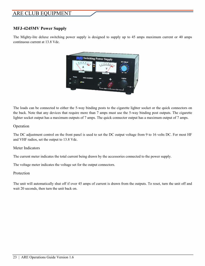
MFJ-4245MV Power Supply
The Mighty-lite deluxe switching power supply is designed to supply up to 45 amps maximum current or 40 amps
continuous current at 13.8 Vdc.
The loads can be connected to either the 5-way binding posts to the cigarette lighter socket or the quick connectors on
the back. Note that any devices that require more than 7 amps must use the 5-way binding post outputs. The cigarette
lighter socket output has a maximum outputs of 7 amps. The quick connector output has a maximum output of 7 amps.
Operation
The DC adjustment control on the front panel is used to set the DC output voltage from 9 to 16 volts DC. For most HF
and VHF radios, set the output to 13.8 Vdc.
Meter Indicators
The current meter indicates the total current being drawn by the accessories connected to the power supply.
The voltage meter indicates the voltage set for the output connectors.
Protection
The unit will automatically shut off if over 45 amps of current is drawn from the outputs. To reset, turn the unit off and
wait 20 seconds, then turn the unit back on.
ARE CLUB EQUIPMENT

ARE Operations Guide Version 1.6 24
Portable Go Box
The club maintains 2 portable stations or “Go Boxes”. These are designed to be transported and setup at any remote site.
The boxes include the following equipment:
Yaesu FT-8800R VHF/UHF Transceiver
Yaesu FT-897D HF/VHF/UHF Transceiver
Ameritron SDC-102 Screwdriver Antenna Controller
MFJ-4245MV Power Supply
Rig Runner
Little Tarheel II Screwdriver Antenna with Tripod
Mag-mount VHF/UHF Antenna
25’ Coax
Extension Cord
User Manuals / Nifty Manual
Euless Operations Guide
Copy of Club License
Setup Guide
Flashlight
Pen, Pencil, Paper
ARE CLUB EQUIPMENT

25 | ARE Operations Guide Version 1.6
Portable Go-Box Setup Procedure
1. Set up the box in a dry protected area if possible.
2. Remove the front and back lids.
3. Install the magmount antenna on the top of the box and connect it to the FT-8800R transceiver.
4. Setup the Tarheel antenna and tripod away from the primary operating location.
5. Connect the coax to the antenna and to the HF/50 MHz antenna jack on the back of the FT-897D.
6. Connect the antenna controller to the antenna with the control line.
7. Connect the controller power to the Rig Runner in the back of the box.
8. Connect the microphones to each transceiver.
9. Connect the power supply to a power source.
10. Turn on the power supply.
11. Turn on the FT-8800R.
12. Turn on the FT-897D.
13. Tune the Tarheel antenna.
ARE CLUB EQUIPMENT

ARE Operations Guide Version 1.6 26
Tarheel II Antenna Tuning Guide
1. Select desired frequency.
2. Push [F] key once momentarily.
3. Rotate MEM / VFO CH knob until Mfi is displayed left of
the scale at the bottom of the display.
4. Push B button until SWR is displayed above B button (2).
Scale is now a SWR meter.
5. Press and hold [F] key for 2 seconds. Menu mode and
menu number are now displayed at top of display.
6. Rotate MEM / VFO CH knob until Menu No. 75 is
displayed.
7. Rotate Main Dial until 5 is displayed. Transmitter is now
set to 5 watts.
8. Push and hold [F] until display changes.
9. Change mode to AM by pressing a mode button until AM
is displayed.
10. Transmit continuous carrier by pushing and holding mike
key.
11. Watch scale at display bottom for SWR reading.
12. Use the Ameritron SDC-102 controller to move antenna up
or down from approximate frequency turns.
13. Change number of turns until SWR is lowest (as far left as
possible) and HSWR is not displayed.
14. Stop transmitting by releasing mike key.
15. Press and hold [F] key for 2 seconds. Menu mode and
menu number now displayed at top of display.
16. Rotate MEM / VFO CH knob until Menu No. 75 is
displayed.
17. Rotate Main Dial until 100 is displayed. Transmitter is
now set to 100 watts.
18. Push and hold [F] until display changes.
19. Antenna is now tuned to displayed frequency.
ARE CLUB EQUIPMENT

27 | ARE Operations Guide Version 1.6

EMERGENCY OPERATIONS
29 | ARE Operations Guide Version 1.6
Preparedness
Being prepared for an emergency involves learning as much as you can and making plans to act. Continue to educate
yourself by keeping up with current training at the appropriate levels. Each club member should be prepared to activate
and participate in emergency events within their own abilities and/or willingness.
The City of Euless has published a Citizens Preparedness Guide with additional information. The guide is available at
www.w5eul.com/docs/prepared.pdf
Euless Police Department Emergency Operations Center
The Emergency Operations Center (EOC) has been established to provide a centralized location for the city department
heads to meet and coordinate activities during an emergency event. During these activations, access is restricted to
authorized personnel.
Tarrant County RACES
Radio Amateur Civil Emergency Service (RACES) is a volunteer organization of licensed amateur radio operators who
provide communications to affiliated government agencies during emergencies. The Federal Communications
Commission (FCC) regulates RACES under Title 47 Code of Federal Regulations (CFR), Part 97, subparts F and was
originally sponsored by the Federal Emergency Management Agency (FEMA). FEMA has turned over administration of
RACES to the individual states and local jurisdictions. The City of Fort Worth, as part of a contract with Tarrant County,
manages the RACES program for Tarrant County. The RACES Liaison officer is a funded position of the Fort Worth
Office of Emergency Management.
Amateur Radio Emergency Service (ARES) is a group of FCC-licensed amateur radio operators who volunteer their
services and equipment to public or private agencies during emergencies. ARES operates under the auspices of the
American Radio Relay League (ARRL), a national, not-for-profit organization, which is now a recognized affiliate
program with the Department of Homeland Security’s Citizen Corps initiative. ARES is also a member of the National
Voluntary Organizations Active in Disasters (NVOAD). In the North Texas ARRL Section, the Section Emergency
Coordinator appoints Emergency Coordinators (EC) on a county wide basis. The EC for Tarrant County is traditionally
the same as the RACES Liaison officer.
These two groups working in concert provide various emergency communications functions using volunteer radio
amateur operators as a service to the citizens of Tarrant County.
The mission of Tarrant County RACES:
1. Provide Skywarn trained, amateur radio operators, (spotters), when activated by the National Weather Service.
These spotters will obtain and disseminate severe weather observations, warnings and other “ground truths” to the
National Weather Service, Emergency Management, and other served agencies, using designated amateur radio
communications nets on a county wide basis.
2. Provide trained and vetted amateur radio operators to provide communications and support functions when
requested by the Fort Worth - Tarrant County Office of Emergency Management in support of any mission
The mission of Tarrant County ARES:
1. To serve as a key coordinating point for amateur radio operators in Tarrant county who want to volunteer their
equipment, knowledge, experience, and other resources in an emergency or public service event.
EMERGENCY OPERATIONS

ARE Operations Guide Version 1.6 30
Goals of Tarrant County RACES and ARES®
1. To establish close cooperative relationships with relevant organizations and agencies within Tarrant and
adjoining counties.
2. To be recognized as the "go-to" group for community organizations needing communication support for events
and activities of general benefit to the community. These “Public Service” events are used as training and skills
improvement exercises in times of non-emergency.
3. To be recognized by emergency services agencies and the amateur community alike as a model of competence
and professionalism in operations.
4. Foster the development of skills and capabilities that will keep the organization and its members abreast of new
technologies to help support the communication needs of served agencies.
5. To use the resources of the group members and their involvement in community activities to foster awareness of
the need for preparedness in the community at large.
6. Develop continuing and ongoing education in order to exercise member’s equipment and capabilities year-
round.
7. Insure that expectations of the members and leaders are clearly understood and that basic levels of skills and
performance required in emergency conditions of different types will be available.
8. Emphasize professionalism and “Esprit de corps” in every interaction with the general public and served
agencies.
9. Recruit new members in order to maintain and expand the necessary capabilities for both organizations.
1 noun: A spirit of solidarity; a sense of pride, devotion, and honor among the members of a group.
EMERGENCY OPERATIONS

31 | ARE Operations Guide Version 1.6
ARE Club Activation
Euless Office of Emergency Management can activate for disasters within the city limits of Euless as needed. The Euless
EOC will use the City of Euless mass communications system to alert ARE members for an activation.
Activation for severe weather will be requested by the National Weather Service office in Fort Worth.
Communications Equipment
Each club member should maintain a Basic Communications Go-Kit for use during an activation. See the appendix for a
recommended Go-Kit inventory list.
Tarrant County RACES has adopted the EmComm standardized frequency list published by the DFW Area Ham Radio
Interoperability Group. This template insures members have the basic set of frequencies to support emergency
communications. For more details go to www.dfwhrig.org. ARE has adopted this template as our standard all club
radios. We recommend that you program your radios to this standard.
Programming files for several brands of radios are available on the club website at www.w5eul.com.
For details, see the Frequency Plan section in the appendix of this guide.
Euless Community Emergency Response Team
CERT is an initiative of the Police and Fire Departments to ensure that our community is informed and prepared in the
event of a disaster. CERT teams are invaluable to a community and will improve the City of Euless' community
emergency preparedness. CERT members assist others in their neighborhood or workplace following an event when
professional responders are not immediately available to help. They also support emergency response agencies by taking
active roles in emergency preparedness projects in their community.
The CERT Program educates people about disaster preparedness for hazards that may impact their area and trains them
in basic disaster response skills, such as fire safety, light search and rescue, team organization, and disaster medical
operations.
ARE works closely with the Euless CERT teams by providing communications support. ARE club members should have
at least one FRS radio for use during CERT operations.
For details of FRS Radio channel assignments, please see the Frequency Plan section in the appendix of this
guide.
EMERGENCY OPERATIONS

ARE Operations Guide Version 1.6 32
RACES Skywarn Spotter Net
During severe weather events, the National Weather Service may request an activation of Tarrant County RACES
Skywarn spotter net. This is a directed net open to RACES members only. The mission of this net is to provide “Ground
Truth” reporting on the current weather conditions.
RACES Frequency List
(All repeaters use 110.9 Hz PL® tone. During RACES Nets you will hear Dit-Dah-Dit “R” as courtesy beep)
Primary Repeater 146.940 Mhz**
Backup Repeater 146.760 Mhz
Southeast 147.140 Mhz
Southwest 146.680 Mhz
Northeast 147.100 Mhz
Northwest 145.110 Mhz
Primary UHF 444.100 Mhz
Wide Area UHF 442.400 Mhz
** Monitored by NWS, RACES members should monitor and report on this repeater for all Weather Activations
Reporting Criteria
Winds greater than 50 MPH
Hail larger than 3/4 inch in diameter. (Penny)
Wall clouds / Tornados / Wind Caused Damage
Flooding impacting homes or making streets and highways impassable
Conditions which impact life and safety of the public
Standard Reporting Format
Who are you? (Your Call/Tactical Call)
Where are you? (Major Mapsco® Grid or Major Cross Streets )
Wind Direction and Speed ? (Each time you report)
What size of hail and intensity ?
Any other important information?
Your full amateur call sign
Hail Size Reporting
Penny .75 Inch
Nickel 7/8 Inch
Quarter 1 Inch
Half Dollar 1.25 Inch
Golf Ball 1.75 Inch
Tennis Ball 2.5 Inch
Baseball 3.5 Inch
Softball 4.5 Inch
EMERGENCY OPERATIONS

33 | ARE Operations Guide Version 1.6
Estimating Wind Speeds (Beaufort Wind Scale)
EMERGENCY OPERATIONS
Wind Speed Estimation
(MPH)
Description
25 - 31 Large branches in motion; whistling heard in telephone wires
32 - 38 Whole trees in motion; inconvenience felt walking against the wind
39 - 46 Breaks twigs off trees; wind generally impedes progress
47 - 54 Slight structural damage occurs
55 - 63 ** Damage to chimneys and TV antennas; pushes over shallow rooted
trees
50 - 58 ** Small branches or limbs broken (less than 2" diameter)
58 - 70 ** Large limbs knocked down, the size of an adult's wrist; power lines
knocked down; a few house shingles torn off.
70 - 80 ** A few small trees or shrubs can be uprooted; Very large branches bro-
ken off, Barns may sustain considerable damage.
> than 80 ** Trees may be uprooted or snapped, power poles snapped or knocked
over; Large vehicles can be blown off the road. Roofs blown off homes.

ARE Operations Guide Version 1.6 34
EMERGENCY OPERATIONS

35 | ARE Operations Guide Version 1.6
Tornado Safety Tips
If a Warning is issued or if threatening weather approaches:
In a home or building, move to a pre-designated shelter, such as a basement.
If an underground shelter is not available, move to an interior room or hallway on the lowest floor and get under
sturdy piece of furniture.
Stay away from windows.
Get out of automobiles.
Do not try to outrun a tornado in your car; instead, leave it immediately.
Do not use bridges or overpasses for shelter from tornadoes.
Mobile homes, even if tied down, offer little protection from tornadoes and should be abandoned.
Occasionally, tornadoes develop so rapidly that advanced warning is not possible. Remain alert for signs of an
approaching tornado.
Flying debris from tornadoes causes most deaths and injuries.
Flash Flood Safety
When a “Flash Flood Warning” is issued for your area, or the moment you realize that a flash flood is imminent, act
quickly to save yourself. You may have only seconds!
Get out of area subject to flooding. These include dips, low spots, canyons, washes and the like.
Avoid already flooded and high velocity flow areas. Do not attempt to cross flowing streams.
If driving, be aware that the road bed may not be intact under flood waters. Turn around and go another way.
NEVER drive through flooded roadways!
If the vehicle stalls, leave it immediately and seek higher ground safely if you can. Rapidly rising water may
engulf the vehicle and its occupants and sweep them away. Remember, it’s better to be wet than dead!
Be especially cautious at night when it is harder to recognize flood dangers.
Do not camp or park your vehicle along streams and washes, particularly during threatening conditions.
Severe Thunderstorm and Lightning Safety
Severe thunderstorms are dangerous environments:
If you can hear thunder, you are close enough to the storm to be struck by lightning. Go to safe shelter
immediately!
Move to a sturdy building and stay away from windows. Do not take shelter in small sheds, under isolated trees,
or in convertible automobiles.
If sturdy shelter is not available, get inside a hard top automobile and keep windows up. Beware, though, since
vehicles offer poor protection from downburst winds and only fair protection from hail.
Get out of boats and away from water. Unplug appliances not necessary for obtaining weather information. Avoid
using the telephone or any electrical appliances. Use landline phones ONLY in an emergency.
If caught outdoors and no shelter is nearby:
Find a low spot away from trees, fences, and poles. Make sure the place you pick is not subject to flooding.
If you are in the woods, take shelter under the shorter trees.
If you feel your skin tingle, or your hair stand on end. Squat low to the ground on the balls of your feet. Make
yourself the smallest target possible, and minimize contact with the ground.
If you are boating or swimming, get to land and find shelter immediately!
EMERGENCY OPERATIONS

ARE Operations Guide Version 1.6 36
Spotter Glossary
Anvil – The flat, spreading top of a cumulonimbus cloud. Often shaped like an anvil.
Beaver(‘s) Tail – An inflow band with a relatively broad, flat appearance suggestive of a beaver’s tail. It is attached to a
supercell’s updraft and is oriented roughly east to west.
BLMRS -- The BLMRS card is RACES’ equivalent to the NIMS Resource Status Card. It is used at staging to record
incoming communicator contact information, resource capability, and to log assignment activity. The card provides the
staging manager a tool to manage available and assigned resources, their status, and location.
Clear Slot – A local region of clearing skies or reduced cloud cover indicating an intrusion of drier air. Often seen on
the west or southwest side of a wall cloud and believed to be a visual indication of a rear flank downdraft.
Cumuliform – Has the appearance of a cumulus cloud, a solid and lumpy or cauliflower-like appearance. Cumuliform
towers are often associated with strong updrafts.
Downburst – A strong downdraft resulting in an outward burst of damaging winds on or near the ground. Sometimes
referred to as “straight-line winds.” Downbursts can produce damage similar to a strong tornado.
Downdraft – A small-scale column of air that rapidly sinks toward the ground. Usually accompanied by precipitation as
in a shower or thunderstorm.
Elevated Reporting Criteria – Net Control Stations will call for elevated reporting criteria for significant reports such
as rotating lowerings, rotating funnels, flashes of light at ground level not associated with lightning, tornados or other
immediate threats to life or property. When Elevated Reporting Criteria is in effect on a SKYWARN Net, stations with
only Minimum or Modified Reporting Criteria should hold their reports.
Flanking Line – A line of cumulus or towering cumulus clouds connected to and extending outward from the most
active part of a supercell. Normally extends to the southwest of the main storm tower.
Flash Flooding -- A rapid and extreme flow of high water into a normally dry area or a rapid water level rise in a stream
or creek above a predetermined flood level, beginning within six hours of the causative event (e.g., intense rainfall, dam
failure, ice jam). However, the actual time threshold may vary in different parts of the country. Ongoing flooding can
intensify to flash flooding in cases where intense rainfall results in a rapid surge of rising flood waters.
Funnel Cloud – A condensation funnel extending from the base of a towering cumulus or cumulonimbus. Associated
with a rotating column of air that is not in contact with the ground.
Glaciated – Having the appearance of a cirrus cloud. Thin in fibrous in appearance. Glaciated clouds are associated with
the tops of thunderstorms, especially those with weaker updrafts.
Gust Front – The leading edge of gusty surface winds from thunderstorm downdrafts. Sometimes associated with a
shelf or roll cloud.
High Precipitation (HP) Supercell – A supercell with a large amount of visible precipitation encircling the
mesocyclone. HP supercells can be difficult to observe visually, as the precipitation often obscures the updraft related
cloud features.
Inflow Bands – Bands of low clouds, arranged parallel to the low-level winds and moving into or toward a
thunderstorm. They may indicate the strength of the inflow of moist air into the storm, and hence, its potential severity.
EMERGENCY OPERATIONS

37 | ARE Operations Guide Version 1.6
Landspout – A tornado that does not arise from organized storm-scale rotation and, therefore, is not associated with a
wall cloud or a mesocyclone. Low Precipitation (LP) Supercell – A supercell with little visible precipitation falling from
it. LP supercells often have flared-out updraft towers with striations, thus, they are easy to recognize visually. However,
they can be difficult to detect on radar.
Mammatus Clouds – Rounded, smooth, sack-like protrusions hanging from the underside of a thunderstorm anvil.
Mammatus clouds often accompany severe thunderstorms, but do not produce severe weather.
Mesocyclone – A storm-scale region of rotation, typically around two to six miles in diameter and often found in the
right rear flank of a supercell, or on the front flank of an HP storm.
Minimum Reporting Criteria – The standard criteria required for reporting weather events on a DFW Area RACES
SKYWARN Net. Defined as being equal to or greater than any of the following: Ffash flooding, wind greater than fifty
miles per hour (50 MPH), or hail one inch (1”) or larger. Events that do not meet these Minimum Reporting Criteria
should not be reported on a SKYWARN Net. Net Control Stations may institute Modified or Elevated Reporting Criteria
at the request of served agencies or in order to control or further limit Net traffic.
Modified Reporting Criteria – Net Control Stations will call for modified reporting criteria at the request of a served
agency such as the National Weather Service. Modified Reporting Criteria may be, but not limited to, events such as
wind or flooding reports with more specificity than implied in Minimum Reporting Criteria. When Modified Reporting
Criteria is in effect on a SKYWARN Net stations with Minimum Reporting Criteria may continue to submit their
reports.
Multiple-vortex Tornado – A tornado in which two or more condensation funnels or debris clouds are present, often
rotating about a common center or about each other.
Overshooting Top – A dome-like protrusion above a thunderstorm anvil, representing a very strong updraft and hence a
higher potential for severe weather with that storm.
Power Flash – A blue-green flash caused by the arcing of electric power lines. They are often a visual indication of
damaging winds.
Rain Foot – A horizontal building near the surface in a precipitation shaft, forming a foot-shaped prominence. A rain
foot is a visual indication of a wet microburst.
Rain-free Base – A dark, horizontal cloud base with no visible precipitation beneath it. The rain-free base typically
marks the location of the thunderstorm updraft.
Rear Flank Downdraft – A region of sinking dry air on the back side of, and wrapping around a mesocyclone. The
RFD is often visible as a clear slot wrapping around the wall cloud.
Roll Cloud – A low, horizontal tube-shaped cloud associated with a thunderstorm gust front.
Scud – Small, ragged, low cloud fragments that are unattached to a larger cloud base and often seen with and behind
thunderstorm gust fronts. Scud clouds generally are associated with cool moist air, such as thunderstorm outflow.
Severe Thunderstorm – A thunderstorm which produces tornadoes, hail 0.75 inches or more in diameter, or winds of
50 knots (58 MPH) or more. Structural wind damage may imply the occurrence of a severe thunderstorm.
Shelf Cloud – A low, horizontal wedge-shaped arcus cloud, associated with a thunderstorm gust front. The shelf cloud
is attached to the base of the parent cloud above it.
EMERGENCY OPERATIONS

ARE Operations Guide Version 1.6 38
Squall Line – A solid, or nearly solid line or band of active thunderstorms.
Striations – Groves or channels in cloud formations, arranged parallel to the flow of air and therefore depicting the
airflow relative to the parent cloud. Striations often reveal the presence of rotation, as in the barber pole or “corkscrew”
effect often observed with a rotating updraft.
Supercell – A thunderstorm with a persistent rotating updraft. Supercells are rare, but are responsible for a remarkably
high percentage of severe weather events, especially tornadoes, extremely large hail, and damaging straight-line winds.
Tail Cloud – A horizontal, tail-shaped cloud (not a funnel cloud) at low levels extending from the precipitation region of
a supercell toward the wall cloud.
Tornado – A violently rotating column of air in contact with the ground and extending from the base of a thunderstorm.
Tower Cumulus – A large cumulus cloud with great vertical development, usually with a cumuliform or cauliflower-
like appearance, but lacking the characteristic anvil of a cumulonimbus.
Updraft – A small-scale column of rising air.
Virga – Precipitation which falls from a cloud base but evaporates before reaching the ground. Virga often has a streaky
or stringy appearance as it hangs down from the cloud base.
Wall Cloud – A rotating, localized, persistent, often abrupt lowering from a rain-free base. Wall clouds can range from
a fraction of a mile in diameter, up to nearly five miles in diameter and are normally found on the south or southwest
side of the thunderstorm.
EMERGENCY OPERATIONS

39 | ARE Operations Guide Version 1.6
Heat Index Chart
Hot – Heat stroke, heat cramps or heat exhaustion possible with prolonged exposure or physical activity.
Very Hot – Heat cramps or heat exhaustion likely and heat stroke possible with prolonged exposure and physical
activity.
Extremely Hot – Heat stroke likely with continued exposure.
Wind Chill Index
EMERGENCY OPERATIONS

APPENDIX

41 | ARE Operations Guide Version 1.6
Frequency Plans
Euless CERT Team FRS Radio Assignments
Please note that FRS radios should be set to Privacy Code 21
Privacy Codes CTCSS Tones in Hz
APPENDIX
Channel # Frequency Assignment
1 462.5625 Neighborhood Watch to Responders
2 462.5875 CERT Team Leaders to Command
3 462.6125 CERT Planning Section
4 462.6375 CERT Logistics Section
5 462.6625 CERT Admin Section
6 462.6875 CERT Team Leader to Public Safety
7 462.7125 Safety Officer
8 467.5625 CERT OPS inter-Team Primary Channel
9 467.5875 RED Team
10 467.6125 GREEN Team
11 467.6375 WHITE Team
12 467.6625 ORANGE Team
13 467.6875 BLUE Team
14 467.7125 BROWN Team
FRS 1 67.0 FRS 14 107.2 FRS 27 167.9
FRS 2 71.9 FRS 15 110.9 FRS 28 173.8
FRS 3 74.4 FRS 16 114.8 FRS 29 179.9
FRS 4 77.0 FRS 17 118.8 FRS 30 186.2
FRS 5 79.7 FRS 18 123.0 FRS 31 192.8
FRS 6 82.5 FRS 19 127.3 FRS 32 203.5
FRS 7 85.4 FRS 20 131.9 FRS 33 210.7
FRS 8 88.5 FRS 21 136.5 FRS 34 218.1
FRS 9 91.5 FRS 22 141.3 FRS 35 225.7
FRS 10 94.8 FRS 23 146.2 FRS 36 223.6
FRS 11 97.4 FRS 24 151.4 FRS 37 241.8
FRS 12 100.0 FRS 25 156.7 FRS 38 250.3
FRS 13 103.5 FRS 26 162.2

ARE Operations Guide Version 1.6 42
Tarrant County Standard Emcomm template
APPENDIX
Location Name Frequency Tone Comments Location Name Frequency Tone Comments
1 FTW PRI 146.94 110.9 RACES PRIM 38 TA6760 146.76 110.9
2 FTW BU 146.76 110.9 RACES BACK 39 WS6780 146.78 131.8 DECATU
3 FTW SW 146.68 110.9 RACES SW 40 HU6780 146.78 114.8 Hunt-V
4 FTW SE 147.14 110.9 RACES NE 41 DA6880 146.88 110.9 Dal-Pri
5 FTW NE 147.1 110.9 RACES SE 42 DN6920 146.92 110.9 Den-Pri
6 FTW NW 145.11 110.9 RACES NW 43 TA6940 146.94 110.9 Ftworth
7 FTW UHF 444.1 110.9 RACES UHF 44 DA6960 146.96 110.9 Dal-Sec
8 FTW WIDE 442.4 110.9 CedarHill 45 KF6980 146.98 88.5
9 FTW ALT1 146.84 110.9 RACES ALT 1 46 WS6980 146.98 192.8 BOYD
10 FTW ALT2 147.28 110.9 RACES ALT 2 47 GS7000 147 100 Gray-Pri
11 FTW TMS 444.1 100.0 RACES TMS 48 DA7040 147.04 136.5 Mesquite
12 FTW VAN1 444.1 103.5 OLD VAN 49 PR7040 147.04 110.9
13 FTW VAN2 444.1 118.8 NEW VAN 50 TA7100 147.1 110.9
14 REDCROS 147.42 146.2 Red Cross 51 DA7120 147.12 100 Rich
15 EOCBU 443.875 110.9 EOCBU 52 TA7140 147.14 110.9 E-TARRA
16 2M Call 146.52 N/A VHF Call 53 CI7180 147.18 107.2 PARK VHF
17 70 Call 446.00 N/A UHF Call 54 GS7220 147.22 100 COLLINSV
18 Euless 442.9 110.9 UHF Repeater 55 GS7280 147.28 107.2 Gray-Sec
19 EUL SV 146.55 N/A VHF Simplex 75 DN7380 147.38 110.9 LAARK
20 EUL SU 446.66 N/A UHF Simplex 76 DN1325 441.325 88.5 Denton
21 TA5110 145.11 110.9 NW-TARRA 77 RW1525 441.525 141.3 Rock-U
22 DN5170 145.17 110.9 Den-Sec 78 DA1925 441.925 110.9 W5EBQ
23 DA5190 145.19 110.9 KA5CTN 79 DA2400 442.4 110.9 CedarHil
24 DA5210 145.21 110.9 MARS 80 DA2625 442.625 110.9 Mesquite
25 DA5310 145.31 110.9 Mesquite 81 DA2650 442.65 110.9 Carrollt
26 CI5350 145.35 100 N5GI 82 DA2700 442.7 110.9 GARLAND
27 EL541E 145.41 110.9 83 CO2775 442.775 100 GAINESVI
28 FN5470 145.47 88.5 Fannin 84 DA2800 442.8 110.9 UTD
29 CK5490 145.49 85.4 85 CI3200 443.2 100 MERA UHF
30 JN5490 145.49 88.5 86 PR3250 443.25 110.9
31 HU5490 145.49 167.9 COMMERCE 87 DN3525 443.525 118.8 Denton
32 DA6640 146.64 118.8 K5AHT 88 DA4025 444.025 110.9 WX5O
33 DA6660 146.66 110.9 Garland 89 DN4050 444.05 110.9 DENTON
34 TA6680 146.68 110.9 SW-TARRA 90 DA4075 444.075 110.9 CARROLLT
35 DA6700 146.7 110.9 W5EBQ 91 TA4100 444.1 110.9
36 DA6720 146.72 110.9 Irving 92 CI4250 444.25 79.7 PARK UHF
37 CI6740 146.74 110.9 MARC 93 GS4750 444.75 100 Grayson UHF

43 | ARE Operations Guide Version 1.6
ARES® HF Net Frequencies
North Texas Section ARES®
3860 KHz LSB for evening and night operations
7277.5 KHz LSB for morning and day operations
Texas ARES®
3872 KHz LSB for evening and night operations
7285 KHz LSB for morning and day operations
APPENDIX
Location Name Frequency Tone Comments Location Name Frequency Tone Comments
100 CI45125 444.5125 123 Celina 121 WIN910 144.91 WIN910
101 145.46 145.46 145.46 123 WIN930 144.93 WIN930
102 145.6 145.6 145.6 124 WIN950 144.95 WIN950
103 145.7 145.7 145.7 125 WIN970 144.97 WIN970
104 146.4 146.4 146.4 126 WIN990 144.99 WIN990
105 146.48 146.48 146.48 127 WIN010 145.01 WIN010
106 146.5 146.5 146.5 128 WIN030 145.03 WIN030
107 146.52 146.52 146.52 129 WIN050 145.05 WIN050
108 146.54 146.54 146.54 130 WIN070 145.07 WIN070
109 146.56 146.56 146.56 131 WIN090 145.09 WIN090
110 146.58 146.58 146.58 132 APRS-SEC 144.34 APRS-SEC
111 147.42 147.42 147.42 133 APRS-PRI 144.39 APRS-PRI
112 147.44 147.44 147.44 134 444.6 444.6 444.6
113 147.51 147.51 147.51 135 445 445 445
114 147.52 147.52 147.52 136 445.5 445.5 445.5
115 147.55 147.55 147.55 137 446.1 446.1 446.1
116 147.56 147.56 147.56 138 446.5 446.5 446.5
120 147.58 147.58 147.58 139 447 447 447
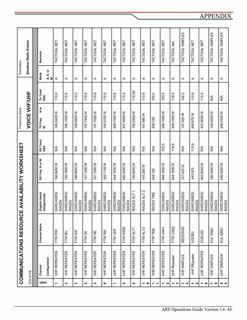
ARE Operations Guide Version 1.6 44
APPENDIX
CO
MM
UN
ICA
TIO
NS
RE
SO
UR
CE
AV
AIL
AB
ILIT
Y W
OR
KS
HE
ET
ICS
217A
Fre
qu
ency B
and
VO
ICE
VH
F/U
HF
Descri
ptio
n
Am
ate
ur
Rad
io E
ule
ss
HRIG
Ch
an
nel
Co
nfi
gu
rati
on
Ch
an
nel N
am
e
Elig
ible
Us
ers
/
Assig
nm
en
ts
RX
Fre
q N
or
W
RX
To
ne/
NA
C
TX
Fre
q
N o
r
W
Tx T
on
e/
NA
C
Mo
de
A,
D.
or
M
Rem
ark
s
1
VH
F R
EP
EA
TE
R
FT
W P
RI
EA
RC
/AR
ES
/
RA
CE
S
146.9
400 W
N
/A
146.3
400 W
110.9
A
TA
CT
ICA
L N
ET
2
VH
F R
EP
EA
TE
R
FT
W B
U
EA
RC
/AR
ES
/
RA
CE
S
146.7
600 W
N
/A
146.1
600 W
110.9
A
TA
CT
ICA
L N
ET
3
VH
F R
EP
EA
TE
R
FT
W S
W
EA
RC
/AR
ES
/
RA
CE
S
146.6
800 W
N
/A
146.0
800 W
110.9
A
TA
CT
ICA
L N
ET
4
VH
F R
EP
EA
TE
R
FT
W S
E
EA
RC
/AR
ES
/
RA
CE
S
147.1
400 W
N
/A
147.7
400 W
110.9
A
TA
CT
ICA
L N
ET
5
VH
F R
EP
EA
TE
R
FT
W N
E
EA
RC
/AR
ES
/
RA
CE
S
147.1
000 W
N
/A
147.7
000 W
110.9
A
TA
CT
ICA
L N
ET
6
VH
F R
EP
EA
TE
R
FT
W N
W
EA
RC
/AR
ES
/
RA
CE
S
145.1
100 W
N
/A
144.5
100 W
110.9
A
TA
CT
ICA
L N
ET
7
UH
F R
EP
EA
TE
R
FT
W U
HF
EA
RC
/AR
ES
/
RA
CE
S
444.1
000 W
N
/A
449.1
000 W
110.9
A
TA
CT
ICA
L N
ET
8
UH
F R
EP
EA
TE
R
FT
W W
IDE
EA
RC
/AR
ES
/
RA
CE
S
442.4
000 W
N
/A
447.4
000 W
110.9
A
TA
CT
ICA
L N
ET
9
VH
F R
EP
EA
TE
R
FT
W A
LT
1
RA
CE
S A
LT
1
146.8
400 W
N
/A
146.2
400 W
110.0
9
A
TA
CT
ICA
L N
ET
1 0
VH
F R
EP
EA
TE
R
FT
W A
LT
2
RA
CE
S A
LT
2
147.2
80 W
N
/A
147.8
80 W
110.9
A
T
AC
TIC
AL N
ET
1 1
VH
R R
EP
EA
TE
R
FT
W T
MS
R
AC
ES
TM
S
444.1
00
N
/A
449.1
00
100.0
A
T
AC
TIC
AL N
ET
1 2
UH
F R
EP
EA
TE
R
FT
W V
AN
1
EA
RC
/AR
ES
/
RA
CE
S
444.1
000 W
103.5
449.1
000 W
103.5
A
TA
CT
ICA
L N
ET
1 3
UH
F R
epeate
r F
TW
VA
N2
EA
RC
/AR
ES
/
RA
CE
S
444.1
000 W
118.8
449.1
000 W
118.8
A
TA
CT
ICA
L N
et
1 4
VH
F S
IMP
LE
X
RE
DC
RO
S
EA
RC
/AR
ES
/
RA
CE
S
147.4
20 W
N
/A
147.4
20 W
146.2
A
TA
CT
ICA
L S
IMP
LE
X
1 5
UH
F R
Epeate
r E
OC
BU
E
AR
C/A
RE
S/
RA
CE
S
443.8
75
110.9
448.8
75 W
110.9
A
TA
CT
ICA
L N
ET
1 8
UH
F R
EP
EA
TE
R
EU
ELS
S
EA
RC
/AR
ES
/
RA
CE
S
442.9
000 W
N
/A
447.9
000 W
110.9
A
TA
CT
ICA
L N
ET
1 9
VH
F S
IMP
LE
X
EU
L S
IMV
EA
RC
/AR
ES
/
RA
CE
S
146.5
500 W
N
/A
146.5
500 W
N
/A
A
TA
CT
ICA
L S
IMP
LE
X
2 0
UH
F S
IMP
LE
X
EU
L S
IMU
EA
RC
/AR
ES
/
RA
CE
S
446.5
500 W
N
/A
446.5
500 W
N
/A
A
TA
CT
ICA
L S
IMP
LE
X

45 | ARE Operations Guide Version 1.6
ARES® HF Net Frequencies NOAA Frequencies
North Texas Section ARES®
3860 KHz LSB for evening and night operations
7277.5 KHz LSB for morning and day operations
Texas ARES®
3872 KHz LSB for evening and night operations
7285 KHz LSB for morning and day operations
7290 KHz LSB for Health and Welfare traffic
National Simplex Frequencies Citizens Band
2m VHF 146.52
70cm UHF 446.00
APPENDIX
Channel Frequency
1 162.4
2 162.425
3 162.45
4 162.475
5 162.5
6 162.525
7 162.55
Channel Frequency Channel Frequency
1 26.965 21 27.215
2 26.975 22 27.225
3 26.985 23 27.255
4 27.005 24 27.235
5 27.015 25 28.245
6 27.025 26 27.265
7 27.035 27 27.275
8 27.055 28 27.285
9 27.065 29 27.295
10 27.075 30 27.305
11 27.085 31 27.315
12 27.105 32 27.325
13 27.115 33 27.335
14 27.125 34 27.345
15 27.135 35 27.355
16 27.155 36 27.365
17 27.165 37 27.375
18 27.175 38 27.385
19 27.185 39 27.395
20 27.205 40 27.405
ARE Operations Guide Version 1.6 46
Club Net Script
Good Evening. This is the EULESS Amateur Radio Club’s Tuesday Night Net.
My name is: _____ and my call is: _______ I will serve as Net Control tonight.
** Before we begin, is there any Emergency or Priority Traffic needing this Frequency, if so PLEASE come now.
** hold 15 seconds.
** Hearing none, if there is any Emergency or Priority Traffic during the net please call in with BREAK BREAK
and your CALL SIGN and net control will respond.
** Hold 10 seconds.
This will be a directed net, so please use your full call sign for recognition by net control. Also please notify net control
if you need to leave the net early.
This net is called the every Tuesday at 8 p.m. CST on the W5EUL repeater located in Euless, Texas. This net in place
for Amateur radio operators to exchange knowledge; train with their radios for emergencies, and to strengthen the
Fellowship of the Euless Amateur Radio Club. All licensed amateur radio operators are cordially invited to join us.
Tonight our net will cover:
Ham News
Club Officer Comments
Tech Talk
Swap Meet
Bulletins and announcements for the net
This is: (Your call sign) ______ Euless Amateur radio net in progress.
We will shortly accept Check-ins to this net PLEASE check-in SLOWY in groups of Three with your call sign, name
and location.
** Do we have any Mobile Check-ins?
** Are there any Stations on EchoLink?
**Any other stations please check in now.
** General welcome and ask social questions to operators that checked in.
APPENDIX

47 | ARE Operations Guide Version 1.6
This is: (Your call sign) ______ Euless Amateur radio net in progress.
Ham News (Net Control provide news or asks check-ins)
Club Officer Comments ( call Club officers who checked-in)
This is: (Your call sign) ______ Euless Amateur radio net in progress.
Tech Talk ( open to check-ins for help)
Swap Meet ( open to check-ins )
Any Bulletins or Announcements for the net?
** This is the final call for check-ins from any additional stations not yet
Acknowledged by net control or for any re-checks.
Please come now.
** General welcome and ask social questions to stations
This is: (Your call sign) ______ Euless Amateur radio net in progress.
The EULESS Amateur Radio Club meets at the Euless EOC on the second Wednesday of each month at 7 p.m. Euless
Amateur Radio Club members are encouraged and invited to be Net Control of this net in the future. Inquiries for more
information regarding ham radio licensing, testing, volunteering for Net Control and the Euless Amateur Radio Club in
general may contact us at this e-mail address:
India November Foxtrot Oscar @ Whisky 5 Echo Uniform Lima dot Charlie Oscar Mike
We invite you to join the net again. We hold this net every Tuesday at 8:00 PM local time.
We had a total of ____ check-ins.
** Do we need any fill-ins?
** answer any fill-ins
Thanks goes out to all who checked in, and made the net possible.
This session of the Euless Amateur Radio Club net is now secure and the repeater is now returned to regular amateur
use.
This is: (your call sign) ____ closing the net at <TIME>. All clear
APPENDIX

ARE Operations Guide Version 1.6 48
Phonetic Alphabet
H.A.N.D.
To assist in emergency situations the following reporting format has been developed that follows the letters of the word
HAND.
H – Have – What type of emergency do you Have? Is it a fire, accident with injury, medical emergency?
A – At – You are At location? An address or distance and direction from the nearest major intersection.
N – Need – What assistance do you Need? Fire and Rescue, Police Officer, or Ambulance?
D – Details – What Details will help responders?
Details are those things that responders need to know before arriving on the scene. For instance: if there is a fire, a fuel
or chemical spill; if there are fumes; multiple victims, or other hazards for which they need to prepare? Is there a
Hazardous Material Placard on a vehicle involved in an accident. The numbers tell the responders the nature of the
material involved. Do not approach vehicles that display Hazardous Material Placards. If the placard cannot be seen
from your location, do not approach the vehicle and stay up wind if possible. Inform NCS or the emergency dispatcher if
called in via auto-patch or cell phone that there is a Hazardous Material Placard.
APPENDIX
A ALPHA N NOVEMBER A ADAM N NORA
B BRAVO O OSCAR B BOY O OCEAN
C CHARLIE P PAPA C CHARLES P PAUL
D DELTA Q QUEBEC D DAVID Q QUEEN
E ECHO R ROMEO E EDWARD R ROBERT
F FOXTROT S SIERRA F FRANK S SAM
G GOLF T TANGO G GEORGE T TOM
H HOTEL U UNIFORM H HENRY U UNION
I INDIA V VICTOR I IDA V VICTOR
J JULIET W WHISKEY J JOHN W WILLIAM
K KILO X XRAY K KING X XRAY
L LIMA Y YANKEE L LINCOLN Y YOUNG
M MIKE Z ZULU M MARY Z ZEBRA
Phonetic Alphabet
ITU Police/Fire

49 | ARE Operations Guide Version 1.6
Net Do’s and Don’ts
Clear, Concise, Accurate and Timely Communications
Remember to be brief and give Net Control or emergency dispatchers and responders an opportunity to ask vital
questions.
Silence is Golden.
APPENDIX
What to do
Listen, Listen, Listen
Think about what you will say before you
transmit
Why we do
To ensure your transmission does not interfere
with another communication
To be aware of current Net condition and
minimum reporting requirements To communicate effectively
Minimum use of air time for report
Making the call
Say the call sign or tactical call sign of the
station you are calling Followed by “this is” or “from”
The call sign or tactical call sign of the calling
station
Use of a standard procedure
To understood reliably on the first call
To be clear
Communicate
Speak clearly and with moderate speed
Use plain English, no codes
Repeat critical items for confirmation
To be understood
To be fast
To avoid confusion
For accuracy
Use phonetics
Initial call to NCS
Station identification on long exchanges
For names or words that are not easily
understood
To be clear
To be accurate
To be fast
Following standard procedure
Emergency Traffic
Use the pro-word “Break Break” for life threat-
ening emergencies or to enter a Net with
Elevated Reporting Criteria
Do not use “Break Break” for non-life
threatening situations or for non-
Elevated Reporting Criteria weather
reports Be prepared to call 911 if possible and/or
necessary
To convey emergency status of a life
threatening situation For silencing the Net and quickest response
Following a standard procedure

ARE Operations Guide Version 1.6 50
Basic Communications Go-Kit
A Go-Kit is a pre-staged collection of equipment and personal gear that you will need to perform your duties as an
Emergency Communicator in the event of an activation. Your Go-Kit should be tailored to your needs, equipment,
expected assignments, and expected length of assignments.
The Basic Communications Go-Kit should have everything you need for a short duration communications assignment.
You should be able to use this kit mobile or on foot. This kit could be used for volunteer public service events.
A 24-hour kit should provide additional items needed for an overnight assignment.
A 72-hour kit should provide additional items needed for an extended assignment of up to three days.
Basic Communications Go-Kit
RACES ID Card
2m/70c Handheld Radio
FRS Radio
High Gain Antenna
HT Speaker/Microphone,
HT Earphone
Extra Batteries for HT
HT Power Cable
HT Antenna Adapter
HT Quick Reference Guide
Flashlight w/extra batteries
Pens/Pencils
Small Notebook
Personal First Aid Kit
Personal Items as required (i.e. prescription medicine , eyewear care)
Snacks
Water
APPENDIX
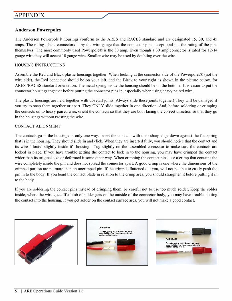
51 | ARE Operations Guide Version 1.6
Anderson Powerpoles
The Anderson Powerpole® housings conform to the ARES and RACES standard and are designated 15, 30, and 45
amps. The rating of the connectors is by the wire gauge that the connector pins accept, and not the rating of the pins
themselves. The most commonly used Powerpole® is the 30 amp. Even though a 30 amp connector is rated for 12-14
gauge wire they will accept 10 gauge wire. Smaller wire may be used by doubling over the wire.
HOUSING INSTRUCTIONS
Assemble the Red and Black plastic housings together. When looking at the connector side of the Powerpoles® (not the
wire side), the Red connector should be on your left, and the Black to your right as shown in the picture below. for
ARES /RACES standard orientation. The metal spring inside the housing should be on the bottom. It is easier to put the
connector housings together before putting the connector pins in, especially when using heavy paired wire.
The plastic housings are held together with dovetail joints. Always slide these joints together! They will be damaged if
you try to snap them together or apart. They ONLY slide together in one direction. And, before soldering or crimping
the contacts on to heavy paired wire, orient the contacts so that they are both facing the correct direction so that they go
in the housings without twisting the wire.
CONTACT ALIGNMENT
The contacts go in the housings in only one way. Insert the contacts with their sharp edge down against the flat spring
that is in the housing. They should slide in and click. When they are inserted fully, you should notice that the contact and
its wire "floats" slightly inside it's housing. Tug slightly on the assembled connector to make sure the contacts are
locked in place. If you have trouble getting the contact to lock in to the housing, you may have crimped the contact
wider than its original size or deformed it some other way. When crimping the contact pins, use a crimp that contains the
wire completely inside the pin and does not spread the connector apart. A good crimp is one where the dimensions of the
crimped portion are no more than an uncrimped pin. If the crimp is flattened out you, will not be able to easily push the
pin in to the body. If you bend the contact blade in relation to the crimp area, you should straighten it before putting it in
to the body.
If you are soldering the contact pins instead of crimping them, be careful not to use too much solder. Keep the solder
inside, where the wire goes. If a blob of solder gets on the outside of the connector body, you may have trouble putting
the contact into the housing. If you get solder on the contact surface area, you will not make a good contact.
APPENDIX

ARE Operations Guide Version 1.6 52
Resource Typing
A Resource Guide for ARES, RACES, EmComm or Public Service Communication activities
Amateur Radio Resource Typing enables amateur radio communicators, emergency managers, staging managers,
EmComm Leaders, and event coordinators to identify, request, and receive consistent, standardized and coordinated
amateur radio resources needed during an emergency, disaster, or event. It identifies, categorizes, and labels
communication functions amateur radio operators typically perform at events and incidents for easy reference. By using
these Communications Resource Functions presented here, mutual aid resources are easier to request and supply. Also
event or incident assignments can be quickly made by staging managers or event coordinators.
This Guide is an aid in creating a resource standard for all Amateur Radio mutual aid and EmComm groups.
Basic Communications Resource Functions1
Common Items for all Communications Resource Functions (CRF)
Copy of amateur radio license, badge/ID, and photo drivers license
Writing material; pen, pencil, writing pad, and message forms
Transceiver operating instructions or summary guide
Portable power source meeting equipment needs for a minimum of 12 hours of typical operation (Medium to Long
Assignments may require additional power sources)
Vehicle power port and clip lead power adapters, equipment fuses, and power cords
All equipment ARES/RACES standardized (Powerpole™, PL-259, 1/8” speaker plug)
Mission suitable personal support gear (Refer to local group standard kit lists; adjust for duration)
Duct tape, miscellaneous adapters and comfort items (food, water, optional chair, and table)
◊ A Type I CRF includes recommended items | A Type II CRF is without recommended items ◊
Communications Resource Function S - (Shadow | VHF/UHF)
CRF-S identifies the function and basic amateur radio equipment for operation of a “foot mobile” station while
shadowing an event or incident official.
Hand-held, 2 Meter (2M/70Cm Recommended) FM synthesized transceiver with programmable CTCSS, 2.5 watts
minimum output
Earphone or Headset attachment (VOX disabled)
Adapter cable/bracket or magnetic mount antenna for temporary vehicle duty with shadow
Communications Resource Function B - (Base | VHF/UHF)
CRF-B identifies the function and basic amateur radio equipment for portable operation as Base, Rest Stop, Shelter, Net
Control, etc. or fixed location station.
2 Meter (2M/70Cm Recommended) Transceiver with programmable CTCSS, 25 watts minimum output
(HT+amplifier combination is a viable alternative)
Gain antenna (dual band recommended) with mast and support, 25' minimum coax cable with PL259 connectors,
PL258 coupler (Additional 25’ or longer RG8X or better coax cable recommended)
External speaker with 1/8" phone plug and/or earphones or headset attachment with VOX disabled
APPENDIX

53 | ARE Operations Guide Version 1.6
Communications Resource Function M - (Mobile | VHF/UHF)
CRF-M identifies the function and basic amateur radio equipment for mobile operation as a station in a moving vehicle
such as a car, truck, van, aircraft, boat or bus.
2 Meter (2M/70Cm Recommended) Transceiver with programmable CTCSS, 25 watts minimum output
(HT+amplifier combination is a viable alternative)
Gain antenna (dual band recommended) with magnetic base with 15' of coax cable with PL259 connector
External speaker with 1/8" phone plug and/or earphones or headset attachment with VOX disabled
Communications Resource Function H - (Long-Range Communications | HF) 2
CRF-H identifies the function and basic amateur radio equipment for portable or mobile operation of a station for long
and intermediate range communications. General Class or higher License required.
Sub Functions: Hp, Field Portable; Hm, Mobile (suitable for in vehicle use)
All modes HF SSB DC Transceiver with auto-tuner, 100 Watts output minimum
HF Antenna(s), mast and support accessories, 50’ coax cable with PL259 connectors. (Additional 50’ – 100’
RG8X or better coax cable recommended) PL258 coupler with each coax cable. Common bands are 20, 40, 60, 80
& 160 meters. 40M, 60M & 80M preferred for EmComm support. NVIS capability recommended for tactical
situations
Earphones and/or headset, miscellaneous coax, and power adapters
Communications Resource Function DA - (Data - APRS Operations | VHF/UHF)
CRF-DA identifies the function and basic amateur radio equipment for operation as an Automatic Positioning/Packet
Reporting System providing the event or incident official(s) with a "view" of resource positions in real time along with
short messaging capability.
CRF-B resource equipment
Terminal Node Controller (TNC) with necessary cables, accessories, and documentation
Computer (laptop or other) suitable for portable operations and running mission applicable amateur radio software
– (Printer, printing supplies and AC adapter recommended)
Software: APRS with digipeating capability
Communications Resource Function DT - (Data – Resource Tracking| VHF/UHF)
CRF-DT identifies amateur radio equipment used for tracking of a mobile asset or other resource as requested by event
or incident officials for display with CRF-DA equipment.
Self-contained pre-packaged portable equipment unit containing transceiver, antenna, Global Positioning Satellite
(GPS) unit, APRS tracking encoder, power unit, and necessary external cabling
Communications Resource Function DM - (Tactical Data Messaging | VHF/UHF)
CRF-DM identifies the function and basic amateur radio equipment for operation as a “last mile” data messaging system
providing event or incident officials with traceable messaging and/or "radio Email" capability.
Sub Functions: DMw, Winlink capable, DMp packet capable
CRF-B resource equipment
APPENDIX

ARE Operations Guide Version 1.6 54
Terminal Node Controller (TNC) with necessary cables, accessories, and documentation
Computer (laptop or other) suitable for portable operations and running mission applicable amateur radio software
– (Printer, printing supplies and AC adapter recommended)
Software: Paclink, Airmail, compatible email and user group’s standard Packet program(s)
Communications Resource Function DH - (Long-Range Data Messaging | HF) 2
CRF-DH identifies the function and basic amateur radio equipment for portable operation as a long range data
messaging system providing event or incident officials with traceable messaging and/or "radio Email" capability. Sub
functions: DHw, Winlink capable, DHr, Winlink Routing (Unique hub/routing function) 5
CRF-Hp resource equipment (General Class License or higher required for operation)
Pactor I, II and/or III capable modem (Pactor III recommended) | WINMOR a viable alternative
Computer (laptop or other) with monitor suitable for portable operations capable of running mission applicable
amateur radio software – (Printer, printing supplies, and AC adapter recommended)
Software: Airmail, Paclink, RMS Packet, RMS Relay, RMS Express, Email, user group’s specialty modes
Sound Card Interface and accessories required to support software based communications modes
CRF-DM resource equipment & Pactor III modem required for Sub Function DHr
Note: If WINMOR is used to facilitate CRF-DHw, a sound card interface is required.
Communications Resource Function DN - (Data Networking | UHF)
CRF-DN identifies basic equipment for a field deployable 802.nna resource providing a wireless node(s) in support of
event or incident communications. Equipment should be capable of operating on +12vDC.
Self contained "802.11 repeater" unit functioning as a Bridge/Router/Access Point including antenna
Minimum of 50' Cat 5 cable and POE interface
Wired/wireless access point unit.
Associated networking support equipment (Mast, aiming device, CAT5 cable, jumpers, etc.)
Communications Resource Function AV - (Amateur TV | UHF)
CRF-AV - Portable amateur television (ATV) equipment for transmitting and receiving video information (TBD)
CRF Assignment Durations
Short – Up to 12 hour duration (Shifts)
Medium – 12 to 72 hour duration (Shifts)
Long – 72 hour or greater duration (Typically an away assignment)
Notes:
1. To request only a CRF operator, use Communications Resource Operator (CRO) with appropriate designation
2. For MARS operations, equipment/capabilities must meet unit’s operational requirements
3. For permanently installed CRF equipment, the modifier “/F” for fixed is added to CRF (i.e., CRF-M/F)
4. D-Star digital transceivers when requested in a CRF shall have the modifier “/D*” added to CRF
5. Special VHF data to/from HF data hubbing function requiring Pactor III
This guide details radio equipment and does not include general personal support gear or 24/72 hour kit items.
APPENDIX

55 | ARE Operations Guide Version 1.6

GLOSSARY

57 | ARE Operations Guide Version 1.6
ACC - Accessory
AM - Amplitude Modulation
Amplifier - A device used to increase the output power of a device.
AMSAT - Amateur Satellite
Anderson Power Pole -Used by many emergency radio operators to connect 12 volts DC to their radios.
Antenna Tuner - Device used to match an antenna to the output impedance of a transmitter.
APRS - Automatic Position Reporting System. In conjunction with a GPS and TNC to provide position reporting.
ARES - Amateur Radio Emergency Service. ARES is a public-service organization of the ARRL.
ARRL - The American Radio Relay League. The National Association for Amateur Radio in the United States.
Balun - A simple transformer used to change an unbalanced input to a balanced output.
Band - A range of frequencies.
Bandwidth - Frequency needed for a particular type of emission.
Bank - Memory Bank
BNC (Bayonet Neill-Concelman) A type of antenna connector.
Call sign - Sequence of letter and numbers used to identify amateur radio operators.
Carrier - An unmodulated transmitted signal.
Contesting - Working as many stations as you can over a specific amount of time.
CQ - Radio communications term used to call others
CTCSS - (Continuous Tone Coded Squelch System) Adds a continuous sub-audible low frequency tone to the
transmitted carrier. Receivers set on the same low frequency tone can decode the signal to hear the audio.
CW - Carrier Wave
Data Communications - Transfer of data between two or more locations.
DC - (Direct Current)
DC Ground - a connection point directly to chassis or better ground to prevent build-up of hazardous DC voltages.
DCS - (Digital Coded Squelch) A method of silencing radios until a specific string of tones are received to open the
audio stage. An alternate to CTCSS.
Digital Communications - Information sent digitally, which may be decoded as voice, data, and/or video.
Dipole - A half wave antenna, with a bi-directional radiation pattern.
GLOSSARY

ARE Operations Guide Version 1.6 58
DSP - (Digital Signal Processor) Used to improve the signal to noise ratio for clearer and more legible communications.
DTMF - (Dual Tone Multi-Frequency) Used to transmit/receive numeric information such as phone number, PIN,
remote radio control commands, etc.
Dummy Load - A non radiating 50 ohm load connected to the transmitter to replace the antenna for testing purposes.
Duplex - An operation mode in which the transmit and receive frequencies are different.
Duplexer - A device which divides transmit and receive signals.
Duty Cycle - The ratios of transmit to receive time.
Feed point - Where the coaxial cable or ladder line joins the active antenna.
FM - Frequency Modulation
Ground Plane - A type of Omni-directional antenna.
Ground Wave - Electrical wave directly travelling from the transmitter.
Grounding - Electrical connection to the earth.
Ham - A licensed radio operator who enjoys the hobby and service of radio communications.
HF - (High Frequency) 3-30 MHz range signals.
Inverter - An electrical device that converts direct current, DC, to alternating current, AC.
LF - (Low Frequency) 30-300 kHz range signals.
MARS - Military Affiliate Radio Service
Memory Bank - A set of memory channels organized into a group.
MF - (Medium Frequency) 300 kHz to 3 MHz range signals.
MIC - (Microphone)
Mobile - In a vehicle or other type of station, not fixed to a specific location.
Modulation - Method of adding information to a radio frequency carrier.
NVIS - Near Vertical Incidence Skywave. A method of lowering a dipole or an angled vertical to enhance a high
elevation of signal radiation and reception.
Offset Frequency - Frequency difference between transmits and receives.
Power Supply - usually converts 110 Volts AC to 12 Volts DC.
PSK31 - A type of radio-teletype using Phase Shift Keying with a very narrow bandwidth as an efficient way of
communicating.
PTT - Push to Talk
GLOSSARY
59 | ARE Operations Guide Version 1.6
QRP - Low poser operation, usually 1 watt or less.
Repeater - Radio systems, which receive an incoming signal and re-transmits it for extended communications area.
RF (Radio Frequency)
RF Ground - Connection of amateur radio equipment to earth ground to eliminate hazards from RF exposure.
RTTY (Radio Teletype)
RX (Receive)
SAR (Search and Rescue)
Scan - Continually sweeping frequencies looking for signals
Skywarn - Trained volunteer storm spotters for the National Weather Service.
SMA - (Sub-Miniature A connector) Type of antenna connector used in VHF/UHF handheld radios.
SQL - (Squelch) A function for muting audio output fore set conditions.
SSB - (Single Side Band)
SWR - (Standing Wave Ratio) Measurement of forward vs. reflected power output during transmit.
TNC - Terminal Node Controller. Modem for data communication.
Towers - Antenna support Structures
TSQL - (Tone Squelch) Squelch function using sub audible tones.
TX (Transmit)
UHF - (Ultra High Frequency) 300mhz - 3Ghz range signals.
UHF Connector - Sometimes called a PL-259 plug, for coaxial cable, on VHF.
USB - Upper Side band.
UTC - (Universal Time Coordinated) An astronomical time based on the Greenwich meridian (zero degrees longitude).
VHF - (Very High Frequency) 30-300 MHz range signals.
VOX - (Voice Operated Transmission) A function that automatically switches the transmitter to transmit when you talk
into the microphone.
Weather Alert - NOAA broadcast station transmitting alert signals.
Yagi - Directional antenna.
GLOSSARY

MAPS

61 | ARE Operations Guide Version 1.6
MAPS

ARE Operations Guide Version 1.6 62
Tarrant County Mapsco Grids
MAPS

63 | ARE Operations Guide Version 1.6
Dallas County Mapsco Grids

ARE Operations Guide Version 1.6 64
North Texas Counties SKYWARN Frequencies
MAPS
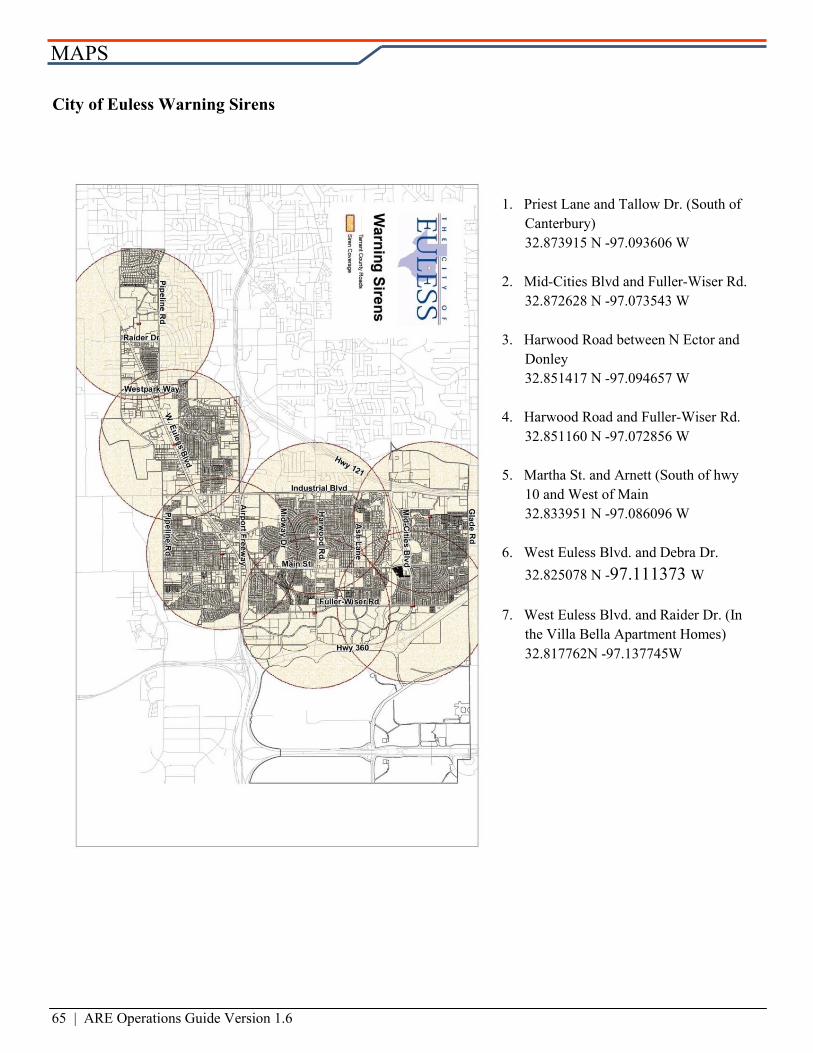
65 | ARE Operations Guide Version 1.6
City of Euless Warning Sirens
MAPS
1. Priest Lane and Tallow Dr. (South of
Canterbury)
32.873915 N -97.093606 W
2. Mid-Cities Blvd and Fuller-Wiser Rd.
32.872628 N -97.073543 W
3. Harwood Road between N Ector and
Donley
32.851417 N -97.094657 W
4. Harwood Road and Fuller-Wiser Rd.
32.851160 N -97.072856 W
5. Martha St. and Arnett (South of hwy
10 and West of Main
32.833951 N -97.086096 W
6. West Euless Blvd. and Debra Dr.
32.825078 N -97.111373 W
7. West Euless Blvd. and Raider Dr. (In
the Villa Bella Apartment Homes)
32.817762N -97.137745W

ARE Operations Guide Version 1.6 66
BAND PLAN
Note:
CW operation is permitted
throughout all amateur
bands.
= RTTY and Data
= phone and image
= CW only
= SSB phone
= USB phone, CW,
RTTY and data
= Fixed digital
message forwarding
systems only
E = Extra
A = Advanced
G = General
T = Technician
N = Novice
Band plan is from ARRL.org
Effective March 5, 2012

67 | ARE Operations Guide Version 1.6
Date Version Description Changed By
_______________________________________________________________________________
1/10/2014 1.0 Initial Publication James Knighton
1/28/2014 1.1 Update to Tarrant County EmComm James Knighton
Template Page 42
3/13/2014 1.2 Removed phone number on back page Chris Shanahan
4/9/2014 1.3 Added frequency on page 42 #15 Chris Shanahan
Changes maps on page 63 and 64
4/27/2014 1.4 Add ARRL Band Plan page 66 Chris Shanahan
10/8/2014 1.5 Add Activation Plan James Knighton
Update Comm Resource Worksheet
4/9/2015 1.6 New frequencies added to page 44 Chris Shanahan
8/11/2018 1.6 Change frequency # 2 on page 44 Chris Shanahan
REVISIONS

ARE Operations Guide Version 1.6 68
NOTES

Amateur Radio Euless
1102 W. Euless Blvd
Euless, TX 76040
www.w5eul.com
© 2014 Amateur Radio Euless


![MOBILE TRANSCEIVER [Amateur radio] - KENWOODmanual.kenwood.com/files/B5K-0414-00.pdf · MOBILE TRANSCEIVER [Amateur radio] SIMPLE GUIDE ÉMETTEUR-RÉCEPTEUR MOBILE [Radio amateur]](https://img.dokumen.tips/doc/110x75/5a78da067f8b9a77088bfc7e/mobile-transceiver-amateur-radio-transceiver-amateur-radio-simple-guide-metteur-rcepteur.jpg)


![Amateur Radio - NAØTC]](https://img.dokumen.tips/doc/110x75/626e144aa2e8ac70ca26c1f7/amateur-radio-natc.jpg)