Embed Size (px)
Citation preview

Crestron MC3 3-Series Control System® Operations Guide

Important Safety Instructions
• Read these instructions. • Keep these instructions. • Heed all warnings. • Follow all instructions. • Do not use this apparatus near water. • Clean only with dry cloth. • Do not block any ventilation openings. Install in accordance
with the manufacturer's instructions. • Do not install near any heat sources such as radiators, heat
registers, stoves, or other apparatus (including amplifiers) that produce heat.
• Do not defeat the safety purpose of the polarized or grounding-type plug. A polarized plug has two blades with one wider than the other. A grounding-type plug has two blades and a third grounding prong. The wide blade or the third prong are provided for your safety. If the provided plug does not fit into your outlet, consult an electrician for replacement of the obsolete outlet.
• Protect the power cord from being walked on or pinched particularly at plugs, convenience receptacles, and the point where they exit from the apparatus.
• Only use attachments/accessories specified by the manufacturer.
WARNING:
TO REDUCE THE RISK OF FIRE OR ELECTRIC SHOCK, DO NOT EXPOSE THIS APPARATUS TO RAIN OR MOISTURE. THE APPARATUS SHALL NOT BE EXPOSED TO DRIPPING OR SPLASHING. OBJECTS FILLED WITH LIQUIDS, SUCH AS VASES, SHOULD NOT BE PLACED ON THE APPARATUS.
WARNING:
TO PREVENT ELECTRIC SHOCK, DO NOT REMOVE COVER. THERE ARE NO USER SERVICEABLE PARTS INSIDE. ONLY QUALIFIED SERVICE PERSONNEL SHOULD PERFORM SERVICE.
The lightning flash with arrowhead symbol, within an equilateral triangle, is intended to alert the user to the presence of uninsulated “dangerous voltage” within the product's enclosure t hat may be of sufficient magnitude to constitute a risk of electric shock to persons.
• Use only with the cart, stand, tripod, bracket or table specified by the manufacturer or sold with the apparatus. When a cart is used, use caution when moving the cart/apparatus combination to avoid injury from tip-over.
The exclamation point within an equilateral triangle is intended to alert the user to the presence of important operating and maintenance (servicing) instructions in the literature accompanying the appliance.
WARNING:
THIS IS AN APPARATUS WITH CLASS I CONSTRUCTION. IT SHALL BE CONNECTED TO AN ELECTRICAL OUTLET WITH AN EARTHING GROUND TERMINAL.
IMPORTANT:
This device can be used with Class 2 output wiring.
• Unplug this apparatus during lightning storms or when unused for long periods of time.
• Refer all servicing to qualified service personnel. Servicing is required when the apparatus has been damaged in any way, such as power-supply cord or plug is damaged, liquid has been spilled or objects have fallen into the apparatus, the apparatus has been exposed to rain or moisture, does not operate normally, or has been dropped.
• Disconnect power prior to connecting or disconnecting equipment.
• Do not install in direct sunlight. • The apparatus must be installed in a way that the power cord
can be removed either from the wall outlet or from the device itself in order to disconnect the mains power.
• Prevent foreign objects from entering the device.

(Continued on following page)
Regulatory Compliance As of the date of manufacture, the MC3 has been tested and found to comply with specifications for CE marking and standards per EMC and Radiocommunications Compliance Labelling.
Federal Communications Commission (FCC) Compliance Statement CAUTION: Changes or modifications not expressly approved by the manufacturer responsible for compliance could void the user’s authority to operate the equipment.
NOTE: This equipment has been tested and found to comply with the limits for a Class B digital device, pursuant to part 15 of the FCC Rules. These limits are designed to provide reasonable protection against harmful interference in a residential installation. This equipment generates, uses and can radiate radio frequency energy and, if not installed and used in accordance with the instructions, may cause harmful interference to radio communications. However, there is no guarantee that interference will not occur in a particular installation. If this equipment does cause harmful interference to radio or television reception, which can be determined by turning the equipment off and on, the user is encouraged to try to correct the interference by one or more of the following measures:
• Reorient or relocate the receiving antenna
• Increase the separation between the equipment and receiver
• Connect the equipment into an outlet on a circuit different from that to which the receiver is connected
• Consult the dealer or an experienced radio/TV technician for help

A portion of the code in this product is covered by the Microsoft® Public License (Ms-PL), which can be found at www.microsoft.com/opensource/licenses.mspx. The specific patents that cover Crestron products are listed at patents.crestron.com. Crestron, the Crestron logo, 3-Series, 3-Series Control System, ADMS, Cameo, Core 3, Core 3 OS, Core 3 UI, Cresnet, Crestron Mobile, Crestron Mobile Pro, Crestron Studio, Crestron Toolbox, e-Control, Fusion RoomView, Fusion RV, infiNET EX, and Isys are either trademarks or registered trademarks of Crestron Electronics, Inc. in the United States and/or other countries. BACnet and the BACnet logo are either trademarks or registered trademarks of American Society of Heating, Refrigerating and Air-Conditioning Engineers, Inc. in the United States and/or other countries. Apple, iPad, iPhone, iPod, and Mac are either trademarks or registered trademarks of Apple, Inc. in the U.S. and/or other countries. EMerge Alliance and the EMerge Alliance logo are either trademarks or registered trademarks of Emerge Alliance Corporation in the United States and/or other countries. Android is either a trademark or a registered trademark of Google, Inc. in the United States and/or other countries. Internet Explorer, Microsoft and Windows are either trademarks or registered trademarks of Microsoft Corporation in the United States and/or other countries. Other trademarks, registered trademarks and trade names may be used in this document to refer to either the entities claiming the marks and names or their products. Crestron disclaims any proprietary interest in the marks and names of others. Crestron is not responsible for errors in typography or photography. This document was written by the Technical Publications department at Crestron. ©2013 Crestron Electronics, Inc.
Industry Canada (IC) Compliance Statement This device complies with Industry Canada license-exempt RSS standard(s). Operation is subject to the following two conditions: (1) this device may not cause interference and (2) this device must accept any interference, including interference that may cause undesired operation of the device.
Under Industry Canada regulations, this radio transmitter may only operate using an antenna of a type and maximum (or lesser) gain approved for the transmitter by Industry Canada. To reduce potential radio interference to other users, the antenna type and its gain should be so chosen that the equivalent isotropically radiated power (e.i.r.p.) is not more than that necessary for successful communication.
Industrie Canada (IC) Déclaration de conformité Le présent appareil est conforme aux CNR d'Industrie Canada applicables aux appareils radio exempts de licence. L'exploitation est autorisée aux deux conditions suivantes : (1) l'appareil ne doit pas produire de brouillage, et (2) l'utilisateur de l'appareil doit accepter tout brouillage radioélectrique subi, même si le brouillage est susceptible d'en compromettre le fonctionnement.
Conformément à la réglementation d'Industrie Canada, le présent émetteur radio peut fonctionner avec une antenne d'un type et d'un gain maximal (ou inférieur) approuvé pour l'émetteur par Industrie Canada. Dans le but de réduire les risques de brouillage radioélectrique à l'intention des autres utilisateurs, il faut choisir le type d'antenne et son gain de sorte que la puissance isotrope rayonnée équivalente (p.i.r.e.) ne dépasse pas l'intensité nécessaire à l'établissement d'une communication satisfaisante.
Le présent émetteur radio , IC: 5683C-CWD6660, a été approuvé par Industrie Canada pour fonctionner avec les types d'antenne énumérés ci-dessous et ayant un gain admissible maximal et l'impédance requise pour chaque type d'antenne. Les types d'antenne non inclus dans cette liste, ou dont le gain est supérieur au gain maximal indiqué, sont strictement interdits pour l'exploitation de l'émetteur.
Type d'antenne: Dipole, Gain admissible maximal: 2.5 dBi, Impédance: 50 Ohms
To satisfy RF exposure requirements, this device and its antenna must operate with a separation distance of at least 20 centimeters from all persons and must not be colocated or operating in conjunction with any other antenna or transmitter.

Crestron MC3 3-Series Control System
Operations Guide – DOC. 7095E Contents • i
Contents
3-Series Control System: MC3 1
Introduction ............................................................................................................................... 1 Features and Functions ................................................................................................ 1 Applications................................................................................................................. 5 Specifications .............................................................................................................. 6 Physical Description .................................................................................................... 9
Setup ........................................................................................................................................ 15 Network Wiring ......................................................................................................... 15 CAT5 Wiring ............................................................................................................. 15 Identity Code ............................................................................................................. 15 Installation ................................................................................................................. 16 Hardware Hookup ..................................................................................................... 16
Uploading and Upgrading ........................................................................................................ 18 Establishing Communication ..................................................................................... 18 Programs and Firmware ............................................................................................ 19
Operation ................................................................................................................................. 20 Configuring for Operations ....................................................................................... 20 Acquiring infiNET EX Devices ................................................................................ 32
Problem Solving ...................................................................................................................... 34 Troubleshooting ......................................................................................................... 34 Check Network Wiring .............................................................................................. 35 Reference Documents ................................................................................................ 36 Further Inquiries ........................................................................................................ 36 Future Updates .......................................................................................................... 36
Appendix A: The RF Spectrum ............................................................................................... 37 Appendix B: Optimum RF Reception Guidelines ................................................................... 38
Minimize Interference ............................................................................................... 38 Gateway Placement ................................................................................................... 38 Antenna Orientation .................................................................................................. 38
Return and Warranty Policies .................................................................................................. 40 Merchandise Returns / Repair Service ...................................................................... 40 Crestron Limited Warranty ........................................................................................ 40


Crestron MC3 3-Series Control System
Operations Guide – DOC. 7095E 3-Series Control System: MC3 • 1
3-Series Control System: MC3
Introduction The Crestron® MC3 presents a giant leap forward in control system design. Featuring the all new Core 3® control engine, the MC3 forms the core of the modern networked home, unleashing more power than ever for integrating home entertainment, AV distribution, security and environmental systems. With built-in infiNET EX® wireless technology, on-screen display, native mobile and Web based control, and onboard media rendering, the MC3 affords vast new, more affordable ways to control everything in the home through a streamlined hardware approach.
Features and Functions
(Continued on following page)
• Next generation control system for multimedia and whole-house control
• Core 3 OS™—Substantially faster and more powerful than other control systems
• Exclusive modular programming architecture • Vector floating point coprocessor and 128 KB L2 cache • Onboard 256 MB RAM & 2 GB Flash memory • Expandable storage up to 1 TB • Integrated infiNET EX wireless gateway • Industry-standard Ethernet and Cresnet® wired communications • Supports Crestron touch screens and other devices • Available RF and IR control options • Customizable OSD user interface • Component and composite video outputs • Onboard e-Control® Web Server • Supports Core 3 UI™ XPanel Web based remote control • Supports Crestron Mobile® control apps for iPhone®, iPad® and
Android™ • Supports Fusion RV® and SNMP remote management • Simplified Web access via myCrestron Dynamic DNS service • WAV, MP3, and WMA audio file playback • Built-in IR, COM, relay, and digital input ports • High-speed USB 2.0 host ports

3-Series Control System Crestron MC3
2 • 3-Series Control System: MC3 Operations Guide – DOC. 7095E
• Installer setup via on-screen display, Crestron Toolbox™ or Internet Explorer®1
• Backwards compatible to run existing SIMPL programs • Full Unicode (multi-language) support • Increased network throughput and security • Secure access through Active Directory integration or standalone
account management • IIS v.6.0 Web Server • IPv6 ready • External power supply included • Native BACnet®/IP support2 • Emerge Alliance® compatible
Features and Functions (Continued)
Core 3 OS Today's commercial buildings and custom homes comprise more technology than ever before, and all these systems need to be networked, managed, and controlled in fundamentally new ways. The IP based Core 3 platform is engineered from the ground up to deliver a network-grade server appliance capable of faithfully managing everything from boardroom AV and custom home theater to total building management.
More than a mere AV controller, the MC3 embodies a distinctively robust, dynamic, and secure platform to elevate system designs to higher levels of performance and reliability. Compared to other control systems, the MC3 provides a pronounced increase in processing power and speed with more memory, rock solid networking and IP control, and a unique modular programming architecture.
Modular Programming Architecture Designed for enhanced scalability, the MC3 affords high-speed, real-time multi-tasking to seamlessly run multiple programs simultaneously. This exclusive programming architecture lets programmers independently develop and run device specific programs for AV, lighting, HVAC, security, etc., allowing for the optimization of each program, and allowing changes to be made to one program without affecting the whole. Even as the system grows, processing resources can easily be shifted from one 3-Series™ processor to another without rewriting any code. The end benefit is dramatically simplified upgradability with minimal downtime, whether implementing changes on site or remotely via the network.
Robust Ethernet & IP Control IP technology is the heart of Core 3, so it should be no surprise that its networking abilities are second to none. High-speed Ethernet connectivity enables integration with IP-controllable devices and allows the MC3 to be part of a larger managed control network. Whether residing on a sensitive corporate LAN, a home network, or
1. Web-based installer setup requires the Microsoft® Internet Explorer Web browser running on a Windows® PC.
2. License required. The MC3 supports a maximum of 500 BACnet objects when dedicated for BACnet use only. Actual capabilities are contingent upon the overall program size and complexity.

Crestron MC3 3-Series Control System
Operations Guide – DOC. 7095E 3-Series Control System: MC3 • 3
accessing the Internet through a cable modem, the MC3 provides secure, reliable interconnectivity with touch screens, computers, mobile devices, media servers, video displays, security systems, and other equipment—whether on premises or across the globe.
e-Control Remote Access Years ago, Crestron pioneered the world’s first IP-based control system unleashing vast new possibilities for controlling, monitoring, and managing integrated systems over a LAN, WAN, and the Internet. Today, our many e-Control solutions offer more ways than ever for our users to control their worlds the way they want.
With e-Control, anything in a home or office can be controlled from anywhere in the world using a smartphone, tablet, or computer. Built-in Core 3 UI XPanel technology affords virtual touch screen control through any popular Web browser running on a laptop or desktop computer. Our Crestron Mobile Pro® app delivers the Crestron touch screen experience to an iPhone, iPad, or Android device, allowing safe monitoring and control of an entire facility using the one device that goes everywhere.
Remote access is simplified using the myCrestron Dynamic DNS service to establish a friendly URL for the home system. If technical support is ever needed, a Crestron system installer can even perform diagnostics and implement updates to the system remotely without coming on site.
Fusion RV and SNMP As part of a complete managed network in a corporate enterprise, college campus, convention center or any other facility, the MC3 works integrally with Crestron Fusion RV Remote Asset Management Software to enable remote scheduling, monitoring, and control of rooms and technology from a central help desk. Built-in SNMP support enables integration with third-party network management software, allowing control and monitoring in a format that is familiar to IT personnel.
infiNET EX Wireless Control Integrated infiNET EX technology provides an extremely easy and cost-effective way to add control of lighting, temperature, and other functions using Cameo® Wireless Dimmers and Keypads*, and infiNET EX Thermostats*. Adding an infiNET EX remote like Isys® MTX-3 Handheld Wireless Touch screen* or MLX-3 LCD Handheld Wireless Remote* enables sophisticated portable control over everything, whether simply watching TV or adjusting whole-house audio distribution, lighting, and climate control in every room. Perfect for existing structures and rentals, infiNET EX affords ultra-reliable 2-way wireless communications throughout the home without the need for physical control wiring.
Cresnet Cresnet provides a dependable network wiring solution for Crestron keypads, lighting controls, thermostats, and other devices that don’t require the higher speed of Ethernet. The Cresnet bus offers easy wiring and configuration, carrying bidirectional communication and 24 Vdc power to each device over a simple 4-conductor cable.
* Sold separately.

3-Series Control System Crestron MC3
4 • 3-Series Control System: MC3 Operations Guide – DOC. 7095E
On-Screen Display The MC3 includes the ability to control the home using just a television screen and a handheld remote1. Featuring customizable scrolling menus and full-color icons, the MC3 OSD makes it easy to select any room in the house, pick a music or video source, choose a radio station, TV channel, or media title, and even access lighting, climate, and security system controls. The MC3 OSD provides true-feedback so the status of the item being controlled is always available. Audio adjustments and lighting levels are clearly indicated using bar graphs. Room temperature and security system status can be viewed and controlled without leaving a favorite seat. Even metadata from an iPod®, ADMS®, or Internet radio tuner can be displayed to show the current playing song, movie, TV program, or radio station.
Audio File Playback Built-in audio signal rendering allows addition of audio feedback to the OSD, or generates door chimes, phone ringers, and other signals that can be played through the home theater or whole-house audio system. Load custom audio files to sound alarms, provide confirmation when a command is executed, deliver helpful voice prompts, or just play welcome music as the home theater system turns on.
Onboard Control Ports In addition to Ethernet, the MC3 includes two bidirectional RS-232 COM ports and five IR ports to interface directly with all centralized AV sources, video displays, and other devices. Two programmable relay ports are included for controlling window shades, a projection screen or lift, or other contact-closure controlled equipment. Two digital inputs are also provided for use with Crestron occupancy sensors, power sensors, door switches, or anything that provides a dry contact closure or low-voltage logic signal.
IR Wireless Option When equipped with the optional CNXRMIRD IR Receiver1, the MC3 affords a low-cost IR wireless control solution using any Crestron IR wireless remote or touch screen, such as the TPS-6X1, or a third-party universal IR remote.
BACnet/IP Native support for the BACnet/IP communication protocol provides a direct interface to third-party building management systems over Ethernet, simplifying integration with HVAC, security, fire and life safety, voice and data, lighting, shades, and other systems. Using BACnet/IP, each system runs independently with the ability to communicate together on one platform for a truly smart building.2
EMerge Alliance Registered The MC3 is EMerge Alliance registered and designed to work within a 24 Vdc room-level power distribution system. The EMerge Alliance is a non-for-profit open industry association leading the rapid adoption of safe dc power distribution in commercial buildings through the development of Emerge Alliance standards3. Crestron is a proud member and supporter of the Alliance. For more information about Crestron Solutions for EMerge Alliance Applications visit: www.crestron.com/emerge.
1. Sold separately. 2. License required. The MC3 supports a maximum of 500 BACnet objects when dedicated for BACnet
use only. Actual capabilities are contingent upon the overall program size and complexity. 3. Information regarding the EMerge Alliance can be found at www.emergealliance.org.
Crestron MC3 3-Series Control System
Operations Guide – DOC. 7095E 3-Series Control System: MC3 • 5
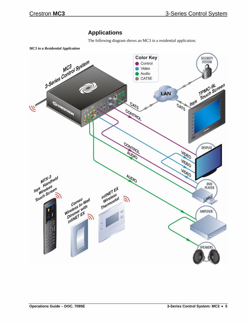
Applications The following diagram shows an MC3 in a residential application.
MC3 in a Residential Application

3-Series Control System Crestron MC3
6 • 3-Series Control System: MC3 Operations Guide – DOC. 7095E
Specifications Specifications for the MC3 are listed in the following table.
MC3 Specifications
SPECIFICATION DETAILS Control Engine Core 3 OS; real-time, preemptive
multi-threaded/multitasking kernel; Transaction-Safe Extended FAT file system; supports up to 10 simultaneously running program
Memory SDRAM 256 MB Flash 2 GB External Storage Up to 1 TB using USB mass storage device
(not included) Wired Communications
Ethernet 10/100 Mbps, auto-switching, auto-negotiating, auto-discovery, full/half duplex; industry-standard TCP/IP stack, UDP/IP, CIP, DHCP, SSL, IEEE 802.1X, SNMP, BACnet/IP, IPv4 or IPv6, Active Directory authentication, IIS v.6.0 Web Server, SMTP e-mail client, installer setup via Crestron Toolbox or Internet Explorer, supports all e-Control, Core 3 UI Xpanel, Crestron Mobile and Fusion RoomView® applications
Cresnet Cresnet master mode USB Supports USB HID and USB mass storage
class devices via rear panel USB 2.0 host ports, supports computer console via front panel USB 2.0 device port
RS-232 Supports 2-way device control and monitoring up to 115.2 kBd with hardware and software handshaking
IR/Serial Supports 1-way device control via infrared up to 1.2 MHz or serial TTL/RS-232 (0 - 5 volts) up to 115.2 kBd; Supports CNXRMIRD IR Receiver1
Wireless Communications
RF Transceiver infiNET EX 2-way RF, 2.4 GHz ISM, Channels 11-26 (2400 to 2483.5 MHz), default channel 15; IEEE 802.15.4 compliant
Range (typical) 150 ft (~46 m) indoor, 250 ft (~76 m) outdoor to nearest mesh network device(s), subject to site-specific conditions and individual device capabilities2
Device Support Maximum 100 infiNET EX devices (inclusive of up to 6 MTX-3 and/or MLX-3 remotes, supplied separately) and 5 infiNET EX expanders (model CLW-EXPEX, sold separately)
(Continued on following page)

Crestron MC3 3-Series Control System
Operations Guide – DOC. 7095E 3-Series Control System: MC3 • 7
MC3 Specifications (Continued)
SPECIFICATION DETAILS Graphics Engine (OSD) Built-in customizable control pages, scrolling
menus, and dynamic objects Video (OSD)
Output Signal Types Component (YPbPr), Composite Output Formats Progressive 480p or 576p, interlaced NTSC
or PAL Output Resolutions,
Component 720 x 480 @ 30 Hz (480i), 720 x 576 @ 25 Hz (576i), 720 x 480 @ 60 Hz (480p), 720 x 576 @ 50 Hz (576p)
Output Resolutions, Composite
480i, 576i
Audio Functions Audio file playback, audio signal pass-through
with mute during file playback Audio File Formats WAV (8 & 16-bit PCM, mono & stereo,
8 – 44.1 kHz sampling rates), MP3, WMA Input/Output Signal Types Analog stereo Analog-to-Digital/
Digital-to-Analog Conversion
24-bit 48 kHz
Performance (pass-through) Frequency Response S/N Ratio THD+N Stereo Separation
20 Hz to 20 kHz ±0.2 dB >93 dB, 20 Hz to 20 kHz A-weighted <0.01%, 20 Hz to 20 kHz >91 dB
Power Requirements Power Pack: 2.0 amps @ 24 volts dc;
100 – 240 volts ac, 50/60 Hz power pack included
Available Cresnet Power
35 watts (1.46 amps @ 24 volts dc) when using local power pack
Cresnet Power Usage 9 watts (0.375 amps @ 24 volts dc) when using Cresnet network power
Default Net ID 02 Environmental Temperature 41º to 113º F (5º to 45 ºC) Humidity 10% to 90% RH (non-condensing) Heat Dissipation 31 Btu/h Enclosure Chassis Aluminum with polycarbonate label overlay Faceplate Plastic with polycarbonate label overlay Mounting Freestanding (adhesive feet included)
(Continued on following page)

3-Series Control System Crestron MC3
8 • 3-Series Control System: MC3 Operations Guide – DOC. 7095E
MC3 Specifications (Continued)
SPECIFICATION DETAILS Dimensions Height 2.30 in (59 mm)
2.25 in (58 mm) without feet Width 8.12 in (207 mm) Depth 6.73 in (171 mm) including antenna Weight 2.5 lb (1.2 kg) Available Accessories
3-Series BACnet/IP Support 3-Series Native BACnet/IP Interface License
ANT-EXT Antenna Extenders C2N-HBLOCK Multi-type Cresnet Distribution Block CLW-EXPEX-GD-W-T infiNET EX Wireless Expander CNSP-XX Custom Serial Interface Cable CNXMIRD IR Receiver Crestron Mobile Pro Control App for iPhone, iPad and Android
Devices CSP-LIR-USB IR Learner Fusion RV Remote Asset Management Software RoomView Express Remote Help Desk and Resource
Management Software STIRP IR Emitter Probe with 3.5 mm
Mini Phone Plug 1. Sold separately. 2. The effective range of the entire wireless network is extended based on the placement and capabilities
of each network device. Consult the specifications for each wireless network device to verify wireless capabilities and limitations.

Crestron MC3 3-Series Control System
Operations Guide – DOC. 7095E 3-Series Control System: MC3 • 9
Physical Description This section provides information on the connections, controls and indicators available on the MC3.
MC3 Physical View (Front View)
MC3 Physical View (Rear View)

3-Series Control System Crestron MC3
10 • 3-Series Control System: MC3 Operations Guide – DOC. 7095E
MC3 Overall Dimensions (Top View)
8.00 in(204 mm)
5.10 in(130 mm)
0.38 in(10 mm)
8.12 in(207 mm)
1.39 in(35 mm)
5.34 in(136 mm)
MC3 Overall Dimensions (Side View)
2.30 in(59 mm)
2.14 in(55 mm)
2.25 in(58 mm)

Crestron MC3 3-Series Control System
Operations Guide – DOC. 7095E 3-Series Control System: MC3 • 11
MC3 (Front View)
2 3 4 5 6 71 8
MC3 (Rear View)
14 15 16 17
20 21
9 10 11
18
12
19
13
22
Connectors, Controls & Indicators
# CONNECTORS1, CONTROLS & INDICATORS
DESCRIPTION
1 COMPUTER Pin 2 Pin 1
Pin 3 Pin 4
(1) USB Type B female USB 2.0 computer console port 6 ft (2 m) cable included
PIN DESCRIPTION
1 +5 Vdc 2 Data - 3 Data + 4 Ground
2 PWR LED (1) Green LED, indicates operating power supplied from power pack or Cresnet network
3 NET LED (1) Amber LED, indicates communication with the Cresnet system
4 HW-R Button (1) Recessed push button for hardware reset 5 SW-R Button (1) Recessed push button for software reset
(Continued on following page)

3-Series Control System Crestron MC3
12 • 3-Series Control System: MC3 Operations Guide – DOC. 7095E
Connectors, Controls & Indicators (Continued)
# CONNECTORS1, CONTROLS & INDICATORS
DESCRIPTION
6 ACQUIRE (Button and LED)
(1) Recessed push button with red LED, used to set up connections with wireless devices
7 ACTIVITY (1) Red LED, indicates wireless communications
8 Antenna (1) Connection for supplied antenna 9 AUDIO IN (L – R)
(2) RCA female, unbalanced stereo line level audio input; Input level: 2 Vrms maximum; Input impedance: 7 kΩ nominal
10 AUDIO OUT (L – R)
(2) RCA female, unbalanced stereo line level audio output; Output level: 2 Vrms maximum; Output impedance: 100 Ω nominal
11 VIDEO OUT (Y, Pb, Pr)
(3) RCA female, component (YPbPr) video output; Output level: 1 Vp-p nominal (Y), 0.7 Vp-p nominal (PbPr); Output impedance: 75 Ω nominal
12 IR (1 – 5)
(5) 3.5 mm mini-phone jacks, IR/Serial output ports; IR output up to 1.2 MHz; 1-way serial TTL/RS-232 (0-5 volts) up to 115.2 kBd Use Crestron Infrared Emitter Probe (model STIRP, sold separately) for controlling infrared devices. For information on other serial control cables, contact Crestron.
TipRing
Sleeve Tip: IR Data Out Ring: No Connection Sleeve: Ground
13 COM (1 – 2)
(2) DB9 male, bidirectional RS-232 ports; Up to 115.2 kBd; hardware and software handshaking support. Use with a standard DB9 straight through cable. Pins 1, 4, 6 and 9 are not used but may be connected.
PIN DESCRIPTION
2 RXD - Receive Data 3 TXD - Transmit Data 5 SG - Signal Ground 7 RTS - Request To Send 8 CTS - Clear To Send
(Continued on following page)

Crestron MC3 3-Series Control System
Operations Guide – DOC. 7095E 3-Series Control System: MC3 • 13
Connectors, Controls & Indicators (Continued)
# CONNECTORS1, CONTROLS & INDICATORS
DESCRIPTION
14 LAN
GreenLED
YellowLED
Pin 8 Pin 1
(1) 8-wire RJ-45 jack; 10BASE-T/100BASE-TX Ethernet port; Green LED indicates link status; Yellow LED indicates Ethernet activity;
PIN SIGNAL PIN SIGNAL 1 TX + 5 N/C 2 TX - 6 RX - 3 RX + 7 N/C 4 N/C 8 N/C
15 RELAY (1 – 2)
(1) 4-pin 3.5 mm detachable terminal block comprising (2) normally open, isolated relays; Rated 1 amp, 30 volts ac/dc; MOV arc suppression across contacts
16 G
(1) 6-32 screw, chassis ground lug
17 INPUT (1 – 2)
(1) 3-pin 3.5 mm detachable terminal block comprising (2) programmable digital inputs (referenced to GND); Input voltage range: 0-24 volts dc; Logic threshold: ≥1.2 volts dc active/high, ≤0.46 volt dc inactive/low; Input impedance: 2.2 kΩ pulled up to 5 volts
18 VIDEO OUT (COMPOSITE)
(1) RCA female, composite video output; Output level: 1 Vp-p nominal; Output impedance: 75 Ω nominal
19 IR IN
(1) 3.5 mm TRS mini-phone jack; For connection of the CNXRMIRD IR receiver2; Allows IR wireless control from Crestron and third-party remotes using RC-5 IR commands.
TipRing
Sleeve Tip: IR Data In Ring: +5 Vdc Sleeve: Ground
(Continued on following page)

3-Series Control System Crestron MC3
14 • 3-Series Control System: MC3 Operations Guide – DOC. 7095E
Connectors, Controls & Indicators (Continued)
# CONNECTORS1, CONTROLS & INDICATORS
DESCRIPTION
20 USB (1 – 2)
Pins 1 2 3 4
(2) USB Type A female; USB 2.0 ports for storage and mouse/keyboard devices
PIN DESCRIPTION
1 +5 Vdc 2 Data - 3 Data + 4 Ground
21 NET3 (24 Y Z G)
(1) 4-pin 3.5 mm detachable terminal block, Cresnet master port; Outputs power to Cresnet devices if a power pack is connected to the 24VDC 2A power input jack; Receives Cresnet network power if no power pack is connected to the 24VDC 2A power input jack; Refer to “Power Requirements” in the “MC3 Specifications” table for additional specifications. 24: Power (24 volts dc) Y: Data Z: Data G: Ground
22 24VDC 2A3
+ -
(1) 2.1 x 5.5 mm dc power connector; 24 volt dc power input; Power supply included; Passes through to NET port to power Cresnet devices; Refer to “Power Requirements” in the “MC3 Specifications” table for additional specifications.
1. Interface connectors for RELAY, INPUT and NET ports are provided with the unit. 2. Sold separately. 3. The MC3 can be powered via the 24VDC 2A jack or the NET port. Be sure to use a Crestron
approved power supply as another may cause damage.

Crestron MC3 3-Series Control System
Operations Guide – DOC. 7095E 3-Series Control System: MC3 • 15
Setup
Network Wiring When wiring the Cresnet and Ethernet network, consider the following:
• Use Crestron Certified Wire.
• Use Crestron power supplies for Crestron equipment.
• Provide sufficient power to the system.
CAUTION: Insufficient power can lead to unpredictable results or damage to the equipment. Please use the Crestron Power Calculator to help calculate how much power is needed for the system (www.crestron.com/calculators).
For Cresnet networks with 20 or more devices, use a Cresnet Hub/Repeater (CNXHUB) to maintain signal quality.
For more details, refer to “Check Network Wiring” on page 35.
The MC3 can also use high-speed Ethernet for communications between the device and a control system, computer, digital media server and other IP-based devices.
For information on connecting Ethernet devices in a Crestron system, refer to the latest version of the Crestron e-Control Reference Guide (Doc. 6052), which is available from the Crestron Web site (www.crestron.com/manuals).
CAT5 Wiring Category 5 (CAT5) wiring is a twisted pair cable designed for Ethernet networks. These networks operate at speeds of up to 100 Megabits per second (Mbps) using the 100BASE-T standard. Crestron takes advantage of this specification for a variety of applications.
For more information, refer to the latest version of the Crestron CAT5 Wiring Reference Guide (Doc. 6137).
Identity Code NOTE: The latest software can be downloaded from the Crestron Web site (www.crestron.com/software).
Net ID The Net ID of the MC3 has been factory set to 02. This Net ID is always defined as the “master” control system on the Cresnet network.
IP ID The IP ID is set within the MC3’s IP table using Crestron Toolbox. For information on setting an IP table, refer to the Crestron Toolbox help file.
NOTE: The IP ID for multiple MC3s should be the same if the MC3s need to communicate with each other.
When setting the IP ID, consider the following:
• The IP ID of each unit must match an IP ID specified in the Crestron Studio™ or SIMPL Windows program.

3-Series Control System Crestron MC3
16 • 3-Series Control System: MC3 Operations Guide – DOC. 7095E
• Each device using IP to communicate with a control system must have a unique IP ID.
Installation Ventilation The MC3 should be used in a well-ventilated area. To prevent overheating, do not
operate this product in an area that exceeds the environmental temperature range listed in the table of specifications. Consider using forced air ventilation and/or incrementing the spacing between units to reduce overheating. Consideration must be given if installed in a closed or multi-unit rack assembly since the operating ambient temperature of the environment may be greater than the room ambient temperature. Contact with thermal insulating materials should be avoided on all sides of the unit.
Stacking Four “feet” are attached to the MC3 so that the rubber feet can provide stability when the unit is placed on a flat surface or stacked.
NOTE: No more than two MC3 units should be stacked.
Hardware Hookup Make the necessary connections as called out in the illustrations that follow this paragraph. Refer to “Network Wiring” on page 15 before attaching the 4-position terminal block connector. Apply power after all connections have been made.
When making connections to the MC3, note the following:
• Use Crestron power supplies for Crestron equipment.
• The included cables cannot be extended.
Hardware Connections for the MC3 (Front View)
COMPUTER :To Computer Console

Crestron MC3 3-Series Control System
Operations Guide – DOC. 7095E 3-Series Control System: MC3 • 17
Hardware Connections for the MC3 (Rear View – Audio, Video and IR Connections)
AUDIO IN (L R):From Audio Source
AUDIO OUT (L R):To OSD Device or
Associated Amplifier
VIDEO OUT (Y, Pb, Pr):To OSD Device
VIDEO OUT (COMPOSITE):To OSD Device
IR (1– 5):To IR Controlled
Devices
IR IN :From IR Device
NOTE: Video is routed to the output selected in the program loaded on the MC3.
Hardware Connections for the MC3 (Rear View – COM, LAN, Relay, Ground, Input, Power, NET and USB Connections)
USB (1– 2):To USB HID Device or
USB Mass Storage Device
LAN:10/100 BASE-TEthernet to LAN
COM (1– 2):To RS-232 Device
RELAY (1– 2):To Controllable Devices
INPUT:From Control
Devices
24V = 2.0A:From Power Supply
NET:To Network Device
Ground
NOTE: Ensure the unit is properly grounded by connecting the chassis ground lug to an earth ground (building steel).
NOTE: To prevent overheating, do not operate this product in an area that exceeds the environmental temperature range listed in the table of specifications.

3-Series Control System Crestron MC3
18 • 3-Series Control System: MC3 Operations Guide – DOC. 7095E
Uploading and Upgrading Crestron recommends using the latest programming software and that each device contains the latest firmware to take advantage of the most recently released features. However, before attempting to upload or upgrade it is necessary to establish communication. Once communication has been established, files (such as programs or firmware) can be transferred to the control system (or device). Finally, program checks can be performed (such as changing the device ID or creating an IP table) to ensure proper functioning.
While the next section provides an overview for communication, refer to “Establishing Communications with the Control System” in the latest version of the Crestron 3-Series Control Systems Reference Guide (Doc. 7150) for connection details. If communications cannot be established, refer to “Troubleshooting Communications” in the same guide.
NOTE: Crestron software and any files on the Web site are for authorized Crestron dealers and Crestron Service Providers (CSPs) only. New users must register to obtain access to certain areas of the site (including the FTP site).
Establishing Communication Use Crestron Toolbox for communicating with the MC3; refer to the Crestron Toolbox help file for details. There are two methods of communication: USB and TCP/IP.
USB USB Communication
MC3
PC Running�Crestron Toolbox
C O M PU TER
PWRN ETH W-RSW-RA C Q U IR E
A C TIVITYUSB
The COMPUTER port on the MC3 connects to the USB port on the PC via the included Type A to Type B USB cable:
1. Click Tools | System Info.
2. Click the icon.
3. For Connection Type, select USB. When multiple USB devices are connected, identify the MC3 by entering “MC3” in the Model text box, the unit’s serial number in the Serial text box or the unit’s hostname (if known) in the Hostname text box.
4. Click OK. Communications are confirmed when the device information is displayed.
Crestron MC3 3-Series Control System
Operations Guide – DOC. 7095E 3-Series Control System: MC3 • 19
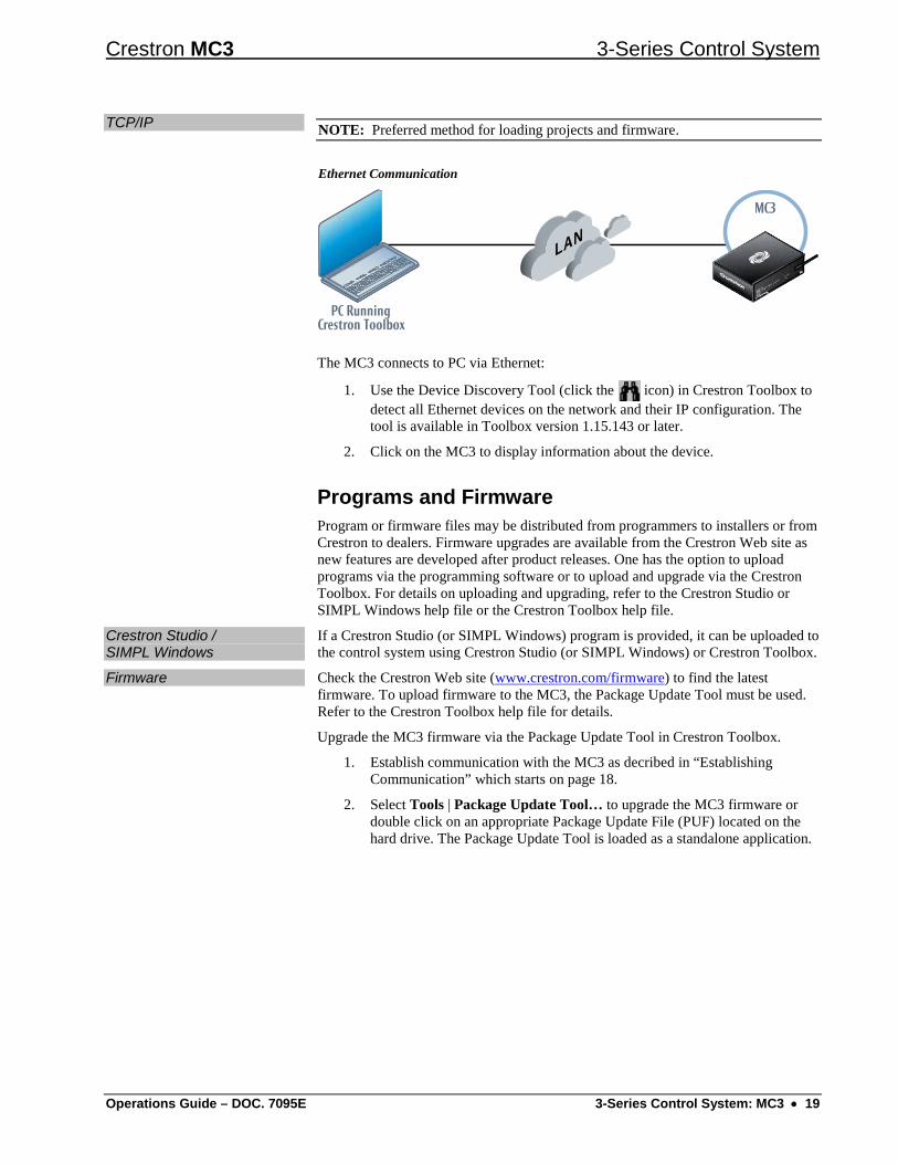
TCP/IP NOTE: Preferred method for loading projects and firmware.
Ethernet Communication
MC3
PC Running�Crestron Toolbox
LAN
C O M PU TER
PWRN ETH W-RSW-RA C Q U IR E
A C TIVITY
The MC3 connects to PC via Ethernet:
1. Use the Device Discovery Tool (click the icon) in Crestron Toolbox to detect all Ethernet devices on the network and their IP configuration. The tool is available in Toolbox version 1.15.143 or later.
2. Click on the MC3 to display information about the device.
Programs and Firmware Program or firmware files may be distributed from programmers to installers or from Crestron to dealers. Firmware upgrades are available from the Crestron Web site as new features are developed after product releases. One has the option to upload programs via the programming software or to upload and upgrade via the Crestron Toolbox. For details on uploading and upgrading, refer to the Crestron Studio or SIMPL Windows help file or the Crestron Toolbox help file.
Crestron Studio / SIMPL Windows
If a Crestron Studio (or SIMPL Windows) program is provided, it can be uploaded to the control system using Crestron Studio (or SIMPL Windows) or Crestron Toolbox.
Firmware Check the Crestron Web site (www.crestron.com/firmware) to find the latest firmware. To upload firmware to the MC3, the Package Update Tool must be used. Refer to the Crestron Toolbox help file for details.
Upgrade the MC3 firmware via the Package Update Tool in Crestron Toolbox.
1. Establish communication with the MC3 as decribed in “Establishing Communication” which starts on page 18.
2. Select Tools | Package Update Tool… to upgrade the MC3 firmware or double click on an appropriate Package Update File (PUF) located on the hard drive. The Package Update Tool is loaded as a standalone application.

3-Series Control System Crestron MC3
20 • 3-Series Control System: MC3 Operations Guide – DOC. 7095E
Operation
Configuring for Operations Before setting up the MC3 the time and time zone must be configured. Use the Crestron Toolbox to connect to the MC3; refer to “Establishing Communication” which starts on page 18 for additional details. Select Functions | System Clock… and make the appropriate changes.
Configuration can be completed through the use of the Web based setup. The following screen appears on the Web page after communication is established. Navigate the screens and make the appropriate selections. To access the configuration pages, enter the IP address of the controller in the Web browser followed by ‘/setup’ (for example, ‘http://172.30.168.19/setup’). The control system’s initial screen is displayed.
Initial Screen
Click the Setup button to display the “MC3 Setup” menu.

Crestron MC3 3-Series Control System
Operations Guide – DOC. 7095E 3-Series Control System: MC3 • 21
The “MC3 Setup” menu displays the IP address, hostname and MAC address of the device. It also allows access to various setup and programming screens. The “MC3 Setup” menu contains buttons for Ethernet Setup, Audio Setup, Video Setup, Application Setup, Input/Output Control, Diagnostics, and About, as shown in the illustration below. Each button is described in subsequent paragraphs.
“MC3 Setup” Menu
Click the icon to return to the previous screen.

3-Series Control System Crestron MC3
22 • 3-Series Control System: MC3 Operations Guide – DOC. 7095E
Ethernet Setup From the “MC3 Setup” menu, click Ethernet Setup to enter the “Ethernet Setup” menu. The “Ethernet Setup” menu displays DHCP, Hostname, IP Address, Subnet Mask, Default Router, Domain, and MAC Address settings.
“Ethernet Setup” Menu
The “Ethernet Setup” menu also allows the following actions:
• Select Off or On for the DHCP server (default is off), as shown in the illustration above.
• Click Edit to the right of Hostname to change the hostname.
• Click Edit to the right of IP Address to change the IP address.
• Click Edit to the right of Subnet Mask to change the subnet mask.
• Click Edit to the right of Default Router to change the default router.
• Click Edit to the right of Domain to change the domain name.
• Click Advanced Settings to specify DNS servers, Webserver settings, and SSL settings.
• Click MyCrestron Dynamic DNS to configure the myCrestron.com Dynamic DNS service.
• Click Ethernet Diagnostics to test Ethernet communications.
• Click Reboot to reboot the MC3.

Crestron MC3 3-Series Control System
Operations Guide – DOC. 7095E 3-Series Control System: MC3 • 23
Advanced Settings From the “Ethernet Setup” menu, click Advanced Settings to add, remove, or change the settings for the DNS servers and SSL security settings. Refer to the following illustration.
“Advanced Ethernet Setup” Screen
Change the Webserver state by clicking the On or Off button. The default setting is on. Turning the Webserver off disables access to setup from a Web browser.
NOTE: Setting the Webserver to the “Off” state results in disabling access to this setup program from a Web browser. To re-enable it, use Crestron Toolbox to connect to the control system and turn the Webserver back on.
To set the SSL settings click the Off, Self, or CA button.
• Off turns off the SSL capabilities of the MC3.
• Self sets up self signing certificates.
• CA uses an authority to assign the SSL settings.
Refer to the latest version of the 3-Series Control Systems Reference Guide (Doc. 7150) for more details on SSL settings. Using the Edit buttons change the port numbers to match the network settings.
NOTE: Changing the CIP Port to something other than 41794 results in disabling access to this setup program from a Web browser. In order to re-enable it, use Crestron Toolbox to connect to the control system, and set the CIP Port back to 41794.
Click Reboot to reboot the MC3 or the icon to return to the previous menu.

3-Series Control System Crestron MC3
24 • 3-Series Control System: MC3 Operations Guide – DOC. 7095E
MyCrestron Dynamic DNS Using a PC with Internet Explorer navigate to http://www.mycrestron.com and register the system with Crestron.
From the “Ethernet Setup” menu, click MyCrestron Dynamic DNS to configure the settings for the dynamic DNS server. Use the information provided from the MyCrestron home page to complete the information on the “MyCrestron Dynamic DNS Setup” screen. Press Edit to the right of Domain and enter the domain name that was chosen. Click Edit to the right of Password and enter the password that was chosen.
“MyCrestron Dynamic DNS Setup” Screen
Once completed the text on the screen updates and confirms that the DNS setup was successful.
Click the icon to return to the previous menu.
Ethernet Diagnostics From the “Ethernet Setup” menu, click Ethernet Diagnostics to perform various troubleshooting steps; refer to the illustrations on the following page.
Tests can be run on the MC3 to verify connections. Click Ping Default Router to ping the router. To verify external communications, the Crestron Web site may be pinged by clicking Ping Crestron.com.

Crestron MC3 3-Series Control System
Operations Guide – DOC. 7095E 3-Series Control System: MC3 • 25
“Ethernet Diagnostics” Screen
Communications is verified when the message Passed is displayed. Refer to the image below for details.
Click Who to display a list of devices that are connected to the PC via the Ethernet connection. These devices may be Crestron Ethernet devices, third-party Ethernet devices and PCs (including any PC using Crestron Toolbox to connect to the processor over Ethernet).
“Ethernet Diagnostics” Screen with List of Connected Devices
Click Details to view a detailed text window that displays the status of the ping operation, including the time that it took to get a response.
Click the icon to return to the previous menu.

3-Series Control System Crestron MC3
26 • 3-Series Control System: MC3 Operations Guide – DOC. 7095E
Audio Setup From the “MC3 Setup” menu, click Audio Setup to open the “Audio” screen. The audio settings can be configured to the appropriate levels for the connected device.
Click Play Test to play the test audio and verify the volume is set at an appropriate level. Adjust the volume using the up and down arrows. Click the Play Test button again to stop playing the test file. Refer to the following illustration.
“Audio” Screen
The Mute On button mutes all audio coming from the MC3 to the audio device. The Mute Off button allows the audio to go to the audio device.
Click the icon to return to the previous menu.

Crestron MC3 3-Series Control System
Operations Guide – DOC. 7095E 3-Series Control System: MC3 • 27
Video Setup From the “MC3 Setup” menu click on Video Setup to enter the “Video” screen. The “Video” screen enables the MC3 to send video that matches the resolution of the display. Refer to the following illustration.
“Video” Screen
The video resolution must be properly set in order for the display device to show it correctly. Select an appropriate resolution for the connected display.
Click the icon to return to the previous menu.
Application Setup From the “MC3 Setup” menu, click Application Setup to open the “Application Setup” menu. The “Application Setup” menu allows the up to ten programs that are loaded onto the MC3 to be viewed. This menu enables or disables programs’ ability to run when the device boots; programs can also be started or stopped. The menu also displays essential IP table information and details about the program.
Click Register to enable the program to load on the device. A registered program starts when the MC3 boots. Click Unregister to prevent the program from loading when the MC3 boots.
To start or stop a program click the Start or Stop button next to the desired program. Refer to the illustration on the next page.

3-Series Control System Crestron MC3
28 • 3-Series Control System: MC3 Operations Guide – DOC. 7095E
“Application Setup” Menu
Click the icon to return to the previous menu.
Application Setup – IP Table From the “Application Setup” menu, click IP Table to view the IP table associated with the specific program. Refer to the following illustration.
The “Application Setup” (IP Table) screen allows viewing of the IP table. Use the up or down arrow to scroll through the screen.
“Application Setup” (IP Table) Screen
Click the icon to return to the previous menu.

Crestron MC3 3-Series Control System
Operations Guide – DOC. 7095E 3-Series Control System: MC3 • 29
Application Setup - Details From the “Application Setup” menu, click Details to view specific source and program information of a program. The “Application Setup” (Details) screen permits a detailed view of the program. Use the up or down arrow to scroll through the screen. Refer to the following illustration.
“Application Setup” (Details) Screen
Click the icon to return to the previous menu.
Input/Output Control From the “MC3 Setup” menu, click Input/Output Control to open the “I/O Control” screen. The MC3 allows control over a wide array of devices that may require specific communication settings. Use this screen to configure the control settings.
Select Com 1 or Com 2 and make the appropriate selections for the device connected to the MC3. The screen displays communication messages that are made between the device and the MC3. Use the record button to store the last 20 lines of data.
NOTE: Twenty lines of data are stored on the MC3, but only five are displayed on the screen.
Click the pause button to interrupt the recording but allow the data log to remain intact. The Clear button clears the data stored in the screen. Refer to the illustration on the following page.
The status of the digital inputs is indicated by the green on-screen LEDs.

3-Series Control System Crestron MC3
30 • 3-Series Control System: MC3 Operations Guide – DOC. 7095E
“I/O Control” Screen
The Open and Close buttons for the relays allow testing of the connected devices. Click the Open and Close buttons to test the device. The on-screen LED illuminates green to show that the relay is closed.
Click the icon to return to the previous menu.
Diagnostics From the “MC3 Setup” menu click Diagnostics to enter the “Diagnostics” menu. The “Diagnostics” menu contains buttons that provide information about the connected devices, hardware configuration and error logs.
Click Show Cresnet Devices or Show InfiNET EX Devices to display the Cresnet or infiNET devices that are connected to the network. Refer to the following illustration.
“Diagnostics” Menu

Crestron MC3 3-Series Control System
Operations Guide – DOC. 7095E 3-Series Control System: MC3 • 31
Click Show Hardware Configuration to display a list of cards in the MC3. Refer to the following illustration for more details.
“Hardware Configuration” Screen
To navigate through the device list use the Last button to jump to the end of the list, the First button to jump to the beginning of the list, or the up / down arrows to scroll through the list.
The MC3 stores and displays vital system information that can be referred to when troubleshooting the device or performing diagnostics on the system. From the “Diagnostics” menu, click Show Message Log to display events that have been stored by the MC3. Show Last Reboot Message displays the final message stored before the device was reset.
Click the icon to return to the previous menu.

3-Series Control System Crestron MC3
32 • 3-Series Control System: MC3 Operations Guide – DOC. 7095E
About From the “MC3 Setup” menu, click About to open the “About” screen. This screen displays firmware versions for the Operating System, RF Gateway, and IR Gateway. Click Show Details to display low level firmware information about each device. Refer to the following illustration.
“About” Screen
Click the icon to return to the previous menu.
Acquiring infiNET EX Devices The MC3 can communicate with up to 100 infiNET EX devices on the same channel. Each device must have an RF channel assignment that matches the RF channel assignment of the gateway.
Crestron infiNET EX devices can communicate with an MC3 only if they have been acquired by that MC3. The Acquire mode can be activated from Crestron Toolbox (recommended) or with the ACQUIRE button on the MC3.
The operating channel of the MC3 must be set prior to operation using Crestron Toolbox. The MC3 can operate on one of 16 channels. The MC3 can operate on a fixed channel that is set by the installer. The default RF channel is 15.
There are 16 possible channels ranging from 11 to 26. For optimum performance when installing a MC3 in a Wi-Fi environment, do not set the MC3 to a channel within a Wi-Fi channel band. Crestron recommends channel 15 or channel 20.

Crestron MC3 3-Series Control System
Operations Guide – DOC. 7095E 3-Series Control System: MC3 • 33
• Channels 11 – 14 are within Wi-Fi channel 1.
• Channel 15 is adjacent to Wi-Fi channels 1 and 6.
• Channels 16 – 19 are within Wi-Fi channel 6.
• Channel 20 is adjacent to Wi-Fi channels 6 and 11.
• Channels 21 – 24 are within Wi-Fi channel 11.
• Channel 25 is adjacent to Wi-Fi channel 11.
• Channels 26 is neither within nor adjacent to any Wi-Fi band.
For detailed information on RF channels, refer to “Appendix A: The RF Spectrum” on page 37 and “Appendix B: Optimum RF Reception Guidelines” which starts on page 38.
Establish communication with the MC3 (refer to “Establishing Communication” which starts on page 18); use Crestron Toolbox to set the operating channel. Set the RF channel by selecting Functions | MC3… in Crestron Toolbox. Refer to the Crestron Toolbox Help file for more details.
NOTE: Use Crestron Toolbox to set the RF channel before starting the acquire process. The default RF channel is 15. If the RF channel on a device is changed, it must be acquired again.
NOTE: The Acquire mode can be activated approximately 15 seconds after applying power to the MC3.
NOTE: In an environment with multiple gateways, only one gateway should be in Acquire mode at a time.
NOTE: The MC3 must be placed in Acquire mode before an infiNET EX device is placed in Acquire mode.
To acquire an infiNET EX device via the ACQUIRE button on the MC3:
1. Press ACQUIRE on the MC3 to enter Acquire mode. The accompanying LED illuminates, indicating the unit is ready to link to infiNET EX devices.
NOTE: Acquire mode automatically deactivates after one hour. This default timeout period can be changed from Crestron Toolbox.
2. Bring the infiNET EX device within range of the MC3 and place it in Acquire mode as described in its manual. The device is automatically acquired by the gateway within two minutes after it enters Acquire mode.
3. Repeat step 2 for each infiNET EX device to be acquired.
4. To exit the Acquire mode, press ACQUIRE on the MC3. The LED turns off.
3-Series Control System Crestron MC3
34 • 3-Series Control System: MC3 Operations Guide – DOC. 7095E
Problem Solving
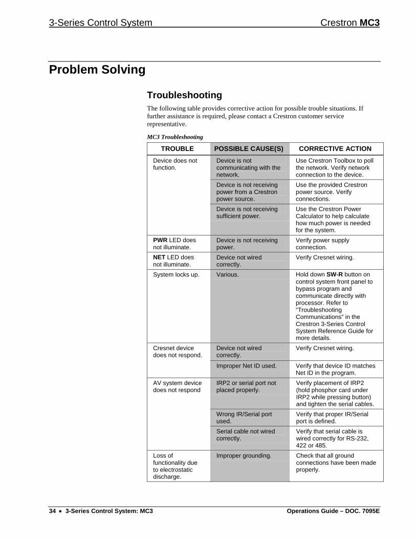
Troubleshooting The following table provides corrective action for possible trouble situations. If further assistance is required, please contact a Crestron customer service representative.
MC3 Troubleshooting
TROUBLE POSSIBLE CAUSE(S) CORRECTIVE ACTION Device does not function.
Device is not communicating with the network.
Use Crestron Toolbox to poll the network. Verify network connection to the device.
Device is not receiving power from a Crestron power source.
Use the provided Crestron power source. Verify connections.
Device is not receiving sufficient power.
Use the Crestron Power Calculator to help calculate how much power is needed for the system.
PWR LED does not illuminate.
Device is not receiving power.
Verify power supply connection.
NET LED does not illuminate.
Device not wired correctly.
Verify Cresnet wiring.
System locks up. Various. Hold down SW-R button on control system front panel to bypass program and communicate directly with processor. Refer to “Troubleshooting Communications” in the Crestron 3-Series Control System Reference Guide for more details.
Cresnet device does not respond.
Device not wired correctly.
Verify Cresnet wiring.
Improper Net ID used. Verify that device ID matches Net ID in the program.
AV system device does not respond
IRP2 or serial port not placed properly.
Verify placement of IRP2 (hold phosphor card under IRP2 while pressing button) and tighten the serial cables.
Wrong IR/Serial port used.
Verify that proper IR/Serial port is defined.
Serial cable not wired correctly.
Verify that serial cable is wired correctly for RS-232, 422 or 485.
Loss of functionality due to electrostatic discharge.
Improper grounding. Check that all ground connections have been made properly.

Crestron MC3 3-Series Control System
Operations Guide – DOC. 7095E 3-Series Control System: MC3 • 35
Check Network Wiring Use the Right Wire In order to ensure optimum performance over the full range of the installation
topology, Crestron Certified Wire and only Crestron Certified Wire may be used. Failure to do so may incur additional charges if support is required to identify performance deficiencies because of using improper wire.
Calculate Power CAUTION: Use only Crestron power supplies for Crestron equipment. Failure to do so could cause equipment damage or void the Crestron warranty.
CAUTION: Provide sufficient power to the system. Insufficient power can lead to unpredictable results or damage to the equipment. Please use the Crestron Power Calculator to help calculate how much power is needed for the system (www.crestron.com/calculators).
When calculating the length of wire for a particular Cresnet run, the wire gauge and the Cresnet power usage of each network unit to be connected must be taken into consideration. Use Crestron Certified Wire only. If Cresnet units are to be daisy chained on the run, the Cresnet power usage of each network unit to be daisy chained must be added together to determine the Cresnet power usage of the entire chain. If the unit is home-run from a Crestron system power supply network port, the Cresnet power usage of that unit is the Cresnet power usage of the entire run. The wire gauge and the Cresnet power usage of the run should be used in the following equation to calculate the cable length value on the equation’s left side.
Cable Length Equation
L = Length of run (or chain) in feetR = 6 Ohms (Crestron Certified Wire: 18 AWG (0.75 mm ))
or 1.6 Ohms (Cresnet HP: 12 AWG (4 mm ))P = Cresnet power usage of entire run (or chain)
2
2L < 40,000R x P
Where:
Make sure the cable length value is less than the value calculated on the right side of the equation. For example, a Cresnet run using 18 AWG Crestron Certified Wire and drawing 20 watts should not have a length of run more than 333 feet (101 meters). If Cresnet HP is used for the same run, its length could extend to 1250 feet (381 meters).
NOTE: All Crestron certified Cresnet wiring must consist of two twisted pairs. One twisted pair is the 24 and G pair and the other twisted pair is the Y and Z pair.
Strip and Tin Wire When daisy chaining Cresnet units, strip the ends of the wires carefully to avoid nicking the conductors. Twist together the ends of the wires that share a pin on the network connector and tin the twisted connection. Apply solder only to the ends of the twisted wires. Avoid tinning too far up the wires or the end becomes brittle. Insert the tinned connection into the Cresnet connector and tighten the retaining screw. Repeat the procedure for the other three conductors.
Add Hubs Use of a Cresnet Hub/Repeater (CNXHUB) is advised whenever the number of Cresnet devices on a network exceeds 20 or when the combined total length of Cresnet cable exceeds 3000 feet (914 meters).

3-Series Control System Crestron MC3
36 • 3-Series Control System: MC3 Operations Guide – DOC. 7095E
Reference Documents The latest version of all documents mentioned within the guide can be obtained from the Crestron Web site (www.crestron.com/manuals).
List of Related Reference Documents
DOCUMENT TITLE 3-Series Control Systems Reference Guide CAT5 Wiring Reference Guide Crestron e-Control Reference Guide
Further Inquiries To locate specific information or to resolve questions after reviewing this guide, contact Crestron's True Blue Support at 1-888-CRESTRON [1-888-273-7876] or refer to the listing of Crestron worldwide offices on the Crestron Web site (www.crestron.com/offices) for assistance within a particular geographic region.
To post a question about Crestron products, log onto the Online Help section of the Crestron Web site (www.crestron.com/onlinehelp). First-time users must establish a user account to fully benefit from all available features.
Future Updates As Crestron improves functions, adds new features and extends the capabilities of the MC3, additional information may be made available as manual updates. These updates are solely electronic and serve as intermediary supplements prior to the release of a complete technical documentation revision.
Check the Crestron Web site periodically for manual update availability and its relevance. Updates are identified as an “Addendum” in the Download column.

Crestron MC3 3-Series Control System
Operations Guide – DOC. 7095E 3-Series Control System: MC3 • 37
Appendix A: The RF Spectrum Crestron’s RF network provides 16 RF channels in the 2.4GHz ISM* band, specifically IEEE 802.15.4 channels 11 through 26. The 16 channels define the frequencies at which the RF device communicates.
RF devices on different channels do not communicate or interfere with each other. However, since some of the channels are in the 2.4GHz ISM band (as shown in the following diagram), interference can occur with other devices using this band, such as 802.11b/g Wi-Fi devices, Crestron infiNET devices or Zigbee devices, although the differing protocols do not allow a link to be established or data to be transferred. Wireless 2.4GHz telephones and microwave ovens may also cause interference with the network.
IEEE 802.15.4 channel selection (2400 MHz PHY)
Channel 11(802.11b/g)
Channel 6(802.11b/g)
Channel 1(802.11b/g)
Channel11 12 13 14 15 16 17 18 19 20 21 22 23 24 25 26
22 MHz2 MHz
2483.5 MHz
2480
2462 MHz
2465 2470 247524602445 2450 24552440
2437 MHz
2435243024252420241524102405
2412 MHz2400 MHz
Wi-Fi (802.11b/g)RF (802.15.4)
* Industrial, Scientific and Medical; refers to frequency range used for unlicensed communication applications, such as Wi-Fi.

3-Series Control System Crestron MC3
38 • 3-Series Control System: MC3 Operations Guide – DOC. 7095E
Appendix B: Optimum RF Reception Guidelines Many factors can affect the reliability of RF communication between an RF gateway and an RF device. While an effort has been made to determine operating specifications, some specifications are not constant. RF Communication can be limited by several factors including but not limited to EMI (electromagnetic interference), intervening objects, antenna orientation and receiver placement. To obtain maximum reliability and performance, some basic rules for installing RF transceivers are listed below.
Minimize Interference RF reception range can be hindered by spurious EMI noise that may interfere with or mask the desired frequency, thereby reducing useable range. EMI is generated by any electrical device at various RF noise levels depending on the device. Sources of EMI include computers, video equipment, digital processors, lighting dimmers, lighting ballasts, motors or any large ac source. Every effort should be made to separate any RF transceiver from these sources of RF noise including Audio Visual equipment in racks. If a gateway must be installed in an equipment rack, make sure there is ample separation between the equipment and the gateway.
Gateway Placement Optimum reception for any RF transceiver is obtained by installing the gateway transceiver in an open area or shelf with a clear line of sight (no obstructions between gateway and receiver). Crestron recommends that the gateway is at least five to six feet high for best results. Avoid placing transceivers or transmitters at a low height or on the ground. Placing RF equipment near metal objects, walls, corners or metal enclosures compromises RF propagation and reception. Try to avoid installing gateways in equipment racks, service rooms, electrical closets or rooms other than that in which the panel is located.
Antenna Orientation The antenna orientation on Crestron gateways has considerable effect on range and reliability. The best orientation is unique to each installation. There are three possible antenna orientations:
• Point the antenna horizontally (parallel to the ground).
• Point the antenna vertically.
• Point the antenna at a right angle to the gateway.
Never point the antenna downward as this decreases range and reliability. Refer to illustrations on the following pages for examples of the different antenna orientations.
NOTE: RF propagation is best from the sides of the antenna.

Crestron MC3 3-Series Control System
Operations Guide – DOC. 7095E 3-Series Control System: MC3 • 39
Horizontal Orientation
Building
Antenna
Vertical Orientation
Antenna
Right Angle Orientation
Antenna

3-Series Control System Crestron MC3
40 • 3-Series Control System: MC3 Operations Guide – DOC. 7095E
Return and Warranty Policies
Merchandise Returns / Repair Service 1. No merchandise may be returned for credit, exchange or service without prior authorization from
Crestron. To obtain warranty service for Crestron products, contact an authorized Crestron dealer. Only authorized Crestron dealers may contact the factory and request an RMA (Return Merchandise Authorization) number. Enclose a note specifying the nature of the problem, name and phone number of contact person, RMA number and return address.
2. Products may be returned for credit, exchange or service with a Crestron Return Merchandise Authorization (RMA) number. Authorized returns must be shipped freight prepaid to Crestron, 6 Volvo Drive, Rockleigh, N.J. or its authorized subsidiaries, with RMA number clearly marked on the outside of all cartons. Shipments arriving freight collect or without an RMA number shall be subject to refusal. Crestron reserves the right in its sole and absolute discretion to charge a 15% restocking fee plus shipping costs on any products returned with an RMA.
3. Return freight charges following repair of items under warranty shall be paid by Crestron, shipping by standard ground carrier. In the event repairs are found to be non-warranty, return freight costs shall be paid by the purchaser.
Crestron Limited Warranty Crestron Electronics, Inc. warrants its products to be free from manufacturing defects in materials and workmanship under normal use for a period of three (3) years from the date of purchase from Crestron, with the following exceptions: disk drives and any other moving or rotating mechanical parts, pan/tilt heads and power supplies are covered for a period of one (1) year; touch screen display and overlay components are covered for 90 days; batteries and incandescent lamps are not covered.
This warranty extends to products purchased directly from Crestron or an authorized Crestron dealer. Purchasers should inquire of the dealer regarding the nature and extent of the dealer's warranty, if any.
Crestron shall not be liable to honor the terms of this warranty if the product has been used in any application other than that for which it was intended or if it has been subjected to misuse, accidental damage, modification or improper installation procedures. Furthermore, this warranty does not cover any product that has had the serial number altered, defaced or removed.
This warranty shall be the sole and exclusive remedy to the original purchaser. In no event shall Crestron be liable for incidental or consequential damages of any kind (property or economic damages inclusive) arising from the sale or use of this equipment. Crestron is not liable for any claim made by a third party or made by the purchaser for a third party.
Crestron shall, at its option, repair or replace any product found defective, without charge for parts or labor. Repaired or replaced equipment and parts supplied under this warranty shall be covered only by the unexpired portion of the warranty.
Except as expressly set forth in this warranty, Crestron makes no other warranties, expressed or implied, nor authorizes any other party to offer any warranty, including any implied warranties of merchantability or fitness for a particular purpose. Any implied warranties that may be imposed by law are limited to the terms of this limited warranty. This warranty statement supersedes all previous warranties.
Crestron software, including without limitation, product development software and product operating system software is licensed to Crestron dealers and Crestron Service Providers (CSPs) under a limited non-exclusive, non-transferable license pursuant to a separate end-user license agreement. The terms of this end user license agreement can be found on the Crestron Web site at www.crestron.com/legal/software_license_agreement.

Crestron MC3 3-Series Control System
Operations Guide – DOC. 7095E 3-Series Control System: MC3 • 41
This page is intentionally left blank.

Crestron Electronics, Inc. Operations Guide – DOC. 7095E 15 Volvo Drive Rockleigh, NJ 07647 (2028877) Tel: 888.CRESTRON 04.13 Fax: 201.767.7576 Specifications subject to www.crestron.com change without notice.