Embed Size (px)
Citation preview

OPERATIONS AND APPLICATIONS MANUAL
MODEL NUMBER PM15-4A
15 kV DC HIGH POTENTIAL TESTER
WITH MEGOHMMETER
Version 2.3
Phenix Technologies, Inc
75 Speicher Drive Accident, MD 21520 USA Phone 1 (301) 746-8118
Fax 1 (301) 895-5570 [email protected]
copyright © Phenix Technologies
TABLE OF CONTENTS
Section Number DANGER PRODUCT INFORMATION 1 -SAFETY AND CAUTION NOTES -DESCRIPTION -PRODUCT INFORMATION -SPECIFICATIONS CONTROLS AND CONNECTIONS 2 -FRONT PANEL CONTROLS AND METERS -INPUT/OUTPUT CONNECTIONS SET UP INSTRUCTIONS 3 -INITIAL CHARGING -SETUP -TEST LEAD CONNECTIONS -SPECIMEN SET UP CAUTION -NOTES ON THE USE OF GUARD AND GROUND OPERATION INSTRUCTIONS 4 -TEST METHODS -SAVING AND PRINTING -SYSTEM TOOLS CARE AND MAINTAINANCE 5 SCHEMATIC 6 RECOMMENDED PARTS LIST 7 PARTS ORDERING INFORMATION 8 RETURNED MATERIAL 9
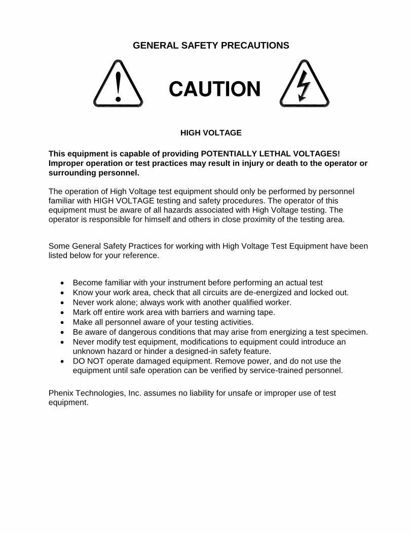
GENERAL SAFETY PRECAUTIONS
HIGH VOLTAGE
This equipment is capable of providing POTENTIALLY LETHAL VOLTAGES!
Improper operation or test practices may result in injury or death to the operator or
surrounding personnel. The operation of High Voltage test equipment should only be performed by personnel familiar with HIGH VOLTAGE testing and safety procedures. The operator of this equipment must be aware of all hazards associated with High Voltage testing. The operator is responsible for himself and others in close proximity of the testing area.
Some General Safety Practices for working with High Voltage Test Equipment have been listed below for your reference.
Become familiar with your instrument before performing an actual test
Know your work area, check that all circuits are de-energized and locked out.
Never work alone; always work with another qualified worker.
Mark off entire work area with barriers and warning tape.
Make all personnel aware of your testing activities.
Be aware of dangerous conditions that may arise from energizing a test specimen.
Never modify test equipment, modifications to equipment could introduce an unknown hazard or hinder a designed-in safety feature.
DO NOT operate damaged equipment. Remove power, and do not use the equipment until safe operation can be verified by service-trained personnel.
Phenix Technologies, Inc. assumes no liability for unsafe or improper use of test equipment.

1-1
1. PRODUCT INFORMATION
WARNING: Contact with the test leads on this equipment can cause harmful or fatal
electrical shock. Do not touch test leads while a test is in process.
SAFETY AND CAUTION NOTES
1. Contact with the test leads on this equipment can cause harmful or fatal electrical shock. Do not touch test leads
while a test is in process.
2. Insure that the unit is properly grounded before proceeding with a test.
3. Turn the unit off before reaching inside. Damage to the unit and hazardous shock to personnel will result if this procedure is not followed.
4. Insure that the equipment to be tested is de-energized and properly isolated.
5. Insure that the equipment to be tested has been properly grounded using a high voltage grounding stick and rubber gloves.
6. Insure that barriers and warning signs are erected in order that personnel in the test area are protected. Use an assistant operator where appropriate to keep non-essential personnel away from the test site.
7. When testing cables, the conductors at the distant end should be isolated from each other and taped.
8. When testing a faulted cable, it is advisable to first make an insulation resistance measurement before proceeding with the high voltage test.
9. Use care to avoid damaging the unit during disassembly and re-assembly procedures.
10. This unit should only be operated by someone familiar with high voltage testing and safety procedures.
DESCRIPTION
The PM15-4A unit is capable of producing regulated voltages as high as 15 kV DC into a variety of insulated electrical apparatus. The unit will measure leakage current flow through (or insulation resistance levels of) the ground insulation of the test sample. Leakage current as low as 1nA DC and as high as 4,000 microamperes DC can be read directly from the unit’s front panel meter. Insulation resistance values up to 15,000,000 megohms may be read at the maximum test voltage of 15 kV DC. The PM15-4A contains an internal discharge circuit which will fully discharge any load within the specifications given on the unit and test objects (See Specs Page). Under all test conditions, except capacitance measurement, discharges will complete within 200ms upon ending a test. Discharge of capacitance up to 15µF will take up to 1 second and any load greater than 15µF requires use of a discharge stick to verify that each load has been fully discharged before disconnecting leads.
PRODUCT INFORMATION
The unit incorporates an Overcurrent trip which responds after a 15 second delay to de-energize the high voltage power supply if such a condition is encountered. The delay is necessary to allow for charging time of capacitive loads. The level of sensitivity at which trip-out will occur is controlled in the Setup screen. The trip setting adjusts from 1µA to 4000µA. Overcurrent trip will automatically shut off HV output. If current trip is not set low enough, no current trip will occur even if output is shorted. The Overcurrent trip setting adjustment is available for the Insulation Resistance (I.R.), Polarization Index (P.I.), and Dielectric Absorption Ratio (D.A.R.) tests. Setting Overcurrent trip to the max current of 4000µA (4mA) will effectively bypass the Overcurrent trip feature. The Overcurrent trip can also be bypassed by leaving the max current field blank.
1-2
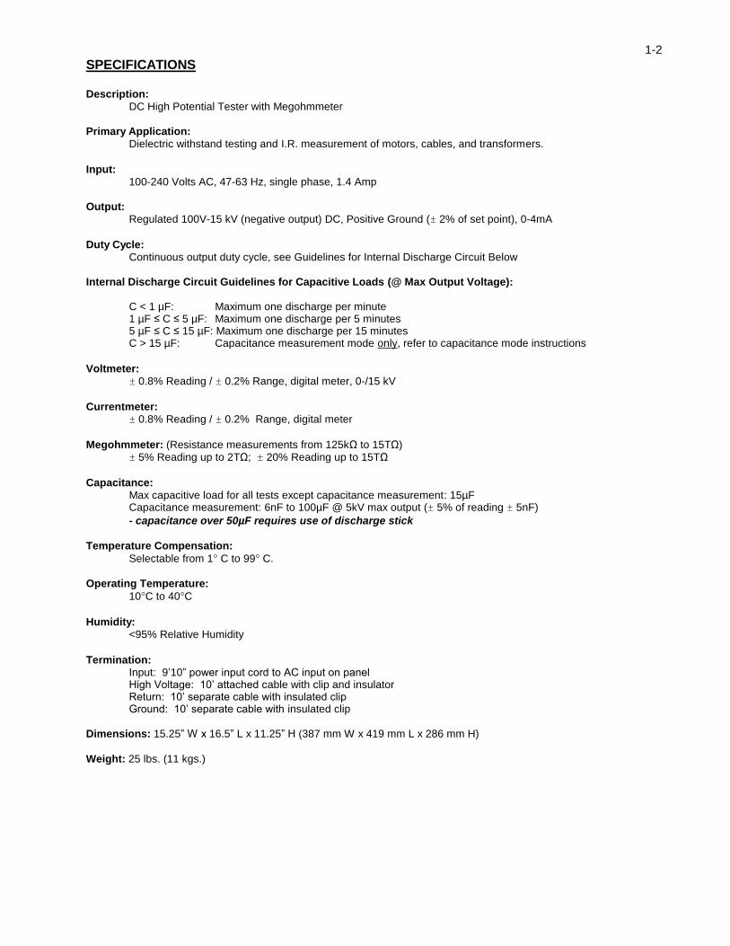
SPECIFICATIONS Description: DC High Potential Tester with Megohmmeter
Primary Application: Dielectric withstand testing and I.R. measurement of motors, cables, and transformers.
Input: 100-240 Volts AC, 47-63 Hz, single phase, 1.4 Amp
Output: Regulated 100V-15 kV (negative output) DC, Positive Ground (± 2% of set point), 0-4mA
Duty Cycle: Continuous output duty cycle, see Guidelines for Internal Discharge Circuit Below
Internal Discharge Circuit Guidelines for Capacitive Loads (@ Max Output Voltage):
C < 1 µF: Maximum one discharge per minute 1 µF ≤ C ≤ 5 µF: Maximum one discharge per 5 minutes 5 µF ≤ C ≤ 15 µF: Maximum one discharge per 15 minutes C > 15 µF: Capacitance measurement mode only, refer to capacitance mode instructions
Voltmeter: ± 0.8% Reading / ± 0.2% Range, digital meter, 0-/15 kV
Currentmeter: ± 0.8% Reading / ± 0.2% Range, digital meter
Megohmmeter: (Resistance measurements from 125kΩ to 15TΩ) ± 5% Reading up to 2TΩ; ± 20% Reading up to 15TΩ
Capacitance: Max capacitive load for all tests except capacitance measurement: 15µF Capacitance measurement: 6nF to 100µF @ 5kV max output (± 5% of reading ± 5nF)
- capacitance over 50µF requires use of discharge stick
Temperature Compensation:
Selectable from 1 C to 99 C.
Operating Temperature:
10C to 40C
Humidity: <95% Relative Humidity
Termination: Input: 9’10” power input cord to AC input on panel High Voltage: 10’ attached cable with clip and insulator Return: 10’ separate cable with insulated clip Ground: 10’ separate cable with insulated clip
Dimensions: 15.25” W x 16.5” L x 11.25” H (387 mm W x 419 mm L x 286 mm H)
Weight: 25 lbs. (11 kgs.)
2-1
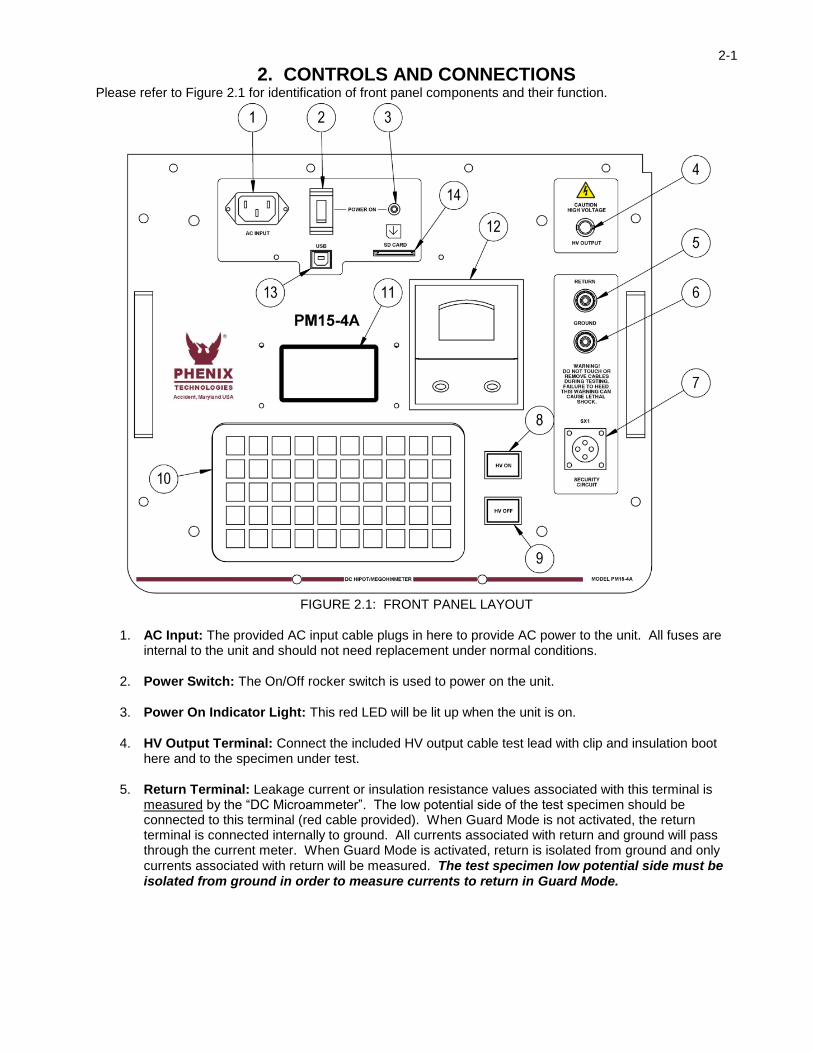
2. CONTROLS AND CONNECTIONS Please refer to Figure 2.1 for identification of front panel components and their function.
FIGURE 2.1: FRONT PANEL LAYOUT
1. AC Input: The provided AC input cable plugs in here to provide AC power to the unit. All fuses are internal to the unit and should not need replacement under normal conditions.
2. Power Switch: The On/Off rocker switch is used to power on the unit.
3. Power On Indicator Light: This red LED will be lit up when the unit is on.
4. HV Output Terminal: Connect the included HV output cable test lead with clip and insulation boot here and to the specimen under test.
5. Return Terminal: Leakage current or insulation resistance values associated with this terminal is measured by the “DC Microammeter”. The low potential side of the test specimen should be connected to this terminal (red cable provided). When Guard Mode is not activated, the return terminal is connected internally to ground. All currents associated with return and ground will pass through the current meter. When Guard Mode is activated, return is isolated from ground and only currents associated with return will be measured. The test specimen low potential side must be isolated from ground in order to measure currents to return in Guard Mode.

2-2
6. Ground Terminal: This terminal is to be connected to the facility ground (black cable provided). Leakage current or insulation resistance values associated with this binding post terminal may be either measured by the “DC Microammeter” or bypassed around the “DC Microammeter” depending on the state of the Guard Mode. If the low potential side of the test specimen connected to Return cannot or will not be isolated from ground, Guard Mode cannot be used or the current meter will not function properly.
7. SX1 Security Circuit: This series circuit must be closed in order to activate High Voltage. An external plug is included to close this circuit or an external customer supplied circuit such as a door interlock of a testing room can be connected to it for use.
8. HV On Push Button: Push this button for HV test when prompted by the onboard display.
9. HV Off Push Button: Push this button to turn off High Voltage to end testing.
10. Keypad: Keyboard to enter information on test data and to navigate the User Interface.
11. Display: Displays User Interface menus and test results.
12. Printer: Used to print test reports and results of HV testing.
13. USB Port: Used to connect the test set to a PC for Data Acquisition using Phenix Windows Test Software (Under Development).
14. SD Card Slot: Used to save test data to an SD Card.
3-1
3. SETUP INSTRUCTIONS
INITIAL CHARGING
Before using the PM15-4A for the first time, perform an initial charging of the batteries as follows: 1. Make sure the main power switch is in the off position. 2. Plug in the supplied AC power cord and connect to the appropriate AC Power Source. 3. The unit will charge automatically once plugged in and will fully charge in 3 hours.
SETUP Set up the unit as follows: 4. Turn the main Power switch to off.
5. Make necessary grounding connections.
6. Assure that test specimen is non-energized, discharged, and properly isolated before proceeding.
Connect the test leads to the specimen to be tested. See Test Lead Connections section for information on connecting the test leads.
7. Connect the “AC Line” cord to the AC Input and to the appropriate “AC Power Source” (see unit specification tag).
8. Connect the SX1 Security Circuit plug (included) to the front panel to complete the circuit for the unit to
enable energizing voltage. Be sure to align the plug with the two pins on the panel-mounted connector. The plug can be disassembled and the contacts used to connect to an appropriate security circuit application such as a security door to the high voltage testing area or similar setup. NOTE: If the security circuit is not connected or loses its connection during a test, the unit will cease its output voltage and display “INTERLOCK OPEN” to alert the operator to check the connection status of the security circuit.
TEST LEAD CONNECTIONS
An understanding of the function of the two current return terminals (“Return” and “Ground”) on the unit will allow the operator to properly connect the test leads for a variety of configurations. The following points should be kept in mind when determining the proper connections for a given test requirement; (see Page 3-3 and 3-4 for further illustration at the end of the Set Up and Operation Section). Assure that test specimen is non-energized, discharged, and properly isolated before connecting test leads. 1. Always attach the “High Voltage Test Lead” to the “High Potential Side” of the test specimen. 2. Always connect the “Ground” terminal to facility ground for each test.

3-2
TEST LEAD CONNECTIONS (continued) 3. In “Normal Mode”, current on the “Return” and the “Ground” terminal is measured by the “DC
Microammeter.”
4. If the “Guard Mode” is activated, current flowing through only the test lead attached to the “Return” terminal on the unit will be measured by the “DC Microammeter”, unless the specimen return is not isolated from ground in which case the currentmeter will be inoperative.
5. Current flowing through the test lead attached to the “Ground” terminal on the unit will be measured by
the “DC Microammeter” only when “Normal Mode” is activated. Ground current associated with the “Ground” terminal will not be measured when “Guard” Mode is activated.
6. To use the “Guard Mode”, the specimen must be isolated from ground. If the low potential side of the
specimen will not or cannot be isolated from ground, the “Guard Mode” cannot be used. 7. The use of appropriately rated discharge and grounding devices is recommended to ensure that the test
object is fully discharged and grounded before removing leads after testing is complete. A minimum discharge time which is approximately 4 times that of the voltage application duration is recommended.
SPECIMEN SETUP CAUTION
Sensitivity Effects of Measuring High Resistance In cases where high voltage electrical test equipment is being used to measure high resistance values of Megohms or higher, any change in the voltage field during a test will cause a change in the capacitance that the meter sees and faulty readings may occur. It is because of this phenomenon related to high resistance measurement methods that any movement of personnel (including operator movement), movement of other equipment, or equipment leads within the vicinity will cause changes in resistance readings seen on the display of the PM15-4A. This effect is greatest at the maximum resistance values that the PM15-4A is capable of measuring, as well as timed tests. It is strongly recommended that a stable test set up is ensured for obtaining the most accurate readings.

3-3
NOTES ON THE USE OF GUARD AND GROUND
NORMAL MODE CONFIGURATION In this configuration the Return and Ground are connected together with a relay internal to the Test Set. Both stray leakage to earth ground and leakage through the Test Specimen are indicated on the current meter. This configuration should be used if it is not possible to isolate the return side of the Test Specimen from earth ground.

3-4
NOTES ON THE USE OF GUARD AND GROUND
GUARD MODE CONFIGURATION In this configuration Ground current is bypassed with a relay internal to the Test Set. Any current associated
with the Return is indicated on the current meter. Any current associated with the Ground bypasses the current meter. Leakage current through the test specimen is indicated on the current meter. Stray leakage to earth ground is not indicated on the current meter. This configuration cannot be used if it is not possible to isolate the return side of the Test Specimen from earth ground.

4-1
4. OPERATION INSTRUCTIONS Turn the unit on by pressing the Power switch. The Power On indicator light will illuminate and remain on. The Splash Screen (Figure 1) will appear momentarily and be followed by the Main Menu Screen.
TECHNOLOGIES
PHENIX
FIGURE 1: Splash Screen
FIGURE 2: Main Menu
From the Main Menu (Figure 2), there are 7 options displayed. The first 5 options are the different tests that the PM15-4A is capable of running. The last two functions are system tools to monitor the battery power and calibrate the unit itself. Simply press the number corresponding to the menu choice using the keypad to progress through the interface. The Battery Info selection is discussed under Care and Maintenance, Section 5.

4-2
4.1 TEST METHODS
4.1.1 Insulation Resistance Test
FIGURE 3: Insulation Resistance Test ID Screen
Enter an alphanumeric test identification (or leave blank) and press enter.
FIGURE 4: Insulation Resistance Test Setup Screen
The Insulation Resistance (I.R.) Test Setup Screen (Figure 4) displays prompts for test time in minutes, maximum voltage to apply, and maximum allowed current for the Overcurrent Trip. Type in test time, in minutes (1-60), or leave blank for continuous testing, then press enter. Proceed with voltage and current in the listed units and press enter to confirm entry. Press enter to proceed to the Temperature Compensation Screen.
FIGURE 5: Temperature Compensation Setup Screen
At the Temperature Compensation Setup Screen (Figure 5), the operator can choose to activate the internal buzzer to sound during the test. Inputs are Y for buzzer on and N for buzzer off. Users can then define a base temperature to correct resistance measurements to, as well as the actual temperature of the test object. These fields must be completed, as leaving them blank does not bypass the temperature compensation function of the unit. It is recommended not to correct to a temperature more than ± 20°C from the test objects temperature, as this could cause significant error in the resistance reading. Once the Temperature Compensation screen is filled out, press Enter to bring up the HV Waiting Screen. SPECIAL NOTE ON TEMPERATURE EFFECTS: Even the best insulation has a small amount of resistive leakage current. With aging and deteriorating of some insulation system (motors, transformers and paper oil insulated cables), this leakage current will increase, which can aid in assessing the quality and remaining lifetime of the insulation system. In order to achieve the most consistent results it is important to correct the test object temperature to a standard temperature, usually (40°C or 68°F). The PM15-4A has the capability to perform this calculation automatically by entering the test object temperature. The built in printer function allows the operator to document the

4-3
results with a date-time stamp showing both the Raw test results without temperature correction as well as the Corrected final value side by side.
FIGURE 6: HV Waiting Screen – Normal Mode
The HV Waiting Screen (Figure 6) acts as a standby screen, allowing the operator one final chance to examine the test setup for any discrepancies before activating high voltage. In this screen, the display reads that the PM15-4A is in Normal Mode. Pressing “G” on the keypad toggles between Normal Mode and Guard Mode Configuration. (See Figure 7)
FIGURE 7: HV Waiting Screen – Guard Mode
The screen will display the status of the Guard Mode as shown in Figure 7 once G is pressed to toggle out of Normal Mode and into Guard Mode operation. In addition, if the security circuit is disconnected, “INTERLOCK OPEN” will appear at this screen (See Figure 8), disabling the high voltage until the security circuit is closed.
Figure 8: HV Waiting Screen – Security Circuit Open
The HV Waiting Screen will display the status message “INTERLOCK OPEN” if the security circuit is not closed on the test set. This status message will appear at the HV Waiting Screen if an open Security Circuit is detected regardless of what operation mode the PM15-4A is set to (Normal or Guard). If this message is seen, check the security circuit for loose connections or replace the SX1 plug onto the front panel to close the security circuit. Press the red HV ON push button to activate the high voltage test. The I.R. Testing Screen will be displayed.
4-4
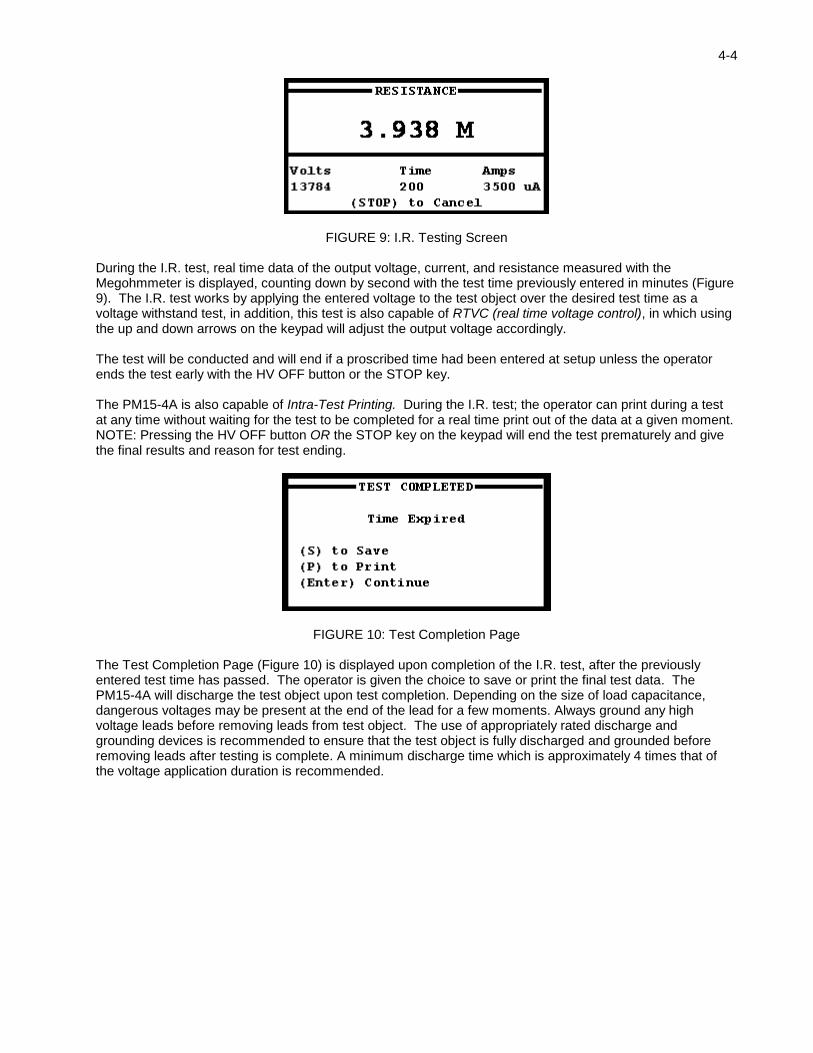
FIGURE 9: I.R. Testing Screen
During the I.R. test, real time data of the output voltage, current, and resistance measured with the Megohmmeter is displayed, counting down by second with the test time previously entered in minutes (Figure 9). The I.R. test works by applying the entered voltage to the test object over the desired test time as a voltage withstand test, in addition, this test is also capable of RTVC (real time voltage control), in which using the up and down arrows on the keypad will adjust the output voltage accordingly. The test will be conducted and will end if a proscribed time had been entered at setup unless the operator ends the test early with the HV OFF button or the STOP key. The PM15-4A is also capable of Intra-Test Printing. During the I.R. test; the operator can print during a test at any time without waiting for the test to be completed for a real time print out of the data at a given moment. NOTE: Pressing the HV OFF button OR the STOP key on the keypad will end the test prematurely and give the final results and reason for test ending.
FIGURE 10: Test Completion Page
The Test Completion Page (Figure 10) is displayed upon completion of the I.R. test, after the previously entered test time has passed. The operator is given the choice to save or print the final test data. The PM15-4A will discharge the test object upon test completion. Depending on the size of load capacitance, dangerous voltages may be present at the end of the lead for a few moments. Always ground any high voltage leads before removing leads from test object. The use of appropriately rated discharge and grounding devices is recommended to ensure that the test object is fully discharged and grounded before removing leads after testing is complete. A minimum discharge time which is approximately 4 times that of the voltage application duration is recommended.

4-5
Figure 11: Insulation Resistance Test Results Sample Printout Figure 11 shows a sample printout of the results of an Insulation Resistance Test. This printout reflects I.R. results of a one-minute duration test with output voltage of 8kV under Guard Mode operation.

4-6
4.1.2 Polarization Index Test
FIGURE 12: Polarization Index Test ID Screen
Enter an alphanumeric test identification (or leave blank) and press enter.
When testing objects with large capacitance, it may take a considerable amount of time for the charging current to approach zero. Therefore it also may take considerable time before the IR test returns a true resistance reading. The Polarization Index records the current over a 10-minute interval by taking a reading every 60 seconds. By making multiple current measurements over time the problem of the time dependant currents is minimized. Instead of looking for an absolute resistance reading the PI test looks for a trend. The final PI ratio is automatically calculated at the end of the test and a hardcopy of the test results may be printed out or saved to an SD card. PI values above 2 indicate good insulation, values between 1 and 2 indicate marginally acceptable insulation, and values less than 1 indicate poor insulation.
FIGURE 13: Polarization Index Setup Screen
At the Polarization Index (P.I.) Setup Screen (Figure 13), enter maximum volts and MicroAmps; the P.I. test runs for ten minutes, so maximum time is not displayed to be entered. Then press Enter to proceed through the Buzzer Option Screen. (Figure 14)
FIGURE 14: Buzzer Option Screen
Choose whether to enable HV warning buzzer then press enter to bring up the HV ON Waiting Screen to apply high voltage (Figure 15).
4-7
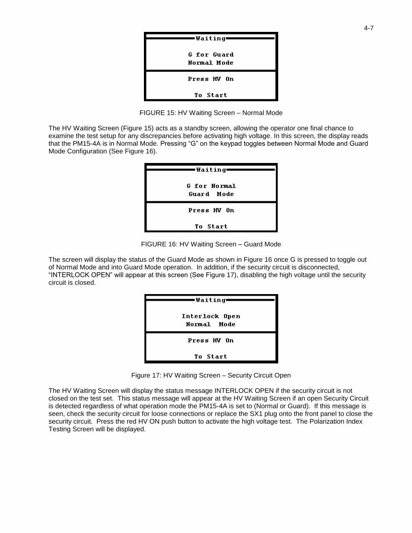
FIGURE 15: HV Waiting Screen – Normal Mode
The HV Waiting Screen (Figure 15) acts as a standby screen, allowing the operator one final chance to examine the test setup for any discrepancies before activating high voltage. In this screen, the display reads that the PM15-4A is in Normal Mode. Pressing “G” on the keypad toggles between Normal Mode and Guard Mode Configuration (See Figure 16).
FIGURE 16: HV Waiting Screen – Guard Mode
The screen will display the status of the Guard Mode as shown in Figure 16 once G is pressed to toggle out of Normal Mode and into Guard Mode operation. In addition, if the security circuit is disconnected, “INTERLOCK OPEN” will appear at this screen (See Figure 17), disabling the high voltage until the security circuit is closed.
Figure 17: HV Waiting Screen – Security Circuit Open
The HV Waiting Screen will display the status message INTERLOCK OPEN if the security circuit is not closed on the test set. This status message will appear at the HV Waiting Screen if an open Security Circuit is detected regardless of what operation mode the PM15-4A is set to (Normal or Guard). If this message is seen, check the security circuit for loose connections or replace the SX1 plug onto the front panel to close the security circuit. Press the red HV ON push button to activate the high voltage test. The Polarization Index Testing Screen will be displayed.

4-8
FIGURE 18: Polarization Index Testing Screen
The Polarization Index Testing Screen (Figure 18) will display during the duration of the P.I. test. Real time data of the output voltage, current, and resistance measured with the Megohmmeter is displayed. The Intra-Test Printing function works differently during the P.I. test. If “P” is depressed during a test, the printer will print resistance results every minute until the test is complete. Otherwise, pressing “P” at the Test Completion page will print the results of the P.I. test with each of the per-minute results all at once. NOTE: Pressing the HV OFF button OR the STOP key on the keypad will end the test early and bring up the Test Completion Page.
FIGURE 19: Polarization Index Test Completion Page
After the P.I. test is completed, the result is displayed (Figure 19) and the operator may print or save the result. Either printing or saving to the SD Card will give the operator results for every minute in addition to the final PI reading. The PM15-4A will discharge the test object upon test completion. Depending on the size of load capacitance, dangerous voltages may be present at the end of the lead for a few moments. Always ground any high voltage leads before removing leads from test object. The use of appropriately rated discharge and grounding devices is recommended to ensure that the test object is fully discharged and grounded before removing leads after testing is complete. A minimum discharge time which is approximately 4 times that of the voltage application duration is recommended.

4-9
Figure 20: Polarization Index Test Results Sample Printout
Figure 20 shows a sample printout the results of a Polarization Index Test. This printout reflects the P.I. results of a ten-minute test with output voltage of 8kV under Guard Mode operation.

4-10
4.1.3 Capacitance Test
FIGURE 21: CAPACITANCE TEST ID Screen
Enter an alphanumeric test identification (or leave blank) and press enter.
FIGURE 22: Capacitance Setup Screen
At the Capacitance Setup Screen (Figure 22), enter the maximum voltage to be applied in volts (5000V MAX). Press Enter to bring up the option screen for the on-board buzzer. (Figure 23)
FIGURE 23: Buzzer Option Screen
Choose whether to enable HV warning buzzer then press enter to bring up the HV ON Waiting Screen to apply high voltage (Figure 24).

4-11
FIGURE 24: HV Waiting Screen – Normal Mode
The HV Waiting Screen (Figure 24) acts as a standby screen, allowing the operator one final chance to examine the test setup for any discrepancies before activating high voltage. In this screen, the display reads that the PM15-4A is in Normal Mode. Pressing “G” on the keypad toggles between Normal Mode and Guard Mode Configuration. (See Figure 25)
FIGURE 25: HV Waiting Screen – Guard Mode
The screen will display the status of the Guard Mode as shown in Figure 25 once G is pressed to toggle out of Normal Mode and into Guard Mode operation. In addition, if the security circuit is disconnected, INTERLOCK OPEN will appear at this screen (See Figure 26), disabling the high voltage until the security circuit is closed.
Figure 26: HV Waiting Screen – Security Circuit Open
The HV Waiting Screen will display the status message INTERLOCK OPEN if the security circuit is not closed on the test set. This status message will appear at the HV Waiting Screen if an open Security Circuit is detected regardless of what operation mode the PM15-4A is set to (Normal or Guard). If this message is seen, check the security circuit for loose connections or replace the SX1 plug onto the front panel to close the security circuit. Press the red HV ON push button to activate the high voltage test. The Capacitance Testing Screen will be displayed.
4-12
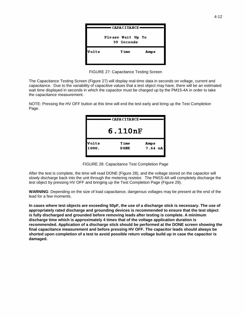
FIGURE 27: Capacitance Testing Screen
The Capacitance Testing Screen (Figure 27) will display real-time data in seconds on voltage, current and capacitance. Due to the variability of capacitive values that a test object may have, there will be an estimated wait time displayed in seconds in which the capacitor must be charged up by the PM15-4A in order to take the capacitance measurement. NOTE: Pressing the HV OFF button at this time will end the test early and bring up the Test Completion Page.
FIGURE 28: Capacitance Test Completion Page After the test is complete, the time will read DONE (Figure 28), and the voltage stored on the capacitor will slowly discharge back into the unit through the metering resistor. The PM15-4A will completely discharge the test object by pressing HV OFF and bringing up the Test Completion Page (Figure 29).
WARNING: Depending on the size of load capacitance, dangerous voltages may be present at the end of the lead for a few moments.
In cases where test objects are exceeding 50µF, the use of a discharge stick is necessary. The use of
appropriately rated discharge and grounding devices is recommended to ensure that the test object
is fully discharged and grounded before removing leads after testing is complete. A minimum
discharge time which is approximately 4 times that of the voltage application duration is
recommended. Application of a discharge stick should be performed at the DONE screen showing the
final capacitance measurement and before pressing HV OFF. The capacitor leads should always be
shorted upon completion of a test to avoid possible return voltage build up in case the capacitor is
damaged.

4-13
FIGURE 29: Test Completion Page
The Test Completion Page (Figure 29) is displayed upon pressing HV OFF after completion of the Capacitance Test, and after applying a discharge stick as prescribed earlier. The operator is given the choice to save or print the final test data. The PM15-4A will discharge the test object upon test completion if the capacitive load is small enough to use the internal discharge circuit. Depending on the size of load capacitance, dangerous voltages may be present at the end of the lead for a few moments. Always ground any high voltage leads before removing leads from test object. The use of appropriately rated discharge and grounding devices is recommended to ensure that the test object is fully discharged and grounded before removing leads after testing is complete. A minimum discharge time which is approximately 4 times that of the voltage application duration is recommended.

4-14
Figure 30: Capacitance Measurement Test Results Sample Printout Figure 30 shows a sample printout of a Capacitance Measurement Test. This printout reflects the results of a Capacitance Measurement Test with 500V output under Guard Mode operation.

4-15
4.1.4 Uniform Step Test
FIGURE 31: Step Test I.D. Screen
Enter an alphanumeric test identification (or leave blank) and press enter. The step test is used to establish trend curves. During the step test, the voltage is raised in discrete steps to a final level. The voltage, current, and resistance are recorded in discrete intervals. Performing step tests over the lifetime of the equipment provides a useful tool for predictive maintenance.
FIGURE 32: Uniform Step Test Setup Screen
At the Uniform Step Test Setup Screen (Figure 32), enter test duration in minutes (1-60), the final voltage and the number of steps to take to reach that final voltage (MAX=20). Press Enter to cycle through the Temperature Compensation Screen (Figure 33).
FIGURE 33: Temperature Compensation Setup Screen
At the Temperature Compensation Setup Screen (Figure 33), the operator can choose to activate the internal buzzer to sound during the test. Inputs are Y for buzzer on and N for buzzer off. Users can then define a base temperature to correct resistance measurements to, as well as the actual temperature of the test object. These fields must be completed, as leaving them blank does not bypass the temperature compensation function of the unit. It is recommended not to correct to a temperature more than ± 20°C from the test objects temperature, as this could cause significant error in the resistance reading. Once the Temperature Compensation screen is filled out, press Enter to bring up the HV Waiting Screen. SPECIAL NOTE ON TEMPERATURE EFFECTS: Even the best insulation has a small amount of resistive leakage current. With ageing and deteriorating of some insulation system (motors, transformers and paper oil insulated cables), this leakage current will increase, which can aid in assessing the quality and remaining lifetime of the insulation system. In order to achieve the most consistent results it is important to correct the test object temperature to a standard

4-16
temperature, usually (40°C or 68°F). The PM15-4A has the capability to perform this calculation automatically by entering the test object temperature. The built in printer function allows the operator to document the results with a date-time stamp showing both the Raw test results without temperature correction as well as the Corrected final value side by side.
FIGURE 34: HV Waiting Screen – Normal Mode
The HV Waiting Screen (Figure 34) acts as a standby screen, allowing the operator one final chance to examine the test setup for any discrepancies before activating high voltage. In this screen, the display reads that the PM15-4A is in Normal Mode. Pressing “G” on the keypad toggles between Normal Mode and Guard Mode Configuration. (See Figure 35)
FIGURE 35: HV Waiting Screen – Guard Mode
The screen will display the status of the Guard Mode as shown in Figure 35 once G is pressed to toggle out of Normal Mode and into Guard Mode operation. In addition, if the security circuit is disconnected, INTERLOCK OPEN will appear at this screen (See Figure 36), disabling the high voltage until the security circuit is closed.
Figure 36: HV Waiting Screen – Security Circuit Open
The HV Waiting Screen will display the status message INTERLOCK OPEN if the security circuit is not closed on the test set. This status message will appear at the HV Waiting Screen if an open Security Circuit is detected regardless of what operation mode the PM15-4A is set to (Normal or Guard). If this message is seen, check the security circuit for loose connections or replace the SX1 plug onto the front panel to close the security circuit. Press the red HV ON push button to activate the high voltage test. The Uniform Step Testing Screen will be displayed.
4-17
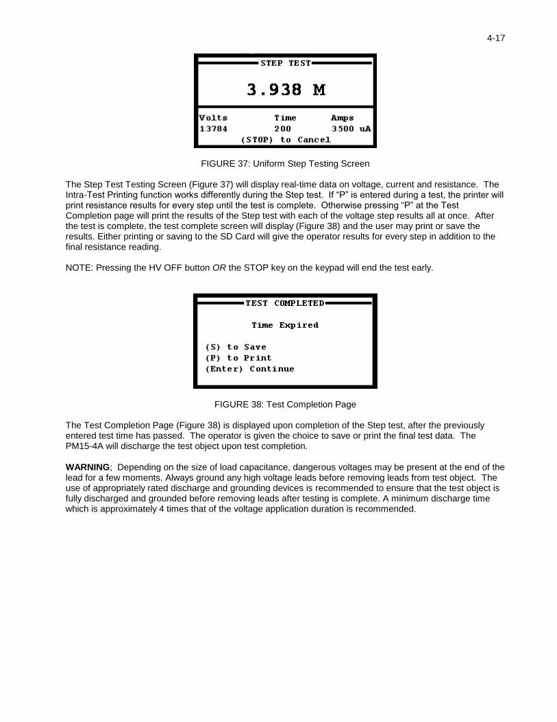
FIGURE 37: Uniform Step Testing Screen
The Step Test Testing Screen (Figure 37) will display real-time data on voltage, current and resistance. The Intra-Test Printing function works differently during the Step test. If “P” is entered during a test, the printer will print resistance results for every step until the test is complete. Otherwise pressing “P” at the Test Completion page will print the results of the Step test with each of the voltage step results all at once. After the test is complete, the test complete screen will display (Figure 38) and the user may print or save the results. Either printing or saving to the SD Card will give the operator results for every step in addition to the final resistance reading. NOTE: Pressing the HV OFF button OR the STOP key on the keypad will end the test early.
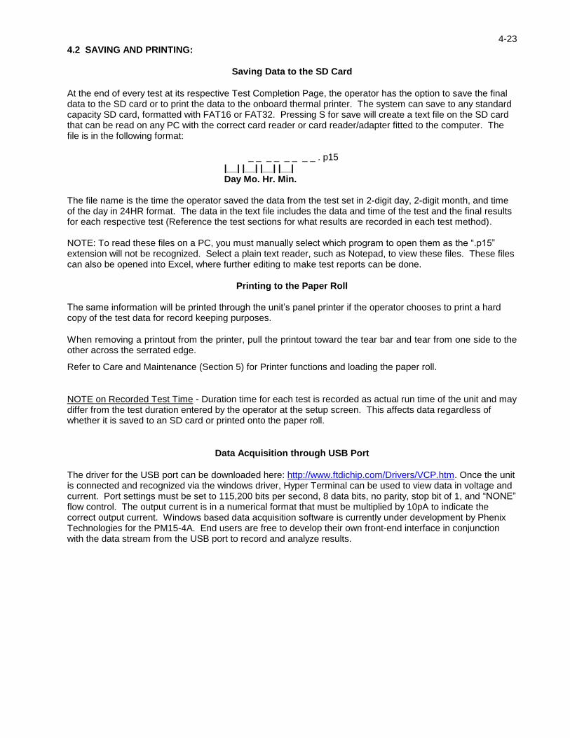
FIGURE 38: Test Completion Page
The Test Completion Page (Figure 38) is displayed upon completion of the Step test, after the previously entered test time has passed. The operator is given the choice to save or print the final test data. The PM15-4A will discharge the test object upon test completion.
WARNING; Depending on the size of load capacitance, dangerous voltages may be present at the end of the lead for a few moments. Always ground any high voltage leads before removing leads from test object. The use of appropriately rated discharge and grounding devices is recommended to ensure that the test object is fully discharged and grounded before removing leads after testing is complete. A minimum discharge time which is approximately 4 times that of the voltage application duration is recommended.

4-18
Figure 39: Uniform Voltage Step Results Test Sample Printout
Figure 39 shows a sample printout of a Uniform Voltage Step Test. This printout reflects the results of a Step Test of 5-minute duration, 15kV max output voltage, and 20 steps of voltage at a uniform 15-second duration each.

4-19
4.1.5 Dielectric Absorption Ratio (D.A.R. Test)
Figure 40: Dielectric Absorption Ratio Test I.D. Screen Enter an alphanumeric test identification (or leave blank) and press enter.
In good insulation systems, it is expected that the insulation resistance increases as the time dependant charging currents approach zero. Generally, insulation systems that are degraded show low resistance values even after a considerable amount of time has elapsed. The time dependant Dielectric Absorption Ratio can provide a good indication whether the insulation system has a problem. By taking a resistance measurement at 30s and a resistance measurement at 60s and calculating the ratio of the two readings, a determination of the insulation quality can be made. Typically D.A.R. values lower than 1.25 warrant further testing and evaluation.
FIGURE 41: Dielectric Absorption Ratio Setup Screen
At the Dielectric Absorption Ratio Setup Screen (Figure 41), enter the maximum voltage to apply and the maximum allowed current for the Overcurrent Trip. Press Enter to cycle through the Temperature Compensation Setup Screen.
FIGURE 42: Temperature Compensation Setup Screen
At the Temperature Compensation Setup Screen (Figure 42), the operator can choose to activate the internal buzzer to sound during the test. Inputs are Y for buzzer on and N for buzzer off. Users can then define a base temperature to correct resistance measurements to, as well as the actual temperature of the test object. These fields must be completed, as leaving them blank does not bypass the temperature compensation function of the unit. It is recommended not to correct to a temperature more than ± 20°C from the test objects temperature, as this could cause significant error in the resistance reading. Once the Temperature Compensation screen is filled out, press Enter to bring up the HV Waiting Screen.

4-20
SPECIAL NOTE ON TEMPERATURE EFFECTS: Even the best insulation has a small amount of resistive leakage current. With ageing and deteriorating of some insulation system (motors, transformers and paper oil insulated cables), this leakage current will increase, which can aid in assessing the quality and remaining lifetime of the insulation system. In order to achieve the most consistent results it is important to correct the test object temperature to a standard temperature, usually (40°C or 68°F). The PM15-4A has the capability to perform this calculation automatically by entering the test object temperature. The built in printer function allows the operator to document the results with a date-time stamp showing both the Raw test results without temperature correction as well as the Corrected final value side by side.
FIGURE 43: HV Waiting Screen – Normal Mode
The HV Waiting Screen (Figure 43) acts as a standby screen, allowing the operator one final chance to examine the test setup for any discrepancies before activating high voltage. In this screen, the display reads that the PM15-4A is in Normal Mode. Pressing G on the keypad toggles between Normal Mode and Guard Mode Configuration (See Figure 44).
FIGURE 44: HV Waiting Screen – Guard Mode
The screen will display the status of the Guard Mode as shown in Figure 44 once G is pressed to toggle out of Normal Mode and into Guard Mode operation. In addition, if the security circuit is disconnected, INTERLOCK OPEN will appear at this screen (See Figure 45), disabling the high voltage until the security circuit is closed.

4-21
Figure 45: HV Waiting Screen – Security Circuit Open
The HV Waiting Screen will display the status message INTERLOCK OPEN if the security circuit is not closed on the test set. This status message will appear at the HV Waiting Screen if an open Security Circuit is detected regardless of what operation mode the PM15-4A is set to (Normal or Guard). If this message is seen, check the security circuit for loose connections or replace the SX1 plug onto the front panel to close the security circuit. Press the red HV ON push button to activate the high voltage test. The Dielectric Absorption Ratio Testing Screen will be displayed.
FIGURE 46: Dielectric Absorption Ratio Testing Screen
The Dielectric Absorption Ratio Testing Screen (Figure 46) will display real-time data on voltage, current and resistance. After the test is complete, the test complete screen will come up (Figure 47) and the user may print or save the results. Either printing or saving to the SD Card will give the operator resistance measurements for every ten seconds in addition to the final Dielectric Absorption Ratio result. The PM15-4A will discharge the test object upon test completion.
WARNING: Depending on the size of load capacitance, dangerous voltages may be present at the end of the lead for a few moments. Always ground any high voltage leads before removing leads from test object. The use of appropriately rated discharge and grounding devices is recommended to ensure that the test object is fully discharged and grounded before removing leads after testing is complete. A minimum discharge time which is approximately 4 times that of the voltage application duration is recommended.
FIGURE 47: Dielectric Absorption Ratio Test Completion Page

4-22
Figure 48: Dielectric Absorption Ratio Test Results Sample Printout
Figure 48 shows a sample printout of a Dielectric Absorption Ratio Test. This printout reflects the results of a D.A.R. test with one-minute duration at 8kV output.
4-23
4.2 SAVING AND PRINTING:
Saving Data to the SD Card
At the end of every test at its respective Test Completion Page, the operator has the option to save the final data to the SD card or to print the data to the onboard thermal printer. The system can save to any standard capacity SD card, formatted with FAT16 or FAT32. Pressing S for save will create a text file on the SD card that can be read on any PC with the correct card reader or card reader/adapter fitted to the computer. The file is in the following format:
_ _ _ _ _ _ _ _ . p15
|__| |__| |__| |__|
Day Mo. Hr. Min. The file name is the time the operator saved the data from the test set in 2-digit day, 2-digit month, and time of the day in 24HR format. The data in the text file includes the data and time of the test and the final results for each respective test (Reference the test sections for what results are recorded in each test method). NOTE: To read these files on a PC, you must manually select which program to open them as the “.p15” extension will not be recognized. Select a plain text reader, such as Notepad, to view these files. These files can also be opened into Excel, where further editing to make test reports can be done.
Printing to the Paper Roll The same information will be printed through the unit’s panel printer if the operator chooses to print a hard copy of the test data for record keeping purposes.
When removing a printout from the printer, pull the printout toward the tear bar and tear from one side to the other across the serrated edge.
Refer to Care and Maintenance (Section 5) for Printer functions and loading the paper roll.
NOTE on Recorded Test Time - Duration time for each test is recorded as actual run time of the unit and may differ from the test duration entered by the operator at the setup screen. This affects data regardless of whether it is saved to an SD card or printed onto the paper roll.
Data Acquisition through USB Port
The driver for the USB port can be downloaded here: http://www.ftdichip.com/Drivers/VCP.htm. Once the unit is connected and recognized via the windows driver, Hyper Terminal can be used to view data in voltage and current. Port settings must be set to 115,200 bits per second, 8 data bits, no parity, stop bit of 1, and “NONE” flow control. The output current is in a numerical format that must be multiplied by 10pA to indicate the correct output current. Windows based data acquisition software is currently under development by Phenix Technologies for the PM15-4A. End users are free to develop their own front-end interface in conjunction with the data stream from the USB port to record and analyze results.

4-24
4.3 SYSTEM TOOLS
The PM15-4A has several pre-programmed system tools for operator use. The available items are listed on the System Setup screen, accessible through the Main Menu. Select the number on the keypad which corresponds with the available options to proceed.
FIGURE 49: System Setup Screen
FIGURE 50: Company Name Entry Screen
At the Company Name Entry Screen, a company name may be entered and saved to memory. Start typing to overwrite the system default setting and press Enter to save changes.
FIGURE 51: Clock Setup Screen
At the Clock Setup Screen, users may enter the time in either 12- or 24-hour format, which will then be displayed when test data is saved and/or printed. Press T to toggle between 12- and 24-hour formats.
4-25
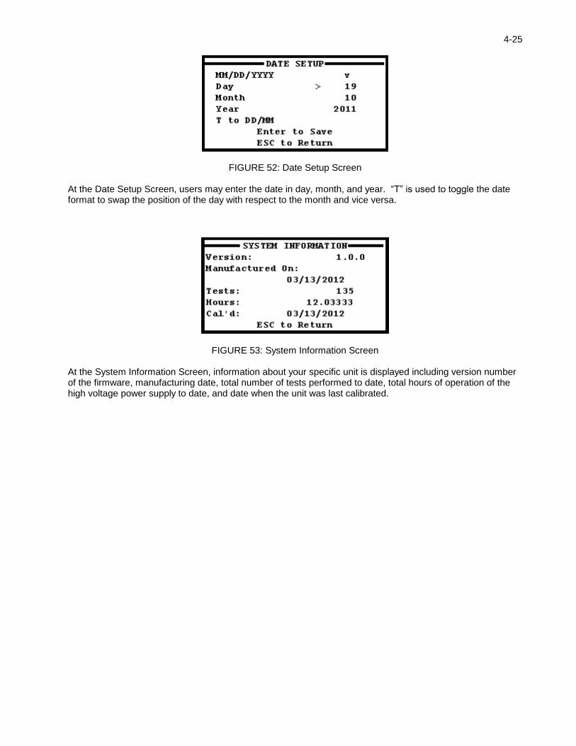
FIGURE 52: Date Setup Screen
At the Date Setup Screen, users may enter the date in day, month, and year. “T” is used to toggle the date format to swap the position of the day with respect to the month and vice versa.
FIGURE 53: System Information Screen
At the System Information Screen, information about your specific unit is displayed including version number of the firmware, manufacturing date, total number of tests performed to date, total hours of operation of the high voltage power supply to date, and date when the unit was last calibrated.
4-26
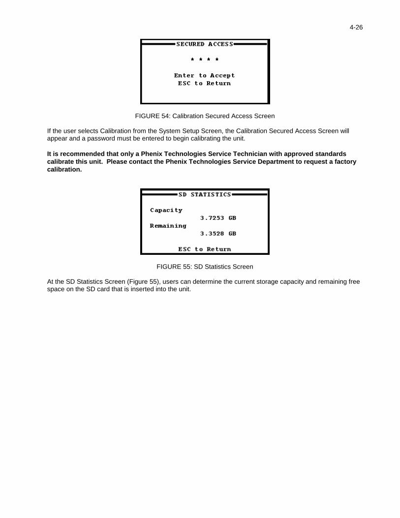
FIGURE 54: Calibration Secured Access Screen
If the user selects Calibration from the System Setup Screen, the Calibration Secured Access Screen will appear and a password must be entered to begin calibrating the unit.
It is recommended that only a Phenix Technologies Service Technician with approved standards
calibrate this unit. Please contact the Phenix Technologies Service Department to request a factory
calibration.
FIGURE 55: SD Statistics Screen
At the SD Statistics Screen (Figure 55), users can determine the current storage capacity and remaining free space on the SD card that is inserted into the unit.

5-1
5. CARE AND MAINTAINANCE
5.1 NI-MH BATTERY MAINTAINANCE NI-MH batteries have a high self-discharge rate. It is therefore recommended to complete a full charge cycle at least once a week. If the batteries become discharged to the point the unit will no longer turn on under battery power, complete a full recharge cycle by plugging the unit in and leaving it plugged in for 3 hours. The Battery Information screen (shown below) will display the batteries’ charge and voltage information. It can be viewed from the Main Menu and pressing “ESC” on the keypad will return the user back to the Main Menu screen.
FIGURE 56: Battery Info Screen
5.2 CLEANING Only the outer surfaces of the case and the front panel of the unit should need cleaning. Use a damp cloth with glass cleaner to wipe clean the front panel surfaces. Take care not to allow cleaning fluid or fluids of any kind to enter through the crevasses of the front panel (ports and connection terminals). The front panel should not need removed under normal circumstances. Do not attempt to vacuum the main chassis.
5.3 PRINTER MAINTENANCE
5.3.1 Power On Self-Test The self-test procedure is initiated by supplying power to the printer while the paper feed button is depressed. When the paper feed button is released a test print will be produced.
5-2
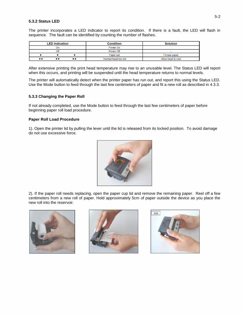
5.3.2 Status LED The printer incorporates a LED indicator to report its condition. If there is a fault, the LED will flash in sequence. The fault can be identified by counting the number of flashes.
After extensive printing the print head temperature may rise to an unusable level. The Status LED will report when this occurs, and printing will be suspended until the head temperature returns to normal levels.
The printer will automatically detect when the printer paper has run out, and report this using the Status LED. Use the Mode button to feed through the last few centimeters of paper and fit a new roll as described in 4.3.3.
5.3.3 Changing the Paper Roll If not already completed, use the Mode button to feed through the last few centimeters of paper before beginning paper roll load procedure.
Paper Roll Load Procedure 1). Open the printer lid by pulling the lever until the lid is released from its locked position. To avoid damage do not use excessive force.
2). If the paper roll needs replacing, open the paper cup lid and remove the remaining paper. Reel off a few centimeters from a new roll of paper. Hold approximately 5cm of paper outside the device as you place the new roll into the reservoir.
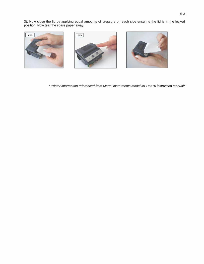
5-3 3). Now close the lid by applying equal amounts of pressure on each side ensuring the lid is in the locked position. Now tear the spare paper away.
* Printer information referenced from Martel Instruments model MPP5510 instruction manual*

6-1
SCHEMATIC
Drawing Number Description 9109081 PM15-4A

7-1
PM15-4A RECOMMENDED SPARE PARTS LIST
Qty.
Phenix
Stock # Item Description
1 1001839 PAPER ROLL * PAPER ROLL FOR PANEL PRINTER MPP5510
1 1077170 PWR CORD 18/3 9’10” RT ANG MOD PWR CORD #37F3354
1 1422150 SW1 * 31-903.2 LENS, EAO RED
1 1422151 SW2 * 31-903.5 LENS, GREEN
2 1420145 SW1-2 * 10-1313.1249 EAO LAMP 28V
1 1590009 BATT. PACK 7 CELL BATTERY PACK
1 1077330 PS2 HV CABLE ASSY 15kVDC 18”
1 30070022 OUTPUT CABLE HV OUTPUT CABLE ASSY (PM15-4A)
1 30080004 RTN CABLE RETURN CABLE ASSY – 10 FT
1 30080005 GND CBL GROUNDING CABLE ASSY – 10 FT

8-1 PARTS ORDERING INFORMATION
Replacement parts are available from Phenix Technologies, Inc. Changes to Phenix Technologies' products are sometimes made to accommodate improved components as they become available, and to give you the benefit of the latest technical improvements developed in our Engineering Department. It is, therefore, important when ordering parts to include the serial number of the unit as well as the part number of the replacement part. When your purchase order is received at our office, a representative of Phenix Technologies will contact you to confirm the current price of the part being ordered. If a part you order has been replaced with a new or improved part, an Applications Engineer will contact you concerning any change in part number. Your order for replacement parts should be sent to:
Service Department
Phenix Technologies, Inc. 75 Speicher Drive
Accident, Maryland 21520
Phone (301) 746-8118 Fax (301) 895-5570
9-1
RETURNED MATERIAL
If for any reason it should become necessary to return this equipment to the factory, the Service Department of Phenix Technologies, Inc. must be given the following information:
Name Plate Information
Model Number Serial Number
Reason for Return Cause of Defect
If Phenix Technologies, Inc. deems return of the part appropriate, it will then issue an "Authorization for Return." If return is not deemed advisable, other inspection arrangements will be made. NOTE: Material received at this plant without the proper authorization shall be held as "Customer's Property" with no service until such time as the proper steps have been taken. Your cooperation is requested in order to ensure prompt service.