Embed Size (px)
Citation preview
Operational ground-based remote sensing of wind:
Radar wind profilers
Data Quality through Improved Standardization of Procedures
V. Lehmann with contributions from: A.Haefele, E.Päschke, R.Leinweber,
S.Cohn, W.Brown and many others
1.RWP networks and data impact in NWP
2.RWP – some fundamentals
3.Accuracy assessment and possibilities for
standardisation
Outline of talk
1.RWP networks and data impact in NWP
2.RWP – some fundamentals
3.Accuracy assessment and possibilities for
standardisation
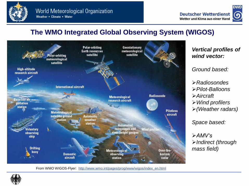
The WMO Integrated Global Observing System (WIGOS)
From WMO WIGOS-Flyer: http://www.wmo.int/pages/prog/www/wigos/index_en.html
Vertical profiles of
wind vector:
Ground based:
Radiosondes
Pilot-Balloons
Aircraft
Wind profilers
(Weather radars)
Space based:
AMV‘s
Indirect (through
mass field)

RWP networks in WIGOS (as of 2013)
Courtesy: Alexander Cress (DWD)
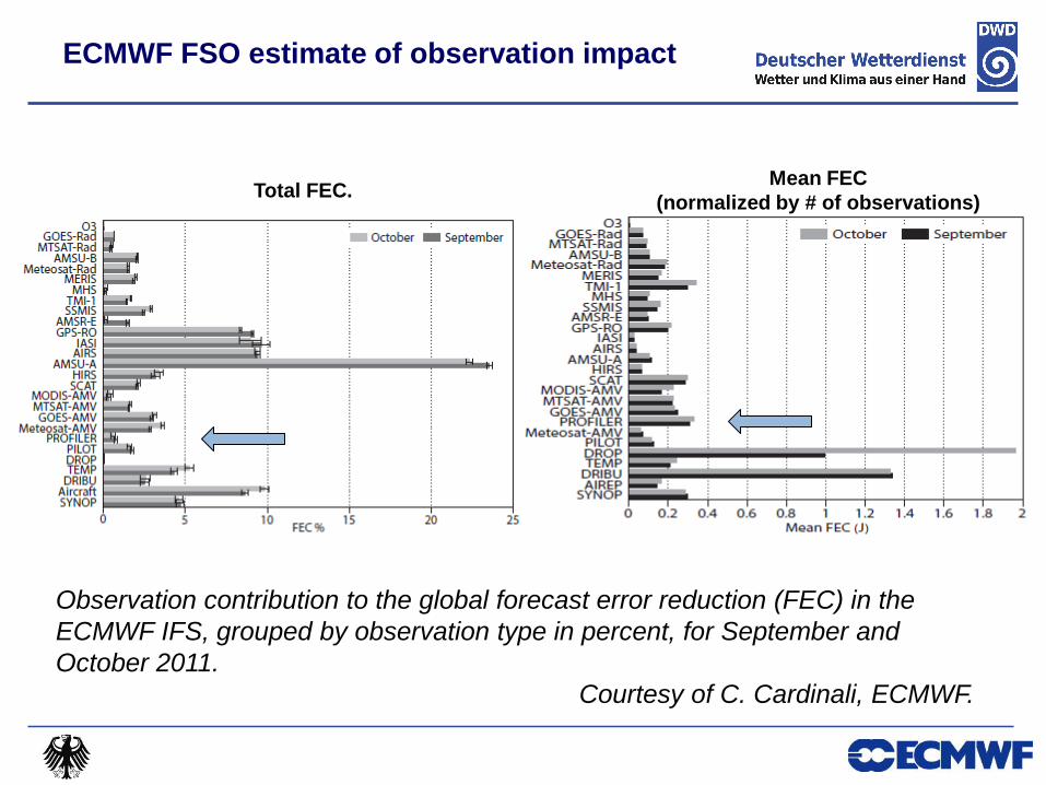
Observation contribution to the global forecast error reduction (FEC) in the
ECMWF IFS, grouped by observation type in percent, for September and
October 2011.
Courtesy of C. Cardinali, ECMWF.
Total FEC. Mean FEC
(normalized by # of observations)
ECMWF FSO estimate of observation impact

Deutscher Wetterdienst UK MetOffice FSO estimate of RWP impact
Reduction of forcast error
measured by global moist
energy norm (u,v,T,p,q)
4 German TEMPs vs.
4 German RWP (482 MHz)
First results from UK MetO
FSO-tool for the period
Aug 22 – Sep 29, 2010
Courtesy:
Richard Marriott
Catherine Gaffard
Ronny Leinweber
Lindenberg RWP impact is 5 times bigger than the
impact of the co-located Radiosonde !

1.RWP networks and data impact in NWP
2.RWP – some fundamentals
3.Accuracy assessment and possibilities for
standardisation
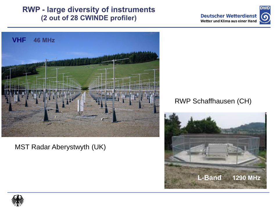
RWP - large diversity of instruments (2 out of 28 CWINDE profiler)
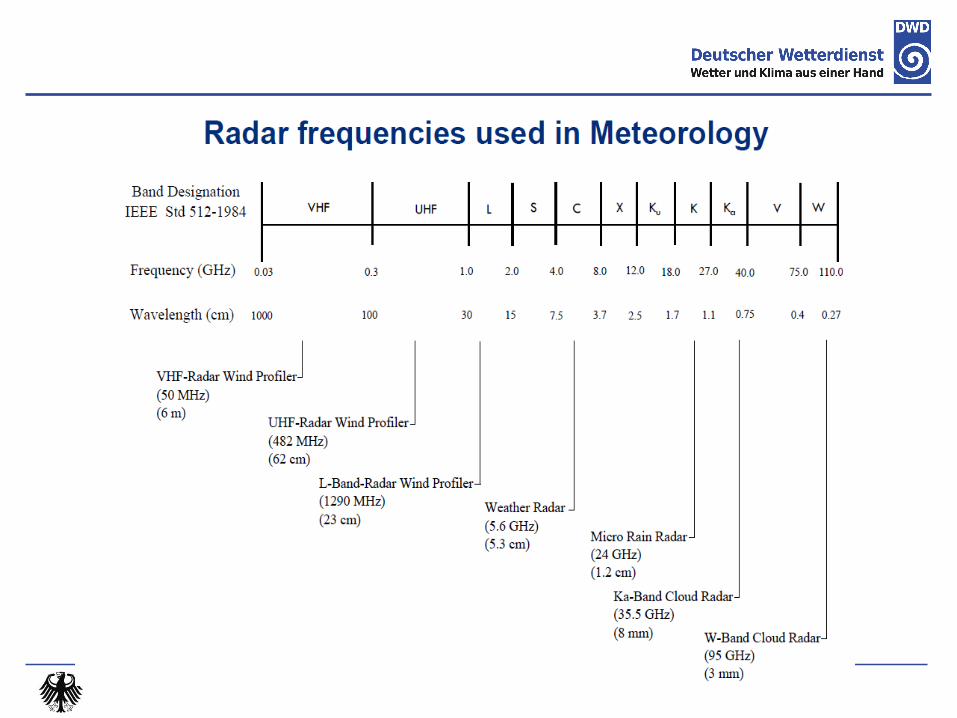
46 MHz
1290 MHz
1290 MHz 1290 MHz
482 MHz
1290 MHz
VHF
L-Band
MST Radar Aberystwyth (UK)
RWP Schaffhausen (CH)
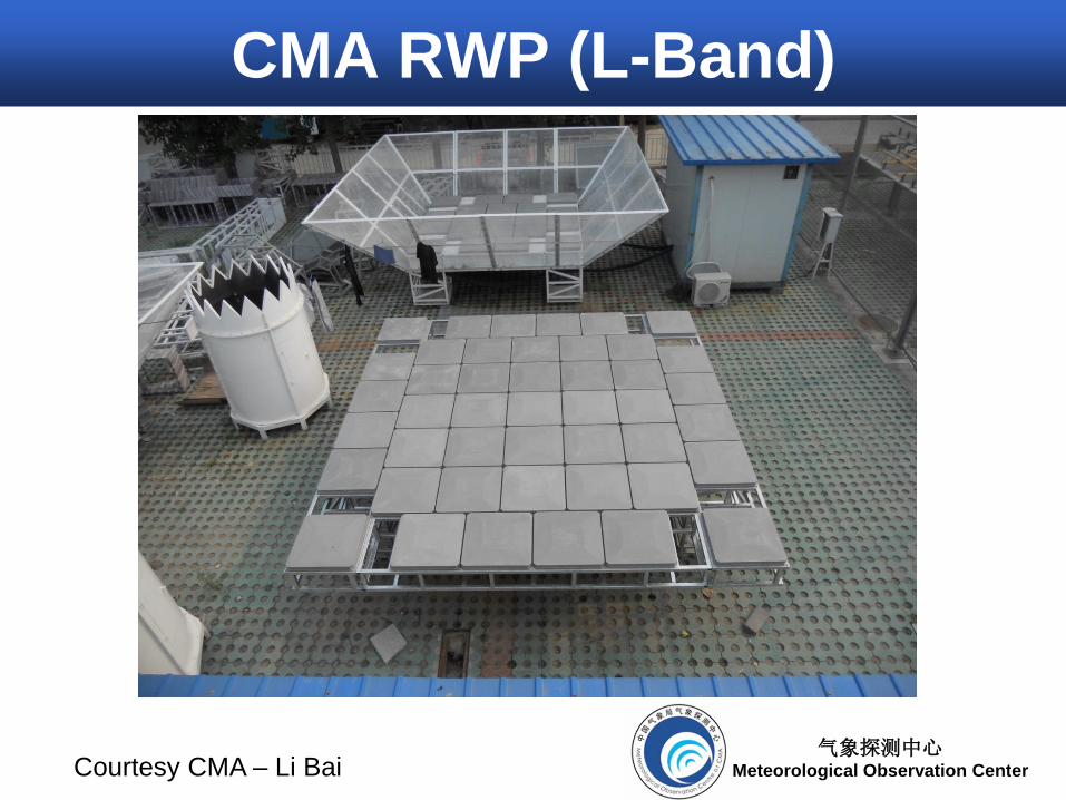
气象探测中心 Meteorological Observation Center
CMA RWP (L-Band)
Courtesy CMA – Li Bai
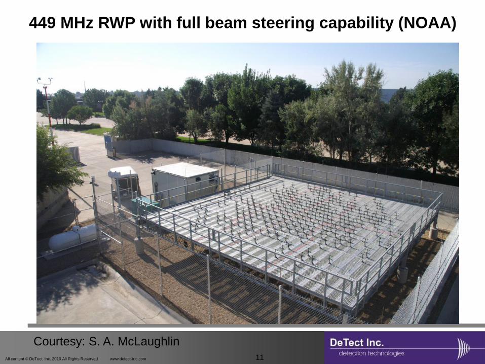
All content © DeTect, Inc. 2010 All Rights Reserved www.detect-inc.com 11
449 MHz RWP with full beam steering capability (NOAA)
Courtesy: S. A. McLaughlin
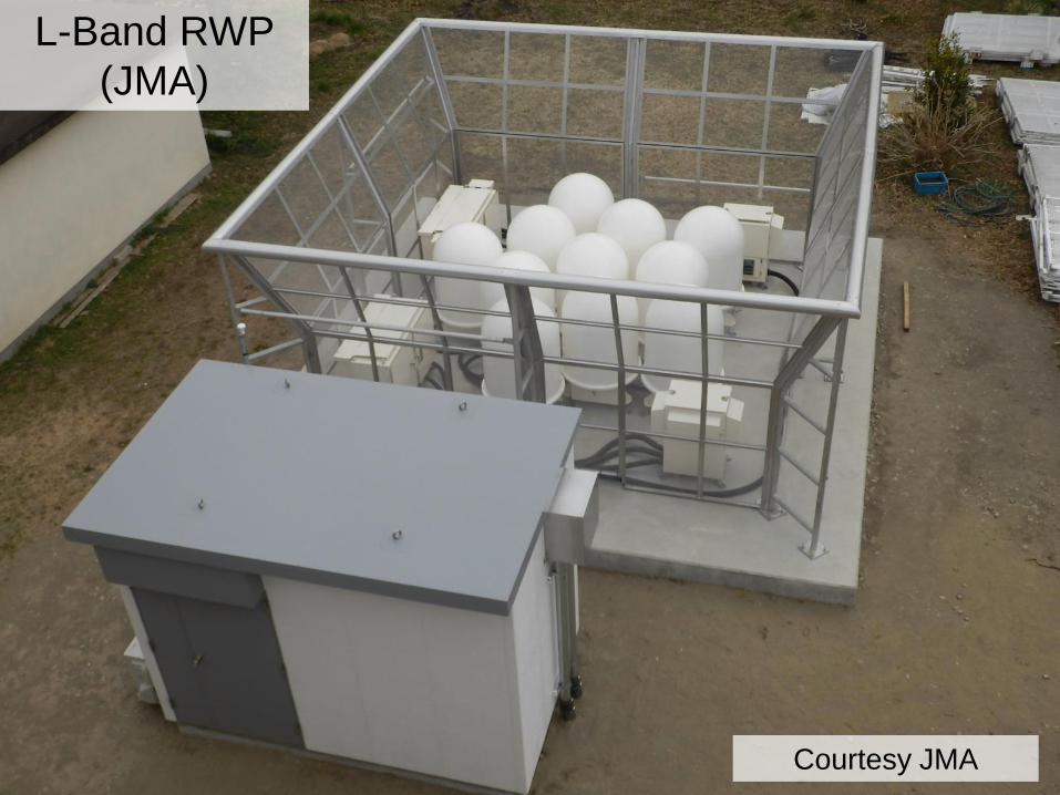
L-Band RWP
(JMA)
Courtesy JMA
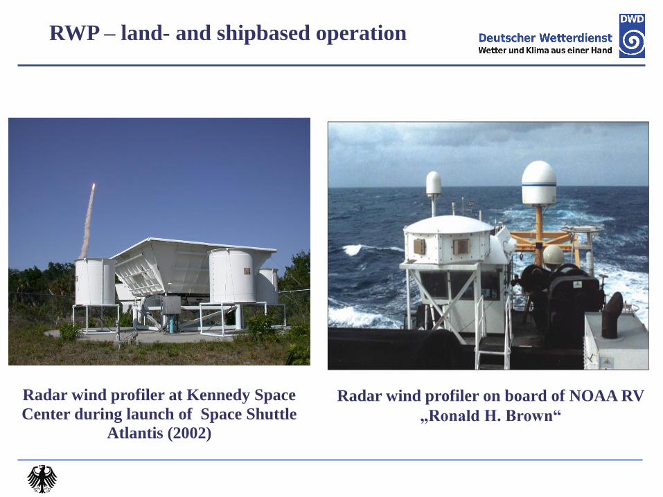
Radar wind profiler at Kennedy Space
Center during launch of Space Shuttle
Atlantis (2002)
Radar wind profiler on board of NOAA RV
„Ronald H. Brown“
RWP – land- and shipbased operation
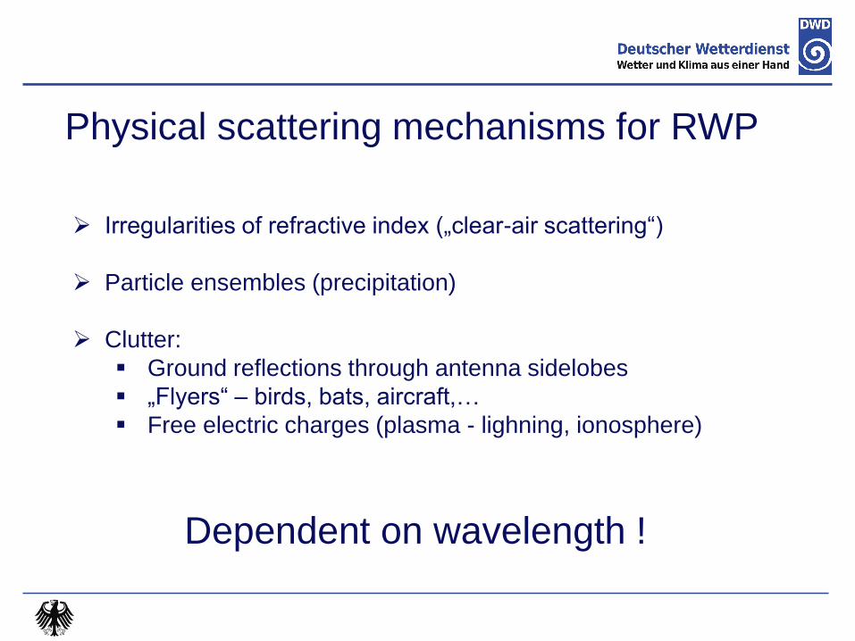
Physical scattering mechanisms for RWP
Irregularities of refractive index („clear-air scattering“)
Particle ensembles (precipitation)
Clutter:
Ground reflections through antenna sidelobes
„Flyers“ – birds, bats, aircraft,…
Free electric charges (plasma - lighning, ionosphere)
Dependent on wavelength !
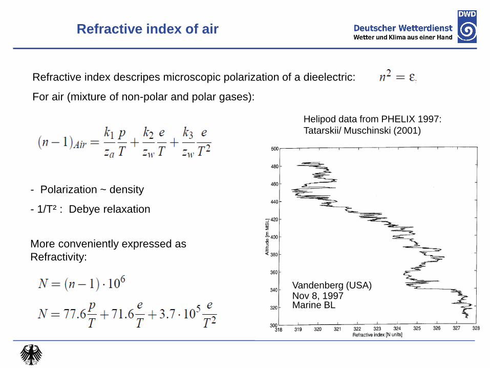
Refractive index of air
Refractive index descripes microscopic polarization of a dieelectric:
For air (mixture of non-polar and polar gases):
More conveniently expressed as
Refractivity:
- Polarization ~ density
- 1/T² : Debye relaxation
Helipod data from PHELIX 1997:
Tatarskii/ Muschinski (2001)
Vandenberg (USA) Nov 8, 1997 Marine BL
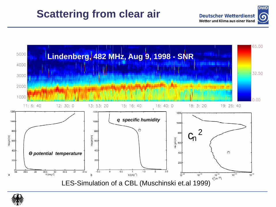
Lindenberg, 482 MHz, Aug 9, 1998 - SNR
LES-Simulation of a CBL (Muschinski et.al 1999)
Θ potential temperature
q specific humidity
cn2
Scattering from clear air
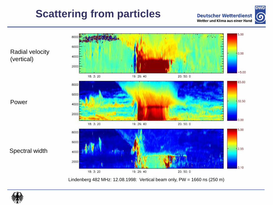
Scattering from particles
Radial velocity
(vertical)
Power
Spectral width
Lindenberg 482 MHz: 12.08.1998: Vertical beam only, PW = 1660 ns (250 m)
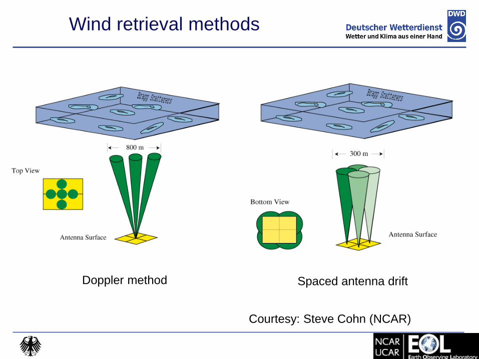
Wind retrieval methods
Doppler method Spaced antenna drift
Courtesy: Steve Cohn (NCAR)

Doppler method (DBS)
Doppler method:
Antenna beam is steered in several directions (min. 3)
Doppler shift is directly estimated
Radial measurements are combined to get wind vector
Pros: Most RWP employ this method
Gives the best height coverage
Method well established
Cons: Assumptions about wind field need to be made
Beam steering required
MMC-2014, 15 – 16 September 2014, Slovenia
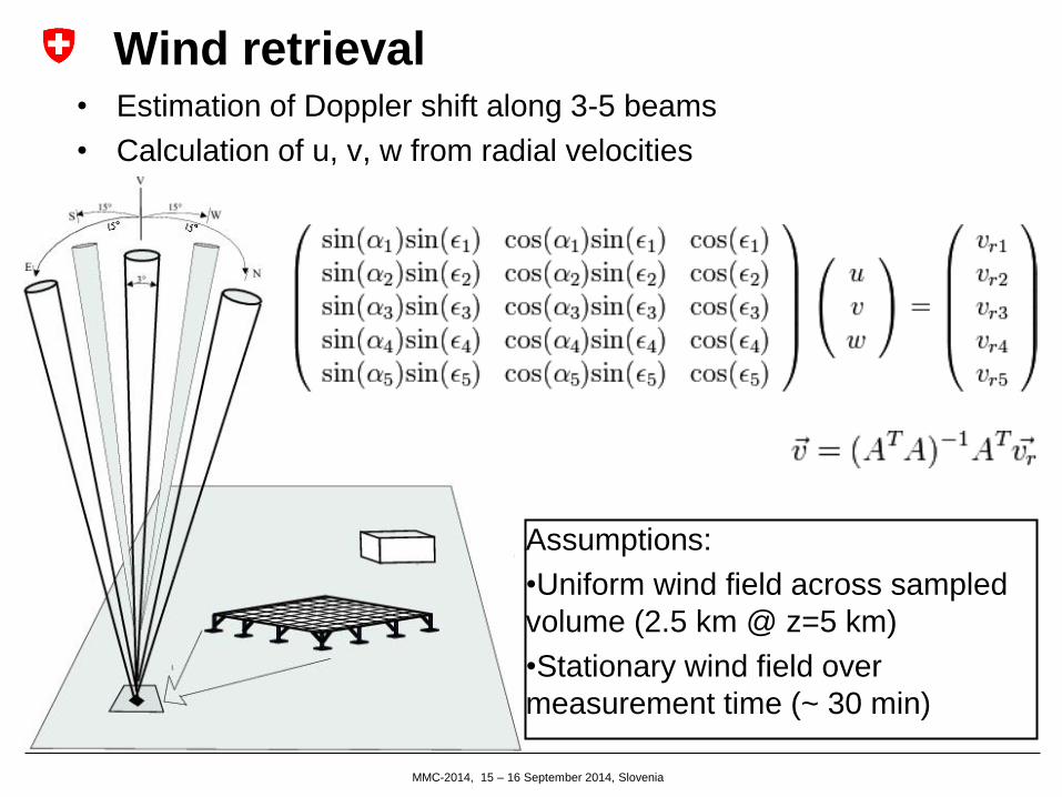
Wind retrieval • Estimation of Doppler shift along 3-5 beams
• Calculation of u, v, w from radial velocities
Assumptions:
•Uniform wind field across sampled
volume (2.5 km @ z=5 km)
•Stationary wind field over
measurement time (~ 30 min)
Spaced antenna (SA) drift method
Vertical beam direction, echoes received with multiple (spaced) antennas
Doppler shift is directly estimated for w
Horizontal wind components from cross-correlation of signals
Pros: Single observation volume – almost no assumptions on wind field
No beam steering required - simpler hardware
Cons: Smaller SNR – lower height coverage
Method has still issues (e.g. wind speed bias ~ 10%)
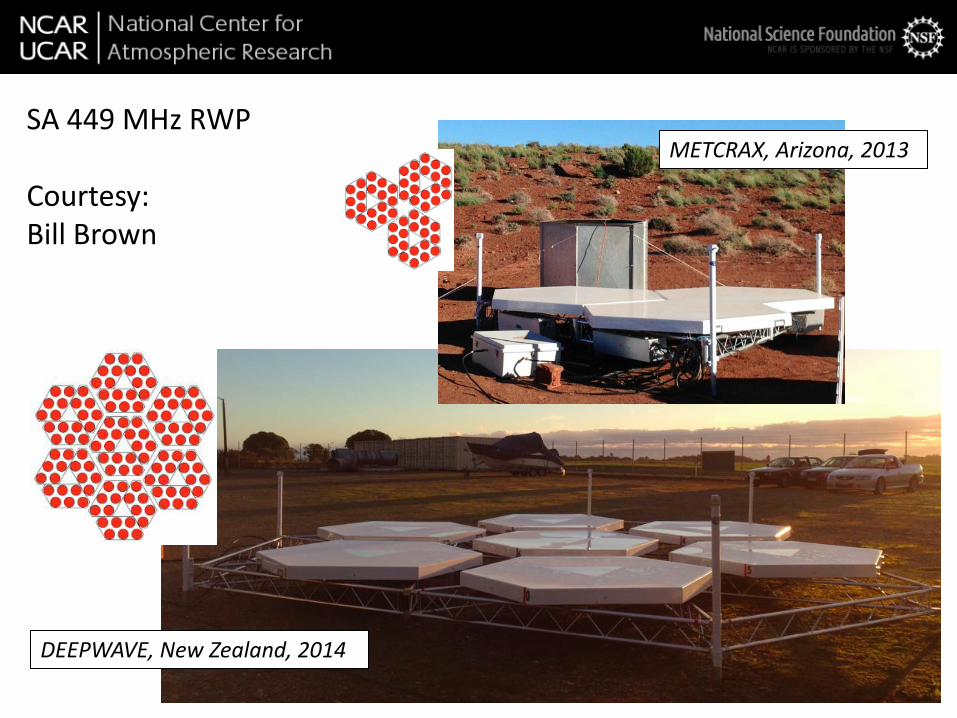
SA 449 MHz RWP Courtesy: Bill Brown
METCRAX, Arizona, 2013
DEEPWAVE, New Zealand, 2014
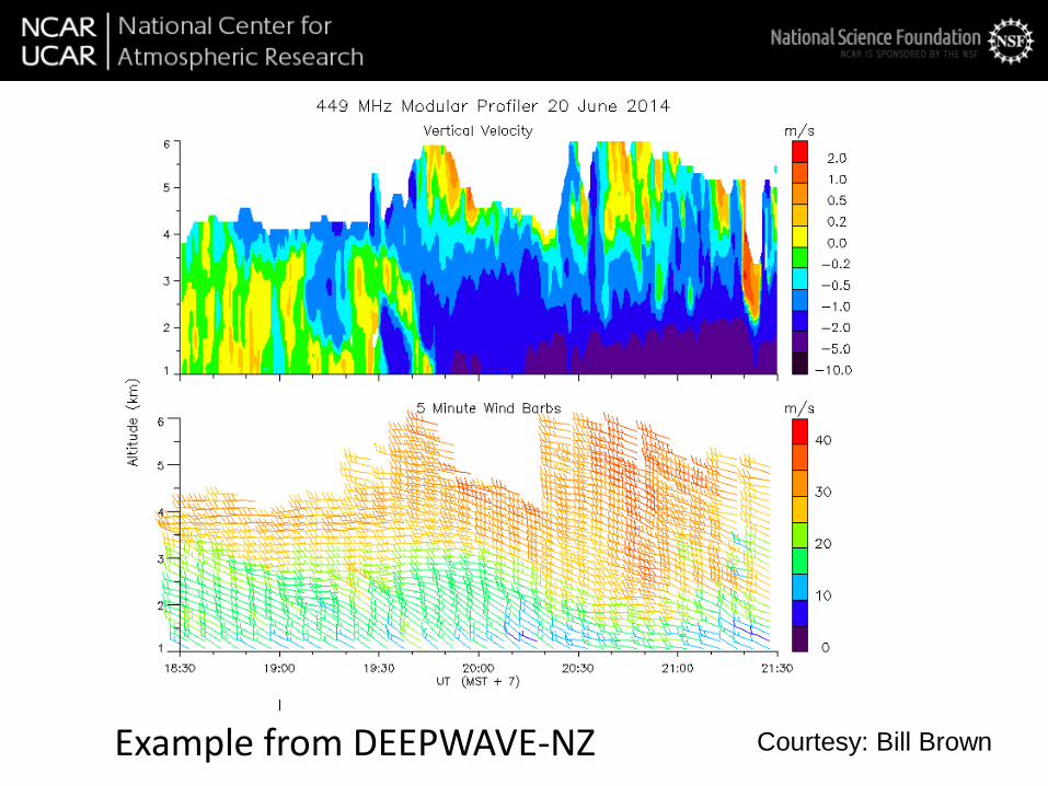
Example from DEEPWAVE-NZ Courtesy: Bill Brown

MMC-2014, 15 – 16 September 2014, Slovenia
Signal processing (in a nutshell)
• P: Backscattered power
• V: Doppler shift
• W: Spectral width
Example: Sampling and processing settings
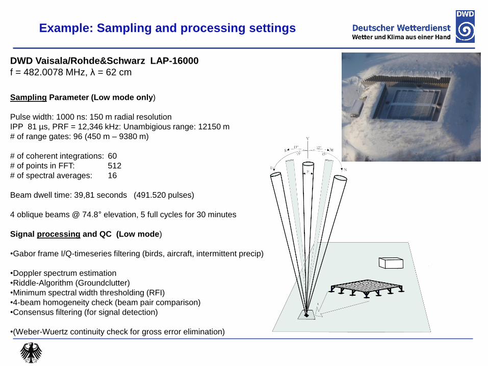
DWD Vaisala/Rohde&Schwarz LAP-16000
f = 482.0078 MHz, λ = 62 cm
Sampling Parameter (Low mode only)
Pulse width: 1000 ns: 150 m radial resolution
IPP 81 µs, PRF = 12,346 kHz: Unambigious range: 12150 m
# of range gates: 96 (450 m – 9380 m)
# of coherent integrations: 60
# of points in FFT: 512
# of spectral averages: 16
Beam dwell time: 39,81 seconds (491.520 pulses)
4 oblique beams @ 74.8° elevation, 5 full cycles for 30 minutes
Signal processing and QC (Low mode)
•Gabor frame I/Q-timeseries filtering (birds, aircraft, intermittent precip)
•Doppler spectrum estimation
•Riddle-Algorithm (Groundclutter)
•Minimum spectral width thresholding (RFI)
•4-beam homogeneity check (beam pair comparison)
•Consensus filtering (for signal detection)
•(Weber-Wuertz continuity check for gross error elimination)
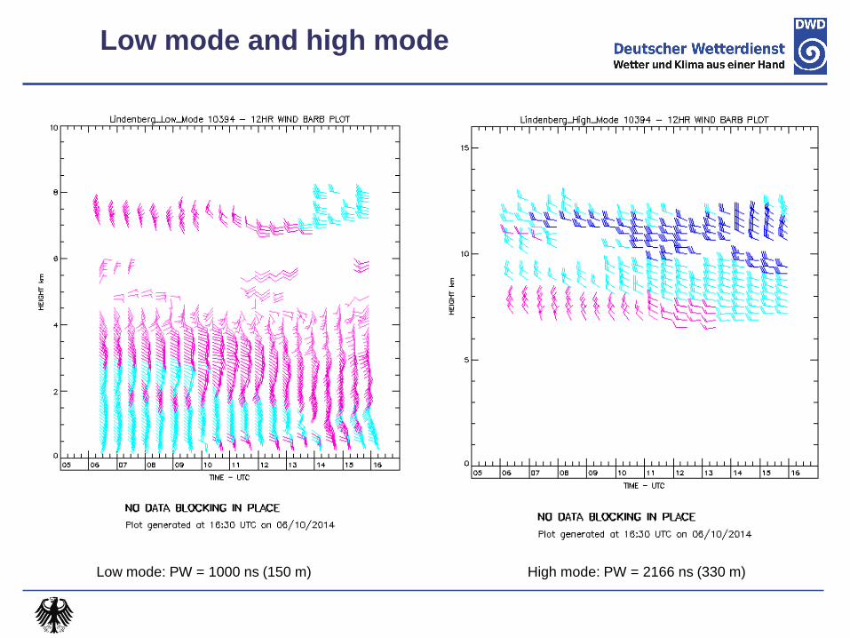
Low mode and high mode
Low mode: PW = 1000 ns (150 m) High mode: PW = 2166 ns (330 m)
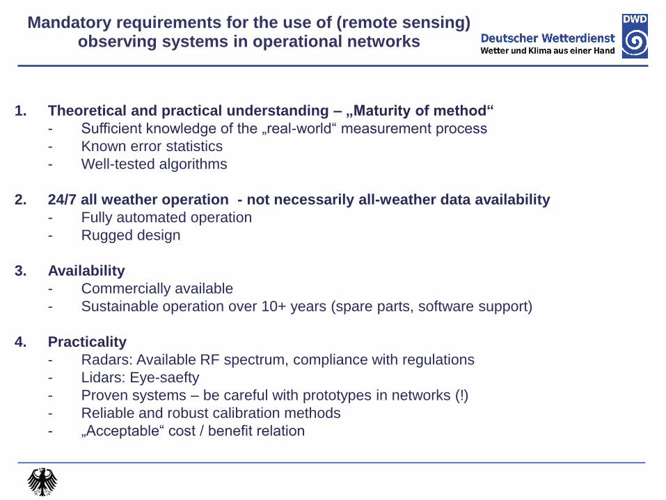
Mandatory requirements for the use of (remote sensing) observing systems in operational networks
1. Theoretical and practical understanding – „Maturity of method“
- Sufficient knowledge of the „real-world“ measurement process
- Known error statistics
- Well-tested algorithms
2. 24/7 all weather operation - not necessarily all-weather data availability
- Fully automated operation
- Rugged design
3. Availability
- Commercially available
- Sustainable operation over 10+ years (spare parts, software support)
4. Practicality
- Radars: Available RF spectrum, compliance with regulations
- Lidars: Eye-saefty
- Proven systems – be careful with prototypes in networks (!)
- Reliable and robust calibration methods
- „Acceptable“ cost / benefit relation
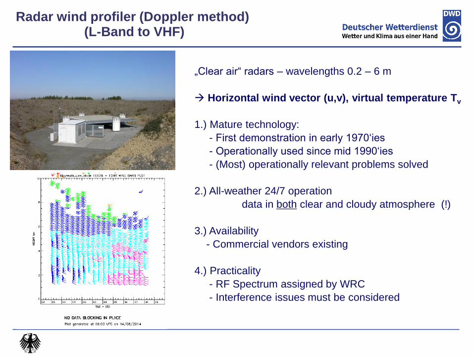
„Clear air“ radars – wavelengths 0.2 – 6 m
Horizontal wind vector (u,v), virtual temperature Tv
1.) Mature technology:
- First demonstration in early 1970‘ies
- Operationally used since mid 1990‘ies
- (Most) operationally relevant problems solved
2.) All-weather 24/7 operation
data in both clear and cloudy atmosphere (!)
3.) Availability
- Commercial vendors existing
4.) Practicality
- RF Spectrum assigned by WRC
- Interference issues must be considered
Radar wind profiler (Doppler method) (L-Band to VHF)
1.RWP networks and data impact in NWP
2.RWP – some fundamentals
3.Accuracy assessment and possibilities for
standardisation
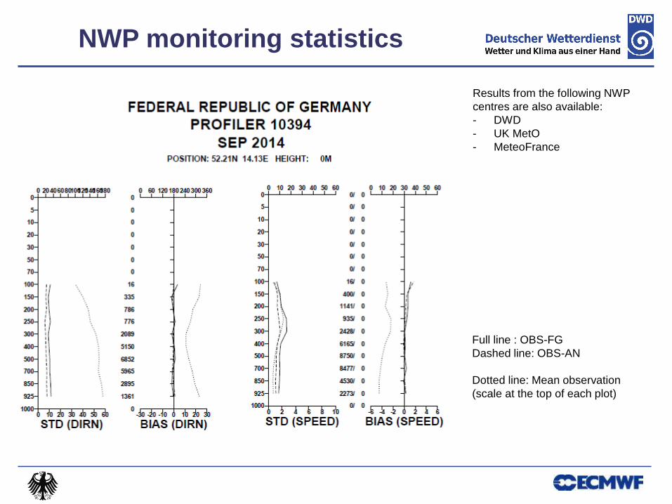
NWP monitoring statistics
Full line : OBS-FG
Dashed line: OBS-AN
Dotted line: Mean observation
(scale at the top of each plot)
Results from the following NWP
centres are also available:
- DWD
- UK MetO
- MeteoFrance

Lidar wind profiler (IR)
Radial wind data from a 24 beam VAD-scan, Oct 03, 2012 08:20 -09:20 UTC
Horizontal wind vector (u,v)
1.) Maturity:
- First demonstration in mid 1960‘ies (CO2 laser)
- Wind shear warning systems since mid 2000
- Testing in operational setting under way
2.) All-weather 24/7 operation: Yes, limited availability
- in and above optically thick clouds
- in particle-free atmosphere (no targets)
3.) Availability
- Commercial vendors existing
- Market currently very active (mainly wind energy)
4.) Practicality
- Easy to deploy, fully autonomous operation
- All-fiber optics: Mechanically very stable
- Eye safe (Laser class 1M)
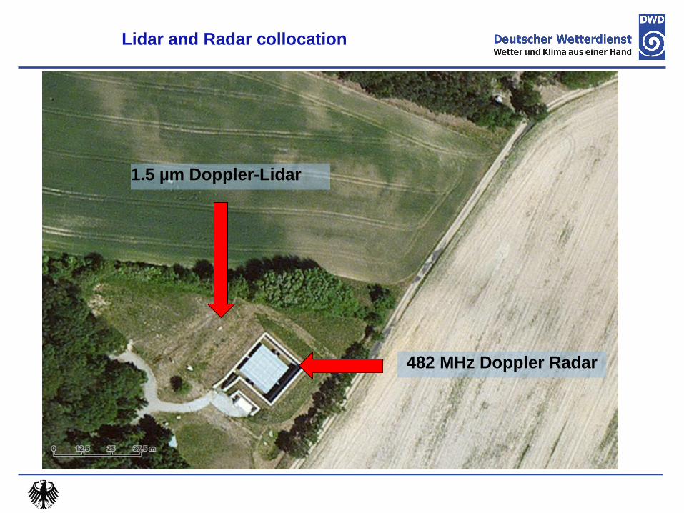
Lidar and Radar collocation
482 MHz Doppler Radar
1.5 µm Doppler-Lidar

Data availability: Radar vs. Lidar wind profiler
(quality controlled data only)
482 MHz RWP, 1 µs pulse, “Low mode”
1. 5 µm Lidar, 160 ns pulse
Oct. 02, 2012 – Oct. 02, 2013 max # : 17568

Comparison statistics: Mean profiles
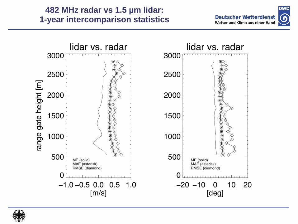
482 MHz radar vs 1.5 µm lidar: 1-year intercomparison statistics
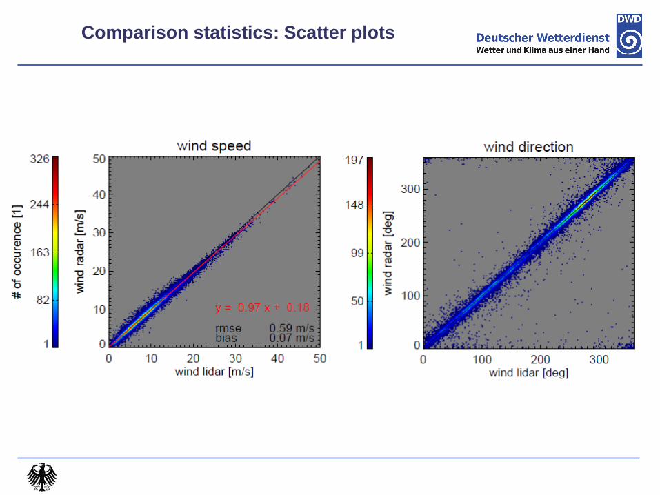
Comparison statistics: Scatter plots
MMC-2014, 15 – 16 September 2014, Slovenia
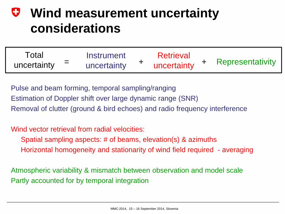
Wind measurement uncertainty
considerations
Total
uncertainty Instrument
uncertainty
Retrieval
uncertainty Representativity = + +
Pulse and beam forming, temporal sampling/ranging
Estimation of Doppler shift over large dynamic range (SNR)
Removal of clutter (ground & bird echoes) and radio frequency interference
Wind vector retrieval from radial velocities:
Spatial sampling aspects: # of beams, elevation(s) & azimuths
Horizontal homogeneity and stationarity of wind field required - averaging
Atmospheric variability & mismatch between observation and model scale
Partly accounted for by temporal integration
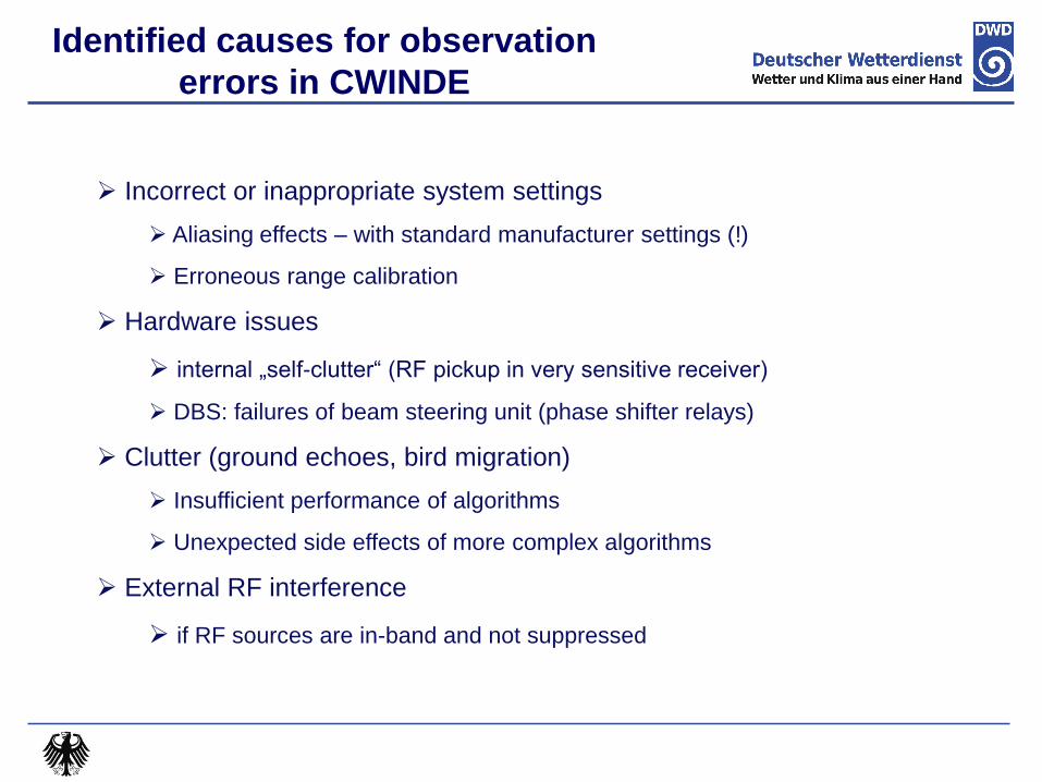
Incorrect or inappropriate system settings
Aliasing effects – with standard manufacturer settings (!)
Erroneous range calibration
Hardware issues
internal „self-clutter“ (RF pickup in very sensitive receiver)
DBS: failures of beam steering unit (phase shifter relays)
Clutter (ground echoes, bird migration)
Insufficient performance of algorithms
Unexpected side effects of more complex algorithms
External RF interference
if RF sources are in-band and not suppressed
Identified causes for observation
errors in CWINDE
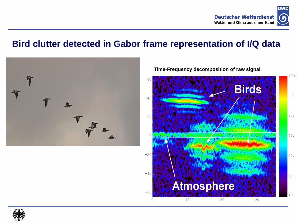
Bird clutter detected in Gabor frame representation of I/Q data
Time-Frequency decomposition of raw signal

Example of external RFI (suppressed by algorithm)
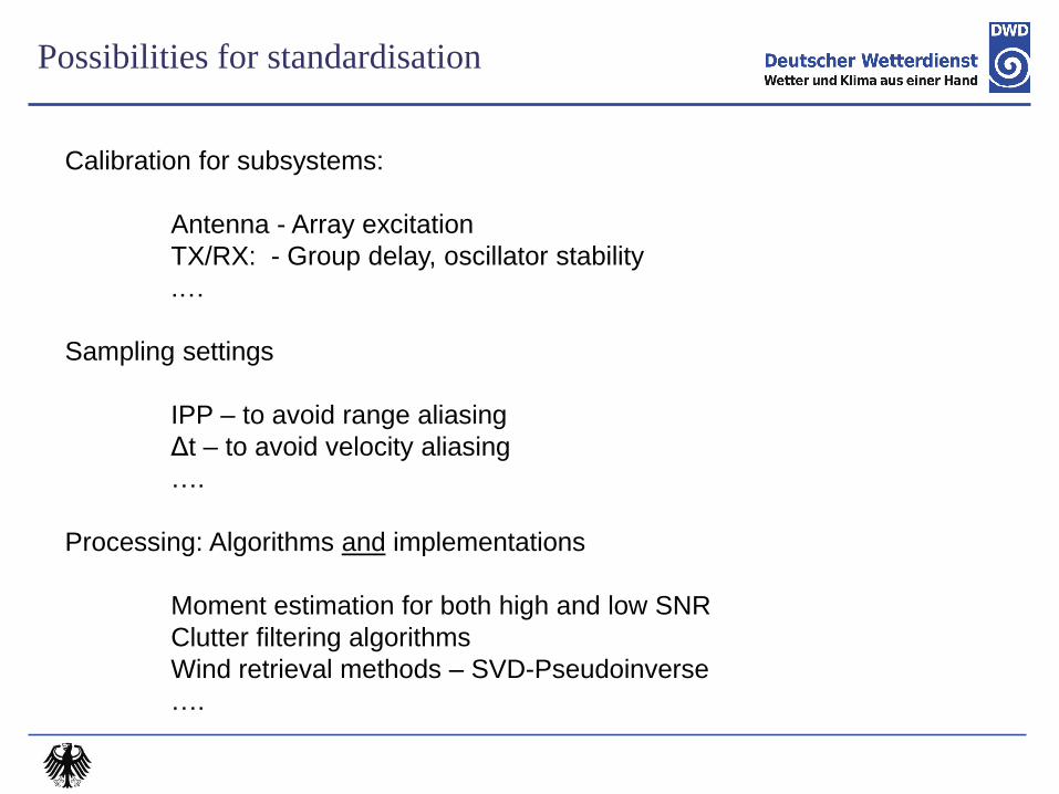
Possibilities for standardisation
Calibration for subsystems:
Antenna - Array excitation
TX/RX: - Group delay, oscillator stability
.…
Sampling settings
IPP – to avoid range aliasing
Δt – to avoid velocity aliasing
….
Processing: Algorithms and implementations
Moment estimation for both high and low SNR
Clutter filtering algorithms
Wind retrieval methods – SVD-Pseudoinverse
….
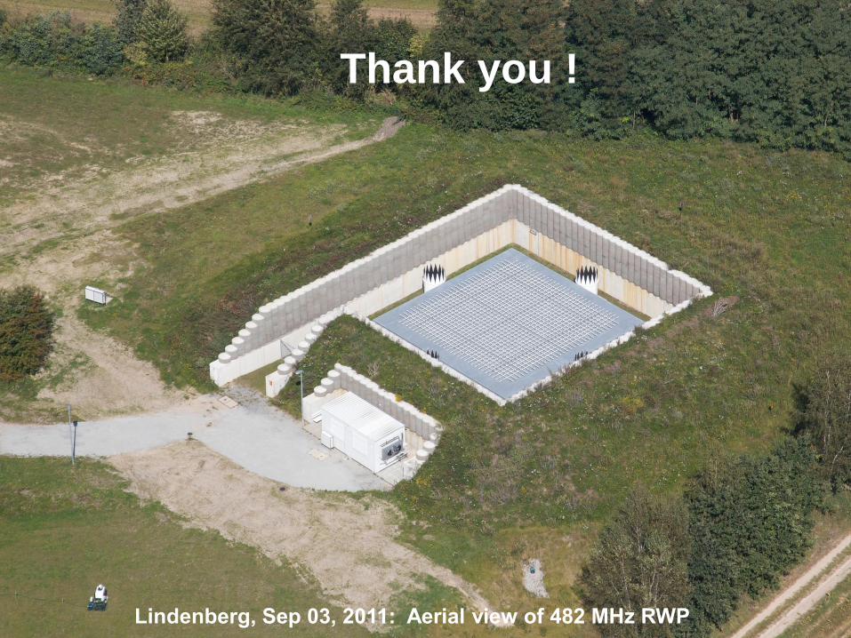
Meteorologisches Observatorium Lindenberg – Richard-Aßmann-Observatorium (2011) Meteorologisches Observatorium Lindenberg – Richard-Aßmann-Observatorium (2011) Meteorologisches Observatorium Lindenberg – Richard-Aßmann-Observatorium (2011) Lindenberg, Sep 03, 2011: Aerial view of 482 MHz RWP
Thank you !

Deutscher
1. Protection of frequencies: Need bands without interfering RF signals
2. Qualified staff crucial – maintain existing knowledge through training and workshops
3. Enforce strict quality control at the sites – “no data is better than bad data” Clutter filtering – many algorithms are existing, bub not always implemented
Detection of non-homogeneous wind field conditions – convection, gravity waves,…
4. Hardware and software maintenance: Radars operate over 10+ years – need for renovation or replacement
Continuous evolution of operating systems – IT security
5. Development and automation of monitoring System failures must be identified quickly
Standardization of RWP “raw data” formats (moments, spectra, I/Q)
NWP monitoring statistics – development of unified graphics (results from different models)
6. Exploit potential of new IR Doppler lidars for Boundary-Layer wind profiling
Implementation of new WMO BUFR template for wind observations in 2015
Challenges for RWP
Deutscher Wetterdienst
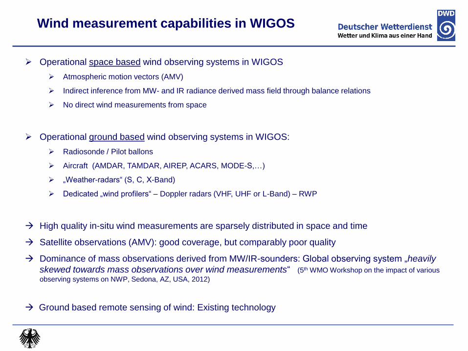
Operational space based wind observing systems in WIGOS
Atmospheric motion vectors (AMV)
Indirect inference from MW- and IR radiance derived mass field through balance relations
No direct wind measurements from space
Operational ground based wind observing systems in WIGOS:
Radiosonde / Pilot ballons
Aircraft (AMDAR, TAMDAR, AIREP, ACARS, MODE-S,…)
„Weather-radars“ (S, C, X-Band)
Dedicated „wind profilers“ – Doppler radars (VHF, UHF or L-Band) – RWP
High quality in-situ wind measurements are sparsely distributed in space and time
Satellite observations (AMV): good coverage, but comparably poor quality
Dominance of mass observations derived from MW/IR-sounders: Global observing system „heavily
skewed towards mass observations over wind measurements“ (5th WMO Workshop on the impact of various
observing systems on NWP, Sedona, AZ, USA, 2012)
Ground based remote sensing of wind: Existing technology
Wind measurement capabilities in WIGOS
FSA
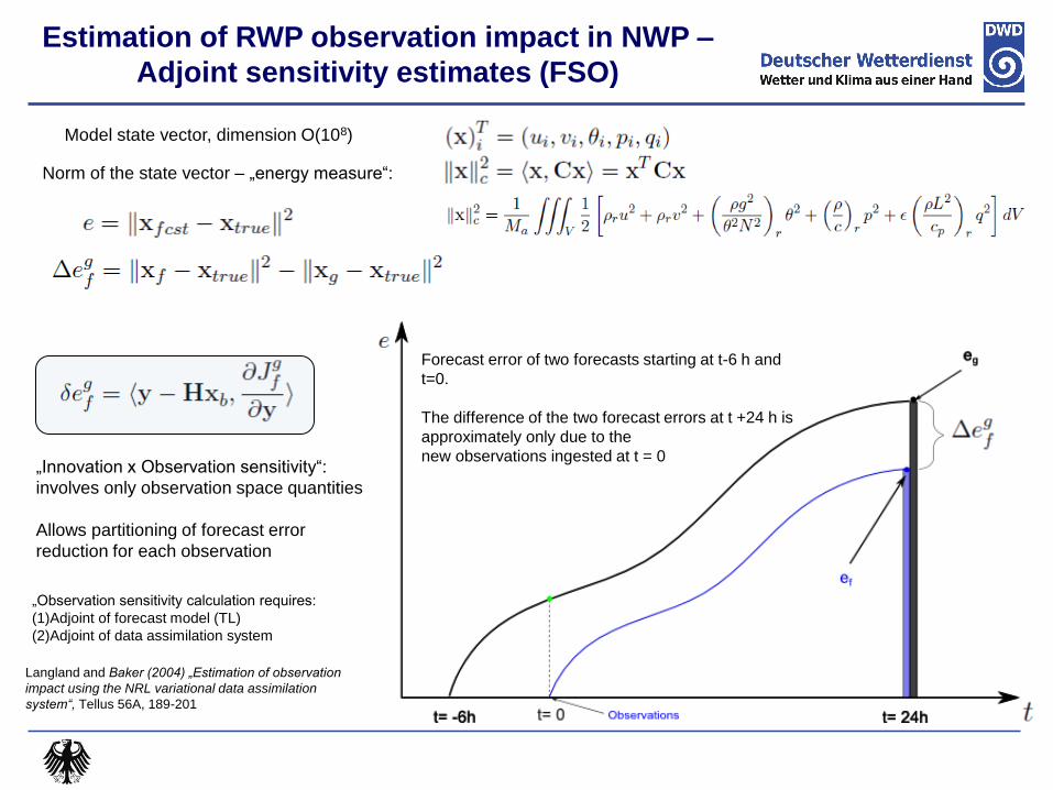
Model state vector, dimension O(108)
Norm of the state vector – „energy measure“:
Forecast error of two forecasts starting at t-6 h and
t=0.
The difference of the two forecast errors at t +24 h is
approximately only due to the
new observations ingested at t = 0
Estimation of RWP observation impact in NWP –
Adjoint sensitivity estimates (FSO)
„Innovation x Observation sensitivity“:
involves only observation space quantities
Allows partitioning of forecast error
reduction for each observation
Langland and Baker (2004) „Estimation of observation
impact using the NRL variational data assimilation
system“, Tellus 56A, 189-201
„Observation sensitivity calculation requires:
(1)Adjoint of forecast model (TL)
(2)Adjoint of data assimilation system
Deutscher Wetterdienst
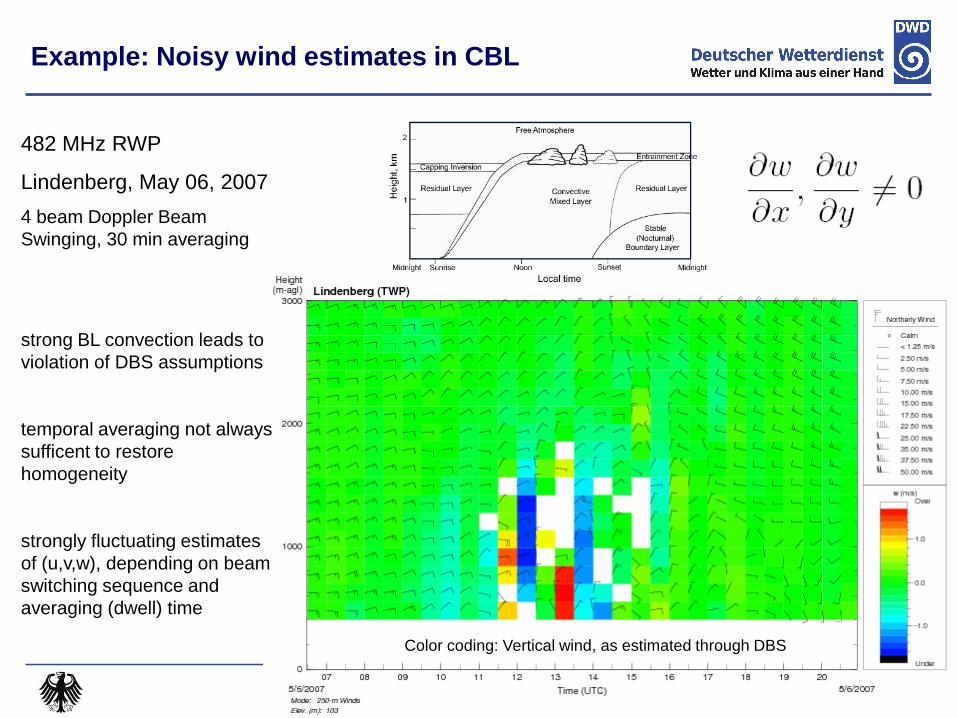
482 MHz RWP
Lindenberg, May 06, 2007
4 beam Doppler Beam
Swinging, 30 min averaging
strong BL convection leads to
violation of DBS assumptions
temporal averaging not always
sufficent to restore
homogeneity
strongly fluctuating estimates
of (u,v,w), depending on beam
switching sequence and
averaging (dwell) time
Example: Noisy wind estimates in CBL
Color coding: Vertical wind, as estimated through DBS
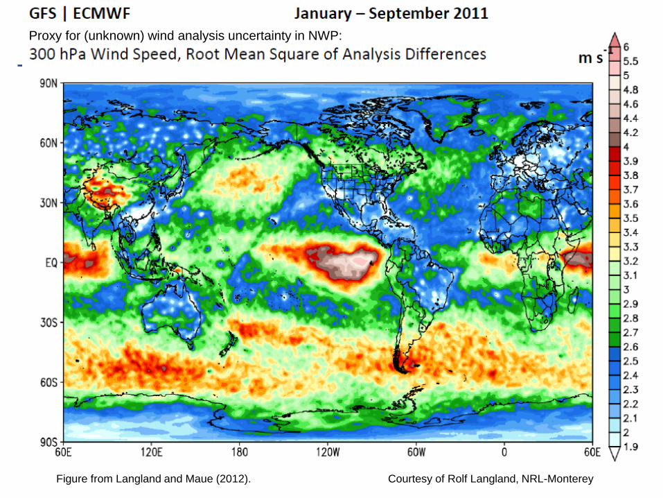
Figure from Langland and Maue (2012). Courtesy of Rolf Langland, NRL-Monterey
Proxy for (unknown) wind analysis uncertainty in NWP:

ADM-Aeolus METOP
Infrared Atmospheric Sounding Interferometer (IASI)
ESA ADM-Aeolus Satellite
ESA‘s Wind-Mission (Demonstrator)
Sun-synchronous orbit, period 90 min
Lidar ALADIN: wavelength 355 nm (UV)
Range-resolved HLOS winds
Launch: Early 2016 (?)
1.) Ground campaigns for A2D
09.10. – 20.10. 2006 Lindenberg
25.06. – 31.07. 2007 Lindenberg
http://www.pa.op.dlr.de/aeolus/
2.) External CAL/VAL after launch
Comparison with RWP data !!