Embed Size (px)
Citation preview

* corresponding author(s) 1
The 4th European sCO2 Conference for Energy Systems
March 23-24, 2021, Online Conference
2021-sCO2.eu-157
OPERATIONAL ANALYSIS OF A SELF-PROPELLING HEAT REMOVAL SYSTEM
USING SUPERCRITICAL CO2 WITH ATHLET
Markus Hofer*
University of Stuttgart
Stuttgart, Germany
Email: [email protected]
stuttgart.de
Michael Buck
University of Stuttgart
Stuttgart, Germany
Jörg Starflinger
University of Stuttgart
Stuttgart, Germany
ABSTRACT
This study proposes preliminary guidelines for the design
and operation of a supercritical carbon-dioxide (sCO21) heat
removal system for nuclear power plants. Based on a
thermodynamic optimization the design point is calculated
incorporating an existing small-scale compressor map. The
behavior of the cycle is tested under varying boundary conditions
on the steam side of the compact heat exchanger. The simulations
are carried out with the thermal-hydraulic system code ATHLET,
which has been extended for the simulation of sCO2 power
cycles. The extensions include the thermodynamic properties,
heat transfer and pressure drop correlations as well as
performance map based turbomachinery models, which take the
real gas behavior of sCO2 into account. During the decay heat
transient, compressor surge occurs in some of the simulated
cases. In order to avoid compressor surge and to follow the decay
heat curve, the compressor speed is reduced together with the
steam temperature. This enables to operate one single system
down to a thermal load of less than 50 % even under the design
restriction caused by the application of the existing compressor
performance map.
INTRODUCTION
In case of a station blackout (SBO) and loss of ultimate heat
sink (LUHS) accident in a boiling water reactor (BWR) or
pressurized water reactor (PWR), the plant accident management
strongly depends on the depends on the recovery of electricity,
e.g. by emergency diesel generators, or from external sources. If
not available, core integrity may be violated, like in Fukushima
Dachii. Such scenarios lead to the development of advanced
1 sCO2 is defined as carbon dioxide at supercritical conditions with
p > 73.8 bar and T > 31 °C
decay heat removal systems. Since space is a limitation in
existing power plants, the supercritical carbon-dioxide (sCO2)
heat removal system “sCO2-HeRo” was proposed [1–3]. This
system can be incorporated in new nuclear power plants as well
as retrofitted to existing nuclear power plants. The system
consists of a compact heat exchanger (CHX), a gas cooler,
serving as the ultimate heat sink (UHS), and the turbomachinery,
one compressor and one turbine mounted on a common shaft
together with a generator. Since the momentum from the turbine
is sufficient to simultaneously drive the compressor and generate
more electricity than used by the fans of the UHS, the system is
self-propelling. The excess electricity can even be used to
support other accident measures, e.g. recharging batteries. sCO2
is selected as a working fluid because of its favorable fluid
properties, enabling the design of a very compact system.
Moreover, sCO2 is not combustible, non-toxic and commercially
available.
Figure 1 shows the scheme of the sCO2-HeRo attached to a
BWR. In the case of an accident the valves, which connect the
compact heat exchanger (CHX) to the main steam line, open
automatically. Driven by natural circulation, the steam
condenses and heats the sCO2 in the CHX. Due to the space
limitations, the CHX consists of many channels with a small
hydraulic diameter, so called mini-channels, in order to reach a
large heat transfer area [1]. The pressurized and heated sCO2 is
expanded in the turbine, which drives the compressor and
generates power for the fans of the gas cooler. After the turbine,
the remaining heat of the sCO2 is removed in the gas cooler to
the ultimate heat sink. Finally, the sCO2 is compressed and flows
to the CHX. Similarly, the sCO2-HeRo can be attached to the
DOI: 10.17185/duepublico/73983

2
secondary loop of a PWR. In the primary loop natural circulation
will develop due to the decay heat input and the heat removal via
the steam generator. Consequently, the sCO2-HeRo can be used
for BWRs as well as PWRs.
Figure 1: The sCO2 heat removal system attached to a BWR [1]
including the different states in the cycle: compressor inlet (1),
compressor outlet (2), turbine inlet (3), turbine outlet (4)
For the simulation of nuclear power plants, different thermal
hydraulic system codes are used, e.g. CATHARE, RELAP,
TRACE and ATHLET [4]. Because sCO2 is also considered as a
working fluid in the power generation cycle of 4th generation
reactor concepts, work is in progress to extend these system
codes for the simulation of sCO2 power cycles [1], [5], [6], [7],
[8]. Venker investigated the feasibility of the sCO2-HeRo
approach for a BWR in detail and implemented first extensions
in ATHLET for the simulation of the heat removal system. First
simulations showed that the grace period can be extended to
more than 72 h [1]. The grace period is the period of time for
which the nuclear power plant remains in a safe condition
without the need of human interaction [9]. In the frame of the
sCO2-HeRo-project further reports and studies were published,
e.g. dealing with the start-up of the system or the design and
control [2,10–12]. In the frame of the project, Hecker and
Seewald [10] analysed the decay heat removal from a BWR with
a nuclear power plant simulator. This analysis suggested that
manual actions by operators and a higher heat removal capacity
than proposed by Venker would be necessary to avoid automatic
depressurisation at low level in the reactor vessel. Because a
comparable level drop on the secondary side of a steam generator
does not initiate automatic depressurization from the reactor
protection system, more operational flexibility can be expected
for a PWR. Hajek et al. describe the basic principles for the
integration of the sCO2-HeRo into the European PWR fleet
including safety, reliability and thermodynamic design
considerations [11,12]. Hofer et al. carried out preliminary
design calculations and provided considerations for the operation
of the Brayton cycle, e.g. it may be beneficial to locate the design
point of the turbomachinery in part load and the system may be
operated via a shaft speed control [13].
In general, the analysis of the sCO2-HeRo approach can be
conducted considering different time intervals and levels of
complexity. In terms of time, the accident can be divided into the
first phase, where the decay heat exceeds the heat removal
capacity of the system, and the second phase, where the heat
removal capacity is higher. Regarding complexity, different parts
of the system or the whole system can be analyzed. This paper
focusses on the sCO2 cycle including the steam side of the CHX
and on the second phase regarding time. Compared to previous
publications, the sCO2 cycle is modelled and analyzed in more
detail. In the theoretical section, this paper shortly presents
design and operational considerations for the sCO2-HeRo
system and the extensions of the thermal-hydraulic system code
ATHLET (Analysis of THermal-hydraulics of LEaks and
Transients). In the results section, the system design is provided
using the scaled performance map of the compressor designed in
the sCO2-HeRo project [8,14]. Afterwards, the system is
simulated in ATHLET considering and comparing different
control strategies.
THEORY
Cycle design and operation
In case of an accident, the main purpose of the sCO2-HeRo
system is to remove the decay heat reliably over several days.
Due to the exponential decrease of the decay heat and due to
changing ambient conditions, the system must be able to operate
over a wide range of conditions. From a thermodynamic point of
view, the worst condition for the system occurs at the highest
ambient temperature and the smallest decay heat input per
system, which is considered. Consequently, it might be a valid
approach to start the system design from this point. However, the
lowest ambient temperatures must also be taken into account,
because if no operational action is undertaken the compressor
inlet temperature will decrease with the ambient temperature.
This leads to an increasing compressor inlet density and
potentially drives the compressor to surge. To avoid approaching
the surge line, one option is to keep the compressor inlet
temperature sufficiently high. This can be achieved by
decreasing the fan speed in order to decrease the performance of
the gas cooler. However, it must be checked if this measure is
sufficient for the lowest ambient temperatures because heat
transfer occurs also with the fans switched off. An additional
measure is to design a modularized gas cooler which enables
decoupling of certain sections or to increase the compressor mass
flow rate via a bypass. Ambient temperature variations and
extremely low ambient temperatures are not in the scope of this
paper and will be analyzed in the future. This paper analyses the
operation of the system at the highest ambient temperature,
which is assumed to be 45 °C, with the naturally declining decay
heat as boundary condition.
The next step to the system design is to define the maximum
thermal power, which must be removed reliably by the system.
Venker has shown that it is not necessary to design the system
for the maximum decay heat occurring directly after the reactor
scram [1]. Depending on the power plant type (BWR or PWR),
the time delay allowed to start the system along with additional
supporting systems, as well as the required system capacity
differ. As a first step, the required system size can be determined
1
2
3
4

3
with a simple heat balance or obtained by means of reactor
simulations where the system is represented by a heat sink. As
long as the decay power exceeds the thermal power of the
system, steam is blown off to keep the pressure below a certain
threshold. Since, it is assumed that the water inventory cannot be
replaced, the water level must be kept high enough to enable the
operation of the sCO2-HeRo as well as to ensure the cooling of
the reactor core. Former analysis demonstrated that more than
one system is needed to follow the declining decay heat curve
[1]. In this paper, a system size of 10 MW is selected, which
enables the use of this system for different reactor types and
sizes, because just the number of systems has to be adapted. A
simple heat balance suggested that 60 MW might be sufficient
for a PWR with a thermal power of 3840 MW. Comparing the
total power of the sCO2-HeRo system to the decay heat curve
suggests a power break even after 3000 s. Thus, the system
operates at its maximum power from start-up to 3000 s and then
the system has to adapt to the declining decay heat, shown in
Figure 2. According to the User Manual of ATHLET ANS
Standard ANS‐5.1‐1979 is used [15] and the same curve as in the
analysis of Venker is applied, which is the decay heat occurring
after 300 days of operation [1]. After the power break even,
removing more power from the reactor than is produced by the
decay heat will cause a cool down of the reactor. This results also
in a lower temperature difference being available for the sCO2-
HeRo and eventually will stop the operation of the system
because the power balance becomes negative as will be shown
in the results section. Venker already demonstrated the need for
a balance between heat generation and heat removal in order to
obtain a stable operation of the sCO2-cycle attached to a BWR
[1]. Since the decay heat is decreasing continuously, it might be
necessary to control the system in part load. The required part
load capability of the system also depends on the number of
systems installed and the control strategy. Future analysis will
consider these aspects in more detail. However, the general
procedure and the conclusion presented in this paper will still
stay valid because this analysis is not dependent on the system
size or the time of power break even.
Figure 2: Decay power [1,10,15] divided by the thermal power
of the reactor over time
After these general considerations the thermodynamic
design of the system will be discussed in more detail. As
mentioned before, the worst operation point of the system is the
lowest power input per system at the highest ambient
temperature. At this point, the turbomachinery efficiencies must
be high enough to guarantee a self-propelling operation. This
should be considered in future designs using an integrated design
approach, which iteratively adapts the cycle and turbomachinery
design. In this paper, the design will be carried out at the
maximum power input per system with an existing compressor
performance map. The heat exchangers should also be designed
for this point because they are required to remove the design
power. The thermodynamic cycle design can be conducted using
a simple thermodynamic optimization [13] using the basic
thermodynamic relations for and between the components also
involving the isentropic efficiencies of the compressor and the
turbine [16]. The optimization maximizes the specific power
output of the system and not the efficiency because the system
shall be self-propelling as long as possible and the system
efficiency is of no interest. For given compressor inlet
temperature 𝜗1, turbine inlet temperature 𝜗3, turbomachinery
efficiencies 𝜂𝑐 and 𝜂𝑡, pressure drops in the heat exchangers
Δ𝑝𝑈𝐻𝑆 and Δ𝑝𝐶𝐻𝑋 and the relative power consumption of the fans
𝑘𝑓𝑎𝑛, the compressor inlet and outlet pressure 𝑝1 and 𝑝2 are
optimized to maximize the specific power output of the system
∆𝑤 = 𝑓(𝑝1, 𝑝2, 𝜗1, 𝜗3, 𝜂𝑐, 𝜂𝑡 , 𝑘𝑓𝑎𝑛 , Δ𝑝𝑈𝐻𝑆 , Δ𝑝𝐶𝐻𝑋). (1)
For the thermodynamic design point optimization, the piping
pressure drop is neglected and the power of the fans is assumed
to be a linear function of the heat removal capacity. The excess
power of the cycle ∆𝑃 is calculated by multiplying ∆𝑤 with the
mass flow rate of the cycle.
Simulation of the Brayton cycle
The code extensions of ATHLET described in the following
can be found in more detail in publications of Venker [1] and
Hofer et al. [8,17]. In the supercritical region, the
thermodynamic properties of CO2 are calculated with fast
splines, which were derived from the equation of state [18]. In
ATHLET, the heat transfer coefficient of CO2 is calculated with
the Gnielinski correlation [19]. The pressure drop of supercritical
CO2 is derived from the Colebrook equation, which is
recommended for normal pipes as well as for mini-channels [20].
Additionally, form loss coefficients can be applied, to e.g. model
the inlet and outlet plenum of the CHX. For water the
implemented correlations [21] are used except for the film
condensation, where the ATHLET correlations were improved
[17] and now the correlations given in [22,23] are used. For
turbine and compressor, different models are available. In this
paper, Stodolas cone law [24] and an efficiency correlation for
radial turbines [25] is used for the turbine. The compressor is
simulated with a performance map approach [8,26]. The
performance map generated from experimental data or CFD
simulations is transposed to a dimensionless map, shown in
Figure 3.

4
Figure 3: Dimensionless isentropic enthalpy difference 𝛥ℎ𝑖𝑠∗ as
a function of the axial and tangential Mach Numbers (𝑀𝑎𝑎 and
𝑀𝑎𝜃)
The x- and y-axis are the axial and tangential Mach
numbers, given by
𝑀𝑎𝑎 =�̇�
𝜌𝑐𝐷2 (2)
𝑀𝑎𝜃 =𝑁𝐷
𝑐, (3)
where 𝑁 is the rotational speed, 𝐷 the impeller diameter and 𝑐
the speed of sound. All thermodynamic parameters are
determined for the inlet condition. As main difference to other
performance map approaches, the speed of sound is calculated
via the equation of state and not using ideal gas assumptions. On
the z-axis the dimensionless isentropic enthalpy difference 𝛥ℎ𝑖𝑠∗
or the corrected pressure ratio 𝜋𝑐 and the efficiency 𝜂 can be
presented. The equation for the dimensionless isentropic
enthalpy difference is
𝛥ℎ𝑖𝑠∗ =
𝛥ℎ𝑖𝑠
𝑐2 . (4)
RESULTS AND DISCUSSION
Cycle design
As mentioned in the theory section, the cycle design is
carried out for the maximum heat load, which is 10 MW per unit,
at an ambient temperature of 45 °C. The boundary conditions for
the design calculation are summarized in Table 1. With the pinch
point temperature differences, the compressor and turbine inlet
temperature can be calculated. Then the optimal design point can
be found according to the procedure described in the theory
section. However, for the simulation of the compressor an
existing performance map of small-scale compressor [14] shall
be scaled-up and used. This is carried out using equations 2, 3
and 4 and, but conservatively, without any additionally
efficiency correction. Therefore, the efficiency of the large-scale
compressor is equal to the efficiency of the given small-scale
compressor. The pressure ratio and the outlet state can be
determined with the inlet state and the performance map using
equation 4. Since, the condition at the compressor inlet is also
given by the thermodynamic optimization, the compressor outlet
condition is defined by the underlying performance map. Thus,
the optimization of 𝑝1 and 𝑝2 reduces to an optimization of only
𝑝1 with 𝑝2 given by the compressor characteristic.
Table 1: Boundary conditions for the design process
Parameter Unit Value
�̇�𝑪𝑯𝑿 MW 10
𝚫𝑻𝑷𝑷,𝑪𝑯𝑿 K 10
𝚫𝑻𝑷𝑷,𝑼𝑯𝑺 K 5
𝚫𝑻𝒔𝒖𝒃,𝑯𝟐𝑶 K 8
𝚫𝒑𝑪𝑯𝑿 bar 2
𝚫𝒑𝑼𝑯𝑺 bar 0.25
𝝑𝒊𝒏,𝑯𝟐𝑶 °C 296
𝒉𝒊𝒏,𝑯𝟐𝑶 kJ/kg 2760
𝜼𝒄 - 0.72
𝜼𝒕 - 0.8
𝒌𝒇𝒂𝒏 kWel / MWth 8.5
The thermodynamic design parameters from the
optimization process are summarized in Table 2. Compared to
conventional sCO2 cycles, the design point is located quite far
above the critical point with a compressor inlet state of 50 °C and
12 MPa. The high compressor inlet pressure results from the high
design point ambient temperature of the system.
Table 2: Optimal thermodynamic design point with the
restriction of the existing compressor performance map
𝝑 in °C 𝒑 in MPa
Compressor Inlet (1) 50 12
Compressor Outlet (2) 69 18.8
Turbine Inlet (3) 286 18.7
Turbine Outlet (4) 246 12
In Figure 4, the power output for the optimized design
conditions is shown varying the turbine inlet temperature and the
pressure ratio. The actual design point is located at the maximum
temperature and at a pressure ratio of 1.57. On the contrary, the
theoretical optimal design point is also located at the maximum
temperature and at a pressure ratio of 3.09. The power output of
the system at these two points is 440 kW and 807 kW,

5
respectively. Due to the application of an existing small-scale
compressor map, the thermodynamic design point deviates from
the optimal design point in terms of pressure ratio. The efficiency
of the system with 4.4 % is quite small. However, as mentioned
before, the only task of the system is to remove the decay heat
reliably and not to generate power, therefore, the efficiency is of
no interest. The lower pressure ratio of the actual design might
result in a worse performance in the transient calculation because
e.g. reducing the shaft speed decreases the pressure ratio further.
However, the main focus here is to present the procedure and to
enable an off-design simulation of the system and not to give
quantitative results for the best system design. Additionally, it
might be sufficient to choose a compressor with a pressure ratio
smaller than the optimum value, which might reduce the system
cost keeping in mind that the pressure ratio of a single stage
compressor is technically limited to approximately 2.0. The
compressor speed and the impeller diameter of the large-scale
compressor can be determined using equations 2 and 3. Since,
the design point Mach numbers of the small-scale machine are
the same for the large-scale machine and the compressor inlet
condition is given by the thermodynamic optimization, it is
possible to solve the two equations for the two unknowns. This
results in a compressor impeller diameter of 0.22 m and a
rotational speed of 12700 1/min.
Figure 4: Maximized power output ∆𝑃 as a function of pressure
ratio 𝑝2/𝑝1 and turbine inlet temperature 𝜗3 for the given design
boundary conditions
The geometry of the CHX plates follows [16,17]. The
channel length and number are adapted to reach the desired
temperatures and transferred power. The steam is assumed to
enter the CHX saturated and to leave slightly subcooled. For the
2x1 mm rectangular channels, this results in 11070 channels with
a length of 0.85 m. They can be arranged into 90 plates with 123
channels each, leading to a size of approximately 0.9 m x 0.4 m
x 0.2 m. For the UHS an existing design [27] was scaled down
leading to 190 pipes with a length of 15 m. For simplicity the
design only covers the sCO2-side. The pipe length between the
components and the diameter is assumed to 22.5 m and 0.2 m,
respectively [12]. The whole design is valid for a cycle attached
to a PWR. In case of a BWR the steam temperature could be
slightly lower due to the lower blow-off pressure. This can be
compensated by slightly modifying the whole design or by just
adapting the CHX to reach a lower pinch point temperature
difference.
Simulation of the Brayton cycle
In this section, the simulated system, the boundary
conditions and the simulation results for the sCO2-HeRo cycle
are shown and operational conclusions are drawn. Assuming that
in the first phase of the accident the heat removal system operates
at its maximum capacity of 10 MW per unit, the transient
analysis is started at 3000 s when the decay power is equal to the
system capacity. As mentioned before, the ambient temperature
is set to 45 °C. However, this is not modelled explicitly, because
no design of the air-side of the UHS is available. Instead, it is
assumed that the cooling power �̇�𝑈𝐻𝑆 can be controlled via the
fan speed to reach the desired temperature difference between
the compressor inlet temperature Δ𝑇𝑃𝑃,𝑈𝐻𝑆 and the ambient
temperature. This assumption should be valid because the decay
power is declining slowly after 3000 s. Since the nuclear power
plant is not simulated, boundary conditions for the steam must
be provided. The conditions at the start are given by the design
with saturated steam at 296 °C at the inlet and slightly subcooled
water at 288 °C at the outlet of the CHX. From a power balance,
the steam mass flow rate can be determined, which is 7 kg/s at
the design point of the system. The initial conditions are the same
for all cases. During the transient, the enthalpy at the inlet of the
CHX are always kept at the saturation point of steam for the
given temperature. Therefore, the pressure at the inlet is also the
saturation pressure. To provide an overview of the boundary
conditions, they are summarized in Table 3 and the case specific
boundary conditions will be explained in detail at the beginning
of each case.
Table 3: Boundary conditions of analyzed cases
Case 1 Case 2 Case 3a Case 3b Case 4
�̇�𝑯𝟐𝑶 declining constant declining declining calculated
𝒉𝒊𝒏,𝑯𝟐𝑶 at saturation point of steam (𝑥=1) for all cases
𝝑𝒊𝒏,𝑯𝟐𝑶 constant declining constant constant declining
𝚫𝑻𝒔𝒖𝒃,𝑯𝟐𝑶 not constant (result) constant at design value
𝚫𝑻𝑷𝑷,𝑼𝑯𝑺 constant at design value except for 3b (increasing)
𝑵 constant at design
value controlled to match Δ𝑇𝑠𝑢𝑏,𝐻2𝑂
�̇�𝑼𝑯𝑺 controlled to match Δ𝑇𝑃𝑃,𝑈𝐻𝑆
�̇�𝑪𝑯𝑿 /
�̇�𝒅𝒆𝒄𝒂𝒚
(result)
>1 ≈1 1
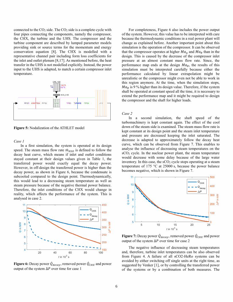
The nodalization of the ATHLET model is shown in Figure
5. The H2O side consists of an inlet, an outlet and the CHX
channels. The enthalpy is specified at the inlet and the pressure
at the outlet. Through a heat conduction object the H2O side is
6
connected to the CO2 side. The CO2 side is a complete cycle with
four pipes connecting the components, namely the compressor,
the CHX, the turbine and the UHS. The compressor and the
turbine component are described by lumped parameter models
providing sink or source terms for the momentum and energy
conservation equation [8]. The CHX is modelled with a
representative channel pair including form loss coefficients for
the inlet and outlet plenum [8,17]. As mentioned before, the heat
transfer in the UHS is not modelled explicitly. Instead, the power
input to the UHS is adapted, to match a certain compressor inlet
temperature.
Figure 5: Nodalization of the ATHLET model
Case 1
In a first simulation, the system is operated at its design
speed. The steam mass flow rate �̇�𝐻2𝑂 is defined to follow the
decay heat curve, which means if inlet and outlet conditions
stayed constant at their design values given in Table 1, the
transferred power would exactly equal the decay power.
However, in off-design the transferred power is higher than the
decay power, as shown in Figure 6, because the condensate is
subcooled compared to the design point. Thermodynamically,
this would lead to a decreasing steam temperature as well as
steam pressure because of the negative thermal power balance.
Therefore, the inlet conditions of the CHX would change in
reality, which affects the performance of the system. This is
analysed in case 2.
Figure 6: Decay power �̇�𝑑𝑒𝑐𝑎𝑦, removed power �̇�𝐶𝐻𝑋 and power
output of the system ∆𝑃 over time for case 1
For completeness, Figure 6 also includes the power output
of the system. However, this value has to be interpreted with care
because the thermodynamic conditions in a real power plant will
change as explained before. Another important point about this
simulation is the operation of the compressor. It can be observed
that the compressor operates at higher 𝑀𝑎𝑎 and 𝑀𝑎𝜃 than in the
design. This is caused by the decrease of the compressor inlet
pressure at an almost constant mass flow rate. Since, the
performance map ends at the design 𝑀𝑎𝜃, the results of this
simulation must be interpreted carefully because either the
performance calculated by linear extrapolation might be
unrealistic or the compressor might even not be able to work in
this region anymore. At the time, when the simulation stops,
𝑀𝑎𝜃 is 9 % higher than its design value. Therefore, if the system
shall be operated at constant speed all the time, it is necessary to
extend the performance map and it might be required to design
the compressor and the shaft for higher loads.
Case 2
In a second simulation, the shaft speed of the
turbomachinery is kept constant again. The effect of the cool
down of the steam side is examined. The steam mass flow rate is
kept constant at its design point and the steam inlet temperature
and pressure are decreased keeping the inlet saturated. The
decrease is adapted to approximately follow the decay heat
curve, which can be observed from Figure 7. This enables to
analyse the influence of decreasing steam temperatures on the
sCO2 cycle. In the nuclear power plant, the steam temperature
would decrease with some delay because of the large water
inventory. In this case, the sCO2 cycle stops operating at a steam
temperature of 175 °C at 25000 s, because the power balance
becomes negative, which is shown in Figure 7.
Figure 7: Decay power �̇�𝑑𝑒𝑐𝑎𝑦, removed power �̇�𝐶𝐻𝑋 and power
output of the system ∆𝑃 over time for case 2
The negative influence of decreasing steam temperatures
and, therefore, turbine inlet temperatures can be also observed
from Figure 4. A failure of all sCO2-HeRo systems can be
avoided by either switching off single units at the right time, as
suggested by Venker [1], or by controlling the transferred power
of the systems or by a combination of both measures. The

7
disadvantage of just switching off single units at a certain time is
that the right time for the shutdown needs to be determined.
Another option would be to follow the decay heat curve by
controlling the sCO2 cycle. This will be analysed in the next case.
Like in the previous case, it has to be noted that the
compressor operates at higher 𝑀𝑎𝑎 and 𝑀𝑎𝜃 than in the design.
This is due to the same reasons as in case 1. At the time, when
the simulation stops, 𝑀𝑎𝜃 is 14 % higher than its design value.
In this case, the effect is stronger because the compressor inlet
pressure decreases further.
Case 3
In the third simulation, the boundary conditions of the first
simulation are applied and, additionally, the shaft speed of the
turbomachinery is controlled in order to keep the sub-cooling
Δ𝑇𝑠𝑢𝑏,𝐻2𝑂 at the water outlet constant. Thus, all thermodynamic
conditions of the water-side remain constant, only the mass flow
rate varies according to the decay heat. Therefore, the removed
heat exactly equals the decay heat. At the beginning, this method
works well, but after 20000 s the system stops because of
compressor surge. The operation line of the compressor is shown
in Figure 8 together with the numerical surge line. The current
case is labelled “3a”. The numerical surge line is located where
𝛥ℎ𝑖𝑠∗ reaches its maximum with changing 𝑀𝑎𝑎. To the right of
the surge line is the stable operation range, to the left of it the
unstable range. The other simulations also included in this figure
are presented in the following sections. Additionally, the cycle
mass flow rate over time is displayed in Figure 8 to indicate the
stop of the system and support the following discussion.
When the compressor crosses the surge line in the
simulation, the simulation becomes unstable and stops. In order
to avoid compressor surge, the decrease of the axial Mach
number 𝑀𝑎𝑎 must be limited. According to equation 2, this can
be achieved by reducing the density and the speed of sound at
the compressor inlet (measure 1) or by limiting the mass flow
rate decrease compared to the current simulation (measure 2).
Measure 2 can be enforced by decreasing the steam temperature,
as explained later together with case 4, or with a compressor
recirculation line or a turbine bypass. In this paper, only the basic
layout without additional bypasses is considered to keep the heat
removal system as simple as possible. Furthermore, since no
inventory control system has been considered, measure 1 can
only be achieved by increasing the compressor inlet temperature
𝜗1 (measure 1.1) or by decreasing the inlet pressure 𝑝1 (measure
1.2). An increase of 𝜗1 can be achieved by also increasing the
temperature difference between the ambient air and the
compressor inlet Δ𝑇𝑃𝑃,𝑈𝐻𝑆. This action corresponds to a decrease
of the fan speed.
In simulation 3b, this measure is tested by applying all
boundary conditions of simulation 3a except for Δ𝑇𝑃𝑃,𝑈𝐻𝑆, which
is increased steadily during the simulation. From Figure 8, it can
be observed that the compressor surge is postponed but still
occurs after 45000 s. At this time, 𝜗1 is already increased by 13
K and the power output of the system almost decreased to zero.
Thus, the increase of 𝜗1 also leads to a lower power output of the
system. Consequently, the system will stop due to either
compressor surge or a negative power balance. The occurring
compressor surge is mainly due to the decrease of the mass flow
rate, which is similar to simulation 3a. Therefore, measure 1.1 is
not sufficient without taking into account measure 2.
Furthermore, measure 1.1 should be avoided due to the negative
impact on the power output, as explained above.
Case 4
In order to define the boundary conditions for the next
simulation, it is necessary to understand how the compressor
inlet pressure (measure 1.2) and the mass flow rate of the cycle
(measure 2) can be influenced. At a constant power input the
cycle mass flow rate increases when the enthalpy difference of
the sCO2 over the CHX decreases. The current enthalpy
difference is mainly linked to the steam temperature and
decreases as the steam temperature decreases. A reduction of the
steam temperature also reduces the temperatures at the hot side
of the sCO2 cycle and, therefore, increases the density. Due to
constant mass inventory in the cycle, a part of the mass from the
cold side moves to the hot side of the cycle and, therefore,
pressure and density at the compressor inlet decrease. Thus, both
measure 1.2 and measure 2 can be achieved by decreasing the
steam temperature.
Therefore, simulation 4 investigates a steam temperature
decrease. At the foreseen end of the simulation at 100000 s, the
steam temperature is arbitrarily reduced to 200 °C and the
temperature decrease is assumed to follow the decay heat curve.
Like in the previous simulations, the enthalpy and pressure at the
inlet are set to saturation conditions. It is assumed that the mass
flow rate of the steam changes with the decreasing temperature.
The current value of the mass flow rate is adapted to match the
current decay power while keeping the temperature difference
between steam inlet and water outlet constant at design
conditions. Thus, the decay power equals the transferred power.
The additional power for cool down of the water inventory is
neglected because it only improves the behaviour of the system
due to the higher power input. Furthermore, the additional power
required for cool down depends on the water mass on the
secondary side, which is not part of this analysis. Therefore, in
the future the nuclear power plant model must be incorporated
into the simulation. In Figure 8, the operation line of this
simulation is shown. Similar to the previous simulation the
operation condition moves towards the surge line. However, it
stays in the stable region until the end of the simulation. The
excess power of the system, shown in Figure 9 (top left),
gradually reduces from 430 kW at full load to 40 kW at the end
of the simulation. If the steam temperature is decreased further,
or if the required power for other systems is too high, the power
balance will become negative. Therefore, it can be concluded
that the current design can be operated down to a part load of
approximately 45 % in terms of thermal power. A better-
optimized system might be able to reach even a lower load. To

8
follow the decay heat curve further, it would be necessary to
switch off one system.
Figure 8: Compressor operation line on the dimensionless compressor map including the surge line (right) and mass flow rate of the
sCO2 cycle (left) for the simulations 3a, 3b and 4
Figure 9: Power and excess power (top left), shaft speed and mass flow rate (top right), temperatures (bottom left) and pressures (bottom
right) of simulation 4

9
In order to provide an overview of the successful simulation,
the main results are summarized and displayed in Figure 9. At
the end of the simulation, the speed of the turbomachinery is
reduced to 60 % and the mass flow rate to 58 % (top right). The
compressor inlet temperature 𝜗1 (bottom left) remains constant
because it is controlled as proposed in the boundary conditions.
The turbine inlet temperature 𝜗3 (bottom left) declines as a result
of the declining steam temperature, which results in the intended
decrease of the enthalpy difference over the CHX. The upper
cycle pressures 𝑝2 and 𝑝3 (bottom right) are decreasing due to
the decreasing pressure ratio of the compressor, which decreased
from 1.57 at the design point to 1.18. The efficiencies of the
turbomachinery stay close to their design values because the
flow conditions inside the machines remained in a beneficial
region. The non-smooth behaviour of the lower pressures 𝑝1 and
𝑝4 (bottom right) might be caused by the small change of the
slope of the decay heat curve, which is input as table for this
simulation. Furthermore, it must be noticed that 𝑝1 and 𝑝4 nearly
stay constant, therefore small changes are clearly visible.
CONCLUSION
In this study, the sCO2 heat removal system is designed and
simulated under varying steam side boundary conditions. The
simulations are carried out in the thermal-hydraulic system code
ATHLET, which has been extended for the simulation of sCO2
power cycles. The extensions include the thermodynamic
properties, heat transfer and pressure drop correlations as well as
performance map based turbomachinery models, which take the
real gas behavior of sCO2 into account.
The design of the sCO2 cycle is conducted with a
thermodynamic optimization maximizing the power output of
the system. In order to extend the part load capability of the
system, it might be beneficial to especially consider the part load
operation of the turbomachinery together with the
thermodynamic design in an integrated approach. Due to the
application of an existing small-scale compressor map, the
thermodynamic design point deviates from the optimal design
point in terms of pressure ratio. However, this design with a
relatively small pressure ratio of 1.57 was sufficient to ensure the
operation of the system down to a part load of less than 50 % in
terms of thermal power.
Two different failure modes of the system could be
identified, namely a negative power balance and compressor
surge. If the shaft speed of the cycle is not controlled, the cycle
will remove more heat than is produced by the decay heat. This
leads to a cool down of the steam side in the nuclear power plant
and eventually stops the systems because the power balance
becomes negative. To adapt to the declining decay heat curve,
either single systems need to be switched off at the right time or
the system must be controlled to remove less power from the
nuclear power plant. The removed power can be adapted to the
decay heat curve by controlling the shaft speed to keep the
thermodynamic conditions at the steam side constant at design
conditions. However, this drives the compressor to surge as the
shaft speed is reduced. In order to avoid compressor surge, the
steam side must be cooled down when the shaft speed is reduced.
In conclusion, instead of running the systems always at full
speed also other operation strategies are possible. Considering
all systems together, one operation strategy might be to follow
the decay heat curve with all systems until the systems reach
50 % part-load. Then one system is switched off and the other
systems are ramped up to a higher load again to compensate the
loss of heat removal capacity. If the part load capability is 50 %,
this procedure can be repeated until only one system is running,
because when the second last system is shut down, the last
system can be ramped up to 100 % again and compensates the
loss of the second last system completely. If the operation point
of the compressor moves too close to the surge line, the speed
should not be reduced further. This causes a slow decline of the
steam temperature since more power is removed than produced.
Consequently, the operation point of the compressor moves away
from the surge line and the speed can be reduced again. The
advantage of this procedure is that, perhaps, this control strategy
can be automatized and it is not necessary to determine the right
time for the shutdown of single systems because in this strategy
the shutdown condition of a single system is explicitly defined.
Even if this strategy is not implemented in the beginning of the
accident, it will be important in the long term when only one last
system is still running.
The next step in the system analysis is to explicitly model
the air-side of the UHS. Then it is possible to analyse the system
behaviour and control under varying ambient temperatures. This
enables to test strategies to avoid compressor surge at very low
ambient temperatures. Afterwards, the condensation driven
circulation loop on the steam side should be modelled and finally
the whole nuclear power plant must be incorporated in the
simulation to investigate the interaction of the sCO2-HeRo
system with the nuclear power plant and other safety systems. In
the future, the analysis will be conducted for a BWR as well as
for a PWR to confirm and extend the knowledge basis for this
new safety system. In parallel, the data and the models will be
improved and validated further, e.g. the performance map of a
large-scale compressor will be used and the turbomachinery and
heat transfer models will be compared to experimental data.
NOMENCLATURE
𝑐 speed of sound (m/s)
𝐷 impeller diameter (m)
ℎ enthalpy (J/kg)
𝑘𝑓𝑎𝑛 relative power consumption of the fans (kWel / MWth)
�̇� mass flow rate (kg/s)
𝑀𝑎𝑎 axial Mach number
𝑀𝑎𝜃 tangential Mach number
𝑁 rotational speed (1/min)
𝑝 pressure (MPa)
�̇� transferred power (W)
𝑡 time (s)
𝑥 steam quality
Greek letters
𝛥ℎ𝑖𝑠∗
dimensionless isentropic enthalpy difference
Δ𝑝 pressure drop (MPa)

10
Δ𝑇𝑃𝑃 pinch point temperature difference (K)
𝛥𝑤 specific power output (J/kg)
𝜗 temperature (°C)
𝜂𝑐 isentropic efficiency of compressor
𝜂𝑡 isentropic efficiency of turbine
𝜌 density (kg/m³)
Subscripts
1 compressor inlet
2 compressor outlet
3 turbine inlet
4 turbine outlet
Acronyms
ATHLET Analysis of THermal-hydraulics of LEaks and
Transients
BWR boiling water reactor
CHX compact heat exchanger
H2O water/steam
HeRo heat removal system
PWR pressurized water reactor
sCO2 supercritical carbon dioxide
UHS ultimate heat sink
ACKNOWLEDGEMENTS
The research presented in this paper has received funding
from the Euratom research and training programme 2014-2018
under grant agreement No. 847606 “Innovative sCO2-based
Heat removal Technology for an Increased Level of Safety of
Nuclear Power plants” (sCO2-4-NPP).
The work of University of Stuttgart was also funded by the
German Ministry for Economic Affairs and Energy (BMWi.
Project No. 1501557) on basis of a decision by the German
Bundestag.
REFERENCES
[1] Venker, J. (2015) Development and Validation of Models
for Simulation of Supercritical Carbon Dioxide Brayton
Cycles and Application to Self-Propelling Heat Removal
Systems in Boiling Water Reactors. Stuttgart.
https://doi.org/10.18419/opus-2364
[2] sCO2-HeRo. http://www.sco2-hero.eu/
[3] Benra, F.K., Brillert, D., Frybort, O., Hajer, P., Rohde,
M., Schuster, S. et al. (2016) A supercritical CO2 low
temperature Brayton-cycle for residual heat removal.
The 5th International Symposium-Supercritical CO2
Power Cycles, 1–5. https://doi.org/10.1007/s13398-014-
0173-7.2
[4] Bestion, D. (2008) System code models and capabilities.
THICKET, Grenoble. p. 81–106.
[5] Mauger, G., Tauveron, N., Bentivoglio, F. and Ruby, A.
(2019) On the dynamic modeling of Brayton cycle
power conversion systems with the CATHARE-3 code.
Energy, Elsevier Ltd. 168, 1002–16.
https://doi.org/10.1016/j.energy.2018.11.063
[6] Batet, L., Alvarez-Fernandez, J.M., Mas de les Valls, E.,
Martinez-Quiroga, V., Perez, M., Reventos, F. et al.
(2014) Modelling of a supercritical CO2 power cycle for
nuclear fusion reactors using RELAP5–3D. Fusion
Engineering and Design, North-Holland. 89, 354–9.
https://doi.org/10.1016/J.FUSENGDES.2014.03.018
[7] Hexemer, M.J., Hoang, H.T., Rahner, K.D., Siebert,
B.W. and Wahl, G.D. (2009) Integrated Systems Test
(IST) Brayton Loop Transient Model Description and
Initial Results. S-CO2 Power Cycle Symposium, Troy. p.
1–172.
[8] Hofer, M., Buck, M. and Starflinger, J. (2019) ATHLET
extensions for the simulation of supercritical carbon
dioxide driven power cycles. Kerntechnik, 84, 390–6.
https://doi.org/10.3139/124.190075
[9] IAEA. (1991) Safety related terms for advanced nuclear
plants. Vienna.
[10] Hecker, F. and Seewald, M. (2018) Deliverable 4.2:
BWR simulations of decay heat management. sCO2-
HeRo.
[11] Hajek, P., Vojacek, A. and Hakl, V. (2018) Supercritical
CO2 Heat Removal System - Integration into the
European PWR fleet. 2nd European SCO2 Conference,
Essen. p. 0–7. https://doi.org/10.17185/duepublico/460
[12] Vojacek, A., Hakl, V., Hajek, P., Havlin, J. and Zdenek,
H. (2016) Deliverable 1.3: Documentation system
integration into European PWR fleet. sCO2-HeRo.
[13] Hofer, M. and Starflinger, J. (2019) Preliminary analysis
of the design and operation conditions of a sCO2 heat
removal system. Annual Meeting on Nuclear
Technology, Berlin. p. 1–8.
[14] Hacks, A.J., Vojacek, A., Dohmen, H.J. and Brillert, D.
(2018) Experimental investigation of the sCO2-HeRo
compressor. 2nd European SCO2 Conference 2018, 0–
10. https://doi.org/10.17185/duepublico/46088
[15] Lerchl, G., Austregesilo, H., Schöffel, P., von der Cron,
D. and Weyermann, F. (2016) ATHLET User ’ s Manual.
Garching. https://doi.org/10.1007/s00227-005-0161-8
[16] Straetz, M.R., Mertz, R. and Starflinger, J. (2018)
Experimental investigation on the heat transfer between
condensing steam and sCO2 in a compact heat
exchanger. 2nd European SCO2 Conference 2018,.
https://doi.org/10.17185/DUEPUBLICO/46078
[17] Hofer, M., Buck, M., Strätz, M. and Starflinger, J. (2019)
Investigation of a correlation based model for sCO2
compact heat exchangers. 3rd European Supercritical
CO2 Conference, Paris. p. 1–9.
https://doi.org/10.17185/duepublico/48874
[18] Span, R. and Wagner, W. (1996) A new equation of state
for carbon dioxide covering the fluid region from the
triple-point temperature to 1100 K at pressures up to 800
MPa. Journal of Physical and Chemical Reference Data,
25, 1509–96. https://doi.org/10.1063/1.555991
[19] Hewitt, G.F. (1998) Heat exchanger design handbook.
Begell House, New York.
[20] Dostal, V., Driscoll, M.J. and Hejzlar, P. (2004) A

11
Supercritical Carbon Dioxide Cycle for Next Generation
Nuclear Reactors. Technical Report MIT-ANP-TR-100,
1–317. https://doi.org/MIT-ANP-TR-100
[21] Austregesilo, H., Bals, C., Hora, A., Lerchl, G.,
Romstedt, P., Schöffel, P. et al. (2016) ATHLET Models
and Methods. Garching.
[22] Böckh, P. von and Wetzel, T. (2017) Wärmeübertragung:
Grundlagen und Praxis. 7th ed. Springer, Berlin.
https://doi.org/https://doi.org/10.1007/978-3-662-
55480-7
[23] Numrich, R. and Müller, J. (2013) J1 Filmkondensation
reiner Dämpfe. VDI-Wärmeatlas, Springer Berlin
Heidelberg, Berlin, Heidelberg. p. 1011–28.
https://doi.org/10.1007/978-3-642-19981-3_63
[24] Grote, W. (2009) Ein Beitrag zur modellbasierten
Regelung von Entnahmedampfturbinen. Bochum.
[25] Dyreby, J.J., Klein, S.A., Nellis, G.F. and Reindl, D.T.
(2012) Development of advanced off-design models for
supercritical carbon dioxide power cycles. American
Nuclear Society - ANS; La Grange Park (United States).
[26] Pham, H.S., Alpy, N., Ferrasse, J.H., Boutin, O., Tothill,
M., Quenaut, J. et al. (2016) An approach for
establishing the performance maps of the sc-CO2
compressor: Development and qualification by means of
CFD simulations. International Journal of Heat and
Fluid Flow, 61, 379–94.
https://doi.org/10.1016/j.ijheatfluidflow.2016.05.017
[27] GEA Luftkühler GmbH. (2013) Luftgekühlter
Wärmetauscher für CO2 (Angebot).

This text is made available via DuEPublico, the institutional repository of the University ofDuisburg-Essen. This version may eventually differ from another version distributed by acommercial publisher.
DOI:URN:
10.17185/duepublico/73983urn:nbn:de:hbz:464-20210330-125241-0
This work may be used under a Creative Commons Attribution 4.0License (CC BY 4.0).
Published in: 4th European sCO2 Conference for Energy Systems, 2021