Embed Size (px)
Citation preview

LOVOL TD Series wheeled tractor
TD750/TD754/TD800/TD804/TD820/TD824/TD850/TD854/TD900/TD904/TD950/TD954/
TD1000/TD1004/TD1100/TD1104
Operation Manual
The People’s Republic of China
LOVOL HEAVY INDUSTRY CO., LTD.

Product Identification Record Form
Product Grade
Product model
Factory No. of Complete Machine
Engine Model
Engine Factory No.
Date of Purchase
Place of Purchase and Contact
Information
User's Name
Name of Manufacturing Plant LOVOL HEAVY INDUSTRY CO., LTD.
Address of Manufacturing Plant No.192, South Beihai Road, Fangzi District,Weifang, Shandong
TEL of Manufacturing Plant
Note: 1. The user should fill in this form carefully when purchasing;
2. The numbers in the table should be recorded fully (including letters).
LOVOL TD Series wheeled tractor
TD750/TD754/TD800/TD804/TD820/TD824/TD850/TD854/TD900/TD904/TD950/TD954/TD1000/TD1004/TD1100/TD1104
Operation Manual
LOVOL HEAVY INDUSTRY CO., LTD.of The People’s Republic of China
* * *
Format: 880×1230 1/16 No.: TL2-SM-02
Jan. 2015 Version 10 • Jan. 2015 First Printing.

Instruction to the User User Notices
Dear users:
Thanks for your trust in our company and select our LOVOL TD series wheeled tractors. Please pay attention to
the important information below for your correct, reasonable and efficient use of this machine.
1. It is necessary to read this manual carefully whether you have relevant driving experience or not before using
this tractor and this will help you to operate it more reasonably and efficiently.
2. In order to bring you more economic benefits and prolong the machine’s service life, please read carefully this
Instruction together with the operation manual of engine and farm implements before using this machine. The
specifications stipulated in the manual shall be strictly implemented to operate, maintain, service the tractor
well for fully achieving the machine’s operating performance.
3. It is prohibited to modify the machine randomly for this may affect its performance or cause accidents, and will
lead to failure to provide after-sales service of repair, replacement or compensation.
4. Due to great differences in agricultural conditions from place to place, there may be differences in application,
parameter and operating efficiency recommended in this Instruction, so please make a suitable selection
according to actual situation.
5. This tractor can only be operated, maintained and repaired by those familiar with machine's characteristics and
with relevant safe operation knowledge.
6. The driver must hold an applicable driver's license for agricultural vehicle and tractor issued by local traffic
department.
7. Abide by the local safety regulations and road traffic rules at any time to avoid accidents.
8. Do not use the tractor beyond the regulations in this operation manual, otherwise, performance degradation or
fault may occur.
9. This manual will help the driver gain high level operation and is not quality guarantee, of which content such as
data, illustration and description etc. is only limited to operation, maintenance and repair.
10. In order to improve quality, working and safety performance of the machine, we will make relevant change in
the design of certain parts when applicable, so the details and figures herein may be different from those of the
physical object. Please understand that this manual is subject to change without prior notice.
I

II
Warranty Statement:
LOVOL’s responsibilities under limited warranty
LOVOL H. I. has the responsibility and obligation to manufacture high-performance products, which,
however, does not mean no material or process problems will occur. If the products from authorized dealers of
LOVOL incur any quality or process problems during the warranty period, LOVOL H. I. and its authorized
dealers will offer free repair services. Since products are used for different purposes in different regions, the
specific warranty period shall be subject to the dealers’ promises.
This chapter focuses on the illustration of the users’ responsibilities and the manufacturer’s disclaimers that
apply to the users’ operation of LOVOL H.I. equipment. You are advised to read this chapter carefully. For any
doubt, please consult local authorized dealer.
User responsibilities:
1. Users shall timely inform LOVOL H. I. of the faults in the warranty period, and independently assume the
expenses, so as to make the product stay in the “To be repaired” state;
2. Use and operate products correctly, and use the products within the specified capacity quota and application
scope;
3. Maintain the products correctly.
4. Render complete purchase voucher and duplicate of delivery training sheet when applying for the warranty.
Disclaimer:
1) Premature abrasion and fault arising from improper operation and maintenance that exceed the specified
operation scope of the instruction.
2) Fault and damage resulting from unauthorized refitting and improper disassembling.
3) Fail to render purchase voucher and duplicate of delivery training sheet.
4) Traffic accident and operation safety accident resulting from improper drive, operation and use, or associated
losses incurred therein, such as property loss and casualties.
7) Damage due to force majeure.
8) Unauthorized repair
9) Faults resulting from use of other manufacturers’ components in repair.
10) In principle, the wear parts or servicing parts (except defects before shipment) include but are not limited to
parts below:
II

Clutch and brake frictionlining, filter (air, oil, fuel), bulb, glass products, lubricating & cooling fluid (except the
use in authorized repair), belt, cutter blade, bucket tooth, injection nozzle, cover tire, and inner tube.
11) Those renovated products that have been determined as “totally damaged product”.
III
Overview
Overview
This operation manual introduces safety precautions, running-in of each part, use, technical maintenance,
adjustment, failure and trouble shooting of LOVOL-TD series wheeled tractors in order to provide reference
for the driver and maintenance personnel.
In this manual the safety warning symbol represents important safety information. When this
symbol appears, it warns you of the potential injuries; please read carefully the following information and
inform other operators.
Warning: it means the potential dangerous conditions which may cause death or serious
injury if it is not avoided;
Attention: it means the potential dangerous conditions which may cause slight or moderate
injury if it is not avoided;
Important: The items that may damage the machine or the environment.
Note: Gives the supplementary information.
This Manual is an integral part of the product, and will be provided to the user along with the tractor.
Please keep it properly.
When anything is unclear during application of this Manual, please call service hotline to consult.
Hotline: +86(536)7638885
Intended Use
This LOVOL-TD series wheeled tractor is a type of multipurpose large-sized farm-oriented tractor,
which is characterized by compact structure, handiness, flexible steering, big traction force, wildly use and
easy maintenance. It can be used for plowing, harrowing, sowing, harvesting and other operations if equipped
with the appropriate farm tools, for agricultural transportation if equipped with a trailer with a trailer-tractor
ratio (the ratio of the total mass of trailer to that of the tractor) ≤3, for returning straw to field through its PTO
shaft connected to a field straw chopper, and for motive power of a pumper or thresher. Follow the
II

Overview
requirements of this manual to equip agricultural implements (see Appendix 11-6) to obtain maximum
economic benefits. The user shall strictly comply with the condition of use, maintenance and repair specified
by the manufacturer as well as the basic requirements of the intended use. To use the machine in other
operation is to violate the intended use of the tractor.
This tractor can only be operated, maintained and repaired by those familiar with machine's
characteristics and with relevant safe operation knowledge.
Abide by rules and other safety regulations and road traffic rules at any time to avoid accidents.
The manufacturer is not responsible for reduced reliability, tractor damage or personal injury caused by
any unauthorized restructuring or any operation contrary to the intended use of your tractor.
III

Content
Content
1 Safety precautions --------------------------------------------------------------------------------------------------------- 1
1.1 General ------------------------------------------------------------------------------------------------------------------- 1
1.2 Safety warning mark----------------------------------------------------------------------------------------------- 11
2 Product Mark ------------------------------------------------------------------------------------------------------------- 17
3 Operation instruction --------------------------------------------------------------------------------------------------- 18
3.1 Product description --------------------------------------------------------------------------------------------------- 18
3.2 Tractor operation mechanism and instrument -------------------------------------------------------------------- 18
3.3 Start of engine --------------------------------------------------------------------------------------------------------- 26
3.4 Starting of tractor ------------------------------------------------------------------------------------------------------- 28
3.5 Tractor Steering ------------------------------------------------------------------------------------------------------- 29
3.6 Tractor gear shift -------------------------------------------------------------------------------------------------------- 29
3.7 Operation of differential lock --------------------------------------------------------------------------------------- 31
3.8 Use of front drive axle ----------------------------------------------------------------------------------------------- 32
3.9 Brake of tractor -------------------------------------------------------------------------------------------------------- 32
3.10 Tractor parking and engine flameout ---------------------------------------------------------------------------- 33
3.11 Adjustment of wheel track ----------------------------------------------------------------------------------------- 34
3.12 Use and disassembling of tires - ------------------------------------------------------------------------------------ 39
3.13 Use of counterweight ----------------------------------------------------------------------------------------------- 40
3.14 Adjustment of Driver's seat ---------------------------------------------------------------------------------------- 41
3.15 Tractor covering parts ---------------------------------------------------------------------------------------------- 42
3.16 Usage of tractor operation device ---------------------------------------------------------------------------------- 46
3.17 Running-in of tractor ----------------------------------------------------------------------------------------------- 65
3.18 Common fault and troubleshooting for tractor ----------------------------------------------------------------- 69
4 Accessories, spare parts and quick-wear part ------------------------------------------------------------------ 79
4.1 Accessories ---------------------------------------------------------------------------------------------------------- 79
4.2 Spare parts -------------------------------------------------------------------------------------------------------------- 80
4.3 Quick-wear Part ------------------------------------------------------------------------------------------------------- 85
5 Maintenance instructions --------------------------------------------------------------------------------------------- 87
5.1 Technical maintenance procedures -------------------------------------------------------------------------------- 87
5.2 Technical maintenance operation ---------------------------------------------------------------------------------- 89
III

目录
5.3 Adjustment of Tractor Chassis ------------------------------------------------------------------------------------- 100
5.4 Adjustment of hydraulic suspension system ------------------------------------------------------------------- 110
5.5 Precautions for use of full hydraulic steering system --------------------------------------------------------- 115
6 Storage ------------------------------------------------------------------------------------------------------------------- 117
6.1 Causes of the damage during storage of the tractor ---------------- 117
6.2 Sealing up of tractor --------------------------------------------------------------------------------------------- 117
6.3 Maintenance during the tractor’s seal-up -------------------------------------------------------------------- 118
6.4 Unpacking of tractor --------------------------------------------------------------------------------------------- 118
7 Delivery, acceptance and transportation------------------------------------------------------------------------- 120
7.1 Delivery and acceptance -------------------------------------------------------------------------------------------- 120
7.2 Transportation -------------------------------------------------------------------------------------------------------- 120
8 Technical specifications --------------------------------------------------------------------------------------------- 122
8.1 Product model ---------------------------------------------------------------------------------------------------- 122
8.2 Product Technical Specifications -------------------------------------------------------------------------- 122
9 Disassembly and disposal ------------------------------------------------------------------------------------------- 131
10 Warranty item --------------------------------------------------------------------------------------------------------- 132
10.1 Product warranty basis --------------------------------------------------------------------------------------- 132
10.2 Cases not covered by the warranty ---------------------------------------------------------------------- 132
11 Appendix ---------------------------------------------------------------------------------------------------------------- 133
11.1 Oil and solution used on the tractor ---------------------------------------------------------------------------- 133
11.2 Tightening torque table for main bolt and nut ---------------------------------------------------------------- 135
11.3 Framework oil seal ------------------------------------------------------------------------------------------------ 136
11.4 Rolling bearing ----------------------------------------------------------------------------------------------------- 136
11.5 Rubber O-ring ------------------------------------------------------------------------------------------------------ 138
11.6 Supporting farm implements for LOVOL TD series tractor ----------------------------------------------- 139
User Information Feedback Form -------------------------------------------------------- 144 Delivery training sheet –tractor ------------------------------------------------------ 146 Compulsory warranty service sheet –tractor --------------------------------------------------------------------------- 150
IV

Safety precautions 1 Safety precautions
1.1 General Before using this machine, the operating manual must be read carefully and completely understood in order
to guarantee safety during operation. After mastering the using method, and then perform actual operation. Attention must be paid to the notices mentioned below and the important items related to safety such as
Warning, Attention, Important reminder and Note" etc.
Read before operation
1. The driver must read and completely understand the operation manual and safety warning mark.
2. The driver must remember correct operating and working methods.
Fig 1-1 Read before operation
Qualified operator
1. When the driver operates the machine, he must have the ability of judgment.
2. Those who feel unwell, drunk, sleepy, pregnant, color-blind and below 18 years old are not allowed to
operate this machine.
3. The driver must be specially trained, and has been granted with driving license and regular verification;
He should strictly observe the traffic rules during driving.
4. For initial operator, please operate the machine at a low speed before being skilled.
Fig 1-2 Qualified operator
Driver's clothes
1. When operating, the driver is not allowed to wear proper tight overalls,
loose coat and shirt, tie, scarf or necklace. If a female driver has long hair,
please tie it up.
2. When working near the operating tractor or components, please tie hair
up, and do not wear tie, scarf or necklace for personal injury may be caused if
these items are entangled. Personal injury may be caused if these items are
entangled.
3. Wear safety helmet, safety goggles and gloves, safety shoes and so on as needed.
Fig 1-3 Driver's clothes
1

Safety precautions
Disposal of waste oils and wastes 1. Improper handling of the waste oil and material may damage the
environment and ecology.
2. When discharging the waste oil, leak-proof container shall be used. It is
prohibited to use packaging food and drink container so as not to drunk by mistake
to cause accident injury.
3. It is prohibited to pour the waste oil on the ground or into the sewer, or
discharge it into other water sources.
4. Do not discard engine oil, fuel, coolant, brake fluid, filter element or battery that has potential hazard
Use of Fuel
1. Fuel is inflammable. Stay away from fire when fueling.
2. Engine must be stopped before adding fuel into the fuel tank.
3. When fueling and checking the fuel system, it is prohibited to
smoke or be close to the fire.
4. Keep the machine free of accumulated dirt, grease and scrap; when
fuel or engine oil overflows, please wipe it with a clean rag.
5. Fuel and lubricating oil quality must strictly comply with the requirements set out in the “Appendix”.
Safely replace the work fluid 1. Work fluid is dangerous, which may lead to personal injury, such as high pressure hydraulic oil , brake
fluid and engine oil.
2. Shutdown the engine before replacing work fluid. Don't set off firework and smoke. Please wipe the
overflowed work fluid with a clean rag.
3. Replace the work fluid according to the specified grade.
4. Replaced working fluid is waste oil which cannot be discarded at will.
Precautions on tire maintenance 1. Installing and removing tires not according to regular operation process may lead to explosion, causing
severe injuries. If you have not proper equipment and safety work experience, do not install or remove the tire.
2. Tire charging pressure must be kept correctly, and it should not exceed the specified max charging
pressure. Otherwise, crack of tire edge or even explosion can occur. When it reaches the recommended charging
pressure, if the tire edges on both sides are still not fixed, air must be bled. Then refix the tire, lubricate the
edges and charge the tire again.
3. Regularly inspect, retighten the tightening torques of fixing nuts and bolts of front and rear rims to
avoid that the machine may turn over or be excessively damaged and the operator may be severely injured due
to tire's dropping off.
Fig. 1-5 Disposal of wastes
Fig. 1-4 Usage of fuel
2

Safety precautions randomly. Please consult the local environmental protection department or recycling centre to recycle or
dispose the waste in the right way.
Under electric wire of power for life and industry 1. Ensure that each part of the machine has been fixed securely so as to prevent it from looseness or
electric shock. 2. When passing through the electric wire of power for life and industry at a low speed, ensure that the
highest point of the machine conforms to the allowable safety height of electric wire to avoid scraping and
electric shock.
3. The machine is prohibited to impact the high tension line when it is under transportation, working or
shutdown status so as to avoid electric shock.
Emergency exits in the Cab
There are three emergency exits in the cab, namely the left and right doors and rear window. In case of emergency, you can lift the door unlock handle to open the door or rotate the rear window unlock handle clockwise, and open the rear window to leave the cab.
Correct Support of the Tractor
1. To lower parts or appliances to the ground; if the tractor or its components must be raised, it needs to
secure the support.
2. Do not use coal slag, (hollow) bricks, hollow tiles or other
supporters which are possible to fragment under sustained pressure to
support the machine.
3. Do not work under the tractor supported by one jack only.
4. Before operating the jack, you need to read and understand the
entire contents of the manual. The overloading is strictly prohibited, and it
can be used only on the rigid support surface to prevent personal injury or
property damage.
5. When using the jack, it can only be supported on the left
and right half shaft housings of the tractor rear axle and just below
the front bracket, and cannot be supported on other parts.
Fig. 1-6 Danger of Support
Fig. 1-7 Supported Parts of Jack 1. Front Bracket; 2. Left half shaft housing; 3. Right half shaft housing
3

Safety precautions
Avoid touching the running parts 1. When the machine is running, do not lubricate, maintain, repair or adjust
the machine; the above operations can be proceeded only after all the rotating
machines stop moving.
2. Keep your hands, feet and clothes away from running transmission parts.
Pay attention to the hydraulic pipelines 1. The high-pressure hydraulic fluid has sufficient strength to
penetrate and injure your hands, eyes and skins, so before inspecting
and repairing hydraulic pipelines, you should relieve pressure on the
hydraulic system, and then use cardboards or wood boards to check
suspicious leaks so as to prevent your hands and body from being
hurt by the high-pressure liquid.
2. If you are injured by the leaking hydraulic oil, immediately
go to hospital for treatment. Failure to do so may cause serious
infections and reactions.
3. Heating near the liquid pipelines with pressures will produce
flammable sprays which will cause serious burns to you or bystanders. Do not heat near the pipeline.
Use of electric welding, gas welding or welding torch for heating is prohibited in the vicinity of the pressurized
fluid pipeline or other combustible materials, and heat radiation except for flame will cause accidental damage
to the pipeline.
Take Other Personnel Aboard 1. It only allows the driver to operate on the machine; the machine without secondary seat is not allowed
to take other personal, and the machine with secondary seat is allowed to take one other person aboard, but it
should not appear any situation that interferes, influences or obstructs the driver's manipulative behavior.
2. Under the starting and working conditions of the machine, personals are not allowed to climb the
machine up and down, and they should stay away from the machine to avoid being hurt.
Fig 1-9 Leakage of hydraulic pipeline
Fig. 1-8 Do not get close to the
4
Safety precautions
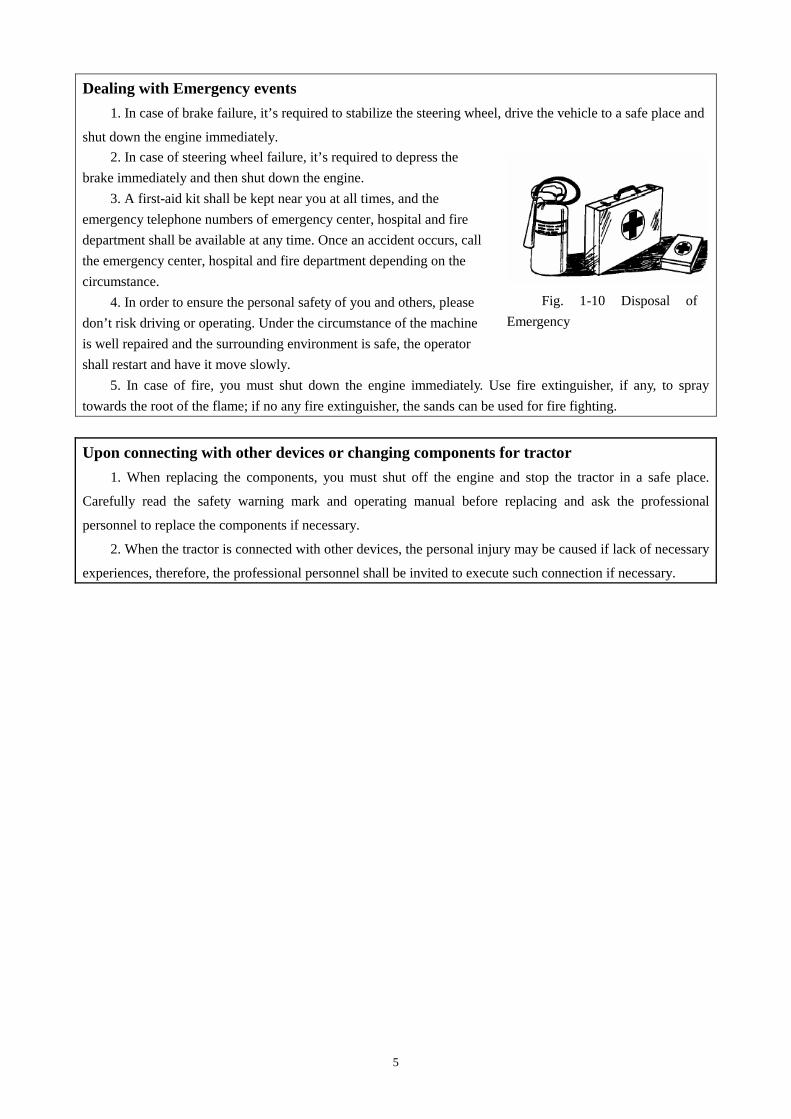
Fig. 1-10 Disposal of Emergency
Dealing with Emergency events 1. In case of brake failure, it’s required to stabilize the steering wheel, drive the vehicle to a safe place and
shut down the engine immediately. 2. In case of steering wheel failure, it’s required to depress the
brake immediately and then shut down the engine. 3. A first-aid kit shall be kept near you at all times, and the
emergency telephone numbers of emergency center, hospital and fire department shall be available at any time. Once an accident occurs, call the emergency center, hospital and fire department depending on the circumstance.
4. In order to ensure the personal safety of you and others, please don’t risk driving or operating. Under the circumstance of the machine is well repaired and the surrounding environment is safe, the operator shall restart and have it move slowly.
5. In case of fire, you must shut down the engine immediately. Use fire extinguisher, if any, to spray towards the root of the flame; if no any fire extinguisher, the sands can be used for fire fighting.
Upon connecting with other devices or changing components for tractor 1. When replacing the components, you must shut off the engine and stop the tractor in a safe place.
Carefully read the safety warning mark and operating manual before replacing and ask the professional
personnel to replace the components if necessary.
2. When the tractor is connected with other devices, the personal injury may be caused if lack of necessary
experiences, therefore, the professional personnel shall be invited to execute such connection if necessary.
5

Safety precautions
Correct use of battery 1. The gas overflowing from the battery is dangerous, therefore, the battery shall be kept away from open
fire(fire from match, lighter or cigarette, etc); the electric line
shall not have a short circuit and generate spark.
2. The battery is only for starting the engine and not for
other purposes.
3. When the battery is charged or changed, please read the
notice label on the battery.
4. When the battery is removed, the bond strap connecting
with negative terminal (-) shall be removed first. After battery is
mounted, the cable connecting with positive terminal (+) shall
be installed first.
5. When the battery is charged, it shall be removed from
the machine.
6. Prior to charging, please check whether the vent hole on
the battery cover is well ventilated, with ventilated surrounding
environment.
7. Properly select charging current according to rated
capacity of battery. After charging, please disconnect charging
source first and disconnect cable from the terminal of battery in
case the battery is detonated by electric firing.
8. Please don’t use any other batteries other than the one
designated by the machine.
9. It’s very dangerous to contact electrolyte (dilute
sulphuric acid). Promptly cleanse the eyes, skin & clothes
with clean water in case of contacting the electrolyte solution;
Flush the eye with water if it enters into the eyes and then go to
the doctor immediately. The following measures shall be taken in order to avoid damage:
① Wear safety goggles and rubber gloves.
②Avoid breathing smoke generated by the electrolyte;
③ Prevent the electrolyte solution splashing or leaking.
④Use correct parallel starting procedures.
Ensure the correct installation of anti-turnover bracket
If the anti-turnover bracket is disengaged or removed due to any reason, please make sure that all the parts and components are reinstalled correctly. Tighten the fixed bolt to its correct torque. If the structure of anti-turnover bracket is damaged due to overturn accident and bending, its protection function will be influenced, so the damaged anti-turnover bracket must be replaced and not be used any more.
Fig. 1-11 Use of battery
Fig 1-12 Danger of electrolyte
Fig. 1-13 Inspection of storage battery
+electrode -
electrode start
6

Safety precautions Correctly use the foldable anti-turnover bracket and safety belt
1. If the tractor has foldable anti-turning rack, you must keep the anti-turning rack at full extending and lock position. If the anti-turnover bracket is working in the fold position, you must drive the tractor with care. If anti-turnover bracket in the fold position, seat belt is prohibited to be used.
2. When the tractor returns to normal operating condition, you must timely lift the anti-turning rack to full extending position and fix it. When the anti-turnover bracket is at full extending or lock position, you must use safety belt.
3. If damage appears on the fastener, buckle or shrinker , the safety belt must be replaced. 4. You shall always check the safety belt and its fastener. Check whether the fastener is loose or the safety
belt is damaged, such as cutting port, scratch, and abnormal spoilage and wear. 5. If tractor doesn't have anti-turnover bracket or cab, safety belt is prohibited to be used.
Warning:
1. Please operate safely for sake of your life, property security and family happiness.
2. When the tractor starts up, the attention should be paid to whether there is obstacle on path,
anyone present between tractor and farm implements or trailer, to prevent from the sudden start of
tractor, action out of control, which will cause the unexpected danger.
3. Do not leave the driver seat to start and operate the tractor. Ensure that various gear shift
levers stay in the neutral position prior to the startup, and the power output shaft control handle and
front drive axle control handle stay at the disconnecting position, the lifter control handle put in the
neutral position, to prevent from the sudden start, which will cause the unexpected danger .
4. Do not start up the engine by the way of bridging over short circuit terminals, otherwise, the
tractor will automatically lose control on driving and cause the accidental danger when the gearbox is
engaged.
5. The pedal action should not have any hindrance; all the pedals must be free from obstacles and
able to back on home position. On the floor and under the pedal, there must not be any things hindering
the pedal travel. No rolling or slip objects may lay aside when stepping on the pedals. The extra foot
blanket or other mats are not allowed to lay around the pedals, so as to avoid the influence on the pedal
movement and cause the accidental risk.
6. While the tractor is moving, persons are not allowed to get on and off. During the running of
engine, no check and repair by crawling under the bottom of the tractor are permitted to prevent from
the accidental risk.
7. After parking and before getting down from the tractor, the driver must take out the key, set all
shift levers on the neutral position, and lock up the parking-brake handle to prevent the tractor from the
sudden startup, action out of control and accidental risk.
8. During the transportation, the L/R brake pedals must be interlocked together and control the
speed reasonably. When crossing the tunnels and the bridges, full attention must be paid to whether the
load is over the limited height. The sufficient deceleration must be made in advance while turning to
avoid the accident, overturn and collision.
7

Safety precautions
9. When going uphill or downhill, the lowest gear must be used and reasonably use the accelerator
to control . It is strictly prohibited for the tractor to shift on neutral gear or to glide downhill by stepping
on the clutch pedal. It is strictly prohibited to shift the gear on an up and down slope so as to avoid the
danger of overturn.
10. The sudden turn is not allowed while the tractor drives at high speed. Do not make the sudden
turn by the unilateral braking so as to avoid the danger of overturn.
11. When driving the tractor on the road, attention should be paid to the traffic sign and the traffic
law and rules should be strictly observed so as to avoid the accident.
12. In case of tractor displacement, the traffic rules should be strictly observed and the distance
between two vehicles should be kept at least 60m to avoid the collision resulting from accident.
13. The roadbeds near ditches, caves and dams are more fragile, the tractor's weight possibly
causes their crushes, please make a detour, and otherwise the accidental danger may arise.
14. The tractor is not allowed to be overloaded and overburdened. It is prohibited to run over limit
duty, which may cause the machine damage, even the casualty of present persons.
15. When tractor works at night, the good lighting equipment must be provided so as not to
influence the work efficiency of tractor and cause accidents.
16. When the tractor carries on the harvest or backyard work, the spark extinguish device must be
fixed on the exhaust pipe, in order to avoid fire accident.
17. When working on a rainy day, the operation speed must be reduced to avoid the rollover risks
due to the slippery path and ground.
18. When power output is working, the reliable connection and protection must be guaranteed to
prevent the moving parts from shaking off and hurting persons.
19. When hitching and towing the attached tools, the reliable and fast connection of each pin roll
must be guaranteed to prevent them from shaking off and causing the danger of collision. When
disconnecting the hitching and towing tools, ensure that all pin rolls are in disengaged status to avoid the
damage on the machine and human safety danger due to the misconnection.
20. When lifting, pay attention to the control of the engine throttle to avoid fast hoisting speed,
which may damage the machine or endanger the personal safety.
21. During the battery charge, make sure that the air vent of filling plug is unimpeded and far
away from the open fire. After charging, the power should be first cut off to avoid explosion.
22. The installation height allowed by the high voltage transmission line must be strictly observed,
in order to avoid dangerous accident!
23. When the tractors is used for harvest ,threshing and inflammable goods transportation, it must
be equipped with fire extinguisher so as not to avoid fire accident.
24. When tractor carries out transport operation, the user shall equip with fault warning marking
board. When the tractor has present fault and needs to carry out repair, please place the warning
marking board at least 30m behind the fault tractor to warn other vehicle for vehicle repair in the front
so as not to occur danger.
8

Safety precautions
Attention:
1. Bolts, nuts and easy loose components on each joint, e.g. the nuts on the front/rear drive wheels
and connecting nut of the steering draw rod should be frequently checked. If loose, screw it tightly to
avoid dangerous accident.
2. When the power output shaft is working, the safety shield of power takeoff shaft has to be
installed. Persons are strictly prohibited to approach the power takeoff shaft. When the power takeoff
shaft is on load, the tractor is not allowed to make the sudden turn in order to avoid the damage on the
universal joint or the power takeoff shaft; When the Power takeoff shaft is not in use, the handle should
be made on separate position to avoid dangerous accident.
3. After stopping the tractor, the driver cannot leave the tractor before the engine is shut down, in
order to avoid sudden start of the tractor, action out of control which may lead to accident.
4. When parking the tractor on the slope, the hand brake handle should be in active state, let the
engine shut down, put on gear (Uphill position on front gear, downhill on reverse gear position), the
parking brake must be used with triangle block chocking the rear wheels so as to prevent from tractor!/s
action out of control and the accidental risk.
5. The installation and adjustment of tires can be carried out by the experienced persons with
special tool. The wrong installation of tires may cause serious accident.
6. When cleaning the water tank, clean work should be made after cooling down of water tank
and engine flameout so as not to cause the scalding accident and damage to water tank.
7. Before the installation and use of optional parts, replacement parts or hitching implements,
please be careful and carefully read the safety warning mark and the operation manual.
Important: 1. For the tractor from the new production or after the overhaul, the running-in has to be made
according to the requirements of tractor's running-in so as to avoid affecting the normal service life of
tractor.
2. The tractor should use various kinds of solution strictly according to the requirements. The fuel
must be subject to at least 48h's (hours) sediment and purification process. Only having passed through
the filtration by filter at the same precision as oil absorption filter of lifter, the lubricating oil in the
transmission system can be added so as not to affect the service life of related part and operating
performance of tractor.
3. Prior to the startup of tractor, the oil system, electric circuit and coolant have to be examined;
After the startup, the attention has to be paid anytime to the readout of various instruments and the
normal operation of each part.
4. Before the power takeoff shaft actuates the farm implements, the matching rationality between
the tractor and driven farm implements should be inspected. When tillage is performed, the included
angle between the power takeoff shaft and the universal joint drive shaft should not be bigger than 15°
(degree); When the hydraulic operating control is normal, and after the farm implements has been lifted
at the curve of field edge, the included angle between the power takeoff shaft and the universal joint
9

Safety precautions
drive shaft should not be bigger than 20° (degree); It is prohibited to dig the rototiller into field prior to
the power takeoff connection, for this will severely damage the rototiller and the tractors!/ clutch [To
increase the work efficiency, the power supply can not be shut off at the time of turning, however, the
lifting height of tools must be maintained at ca. 200mm(millimeter) above the ground].
5. When the temperature in winter is lower than 0 ℃ (degree Celsius), the -freezing fluid must be
used so as not to freeze water tank, engine and etc.
6. The front drive axle of tractor can be used only at the time of farmland work, on muddy road and
skidded tires; the use on other cases is not allowed, and otherwise it is easily to cause the premature wear
of tire and the transmission system.
7. During the running process of tractor, the driver's feet are not allowed to place on the brake pedal
or the clutch pedal so as to avoid the premature wear of the brake or the clutch.
8. When the tractor displaces with attached agricultural machinery, the upper lever of the
suspension unit should be adjusted to the shortest condition, and the limit lever adjusted to prevent the
agricultural machinery from swinging. At the meantime, the locking nuts of upper and limit levers must
be tightly screwed to ensure driving security and avoid the damage risk on the machine and agricultural
machinery.
9. When the tractor shifts with the farm implements hanging on it, the farm implements position
should be fixed. The farm implements must be lowered to the ground when the driver leaves the tractor
in order to avoid the damage risk on the machine and farm tools.
10. For the tractor maintenance, the qualified parts must be used so as not to affecting the normal
service life of tractor.
Twist off the radiator cap
When the engine remains on warm state, twist off the radiator cap with
care. After several minutes idling, shut off the engine and cool it down, twist
the radiator cap to the first gear position, and then take it out after the pressure
has been reduced.
Fig.1-14 Twist off the radiator cap
Maintenance of electric parts
1. Take out the electrical locking switch key.
2. Cut off the master switch of battery power and then repair the electric
parts.
3. When using electric welding to repair the tractor, disconnect the battery
ground wire. Unplug the big connecting wire of computer controller of engine
hydraulic part, otherwise it may easily damage the battery, controller and
combination instrument.
Fig. 1-15 Maintenance of electric parts
10

Safety precautions
In case of abnormal phenomenon occurring on the tractor
1. The tractor is not allowed to work “with defects”. In particular, when
lack of oil pressure, excessively low oil pressure, over-high water
temperature or unusual sound and smell occur, stop the machine in time for
check and troubleshooting.
2. During the lubrication maintenance and adjustment on field, the
engine should be shut down. Fig. 1-16 In case of abnormal
phenomenon occurring on the tractor Safety rules of unattended tractor
1 Shift to neutral position and move the hydraulic control handle to middle position.
2. Lifting device or traction articulated device is placed at the lowest position.
3. Engage parking brake.
4. Take down engine switch key.
5. If the tractor is stopped on the slope, a triangle stopper must be used to stop the rear tire.
1.2 Safety warning mark
Warning:
1. The safety warning marks should remain clear and easy to read. When dirty, wash them with soapy
water and clean them with soft rag;
2. When the safety warning marks are lost or unclear, it is necessary to contact the sales department or the
manufacturer in time for replacement.
3. In case of replacing the parts with attached safety warning mark, the replacement of safety warning
mark should be made at the meantime.
4. The safety warning mark, where the prompts involve to the personal safety, must be strictly complied.
Meaning: When the tractor is working, keep away from its hot surfaces to avoid
personal injury;
Pasting position: Outer side of damper, flank of water tank.
Fig 1-17 Safety warning mark IV
11

Safety precautions
Meaning: Keep a safe distance from the tractor to avoid personal injury;
Pasting position: rear side of mudguard.
Fig 1-18 Safety warning mark II
Meaning: Do not ride in a place other than passenger seat to avoid obstructing the
driver's line of sight, causing personal injury;
Pasting position: Front side of the left and right mudguard. Fig 1-19 Safety warning mark VI
Meaning: When the lifting rod control mechanism works, stay far away from the
effective space of lifting lever, so as to avoid personal injuries!
Pasting position: rear side of mudguard.
Fig 1-20 Safety warning mark III
Meaning: Before repair, maintenance and adjustment, shut off the engine and remove the
ignition key in accordance with the requirements of the operation manual to avoid personal
injury;
Pasting position : the front of the instrument panel
Fig 1-21 Safety warning mark I
Meaning: when the engine is running, do not open or remove the protective cover and do not reach into the
working area to avoid personal injury;
Pasting position: on the engine hood
Fig 1-22 Safety warning mark IX
12

Safety precautions
Meaning: The driver must start the engine on the driver’s seat. Do not start the engine in a
short-circuited manner at the starter to avoid injury;
Pasting position : the front of the instrument panel
Fig 1-23 Safety startup mark
Meaning: Please read the manual to understand the meaning of the non-lettered safety symbol
so as to avoid personal injuries.
Pasting position : the front of the instrument panel
Fig 1-24 Read the manual mark
Meaning: When maintaining the battery, please refer to the operation manual for correct
maintenance process to avoid personal injury.
Pasting position: On the surface of the battery
Fig 1-26 Battery mark
Meaning: See Fig. 1-27
Pasting position: Near the electric box
Fig 1-27 Fuse safety warning mark
Meaning: Only when all parts of machine have fully stopped can it be contacted so as not to cause personal
injury.
Pasting position: On the PTO protective cover.
Fig 1-25 PTO safety mark
13

Safety precautions
Meaning: See Fig. 1-28
Pasting position: Near the oil filler of fuel tank
Fig 1-28 Fuel filling anti-fire mark
Meaning: See Fig. 1-29
Pasting position: Near the power output shaft
Fig 1-29 PTO safety mark
Meaning: See Fig. 1-30
Pasting position: Surface of air brake tank
Fig 1-30 Air brake warning mark
14

Safety precautions Meaning: See Fig. 1-31 Pasting position: Rear transverse board, floor
Fig 1-31 Safety warning mark IX
Meaning: See Fig. 1-32 Pasting position: Near the steering fluid tank
Fig. 1-32 Fluid level marking
Meaning: See Fig. 1-33;
Pasting position : the front of the instrument panel
Fig 1-33 Safety starting warning mark IX
15

Safety precautions
Fig.1-34 Pasting Schematic for warning marks
16
Product Mark
1-Complete machine No. Fig. 2-3 Factory No.
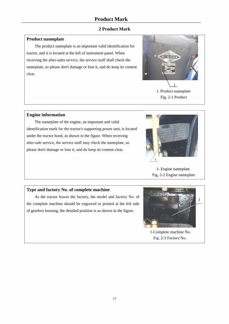
2 Product Mark
Product nameplate The product nameplate is an important valid identification for
tractor, and it is located at the left of instrument panel. When
receiving the after-sales service, the service stuff shall check the
nameplate, so please don't damage or lose it, and do keep its content
clear.
Engine information The nameplate of the engine, an important and valid
identification mark for the tractor's supporting power unit, is located
under the tractor hood, as shown in the figure. When receiving
after-sale service, the service stuff may check the nameplate, so
please don't damage or lose it, and do keep its content clear.
Type and factory No. of complete machine As the tractor leaves the factory, the model and factory No. of
the complete machine should be engraved or printed at the left side
of gearbox housing, the detailed position is as shown in the figure.
1- Engine nameplate
Fig. 2-2 Engine nameplate
1. Product nameplate Fig. 2-1 Product
1
17

Operation Instructions 3 Operation instruction
Attention: Correct operation of the tractor can give full play to its efficiency, reduce wears and
prevent accidents so that the operator could achieve high-quality, efficient, low-cost and safe field and
road work.
Table 3-1 Commonly Used Symbols
Symbol Meaning Symbol Meaning Symbol Meaning
Safety alert
symbol
Four-wheel
drive
Horn
High beam
lamp
Low beam lamp
Fast
Engine oil
pressure
Battery
charging
condition
Slow
Steering
indicator
Scrubber
Position lamp
Engine
preheating Rear wiper
Wiper
Air filter
blocking alarm
Oil filter
blockage alarm
Air brake
failure / fault
Engine coolant
temperature
Fuel level
Parking brake
18

Operation Instructions
Differential lock
Hazard
indicator light
Brake fluid
level alarm
3.1 Product description
This manual introduces the use, technical maintenance, adjustment, faults and troubleshooting of the
LOVOL-TD wheeled tractor.
LOVOL-TD series wheeled tractor is a multi-purpose large scale agriculture tractor. It is featured with
compact structure, easy operation, flexible steering, high towing force and convenient maintenance etc.
3.2 Tractor operation mechanism and instrument
3.2.1 Tractor operation mechanism
Fig. 3-1 Tractor operation mechanism
1. PTO control handle; 2. Parking brake control handle; 3. Main clutch pedal; 4. Flameout pull wire handle
5. Right and left brake pedal; 6.Foot accelerator control pedal; 7. Auxiliary clutch control handle; 8. Distributor
control handle 9. Main gear lever; 10. Auxiliary gear lever; 11. Hand accelerator control pedal;
19

Operation Instructions 3.2.2 Instrument and switches
Instrument and switches
The instrument cluster includes a water temperature
gauge, a fuel indicator, an engine tachometer, an engine
oil pressure meter, and a steering indicator lamp,
high-beam and low-beam indicator lamps, a position
indicator lamp, a charging alarm lamp, an air pressure
warning lamp for easy monitoring of vehicle operating
condition at any time.
Fig. 3.-2 Instrument and switches
Important
While the tractor is working, the driver should always pay attention to the various instruments and
indicator lamps, and if any abnormality occurs, stop it immediately for maintenance.
Engine Tachometer
After starting the engine, the indicated value
shows operating speed of the engine while that in the
box shows operating hours of the engine.
Fig. 3-3 Engine Tachometer
Water temperature gauge
It indicates engine coolant temperature with scales with the pointer moving
from left to right. The red area is high temperature area.
Fig. 3-4 Water temperature gauge
1. Combination instrument assembly
2. Right side rocker switch combination
3. Ignition lock
4. Left side rocker switch combination
Ordinary
Practical power
Ordinary
Practical power
Ordinary
Practical power
20

Operation Instructions
Fuel gauge
Fuel gauge indicates fuel volume in the fuel tank with
scales. When the pointer pointing at the rightmost position,
it is indicated that the fuel tank is filled with fuel; when the
pointer pointing at the left red area, it is indicated that there
is insufficient fuel in the tank and please refuel immediately.
Fig. 3-5 Fuel gauge
Oil pressure gauge
Oil pressure gauge indicates oil pressure with scales.
When the pointer pointing at silver gray area in the
middle, it is indicated that oil pressure is normal; when
the pointer pointing at red area, it is indicated that oil
pressure is abnormal and carry out overhaul immediately.
Fig. 3-6 Oil pressure gauge
Charging indicator lamp (red)
After starting the engine, this lamp should go out to indicate the battery charge is normal. If
the indicator lamp does not go out, carry out overhaul accordingly.
Fig. 3-7 Charging indicator lamp
Air pressure warning lamp (red)
In the case of a model with an air brake, when the air brake system pressure is lower than
0.4MPa(Megapascal), this lamp lights up to indicate brake air circuit faults or air
pressure warner breakdown which should be overhauled at once. Switch on the key
with the engine shutdown, if the pressure is insufficient, the lamp will light up
normally.
Important: Before the engine working, the ignition key should be at ignition position and check whether
the above two lamps come on. Otherwise, the bulb is damaged or circuit failure will occur, please
immediately repair.
Ordinary
Practical power
Ordinary
Practical power
Fig. 3-8 Air pressure
warning lamp
21

Operation Instructions
Position indicator lamp (green)
In the case of tractor stopping during running on a highroad at night, it is necessary to turn on
clearance lamps and place the lighting switch at position “1”to guarantee driving safety and
remind drivers in vehicles in front and behind of the parking tractor. At the moment,
clearance lamps of position indicator lamps light up.
Fig. 3-9 Position indicator lamp Parking brake indicator lamp (red)
When pulling up the hand brake, the lamp comes on, and when pulling down the hand brake,
the lamp comes off.
Fig. 3-10 Parking brake indicator lamp
Brake oil pot oil level low alarm lamp (red)
The lamp turns on. It indicates that the oil level in the brake oil pot is low, so it is required to
refill brake oil in time.
Fig 3-11 Brake oil pot oil level low alarm lamp
Headlamp high beam indicator lamp (blue)
When the lighting switch and dimmer switch are locating at position “2”, this lamp lights up. It
indicates that operating headlamps are high beams at the moment.
Fig. 3-12 Headlamp high beam indicator lamp
Left turn signal lamp (green)
In the case of left turn of the tractor, switch on the left turn signal switch, this lamp lights up.
Fig. 3-13 Left turn signal lamp
Right turn signal lamp (green)
In the case of right turn of the tractor, switch on the right turn signal switch, this lamp lights up.
Fig. 3-14 Right turn signal lamp
22

Operation Instructions
Preheating indicator lamp (yellow)
This lamp light up during tractor preheating.
Fig. 3-15 Preheating indicator lamp
Left rocker switch combination
1. Dimmer switch
2. Lighting switch
3.Ceiling and rear lamp
switch
4.Wiper switch (for the
model with cab)
Dimmer switch
Position “2”: high beams light up. Position “0”: low beams light up. Position “1”:
standby. Change-over between high beams and low beams are controlled by the
lighting switch.
Fig. 3-17 Dimmer switch
Lighting switch
When it is locating at Position “0”, power supply is cut off. Position “1”: position lamp
lights up. Position “2”: headlamps are power-on, when the switch is located at this
position, headlamps can be controlled by the dimmer switch for high beam and low
beam change-over.
Fig. 2-15Fig.3-18 Lighting switch
Switch for ceiling lamp and rear lamp
Position “0”, power supply is cut off. "1" position: The ceiling lamp is on (Being used
where a cab is provided). Position “2”: rear lamps light up.
Fig. 3-19 Ceiling and rear lamp switch
Fig. 3-16 Left rocker switch combination
23

Operation Instructions
Wiper switch
Position “2”, wiper operates quickly; Position “1”, wiper operates slowly; Position
“0”, wiper is reset and stops operating.
Fig. 3-20 Wiper switch
The right side rocker switch assembly consists of the following two kinds of switches.
Right side rocker switch combination
Fig. 3-21 Right side rocker switch combination
Hazard warning switch
Position "1": All the front, rear, left and right steering lamps, the right and left steering lamps on the
instrument and the indicator on the hazard warning switch will light up. When the
tractor stops on the road due to failures or it needs warning vehicles and pedestrians
around due to other reasons, this function should be used in order to avoid accidents.
Fig. 3-22 Hazard warning switch
Steering switch
Position 2: The right steering lamps will be switched on; Position 0: Cut off power;
Position 1: The left steering lamps will be switched on.
Fig. 3-23 Steering switch
Horn switch: The horn switch is located on the steering wheel. When using the horn, press down the center cover
plate of the steering wheel to switch on the horn switch.
1. Hazard warning switch 2. Turn signal switch
24

Operation Instructions
Ignition lock:
Insert the key into ignition lock and turn the key clockwise to positions
as follows:
Turn it to OFF position (power-off)to switch off the vehicle
circuit power supplyand the key can be inserted or pulled out;
Turn it to ACC position (auxiliary component control) to power
on auxiliary electrical components (such as: air heater, wiper, fan, horn
switch, etc.) and the auxiliary electrical component circuit is power-on;
Turn it to ON position (ignition position) to switch on the vehicle power supply and the vehicle
circuit is power-on;
Turn it to H position (preheating position) and the engine glow plug (or preheating system ) starts to
operate;
Turn it to ST position (start position) to start the engine; after starting the engine, release it immediately
and the key returns to ON position automatically. At the moment, ON position and ACC position are connected
simultaneously and vehicle circuit is power-on;
Main power switch:
During startup of the tractor, turn the operating handle of the main
power switch in clockwise direction, turn on the main power switch for
energization; otherwise, the complete vehicle cannot be started;
After flame-out of the tractor, turn the operating handle of the main
power switch in counter-clockwise direction to disconnect the power
supply to avoid self-discharging of the battery. During maintenance of
the vehicle, the switch must be off.
Alarm lamp switch: The alarm lamp switch of of cab model is located on the right of air
conditioner switch of top left, and the alarm lamp switch of safety frame model is located on
the right rocker switch. It is only necessary to press the switch when using the
switch of alarm lamp.
Fig. 3-25 Ignition lock
Fig. 3-24 Alarm lamp
switch
Fig. 3-26 Main power switch
25

Operation Instructions 3.3 Start of engine
Note: Before use, serious and comprehensive inspection shall be made on the tractor to eliminate
the hidden dangers and effectively avoid dangerous accidents.
3.3.1 Preparations before engine start
● Before start, careful checks should be made to ensure that all parts are reliably tightened, all controls
work normally and all tube joints are tightened without any oil, water or gas leakage;
● Check the lubricant level in the engine oil sump, gearbox, rear axle and hydraulic system. Fill the
radiator up with cooling water. Fill the fuel tank up.
● Check the gearbox control handle, PTO handle. Position the
main gear lever, PTO handle, front drive shaft control handle
respectively to neutral gear position. Position the distributor control
handle to lowering position
● Pull the locking device of the flameout cable to loosen the
wire, and at this time, the injection pump is at the position of oil
supply;
● Position the hand accelerator at half state, as shown in
fig.3-25.
● As to the new, overhauled or long-period storage tractor, before starting, please empty the air in oil (fuel)
pipe to ensure diesel engine smooth starting.
The method is as follows: loosen the air bleeding screw on the diesel filter, use hand pump to empty the air
of fuel pipe from the fuel tank to diesel filter until there is no bubble emerged in drained fuel. Then, tighten
the bleeder screw of the diesel filter, unscrew the bleeder screw on the injection pump and deflate similarly as
above until the discharged fuel is free from any bubble.
Important:
1.The debris should be regularly cleaned from the water tank meshes, so as to avoid engine failure
due to poor heat dissipation;
2. After the tractor is equipped with a knapsack type harvester, it is recommended that an auxiliary
cooling device will be installed at the proper position so that the engine could be able to continuously
work for a long time because of the poor heat dissipation.
3.3.2 Start of engine
Fig. 3-27 Hand accelerator
26
Operation Instructions
Attention:
Before starting, please ensure the main/auxiliary gear lever and front drive control lever are
positioned at neutral position, the distributor control lever should be positioned at lowering position to
avoid tractor suddenly starting.
Important:
1. After starting, please immediately let your hand go to allow the ignition key automatically return
back to ON (see ignition lock picture). Otherwise, started engine will reversely make the starting motor
started, causing damage of starting motor.
2. Engine should be of good starting performance. If ambient temperature is not less than -5℃, the
engine starting time should be within 5s. At any state, engine starting time should not be more than 15s.
During repeatedly starting, each interval should not be less than 2 min. If the engine could not be started
for successively 3 times, please find out cause and start again.
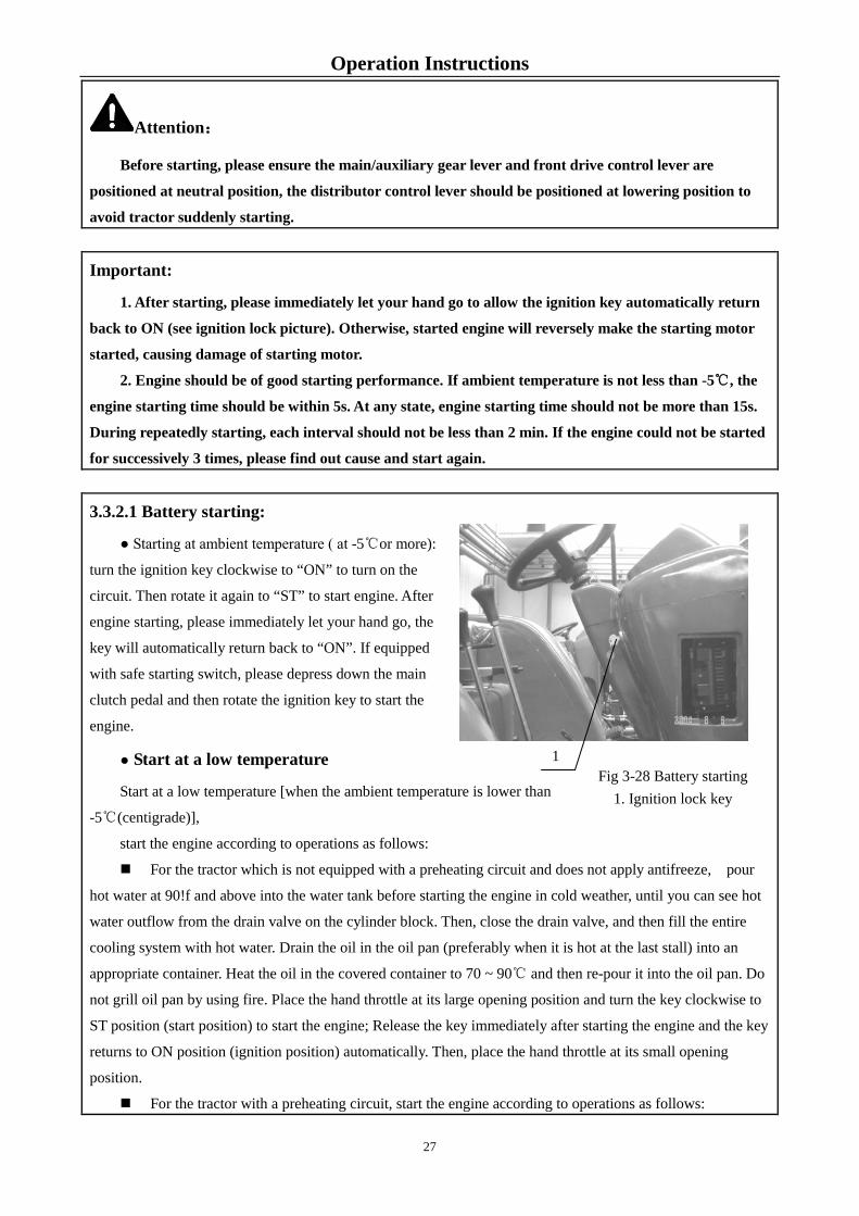
3.3.2.1 Battery starting:
● Starting at ambient temperature ( at -5℃or more):
turn the ignition key clockwise to “ON” to turn on the
circuit. Then rotate it again to “ST” to start engine. After
engine starting, please immediately let your hand go, the
key will automatically return back to “ON”. If equipped
with safe starting switch, please depress down the main
clutch pedal and then rotate the ignition key to start the
engine.
● Start at a low temperature
Start at a low temperature [when the ambient temperature is lower than
-5℃(centigrade)],
start the engine according to operations as follows:
For the tractor which is not equipped with a preheating circuit and does not apply antifreeze, pour
hot water at 90!f and above into the water tank before starting the engine in cold weather, until you can see hot
water outflow from the drain valve on the cylinder block. Then, close the drain valve, and then fill the entire
cooling system with hot water. Drain the oil in the oil pan (preferably when it is hot at the last stall) into an
appropriate container. Heat the oil in the covered container to 70 ~ 90℃ and then re-pour it into the oil pan. Do
not grill oil pan by using fire. Place the hand throttle at its large opening position and turn the key clockwise to
ST position (start position) to start the engine; Release the key immediately after starting the engine and the key
returns to ON position (ignition position) automatically. Then, place the hand throttle at its small opening
position.
For the tractor with a preheating circuit, start the engine according to operations as follows:
1 Fig 3-28 Battery starting 1. Ignition lock key
27

Operation Instructions Place the hand throttle at large opening position and turn the key clockwise to H position (preheating
position ) and hold for (15~20) s (second) and then turn the key to ST position (start position) to start the
engine; Release the key immediately after starting the engine and the key returns to ON position (ignition
position) automatically. Then, place the hand throttle at its small opening position.
Tow start:
If starting engine by towing tractor, you should engage 3-gear or 4-gear of high-speed gear. To ensure
safety, the speed of towed tractor should not be higher than 15km/h.
Important: When a towing tractor is used for starting, immediately step down the main clutch pedal once
the engine starts working, and narrow the accelerator to prevent engine flameout.
3.3.3 Operation of engine
● After engine starting, please immediately decrease the accelerator to allow the engine at idle state. At
this time, check the engine oil pressure and ensure it is not less than 98kPa, then the oil pressure indicating
lamp will go out.
● Once the engine starts, do not let it run under full load immediately, but under no load at a medium
speed to warm up. Only when the coolant temperature is above 60℃ can you use the maximum speed for
full-load work.
● You should slowly increase or decrease the engine speed and load, especially when the engine has just
been started, it is prohibited to force the !0accelerator!1 for high-speed operation.
● During engine running, please frequently check the oil pressure and coolant temperature. At normal
work, the coolant temperature should be within (85~95) ℃, and oil pressure should be within (0.3~0.5) MPa.
Important: At any state, oil pressure should not be less than 0.1MPa to avoid damage of engine.
3.4 Starting of tractor
● When the engine is at low speed status, step down the clutch pedal, and then place the transmission gear
lever to the desired gear;
● Push the hand brake handle downward, loosen the
parking brake;
● Sound the horn and make sure there is no barrier
around.
● Increase the engine speed gradually, and release the
clutch pedal gradually to allow the tractor to start
smoothly. After starting, release the clutch pedal quickly
to prevent the clutch from being ground;
● Speed up the engine gradually until the tractor reaches the desired operating speed;
Fig. 3-29 Starting of tractor
28

Operation Instructions
● Do not slow down the tractor by engaging the clutch half. When the tractor is moving, when you are not
shifting, do not rest your foot on the clutch pedal. This can cause your release lever and friction plates to wear
out faster.
Important:
1. It is not allowed to start with high gears engaged to avoid gear impact of the gearbox drive gear
and clutch early wears.
2. Prior to starting, it is necessary to release the parking brake to avoid operating component
damages.
3. It is necessary to release the main clutch via depressing the clutch pedal in the case of gear
engagement or gear shift to avoid gear impact of the gearbox drive gear and clutch early wears.
3.5 Tractor Steering
If tractor steering on the road, firstly press the horn switch on the core of steering wheel to sound warning,
then do the steering. If the speed is high, firstly slow down, slowly and early turn the steering wheel with less
times of returning back steering wheel. If sharp turning, lately and quickly turn the steering wheel with more
times of returning back steering wheel.
In the case of tractor small turning or turning on soft ground, there may be steering failure due to front
wheel sideslip. At the moment, turn the steering wheel and depress the brake pedal at the corresponding side
simultaneously to help steering.
Warning: 1. It is not allowed apply single-side brake for a sharp turn when the tractor is running with a high
speed;
2. When turning the front wheel at smooth angle, if steering relief valve sounds squeak during
acting, slightly return the steering wheel back to avoid hydraulic system damage which is caused by
overload for long period, resulting in steering failure occurs.
3. Before turning or backing in the field work, first do have the underground parts of the
agricultural machinery rise out of the ground so as not to damage the farm implements or cause casualty
accidents.
3.6 Tractor gear shift
Main and auxiliary gear shift is respectively controlled by 2 pieces of control handle. Main gear lever A
can get 4 gears (1,2,3,4) and auxiliary gear lever B can get 2 forward speed section (L is low speed section, H is
high speed section) and 1reverse speed section R.
29

Operation Instructions
3.6.1 8+4 gears and 16+8 creeper gears:
Main gear lever A Auxiliary gear lever B
Fig 3-30 Tractor gear shift
Depress down the main clutch pedal and push the auxiliary gear lever B from the neutral gear to the left. If
continuously pushing forward, you can get low speed section L. If continuously pushing backward, you can get
high speed section H. If you push the auxiliary gear lever B from the neutral position to the right and then to the
forward, you can engage the reverse gear R.
Depress down the main clutch pedal and push the main gear lever A from the neutral gear to the left. If
continuously pushing forward, you can engage 2nd gear. If continuously pushing right from the neutral
position, then backward, you can get 3rd gear. Push forward, you can engage 4th gear.
If your tractor is equipped with creeper gear, the high/low speed handle is mounted on the center-right side
of floor with the center gear position as neutral gear. If pulling the creeper gear handle upward, you can get low
speed gear. If pressing the creeper gear handle downward, you can engage the high speed gear. If combined
with said main and auxiliary gear levers, you can get 16 forward gears and 8 reverse gears.
3.6.2 16+8 shuttle type gear shift:
Main gear lever A Auxiliary gear lever B
Fig 3-31 Tractor gear shift
Depress down the main clutch pedal and push the auxiliary gear lever B from the neutral gear to the left. If
continuously pushing forward, you can get high speed section H. If continuously pushing backward, you can
get reverse gear R. If you push the auxiliary gear lever B from the neutral position to the right and then to the
forward, you can get the low speed section L.
Depress down the main clutch pedal and push the main gear lever A from the neutral gear to the left. If
continuously push forward, you can engage 1st gear. If continuously push forward, you can get 2nd gear. If you
push from the neutral position to the right and then to the backward, you can engage the 4th gear.
30

Operation Instructions
A high/low speed handle is provided at right part of the floor. The middle position is neutral gear. Pulling the
handle upward has the tractor engaged in the low speed gear, and pushing the handle downward has the tractor
engaged in the high speed gear. If combined with said main and auxiliary gear levers , you can get 16
forward gears and 8 reverse gears.
By selecting correctly the working speed of tractor, we can not only obtain the best productivity and
economy, but also extend the service life. While in work, we should not frequently overload the tractor, but give
the engine a certain power reserve. For the selection of speed for tractor field operations, it is preferred to keep
the engine running with the load of 80% of its rated one approximately. If the tractor works with light load at a
comparatively low working speed, we can choose a higher Gear-1 speed at a small accelerator to save fuel.
Important:
1. When the engine is running, have the main clutch pedal depressed thoroughly before gearshift,
and after several seconds, change the gear again, so as to avoid "gear crush" resulted from poor
engagement of the engagement sleeve of the gearbox,
2. Only the tractor is motionless, you may engage the reverse gear.
3. Do not place your hand on the gear lever during tractor running or pressure from the hand may
be delivered to the shift fork in the gearbox and this will lead to premature wears of the shift fork.
3.7 Operation of differential lock
Differential lock operation
During driving or operating, if the tractor cannot move
forward due to trapping or unilateral drive slipping, follow the
steps below to engage the differential lock so that the left and
right drive shafts could be rigidly connected and rotated at the
same speed to have the tractor move forward away from the
slippery section.
● Depress the main clutch pedal and put the gear lever to
a lower gear;
● Pull the throttle control lever to the position of the
maximum oil supply;
● Depress the differential lock control pedal with your right foot;
● Release the clutch pedal gradually to allow the tractor to start smoothly.
● After driving out of the slippery district, release the differential lock pedal and unlock the differential
lock automatically. Important: In normal running and turning, it shall be strictly prohibited to use the differential lock so as
Fig 3-32 Operation of differential lock
31

Operation Instructions
to avoid mechanical damages and accelerated tire wears.
3.8 Use of front drive axle
In the case of heavy-duty operation in the field or operation in the soft wet soil, the 4WD tractor may be
unable to provide a sufficient traction only relying on the rear-wheel drive. Then, to increase the traction,
engage the front drive axle to reduce slippage, thereby enhancing the adaptability of the tractor operation. In
order to connect and separate the front drive axle, the following control procedure should be abided by:
3.8.1 Attachment of front drive axle
Depress the main clutch pedal and shift the transmission into the desired gear, and then release the clutch
pedal gradually. Wait until the tractor moves slightly, and then pull up the control lever of the front drive axle to
make the 2WD change into 4WD.
3.8.2 Disconnection of front drive axle
Depress down the main clutch pedal, push the front drive axle control handle downward to make the 4DW
change into 2DW.
Important:
1. Important: when tractor works on hard ground, front drive axle is not allowed to be connected,
otherwise it can cause the premature wear of front tires and increase fuel consumption. Engage the front
drive axle only when driving on slippery roads in rainy and snowy weather, as well as on a deep uphill
which can cause the rear tires to slip. When tractor is driven out of difficult section, front drive axle
should be separated.
2. During transport operation, the tractor!/s front tires wear out faster and left and right tread
patterns wear unevenly. Therefore, you can rotate the left and right tires as the circumstances may
require.
3.9 Brake of tractor
In general case, we should reduce the throttle firstly, depress the clutch pedal, and then gradually depress
the brake pedal to make the tractor stop steadily.
In case of emergency stop, we should depress the clutch
and brake pedal at the same time, instead of stepping down the
brake pedal alone to avoid the sharp abrasion of the brake
friction plates or the engine flameout.
When applying the brake with a trailer, adjust the length
of the brake valve rod, and then brake the trailer before
braking the tractor.
32

Operation Instructions
Left/right brake pedal interlock
In normal running, an interlocking plate should be applied to lock the left and right brake pedals together.
Fig. 3-33 Brake of tractor
Warning: 1.It is necessary to check the brake oil reservoir for sufficient oil volume and check brake line for oil
leakage prior to every driving. If there is little oil in the oil reservoir or oil leakage in the line, find out the
cause and troubleshoot timely. Otherwise, there will be major accidents like brake failures.
2. In the case of normal tractor running, left and right brake pedals should be interlocked to avoid
tractor deviation and even rollover.
3.10 Tractor parking and engine flameout
Decrease the accelerator to reduce the running speed;
Depress the clutch pedal and brake pedal at the same time, lock up the brake handle, and put shift
lever to neutral position after the tractor is stopped;
Release the clutch and brake pedals, and decrease the accelerator to idle the engine;
Pull the flameout rod backward, the oil pump will stop feeding, the engine will stop immediately, and
then push back to the position of oil feeding;
Turn the ignition key to OFF to switch off all the power supplies.
Attention:
1. After stopping the tractor, the driver cannot leave the tractor before the engine is shut down, in
order to avoid sudden start of the tractor, action out of control which may lead to accident.
2. When it is inevitable to park on a slope, implement gear engagement (for upslope position,
apply forward gear engagement while for downslope position, apply reverse gear engagement) and make
sure to apply parking brake and wedge rear wheels with triangle wedge blocks to avoid tractor sudden
start and out of control as a result of self actions which may bring unexpected dangers.
Important:
1. When air temperature is lower than 0℃ (centigrade) in winter, for the tractor without
antifreeze, its water tank should be drain valve should be opened under the condition of engine idling
and water coolant for the engine should be drained completely through the drain cock and then shut
down the engine to avoid frost cracks of the engine body as a result of water coolant freezing.
2. If the outlet of radiator is higher than inlet of water pump, it is recommended to open the drain
switch to avoid the remained water in the outlet pipe of radiator freezing the pipe. Meanwhile position
33

Operation Instructions
the flameout position to off, and then use battery to drag engine running for 2-3times with less than 15s
each time and interval of 2-3min to drain the water in the pipe.
3.11 Adjustment of wheel track
3.11.1 Front wheel track adjustment (non-stepless adjustable wheel track type)
● Front wheel track adjustment of 2DW tractor: put the tractor front axle on the jack stand, dismantle the
lock bolt 1,2 from the left and right main and auxiliary sleeves.
Then remove the lock bolt 4 and cylinder mounting bolt 3. Adjust
the auxiliary sleeve, cylinder position and tie rod to desired
location. At last reinstall and lock all removed bolts. There are 4
kinds of front wheel track to be selected: 1385mm, 1485mm,
1585mm, 1685mm.
Fig.3-34. Tractor front axle
● The front wheel track of 4DW could be adjusted by changing joint position of rim and spoke. You can
get 4 kinds of wheel track 1610mm, 1710mm, 1810mm, 1950mm.
Fig.3-35 Front wheel track adjustment (unit: mm)
When the front wheel track is adjusted to the minimum value, the front axle should be adjusted as follows
accordingly:
a. Remove the front wheel mudguard;
b. As shown in Figure 3-33, screw a M10×20 bolt into the adjusting threaded holes of the left/right
steering knuckle of the front axle, respectively, so as to limit steering angle of the front wheels by adjusting
34

Operation Instructions
screw-in length of the bolts; the front wheelፉ´
3.11.2 Rear wheel track adjustment (non-stepless adjustable wheel track type)
Adjusting method: the 5 wheel tracks could be obtained via different connections of spoke, hub and rim.
Fig.3-36 Rear wheel track adjustment (unit: mm)
Note: When the rear wheel track is adjusted from 1608 mm to another value, the rear counterweight
cannot be used, and the user should select a rear wheel track value according to actual working
conditions.
3.11.3 Adjusting wheel track of the vehicle model with stepless wheel track adjustment.
3.11.3.1 Adjustment of front wheel track
● 2DW tractor: put the tractor front axle on the jack stand,
dismantle the lock bolt 1,2 from the left and right main and
auxiliary sleeves. Then remove the lock bolt 4 and cylinder
mounting bolt 3. Adjust the auxiliary sleeve, cylinder position and
tie rod to desired location. At last reinstall and lock all removed
bolts. 6 kinds of wheel track are available for selection by
changing the bolt position instead of turning the spoke over:
1595mm、1695mm、1795mm、1895mm、1995mm、2095 mm.
Further 6 kinds of wheel track i.e. 1651mm, 1751mm, 1851mm, 1951mm, 2051mm, 2151mm are available for
selection by turning the spoke over and changing the bolt position.
Fig.3-37 Front axle of stepless adjustable wheel track type
35
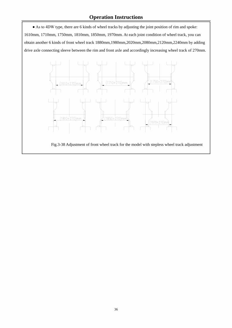
Operation Instructions
● As to 4DW type, there are 6 kinds of wheel tracks by adjusting the joint position of rim and spoke:
1610mm, 1710mm, 1750mm, 1810mm, 1850mm, 1970mm. At each joint condition of wheel track, you can
obtain another 6 kinds of front wheel track 1880mm,1980mm,2020mm,2080mm,2120mm,2240mm by adding
drive axle connecting sleeve between the rim and front axle and accordingly increasing wheel track of 270mm.
Fig.3-38 Adjustment of front wheel track for the model with stepless wheel track adjustment
36

Operation Instructions
3.11.3.2 Adjustment of rear wheel track (13.6-38 tire)
The wheel track is usually 1620mm. 7 kinds of wheel track position can be obtained by changing
connecting positions of the spoke, hub and rim. At each position, it is possible to obtain further 7 kinds of wheel
track adjustment range by adjusting the hub and the ”hub seat.
Fig. 3-39 Rear wheel track adjustment (13.6-38 tires) (unit: mm)
37

Operation Instructions
3.11.3.3 Adjustment of rear wheel track (16.9-34 tire)
The wheel track is usually 1600mm. 7 kinds of wheel track position can be obtained by changing
connecting positions of the spoke, hub and rim. At each position, it is possible to obtain further 7 kinds of wheel
track adjustment range by adjusting the hub and its pedestal.
Fig. 3-40 Rear wheel track adjustment (16.9-34 tires) (unit: mm)
Important: During adjusting the rear wheel track, be sure the tire side arrow or the tip of herringbone is
in line with tractor forward direction. Always ensure the 2 front wheels and rear wheels are symmetric to
tractor center line to prevent the machine from early wearing. During adjusting, firstly select proper rear
wheel track and then select front wheel. During adjustment, first select the most appropriate rear wheel
track, and then the front wheel track.
3.11.4 Adjustment of the toe-in of front wheel
38

Operation Instructions
Park the tractor at horizontal ground to enable the front wheel to
be at straight driving position, shown in Figure 3-39. By adjusting
length of the tie rod 2, obtain the toe-in value by subtracting B from
A. Pay attention that, after adjustment of the toe-in, the locknut 1 at
both ends of the tie rod should be tightened, respectively.
Fig. 3.-41 Adjustment of the toe-in of front wheel
1. Locknut; 2. Tie rod
3.12 Use and disassembling of tires
3.12.1 Use of tire
Tires are the main quick-wear parts of a tractor, so attention must be paid to the use and maintenance of
tires in order to prolong its service life as far as possible.
All tires have rated load values, overload will cause excessive deformation, the tire side will fracture easily
due to overbending, the tire fabrics and the buffer layers are also easily degummed so that the fabric layer will
loose until the tire is broken, and especially on the uneven pavement or due to obstacle impact, the tire is more
prone to rupture. The tire charging pressure must comply with the provision, and too high or too low pressure will affect the
service life. Too-low pressure may result in excessive deformation to quicken the tread wear, even make the
inner and cover tires quickly damaged and have the inflating valve cut off; and simultaneously have the running
resistance increased. If the front tire pressure is too low, the manipulation will be strenuous; if too high, the tire
fabrics will fracture due to excessive stretch, the tread will be worn quickly, and the body vibration will be
increased. In the field work, the tire pressure may be a little lower, but higher in long-term highway
transportation. The tire pressure should be checked with a barometer at the room temperature, so as to avoid
inaccurate measurement after the tire is heated due to work. Improper operation will also result in earlier wear
or damage of the tires. During running, crossing obstacles at a high speed, sudden brake or sharp turn should be
avoided. Driving on the gravel roads, the tire track slip should be avoided as much as possible.
During operation, do keep the tires away from oil, acid or alkali and other corrosive chemicals, and avoid
exposure to hot sun to prevent rubber from aging and deterioration. Front wheel alignment and front toe-in
must be frequently checked so as to avoid eccentric wear of the tires. If the tires have uneven wear, the left and
right tires may be exchanged.
Important: Charging pressure of front and rear tires of four-wheel drive type tractor should be same so
as to avoid abnormal wear of tires.
3.12.2 Tire disassembling
Tire disassembling
Do use special tools to dismount tires, but do not use sharp and hard tools (for example, screwdrivers) or
hammers to knock the tires disorderly, so as not to puncture the tire or damage the tire margins or rims.
39

Operation Instructions
When disassembling tires, do deflate firstly, press
the tire margins of the cover tire into the rim groove, then
use crowbars to force the tire margin near the inflating
valve on one side out of the rim, and then use two
crowbars alternatively to force thፉ� After the inner tube
is taken out, then do as above to force the tire margin on the other side out and then remove the cover tire.
Tire installation
When installing the tire, the rim should match
with tire. There should not be rug, serious distortion
and rust on the rim edge. When installing, first
clean the parts and then coat a thin layer of talc
between the inner tube and cover tires. Put the rim
flat, mount the cover tire, and force it into the rim.
Install inner tube (slightly underlay the outer tube), use lead wire to fix the core into the core hole of rim to
avoid it slipping. Use crowbar to lever the other side of outer tube into rim (you may apply greater force at
last phase and you can use hammer to gently hitting crowbar, as shown in figure.). Finally check whether the
inflating valve is positioned askew, and whether the tire edge fits the rim tightly. Moreover, check whether the
inner tube is broken and hammer the cover tire when inflating. It is better to bleed the air by half when inflated
to the specified pressure, and then inflate it once again, so as to have the inner tube normally expanded and
eliminate its wrinkles. If installing tires, please note the tread pattern direction. Otherwise it will affect the
gripping performance and resistance to corrosion. Moreover the mud is prone to be accumulated.
Warning: Never remove the bolts attaching tire/hub to wheel rim or attaching spoke to rim in
inflation state. Otherwise the bolts may rush out to hurt people.
3.13 Use of counterweight
3.13.1 Rear counterweight
When the tractor is working in the field, the counterweight
can be selected according to appropriate working type to
improve working performance of the tractor.
● 6 pieces of counterweights can be installed for large load
plowing area;
● 2 pieces of counterweights or no counterweight can be
installed for rotary tillage area;
● 4 pieces of counterweights can be installed for ordinary plowing area;
Fig.3-16 Tire installation
Fig.3-42 Tire disassembling
Fig. 3-44 Rear counterweight
40

Operation Instructions
Attention:
Before removing the rear wheels with rear counterweights from the tractor, it is necessary to remove
those rear counterweights from tires first to avoid the hazard of unstability.
3.13.2 Front counterweight
In order to balance the front and rear masses, it is necessary to
install front counterweight in front of tractor. When large load
plowing activities is carried out or a large-size seeding implement is
suspended, front counterweights with enough weight must be
installed to ensure that no rear-up occurs and ensure safe driving and
high performance. The tractor can be equipped with 11 pieces of
front counterweight of cast iron at bridge.
Warning: When the rear part of the tractor is equipped with a large-size implement, front counterweights with
enough weight must be equipped to ensure your safety; otherwise, it may result in roll-over risk!
3.14 Adjustment of Driver's seat
Fig. 3-45 Front counterweight
41

Operation Instructions
3.14.1 Front and rear adjustment of driver’ s seat
The seat can be adjusted forward and backward according to the
operator's height and by adjusting the seat forward/backward handle at
lower right side of the seat.
3.14.2 Front and rear adjustment of driver’ s seat
Adjust the operator's hand-wheel according to the operator's
height and weight.
Attention:
1. For safety, the seat should be adjusted when the tractor is at static to avoid potential hazard.
2. The seat rigidity should not be adjusted to excessive softness, especially on the irregular
pavement. This could prevent potential accidents occurring.
3.15 Tractor covering parts
It mainly including: hood, cab, mudguard, dashboard, floor and accessories etc.
3.15.1 Hood
The engine hood adopts elegant-appearance stream-line metal plate
structure. Pull the opening handle of hood lock located at the left side of
the lower-front wall of the hood to open the hood lock. Then gently lift
the hood up from the lower side and the hood automatically open under
the pushing force of the 2 air springs separateፉv If pulling the hood
from the lower point to a certain angle, the hood lock will automatically close and
Fig 3-46 Front and rear adjustment of driver’ s seat
1
Fig. 3-47 Rigidity adjustment of driver’ s seat
1
Fig. 3-48 Hood
42
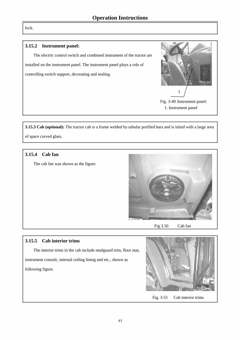
Operation Instructions
Fig. 3-49 Instrument panel: 1. Instrument panel
lock.
3.15.2 Instrument panel:
The electric control switch and combined instrument of the tractor are
installed on the instrument panel. The instrument panel plays a role of
controlling switch support, decorating and sealing.
3.15.3 Cab (optional): The tractor cab is a frame welded by tubular profiled bars and is inlaid with a large area
of space curved glass.
3.15.4 Cab fan
The cab fan was shown as the figure.
Fig.3.50 Cab fan
3.15.5 Cab interior trims
The interior trims in the cab include mudguard trim, floor mat,
instrument console, internal ceiling lining and etc., shown as
following figure.
Fig. 3-51 Cab interior trims
1
43

Operation Instructions
3.15.6 Doors
The tractor doors adopt profiled door frame, inlaid with
monoblock curve glass. Integrating with the streamline cab not
only shows the spacious and comfortable driving room, but
also greatly improves the elegance appearance of the tractor.
Door opening steps are as follows: clockwise rotate the door
key by 90°, after taking out the key, grasp the door handle with
thumb pushing the pressing piece 2, meanwhile
pull the handle outward to open the door. Lock
the door in reverse order of the above mentioned.
3.15.7 Left and right side windows
All-glass structure is adopted. In the case side window open, lift lock-up handle and push the window
outward simultaneously until it is stuck and then lift the lock-up handle gently so as to
open the side window and limit to a certain place. Besides, the max. side window
distance is the effective length for the lock-up handle.
Fig. 3-53 Left and right side windows
1. Lock-up handle
3.15.8 Rear window
Tractor rear window is semi-automatic. It can open upwards to two positions:
normal and maximum.
● Normal state: Rotate handle, Push handle outward when projection in the front of
the handle slips off its groove until the projection in the rear of the handle reaches the
groove and then rotate the handle once again to slip the rear projection into the groove so
as to keep the rear window open and maintain a certain opening angle.
In its closing, operate in the reverse order.
● Max. state: Place the handle. Push handle outward when projection in the front of
the handle slips off its groove until the pulling force from air spring is overcome. Then,
air spring is changed from “pulling” into outward “pushing”. Then, the rear window
reaches its opening position automatically. In the case of its closing, pull the handle
inward to overcome “pushing” force from air spring and then air spring is changed
Fig.3-52 Cab door lock 1. Door key 2. Door lock 3. Push rod
4. Locking plate 5. Unlocking handle 6. Door handle
Fig. 3-54 Rear window
44

Operation Instructions from outward “pushing” into inward “pulling” and then the rear window closes automatically. Rotate the handle
once again to slip the front projection Into its groove for its lock-up state.
3.15.9 Sun roof
The sun roof adopts glass reinforced plastic structure. In the case of
sun roof open, hold the handle and press the sun roof lock with your
thumb simultaneously and then the lock will be unlocked automatically.
Push the sun roof outward gently and it opens automatically with the
effect of left and right air springs. In its closing, operate in the reverse
order. Fig. 3-55 Sun roof
3.15.10 Cab HVAC (heating ventilation and air conditioning) (optional)
The dual-purpose air conditioner possesses 2 air outlets in
the cab. You can rotate cover plates for these air outlets to adjust
air volume and blowing direction; At the leftmost side of the
HVAC is its control panel which possesses control modes as
follows:
3.15.10.1 Separate ventilation control
● Turn off water inlet and outlet switch for the air heater on
the engine;
● Rotate air speed switch in the middle of the control panel to adjust air speed so as to obtain natural wind.
3.15.10.2 Air conditioner control
● Turn off water inlet and outlet switch for the air heater on the
engine;
●Turn on the compressor switch on the leftmost of control panel
to make the compressor filled with refrigerant begin to work. The cold
air could be blown into cab to reduce the temperature.
● Rotate HVAC temperature control switch at the right side of the
control panel to adjust the interior temperature
● Rotate air speed switch in the middle of the control panel to
adjust the air speed..
Fig. 3-56 Air conditioner
Fig. 3-57 HVAC control panel
45

Operation Instructions
3.15.10.3 Air heater control
● Turn off compressor switch at the leftmost side of the control panel
● Turn on water inlet and outlet switch of the air heater on the engine and warm water starts to its
circulation in the air heater. Heated air can be provided to the interior of the cab to increase interior
temperature.
● Rotate air speed switch in the middle of the control panel to adjust the air speed
3.16 Usage of tractor operation device
This tractor series is mainly composed of the following working devices:( optional for some devices)
● Hydraulic lifter: the force-position combined adjustment shall be preferred when plowing operation is
added so as to ensure operation effect;
● Simply hydraulic output: mainly used for hydraulic trailer etc.
● Hydraulic output device: used for hydraulic reversible plough, hydraulic harrow etc.
● Suspension mechanism: mainly used for hooking agricultural implement etc.
● PTO device: Mainly used for power needed agricultural implement etc.
● Pendulum towing device: mainly used for harrow, mower, tractor-powered seeder etc.
● Towing rack: mainly used for signal-axle trailer and double-axle trailer etc.
Select farm implements for the tractor
Important: Select agricultural implements for the tractor Overly high power might result in damage of
agricultural implements, and oversize agricultural implements may lead to damage of the tractor. (Before
installation the agricultural implements, refer to your agricultural implement manual for the agricultural
3.15.11 Safety rack
Tractor safety rack is a frame welded by rectangular tubes and it can be overturned and folded.
Safety rack extension position schematic diagram Safety rack nfoldment position schematic diagram
Fig. 3-58 Safety frame
46
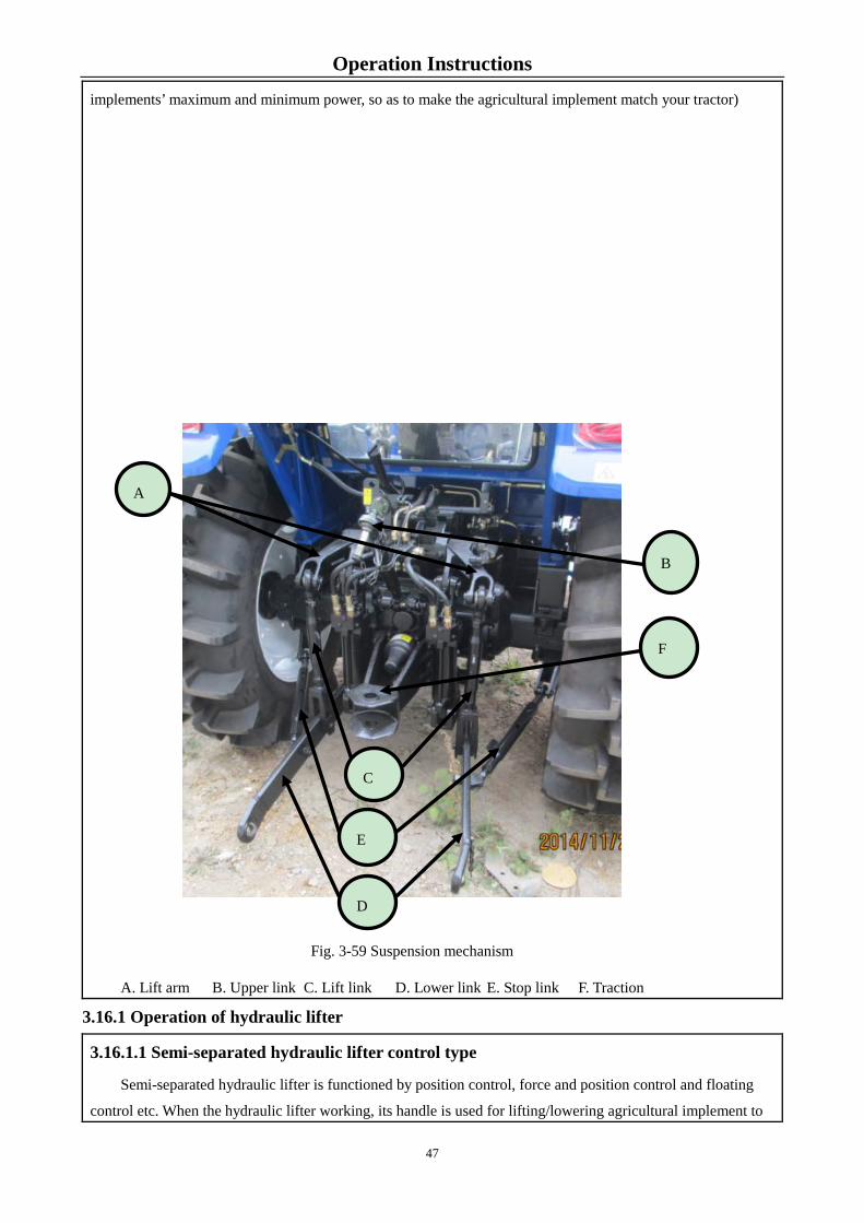
Operation Instructions
implements’ maximum and minimum power, so as to make the agricultural implement match your tractor)
A. Lift arm B. Upper link C. Lift link D. Lower link E. Stop link F. Traction
3.16.1 Operation of hydraulic lifter
3.16.1.1 Semi-separated hydraulic lifter control type
Semi-separated hydraulic lifter is functioned by position control, force and position control and floating
control etc. When the hydraulic lifter working, its handle is used for lifting/lowering agricultural implement to
Fig. 3-59 Suspension mechanism
B
F
C
E
D
A
47
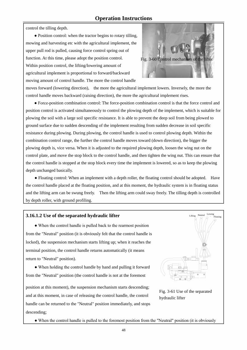
Operation Instructions control the tilling depth.
● Position control: when the tractor begins to rotary tilling,
mowing and harvesting etc with the agricultural implement, the
upper pull rod is pulled, causing force control spring out of
function. At this time, please adopt the position control.
Within position control, the lifting/lowering amount of
agricultural implement is proportional to forward/backward
moving amount of control handle. The more the control handle
moves forward (lowering direction), the more the agricultural implement lowers. Inversely, the more the
control handle moves backward (raising direction), the more the agricultural implement rises.
● Force-position combination control: The force-position combination control is that the force control and
position control is activated simultaneously to control the plowing depth of the implement, which is suitable for
plowing the soil with a large soil specific resistance. It is able to prevent the deep soil from being plowed to
ground surface due to sudden descending of the implement resulting from sudden decrease in soil specific
resistance during plowing. During plowing, the control handle is used to control plowing depth. Within the
combination control range, the further the control handle moves toward (down direction), the bigger the
plowing depth is, vice versa. When it is adjusted to the required plowing depth, loosen the wing nut on the
control plate, and move the stop block to the control handle, and then tighten the wing nut. This can ensure that
the control handle is stopped at the stop block every time the implement is lowered, so as to keep the plowing
depth unchanged basically.
● Floating control: When an implement with a depth roller, the floating control should be adopted. Have
the control handle placed at the floating position, and at this moment, the hydraulic system is in floating status
and the lifting arm can be swung freely. Then the lifting arm could sway freely. The tilling depth is controlled
by depth roller, with ground profiling.
3.16.1.2 Use of the separated hydraulic lifter
● When the control handle is pulled back to the rearmost position
from the "Neutral" position (it is obviously felt that the control handle is
locked), the suspension mechanism starts lifting up; when it reaches the
terminal position, the control handle returns automatically (it means
return to "Neutral" position).
● When holding the control handle by hand and pulling it forward
from the "Neutral" position (the control handle is not at the foremost
position at this moment), the suspension mechanism starts descending;
and at this moment, in case of releasing the control handle, the control
handle can be returned to the "Neutral" position immediately, and stops
descending;
● When the control handle is pulled to the foremost position from the "Neutral" position (it is obviously
Fig. 3-60 Control mechanism of the lifter
Fig. 3-61 Use of the separated hydraulic lifter
Neutral Floating Lifting
Lowing
48

Operation Instructions
felt that the control handle is positioned), the suspension mechanism is at "Floating" status after being
descended to the terminal position.
3.16.1.3 Control of the implement
descending speed (Semi-separated type
hydraulic lifter)
To adjust the descending speed of the
implement and lock the implement at required
position, a descending speed control hand-wheel
“A” is provided (See Figure 3-58). When
turning the hand-wheel in counterclockwise
direction,the descending speed of the implement
slows; when turning the hand-wheel in
clockwise direction, the descending speed of the
implement increases. During use, an appropriate
descending speed of the implement is selected
according to quality and size of the implement and ground hardness, so as to avoid damage to the implement
resulted from too fast descending speed.
When the tractor with an implement is transported, the implement should be lifted to the highest position,
and then the descending speed control hand-wheel is screwed out in counterclockwise direction to enable the
implement not to descend, and at this moment, the implement is locked at the highest position to activate the
hydraulic lock to safely transport the tractor with the implement.
Note: The lifter and simple hydraulic output cannot be used simultaneously. When the simple hydraulic
output is not required, dismantle the hydraulic output pipeline, re-tighten the sleeve and hollow bolt onto
the cylinder head, and turn the descending speed control hand-wheel in counterclockwise direction, open
the oil line to the lifter cylinder, so that the lifter can work again.
3.16.2 Simple hydraulic output (Semi-separated type hydraulic lifter)
Use of descending speed control hand-wheel
Baffle
Fig. 3-62 Use of descending speed control
49

Operation Instructions
When the hydraulic output is required, the following
steps should be carried out:
Push the control handle to the down
position to lower the suspension lever part at the
lowest position;
Thoroughly tighten the descending speed
control hand-wheel "A" in clockwise direction to
close the oil line to the lifter cylinder.
Unscrew the hollow bolt "B" of the
hydraulic output from the cylinder head, remove the
sleeve, connect the high-pressure oil pipe, set the control handle to "Up" position, so that the pressure oil can
enter the hydraulic output device for hydraulic output. If the oil is returned via the hydraulic output device,
only the control handle can be set to Down position.
Important: When an implement with a power take-off is required, it is required that the implement be
lifted above the ground and the lifting height having no influence on steering of the tractor in the field be
guaranteed, for the purpose of preventing excessive lifting height of the implement resulting in damage to
the drive shaft that is connected from the PTO shaft to the implement.
3.16.3 Operation and use of hydraulic output device
The tractor can be installed with 1 or 2 optional spool
valve type hydraulic output multi-way valve as required. Two
valves are controlled by C and D operating handle, respectively,
so as to control two double-action oil cylinder on the
implement. Use 4 M10 bolts to fix the multi-way valve onto
the multi-way valve fixing plate. The fixing plate is connected
with the housing of the rear axle half shaft. The oil inlet and oil
return port of the multi-way valve are connected with the
gear pump and lifter, respectively, and the oil outlet is
connected to the oil inlet of the distributor. Each control
valve has female connection A1 and B1 and A2 and B2 of 2
M22×1.5 quick-change connectors (as shown in Figure
3-60). When the connection is not used, have it sealed with a sealing cover. During use, connect the spare
male connection (placed in the spare parts box) to the oil inlet and outlet of the hydraulic implement, and then
connect the female connection of the quick-change connector. The control handle "C" is used to control the
first hydraulic output A1 and B1, and the control handle "D" is used to control the second hydraulic output A2
and B2. If a single-action cylinder is connected, the oil pipe of the oil cylinder is connected the first output A1
or second output A2. Operating the control handle "C" and "D" upward and downward, and operating the
Fig. 3-63 Simple hydraulic output
Fig. 3-64 Hydraulic output device 1. Quick-change connector 2. Control-handle 3.Multi-way valve pipeline 4 Multi-way valve assembly 5. Multi-way valve fixing plate 6. Oil return pipe assembly.
50

Operation Instructions
single-action or double-action oil cylinder can complete corresponding action. Two hydraulic output valves
can realize single-action hydraulic output or double-action hydraulic
output by screwing in or screwing out the single- and double-action
screw "E" on the multi-way valve (Shown as Figure 3-61). Unscrew
the screw "E" in counterclockwise direction to realize single-action
hydraulic output. On contrary, screwing in the screw "E" is able to
realize double-action hydraulic output.
When using quick-change coupler, please firstly complete the
following work, and then insert the positive pole of agricultural
implement into negative pole.
● Stop the engine
● Lower the hitched agriculture tool
● Forward or backward moving the hydraulic output control handle could eliminate the pressure in the
hydraulic quick-change connector block
● Remove the sealing cover on the quick-change negative connector and clean the quick-change
connector.
Important:
1. When not in use of quick-change coupler, its hole should be covered by dust cover.
2. After hydraulically output device is operated over, its operating handle should be set to neutral
position, otherwise, it may cause hydraulic system overheat;
Important:
1. If the tractor with agricultural implement transferring for a long distance, please shorten the
upper pull rod and adjust the limit rod to avoid swinging of agricultural implement. Whilst tighten the
nuts from the upper pull rod and limit rod to avoid damaging machine caused by excessive swing.
2. Please lift the agriculture implement to steer the tractor if needed at the field edge. Doing so could
avoid damaging machine. You can lower the agricultural implement after straight traveling.
3.16.4 Use of suspension mechanism
Fig. 3-65 Multi-way valve assembly 1. Single/double action switching screw “E”
51

Operation Instructions
Lovol Oubao TD Series Tractors adopt a rear
three-point suspension device to couple the
implement. The maximum lifting travel of the
lower draw bar (factory status: the lifting lever is
connected with the "B" hole) is 635mm for the
semi-split type, and 66ፉ¤
3.16.4.1 Before connecting, please check the
swing type towing rod or other possible objects
for interference. Move it forward or remove it as
needed.
3.16.4.2 The tractor runs to the agricultural
direction to align with the towing point. Place
the main gear lever to neutral position, depress the brake pedal and
simultaneously lift the hand brake.
3.16.4.3 Place the hand accelerator to the lowest position to idle for 1-2min, then shut down engine to connect
the agricultural implement.
3.16.4.4 Lower tied rod connection
The lower tie rod and the lifting lever have two connecting holes, i.e. front hole "C" and middle hole "B".
During normal operation, the middle hole "B" is connected usually, but when long-distance transportation of
the implement to be suspended is required, the front hole "C" should be connected.
The hole connecting the lower draw bar to the limit rod is the rear hole "A".
3.16.4.5 Connection of lifting rod
Generally, length of the lifting rod should be adjusted to its intermediate length. Generally, length of the
lifting rod should be adjusted to its intermediate length. The left and right lifting rods can be adjusted by turning
the guide pipe weld unit of the middle lifting rod. Adjustment of the lifting rod mainly refers to adjustment of
horizontal position of the implement. The following instructions are given by taking the plough adjustment as
an example:
Regulation of left level and right level of plough frame: Regulate length of right lifting lever to make
plough frame keep level, so as to guarantee the consistent tilling depth. Unscrew the nuts at both ends of
spiral pipe, rotate the regulation plate of right lifting lever clockwise, extend the right lifting lever, make
the tilling depth of the first bottom plough become deeper, and then shorten the lifting lever by rotating
regulation plate counterclockwise. Generally, it is not necessary to regulate the left lifting lever, and only
when the regulation amount of right lifting lever is not enough, can the left length be regulated to meet
requirements. After the regulation is completed, screw down nuts at both ends of spiral pipe of lifting
lever, so as to avoid position change during the using.
Fig. 3-66 Lower tied
A B C
52

Operation Instructions
Adjustment of front and rear level: adjust the upper draw bar of the suspension mechanism, and when front
furrow depth or rear plough heel leaves the bottom of ditch, extend the upper draw bar, and for rear furrow
depth, shorten the upper draw bar to keepፉl
Adjustment of tilling width: the adjustment of tilling width is achieved mainly by adjusting the tilling
width adjuster of plough. Front and rear relative positions of left and right lower suspension points can be
changed by adjusting the tilling width adjuster. If the right lower suspension point is moved forward, the
tilling width will be increased; otherwise, the tilling width will be reduced. The normal position of plough
frame can be guaranteed by adjusting the tilling width adjuster to avoid any repeated plough or missed
plough.
A-lifting rod adjusting plate
B-Locknut
C-lifting rod screw tube
3.16.4.6 Upper draw bar connection
The upper link is connected with the support via 3 holes. An appropriate position is selected according to
the post height of the implement. Generally, when the post height is equal to or less than 510mm, select the
lower hole; when the post is between 510~610mm, select the middle hole; when the post height is equal to or
more than 610mm, select the upper hole. Adjustment can also be conducted according to actual conditions.
Adjustment of the upper link is mainly carried out to adjust the longitudinal and horizontal position of the
implement, and adjust consistency in the front and rear plowing depth.
A
B
C
Fig. 3-67 Regulation of
53

Operation Instructions
3.16.4.7 Adjustment of limit rod
The limit rod is mainly used to limit lateral
oscillation of the implement (i.e. the lower tie rod).
Insert the pin into the long hole of the limit sleeve so that
the limit rod can be moved with a certain range; when the
pin is inserted into the front hole of the limit sleeve, the
limit rod can be kept standstill. Turning the threaded
limit sleeve can adjust length of the limit rod. The rear
hole is used to receive the pin when adjusting length of
the limit rod.
The movement of the limit rod is selected according to
working type of the implement. The limit rod should be moved within a certain range when the tractor with a
plough or harrow is working, so that the tractor has excellent operating performance. The limit rod should be
fixed when the tractor with a rotary plough or mower is working.
Fig. 3-68 Adjustment of
B
M
A
C
B
Fig. 3-69 Adjustment of limit rod A-Limit rod extension guide lever B-Limit rod pin
C-Limit rod sleeve
54

Operation Instructions
Fig. 3-70 Diagram for Movement of Suspension Mechanism for the Vehicle Model
with a Semi-separated Type Lifter
55

Operation Instructions
Fig. 3-71 Diagram for Movement of Suspension Mechanism for the Vehicle Model
with a Semi-separated Type Lifter
1. Driving wheel center 2. Lower hinging point 3. Connecting point of lift shaft 4. Supporting point of oil cylinder 5. Upper hinging point
56
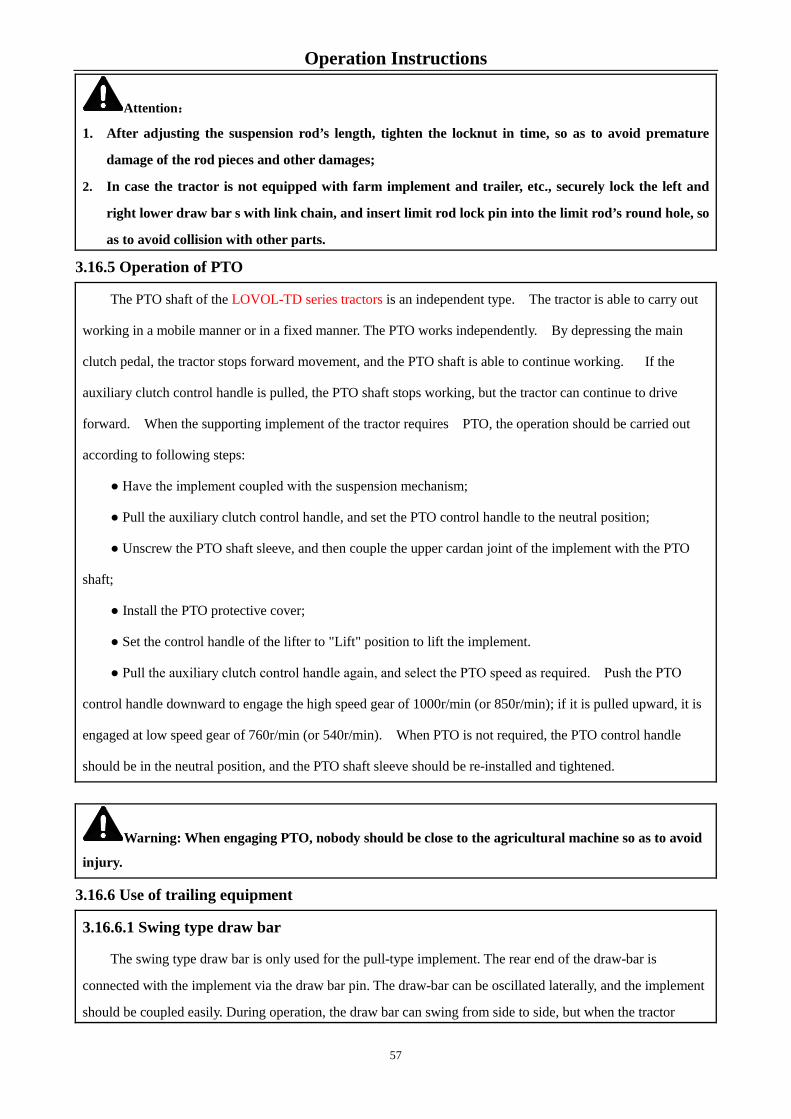
Operation Instructions
Attention:
1. After adjusting the suspension rod’s length, tighten the locknut in time, so as to avoid premature
damage of the rod pieces and other damages;
2. In case the tractor is not equipped with farm implement and trailer, etc., securely lock the left and
right lower draw bar s with link chain, and insert limit rod lock pin into the limit rod’s round hole, so
as to avoid collision with other parts.
3.16.5 Operation of PTO
The PTO shaft of the LOVOL-TD series tractors is an independent type. The tractor is able to carry out
working in a mobile manner or in a fixed manner. The PTO works independently. By depressing the main
clutch pedal, the tractor stops forward movement, and the PTO shaft is able to continue working. If the
auxiliary clutch control handle is pulled, the PTO shaft stops working, but the tractor can continue to drive
forward. When the supporting implement of the tractor requires PTO, the operation should be carried out
according to following steps:
● Have the implement coupled with the suspension mechanism;
● Pull the auxiliary clutch control handle, and set the PTO control handle to the neutral position;
● Unscrew the PTO shaft sleeve, and then couple the upper cardan joint of the implement with the PTO
shaft;
● Install the PTO protective cover;
● Set the control handle of the lifter to "Lift" position to lift the implement.
● Pull the auxiliary clutch control handle again, and select the PTO speed as required. Push the PTO
control handle downward to engage the high speed gear of 1000r/min (or 850r/min); if it is pulled upward, it is
engaged at low speed gear of 760r/min (or 540r/min). When PTO is not required, the PTO control handle
should be in the neutral position, and the PTO shaft sleeve should be re-installed and tightened.
Warning: When engaging PTO, nobody should be close to the agricultural machine so as to avoid
injury.
3.16.6 Use of trailing equipment
3.16.6.1 Swing type draw bar
The swing type draw bar is only used for the pull-type implement. The rear end of the draw-bar is
connected with the implement via the draw bar pin. The draw-bar can be oscillated laterally, and the implement
should be coupled easily. During operation, the draw bar can swing from side to side, but when the tractor
57

Operation Instructions
draws the implement in reverse direction, the 2 dowel
pins must be inserted into the hole of the drawplate to
keep the drawbar standstill.
Turning the draw bar over can change height of the
towing point to obtain a towing height suitable for the
supporting implement.
Fig. 3-72 Use of draw bar (delivery status of the complete vehicle)
A-Swing Lever B-Locating Pin C-Traction Pin
3.16.6.2 Towing frame
The towing frame is suitable for various
types of trailers, and cannot be installed
together with the swing draw bar.
A-Towing Frame B-Towing Pin
A
B
C
Figure 3-73 Towing
A
B
The traction lever swings to left (with swing angle of 15°).
The traction lever swings to right (with swing angle of 15°)
58

Operation Instructions
Warning: 1. Do not exceed the limit load during towing or with trailer. Otherwise the machine life will be
shortened or even serious accidents may occur.
2. When braking, apply trailer brake before tractor brake. Otherwise rollover accident may occur.
3.16.7 Operation of the trailer brake system
Fig 3-74 Trailer brake system
The trailer air brake system is a "shut-off" control system. It is required that its supporting trailer must be
equipped with a complete "shut-off" control device. For the trailer that is only equipped with a "air supply"
control brake device having a brake air chamber and controller, the "air supply" control system must be
modified with a "shut off" control system.
● If the tractor transporting with trailer, please take note the air pressure indicator lamp. The air pressure in
the air reservoir should not be less than 0.45MPa. Otherwise, you are allowed to drive the tractor only raising
the air pressure to set value.
● Generally, the balance pressure in the air reservoir should not be less than 0.70MPa. When the engine is
stopped, if the barometer reading drops rapidly, it indicates that there is an air leak. Check and remove it in
time.
1 Air compressor 2. Air receiver inlet pipe 2. Push rod 4. Air delivery pipe 5. Tee union 6. Safety valve assembly 7. Shut-off brake valve 8. Air receiver 9. Plug 10. Brake valve air outlet 11. Quick coupler
59
Operation Instructions
● The opening pressure of air reservoir safety valve is (0.75~0.8) MPa, and if the air pressure alarm alarms
when using, make adjustment timely.
●During use, if the pressure of tractor air reservoir is normal while the pressure of trailer air reservoir is
lower (represented by that effective braking of trailer cannot be guaranteed), only adjust the adjusting screw on
the left of the brake valve.
● If the air pressure is always within (0.75~0.8)MPa or more, it indicates the relief valve will not work.
Please timely clean or replace the relief valve.
● If the tractor transporting with trailer, please check the whole braking system to ensure the trailer
braking is synchronizing with tractor braking or is slightly in advance rather than lag behind. You can adjust
the adjusting screw on the brake valve to satisfy the requirements if necessary. If necessary, adjust the adjusting
screw of brake valve to meet the above requirements.
Warning: 1. If the trailer braking lags behind the tractor braking, rollover may occur.
2. The two adjusting screws of brake valve pull rod are already adjusted on the exclusive test bed
when delivery, and coated with red mark. Do not screw it at will to avoid invalid braking.
3. After each 50h, open the drain valve to drain the deposited water in the reservoir to ensure
braking system normal work.
3.16.8 Use and adjustment of electrical system
The electric system of LOVOL-TD Series tractors adopts a double-wire system at voltage of 12V, with
negative pole of the silicon rectification generator being bonded. It is composed of engine startup equipment
and lighting signal devices. The engine startup equipment include starter motor and silicon rectification
generator. For details about use and maintenance of the equipment mentioned above, see the instructions for
engine operation and maintenance. The lighting and signal unit is composed of front combination lamp,
reversing lamp, cab ceiling lamp, handrail lamp (steering and position), rear tail-lamp (steering, position and
braking), and central electric box.
The diagram for electric circuit of LOVOL-TD Series tractors is shown in Figure 3-69. For details on
electric circuit number, nominal sectional area and conductor color, see Table 3-2.
Table 3-2 LOVOL TD series tractor wire No., nominal sectional area and wire color
Wire NO.
Nominal cross section
Wire Color
Wire numb
er
Nominal Cross
section
Wire Color
Wire numb
er
Nominal Cross
section
Wire Color
Wire numb
er
Nominal
Cross section
Wire Color
60

Operation Instructions
1 4.0 Red (R) 13 0.75 Green Blue
(GL) 26 0.75 Orange (O) 39 4.0
Brown (Br)
1b 2.5 Red(R) 14 1.0 White red
(WR) 27 0.75
Green black (GB)
40 0.75 Gray
2 1.5 Pink (V) 15 1.5 Blue red
(LR) 28 0.75
Orange blue (OL)
42 2.5 Black (B)
3 4.0 Red white
(RW) 16 1.0
Red white (RW)
29 0.75 Green Gray
(GS) 50 1.0 Pink (V)
4 1.5 Yellow (Y) 17 0.75 Pink Green
(VG) 30 0.75
Brown Yellow (BrY)
51 1.0 Pink White
(VR)
5 1.0 Green (G) 18 0.75 Brown
(Br) 31 0.75 White (W) 53 0.75
Red Brown (RBr)
6 1.5 Blue (L) 19 0.75 Light Blue
(LU) 32 0.75
Brown white (BrW)
54 0.75 Blue Green
(LG)
7 1.0 Yellow Black
(YB) 20 0.75
Red white (RW)
33 0.75 Red Green
(RG) 55 0.75
Red Gray (RS)
8 0.75 Gray White
(SW) 21 0.75
Blue Black (LB)
34 1.0 White Blue
(WL) 56 0.75
Light Green (LuG)
9 1.0 Red Blue
(RL) 22 0.75
Red Black (RB)
35 0.75 Green Red
(GR) 57 0.75
Gray Black (SB)
10 1.5 Yellow Red
(YR) 23 1.0 Purple (P) 36 0.75
Purple Black (PB)
10a 0.75 Yellow Red
(YR)
11 1.0 Red Yellow
(RY) 24 1.5
Green White (GW)
37 1.0 Purple
Yellow (PY) 42a 0.75
Black (B)
12 1.0 Yellow Blue
(YL) 25 0.75
Brown Red (BrR)
38 0.75 Brown Green
(BrG)
Rear lamp and rear tail lamp
Position drawing for rear lamp and real tail lamp
(steering, position, braking).
Fig.3-75 Rear lamp and rear tail lamp
61

Operation Instructions
Plug socket of rear trailer
The rear trailer connector socket is wired at the position shown
as Figure 3-67. The wiring instructions are as follows:
Fig. 3-76 Trailer socket
Roof lamp
There are four cab roof lamps, which are positioned
at front upper part and rear upper part of the cab. The
front roof lamps of the cab are shown as the right figure.
The roof lamp body can be turned to right/left as
required during working, so as to meet requirement for
change in light direction.
Fig. 3-77 Roof lamp
Central electrical control box
A main power supply relay, electronic flash indicator, light relay and other electric circuit control
components are set in the central electric box. And, there are 15-way fuses. Working current and electric
apparatuses protected at each gear are shown in Table 3-3. When the electric components are disconnected,
first inspect the fuse in the electric box; in case that the fuse is damaged, remove a spare fuse with same current
rating for displacing the damaged one immediately, so as to ensure no damage to the electric components.
Contact point 1: connect with the left
steering lamp
Contact point 2: naught
Contact point 3: ground wire
Contact point 4: connect with the right
steering lamp
Contact point 5: connect with right
62

Operation Instructions
1
Table 3-3 Working current of each way and protected electrical elements
Unit: A
Range
of the
fuse box
I II III IV V VI VII VIII IX
Rated
working
current
10 10 20 10 10 20 5 20 15
Protecte
d
electric
apparatu
s
Brake
lamp
and horn
Steering
lamp
alarm
Wiper
and air
conditio
ner
Dipped
beam of
headlam
p
Far beam
of
headlam
p
Accesso
ries
power
supply
Position
lamp
Roof
lamp
Light
relay
Fig. 3-78 Central electrical control box
63

Operation Instructions
Fig.3-77 electrical schematic diagram
64
Operating Instructions 3.17 Running-in of tractor
A series of work called running-in should be done to a tractor before use, i.e., make it run under specified
lubrication, speed, and load conditions for some time, and at the meanwhile conduct necessary inspection,
adjustment and maintenance to normalize.
3.17.1 Preparations before running-in
● During running-in period, perform technical maintenance on the tractor every shift and every 50 hours.
(See the Maintenance Instructions in the Section 5 of this manual.)
● Check and tighten the tractor external bolts, nuts and screws.
● Add lubricating grease in the oil cups of the front hub, front drive axle pin and the water pump shaft.
Check the oil levels of engine oil pan, transmission and lifter, the central and final drive of the front drive axle.
Fill as required.
● Fill fuel oil and coolant conformed to label.
● Check whether tire pressure is normal.
● Check whether electrical circuit is normal and reliable.
● Each control handle is placed at neutral position.
3.17.2 Engine idle running
Keep the engine at idle running for 15 minutes. After its startup, keep the engine running at low-speed
(Low accelerator), medium-speed (Medium accelerator), and finally high-speed (High accelerator), each for
5min (minutes) in the order as specified in "Operation and Maintenance Instructions for Diesel Engine".
In the process of engine's idle running, check carefully the working conditions of engine, air compressor
and hydraulic pump to observe whether there are any anomalies and sound, leakages of water, oil and air.
Inspect if the instrument works properly. In case of any off-normal occurrence, immediately shut it down and
start running-in after troubleshooting.
Conduct the following running-in after ensuring that the engine could work perfectly and normally.
3.17.3 Power output shaft running-in with no load
Place the engine accelerator control lever in the medium accelerator position to enable the engine running
at medium speed. Keep the power output shafts rotate at low speed and high-speed respectively, each for
5minutes, and check for anomalies. After running-in, make sure the PTO shaft is in neutral position.
65

Operating Instructions 3.17.4 Hydraulic system running-in
Start the engine to operate with the accelerator being placed on the accelerator position, maneuver
dispenser handle to lift and drop suspension mechanism several times to observe whether there is any anomaly.
Then hang a mass of about 800kg (kg) weight or mating farming tools of the same weight on the suspension
mechanism, let the engine operate in the large accelerator position, manipulate dispenser handle to make the
suspension mechanism rise and fall at whole stroke not less than 20 times. Check whether the hydraulic
suspension mechanism can be fixed at the highest position or desired position, the lifting time and whether
there is any leakage.
Keep the tractor stand still and the engine operate at low, medium and high-speed, steer the steering wheel
smoothly to the left and right for 10 times respectively, and observe the follow-up conditions of the tractor!/s
front wheel steering, whether the sound is normal, and the steering wheel manipulation is light and smooth.
If any fault is found in running-in, a timely analysis of the causes should be made and ruled out. 3.17.5 Tractor Running without Load and Running-in with Load
After idling running-in of the engine and running-in of the PTO shaft and hydraulic system, the complete
machine can be subject to running-in only after confirming that technical status of the tractor is fully normal.
The running-in sequence and time is iፉ² When being idle running-in, exercise turning and use unilateral brake
properly at low speed, and test emergency braking at high speed.
Only when the technical state of the tractor is completely normal after the idle running-in, can load
running-in be carried out with load increasing from small to large, gear position changing from low to high. The
tractor having an optional creeper gear can be engaged in the creeper gear for running-in operation. When the
four-wheel drive tractor can be engaged in the I~IV gear for run-in operation, the front drive axle can be
engaged; when the tractor is engagፉፉ Attention should be paid in the running-in process to:
● Observe whether the readings of electrical equipment and various instruments are normal
● Whether the engine is running properly.
● Whether clutch engagement is smooth and separation is complete.
● Whether gearbox shifting is light and flexible, whether there is any random gear change or spontaneous
out-of-gear.
● Whether the brake works reliably.
● Whether engagement and separation of the differential locks is reliable.
● Whether the engagement and separation of front drive axle is reliable.
Faults should be excluded when found before running-in continues.
66

Operating Instructions 3.17.6 Technical maintenance after running-in
After running in the tractor, there will be metal filing or dirt in the lubricating oil of the drive system,
lubricating system and hydraulic system. Therefore, be sure to drain the oil in such systems and pour new oil in
them. Perform the necessary technical maintenance on the tractor before putting it into normal operation.
The technical maintenance after running-in is as follows:
● Discharge the engine oil in the engine oil pan and the steering system while hot after the shutdown,
clean the oil pan, oil filter screen, air filter and filter screen in the steering tank, replace the filter element of
diesel filter and oil filter, and then fill in new lubricating oil according to the technical requirements.
● Drain the oil in the drive system, hydraulic system, steering system and front drive axle when it is hot,
and add some light diesel oil or kerosene properly. Without starting the engine, drag the tractor slowly forward
or backward for about 3 min (minutes) or with the front and rear wheels of the tractor off the ground, turn the
front and rear tires in two directions for about 3 min (minutes), and then drain the cleaning fluid immediately.
Meanwhile, remove the suction filter of the lifter and clean or replace it. Re-install the suction filter, and then
add new oil to the power train system, hydraulic system, steering system and the front drive axle as required.
● When conducting first maintenance of the hydraulic system with an independent oil supply, its hydraulic
oil may not be changed, but only cleaning or replacing the filter element is required.
● Maintain the diesel engine according to "Operation and Maintenance Instructions for Diesel Engines".
● Drain the coolant. Clean the engine cooling system with fresh water, and then add new coolant.
● Check the toe-in of front wheels, and free travels of the clutch and brake. If necessary, adjust them.
● Check and tighten all external bolts, nuts and screws.
● Fill lubricating grease to each tractor parts according to Maintenance and Service Schedule.
Important:
1. The newly-made or overhauled tractors can only be put into normal use after the running-in;
Otherwise, the service life of the tractor will be shortened.
2. The driver must first learn and be familiar with the manipulation and use of tractor prior to the
running in.
Table 3-4 LOVOL TD series tractor running-in specification [8F+4R or 16F+8R(creeper gear optional)]
Traction Load (kN) 0 3~4 7~8 10.5~11.5
Equivalent operating items
Empty
Driving
Transportation with 4t goods in trailer
Equipped with plough, the sand soil with specific resistance of 30 ~ 35kPa, tilling depth of 18~20cm.
Equipped with plough, the clayed soil with specific resistance of 45 ~ 50kPa, tilling depth of 20cm.
Throttle opening 3/4 3/4 Fully-open Fully-open
67

Operating Instructions
Direction
Creeper gear
Auxiliary
gearshift
Main gearshift
Forward gear
Low speed gear
Low speed gear
1 0.5
2
3
4
High speed gear
1
2 0.5
3
4
High speed gear
Low speed gear
1 0.5
2 0.5
3 0.5 2 10 8
4 0.5 2 11 15
High speed gear
1 0.5 4 11 15
2 0.5 4 4
3 0.5 4
4 0.5 3
Reverse
gear
Low speed gear
Reverse gear
1
2
3
4
High speed gear
Reverse gear
1 0.5
2 0.5
3 0.5
4 0.5
Total hour numbers h 7 19 36 38
Table3-5 Lovol-TD series tractor running-in specification(16F+8R shuttle type gear shift)
Traction Load (kN) 0 3~4 7~8 10.5~11.5
Equivalent operating items
Empty
Driving
Transportation with 4t goods in trailer
Equipped with plough, the sand soil with specific resistance of 30 ~ 35kPa, tilling depth of 18~20cm.
Equipped with plough, the clayed soil with specific resistance of 45 ~ 50kPa, tilling depth of 20cm.
Throttle opening 3/4 3/4 Fully-open Fully-open
Direction
Creeper gear
Auxiliary
gearshift
Main gearshift
68

Operating Instructions Traction Load (kN) 0 3~4 7~8 10.5~11.5
Equivalent operating items
Empty
Driving
Transportation with 4t goods in trailer
Equipped with plough, the sand soil with specific resistance of 30 ~ 35kPa, tilling depth of 18~20cm.
Equipped with plough, the clayed soil with specific resistance of 45 ~ 50kPa, tilling depth of 20cm.
Throttle opening 3/4 3/4 Fully-open Fully-open
Direction
Creeper gear
Auxiliary
gearshift
Main gearshift
Forward gear
Low speed gear
Low speed gear
1 0.5
2
3
4 6 5
High speed gear
1
2 0.5
3
4 10 15
High speed gear
Low speed gear
1 0.5 10 18
2 0.5
3 0.5 2
4 0.5 2
High speed gear
1 0.5 4 10
2 0.5 4
3 0.5 4
4 0.5 3
Reverse
gear
Low speed gear
Reverse gear
1
2
3
4
High speed gear
Reverse gear
1 0.5
2 0.5
3 0.5
4 0.5
Total hour numbers h 7 19 36 38
3.18 Common fault and troubleshooting for tractor
3.18.1 Chassis fault and troubleshooting
3.18.1.1 Clutch fault and troubleshooting 69

Operating Instructions Table 3-6 Clutch fault and troubleshooting
Problems Causes Troubleshooting
1.Clutch slipping
(1) Oil stains on the friction plate and pressure plate (2) Excessive wear or burn on the friction plate (3) Butterfly spring pressure is too low. (4) Pedal free stroke is small or none (5) Serious deformation of clutch driven disk
(1) Wash with gasoline, and troubleshoot oil leakage fault (2) Replace friction plate (3) Replace butterfly spring (4) Readjust free stroke of pedal according to requirements (5) Replace the clutch driven disk.
2.Clutch is not disengaged completely or gear has sound.
(1) Pedal free stroke is too large and working stroke is too small. (2) Clutch driven disk over bending (3) 3 disengaging lever heads are not on the same plane
(1) Adjust free travel of the pedal to 28~40 mm (2) Replace the driven disk. (3) Adjust according to requirements
3. The tractor starting is wobbling
(1) 3 disengaging lever heads are not on the same plane (2) Oil stains on the friction plate and driven disk (3) Driven disk over bending (4) Fastening screw of flywheel and clutch shell is loose.
(1) Adjust according to requirements (2) Clean the friction plate and driven disk. (3) Replace the driven disk. (4) Promptly park and check to troubleshoot fault
3.18.1.2 Gearbox fault and troubleshooting Table 3-7 Gearbox fault and troubleshooting
Problems Causes Troubleshooting
1. It is difficult to shift gears or can not put into gear.
(1) Clutch is not disengaged completely. (2) The gearshift interlocking link is too long. (3) Gear shift lever head severely wears. (4) Engaging sleeve end face and gear end face was worn or damaged.
(1) Remove according to clutch trouble shooting method (2) Shorten the gearshift interlocking link (3) Replace the shift lever. (4) Replace or repair
2.Disengage automatically
(1) The gearshift interlocking link is too short (2) Locating slot of fork shaft is severely worn. (3) Inadequate interlock pin spring pressure. (4) The bearing on the gear shaft is worn, making the shaft incline.
(1) Shorten the gearshift interlocking link (2) Replace the fork shaft. (3) Adjust or replace the interlock pin spring. (4) Replace bearings
3. Gear disorder
(1) Gear shift lever head is worn. (2) Gear-shifting guide groove is badly worn. (3) Grooves of shift fork and engaging sleeve are worn.
(1) Repair or replace the shift lever. (2) Replace the gear-shifting guide. (3) Replace the shift fork and engaging sleeve.
70

Operating Instructions Problems Causes Troubleshooting
(4) The locating groove of the interlocking pin and shift fork shaft is worn.
(4) Replace the interlocking pin and shift fork shaft.
4. Oil leaks from the inspection window cover at bottom of the transmission.
(1) The rear oil seal of the engine crankshaft is failed. (2) The input shaft oil seal of the transmission is failed. (3) Oil leaks from the input shaft bearing pedestal of the transmission.
(1) Replace the oil seal. (2) Replace the oil seal. (3) Re-install it after being applied with glue.
5. Noise or knocking sound in the gearbox
(1) Excessive gear wear, spalling of tooth surface or gear tooth broken (2) Severe wear or damage of the bearing (3) Inadequate or unqualified lubricant
(1) Replace the gear. (2) Replace bearings (3) Add or replace the lubricant.
3.18.1.3 Rear axle and brake fault and troubleshooting Table 3-8 Fault and troubleshooting of rear axle and brake
Problems Causes Troubleshooting
1. The noise of central transmission increases.
(1) Clearance of small bevel gear bearing is too large. (2) Gear mesh is. abnormal. (3) Bevel gear countershaft bearing or gear is damaged. (4) Wear and scuffing of the differential shaft. (5) Planetary gear or gasket is worn. (6) Differential bearing is worn or damaged.
(1) Adjust according to requirements (2) Readjust according to requirements (3) Replace the bearing or gear. (4) Replace differential shaft (5) Replace planetary gear or gaskets (6) Replace the differential bearing.
2. Overheat of small bevel gear bearing and differential bearing
(1) Excessive preload (2) Poor lubrication (3) Bevel gear backlash is too small.
(1) Readjust the bearing preload. (2) Check the lubricating oil level and add it if necessary. (3) Readjust the backlash.
3. Final transmission sounds unusual
(1) The planetary carrier fixing bolt is loosened, and the thrust gasket is damaged.
(2) Bearings, gears or shafts are damaged.
(1) Tighten the planetary carrier fixing bolt as required, and replace the thrust gasket.
(2) Replace bearings, gears or shaft.
71

Operating Instructions Problems Causes Troubleshooting
4. Brake failure
(1) There is air in the brake pipeline. (2) The brake fluid is insufficient, and oil leaks from the pipeline. (3) Free stroke of brake pedal is too large. (4) Friction plate with severe wear or inclining wear (5) The brake pump is blocked.
(1) Exhaust the air from the pipeline. (2) Handle the oil leakage, and refill brake fluid. (3) Readjust free stroke of pedal (4) Replace friction plate (5) Clean the brake pump.
5. Tractor is off tracking when braking.
(1) Free strokes of left and right brake pedal are different. (2) Damaged brake friction plates on one side. (3) Oil leakage occurs from the single side of the brake pipeline. (4) Air intake occurs from the single side of the brake pipeline. (5) Pressure of both rear tires are not same.
(1) Adjustment (2) Replace friction plate (3) Exclude oil leakage points. (4) Air exhaust (5) Check and inflate the tire as required.
3.18.1.4 Driving system fault and troubleshooting. Table 3-9 Driving system fault and troubleshooting
Problems Causes Troubleshooting
1. Front tires are badly worn.
(1) Front wheel rim or wheel spoke deforms seriously. (2) Improper toe-in adjustment. (3) Two pins of steering knuckle and cylinder are severely worn. (4) Insufficient tire pressure during the transport operations. (5) The front drive axle is still engaged during transport operation. (6) Reverse installation of front drive tire tread.
(1) Adjust front wheel rim or wheel spoke (2) Adjust the toe-in. (3) Replace the pins. (4) Check and inflate the tire as required. (5) Disengage the front drive axle. (6) Reinstall the tires as required.
2. Front wheels swing
(1) Fastening nuts and bolts of ball pin, cylinder, steering arm are loose.
(2) Improper toe-in adjustment. (3) Bearing clearance is too large or badly worn. (4) Steering kingpin is badly worn. (5) Front wheel rim is badly deformed.
(1) Check the fastening. (2) Adjust the toe-in. (3) Adjust or replace the bearings. (4) Replace the steering kingpin. (5) Correct the front wheel rim.
3. Loud noise (4WD tractor)
(1) Poor meshing mark of the front central transmission gear. (2) Excessive gap or damage of the central transmission bearing (3) Differential shaft is worn or damaged. (4) Planetary gear or gasket is worn. (5) Poor meshing of final planetary gear
(1) Readjust the meshing marks. (2) Adjust or replace. (3) Replace differential shaft (4) Replace planetary gear or gaskets (5) Replace the planetary transmission gear.
72

Operating Instructions Problems Causes Troubleshooting
4. Transmission shaft and protecting bush heating (4WD tractor)
(1) Over bending and deformation of transmission shaft, resulting in friction. (2) The middle supporting bearing pedestal is loosened.
(1) Correct or replace the transmission shaft. (2) Adjust according to requirements
5. Transfer case with loud noise (4WD tractor)
(1) Excessively high speed gear (2) Badly-worn bearing or gear
(1) Shift into a low speed gear (2) Replace or repair
3.18.1.5 Hydraulic steering system fault and troubleshooting Table 3-10 Hydraulic steering system faults and troubleshooting
Problems Causes Troubleshooting
1. Oil leakage
(1) Rubber rings of each pipe joint are damaged or bolts are loose. (2) Damaged rubber rings between hydraulic steering valve,
separation disc, stator and rear cover joint surfaces (3) Rubber rings of journal are damaged. (4) Bolts of steering gear binding site are loose.
(1) Replace aprons or tighten bolts. (2) Clean and replace rubber rings. (3) Replace rubber rings. (4) Tighten bolts.
2. Hard steering
(1) Insufficient oil supply of gear oil pump, inner leakage of steering gear pump or clogging in the steering tank strainer, light slow steering and hard fast steering.
(2) There is air in steering system. When rotating the steering wheel, the cylinder moves sometimes. (3) Oil level in steering oil reservoir is insufficient. (4) Safety valve spring force weakens, or the ball is not
sealed, light steering with light loads and hard steering with increased loads.
(5) Oil viscosity is too large. (6) Steel ball check valve of valve body fails, with hard slow
and quick steering, and the steering is weak. (7) Steering system oil leakage exists, including inner leakage (cylinder) and outer leakage.
(1) Check whether the gear oil pump works normally and clean the strainer.
(2) Drain off the air in the system and check whether there is air intake in the oil lines.
(3) Fill oil to specified level. (4) Clean safety valve and adjust
the spring pressure of safety valve.
(5) Use specified oil. (6) Clean, maintain or replace parts. (7) Check and exclude oil leakage points.
3. Steering failure
(1) Cycloid pin is broken or deformed. (2) Linkage axis orifice is broken or deformed. (3) Swap positions of rotor and linkage axis. (4) Steering cylinder piston or piston seal ring is damaged.
(1) Replace the cycloid pin. (2) Replace the linkage axis. (3) Reassembly. (4) Replace the piston or seal ring.
4. No manual steering
(1) The clearance between rotor and stator is too large (2) The sealing of cylinder piston is too bad. With power
steering, the cylinder piston reaches to the extreme position, yet the driver has a dull feeling of the endpoint; with manual steering, steering wheel rotates, whereas the cylinder remains motionless.
(1) Replace the rotor and stator. (2) Replace the piston seal ring.
73

Operating Instructions Problems Causes Troubleshooting
5. Insensitive steering
(1) The clearance between valve core and sleeve is too large. (2) The clearance between linkage axis and cycloid pin is too large. (3) The clearance between couple axle and rotor is too large. (4) Return spring pieces is broken or too soft.
(1) Replace (2) Replace (3) Replace (4) Replace
3.18.1.6 Hydraulic suspension system fault and troubleshooting Table 3-11 Hydraulic suspension system faults and troubleshooting
Problems Causes Troubleshooting
1. Regardless of its weight, the load cannot be lifted.
(1) The oil level in the lifter housing is too low. (2) Oil filter strainer is seriously clogged. (3) Air in oil lines. (4) Gear oil pump fails. (5) Falling off of the spring pin used to control
the external or internal end of the handle spindle
(6) Falling off of the swinging lever in the distributor
(7) Main control valve seized at the neutral or descending position, or oil return valve seized at the opening position.
(8) Main control valve seized. (9) Descending valve seized. (10) The pin gets shorter or the descending valve
assembly becomes loose and comes out, so that the descending valve cannot be opened.
(11) Blocked oil line to the cylinder in the cylinder head
(1) Fill oil to specified level. (2) Clean or replace the oil filter strainer. (3) Check the oil line connections. (4) Check, repair or replace the gear oil
pump. (5) Re-install the spring pin. (6) Disassemble the distributor and install
the swinging lever in place. (7) Disassemble the distributor, clean the
valves. (8) Clean the main control valve. (9) Clean the descending valve. (10) Remove the descending valve plug, and
re-adjust the clearance of the descending valve pin or tighten the descending valve assembly.
(11) Open oil line
2. The implement can be lifted at light load, but cannot be lifted or lifted slowly at heavy load.
(1) Suction or air intake in oil lines. (2) System safety valve setting pressure is too low (3) Cylinder safety valve setting pressure is too low. (4) Gear oil pump is badly worn with insufficient pressure. (5) There is oil leakage in the cylinder seal.
(1) Check oil lines and oil filters. (2) Adjust or replace system safety valve. (3) Adjust or replace cylinder safety valve (4) Repair or replace gear oil pump. (5) Replace cylinder seals.
3. The implement wiggles during lifting, or is lifted slowly.
(1) Oil filter is clogged. (2) Air in oil lines. (3) Gear oil pump fails. (4) Hydraulic oil level is too low.
(1) Clean or replace the filter element. (2) Eliminate joints and O-ring leakages. (3) Replace the gear oil pump. (4) Add lubricant as required.
74

Operating Instructions Problems Causes Troubleshooting
4. Frequent “nodding” after the farm implements being lifted, and quick settling after the engine flameout.
(1) Poorly-sealed check valve of the distributor (2) Poorly-sealed descending valve (3) Cylinder safety valve is with oil leakage or
improperly adjusted. (4) Cylinder piston O-ring is damaged with oil
leakage. (5) Falling off or damage of the poorly-installed
seal ring between the distributor or cylinder head and the oil inlet hole of the lifter housing
(1) Clean the check valve. Grind it in pair with fine abrasive pastes if necessary.
(2) Clean the descending valve or grind it in pair.
(3) Repair or readjust the cylinder safety valve.
(4) Replace the O-ring. (5) Check and replace the seal ring.
5. The distributor sounds sharply when the handle is at the lifting position.
(1) Due to incorrect adjustment, the internal lift arm jacks up the lifter housing so that the safety valve is opened.
(1) First, measure the lifting height of the farm implements, and then re-adjust or shorten the force position adjusting lever until the highest lifting position is lower than the original position.
6. No hydraulic pressure output or weak output from the cylinder head
(1) Inlet oil line of the cylinder is not cut off.
(2) Poorly-sealed front cone and taper hole of the descending speed control valve
(3) The lifter is in the neutral position of lifting.
(1) Tighten the descending speed control hand wheel clockwise.
(2) Repair the front cone and taper hole of the descending speed control valve in pair, or replace the descending speed control valve.
(3) Pullthe lifter control lever to the descending position to allow the external lift arm to fall to the lowest position and cut off the inlet oil-line of the cylinder. Then, pull the control lever to the lifting position.
3.18.1.7 Air Brake System Fault and Troubleshooting Table 3-12 Air Brake System Fault and Troubleshooting
Problems Causes Troubleshooting
1. Insufficient pressure
(1) Air line leaks. (2) Inlet/exhaust valve of air pump or
spring is damaged (3) Piston ring of air pump and cylinder liner are worn seriously (4) Safety valve is not closed completely
(1) Check the leak and troubleshoot (2) Replace (3) Replace the piston ring and the cylinder liner (4) Check or replace the safety valve
2. Air brake valve cannot return
(1) Dust has been in air brake valve (2) Oil or water has been in air brake valve
(1) Clean air brake valve (2) Discharge oil or water in air brake valve and clean it
75

Operating Instructions
3. Air brake valve does not exhaust
(1) Tappet is stuck (2) Return spring is broken or spring force is weak
(1) Repair and make tappet move flexibly without jam (2) Replace the return spring.
3.18.2 Electrical system fault and troubleshooting
3.18.2.1 Starter motor faults and troubleshooting Table 3-13 Starter motor fault and troubleshooting
Problems Causes Troubleshooting
1. Starter motor does not run
(1) Lack of battery capacity. (2) Dirty battery poleor loose cables. (3) Cable connector gets loose, or bond
strap is corroded. (4) Starting switch and other control
circuit are broken (5) Poor contact of carbon brush and
commutator. (6) Internal open-circuit and short-circuit
in the starter motor
(1) Charge the battery as required. (2) Clean dirt and tighten the connector. (3) Tighten the joint and remove the
corrosion. (4) Check the circuits to have reliable
connections. (5) Adjust the spring pressure of the carbon
brush, and clean the commutator. (6) Check and repair the starter motor.
2. The starter motor is not powerful enough to start the engine.
(1) Lack of battery capacity. (2) Poor wire contact (3) Commutator surface is burnt or with
oil. (4) The carbon brush is worn excessively,
or the carbon brush spring pressure is insufficient, so that it is in poor contact with the commutator.
(5) The main contact of the electromagnetic switch is burnt out, resulting in poor contact.
(6) Badly-worn bearing, causing the armature rubs the housing.
(1) Charge the battery. (2) Tighten the wire connector. (3) Polish the commutator surface or remove the oil dirt. (4) Replace or adjust. (5) Polish it with non-metallic abrasive
paper (No. 0). (6) Replace bearings
3. The engine starts, but the starter motor keeps rotating and sounds sharply.
(1) The copper contact disc in the starter motor relay is adhered to two contacts.
(2) The starter motor lever decouples or the eccentric screw becomes loose.
(3) The lever return spring is broken or loses elasticity. (4) The starter motor armature shaft is broken or bent. (5) The tooth surface becomes galling and gets stuck.
(1) Check the circuit and repair the contact. (2) Readjust and fix it. (3) Replace the spring. (4) Replace the starter motor. (5) Replace the tooth surface.
3.18.2.2 Generator faults and troubleshooting Table 3-14 Generator fault and troubleshooting
76

Operating Instructions Problems Causes Troubleshooting
Generator produces no power.
(1) Wiring fault, broken wiring or poor contact (2) Rotor coil open circuited (3) Rectifier diode is damaged (4) Poor contact of carbon brush (5) Regulator damaged
(1) Maintain the lines (2) Maintain or replace generator assembly (3) Replace the diode (4) Remove dirt or replace the carbon brush (5) Repair or replace the regulator.
2. Undercharge of generator
(1) The V-shaped transmission belt becomes loose. (2) Poor contact of carbon brush and slip ring with oil stain. (3) Regulator damaged (4) Lack of battery electrolyte or seriously vulcanized plates, or ageing
(1) Adjust the tension of V-shaped transmission belt. (2) Adjust the carbon brush, and clean the slip ring. (3) Replace the regulator. (4) Repair or replace battery
3. Charging current of generator is too high, easy to burn the lamp
(1) Regulating voltage of regulator is too high (2) The magnetizing coil of the regulator is sealed off to loose regulation action.
(1) Regulate the voltage to a suitable value as required. (2) Inspect the magnetizing coil, and re-weld the soldering point firmly.
3.18.2.3 Battery fault and troubleshooting Table 3-15 Battery fault and troubleshooting
Problems Causes Troubleshooting
1. Battery capacity is insufficient and causes starting of the engine difficulty.
(1) Low electrolyte level (2) Short circuit between the plates (3) Plate vulcanization (4) Poor contact of circuit joints, too much
oxides on terminal post, and undercharge.
(1) Repair or replace battery (2) Remove the sediment and replace the electrolyte. (3) Repeatedly charge and discharge to remove the vulcanization. (4) Connect and tight the cables. Remove the
oxide. Apply a layer of Vaseline on the terminal posts.
2. Over self-discharge
(1) The electrolyte contains impurities. (2) There is short circuit at battery external wires. (3) There are electrolyte spills on the battery
surface, causing a short circuit between the positive and negative poles.
(4) Metal tools or rods are placed between the positive and negative poles, resulting in a severe short circuit.
(5) Active materials on the plates peel off and too many deposits lead to a short
(1) Repair or replace battery (2) Check the short circuit and troubleshoot. (3) Rinse the battery surface and terminal
posts with alkaline water or warm water to keep their surface clean. (prevent alkaline water or warm water from leaking into the battery.)
(4) It is prohibited to place metal rods or tools on the battery surface.
77

Operating Instructions circuit between the plates; Separator damage causes short circuit of plates; plate warping leads to a short circuit of positive and negative poles.
3.18.2.4 Instrument fault and troubleshooting Table 3-16 Instrument fault and troubleshooting
Problems Causes Troubleshooting 1. The water temperature gauge pointer always points low temperature.
(1) Open circuit, poor contact of connectors (2) Coolant temperature sensor damaged
(1) Service the circuit, remove the dirt from the connectors. (2) Replace the water temperature sensor.
2. The water temperature gauge pointer always points low temperature.
(1) Coolant temperature sensor short circuited and damaged (2) Short circuit
(1) Replace the water temperature sensor. (2) Service the short circuit fault.
3. The oil pressure gauge is functioning improperly.
(1) Open circuit and short circuit (2) Open circuit, short circuit and/or poor contact of sensor
(1) Maintain l and troubleshooting (2) Maintain or replace the sensor
3.18.2.5 Lighting fault and troubleshooting. Table 3-17 Lighting fault and troubleshooting
Problems Causes Troubleshooting
1. Headlamps without high/low beam
(1) Circuit breaks; a short circuit blows the fuse. (2) Poor contact or damage of rear lamp switch. (3) Filament is burnt out
(1) Repair and connect. (2) Repair and replace. (3) Replace with a bulb of good quality.
2. Rear lamp is off (1) Open circuit (2) Poor contact or damage of rear lamp switch.
(1) Repair and connect. (2) Repair or replace.
78

Accessories, spare parts and quick-wear part 4 Accessories, spare parts and quick-wear part
4.1 Accessories The tractor accessories includes heater, mudguard mat, floor mat and sway-type tow bar etc.
4.1.1 Air heater (optional):
The air heater on the tractor is installed on front top
of cab, on which the switch is set up. When turning on the
power, the air heater can start operation immediately. It is
necessary to ensure a comfortable working temperature in
the cab.
If the ventilation in cab is needed (especially in
summer), it is only necessary to shut down the outlet
valve of hot cycling water on the heater, then turn on the heater
switch. At this time, the heater fan begins to rotate.
Two small flap gates on the right of left of heater are used to adjust the air cycle in cab.
4.1.2 Floor mat (for the model with a cab):
The floor mat is formed by use of a soft and comfortable rubber die, and is 10mm thick, and is fastened to
the floor by use of a boundary beam hold-down strip.
4.1.3 Mudguard mat (for the model with a cab):
It is made of PVC foaming surface absorption material, and formed by a die. The whole mudguard mat is
fastened to the left/right mudguard by use of the boundary beam hold-down strip, and is usually not removed.
4.1.4 Swing-type drawbar (optional):
Only for trail-type farm implements. The rear end of
the drawbar is connected to the farm implements with the
traction pin. The drawbar can swing laterally, which can
attach the farm implements more conveniently. The drawbar
can swing from side to side when working. But when the
tractor drags the farm implements backward, be sure to
insert the positioning pin (1) into the hole on the traction
plate to prevent the drawbar (2) from swinging.
Turning the drawbar over can change height of the
towing point to obtain a towing height suitable for the
supporting implement.
Important note: For the tractor with a heating air fan or an air conditioner, the cooling system of the
engine must use anti-freeze fluid in winter, so as to avoid cracking of the heater or air conditioner.
Fig. 4-1 Air heater
Fig. 4-2 Swing-type drawbar
1. Positioning pin 2. Drawbar
79

Accessories, spare parts and quick-wear part
4.2 Spare parts
4.2.1 Spare parts Table 4-1 List of Onboard Spare Parts
SN.. Code Name Quantity Remark
1 Engine Onboard Spare
Parts 1 set Provided by the supporting plant
2 TD9600000500 Ordinary fuse (5A) 2
3 TD9600000700 Ordinary fuse (10A) 2
4 TD9600000800 Ordinary fuse (15A) 2
5 TD9600000900 Ordinary fuse (20A) 2
6 TD800.482.2 Working light connector
plug 1
7 TA600.96-02 Return oil filter element 1 Optional, only used for split type lifter
model
8 TD800.96-01 Absorption filter element 1
9 TD900.484.3 Plug pin of rear trailer 1
10 TD800.481.2 Fusible link (1.0mm2) 1
11 FT65.80.018 Quick coupler 1 Optional, only used for the model with an
air brake system
12 FT354.58A.030 Quick change coupler
1
Optional, used for the model with a simple
hydraulic output, and imperial system
connector of the semi-split type lifter.
3
Optional, used for the model with a simple
hydraulic output unit and single-way valve
output, and imperial system connector of the
semi-split type lifter.
5
Optional, used for the model with a simple
hydraulic output unit and multi-way valve
output, and imperial system connector of the
semi-split type lifter.
2
Optional, used for the model with
single-way valve output, and imperial
system connector of the split type lifter.
4 Optional, used for the model with multi-way
valve output, and imperial system connector
80

Accessories, spare parts and quick-wear part
SN.. Code Name Quantity Remark
of the split type lifter.
13 FT654.58.010a Quick change coupler
1
Optional, used for the model with a simple
hydraulic output, and metric system
connector of the split type lifter.
3
Optional, used for the model with a simple
hydraulic output unit and single-way valve
output, and metric system connector of the
split type lifter.
5
Optional, used for the model with a simple
hydraulic output unit and single-way valve
output, and metric system connector of the
semi-split type lifter.
2
Optional, used for the model with
single-way valve output, and metric system
connector of the split type lifter.
4
Optional, used for the model with multi-way
valve output, and metric system connector
of the split type lifter.
14 FT800.38.234 Breather element 2 For chassis and oil tank breather
15 FT650.40.162 Breather element 2 For steering and hydraulic system breather
16 FT700.55D.109 Breather element 1
17 FT804.32C.108 Connecting sleeve of
drive axle 2
Optional, only used for the model with
stepless adjustable wheel track 18 FT804.32C.106 Bolt M16×1.5×175 16
19 FT654.32.104 Washer 16
20 FT800A.41.012 Safety protection guard
weld unit of PTO shaft 1
Optional, only used for the model with split
type lifter and trailer
21 Engine lifting lug 1
22 Repairing kit for lifter
cylinder 2
Optional, only used for the model with split
type lifter , provided by cylinder factory
23 Repairing kit for lifter 2
Optional, only used for the model with
semi-split type lifter , provided by lifter
factory
24 QC/T 350 Plastic split rivet-6 5 Optional, only used for the model with cab
25 QC/T 350 Plastic split rivet-8 5
81
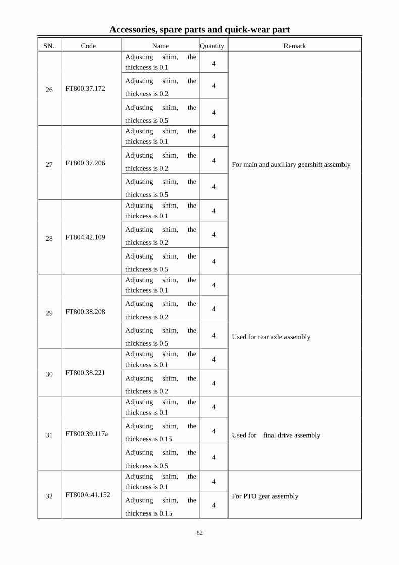
Accessories, spare parts and quick-wear part
SN.. Code Name Quantity Remark
26 FT800.37.172
Adjusting shim, the thickness is 0.1 4
For main and auxiliary gearshift assembly
Adjusting shim, the
thickness is 0.2 4
Adjusting shim, the
thickness is 0.5 4
27 FT800.37.206
Adjusting shim, the thickness is 0.1
4
Adjusting shim, the
thickness is 0.2 4
Adjusting shim, the
thickness is 0.5 4
28 FT804.42.109
Adjusting shim, the thickness is 0.1
4
Adjusting shim, the
thickness is 0.2 4
Adjusting shim, the
thickness is 0.5 4
29 FT800.38.208
Adjusting shim, the thickness is 0.1
4
Used for rear axle assembly
Adjusting shim, the
thickness is 0.2 4
Adjusting shim, the
thickness is 0.5 4
30 FT800.38.221
Adjusting shim, the thickness is 0.1
4
Adjusting shim, the
thickness is 0.2 4
31 FT800.39.117a
Adjusting shim, the thickness is 0.1
4
Used for final drive assembly Adjusting shim, the
thickness is 0.15 4
Adjusting shim, the
thickness is 0.5 4
32 FT800A.41.152
Adjusting shim, the thickness is 0.1
4
For PTO gear assembly Adjusting shim, the
thickness is 0.15 4
82

Accessories, spare parts and quick-wear part
SN.. Code Name Quantity Remark
Adjusting shim, the
thickness is 0.5 4
33 FT804.42.109
Adjusting shim, the thickness is 0.1
4
For transfer case assembly Adjusting shim, the
thickness is 0.2 4
Adjusting shim, the
thickness is 0.5 4
4.2.2 Onboard tools Table 4-2 Onboard tools
SN.. Code Name Quantity Remark
1 QB/T 2564.4 Screwdriver for slotted head screws
1×5.5×125P 1
2 TD800.96-08 Screwdriver for recessed head
screws 6×150P 1
3 GB/T 3390.1 Socket, manual socket wrench
18×12.5L 1
4 GB/T 3390.1 Socket, manual socket wrench
21×12.5L 1
5 GB/T 3390.1 Socket, manual socket wrench 24×12.5L
1
6 GB/T 3390.1 Socket, manual socket wrench
27×12.5L 1
7 GB/T 3390.1 Socket, manual socket wrench 30×12.5L
1
8 GB/T 3390.3 Handle, manual socket wrench
H12.5 1
9 GB/T 3390.4 Extension bar, manual socket
wrench 204×12.5×250a 1
10 JB/T 7942.1 Lever-type grease gun A200 1
11 JB/T 3411.47 Installing tong for circlip for shaft
B2.5 1
12 JB/T 3411.48 Installing tong for circlip for hole
A2.5 1
13 TD800.96-09 Hexagonal wrench 8×160 1
14 GB/T 4388 Double open end wrench 8×10×119 1
83
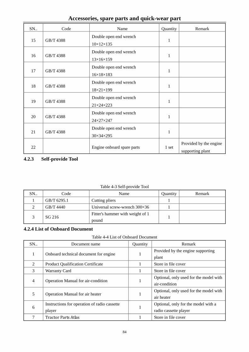
Accessories, spare parts and quick-wear part
SN.. Code Name Quantity Remark
15 GB/T 4388 Double open end wrench
10×12×135 1
16 GB/T 4388 Double open end wrench
13×16×159 1
17 GB/T 4388 Double open end wrench
16×18×183 1
18 GB/T 4388 Double open end wrench
18×21×199 1
19 GB/T 4388 Double open end wrench
21×24×223 1
20 GB/T 4388 Double open end wrench
24×27×247 1
21 GB/T 4388 Double open end wrench
30×34×295 1
22 Engine onboard spare parts 1 set Provided by the engine
supporting plant
4.2.3 Self-provide Tool
Table 4-3 Self-provide Tool SN.. Code Name Quantity Remark
1 GB/T 6295.1 Cutting pliers 1 2 GB/T 4440 Universal screw-wrench 300×36 1
3 SG 216 Fitter's hammer with weight of 1 pound
1
4.2.4 List of Onboard Document Table 4-4 List of Onboard Document
SN.. Document name Quantity Remark
1 Onboard technical document for engine 1 Provided by the engine supporting plant
2 Product Qualification Certificate 1 Store in file cover 3 Warranty Card 1 Store in file cover
4 Operation Manual for air-condition 1 Optional, only used for the model with air-condition
5 Operation Manual for air heater 1 Optional, only used for the model with air heater
6 Instructions for operation of radio cassette player
1 Optional, only for the model with a radio cassette player
7 Tractor Parts Atlas 1 Store in file cover
84

Accessories, spare parts and quick-wear part
8 Engine Qualification Certificate 1 Provided by the engine supporting factory, and stored in file cover
9 Tractor Operation Manual 1 Store in file cover 10 Packing list of onboard items 1
Note: Please check and accept the engine onboard tools, spare parts and documents according to the
packing list of the diesel engine.
4.3 Quick-wear Part
Quick-wear parts of LOVOL-TD Series tractors include: all fuses and bulbs used in the complete machine,
shown as Table 4-5.
Table 4-5 Quick-wear part list SN.. Code Name Qty/Unit Position for use
1 TD9600000500 Ordinary fuse (5A)
2 Central electric box
2 TD9600000700 Ordinary fuse (10A)
8 Central electric box
3 TD9600000800 Ordinary fuse (15A)
2 Central electric box
4 TD9600000900 Ordinary fuse (20A)
3 Central electric box
5 12V-H4-55/60W Double- filament bulbs of low and high beams
2 Headlamp
6 12V-21W Steering bulb 6 Headlamp, handrail lamp (model with cab),
rear tail-lamp
7 12V-5W Position lamp (front)
4 Headlamp, handrail lamp (model with cab)
8 12V-10W Position lamp (rear)
2 Rear tail-lamp
9 12V-H3-55W Rear working bulb
2 Rear working lamp
10 12V-35W Top working bulb 4 Top working lamp
11 12V-21W Brake bulb 2 Rear tail-lamp
12 TD800.481.2 Fusible link (1.0) 1 Engine harness
Important:
1. Various spare parts, tools and quick-wear parts listed above are specifically designed for this tractor.
Please keep them in a safe place to prepare for use, maintenance and service of the tractor. Failure to do so
can affect the use of the tractor’s function.
2. Only use the formal LOVOL parts to perform maintenance on your tractor. Failure to do so can
affect the tractor’s functions, performance and service life.
85

Accessories, spare parts and quick-wear part
86

Maintenance instructions 5 Maintenance instructions
Technical maintenance is a series of technical maintenance measures which include cleaning, checking,
lubricating, fastening, and adjusting each part of the tractor or replacing some parts regularly. Regular
maintenance can avoid technical conditions of each part from deteriorating rapidly, reduce failure rate and prolong
its service life, and keep the tractor working in good conditions.
Important:
1. All maintenance work should be carried out by the trained and qualified persons, who are
familiar with the tractor performances so as not to damage the tractor.
2. In order to keep the tractor running in a normal operation and prolong its service life, the
technical maintenance procedures should be strictly observed.
3. Within the warranty period, if any damage occurs arising from any operator who is unspecialized
or not familiar with the tractor performances, or the maintenance which is not made by ruled within the
specified period from the manufacturer, the relative warranty will be invalid.
4. It is prohibited to adjust the relief valve opening pressure of engine, hydraulic system and air
brake system, safety overflow pressure of constant overflow pump overflow valve and opening pressure
of radiator cap without permission. Otherwise it can cause damage to the tractor, affect the performance
of tractors and lose the relative service right of warranty of tractors.
5.1 Technical maintenance procedures
Service period of FOTON-TD wheeled tractor is calculated according to cumulative working hours
including technical maintenances of every shift [every 10h], every 50h, every 200h, every 400h, every 800h,
and every 1600h, as well as special maintenance in winter and maintenance for long-time storage.
5.1.1 Technical maintenance of every shift
Dusts and greasy dirt on tractor shall be cleared away.
Check and secure all fasteners outside of tractor if needed, especially the fixing nuts from the front
and rear wheel;
Check the fluid level in the oil sump, radiator, fuel tank, hydraulic steering oil reservoir, service brake
oil reservoir and hydraulic lifter etc and fill them if necessary. If checking the level in oil sump, please park
the tractor on the flat ground and go ahead after15min of stopping.
Lubricating grease shall be added according to Maintenance and Service Schedule 5-1;
Pressures of front and rear wheels shall be checked and inflated as required when there is any
insufficiency;
Check the free travel of the main / auxiliary clutch pedal and the brake pedal respectively.
"Three leakage"-air leakage, oil leakage and water leakage of the tractor shall be checked and
removed;
Maintain the diesel engine according to "Technical maintenance of daily shift".
87

Maintenance instructions
5.1.2 Technical Maintenance for Every 50 Hours
All contents of technical maintenance of every shift shall be done;
Lubricating grease shall be added according to Maintenance and Service Schedule 5-1;
Check the oil level of the oil bath type air filter and dedust it.
Maintain the diesel engine according to Level-1 Technical Maintenance".
5.1.3 Technical Maintenance for Every 200 Hours
All contents of technical maintenance of every 50 hours shall be done;
Change the lubricant in engine oil pan.
Clean and maintain the oil pan of the oil bath type air filter;
Clean the hydraulic fluid filter of the lifter. If necessary, replace the filter element.
Maintain the diesel engine according to Level-2 Technical Maintenance".
5.1.4 Technical Maintenance for Every 400 Hours
All contents of technical maintenance of every 200 hours shall be done;
Lubricating grease shall be added according to Maintenance and Service Schedule 5-1;
Inspect oil level of the main drive and final drive of the front drive axle, and refill oil if necessary;
Inspect oil level of the transmission system and lifter, and refill oil if necessary;
Inspect free travel of the parking brake handle, and adjust it if necessary;
Clean and maintain the filter of the hydraulic steering oil tank;
Maintain the diesel engine according to Level-2 Technical Maintenance".
5.1.5 Technical Maintenance for Every 800 Hours
All contents of technical maintenance of every 400 hours shall be done;
Replace the hydraulic oil for the hydraulic steering system;
Replace the hydraulic oil for the transmission and lifter;
Check valve clearance of diesel engine
Check and adjust the injection pressure of the fuel injection pump.
Conduct cleaning and maintenance of the fuel tank;
Maintain the diesel engine according to Level-3 Technical Maintenance".
5.1.6 Technical Maintenance for Every 1600 Hours
All contents of technical maintenance of every 800 hours shall be done;
Clean and maintenance the diesel engine cooling system;
Replace the lubricating grease for the central and final transmission of the front drive axle;
Checking, adjustment and maintenance of the starter motor.
Maintain the diesel engine according to Level-3 Technical Maintenance".
88

Maintenance instructions 5.1.7 Special maintenance in winter
Change with the lubricant and fuel for winter;
The antifreeze should be adopted if temperature is below 0℃in winter.
Before working each shift, please follow the requirements for winter to start the engine.
In winter, the battery discharging rate of battery should not be more than 25%, please keep higher
charging rate.
If operation completed, please park it in windshield warm shed.
5.1.8 Technical maintenance of Tractor's Long-term Storage
If the tractor has been stored for less than one month, and the time does not exceed 100 hours since the
engine oil was replaced, special technical maintenance is not required. If the tractor has been stored for more
than one month, special technical maintenance shall be done according to Section 6 Storage specified in this
Manual.
5.2 Technical maintenance operation
5.2.1 Tractor Maintenance
Table 5-1 Maintenance of FOTON-TD Series Tractor
SN.. Maintenance parts Operation contents Times Maintenance period
1 Engine oil pan Checking liquid
level 1 Every shift
2 Oil bath type air filter Checking liquid
level 1 Every shift
3 Battery Checking liquid
level 1 Every shift
4 hydraulic steering oil tank Checking liquid
level 1 Every shift
5 Radiator (Water Tank) Checking liquid
level 1 Every shift
6 Water Pump Shaft of Engine Adding lubricating
grease 1 Every shift
7 Fuel Injection Pump Checking liquid
level 1 Every shift
8 Brake oil tank Checking liquid
level 1 Every shift
89

Maintenance instructions
9 Rear wheel hub Adding lubricating
grease 2 Every shift
10 Main Clutch Adjusting free stroke 1 Every shift
11 Auxiliary clutch Adjusting free stroke 1 Every shift
12 Driving brake Adjusting free stroke 2 Every shift
13 Fan belt Checking tensity 1 Every 50 work hours
14 Steering cylinder Adding lubricating
grease 1
Every 50 work hours
15 Front axle kingpin bushing Adding lubricating
grease 2 Every 50 work hours
16 Front axle swing shaft, 4WD Adding lubricating
grease 2 Every 50 work hours
17 Central swing pin bushing of front
axle
Adding lubricating
grease 1 Every 50 work hours
18 Rocker shaft of main and auxiliary
clutches
Adding lubricating
grease 4 Every 50 work hours
19
Diesel Filter Replacing filter
Element 1
Every 200 operating hours
after the run-in period is
finished.
20
Rotary oil filter Replacing filter
1
Every 200 operating hours
after the run-in period is
finished.
21 Hydraulic oil absorption filter of
lifter
Clean or replace the
filter element. 1 Every 200 work hours
22 Hydraulic oil return filter of lifter Clean or replace the
filter element. 1 Every 200 work hours
23 Fuel Injection Pump Replace the
lubricant 1 Every 200 work hours
24 Engine oil pan Replace the
lubricant 1 Every 200 work hours
25 Oil pan of oil bath type air filter Cleaning and
maintenance 1 Every 200 work hours
26 Power train and lifter Check the oil level 1 Every 400 work hours
90

Maintenance instructions
27 Parking brake Adjusting free stroke 1 Every 400 work hours
28 Breather element Clean filter element 2 Every 400 work hours
29 Front Wheel Adding lubricating
grease 2 Every 400 work hours
30 Central transmission of the front
drive axle
Check the oil level 1 Every 400 work hours
31 Oil cup of kingpin of front drive
axle
Adding lubricating
grease 2 Every 400 work hours
32 Final transmission of the front drive
axle
Check the oil level 2 Every 400 work hours
33 Hydraulic steering oil tank filter Clean and maintain 1 Every 400 work hours
34 hydraulic steering oil tank Replace the
lubricant 1 Every 800 work hours
35 Fuel Tank Clean and maintain 1 Every 800 work hours
36 Intake/Exhaust Valve of Engine Adjusting valve
clearance 8 Every 800 work hours
37
Fuel injector Adjusting the
pressure of injection
pump
4 Every 800 work hours
38 Power train and lifter Replace the
lubricant 1 Every 800 work hours
39 Engine cooling system Clean and maintain 1 Every 1600 work hours
40 Engine cooling system by using
antifreeze solution
Replacing antifreeze
solution 1
2 years or every 1600 work
hours
41 Central transmission of the front
drive
Replace the
lubricant 1 Every 1600 work hours
42 Final transmission of the front drive
axle
Replace the
lubricant 1 Every 1600 work hours
43 Brake fluid for the brake system. Replace the brake
fluid 1 Half a year
5.2.2 Technical maintenance operation
5.2.2.1 Battery Maintenance
● Service of maintenance-free battery
91

Maintenance instructions
Usually, the maintenance-free battery does not need to be maintained
specially. Observe the color shown in the hydrometer observation hole. Green
indicates the battery is fully charged. Black indicates the battery is short of
power. White indicates the battery almost runs down. If the observation hole
shows black, charge the battery immediately. If the observation hole shows
white, replace the battery.
Fig 5-1 Inspection of battery condition
Warning:
The battery contains electrolyte which is highly corrosive. Do not get electrolyte in your eyes or on
your skins or clothing. If so, rinse your eyes or skin with large quantities of water. Call a physician
immediately to avoid serious burns. ● Cautions for Use and Service of Maintenance-free Battery
1. Store the battery in a dry, clean and well-ventilated place at 5~40 ℃.
2. Do not expose the battery to direct sunlight, and keep it away from any heat source (heating equipment,
etc.) for at least 2m.
3. Avoid rain and dust and other impurities, and prevent the battery from discharging due to external short
circuit.
4. Do not put the battery upside down or let it lie down to avoid any mechanical shock or great pressure
5. To store the battery, make sure it is fully charged.
6. Avoid tilting the battery when placing it. Do not put the battery upside down or bump it.
7. Check the battery voltage once every 3 months. When its voltage is below 12.5V, charge the battery in
time. Failure to do so can cause the battery to be charged difficultly after long-term storage, and affect the
battery service life.
8. When the battery is used or stored, always make sure its vent hole is unblocked to prevent the battery
from deformation or explosion.
9. In the process of charge and discharge, make sure the battery is in a well-ventilated environment to
eliminate the acid mist and combustible gases generated during charging and to keep the indoor air fresh to
reduce the erosion of acid molecules to the personnel and equipment and to avoid ignition of
combustible gases.
10. Always check the color of the charge density meter on the battery cover plate, and according to the
92

Maintenance instructions
color, perform service, maintenance and replacement on the battery.
● Charging mode
Usually, there are constant-current charging, constant-voltage current-limiting charging and other charging
mode. We recommend you using the constant-voltage current-limiting charging mode.
1. Constant-current charging
Charge your battery at 00.1C20A (i.e., 12A) to 16V, and then continue to charge it at 0.05C20A. When the
battery voltage can keep unchanged for 1 to 2 hours, you can finish charging it (with a voltage difference
between the two times <0.03V), or when the battery continues to be charged for 3-5 hours after its voltage
reaches 16V, you can finish it.
2. Constant-voltage charging
With a constant voltage between 14.8V~15.5V, and the maximum current 0.25C20A (i.e., 30A), after the
charging current ≤0.5A, you can continue to charge the battery for 3 hours. The total charging time should
be controlled within 24 hours.
● Charging cautions
1. Be sure to connect the positive battery terminal to the positive pole of the charger and connect the
negative battery terminal to the negative pole of the charger.
2. Lay the battery level and make sure the charging connections are secure and firm.
3. When charging, make sure the battery temperature does not exceed 45℃. Otherwise, cool the battery
through water bath or reduce the charging current temporarily or reduce the charging voltage and other
measures.
4. Be sure to charge the battery in a well-ventilated room. The battery gives off explosive hydrogen
during normal charging. If the hydrogen accounts for 4%~7% of the gases in the room, a spark or flame
can cause explosion. Especially, there should be no smoking or open fire in the charging room.
5. When connecting the charging cables, be sure to avoid short-circuit.
5.2.2.2 Check and maintenance of service brake oil tank
The service brake oil tank is set on right side of the bonnet support. The brake fluid should be 10~15mm
above the boss in normal condition. When the brake fluid level is less than the value, it is required to find out
the oil leakage causes, and handle the problem, as well as replenish the oil.
Attentions: 1. Correct brake fluid level is critical to normal operation of the brake system; Excessively low
93

Maintenance instructions
brake fluid level will result in failure of the brake and major safety hazard accidents;
2. The hydraulic brake oil must be synthetic oil, and brake oil containing alcohol cannot be used or
other machine oil is used in place of the same brake oil, so as to avoid occurrence of unexpected safety
hazard accidents resulted from brake failure.
5.2.2.3 Check and maintenance of hydraulic steering oil tank
Hydraulic steering oil tank is mounted on the upper side of the engine. Open the cap (with dipstick) to
check whether there is oil trace. If there is no oil trace, it indicates the oil level is insufficient. Find out the
cause and then add oil to middle scale of dipstick by removing oil tank. Then reinstall again. Be sure there is
no leakage of hydraulic steering oil tank, oil pipe and connections. Otherwise, steering failures will occur.
Regularly clean and replace the hydraulic oil filter screen.
When checking the oil level, please check whether the vent valve (rivet shaped) on the center of oil
reservoir cap could lift or lower smoothly. if any oil contamination, please remove it.
5.2.2.4 Maintenance of oil bath type air filter
By opening the locking hook at lower part of the filter, dismantle the oil basin at its bottom, empty the
contaminated oil, and clean it with kerosene or diesel, as well as clean the filter element at the same time; then,
refill new oil to the specified oil level, and re-install it properly.
5.2.2.5 Use and maintenance of dry-type air filter
When the air filter blockage alarm lamp is on, must conduct maintenance of the dry type air filter element.
The air filter should be maintained frequently
according to the dust conditions in the operating
environment. It is recommended that it is maintained
every shift in dusty environment.
The equipment should be inspected every day or
when refilling fuel, so as to ensure all connections
between the air filter and engine are sealed properly,
including all hose fittings, and end cover of the air
filter housing. In case of discovering any crack, have it
repaired immediately, and record it in the machine
maintenance records.
The built-in dry air filter element is divided into two stages: i.e. primary filter element and safety filter
element.
During maintenance, the primary filter element should be dismantled carefully to prevent dust from
ingression into the filter housing.
B A
Fig.5-2 Dry-type Air Filter A. Safety filter element; B. Primary filter element
94

Maintenance instructions
It is recommended that the safety filter element should be replaced when the primary filter element has
been replaced for more than three times. If the safety filter sounds very clean and before the replacement date,
do not loosen the wing locknut, and do not change mounting status of the safety filter element.
When it is found that replacement of the safety filter element is required, inspect the wing locknut to
ensure it is tightened securely. At this moment, do not loosen the locknut. When the safety filter element has
not been replaced, clean the filter housing, and remove dust accumulated in the housing. Do not use
compressed air to clean the air filter housing.
During replacement of the safety filter element, dismantle the wing locknut and washer, and carefully
remove the filter element from the housing. Prior to installation of a new safety filter element, use a piece of
clean and wet cloth to wipe the mounting surface of the safety filter element.
Inspect each new filter, and ensure that the new filer model is correct. Inspect the filter is cracked/damaged
or wrinkled, and its lining is cracked/damaged, or the washer is damaged. If damage to any part is found,
discard the damaged part, install a new filter element, and use a washer and wing locknut to tighten it. Ensure
that the new filter rubber washer is mounted between the wing locknut and filter element, and simultaneously
ensure an air intake resistance indicator is mounted.
Re-assemble an air filter as per reverse dismantling sequence. Mount the end cover, and before fixing the
clamp or wing locknut, ensure that the end cover is located and seated accurately.
Important: Correct use and maintenance of air filter is directly related to the service life of engine,
therefore it must be kept clean all the time. During farmland operation, be sure to check, clean the oil
after each shift. After maintenance, must ensure that the air filter element is tightly against the air filter
to prevent presence of a gap between the two parts, so as to avoid ingression of dust or mud into the
engine resulting in engine scuffing, abnormal wear and downward exhaust and other faults!
5.2.2.6 Adjustment of fan belt tension
Pressing the central part of the fan adhesive tape with thumb by applying a force of(29.4~49.0)N gives a
press distance of (15±3)mm. If these requirements cannot be met, perform adjustment as follows:
Loosen the retaining nut on the generator bracket and pull the generator outward to tension the belt, and
then tighten the retaining nut.
5.2.2.7 Inspection of oil level in engine oil pan and replacement of oil
Pull out the dipstick A on the front left of the oil pan. Check whether the oil level is between the UPPER
and LOWER marks. If the oil level is under the lower scale line, remove the oil filler cap on the engine timing
gear housing cover.
During maintenance and oil replacement, unscrew the oil drain plug at lower part of the oil sump to empty
the contaminated oil and clean it, and then re-inject new oil.
95

Maintenance instructions
5.2.2.8 Protection of front axle
Add grease to the kingpin sleeve, front axle main balance pin sleeve, the ball joint at the both ends of
steering cylinder and ball joint of tie-rod. Check whether the nuts from both tie-rod ball pin and pin at the both
ends of cylinder are loose.
5.2.2.9 Maintenance of fuel filter
For the fuel filter, see the figure. The engine adopts 2 stage of filters
connected in series, of which the left filter is the 1st stage filter, and the
right filter is the 2nd stage filter. Cleaning of the paper filter element is
not allowed. After run-in period is finished, the 1st filter element should be
replaced every 200 operating hours of the engine. During replacement,
the 2nd filter element is installed in the 1st stage, and the 2st filter element
is replaced with a new one.
Fig. 5-3 Fuel filter
5.2.2.10 Maintenance of the rotary oil filter
The rotary oil filter is located at lower left side of the engine, and should be replaced according to
technical requirements every 200 operating hours after run-in period.
The rotary oil filter is replaced as a whole, and must be tightened during installation.
5.2.2.11 Maintenance of hydraulic oil filter
The hydraulic oil absorption filter of the lifter is located at the lower right part of the engine. It is
maintained as per technical requirements. The method is as follows: unscrew the rear end cover of the
hydraulic filter, remove the net type filter element, and use gasoline to clean it and use compressed air to purge
it. When it is difficult to clean the filter element or the filter element is damaged, it should be replaced with a
new one. The oil return filter is located on the left side of the lifter housing, and should be cleaned every 200
operating hours. When it is difficult to clean the filter element or the filter element is damaged, it should be
replaced with a new one.
5.2.2.12 Inspection of oil level at end of the front drive axle
The screw plug for inspection of drive oil level at end of the front drive axle is located at the front wheel hub,
so that the screw plug port is at horizontal position and the new oil is injected to the screw plug port.
5.2.2.13 Oil level inspection of the front drive housing
96

Maintenance instructions
Fig. 5-4 Oil level inspection of the front drive housing
When inspecting oil level of the front drive housing (see Figure 5-4), the screw plug "A" should be
removed, and the oil level should reach the screw plug port; otherwise oil should be injected. During
replacement of the oil, empty the dirty oil from the screw plug "B", and tighten the screw plug "B", and inject
new oil from the screw plug "A".
5.2.2.14 Injection of the front wheel lubricating oil
Lubricating grease of the front wheel of FOTON-TD Series tractors is injected from the hub oil cup inside
the front wheel.
5.2.2.15 Lubrication of the front drive axle kingpin
1 oil cup is at both ends of the middle pendulum shaft of the front drive axle of the FOTON-TD Series
tractors, respectively. The lubricating grease should be filled on a regular basis, and is usually re-filled every 50
operating hours.
5.2.2.16 Maintenance of Power train
When checking the oil level, please park the tractor on the flat ground. Shut down the engine. Screw out
and clean the dipstick on the right side of rear axle housing. Insert the dipstick to check the oil level. If the oil
level is below the lower scale of dipstick, please fill the drive oil to the zone between the upper and lower
scales (measurement should be taken after 5min when filling oil is over). When replacing the lubricant, please
remove the drain plug located on the bottom of transfer case housing to drain the used oil. Moreover, use the
diesel oil to clean it. Tighten the drain plug and add the new oil.
5.2.2.17 Maintenance of Lifter
Park the tractor on the flat ground and lower the lifting arm to lowest position. Shut down engine and
screw out the dipstick on the lifter cover to check the oil level. If the level is below lower scale, please fill it to
the zone between upper and lower scales. To change the hydraulic oil, remove the drain plug to drain the used
oil. Then clean and fill new oil as required.
5.2.2.18 Maintenance of Fuel Tank
97
Maintenance instructions
Park the tractor on level ground and shut off the engine, and then remove the drain plug at the bottom of
the fuel tank and drain its deposition.
The fuel tank diesel filter is functioned for filtrating fuel, depositing moisture and foreign material. Please
regularly check or clean it.
5.2.2.19 Inspection of Tire Inflation Pressure
Check the tire pressure with a barometer. For the tire pressure, see the Tractor Technical Specifications.
Too high or too low of tire pressure will cut down tire service life, and have an impact on driving and handling
the tractor, resulting in accidents.
5.2.2.20 Maintenance of engine cooling system
Engine coolant can be boiled water or antifreeze. Validity period of antifreeze is 2 years or 1600 h.
Antifreeze shall be drained and the cooling system shall be washed if beyond the time limit, then new freeze
shall be added.
Precautions for use of the radiator:
● Before starting, please check whether coolant is filled up in the radiator and whether there is any leak.
Check whether the radiator cap is tightened.
● Frequently check whether there is weed, dust or oil contamination in the radiator core. Remove it if
necessary.
● Periodically clean the scale in the cooling system to maintain the thermal dissipation on the heat
exchange surface.
● Periodically look over the thermostat that will affect the cooling water cycling and therefore cooling
effect.
Cleaning of the cooling system:
During external cleaning of the radiator, remove weeds foreign bodies before cleaning, and use hot water
(or water vapor) to wet its core, and dry it with compressed air.
During removal and cleaning, have it soaked in water solution with 1~2% detergent. The solution
temperature should be 80~100℃. The radiator should be shook in the solution to remove contaminant, and
wash clean it with clear water.
Cleaning of scale in the cooling system: in the shift before maintenance, the cooling system shall be filled
with a solution, whose proportion is adding 750 g caustic soda and 150 g kerosene in 10 L water. Let the engine
run at medium speed for 5 ~ 10 minutes and let the cleaning solution sit for 10~12h (Note: Be sure to keep the
engine warm to prevent freezing in winter.), and then, stop the engine and drain the cleaning solution after the
engine is re-started to operate at middle speed for 20 min. After the engine gets cool, insert a water pipe into
the water tank for flushing, and at this moment, the water drain valve at bottom of the water tank should be
opened. After rinsing, turn off the drain valve, and add water to let the engine run for 20 minutes, and then drain
the water. After the engine is cooled down, new antifreeze or cooling water shall be added according to
98

Maintenance instructions
regulations.
Important:
1. In winter, frequently check the antifreeze concentration according to ambient temperature. If
necessary, timely recover to normal concentration. For the tractor without antifreeze, wait until the
cooling water temperature drops below 70℃, and then drain the cooling water while the engine idling to
prevent the cooling water from being frozen, cracking the engine block.
2. To prevent blockage of the water pipe of the radiator core and water deposit in the same pipe
must use anti-freeze fluid produced by specified manufacturers.
3. The heat radiator cannot be in contact with any acid, alkali or other corrosive substances, so as to
avoid corrosion of the heat radiator;
4. During installation and cleaning of the heat radiator, pay attention to prevent damage to the
radiator strap and collision with the radiating pipe.
5.2.2.21 Maintenance and care of individual breathers
After shutdown of the tractor, remove individual breathers one by one, use clean diesel for cleaning, and
after cleaning, re-install them back to the tractor. During assembling, pay attention to remove air trapped in the
oil line.
5.2.2.22 Exhaust of fuel system
Prolonged tractor storage or
replacing the diesel oil filter, as well as
emptying the fuel tank, can cause air in
the fuel lines. Air in the fuel system will
make the engine difficult to start.
Bleed the air by observing the
following steps when the tank is full of fuel and the fuel line switch is turned on: Loosen the bleed screw A of
the fuel filter, and pull the draw knob B of the fuel delivery pump up and down, until the diesel oil spills from
the bleed screw hole without bubbles. Tighten the bleed screw A again, and loosen the bleed screw on the
injection pump and pull up and down the draw knob B of the hand pump of the fuel delivery pump, until the
diesel oil spills from the bleed screw hole without bubbles, and then tighten the bleeder screw C.
Fig. 5-5 Exhaust of engine fuel system
99

Maintenance instructions
Important:
1. Only apply the qualified high-quality light oil to the engine, generally No. 0 light diesel oil in
summer, and No. -10 light diesel oil in winter (For details see the operation manual of diesel engine); The
diesel oil must be pure. Be sure to precipitate and purify it for at least 48h before use. Failure to do so can
damage the engine
2. Frequently check the lubricant level for the ZHB fuel injection pump. Fill to scale position if
necessary. Change the lubricant every 200h. The lubricant grade used in injection pump should be same
as that used in diesel engine to avoid affecting fuel injection pump performance and service life.
5.2.2.23 Air bleeding of the brake system
After dismantling the oil pipe of the brake system or conducting inspection and adjustment of the brake
smoothness (synchronism), must remove air trapped in the brake system.
The air removal of the brake system should be carried out by a
trained, skilled and experienced personnel according to following steps:
first have the brake oil tank full of oil, slowly depress the left brake pedal
to build brake pressure. Unscrew the air bleed plug "A" above the brake
housing by half turn. Tighten the air bleed plug "A", and repeat the
above-mentioned operation until the spilled oil is free from air bubbles.
Depress the brake pedal again to build oil pressure. When the pedal reaches the normal travel, the oil
pressure is built completely (reach the specified pressure). Note: Finally, wipe away the oil spilled onto the
half shaft housing to prevent coming-off of the paint. Conduct air bleeding of the brake on other side in the
above-mentioned sequence. Finally, inject oil into the brake oil tank to the specified oil level.
Warning: If the air is not bled thoroughly, the brake system may be failed!
5.3 Adjustment of Tractor Chassis:
5.3.1 Adjustment of clutch
● The main clutch control mechanism is adjusted according to following steps:
a. Adjust jointing length of the middle lever 6 to obtain a 28~40mm free travel of the main clutch pedal,
and then tighten the tie rod nut 5.
b. Adjust extension length of the limit screw 3 to limit full travel of the main clutch pedal within
Fig. 5-6 Exhaust of brake
100

Maintenance instructions
140~150mm, so that the main clutch is disengaged thoroughly, the tractor can be shifted between gears flexibly,
and then the limit screw is tightened with a nut.
Fig. 5-7 Adjusting free travel of the clutch pedal
1. Auxiliary clutch control handle
2. Pedal 3. Limit screw 4. Upper draw bar 5. Nut
6. Middle lever 7. Lower draw bar
8. Transition lever 9. Main clutch rocker arm
10. Limit screw
11. Auxiliary clutch rocker arm
12. Nut 13. Auxiliary clutch pull rod
14. Pull rod fork 15. Nut
16. Cotter pin 17. Pin 18. Floor
● The auxiliary clutch control mechanism is adjusted according to following steps:
a) Adjust length of the auxiliary clutch pull rod 13 to obtain a 45mm~55mm free travel of the auxiliary
clutch control handle 1, and then tighten the pull rod nut.
b) Adjust length of limit screw 10 on right side of the gearbox, limit full travel of the auxiliary clutch
control handle 1 within 255mm~270mm to get the auxiliary clutch disengaged thoroughly; the PTO can change
gear flexibly, and then limit screw 10 is tightened with a nut.
Internal adjustment
The clutch has been adjusted before delivery, and no adjustment is usually required. If desired to conduct
adjustment, it can be adjusted by following method:
Adjustment of main clutch: Unscrew the nut 18 and turn the limit screw 17 to obtain a clearance of 2
~2.5mm between the end B of the main clutch release lever 14 and the release bearing, and then tighten the nut
101

Maintenance instructions
18. When it is adjusted by this method, must ensure that the end of 3 main clutch release levers is in the same
vertical plane, and use a feeler gauge for inspection. The deviation should not be more than 0.2mm.
b. Adjustment of auxiliary clutch: Unscrew the small hex self-locking nut 4 to obtain a clearance of 2
~2.5mm between the end A of the auxiliary clutch release lever 8 and the auxiliary clutch release plate. Then,
firmly clamp the round end of the small hex self-locking nut 4, so that the nut is locked firmly. During
adjustment, must ensure that the end of 3 clutch release levers is in the same vertical plane, and use a feeler
gauge for inspection. The deviation should not be more than 0.2mm.
Adjustment of the release lever position is shown in Figure 5-8. When re-installing the clutch assembly,
the distance between the end A of the main clutch release lever and the end surface of the auxiliary clutch
driven plate assembly 2 must be 103±0.5mm [For the 11" clutch, the distance should be 96±0.5mm]; the
distance between the end B of the auxiliary clutch release lever 8 and the end surface of the auxiliary clutch
driven plate assembly must be 137±0.5mm [For the 11" clutch, the distance must be 121±0.5mm].
1. Disc spring 2. Auxiliary clutch driven plate assembly 3. Auxiliary clutch pressure plate unit 4.
Small hex self-locking nut 5. Coupling lever 6. Short pin 7. Long pin 8. Auxiliary clutch release
Fig. 5-8 12" clutch mounting
102

Maintenance instructions
lever9. Clutch cover 10. Main clutch pressure plate unit 11. Main clutch driven plate assembly 12.
Auxiliary clutch release plate 13. Main clutch release bearing 14. Main clutch release lever 15. Lever
unit 16. Pin 17. Limit screw 18. Nut
Important: The free travel of the clutch should be inspected and adjusted frequently to ensure that the
free travel of the pedal is within 28~40mm, so as to avoid abnormal wear of the clutch.
Important:
1. During use of the clutch, must note that the clutch is disengaged rapidly and thoroughly, and be
engaged smoothly, so as to avoid early damage to the clutch.
2. During driving of the tractor, do not place your foot on the clutch pedal. Semi-engagement of the
clutch is not allowed to reduce driving speed of the tractor, and sudden engagement of the clutch is not
allowed for climbing or overpassing a barricade, so as to avoid damage to the clutch.
3. The clutch lining surface should be free from oil stains. In case that the clutch lining surface is
oil-stained, it should be cleaned with gasoline, and should not put into service until it gets dry, so as to
avoid early damage to the clutch.
4. Every 50 hours, inject appropriate quantity of lubricating grease into the oil cup on the left/right
front connecting supports, respectively, so as to lubricate the main/auxiliary clutch rocker arm shaft,
ensuring that the rocker arm shaft rotates flexibly.
5.3.2 Adjustment of brake control mechanism
103

Maintenance instructions
For adjustment of the brake, see Figure
By adjusting the limit screw 11, the height from the
floor to the pedal center should be within 175~185mm; By
adjusting the limit screw 3, ensure that the clearance
between the limit screw 3 and the brake pump is within
3~4mm, so that the free travel of the pedal is within
12~16mm; the working travel is within 110~130mm. The
working travel of the hand brake control handle is within
220~250mm. By adjusting length of the hand brake pull
rod, ensure that parking braking is realized reliably within
specified working travel. The specific adjustment
method is as follows: Set the hand brake control handle to
the initial position (horizontal position of the control
lever), remove the cotter pin, withdraw the pin 7, loosen
the nut 9, turn the pull rod 8 to adjust effective length of the hand brake pull rod until the working travel meets
requirements.
Attentions: 1. The free travel of the left/right brake pedal of the tractor must be adjusted consistently;
otherwise, the tractor will deflect toward one side during emergency braking, resulting in dangerous
accident;
2. For the purpose of reliability, the brake test should, after adjusting the brake control mechanism,
be carried out by following steps: have the right/left brake pedals interlocked, and move the tractor to a
dry and flat road; after the main clutch is disengaged in high speed straight driving conditions, use the
brake for emergency braking, and then park the vehicle to inspect sliding imprints of the drive wheels on
the road. If the imprints of the left/right drive wheels on the road are consistent (the imprints on both
sides are straight, in parallel with each other, and equal in their length), it indicates that it is adjusted
properly; otherwise, it should be adjusted again. If it cannot be adjusted properly for several times, it is
required to inspect the interior of the brake.
Fig. 4-8 Adjustment of
Fig. 4-8 Adjustment of brake control
1. Hand brake control handle 2. Pedal 3.
Limit screw 4. Brake pump 5. Brake oil tank
6. Cotter pin 7. Pin 8. Pull rod fork
9. Nut 10. Floor 11. Limit screw
Fig. 5-9 Adjustment of
104

Maintenance instructions 5.3.3 Adjustment of the rear axle
5.3.3.1 Adjustment of the bevel pinion shaft bearing
Adjustment of the bevel pinion shaft bearing is
shown in figure.
The conical roller bearing 3 and 5 on the bevel
pinion shaft 6 are pre-tightened. During use, wear
of the bearing may result in end-play of the bevel
pinion shaft. During repeated adjustment, a
pre-tightening resisting moment of 1.5~2.5N·m
[Have a rope wound onto the active arc splined
shaft by 2-3 turns, and use a spring balance to pull
the rope to have the active arc rotated. The spring
balance pulling force is 62.5~104N] is produced when separately turning the bevel pinion after the round nut 1
is tightened firmly; by screwing in or screw out the round nut, adjust the conical bearing pre-tightening force to
the specified range; after adjustment, tighten the two round nuts with a tightening torque of 300~350N·m under
the premise of ensuring that the bevel pinion shaft (No. 6) does not rotate in relation to the round nut close to
the bearing (No. 3); finally, tap a locking lug of the stop washer (No. 2) into the external round nut groove, so
as to lock the external nut.
5.3.3.2 Adjustment of Differential Bearing
1. Round nut 2. Stop washer 3. Conical roller
bearing 4. Bearing block 5. Conical roller bearing
6. bevel pinion shaft bearing
Fig. 5-10 Adjustment of the bevel pinion shaft
105
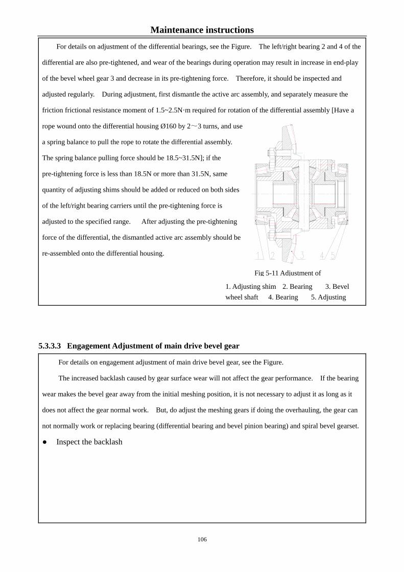
Maintenance instructions
For details on adjustment of the differential bearings, see the Figure. The left/right bearing 2 and 4 of the
differential are also pre-tightened, and wear of the bearings during operation may result in increase in end-play
of the bevel wheel gear 3 and decrease in its pre-tightening force. Therefore, it should be inspected and
adjusted regularly. During adjustment, first dismantle the active arc assembly, and separately measure the
friction frictional resistance moment of 1.5~2.5N·m required for rotation of the differential assembly [Have a
rope wound onto the differential housing Ø160 by 2~3 turns, and use
a spring balance to pull the rope to rotate the differential assembly.
The spring balance pulling force should be 18.5~31.5N]; if the
pre-tightening force is less than 18.5N or more than 31.5N, same
quantity of adjusting shims should be added or reduced on both sides
of the left/right bearing carriers until the pre-tightening force is
adjusted to the specified range. After adjusting the pre-tightening
force of the differential, the dismantled active arc assembly should be
re-assembled onto the differential housing.
5.3.3.3 Engagement Adjustment of main drive bevel gear
For details on engagement adjustment of main drive bevel gear, see the Figure.
The increased backlash caused by gear surface wear will not affect the gear performance. If the bearing
wear makes the bevel gear away from the initial meshing position, it is not necessary to adjust it as long as it
does not affect the gear normal work. But, do adjust the meshing gears if doing the overhauling, the gear can
not normally work or replacing bearing (differential bearing and bevel pinion bearing) and spiral bevel gearset.
● Inspect the backlash
1. Adjusting shim 2. Bearing 3. Bevel wheel shaft 4. Bearing 5. Adjusting
Fig 5-11 Adjustment of
106

Maintenance instructions
Insert a lead sheet into the non-working flanks of the
bevel wheel and pinion gears, respectively, and turn the gear
to squeeze the lead sheet. Then, remove the lead sheets,
and measure the sum of the thinnest thickness of the two
lead sheets (i.e. backlash). The sum of the thinnest thickness
of the two lead sheets should be 0.2~0.4mm. The
measurement should be carried out at three points on the
whole circumference of the gear, and the three measured
values should be averaged. If the meshing clearance does
not meet requirements, the adjusting shim 5 of the
differential bearing pedestal 7 can be increased or reduced.
When the clearance is big, withdraw the right shim
shown in Figure 5-11, and insert it on the left side,
vice versa.
● Check the meshing mark
Apply a layer of thin and even red lead at raised surface of the bevel wheel gear 6. At this moment, the
recessed surface of the bevel pinion shaft 4 is subject to force, so as to rotate the gear and obtain a meshing
imprint on the bevel pinion gear. Correct meshing imprint should be in the vicinity of the pitch cone at middle
part of the tooth height and slightly higher than the small end and should be at distance not less than 3 ~4mm
from the end edge, whose length should not be less than 60% the tooth length, and height should not be less
than 55% the tooth height. During adjustment, move the bevel pinion gear shaft in axial direction by changing
thickness of the adjusting shim 2, and move the bevel wheel gear in circumferential direction by changing
thickness of the adjusting shim 5. To avoid influence on pre-tightening of the differential bearing, must add
the shims removed from the side bearing pedestal into the bearing pedestal on the other side to keep total
thickness of adjusting shims for the left/right bearing pedestal unchanged.
During adjustment, when the meshing clearance is contradictory to the meshing imprint (i.e. the meshing
imprint is appropriate, and the clearance is not appropriate, or vice versa), the meshing imprint prevails, but the
meshing clearance should not be less than 0.2mm. During dismantling, inspection and adjustment, pay
attention to position and quantity of the adjusting shims; after the adjustment is finished, store the dismantled
remaining shims for future use.
Fig. 5-12 Engagement Adjustment of
1. Blot 2. Adjusting shim 3. Front bearing pedestal 4. Bevel pinion shaft 5. Adjusting shim 6. Bevel wheel shaft 7. Differential bearing pedestal
107

Maintenance instructions
5.3.4 Adjustment of Final Drive
For adjustment of the final drive of the front drive axle, see the figure. The 2 conical roller bearings 7 of
the final drive of the front drive axle are pre-tightened. During inspection and adjustment, first dismantle the
bolt 1, remove the planetary carrier 2, tighten the adjusting nut 3, and then turn the nut back by 1/10~1/6 turn to
enable the front wheel hub to rotate flexibly, and finally re-assemble and tighten the dismantled parts.The
clearance G between the planetary carrier 6 and bearing 1 is equal to 0.075~0.125mm. During assembling of
the tractor, the clearance has been adjusted, so that no adjustment is carried out during operation. However,
adjustment should be carried out during overhaul or when replacing the planetary gear mechanism.
Fig. 5-13 Adjustment of Final Drive
1. Bearing 2. Washer 3. Bolt 4. Planetary carrier pressure plate 5. Stop washer 6. Planetary carrier
During adjustment, use a padding tool to support the planetary carrier assembly and pressure plate 4, so
that the end surface of the planetary carrier pressure plate is firmly against the end surface of the planetary
carrier, and measure the distance A from the end surface of the planetary carrier pressure plate 4 to the end
surface of the planetary carrier 6; then, measure the depth B from the end surface of the drive shaft and bearing
1, so that thickness δ of the adjusting shim 2 is equal to A-B+(0.075~0.125) mm. When inserting adjusting
shims, the adjusting shims should be arranged from the thicker shim to thinner shim, and the number of
adjusting shims should be minimized. Place the selected adjusting shim 2 at the position shown at the figure,
and align the planetary carrier assembly with the drive shaft spline, and have it installed onto the shaft; then,
tighten the mounting bolt 3 of the planetary carrier pressure plate, and use a stop washer 5 to lock it.
5.3.5 Adjustment of front wheel hub bearing
108

Maintenance instructions
Normal clearance between the front wheel hub
bearings of the FOTON-TD Series two-wheel drive
tractor models is 0.05~0.15mm. Due to bearing
wear during operation, the clearance increases
gradually; when the clearance exceeds 0.4mm, it
should be adjusted accordingly. During adjustment,
use a jack to support the front axle to enable the front
wheels to be above ground, so as to remove the screw
2, bearing cover 3 and cotter pin 4 in sequence,
and screw in the adjusting nut 5 until the bearing
clearance is eliminated, and then turn the nut
back by 1/30~1/10 turn. At this moment, the front wheels should be able to rotate flexibly. Then, insert the
cotter pin 4 and install the bearing cover 3.
5.3.6 Adjustment of front drive axle (4WD tractor)
5.3.6.1 Adjustment of central drive of the front drive axle
For adjustment of the central drive of the front drive
axle, see the figure.
Both the two tapered roller bearings on the bevel
pinion shaft of the front drive axle and the two tapered
roller bearings on the differential case are preloaded.
When in use, due to bearing’s wear, an axial clearance
appears between the bevel pinion shaft and the
differential case. Be sure to check it for every 1600h.
Bevel pinion shaft bearing is adjusted by the adjusting
nut1. When adjusting, firstly tighten the nut 1 and
return it back by 1/10~1/6 circle. At last lock the
nut. As to the adjustment of differential housing
bearing, the left and right helicoidal should be
adjusted simultaneously to keep the meshing
clearance between the main drive bevel gearset
within (0.15~0.3)mm. Use the locking sheet to lock the adjusting helicoidal. The detection method for the
backlash and contact pattern is the same as that of the central transmission of the rear axle.
1. Adjusting nut; 2. Tapered roller bearing; 3.
Bevel pinion shaft; .4. Adjusting shim; 5. Bevel
wheel gear 6. Adjusting ring; 7. Locking plate;
8. Blot
Fig 5-15 Adjustment of central drive of the
Fig. 5-14 Adjustment of front wheel hub
1. Oil cup; 2. Screw; 3. Bearing cover; 4.
Cotter pin; 5. Adjusting nut; 6. Bearing
109

Maintenance instructions
5.3.6.2 Adjusting the final drive of the front drive axle
For adjustment of the final drive of the front drive
axle, see the figure. The 2 conical roller bearings 7 of the
final drive of the front drive axle are pre-tightened.
During inspection and adjustment, first dismantle the bolt
1, remove the planetary carrier 2, tighten the adjusting nut
3, and then turn the nut back by 1/10~1/6 turn to enable
the front wheel hub to rotate flexibly, and finally
re-assemble and tighten the dismantled parts.
Fig 5-16 Adjusting the final drive of the front drive axle
5.4 Adjustment of hydraulic suspension system
5.4.1 Adjustment of lifter
1. Bolt; 2. Planetary carrier; 3. Adjusting nut;
4. Drive shaft; 5. Sun wheel; 6. Front wheel
hub; 7. Tapered roller bearing
110

Maintenance instructions
Fig. 5-17 Adjustment of lifter 1. Connecting link; 2. Outer lift arm; 3. Middle arm; 4. Adjusting threaded sleeve; 5. Nut; 6. Control lever; 7. Descent speed control handle 8. Sleeve ; 9. Hollow bolt
During delivery of the tractor, the lifter has
been adjusted properly, and no adjustment by the
user is required. However, due to wear of the
drive pairs of the lever parts and looseness of the
fasteners, the original adjustment status of the lifter
is impaired, resulting in abnormal operation of the
lifter, or when assembling the lifter after being
repaired, the lifter should be adjusted. The lifter
is adjusted by following method and sequence (See
Figure 5-17):
● Pull the distributor control handle 6 to
the lowest down position and keep it standstill.
● Start the engine, and slowly move the
control handle 6 toward the up position.
At this moment, the external lifting arm 2 is
moved toward the lifting direction constantly.
● If the control handle 6 is moved to the highest lifting position, but the external lifting arm 2 does not
reach the highest position, it is required to adjust the threaded sleeve 4 to enlarge the distance between the
distributor feedback arm and the middle arm, so as to enable the external lifting arm to turn upward until an
angle of 60° is formed between the lifting arm and the horizontal line. Lock the nut 5, and at this moment, the
marking line of the external lifting arm is in line with that of the lifter case. Lift the lifter up and down for 3
times; if the lifter operates normally, the adjustment is finished.
● If the control handle 6 does not move to the highest position, but the external lifting arm 2 has
reached the highest position, it is required to adjust the adjusting threaded sleeve 4 to reduce the distance
between feedback arm and the middle arm. When the control handle 6 is moved to the highest position and the
external lifting arm 2 reaches the highest position, tighten the locknut 5. Lift the lifter up and down for 3 times;
if the lifter operates normally, the adjustment is finished.
Important: When an implement with a power take-off is required, it is required that the implement be
lifted above the ground and the lifting height having no influence on steering of the tractor in the field be
guaranteed, for the purpose of preventing excessive lifting height of the implement resulting in damage to
the drive shaft that is connected from the PTO shaft to the implement.
111

Maintenance instructions
5.4.2 Adjustment of the distributor
5.4.2.1 Inspect travel of the lowering valve
● Unscrew the lowering valve plug 8;
● Set the control handle (See Figure 5-17, No. 6) at
the highest ascending position (i.e. the control valve is placed
at ascending position), and measure the distance H1 from the
steel ball 6 to the upper end surface of the lowering valve
pocket 2;
● Set the control handle at the descending position
(i.e. the main control valve is placed at descending position),
and measure the distance H2 from the steel ball 6 to the upper
end surface of the lowering valve pocket 2;
● In case of H1- H2=(2±0.2)mm, it
indicates that it is adjusted properly. Otherwise,
the adjustment dimension can be obtained by
adding or reducing the adjusting shim 6.
● Tighten the lowering valve plug.
5.4.2.2 Adjusting the safety valve of the distributor
Note:
1. The safety valve of the distributor has been adjusted properly during delivery, and the user does
not need to conduct adjustment; if required to adjust it, the adjustment must be carried out on a test
table;
2. Opening pressure of the safety valve of the distributor is 17.5~18 MPa;
3. The distributor is a precision part, and usually, no dismantling is allowed; if the distributor must
be dismantled, it should be dismantled at a clean place, and cleaned with clean gasoline or kerosene.
Fig. 5-18 Adjustment of the distributor
1. Swing rod; 2. Lowering valve pocket ; 3. Main control valve; 4. Push pin; 5. Adjusting shim; 6.Steel ball; 7. Lowering valve; 8. Lowering valve plug
112
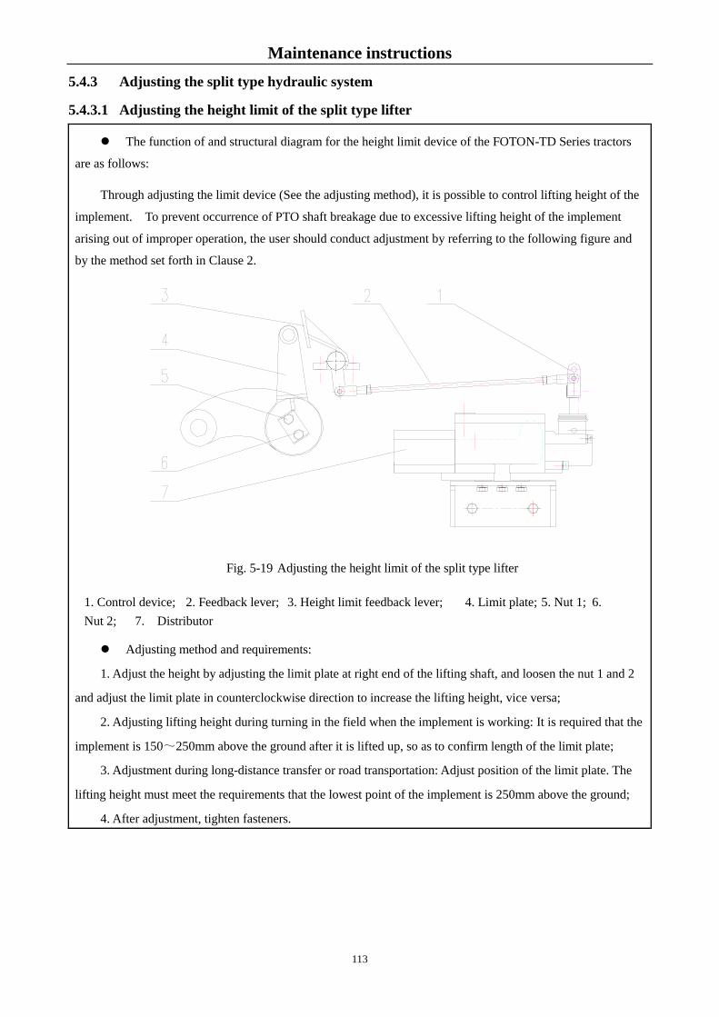
Maintenance instructions 5.4.3 Adjusting the split type hydraulic system
5.4.3.1 Adjusting the height limit of the split type lifter
The function of and structural diagram for the height limit device of the FOTON-TD Series tractors
are as follows:
Through adjusting the limit device (See the adjusting method), it is possible to control lifting height of the
implement. To prevent occurrence of PTO shaft breakage due to excessive lifting height of the implement
arising out of improper operation, the user should conduct adjustment by referring to the following figure and
by the method set forth in Clause 2.
Fig. 5-19 Adjusting the height limit of the split type lifter
Adjusting method and requirements:
1. Adjust the height by adjusting the limit plate at right end of the lifting shaft, and loosen the nut 1 and 2
and adjust the limit plate in counterclockwise direction to increase the lifting height, vice versa;
2. Adjusting lifting height during turning in the field when the implement is working: It is required that the
implement is 150~250mm above the ground after it is lifted up, so as to confirm length of the limit plate;
3. Adjustment during long-distance transfer or road transportation: Adjust position of the limit plate. The
lifting height must meet the requirements that the lowest point of the implement is 250mm above the ground;
4. After adjustment, tighten fasteners.
1. Control device; 2. Feedback lever; 3. Height limit feedback lever; 4. Limit plate; 5. Nut 1; 6. Nut 2; 7. Distributor
113

Maintenance instructions
5.4.3.2 Adjusting the oil cylinder of the split type lifter
Fig. 5-20 Adjusting the oil cylinder of the split type lifter
To ensure safety and reliability during transportation of the implement, the positioning clamp should be
adjusted to press the positioning valve 9 to the limit position when the implement is lifted up to the highest
point. Through the positioning valve, the oil line of the lower chamber of the oil cylinder is closed so that it
cannot be lowered any more.
5.4.4.3 Adjusting lowering height of the oil cylinder
The lowering height is controlled by the positioning valve and positioning
clamp stop block on the oil cylinder. The positioning clamp stop block can be
adjusted upward or downward on the piston rod. The lower the positioning clamp
stop block is, the smaller the lowering height is, vice versa. In the lowering
process, the oil cylinder stops lowering when the positioning clamp stop block
presses the positioning valve.
Fig. 5-21 Oil cylinder assembly
1. Positioning clamp stop block; 2. Positioning valve
1. Lower cover; 2. Cylinder body; 3.Piston rod; 4. Upper cover; 5. Wing nut; 6. Piston rod
connecting fork; 7. Positioning clamp; 8. Positioning valve; 9. Piston
114

Maintenance instructions
5.5 Precautions for use of full hydraulic steering system
FOTON-TD Series tractors adopt a full hydraulic steering system. The structure of the full hydraulic
steering gear is as follows. The steering system has been adjusted properly in the factory. Attention should be
paid to the following matters during the course of using:
● Frequently inspect the joint of
each screw thread which shall be tightened if it
is loose. Make sure there is no leak at any
joint when the full hydraulic steering system
is operating.
● Frequently check the level in the
oil reservoir, add it if necessary.
● If the steering is found to be
turning heavily or out of order,
it is required to carefully find the cause.
It is not allowed to pull the steering wheel
blindly or simply disassemble the steering gear in case of the part damage. Turning the steering wheel with two
people is strictly prohibited.
● Ensure that the steering gear is in the same axle with the steering axle and the clearance shall exist in the
axial during the installation of the full hydraulic steering system. Inspect whether the steering wheel can be
returned flexibly after installation.
● Ensure the oil is clean. For this purpose, it is required to frequently inspect the filter element and the oil in
the filter. Inspection method: Drop one drop of the oil on the blotting paper, then if a black center is found in
the oil stains, the oil shall be replaced.
● The gas in the fuel cylinder shall be exhausted after replacing with new engine oil. Exhausting method:
Loosen the steering cylinder bolt head and let the oil pump run at low speed to bleed the air until no bubbles
appear in the effluent oil.
Disassemble the connection between the piston rod of the steering fuel cylinder and the steering wheel, turn
the steering wheel to make the piston reach the left end or right end (Never stop in the two extreme positions),
and then add oil to the highest level.
Tighten all threaded connection (do not tighten it under pressure condition). Connect the piston. Check
the steering system for normal work at all kinds of working state.
Fig. 5-22 Full hydraulic steering gear 1. Cross-shaped connecting plate; 2. Front cover; 3. Valve body; 4. Leaf spring; 5. Pin; 6. Valve pocket; 7. Valve spool; 8. Universal driving shaft; 9. Rotor; 10. Rear cover; 11. Spacing plate; 12. Stator; 13. O-ring; 14. steel ball; 15. O-ring; 16. X-ring; 17. O-ring
Important: When adjusting the distance between the positioning clamp stop block and the positioning
valve, must keep consistency in adjustment of the two oil cylinders, with deviation of 0~0.5mm.
115

Maintenance instructions
Important:
1. Before delivery, a safe overflow pressure of the overflow valve for the constant-flow overflow
pump has been adjusted, and cannot be dismantled for adjustment, so as to avoid operation of the
system;
2. The constant-flow overflow pump is a precision part, and is usually cannot be dismantled, usually;
it should be dismantled at a clean place, and washed with clean gasoline or kerosene.
116
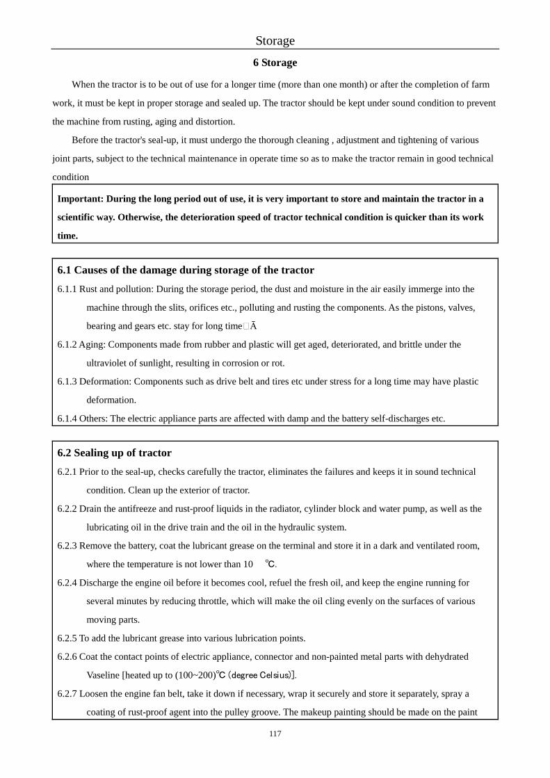
Storage 6 Storage
When the tractor is to be out of use for a longer time (more than one month) or after the completion of farm
work, it must be kept in proper storage and sealed up. The tractor should be kept under sound condition to prevent
the machine from rusting, aging and distortion.
Before the tractor's seal-up, it must undergo the thorough cleaning , adjustment and tightening of various
joint parts, subject to the technical maintenance in operate time so as to make the tractor remain in good technical
condition
Important: During the long period out of use, it is very important to store and maintain the tractor in a
scientific way. Otherwise, the deterioration speed of tractor technical condition is quicker than its work
time.
6.1 Causes of the damage during storage of the tractor
6.1.1 Rust and pollution: During the storage period, the dust and moisture in the air easily immerge into the
machine through the slits, orifices etc., polluting and rusting the components. As the pistons, valves,
bearing and gears etc. stay for long time�Ā
6.1.2 Aging: Components made from rubber and plastic will get aged, deteriorated, and brittle under the
ultraviolet of sunlight, resulting in corrosion or rot.
6.1.3 Deformation: Components such as drive belt and tires etc under stress for a long time may have plastic
deformation.
6.1.4 Others: The electric appliance parts are affected with damp and the battery self-discharges etc.
6.2 Sealing up of tractor
6.2.1 Prior to the seal-up, checks carefully the tractor, eliminates the failures and keeps it in sound technical
condition. Clean up the exterior of tractor.
6.2.2 Drain the antifreeze and rust-proof liquids in the radiator, cylinder block and water pump, as well as the
lubricating oil in the drive train and the oil in the hydraulic system.
6.2.3 Remove the battery, coat the lubricant grease on the terminal and store it in a dark and ventilated room,
where the temperature is not lower than 10 ℃.
6.2.4 Discharge the engine oil before it becomes cool, refuel the fresh oil, and keep the engine running for
several minutes by reducing throttle, which will make the oil cling evenly on the surfaces of various
moving parts.
6.2.5 To add the lubricant grease into various lubrication points.
6.2.6 Coat the contact points of electric appliance, connector and non-painted metal parts with dehydrated
Vaseline [heated up to (100~200)℃ (degree Celsius)].
6.2.7 Loosen the engine fan belt, take it down if necessary, wrap it securely and store it separately, spray a
coating of rust-proof agent into the pulley groove. The makeup painting should be made on the paint
117
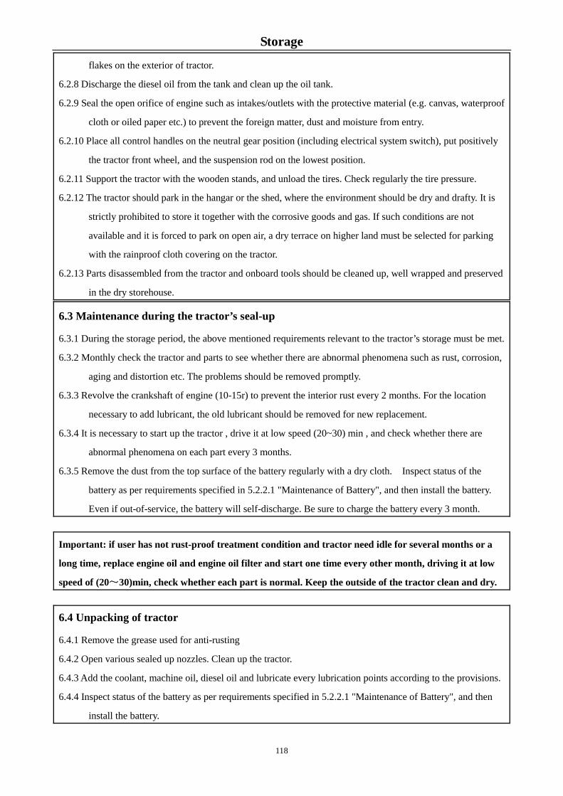
Storage
flakes on the exterior of tractor.
6.2.8 Discharge the diesel oil from the tank and clean up the oil tank.
6.2.9 Seal the open orifice of engine such as intakes/outlets with the protective material (e.g. canvas, waterproof
cloth or oiled paper etc.) to prevent the foreign matter, dust and moisture from entry.
6.2.10 Place all control handles on the neutral gear position (including electrical system switch), put positively
the tractor front wheel, and the suspension rod on the lowest position.
6.2.11 Support the tractor with the wooden stands, and unload the tires. Check regularly the tire pressure.
6.2.12 The tractor should park in the hangar or the shed, where the environment should be dry and drafty. It is
strictly prohibited to store it together with the corrosive goods and gas. If such conditions are not
available and it is forced to park on open air, a dry terrace on higher land must be selected for parking
with the rainproof cloth covering on the tractor.
6.2.13 Parts disassembled from the tractor and onboard tools should be cleaned up, well wrapped and preserved
in the dry storehouse. 6.3 Maintenance during the tractor’s seal-up
6.3.1 During the storage period, the above mentioned requirements relevant to the tractor’s storage must be met.
6.3.2 Monthly check the tractor and parts to see whether there are abnormal phenomena such as rust, corrosion,
aging and distortion etc. The problems should be removed promptly.
6.3.3 Revolve the crankshaft of engine (10-15r) to prevent the interior rust every 2 months. For the location
necessary to add lubricant, the old lubricant should be removed for new replacement.
6.3.4 It is necessary to start up the tractor , drive it at low speed (20~30) min , and check whether there are
abnormal phenomena on each part every 3 months.
6.3.5 Remove the dust from the top surface of the battery regularly with a dry cloth. Inspect status of the
battery as per requirements specified in 5.2.2.1 "Maintenance of Battery", and then install the battery.
Even if out-of-service, the battery will self-discharge. Be sure to charge the battery every 3 month.
Important: if user has not rust-proof treatment condition and tractor need idle for several months or a
long time, replace engine oil and engine oil filter and start one time every other month, driving it at low
speed of (20~30)min, check whether each part is normal. Keep the outside of the tractor clean and dry.
6.4 Unpacking of tractor
6.4.1 Remove the grease used for anti-rusting
6.4.2 Open various sealed up nozzles. Clean up the tractor.
6.4.3 Add the coolant, machine oil, diesel oil and lubricate every lubrication points according to the provisions.
6.4.4 Inspect status of the battery as per requirements specified in 5.2.2.1 "Maintenance of Battery", and then
install the battery.
118

Storage
6.4.5 Remove the remainder anti-rust agent in the belt grooves of fan and installs the belt. Adjusts the
transmission belt tension according to the specification (See Operation and maintenance manual of
engine)
6.4.6 Set the battery, and coat the vaseline on the terminals.
6.4.7 Check the tightening of the circuit and pipeline.
6.4.8 Control the tractor according to the requirements of manual.
Note: Please refer to the Operation and maintenance manual of engine for details of engine's sealing and
unsesaling.
119
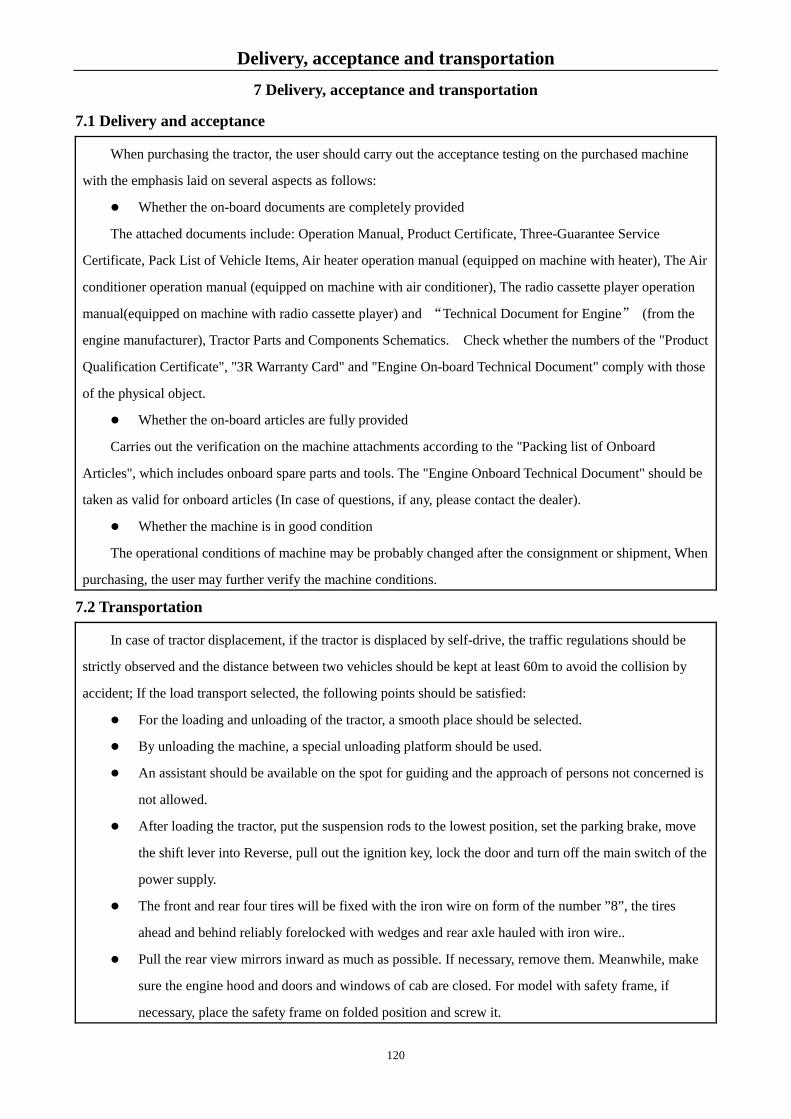
Delivery, acceptance and transportation 7 Delivery, acceptance and transportation
7.1 Delivery and acceptance
When purchasing the tractor, the user should carry out the acceptance testing on the purchased machine
with the emphasis laid on several aspects as follows:
Whether the on-board documents are completely provided
The attached documents include: Operation Manual, Product Certificate, Three-Guarantee Service
Certificate, Pack List of Vehicle Items, Air heater operation manual (equipped on machine with heater), The Air
conditioner operation manual (equipped on machine with air conditioner), The radio cassette player operation
manual(equipped on machine with radio cassette player) and “Technical Document for Engine” (from the
engine manufacturer), Tractor Parts and Components Schematics. Check whether the numbers of the "Product
Qualification Certificate", "3R Warranty Card" and "Engine On-board Technical Document" comply with those
of the physical object.
Whether the on-board articles are fully provided
Carries out the verification on the machine attachments according to the "Packing list of Onboard
Articles", which includes onboard spare parts and tools. The "Engine Onboard Technical Document" should be
taken as valid for onboard articles (In case of questions, if any, please contact the dealer).
Whether the machine is in good condition
The operational conditions of machine may be probably changed after the consignment or shipment, When
purchasing, the user may further verify the machine conditions.
7.2 Transportation
In case of tractor displacement, if the tractor is displaced by self-drive, the traffic regulations should be
strictly observed and the distance between two vehicles should be kept at least 60m to avoid the collision by
accident; If the load transport selected, the following points should be satisfied:
For the loading and unloading of the tractor, a smooth place should be selected.
By unloading the machine, a special unloading platform should be used.
An assistant should be available on the spot for guiding and the approach of persons not concerned is
not allowed.
After loading the tractor, put the suspension rods to the lowest position, set the parking brake, move
the shift lever into Reverse, pull out the ignition key, lock the door and turn off the main switch of the
power supply.
The front and rear four tires will be fixed with the iron wire on form of the number ”8”, the tires
ahead and behind reliably forelocked with wedges and rear axle hauled with iron wire..
Pull the rear view mirrors inward as much as possible. If necessary, remove them. Meanwhile, make
sure the engine hood and doors and windows of cab are closed. For model with safety frame, if
necessary, place the safety frame on folded position and screw it.
120

Delivery, acceptance and transportation
When passing tunnels and the bridges, pay attention to the load height, and slow down the speed
sufficiently while a turn is made.
While unloading, the hand brake should be first released; the drive gear should be shifted on and
slowly driven down at lowest speed.
Attentions: 1. While the tractor is loaded/unloaded, the truck-trailer should be fully braked to stop. The
front/rear wheels should be safely forelocked so as to prevent the tractor and driver from the danger of
overturn or fall-off.
2. While loading and unloading, the tractor should be driven at the lowest speed. To avoid the
tractor overturning or falling caused by high speed.
121

Technical specifications
8 Technical specifications
8.1 Product model LOVOL TD series tractor product model has the following meanings:
T D □ □ □ ○ ○
Distinctive emblem, Use a capital form of Latin letter to represent it.
Function code, None represents general agriculture mode, T represents transport mode. Model code, “0” means rear wheel drive four-wheel drive; “4” means four wheel drive. Power code, expressed by the integer around the value of engine rated power times 1.36. Series Code
The corresponding power values are as follows:
Corresponding power values to the product type:
TD750/TD754 wheeled tractor's rated power of 55 kw (75 PS)
TD800/TD804 wheeled tractor's rated power of 59 kw (80 PS)
TD820/TD824 wheeled tractor's rated power of 60.3 kw (82 PS)
TD850/TD854 wheeled tractor's rated power of 62.5 kw (85 PS)
TD900/TD904 wheeled tractor's rated power of 66.2 kw (90 PS)
TD950/TD954 wheeled tractor's rated power of 70.0 kw (95 PS)
TD1000/TD1004 wheeled tractor's rated power of 73.5 kw (100 PS)
TD1104/TD1104 wheeled tractor's rated power of 81 kw (110 PS)
Product Standard: Q/LWZ 001 LOVOL Wheeled Tractor
8.2 Product Technical Specifications Table 8-1 Main Technical Specifications of TD Series Tractor
Item Unit Technical parameter
TD750/TD800/TD820/TD850/ TD900/TD950/TD1000/TD1100
TD754/TD804/TD824/TD854/ TD904/TD954/TD1004/TD1104
Type —— 4×2 wheel type 4×4 wheel type
Rated Traction Force kN 14.6/15.5/15.8/16.3/
17.7/18.7/19.7/21.7
17.3/18.6/19/19.7/
21.3/22.5/23.7/25
PTO Shaft power kW 46.7/50.2/51.3/53.1/
56.3/59.5/62.5/68.8 46.7/50.2/51.3/53.1/ 56.3/59.5/62.5/68.8
Overall Dimensi
on
Length (Including Rear
Overhang) mm 4530(Including front
counterweight) 4530(Including front
counterweight)
Width (Common
track, outside of common
tire )
mm 1986 2050
Height (to the top of muffler)
mm 2760 2810
Wheel base mm 2195/2366 2195/2366 Track
(comm Front Wheel mm 1385~1685(Factory 1485) 1610~1950(Factory 1610/1710) ①
122

Technical specifications
Item Unit Technical parameter
TD750/TD800/TD820/TD850/ TD900/TD950/TD1000/TD1100
TD754/TD804/TD824/TD854/ TD904/TD954/TD1004/TD1104
on tire) Adjusting way of front wheel
—— Adjustable Adjustable
Rear Wheel mm 1608~1996(Factory 1608) 1608~1996(Factory 1608) Adjusting way of
rear wheel —— Adjustable or stepless Adjustable or stepless
Ground
Clearance
Min. Ground Clearance
mm 420 (Bottom of oil tank)
375 (Bottom of oil cylinder base)
405 (Lower edge of front drive axle)
Agronomic clearance
mm 495 420
Turning
radius
Unilateral brake m 3.6±0.2 4.2±0.3
4.6±0.3(Front wheel: 13.6-24)
Non-unilateral brake
m 4.0±0.2 4.9±0.3
5.2±0.3(Front wheel: 13.6-24)
Structural
Quality
Model with cab kg
3560 3915 Model without
cab 3260 3615
Min. Service Quality
Model with cab kg
3800 4155
Model without cab 3500 3855
Mass Distribution Ratio
Front axle
With cab
kg
1400 1565
Without cab 1290 1450
Rear axle
With cab 2400 2590
Without cab 2210 2405
Counterweigh
t
Front counterweight(o
ptional) kg 310 242 or 310 nor 440
Rear counterweight(o
ptional) kg 320 or 360 or 480 or 540 320 or 480
Transmission system
Clutch —— Single plate, dry-type,double-acting clutch
Gearbox ——
It is combination type 4×(2+1), i.e. 8 forward gears and 4 reverse gears; when it is installed with optional creeper gear or shuttle type gear shift mechanism, it is 4×(2+1)×2, i.e. 16 forward gears, 8 reverse gears. The main/auxiliary gearshift device adopts a straight-tooth engaging sleeve for gear shift.
Rear axle
Central transmission
—— Spiral bevel gear
Differential —— Closed, 4 planetary gears
Differential lock
—— Splined sleeve type
Rear final drive
—— Single-stage planetary gear type, exterior to both sides of the rear axle box
123

Technical specifications
Item Unit Technical parameter
TD750/TD800/TD820/TD850/ TD900/TD950/TD1000/TD1100
TD754/TD804/TD824/TD854/ TD904/TD954/TD1004/TD1104
Front drive axle
Drive Shaft —— ━━ Middle-set drive Shaft
Front central drive
—— ━━ Spiral bevel gear
Front differential
—— ━━ Closed, 2 planetary gears
Front final drive
—— ━━ Single-stage planetary gear type
Traveling
system
Rack —— Frameless Front Suspension —— Rigid suspension type ━━
Front axle —— Telescopic type ━━ Toe in of front
wheel mm 5~10 0~5
Tire pressur
e
Front Wheel kPa 200~250 150~180
Rear Wheel kPa 150~180/
120~150(11-32 Paddy)
Tire Specification
Standard: front wheel/rear wheel
—— 6.5-20/14.9-30 11.2-24/16.9-34
Optional: front wheel/rear wheel
—
7.5-20/14.9-30 6.5-20 or 7.5-20/16.9-34; 6.5-20 or 7.5-20/13.6-38; 6.5-20 or 7.5-20/18.4-30;
11.2-24/18.4-30 11.2-24/13.6-38 12.4-24/16.9-34 12.4-24/18.4-30 12.4-24/13.6-38 13.6-24/16.9-34 13.6-24/18.4-30 13.6-24/13.6-38
Steering
System
Method —— Front wheel hydraulic steering
Steering Gear —— Swing line rotary valve type full hydraulic steering gear
Brake system
Driving brake —— Wet type, disc type, hydrostatic control Parking brake —— Independent hand brake Trailer brake —— Air brake, shot-off
Working
devices
Hydraulic system type —— Open, semi-split type or split type
Hydraulic oil pump —— Semi-split type: gear pump CB-F316L;
Split type: gear pump CB-F320L or CB-F325L Distributor —— Sliding valve type
Cylinder
Diameter × stroke mm φ110×128(single acting)/φ80×200(double acting)
Form —— Single acting (semi-split type)/double acting (split type)
Suspension mechanism mm
Rear three-point linkage, type 2 Upper suspension point joint hole × width: φ25.5×51; Lower suspension point joint hole × width: φ28.7×45;
Tilling depth adjustment
method —— Semi-split Type Lifter: Force-position adjustment, floating control
or split Type Lifter: Height adjustment, floating control
124

Technical specifications
Item Unit Technical parameter
TD750/TD800/TD820/TD850/ TD900/TD950/TD1000/TD1100
TD754/TD804/TD824/TD854/ TD904/TD954/TD1004/TD1104
System max. lifting force
(610mm after suspension
point)
kN Semi-split Type: ≥15 Split Type: ≥20
Open pressure of system safety valve
MPa 17.5~18.0
Hydraulic Output
Form —— Simple hydraulic output or Multi-way valve
Quantity ——
Semi-split Type Lifter: 1-way (Simple hydraulic output) or 1 pair or 2 pairs (Multi-way valve );
Split Type Lifter:1 pair or 2 pairs (Multi-way valve ) Specific
ation —— M18×1.5
PTO shaft
Form —— Rear-mounted, independent
Specification —— φ35 6-tooth rectangular spline shaft (may select φ38 8-tooth rectangular spline shaft or φ35 21-tooth involute spline shaft)
Revolving Speed r/min 540/1000(optional 760/1000,540/760,760/850) Towin
g trailer
Towing
device
Form —— Swing rod type
Road clearance mm 367
Trailer trailer —— U-hook
Cab —— As an option which is simple and comfortable, and equipped with hot air fan, or a fan or an air conditioner.
Safety frame —— 2-pillar (model without cab ), optional
Drive seat —— Mechanical suspension type, PVC surface layer with adjustable height, forward/backward position and seat back
Electric instrument system
Electrical system type V Double wire system of 12V negative pole grounding
Generator
Model —— For details see the operation manual of engine Voltage V 14
Power kW 0.65/0.75
Electric
instrument
system
Adjuste
r
Model —— For details see the operation manual of engine Adjust voltage V 14
Start
motor
Model —— For details see the operation manual of engine Voltage V 12
Power kW 3.7
Battery
Model —— 6-QW-120 Voltage V 12 Volume A·h 120 Quantity —— 1
Lightin
g and
Headlamp V W 12V, 55/60W,combined type
Front steering
lamp
V W 12V,21W,2(model without cab)or 4(model with cab)
125

Technical specifications
Item Unit Technical parameter
TD750/TD800/TD820/TD850/ TD900/TD950/TD1000/TD1100
TD754/TD804/TD824/TD854/ TD904/TD954/TD1004/TD1104
signaling
devices
Position lamp
(front)
V W 12V,5W,2(model without cab)or 4(model with cab)
Rear combination lamp
W Position lamp (rear) 10W, steering lamp 21W, Brake lamp 21W,
reflector lamp (red) each 1piece at right and left Rear
working lamp
V W 12V,55W,2
Trailer socket —— 7-hole trailer socket, 1 piece.
Monitoring and warning
device
Combination
instrument ——
With tachometer, water temperature,oil pressure gauge, fuel gauge, 1
Warning device ——
Instrument alarm indicator lamp: Brake fault(as an option for the model with an air brake system), left/right steering indicator lamp, dipped beam indicator lamp, charging indicator lamp, warm-up indicator lamp (as an option for the model with a pre-heater), position indicator lamp, parking brake indicator lamp, brake fluid level alarm; Signal lamps and devices: Brake lamp, left/right steering lamp, front/rear position lamp, reflector lamp; Air filter blockage alarm and safety warning markings
Injection
volume
Radiator L 14 Fuel Tank L 145
Engine oil pan L According to the operation manual of engine Oil bath type air
filter L Fill the specified oil level as needed
Hydraulic steering oil L 2.5
Brake oil L 0.6 Drive drain oil L 38
Lifter oil L 18(semi-split type)/28(split type) Central
transmission of the front drive
axle
L — 6.1
Final drive of the front drive axle L — 1.2(each side)
Note: For the items marked with ①
installed, and the content after the slash is parameter when a replacement bonnet is installed.
126

Technical specifications
Table 8-2 Main Technical Specifications of TD Series Tractor Engine
Item Unit Technical parameter
Engine
Model ——
1004-4TRT
Lovol Power
1004C-P4T Lovol Power
1004C-P4TW Lovol Power
1004C-P4TA Lovol Power
1104C-P4TA Lovol Power
1004-4TWRT Lovol Power
1004-4TART Lovol Power
1004D-4TAR
T Lovol Power
1104D-44
T Britis
h Perki
ns
Emission
Standards
—— Nationa l
National Ⅱ
National Ⅱ
National Ⅱ
National Ⅱ EPA Ⅱ
EPA Ⅱ,
EuroStage Ⅱ
EPATier Ⅲ
EuroStage Ⅲ
A
EPATier Ⅲ EuroStageⅢA
Connecting
method of the engine
and transmis
sion
—— Direct connection
Type ——
Water-Coolin
g, In-line, four-str
oke
Water-Coolin
g, In-line, four-str
oke
Water inter-cooler,
In-line, four-str
oke
Air inter-cooler,
In-line, four-str
oke
Air inter-cooler,
In-line, four-str
oke
Water inter-cooler,
In-line, four-str
oke
Air inter-cooler,
In-line, four-str
oke
Air inter-cooler,
In-line, four-str
oke
Air inter-cooler
, In-lin
e, four-stroke
Number of
cylinder —— 4
Cylinder Bore × Stroke
mm 100×127
100×127
100×127
100×127
100×127
100×127
100×127
100×127
105×127
Rated power kW
55.0/60.3/66.2/70.0
55.0/59/
60.3/62.5/
66.2/70.0
73.5/81 81 81 60.3 60.3/6
6.2 60.3/6
6.2 60.3/6
6.2
Nameplate
power/speed
kW r/min
55.0/2300
60.3/2300
66.2/2300
70.0/2300
55.0/2200
59/2200
60.3/2200
62.5/2200
66.2/2200
70.0/2200
73.5/2200
81/2200
81/2200
81/2200
60.3/2300
69/2300
74/2300
69/2200 74/220
0
68/2300
72/2300
Rated Speed r/min 2300 2200 2200 2200 2200 2300 2300 2200 2300
127

Technical specifications
Item Unit Technical parameter
Max Torque/ RPM
N·m/ (r/min
)
≥263/1500~1700(TD750/TD754) ≥335/1500~1700 (TD800/TD804) ≥288/1500~1700 (TD820/TD824) ≥340/1500~1700 (TD850/TD854) ≥350/1500~1700 (TD900/TD904) ≥360/1500~1700 (TD950/TD954) ≥380/1500~1700 (TD1000/TD1004) ≥404/1500~1700 ( 1004C-P4TW ) /1400~1600
(1104C-P4TA/1004C-P4TA)(TD1100/TD1104) Fuel
Consumption Rate under Rated
Working Conditio
n
g/kW· h ≤260
Rated Working Conditio
n Oil Consum
ption Rate
g/kW ·h ≤2.1
Lubricating way Pressure type Starting method Electric starting Air filter type Dry type or wet type
Cooling system type Water-Cooling, Water inter-cooler, Air inter-cooler
128

Technical specifications
Table 8-3 Theoretical speed of LOVOL-TD series tractor (I)
Unit: km/h
Model TD750/TD800/TD820/TD850/TD900/TD950/TD1000/TD1100 TD754/TD804/TD824/TD854/TD904/TD954/TD1004/TD1104
Gear 16F+8R(creeper gear)- rear tire16.9-34 or 14.9-30(2WD
Tractor)
16F+8R(Shuttle gearshift)- rear tire16.9-34 or 14.9-30(2WD
Tractor)
Direction
High/low shift
Auxiliary
gearshift
Main gearshift
For
war
d
gea
r
Low
shift
Slow
shift
1 0.4/0.5 1.5/1.6
2 0.7/0.7 2.0/2.1
3 1.1/1.2 2.6/2.7
4 1.5/1.6 5.1/5.3
Fast
shift
1 1.9/2.0 2.2/2.3
2 3.0/3.1 3.0/3.1
3 4.8/5.0 3.9/4.0
4 6.7/7.0 7.5/7.9
High
shift
Slow
shift
1 2.2/2.3 6.5/6.8
2 3.4/3.6 8.6/9.0
3 5.5/5.8 11.2/11.7
4 7.7/8.0 21.8/22.8
Fast
shift
1 9.6/10.0 9.6/10.0
2 14.9/15.6 12.8/13.4
3 23.9/25.0 16.6/17.3
4 33.3/34.9 32.2/33.7
Reverse gea
r
Low shift
Reverse gear
1 0.6/0.6 2.3/2.4 2 0.9/1.0 3.1/3.2 3 1.5/1.6 4.0/4.2 4 2.1/2.2 7.7/8.1
High shift
Reverse gear
1 3.0/3.1 9.9/10.3 2 4.6/4.8 13.1/13.7 3 7.4/7.7 17.1/17.8 4 10.3/10.8 33.2/34.7
129
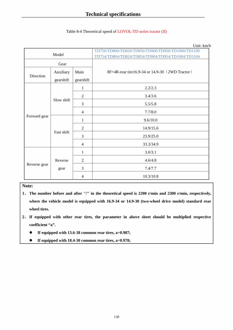
Technical specifications
Table 8-4 Theoretical speed of LOVOL-TD series tractor (II)
Unit: km/h
Model TD750/TD800/TD820/TD850/TD900/TD950/TD1000/TD1100 TD754/TD804/TD824/TD854/TD904/TD954/TD1004/TD1104
Gear
8F+4R-rear tire16.9-34 or 14.9-30(2WD Tractor) Direction
Auxiliary
gearshift
Main
gearshift
Forward gear
Slow shift
1 2.2/2.3
2 3.4/3.6
3 5.5/5.8
4 7.7/8.0
Fast shift
1 9.6/10.0
2 14.9/15.6
3 23.9/25.0
4 33.3/34.9
Reverse gear Reverse
gear
1 3.0/3.1
2 4.6/4.8
3 7.4/7.7
4 10.3/10.8
Note: 1、 The number before and after "/" in the theoretical speed is 2200 r/min and 2300 r/min, respectively,
where the vehicle model is equipped with 16.9-34 or 14.9-30 (two-wheel drive model) standard rear
wheel tires.
2、 If equipped with other rear tires, the parameter in above sheet should be multiplied respective
coefficient “a”.
If equipped with 13.6-38 common rear tires, a=0.987;
If equipped with 18.4-30 common rear tires, a=0.978;
130

Disassembly and disposal 9 Disassembly and disposal
After the machine reaches its due service life, for your personal safety and the protection of social environment, please deliver it to the licensed recycling company specialized in disassembly. When disassembling, do it from top to bottom and from outside to inside. To disassemble a bulky or heavy object, use a special sling. The battery should be recycled by professional battery recycling company #, waste oil and so on should be treated properly. Do not reject them randomly for they may cause the pollution risk to the environment.
We kindly remind you, the improper placement will cause the personal injury on lack of special removal
tools and practical experience in disassembly and after disassembly
WARNING: The battery contains electrolyte which is highly corrosive. Do not get electrolyte in
your eyes or on your skins or clothing. If so, flush your eyes or skin with large quantities of water and go to hospital immediately to avoid accidental burns.
Important: 1. The replaced battery acid liquor cannot be disposed at any place, so as to avoid environmental pollution. 2. The used oil belongs to waste oil. To avoid environment pollution, do not discard it in a trash bin
Warning: When disassembling the large or heavy mass object, the special hoisting mechanism
must be used. Pay attention to personal safety.
131

Warranty item
10 Warranty item
10.1 Product warranty basis LOVOL-TD series wheeled tractor is covered by the warranty based on the following documents and
regulations. The liability of Repair, Replacement, Return of Agricultural Machinery, directive 126 of General
Administration of Quality Supervision, Inspection and Quarantine of P.R.C Law of the People's Republic of China on Product Quality Law of the People's Republic of China on the Protection of Consumer Rights and Interests
10.2 Cases not covered by the warranty
According to relevant laws and regulations, some conditions are excluded from the range of guarantee. For details, please refer to Chapters involved with Three-Guarantee Service Certificate.
Note: Some behaviors will possibly invalidate the warranty condition. For details, see the Warranty
Card.
Note: If the user refits the tractor or uses it for purposes other than those stipulated in the manual, it will
not be covered by the warranty scope of manufacturer, to which we kindly ask you to pay attention.
Note: 1. When user accepts warranty, he must show the Warranty Card, please keep the card properly. 2. If the machine fails, when contracting for warranty, you must inform dealer of the following
information: machine model, factory No, model and type of engine and other content on the nameplate; used time and detail description of fault.
3. Description of 3R Repair part supply year limit: ensure continued supply of products and repaired 3R parts for five years after stopping production, but delivery time of special part shall be decided after negotiation. If 3R parts are beyond the deadline,�®
4. Please use special spare parts and engine oil of product.
132

Appendix 11 Appendix
11.1 Oil and solution used on the tractor
Table 11-1 Oil and solution for tractor
Application
locations of oils
and solutions
Oils and solutions
Fuel Tank
Domestic
standard
Light diesel
oil
conforming
to GB 252
Over 20 ℃ (4~20)℃
(-5~4)℃
(-14~-5)℃
(-29~-14)℃
(-44~-29)℃
NO. 10 NO. 0 NO. -10 NO. -20 NO. -35 NO. -50
Internationa
standard
Adopt ASTM D-975 fuel oil. Under general air temperatures, use 2-D grade oil;
when ambient temperature is below 5 ℃, use 1-D grade oil.
Engine oil pan
Domestic
standard
Add oil in accordance with the Engine Manual.
Internationa
standard
Society of Automotive Engineers(SAE) viscosity classification
Use SAE10W-40 when the temperature is below -5 ℃
Above -5 ℃, use the multi-grade SAE15W-40 oil in the four seasons. Shell Rimula
R2 15W/40 diesel engine or Mobil Delvac Super 15W/40.
Quality grade should comply with API CD grade standard.
Engine radiator
If ambient temperature is 4 ℃ or more, use clean soft water for tractor cooling system.
If ambient temperature is 4 ℃ or less, use ant
If Min. ambient temperature is -15 ℃or more, adopt -25# long effective antifreeze(SH/T0521);
If Min. ambient temperature is -25℃or more, adopt-35#long effective antifreeze(SH/T0521);
If Min. ambient temperature is -35 ℃or more, adopt -45# antifreeze(SH/T0521);
If Min. ambient temperature is -45 ℃or mo -45 ℃
Bath-type air
filter
Domestic standard
Below -5 ℃: use 10w/30, above -5 ℃: use 15w/40 multi-grade oil. CC grade or CD grade in the GB 11122-2006
Internationa standard
Society of Automotive Engineers(SAE) viscosity classification Use SAE10W-40 when the temperature is below -5 ℃ Above -5 ℃: use multi-grade oil SAE15W-40. Shell Rimula R2 15W/40 diesel, Mobil Delvac 15W-40. Quality grade should comply with API CD grade standard.
Gearbox - rear
axle, hydraulic
lifter, front drive
axle
Domestic
standard
N100D drive hydraulic dual-purpose oil, executive standard: Q/LWZ B119.
Internationa
standard
MF1135 of Massey Ferguson
Or M2C 86A of Ford
133

Appendix
Application
locations of oils
and solutions
Oils and solutions
Or HY-GARDTM or J20A、J20B、J20C from John Deer
Shell Spirax S3 TLV
Steering cylinder
Domestic
standard
N100D drive hydraulic dual-purpose oil, executive standard: Q/LWZ B119.
Internationa
standard
QUATROL or other oil can be used, subject to John Deere JDMJ20A or JDMJ20B,
and the temperature is blow -40 ℃, using polar o -L-46/67.
Shell Tellus 32 hydraulic oil, Spirax S3 TLV, Mobil Nuto H32 Anti-wear hydraulic
oil.
Oil cup
Domestic
standard
General lithium base grease conforming to GB/T 7324.
Internationa
standard
SAE general purpose grease is added with 3~5% molybdenum sulfide. Use polar
region grease (MIT-G-10924C)if below -30 ℃
Institute NJGI grease D-217 with 2 viscosity grade.
Shell Gadus S2 V100 3 Lubricating grease; Mobil LUX ep 3.
Brake system
Domestic
standard
Triple-purpose oil used for drive, hydraulic and brake systems. Executive standard:
Q/LWZ B119.
Internationa
standard
SAE10W-40 engine oil
Shell Spirax S3 TLV
Windshield Used for the windshield washer. -45# anti-freezing cleaning solution (SH/T0521) should be
used at -10 ℃ temperature.
Important:
1. Drive hydraulic dual-purpose oil, diesel oil and diesel engine oil must be deposited for at least 48h
and then can be filled for use so as not to reduce cleanness to impact performance of machine.
2. When the engine is running, do not add oil into the fuel tank. If the tractor is working under the
torridity or sunlight, oil tank cannot be fully filled; once fuel runs over, wipe it immediately.
3. Do not mix oils of different brands or different manufacturers! Failure to do so can affect the
engine performance.
4. For the tractor with a heating air, the cooling system of the engine must use anti-freeze fluid in
winter, so as to avoid cracking of the heater or air conditioner.
134

Appendix 11.2 Tightening torque table for main bolt and nut
Table 11-2 Tightening torque table for main bolt and nut
Name and mounting part Thread specification Tightening torque
[N·m(Newton·meter)]
Bolt for connecting engine to gearbox
housing Stage M10-10.9
58~71
Bolt for connecting engine to gearbox
housing Stage M12-10.9
105~128
Bolt for connecting engine to gearbox
housing Stage M16-10.9
247~290
Spiralock nut for connecting gearbox to
rear axle casing Stage M12×1.5-10
130~150
Spiralock nut for connecting gearbox to
rear axle casing Stage M16×1.5-10
337~412
Nuts for coupling driven shaft housing with
rear axle housing Stage M14×1.5-8
126~154
Nuts for connecting driving wheel hub to
spoke board Stage M20×1.5-10
540~596
Nuts for connecting front wheel hub to
spoke board Stage M16×1.5-10
265~311
Connecting bolts between bracket and
engine Stage M16-10.9
247~290
Nuts for connecting steering wheel to
steering column Stage M16×1.5-8
199~243
Fastening bolts on internal and external
sleeve joints Stage M20-8.8
265~320
Bolt connecting the differential housing to
the driven arc tooth bevel gear Stage M14×1.5-8
126~154
Bolt connecting the differential housing to
the differential chamber Stage M12-8.8
73~89
Round locknut at rear end of the PTO drive
shaft
GB/T812-M48×1.5 300~350
Locknuts on rear center pinion gear shaft M50×1.5(FT800.38.207) 300~350
135

Appendix
Note: To tighten main bolts on the tractor, you must use torque wrench.
11.3 Framework oil seal
Table 11-3 Framework oil seal
Mounting position Specification Standard No. Piece/set
Transfer case bearing seat FB30×52×7D GB/T 9877.1 2
Gearbox input shaft bearing carrier FB50×72×8D GB/T 9877.1 2
PTO shaft SG60×90×12 JB2600 2
Vertical shaft of steering knuckle SD65×90×12 JB2600 8
Bearing carrier of half axle housing FB100×130×12D GB/T 9877.1 4
Intermediate support base of front axle
drive shaft
FB30×52×7D GB/T 9877.1 2
Wheel hub on front drive axle 165×190×7 5137109 2
Front drive axle shaft 40×62×12 5136002 2
Front drive fork shaft 42×62×17 5133799 2
Bevel pinion shaft of front drive axle 45×75×10 5135294 1
Kingpin hole of front drive axle
housing
56×70×7.5 5121471 2
Oil seal on the head of PTO shaft FB70×90×10D GB/T 9877.1 2
11.4 Rolling bearing
Table 11-4 Rolling bearing
Mounting position Bearing name Model Bearing
Piece/se
Gearbox input shaft bearing
Single-row radial ball
6310 GB/T 276 1
Rear end of gearbox input shaft Single-row cylindrical
20209 Special 1
Front end of auxiliary gearshift
Single-row radial ball
NUP1014 Special 1
Rear end of auxiliary gearshift
Single-row radial ball
6408N GB/T 276 1
Middle section of PTO drive
Single-row radial ball
6306 GB/T 276 1
Inner side of rear drive shaft Conical roller bearing 30214 GB/T 297 2
Outer side of rear drive shaft Conical roller bearing 30215 GB/T 297 2
Planetary wheel shaft of rear
Rolling needles 8×23.8 GB/T 309 252
Front end of PTO drive shaft Single-row radial ball
6309 GB/T 276 1
136

Appendix
Mounting position Bearing name Model Bearing
Piece/se
Rear end of PTO drive shaft Single-row radial ball
6210 GB/T 276 1
Rear end of PTO shaft Single-row radial ball
6310 GB/T 276 1
Front end of PTO shaft Single-row radial ball
6308 GB/T 276 1
Right side of differential Conical roller bearing 32216 GB/T 297 1
Left side of differential Conical roller bearing 30216 GB/T 297 1
Rear end of rear axle bevel
Conical roller bearing 32311 GB/T 297 1
Middle end of rear axle bevel
Conical roller bearing 30310 GB/T 297 1
Rear end of gearbox output shaft Single-row radial ball
6211N GB/T 276 1
Front end of gearbox output
Needle bearing K323920 JB/T 7918 1
Rear end of transmission
Single-row radial ball
6211 GB/T 276 1
Front end of transmission
Single-row radial ball
6210N GB/T 276 1
Intermediate gear shaft of
Cylindrical roller
42305E GB/T 283 2
Rear end of transfer case drive
Single-row radial ball
6306E GB/T 276 2
Middle section of front drive
Single-row radial ball
6006E GB/T 276 1
Rear end of front drive bevel
Conical roller bearing 32207 Special 1
Front end of front drive bevel
Conical roller bearing 802048 Special 1
Front drive differential Conical roller bearing 2007112E GB/T 297 2
Middle section of front drive
Single-row radial ball
6007 GB/T 297 2
Front wheel hub bearing Conical roller bearing 819310 Special 4
Planetary gear shaft of front final
Rolling needles 5×23.8 GB/T 309
Inner side of steering knuckle
Conical roller bearing 32209 GB/T 297 2
Outer side of steering knuckle Conical roller bearing 32307 GB/T 297 2
Kingpin of steering knuckle Flat-bottom thrust ball
51210 GB/T 301 2
Auxiliary clutch bearing carrier Angle contact ball
7016AC GB/T 292 1
Main clutch release bearing block Angle contact ball
996712 Special 1
Bearing carrier of steering gear
Single-row radial ball
6004 GB/T 276 1
Inner hole of drive gear for gear
Needle bearing KK64×74×41 JB/T 7918 1
Inner hole of drive gear for gear
Needle bearing KK64×74×41 JB/T 7918 1
Inner hole of drive gear for gear
Needle bearing KK64×74×41 JB/T 7918 1
Inner hole of auxiliary gearshift
Needle bearing KK55×65×43 JB/T 7918 1
Front end of PTO driven shaft Bearing 6210 GB/T 276 1 137

Appendix
Mounting position Bearing name Model Bearing
Piece/se
Rear end of PTO drive shaft Conical roller bearing 7212E GB/T 297 2
Rear end of PTO drive duplex
Conical roller bearing 7210E GB/T 297 2
11.5 Rubber O-ring
Table 11-5 Rubber O-ring
Mounting position Specification Standard No. Piece/set
Handle shaft of distributor 9.5×2.65G GB/T 3452.1 1
Feedback shaft of distributor 9.5×2.65G GB/T 3452.1 1
Interlocking shaft 13.2×1.8G GB/T 3452.1 1
Lowering valve plug of distributor 16×1.8G GB/T 3452.1 1
Safety valve of the distributor 19×2.65G GB/T 3452.1 2
Safety valve of distributor clogged 11.8×2.65G GB/T 3452.1 1
Main valve front cover of distributor 19×2.65G GB/T 3452.1 1
Descending valve of distributor 19×2.65G GB/T 3452.1 1
One-way valve of distributor 19×2.65G GB/T 3452.1 2
One-way valve plug of distributor 20×1.8G GB/T 3452.1 1
Brake pump plug 20×2.65G GB/T 3452.1 2
Oil return valve of distributor 21.2×2.65G GB/T 3452.1 1
Oil inlet of steering oil pump 19×2.65G GB/T 3452.1 1
One-way valve of distributor 25.7×2.65G GB/T 3452.1 1
Brake pump valve stem 25×3.55G GB/T 3452.1 2
Oil outlet pipe fitting of brake pump 30×3.55G GB/T 3452.1 2
Lifting shaft of lifter 54.5×5.3G(old structure)
GB/T 3452.1
Lifter piston 100×5.3G GB/T 3452.1 1
Oil inlet port of lifter cylinder head 12.5×2.65G(old structure)
GB/T 3452.1 2
Lifter cylinder head 103×3.55G(old structure)
GB/T 3452.1 1
Lifter cylinder 118×3.55G GB/T 3452.1 1
Brake piston 260×3.55G FT800.43.149 2
Brake piston 300×3.55G FT800.43.150 2
PTO control handle shaft 17×1.8G GB/T 3452.1 1
138

Appendix
Mounting position Specification Standard No. Piece/set
External casing of front axle drive
45×3.55G GB/T 3452.1 4
Transfer case control shaft 17×1.8G GB/T 3452.1 2
Bevel pinion shaft of front drive
31.5×1.8G GB/T 3452.1 1
Half shaft bearing carrier of front
80×2.62G 4966231 2
Rear mounting base of front drive
99.6×5.3G GB/T 3452.1 2
Front mounting base of front drive
52.6×3.55G GB/T 3452.1 1
Oil inlet joint of distributor 12.5×2.65G GB/T 3452.1 1
Hand brake camshaft 15×2.65G GB/T 3452.1 2
Steering axle 15×2.65G GB/T 3452.1 1
Angular pipe union of oil pump
20×2.65G GB/T 3452.1 1
Differential lock fork shaft 20×2.65G GB/T 3452.1 1
Connecting plate of oil pump inlet 21.2×2.65G GB/T 3452.1 1
Differential lock fork shaft support 30×2.65G GB/T 3452.1 1
Front axle balance pin 50×5.3G GB/T 3452.1 2
Angular pipe union of oil pump
15×2.65G GB/T 3452.1 1
Connecting plate of oil pump inlet 21.2×1.8G GB/T 3452.1 1
Mating surface between oil
26.5×2.65G GB/T 3452.1 1
Mating surface between oil
32.5×2.65G GB/T 3452.1 1
11.6 Supporting farm implements for LOVOL TD series tractor
Table 11-6 Supporting farm implements for LOVOL TD series tractor
Category
Tractor model Name of
supporting Farm implements
Agricultural machinery model
Main technical parameter
Company
Tillage
machinery
TD750/TD754 TD800/TD804 TD820/TD824 TD850/TD854
Three-share mounted plough
1L-335
Tilling depth (22~
28)cm Baoding Shuangying Agricultural Machinery Co., Ltd. Kuhn Company Besson Company
Suspension turnover three-furrow plough
1LF-335
Suspension regulating three-furrow plough
1LT-335 Tilling depth(22~
28)cm
Five-share 1L-525 Tilling depth(1~
139

Appendix
Category
Tractor model Name of
supporting Farm implements
Agricultural machinery model
Main technical parameter
Company
Tillage
machinery
mounted plough 24)cm
Six-share mounted plough
1L-627 Tilling depth(16~
20)cm
Seven-share mounted plough
1L-727 Tilling depth(16~
20)cm
Hydraulic turnover plough
1LF-430/335 Tilling depth(20~
26)cm
悬挂四铧犁 1LH-430 Tilling depth(26~
30)cm
Four-share mounted plough
1LH-338 Tilling depth(30~
35)cm
Deep-scarification and shallow-ploughing plough
1LH-435 Tilling depth30cm
Deep-scarification and shallow-ploughing plough
1FSL-435 Tilling depth(30~
35)cm
TD900/TD904
TD950/TD954 TD1000/TD1004 TD1100/TD1104
Hydraulic turnover plough
1LF-435/430 Tilling depth(22~
28)cm
Deep-scarification and shallow-ploughing plough
1FSL-435 Tilling depth(30~
35)cm
TD750/TD754 TD800/TD804
TD820/TD824 TD850/TD854
Rotary cultivator 1GQN-200/210J Tilling depth(12~
15)cm Supporting overhead tank for large-size tire
model Center height of
45-51cm
Dingzhou Dingyuan Machinery Manufacturing Co., Ltd. Xian Yaao Rotary Seeding Machine Factory
Variable speed rotary plough
1GQNB-200/230
TD900/TD904 TD950/TD954
TD1000/TD1004 TD1100/TD1104
Rotary cultivator 1GQN-200/230J
Variable speed rotary plough
1GQNB-200/230
Drive harrow DS2000 Tilling depth(12~
20)cm
Maschio (qingdao) Agricultural Machinery Co., Ltd
Scarification mac
Full series
20-disc Medium mounted harrow
1BJX-2.2 耙深(12~14)cm Jiamusi North Machinery Manufacturing Co., Ltd. 24-disc Medium 1BJBX-2.5 耙深(12~14)cm
140

Appendix
Category
Tractor model Name of
supporting Farm implements
Agricultural machinery model
Main technical parameter
Company
hinery
semi-mounted harrow
Heilongjiang Nenjiang Agricultural Machinery Factory 28-disc Medium
semi-mounted harrow
1BJBX-3.1 耙深(12~14)cm
72-disc flap type light harrow
1BY-7.2 耙深(8~10)cm
24-disc hydraulic offset heavy harrow
1BZBX-2.0/2.5 耙深(14~16)cm
Combined land preparation machine
1LZ-3.0/3.6/ 1LZ-4.2
耕深(8~10)cm
Scarification machinery
Full series
Hydraulic middle harrow
1BJ-3.4
耙深(12~14)cm Hydraulic
middle harrow 1BJ-4.0
Sow and fertilizer machinery
Full series
Fertilization and seeding machine
2BF-24A 24 wheat seeding rows
Dingzhou Dingyuan Machinery Manufacturing Co., Ltd. Heilongjiang Nenjiang Agricultural Machinery Factory Xinjiang Farming Machinery Factory Aksuli Farming Machinery Manufacture Co., Ltd
Fertilization and seeding machine
2BF-24C
Combined machine for membrane paving and seeding
2BML-12 12 cotton seeding rows
Combined machine for seeding and fertilization
2BM-8 Corn, soybean
Seeding capacity: 8 rows
Sow and fertilizer machinery
2BFXZ-24
24 wheat seeding rows Sow and fertilizer machinery
2BFXZ-24
141

Appendix
Category
Tractor model Name of
supporting Farm implements
Agricultural machinery model
Main technical parameter
Company
Air-absorbed precision seeding machine
2BQ-7/8 Corn, soybean
Seeding capacity: 7/8 rows
Spraying machine
Full series Suspension-type pesticide sprayer
3W-1200/21 Medical kit volume:
1200L Spraying width: 21m
Handan Chenggong zhong Zhibao achinery Plant
Heilongjiang Nenjiang gricultural Machinery ctory
Returnin
g machine
TD750/TD754 TD800/TD804 TD820/TD824 TD850/TD854 TD900/TD904
Straw shattering and returning machine
1JH-165/172 Working width: 1.8 m/1.72 m
Dingzhou Dingyuan Machinery Manufacturing Co., Ltd.
Shijiazhuang Agricultural Machinery Co., Ltd. Dezhou Huabei Agricultural Equipment Co., Ltd.
1JH-180/185
Working width: 1.8 m/2.0m
Stubble height (2~8)cm
TD950/TD954 TD1000/TD1004 TD1100/TD1104
Duplex
implement
TD750/TD754 TD800/TD804 TD820/TD824 TD850/TD854
Stubble ploughing rotary ridge repression machine
SGTN-200/210 Three-ridge straw
cutting and three-ridge preparation; large-tire
model: center height of tank up to 450-510
mm
Dingzhou Dingyuan Machinery Manufacturing Co., Ltd.
Shenyang Huayuan Agricultural Machinery Co., Ltd.
TD900/TD904 TD950/TD954
TD1000/TD1004 TD1100/TD1104
SGTN-210/240
TD950/TD954 TD1000/TD1004 TD1100/TD1104
Stubble ploughing ridge repression machine
STGN-240/210
Three/four-ridge straw cutting and
three/four-ridge preparation; large-tire
model: center height of tank up to 450-510
mm (high-tank model)
Harvest machinery
Full series
Wheat backpack machine
4L-2.5
Feeding capacity: 2.5kg/s
Harvesting width: 2.2m
Shijia Zhuang Shuangjian King Guilin harvester plant
Corn backpack machine
4Y-3 Three-row cutting Yanzhou Yu Feng, Yanzhou Feng
Road
machinery
Full series Highway mixing machine
LBJ-180/200 Operating width 1.8
m/2.0m
Shandong yanzhou road machinery research institute
142

Appendix
Category
Tractor model Name of
supporting Farm implements
Agricultural machinery model
Main technical parameter
Company
Trailer
Full series
Farm trailer 7C-7
Dead weight capacity 7t
Qingdao Yakai achinery Factory
He Nan Jin Da Chuan achinery Co., Ltd
Farm trailer 7C-7 Hydraulic side-discharge trailer
7CC-7
Attention: before using matching farm machinery, operator shall carefully read "Operation and Maintenance Manual" for agricultural machinery. Familiar with structure, performance, operating method, proper matching so as not to damage agricultural implement and personal accidents.
Important:
1. Before selecting agricultural machinery, refer to the reference list of operating condition of
operating area (soil resistance, agriculture requirement) and first select the category of matching
agricultural machinery and consult the dealer.
2. In accordance with the model of purchased tractor (watt level), combining with operating
condition of operating area (soil resistance, agriculture requirement), refer to the advisory opinion and
determine the main technical parameter of agricultural maፉፉ If matching is not proper, the machine
may be adversely affected.
3. Under different operating conditions (soil resistance, agriculture requirement), the working
performance and effect of the same machine is different. The user should determine the operating speed,
operating width and etc. according to the local geographical conditions.
143

Dear users,
Thank you for your patronage and welcome to select and use LOVOL-TD series wheeled tractor. We’d
like to provide you with wholehearted service and solve your problems during tractor application timely and
effectively to fulfill your demand to the greatest extent and provide excellent customer service.
We currently send the ” Users Information Feedback” with operation manual to you, and please fill in it
with regular script, then send it to the Information Center of farming business department, LOVOL Heavy
Industry Co., Ltd. in 192 North South Road, Fangzi district, Weifang City, Shandong Province, postal code:
261206. Our Company will input your Users Information Feedback into the computer to conveniently carry
out the "3 Guarantees" service for you.
We sincerely appreciate your coordination and vigorous support!
User Information Feedback Form Product model
Factory No. of Tractor
Engine Manufacturer
Engine Number
Date of Manufacture
Date of Purchase
User's Name Age Degree of Education
Driving Years
Home Address
Telephone Number Postal Code
Main Use for Purchase of
Machine Tractor Load
Time and Cause of
Fault
Name and Condition of
Damaged Parts
144

Improvement Opinion and Suggestion
Note: This feedback shall be filled in by the machine owner (or machine operator) with
true information so as to understand the service condition of the tractor and provide
great service for users. Copy of this user information feedback sheet is accepted.
145

Delivery training sheet –tractor
Tractor delivery training sheet
* Machine model
*VIN * Engine serial number
Country Dealer name
Owner information
*Name of Contact Person
* Tel. of Contact
Person
Industry type
* Contact person address
* Delivery date * Name of the delivery clerk
Evaluation (tick □ with “√” )
□Satisfied □So-so □Dissatisfied * Signature by the
user
Delivery training items
After receiving the training, customer shall master the knowledge below (tick the item with “√” for confirmation) 1. introduce the complete equipment’s nameplate information and count the accompanying spare parts, tools, and technical documents, etc.
2. Inform users of the warranty application flow, requirements, and considerations
3. Introduce the complete machine’s safety operation attentions, in addition to the safety markers’ connotations
4. Introduce the oil type required by the manufacturer
5. Introduce the name, function, and mounting position of the product’s major parts
6. Introduce the tractor’s correct operation method
7. Introduce the tractor’s correct running-in method and the servicing requirements after the running-in
8. Introduce the daily tractor servicing content, method, and considerations
Attentions: 1、 Items marked with red color on the delivery training sheet shall be filled, and the information fill
ed shall be authentic. 2、 Refer to the accompanying servicing instruction for detailed training contents.
146

SN.. Item Content Ordinary
items Key
items
1 Accompanying materials
Verify the complete equipment information. ■
Count the accompanying spare parts, accompanying tools, certificate of conformity, operation instruction, and parts catalogue.
■
2 Safety
Silencer, differential lock control, PTO control handle, hydraulic control handle warning signs.
■
Warning signs at radiator, instrument desk, fender, and PTO shaft.
■
3 Product introduction
1. According to the complete equipment’s actual configuration, give a brief introduction of the complete equipment’s major parts, such as engine hood, radiator, engine, floor, protecting brace, cab, gearbox, and rear axle. 2. Give a brief introduction of the operation of air conditioning, heater, seat, electrical switch, wiper, car audio, alarm lamp, and battery, and the adjustment to protecting brace.
■
1. Operation of shuttle-type gearshift, basic transmission/splitter, 4WD, brake, clutch, PTO, differential lock, multi-way valve, lifter (ordinary, forced, and electrical), in addition to the suspension operation and considerations; 2. Operation and considerations of the instrument’s oil pressure, water temperature, recharging, rotating speed, and hour meter.
■
4 Running-in
1. Checking before the running-in: 1.1. Check the external fastener; 1.2. Check the oil level; 1.3. Check the tire pressure; 1.4. Add lubricating grease. 2. Expound the running-in time for users according to the instruction. 2.1. Engine running-in in racing (high, middle, and low speed); 2.2. PTO running-in (high and low speed); 2.3. Hydraulic system’s running-in (loading);2.4 Tractor running-in (neutral travelling and loading) 3. Cautions for running-in: Whether the engine, chassis, hydraulic system, operation system and electrical appliance are working normally, and how to deal with the faults.
■
5 Servicing after running-in
Discharge the oil when the oil temperature is relatively high (about 60 degrees Celsius), clean the drain plug, and add new oil according to needs. Replace the engine oil and fuel filter element, clear up or clean the air filter element, oil return filter element, and oil suction filter element;
■
147

Inspection after the running-in shall be performed according to the inspection steps before the running-in.
6 Regular servicing
Daily servicing: cleaning, inspection, adjustment, and tightening. Preventive servicing on a regular basis: 50h(weekly), 200h(monthly), 400h(quarterly), 800h(semiannually), and 1600h(annually). 50h servicing: clean the air filter, and check the main/assistant clutch and brake’s stroke; 200h servicing: smear lubricating grease on the frequently rotating parts, replace engine oil and filter element, and replace fuel filter element and maintain the air filter; 400h servicing: Check the chassis, front axle, and hydraulic system’s oil level, add lubricating grease, and clean the steering oil tank’s filter element ; 800h servicing: replace hydraulic oil, steering oil, and chassis oil, clean the fuel tank, and check the valve clearance and injector’s injection pressure; 1600h servicing: clean the cooling system, and replace the front axle oil and brake fluid.
■
7 Main servicing method
1. Know how to drain the oil in engine, gearbox, rear axle, transfer case, final drive, front drive axle, steering gear, and hydraulic system; 2. Give a brief introduction of the method to clear up or clean the filter element; 3. Toe-in inspection and adjustment method; 4. Brake and clutch stroke adjustment method; 5. Lubricating grease adding requirements.
■
8 Service flow After-sales flow ■
148

Compulsory warranty service sheet –tractor
Forced Assurance Service Sheet of Tractor
* Machine model
*VIN * Engine serial
number
Country Dealer name
* Name of Contact Person
* Tel. of
Contact Person Industry type
Contact person address
* Servicing date
* The complete vehicle’s
working hours (by now)
Name of the
delivery clerk
Evaluation (tick □ with
“√” ) □Satisfied □So-so □Dissatisfied
* Signature by the user
Servicing item
1. Replace the engine oil and filter element according to requirements, and clean relevant parts;
2. Replace gearbox, front axle, lifter oil according to requirements, as well as clean relevant parts;
3. Maintain the diesel engine according to "Operating and Maintenance Instructions for Diesel Engines".
4. Clean the engine cooling system according to requirements, as well as replace the coolant;
5. Check the toe-in of front wheels, and free travels of the clutch and brake. If necessary, adjust them.
6. Check and tighten all external bolts, nuts and screws.
7. Fill lubricating grease to each tractor parts according to Maintenance and Service Schedule.
1. After each servicing operation is completed, tick the blank with√ 2. Items marked with red color on the delivery training sheet shall be filled, and the information filled shall be authentic. 3. Refer to the accompanying servicing instruction for detailed training contents.
149

Sales Tel: Sales Fax: Service Hotline: Tel: (for spare parts) Fax: (for spare parts) Postal Code: 261206 Website: http://www.fotonlovol.com E—mail: [email protected] Address: No.192, South Beihai Road, Fangzi
District,Weifang, Shandong
150


![FOTON brochure I [v5] - ESAesamultimedia.esa.int/docs/foton/FOTON-M3_brochure.pdf · The Foton-M3 spacecraft will be carrying a European payload of 400 kg covering experiments in](https://img.dokumen.tips/doc/110x75/5bcd298909d3f2c65e8c75ec/foton-brochure-i-v5-the-foton-m3-spacecraft-will-be-carrying-a-european.jpg)