Embed Size (px)
Citation preview

KC Printing Machine (Group)Limited 1-20
Website: Http://www.dg-padprinter.com Online contact Skype: yingsuhuakelven QQ: 726986799 Whatapp: 0086-13592766499 Email:[email protected] [email protected]
Operation Manual KC Printing Machine (Group) Limited
SZD-1021Auto Multi-color
Screen Printing Machine

KC Printing Machine (Group)Limited 2-20
Website: Http://www.dg-padprinter.com Online contact Skype: yingsuhuakelven QQ: 726986799 Whatapp: 0086-13592766499 Email:[email protected] [email protected]
Content
1. Precautions for safety……….…………………………………………………………….….P.3
1-1 Physical safety…………………………………………………………………………P.3
1-2 Safety over the machine…………………………………………………………....…P.3
2. Application and specification……………………………………………….…………….…P.4
2-1 Application…………………………………………………………………………...…P.4
2-2 Specification……………..………………………………………………….…….……P.4
3. Installation and adjustment………………………………………………………………..…P.5
3-1 Installation……………………………………………………………………..………P.5
3-2 Adjustment (Figure) ………………………………………………………………….P.6
⑴ Adjustment of the transmission swing angle…………………………………....P.6
⑵ Adjustment of the screen print swing angle………………………………….….P.6
⑶ Adjustment of the bottle transmission………………………………………...….P.7
⑷ Printing positioning…………………………………………………………….…..P.7
⑸ Flame treatment……………………………………………………………………P.7
4. Main control board and controlling parts ……………..……………………………….P.8
4-1 Introduction of the functions of the main control board………………………...P.8-9
4-2 Operation instructions of the touch screen…………………………………….....P.10-17
5. Operation instructions………………………………………………………………….…P.18
6. Maintenance and repairing…………………….…………………………………………P.19
6-1 Mechanical maintenance (1)……………………………………………….….…. P.19
6-2 Mechanical maintenance (2)……………………………………………..…….… P.19
7. Electric diagram…………..……………………………………………………………...…P.27
8. Pneumatic diagram………………………………………………………………….….…P.28-33
9. Diagram of electric controlling layout…………………………………………………P34--35

KC Printing Machine (Group)Limited 3-20
Website: Http://www.dg-padprinter.com Online contact Skype: yingsuhuakelven QQ: 726986799 Whatapp: 0086-13592766499 Email:[email protected] [email protected]
1. Safety Precautions
Safety Precautions:
Special attention shall be paid to the mechanical and personal safety as listed below:
1.1 Personal safety
1. Protection of eyes
(1) When the UV lamp is on, the machine cover shall not be opened. Wear UV safety mask when necessary so
as to prevent the eyes from being hurt by the ultraviolet radiation.
(2) When setting up the machine, the UV lamp shall not be turned on, unless necessary.
(3)Other people close to the machine shall be informed not to watch the ultraviolet lamp tube inside the machine
if they are not wearing the safety mask.
2. Protection of skin
The same precautions as mentioned above shall be kept in mind: The exposed skin shall not get close to the light
so as to prevent the skin from being burned by the ultraviolet radiation.
3. Protection from toxic gases
(1) Keep the working place well ventilated.
(2) No solvent with oxide shall be placed in the working area. If any, it shall be removed away from the place as the
toxic gases may be created when some oxides are radiated by the ultraviolet.
4. Protection from electric shock
(1) The coating of the cables shall be regularly checked to see if there is any damage because the electric shock
from the exposed conductor can cause deaths and other severe accidents. If the cables have been damaged,
the machine shall not be powered on. The damaged cables shall be replaced before the machine can be
powered on again upon safety check.
1-2 Mechanical safety
1. Prevention from being hurt by the machine
When the machine is running for printing, hands shall not be put inside the machine, particularly to the
running parts, so as to avoid being hurt. If the machine needs to be adjusted, the emergency stop
switch shall be first pressed to prevent the operator from being injured.
(1) Each time before start-up, the voltage of the power supply, the compressed air, the petroleum gas,
including the electric circuit and conveying conduits, shall be checked to make sure that they are
under normal conditions. Then machine can be turned on.
(2) Please don’t use the objects like sticks to insert into the machine, including the control box, feeding
machine, main and auxiliary printing units, etc. (particularly the cover of the UV part shall not be
opened randomly). Nor use the improper methods like using the hammer or crow to strike the machine
or pull, smash or pry the parts of the machine. If so, some parts of the machine may be deformed or
damaged, which can affect the printing effects, or even make the machine not work any more.
(3)The inside of the machine box shall be kept clean and no oil stain shall be attached in it. If there is any oil
stain, the cleaning agent shall be used to remove them. Never use the chemically strong solvent.
Otherwise, the machine may be damaged.
KC Printing Machine (Group)Limited 4-20
Website: Http://www.dg-padprinter.com Online contact Skype: yingsuhuakelven QQ: 726986799 Whatapp: 0086-13592766499 Email:[email protected] [email protected]
2. Application and Specification
2-1 Application
This printing machine is specially used for printing different patterns on the objects with round shape or oval
shape. As it is made up of several individual units to form a printing chain, it can be used for the purpose of multi-color
printing. The materials to be printed can be plastic, glass, ceramics, metal, etc.
2-2 Specification
Speed Round: 4000pcs/Hr Oval: 5000pcs/Hr
Printing size: Round: Diameter: 25-100mm Length:25-270mm
Oval: Width: 25-120mm Length:25-270mm
Compressed air: 5Bar
Liquefied petroleum gas: 1.5 Bar
Weight: *
Dimensions: Main and auxiliary unit: 1757mm*1000mm*1500mm
Auto-conveyor feeding device (optional): 3050mm*1300mm*1500mm
Auto-conveyor unload device (optional):
Power: Main and auxiliary unit 380VAC,3-PHASE; single unit: 5.6KVA
Auto-conveyor feeding device (optional): 380VAC,3-PHASE,1KVA
Auto-conveyor unload device (optional): 220VAC,1-PHASE,0.2KVA
3. Installation and adjustment
3-1 Installation
1. Wiring of the power cables
① Connect the conforming cables
to the power supply.
②Note: All the cables must comply
with the above listed
specifications
2. The compressed air and the
petroleum gas shall be
introduced from the external
side of the machine.
①The pressure of the compressed
air and the petroleum gas must
Connect with
compress air

KC Printing Machine (Group)Limited 5-20
Website: Http://www.dg-padprinter.com Online contact Skype: yingsuhuakelven QQ: 726986799 Whatapp: 0086-13592766499 Email:[email protected] [email protected]
comply with the above listed specifications (see the specifications)
②Note: Clean and water-free compressed air shall be used so as to guarantee the smooth work of the
machine. If the requirements over the compressed air are ignored, the pneumatic units may have failures
earlier than expected.
3. Adjustment
3-2 Adjustment
1) Swing angle adjustment (limited position adjustment); as shown in the picture below: first adjust the pendulum bar
on the driving shaft to enable the driven shaft swings to a 90 degree angle, 180 degree for transmission shaft.
And then make it horizontal for the pendulum bar’s left and right limits on transmission shaft. So it is with the

KC Printing Machine (Group)Limited 6-20
Website: Http://www.dg-padprinter.com Online contact Skype: yingsuhuakelven QQ: 726986799 Whatapp: 0086-13592766499 Email:[email protected] [email protected]
other half.
The squeegee mechanism can be adjusted up and down, right and left
left and right limits are horizontal (180 degree swing angle)
driving shaft pendulum bar
passive shaft pendulum bar
conveying shaft
swing angle
base board
symmetry
synchronization shaft
2) Printing swing angle adjustment: see picture below:
60 degree 90 degree 90 degree symmetry swinging
Swing
Adjust position till the printing swing angle requirement is met.
Conveyer
switch Conveyer
speed

KC Printing Machine (Group)Limited 7-20
Website: Http://www.dg-padprinter.com Online contact Skype: yingsuhuakelven QQ: 726986799 Whatapp: 0086-13592766499 Email:[email protected] [email protected]
3. Adjustment
3) Conveyor bottle adjustment
a) Adjustment done according to the shape of the bottle: run the mechanism to a limited position, clip the bottle by the
holder air cylinder (within the allow range),
adjust the two holding boards till the bottle is
held nicely, and then lock all parts tight.
(Holding board can be made independently
for bottle with special shape)
See picture below:
b) The printing unit should have its own
holding board, the requirement: box shaped,
air suction connection; the part that needs to
be silk printed need frequent adjustment.
c) The holder movement is controlled by a computer program,
various operation speed requires different movement angles; it is
adjustable on the touch screen. (When adjusting the machine, use
the Step button to control, and program is set separately)
4) Print positioning
For flat bottle, the position is based on its bottom; for a round
bottle, the positioning is much more complex: normally, a
positioning slot is set under the bottom; but some are positioned on the bottle screw or a specified point. No matter
which approach is applied, two independent suits are needed to be made, one is for pre-positioning, and the other is
for positioned printing. For pre-positioning, allow 365 degree turning to seek the position point, when in positioned
printing, requires little turning space before properly positioned, hence to ensure topping proceeds precisely.
Bottom register slot
Bottle mouth register
5) Flame treatment:
The bottle surface need flame treatment
to increase ink adhesion. To adjust the
flame, first please open air flow to suitable
current, and then release gas till suitable
current is met.
6) UV drying.
There are three levels for UV drying and
the maximum power is 4KW. Choose
proper level for UV drying according to
Flame treatment
device
Adjust the width
of conveyer
Sensor

KC Printing Machine (Group)Limited 8-20
Website: Http://www.dg-padprinter.com Online contact Skype: yingsuhuakelven QQ: 726986799 Whatapp: 0086-13592766499 Email:[email protected] [email protected]
material, thickness of ink and printing speed; you can also change its lightness through adjusting the UV lamp box.
The automatic on-off UV reflective shade is set through the touch screen. To save power and reduce temperature, the
UV power will be switched to the lowest level when the machine stops. The UV bulb should be changed regularly:
open the front board of the lamp box, release both sides of clips, take out the lamp holder, and change the bulb with a
same specification. (Do not change to other bulb with different specifications, because the light bulb may be subject to
different manufacturer.)
4. Main Control Panel and Controlling Parts
4-1 See the figure of the main and auxiliary control board
1. Step--Jog button
When the pressure of
the supplied air is normal,
the machine will run if this
button is pressed and stop
if released. The machine
will continuously run in
Step state if this button is
pressed without release.
Check to see if there is any
emergency stop.
Note: If the Machine is
developed with two or
multi-colors, the whole
machine will perform the
same functions even if just
press the button of any
auxiliary machine.
2. Start—Button for
running the machine
When press Start
Button on the touch screen, the machine will send out indicating sound and begin to run after this button is pressed.
3. STOP—stop running button
In the state of continuous running, press this button and the machine will stop after current printing cycle is
finished.
4. VACUUM—vacuum suction switch
When it is at the “ON” position, it means the power for the vacuum pump has been turned on and it will perform
the function of vacuum air suction.
When it is at the “OFF” position, it means the power for the vacuum pump has been turned off and it will stop
performing the function of vacuum air suction.
5. SPEED—Printing speed control
It is used for adjusting the running speed of the whole machine. Rotate it counter-clockwise to slower down the
点动STEP EJECTOR
顶咀 吸樽SUCTION
SPEED起动START
火焰点试FLAME TEST
调速
POWER停止STOP
电源EMARGENCY
紧急停止
STOP停止
START起动
EMARGENCY
紧急停止
火焰点试FLAME TEST
点动STEP
顶咀EJECTOR
Controlling
Panel
1
2
3
6
7
8
KC Printing Machine (Group)Limited 9-20
Website: Http://www.dg-padprinter.com Online contact Skype: yingsuhuakelven QQ: 726986799 Whatapp: 0086-13592766499 Email:[email protected] [email protected]
speed and rotate it clockwise to increase the speed.
6. EMER STOP—Emergency stop button
Press this button and the machine will stop running immediately.
7. Touch screen
The touch screen displays different information of the machine. With this touch screen, the machine can be
controlled and the settings can be altered easily. Please see the operation instructions for the details.
Note: The touch screen shall not be polluted by the corrosive liquid (like printing ink, thinner or plate washing
chemical, etc.)
8. FLAMER—Button for ignition
In the standby status, press this button and the flamer will be started up and the petroleum will be connected. This
button won’t be effective in the status of automatic running.
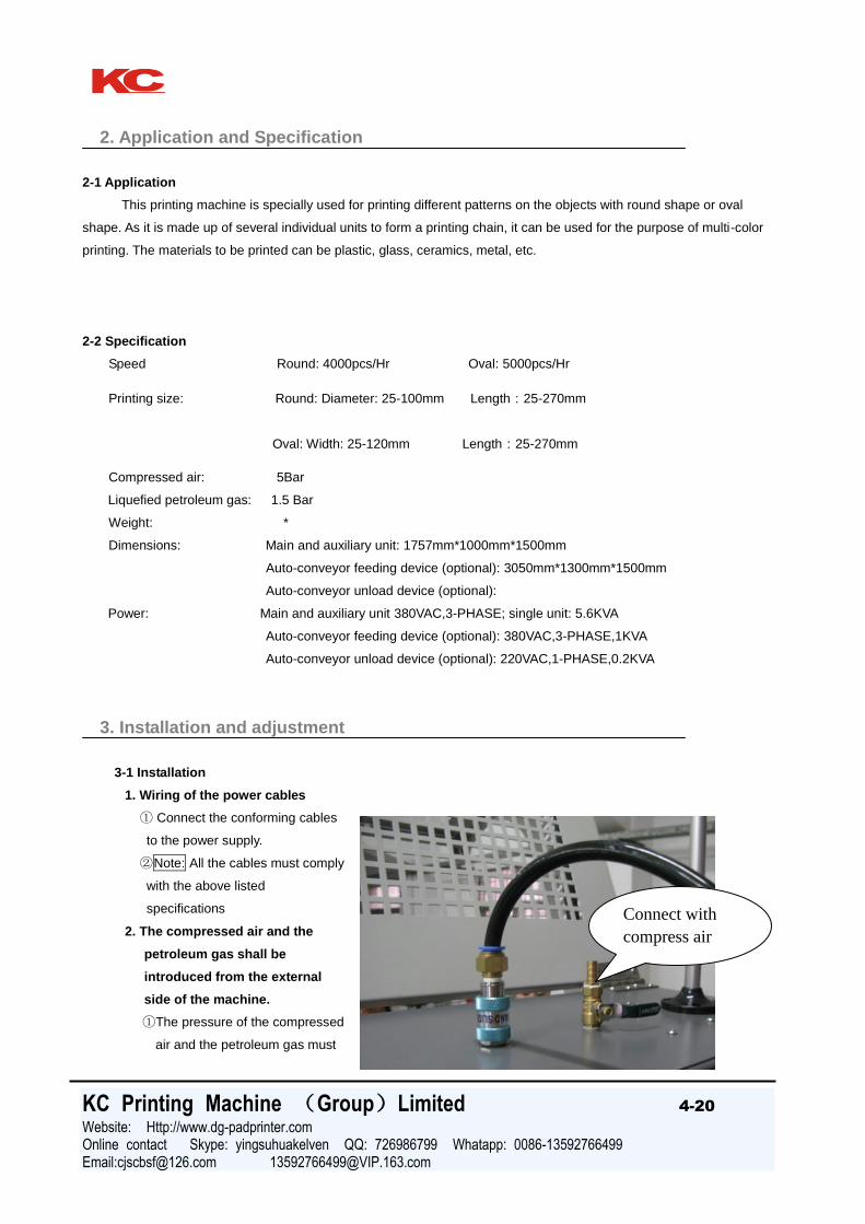
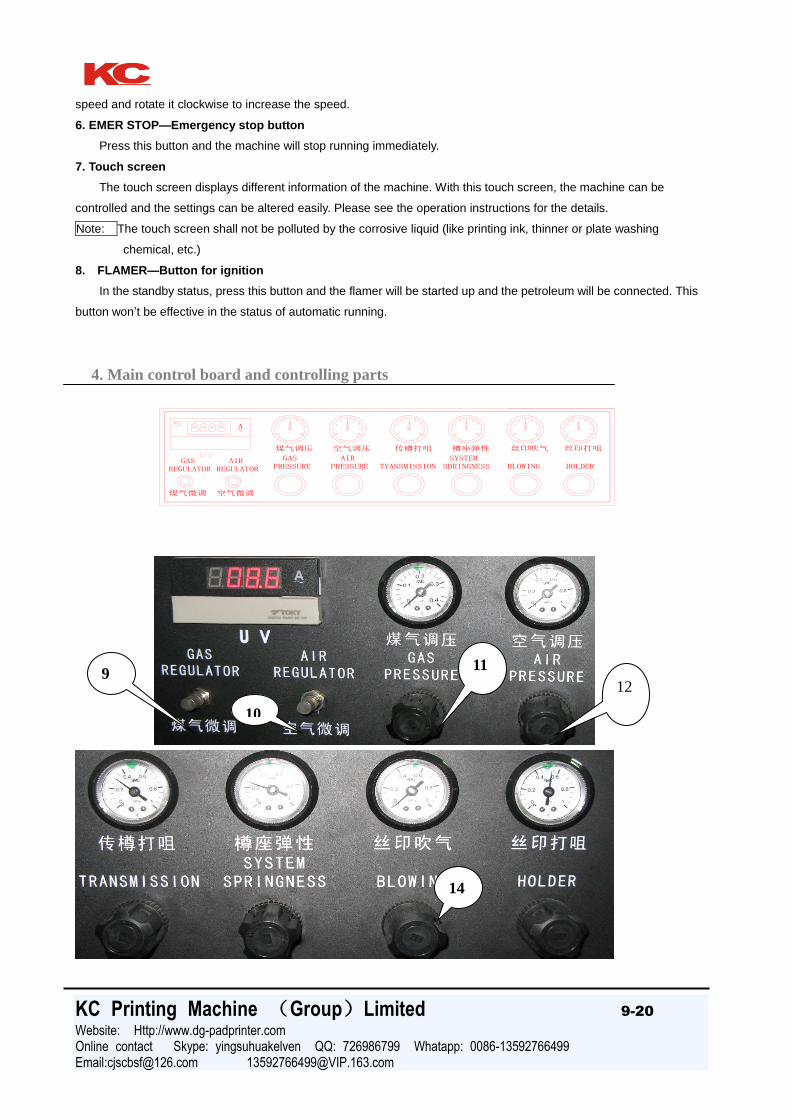
4. Main control board and controlling parts
A~
煤气微调 空气微调
REGULATOR REGULATOR
煤气调压 空气调压 传樽打咀 樽座弹性 丝印吹气 丝印打咀
GAS AIRPRESSURE
GASPRESSURE
AIRSDRINGNESS BLOWINGSYSTEM
HOLDERTYANSMISSION
9
10
11
12
14

KC Printing Machine (Group)Limited 10-20
Website: Http://www.dg-padprinter.com Online contact Skype: yingsuhuakelven QQ: 726986799 Whatapp: 0086-13592766499 Email:[email protected] [email protected]
9. GAS regulator—control valve for the flux of petroleum gas
It is used for adjusting the flux of the petroleum gas supplied to the flaming device. Rotate it counter-clockwise to
reduce the volume and rotate it clockwise to increase the volume.
10. AIR regulator-- control valve for the flux of air
It is used for adjusting the flux of air supplied to the flaming device. Rotate it counter-clockwise to reduce the
volume and rotate it clockwise to increase the volume.
11. GAS pressure—Pressure gauge of the petroleum gas and adjustment valve for the pressure
It is used for adjusting the pressure of the petroleum gas supplied to the flamer. After the cap is pulled upwards,
turn clockwise to increase the pressure and rotate it counter-clockwise to reduce the pressure.
Note: Normally, the pressure of the petroleum gas shall be adjusted to around 1.5Bar.
12. AIR pressure-- Air Pressure gauge and adjustment valve for the pressure
It is used for adjusting the pressure of the compressed air supplied to the flamer. After the cap is pulled upwards,
rotate it clockwise to increase the pressure and rotate it counter-clockwise to reduce the pressure.
Note: Normally, the pressure of the petroleum gas shall be adjusted to around 1.5Bar.
13. SQUEEGEE—Button for adjusting the pressure of the squeegee
It is used for adjusting the pressure of the squeegee to control the thickness of the ink layer. Pull the cap upwards
and rotate it clockwise to increase the pressure, and the ink layer will become thinner; rotate it counter-clockwise to
decrease the pressure, and the ink layer will become thicker. Such adjustment is necessary for the ink with different
viscosities.
14. BLOWING—Button for adjusting the blowing pressure
It is used for adjusting the blowing pressure of the top printing place. Such adjustment shall be done with the
reference of the size and thickness of the plastic bottle.
15. AMP METER—Current meter of the UV lamp
It displays the work current of the UV lamp.
16. AIR(ON/OFF)--Compressed air switch
It controls the connection and disconnection of the air source. When it is set to the “ON” position, the air source is
connected; when it is set to the “OFF” position, the air source is cut off.
17. SQUEEGEE(UP/DOWN)--Switch for the lifting and lowering down of the squeegee.
It controls the automatic lifting up and lowering down of the squeegee. When it is set to the “UP” position, the
squeegee will be automatically lifted up; when it is set to the “Down” position, the squeegee will be automatically lowered
down.
4. Main control table and controlling parts
4-2 Description of the touch screen
This machine adopts the operation-display control system composed of the advanced module type program
controller and the touch screen. The control of the machine and the setting of the parameters can be realized through
the touch screen. It is easy and simple. The controlling interfaces of the touch screen are introduced as follows:
The introduction here is the preliminary knowledge for the operation of this machine, which the operator must fully
understand. Any person who has not read this section shall not operate the machine. Particularly if the machine has

KC Printing Machine (Group)Limited 11-20
Website: Http://www.dg-padprinter.com Online contact Skype: yingsuhuakelven QQ: 726986799 Whatapp: 0086-13592766499 Email:[email protected] [email protected]
not been adjusted or set for the normal work conditions, such improper operations may bring about damages or
accidents. Thus the operations of machine shall be conducted after this Operation Manual is fully read and the related
contents like the adjustment of the machine and operation instructions are fully understood so as to avoid accidents.
The touch screen shall not be polluted by the corrosive liquid to avoid damages.
The touch screen will display the literal contents in about twenty seconds after the main electric box is electrified.
Waiting for you to turn on the POWER ON switch off
the main control table and cut off the power of the electric
cabinet. After the POWER ON switch off the main control
table is turned on, the following menu for monitoring will
be popped up:
The monitoring menu has five lines:
The first line shows the interface name, date and time
from left to right.
The second line shows the real-time angle of the main shaft,
the number of the printed quantity and running speed of the
machine from left to right.
4. Main control table and controlling
parts
The third line counter reset. Slightly press this key the
number will be cleared to 00000.
The fourth line has the Start-up key and the Turn-off
key from left to right.
In the state of one-cycle Jog running, slightly press this
key and the following will be displayed on the screen:
After the system is confirmed, slightly press the key
“NO” to return to the monitor interface. Press this key
KC
KC

KC Printing Machine (Group)Limited 12-20
Website: Http://www.dg-padprinter.com Online contact Skype: yingsuhuakelven QQ: 726986799 Whatapp: 0086-13592766499 Email:[email protected] [email protected]
slightly and the following will be displayed on the screen:
Then the UV system enters into the state of preheating (when the machine is in the state of automatic
running, start the UV system and the machine will stop running), and turn on the counter when UV is started
for working. The time of preheating is 30 seconds till the long rectangle is fully filled with black, which means
the UV system has finished the preheating and the machine can be started for normal production. Then the
interface will automatically return to the monitoring state. The fifth line of the monitoring interface has the
Maintenance and Parameter Setting Key, Slightly Pressing Maintenance Key, and its displays include the keys
of input state, output state, alarming list, records, calendar and clock, archives, directory and monitor.
4. Main control table and controlling parts
Slightly press the key of Input Status, the menu of input state will be popped up:
The round circle indicates the input status. The circle will be fully filled green when PLC has
the input signals.
Slightly press the Maintenance key to return to the maintenance menu.
Slightly press the key of Output Status to pop up the menu of output menu.
KC Printing Machine (Group)Limited 13-20
Website: Http://www.dg-padprinter.com Online contact Skype: yingsuhuakelven QQ: 726986799 Whatapp: 0086-13592766499 Email:[email protected] [email protected]
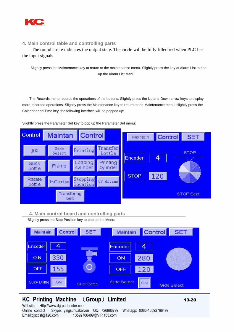
4. Main control table and controlling parts
The round circle indicates the output state. The circle will be fully filled red when PLC has
the input signals.
Slightly press the Maintenance key to return to the maintenance menu. Slightly press the key of Alarm List to pop
up the Alarm List Menu.
The Records menu records the operations of the buttons. Slightly press the Up and Down arrow keys to display
more recorded operations. Slightly press the Maintenance key to return to the Maintenance menu; slightly press the
Calendar and Time key, the following interface will be popped up:
Slightly press the Parameter Set key to pop up the Parameter Set menu:
4. Main control board and controlling parts
Slightly press the Stop Position key to pop up the Menu:
KC Printing Machine (Group)Limited 14-20
Website: Http://www.dg-padprinter.com Online contact Skype: yingsuhuakelven QQ: 726986799 Whatapp: 0086-13592766499 Email:[email protected] [email protected]
The machine is waiting for you to input the value of the stop angle by touching the numeric keyboard.
Slightly press the Parameter Setting key to pop up the Parameter Setting menu:
Slightly press the Face Selection key to pop up the Face Selection menu and set the angles
of rotating and returning.
4. Main control board and controlling parts
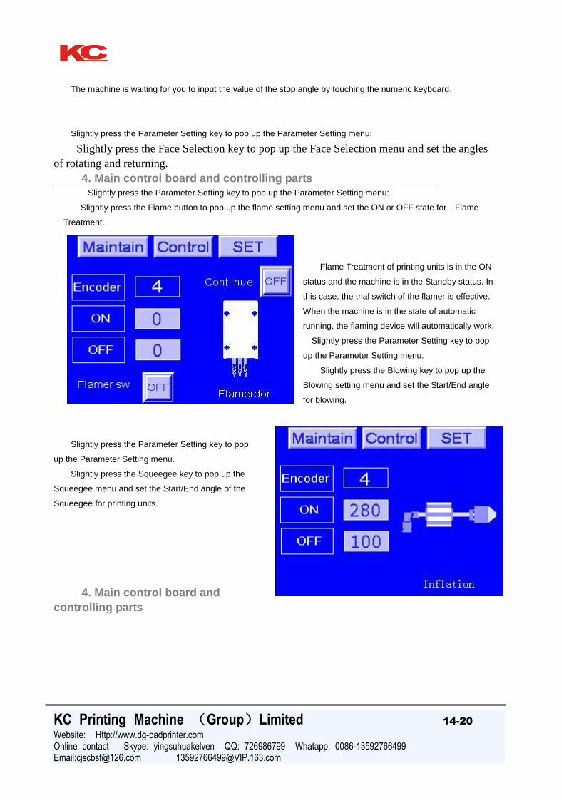
Slightly press the Parameter Setting key to pop up the Parameter Setting menu:
Slightly press the Flame button to pop up the flame setting menu and set the ON or OFF state for Flame
Treatment.
Flame Treatment of printing units is in the ON
status and the machine is in the Standby status. In
this case, the trial switch of the flamer is effective.
When the machine is in the state of automatic
running, the flaming device will automatically work.
Slightly press the Parameter Setting key to pop
up the Parameter Setting menu.
Slightly press the Blowing key to pop up the
Blowing setting menu and set the Start/End angle
for blowing.
Slightly press the Parameter Setting key to pop
up the Parameter Setting menu.
Slightly press the Squeegee key to pop up the
Squeegee menu and set the Start/End angle of the
Squeegee for printing units.
4. Main control board and
controlling parts

KC Printing Machine (Group)Limited 15-20
Website: Http://www.dg-padprinter.com Online contact Skype: yingsuhuakelven QQ: 726986799 Whatapp: 0086-13592766499 Email:[email protected] [email protected]
Set No-part No-print to the “ON” state for printing units. The squeegee won’t work until the
workpiece is available. The No-print switch of the counter (Only set Non-printing to the “ON”
state fir #1 printing unit) will detect the adjustment of distance and location, and make
adjustment according to the workpiece to be printed.
Slightly press the Parameter Setting key to pop up the Parameter Setting menu.
Slightly press the UV Drying key to pop up the Drying setting menu and set the state of UV drying for printing
units.
This menu can be used for setting the “ON” or “OFF” state of the power, “ON” or “OFF” state of the lamp shade,
the switching-over of the UV power between high, medium and low levels, UV work time and UV air-discharging. After
the UV system is normally started up for preheating, the operations of turning on or off the lamp shade and UV power
switching-over between high, medium and low levels can only be done in the state of automatic running. When in the
state of automatic running, the power of UV system can be turned on or off. If the UV system needs to be
started again, the related operations for starting up the UV system can only be done after the UV system is cooled
upon five minutes of discharging the air.
The mark indicating the OFF state of the lamp shade is the lower half of the corresponding circle, whereas the
mark indicating the ON state of the lamp shade is the upper half of the corresponding circle.
The way of indicating the high, medium and low levels of the UV power is that the corresponding

KC Printing Machine (Group)Limited 16-20
Website: Http://www.dg-padprinter.com Online contact Skype: yingsuhuakelven QQ: 726986799 Whatapp: 0086-13592766499 Email:[email protected] [email protected]
4. Main control board and controlling parts
icon is filled.
UV work time counting will record the life time of the lamp tube. The time counting shall be cleared when the lamp
tube is replaced.
The mark indicating the UV air-discharging is the corresponding icons of the exhaust fan and the clock.
Slightly press the Monitor key to pop up the Monitor menu.
Slightly press the OFF key to pop up the OFF menu for turning off the machine.
After confirming to shut off the system, slightly press the NO key to pop up the Monitor menu:
Slightly press the YES key to pop up the System-off menu:
After the UV system is shut off, wait for another five minutes till the rectangle is fully filled as the air is discharged.
5. Operation instructions
5-1. Operation instructions
The basic operations depicted in this section are suitable for the machine which has been
properly adjusted and set and is ready for printing. In order to avoid accidents, please don’t
operate the machine if it has not been adjusted and set for related items. The operator shall read
this Manual carefully before the operations. Particularly, Section of “4. Main Control Table and
Controlling Parts” shall be fully understood.

KC Printing Machine (Group)Limited 17-20
Website: Http://www.dg-padprinter.com Online contact Skype: yingsuhuakelven QQ: 726986799 Whatapp: 0086-13592766499 Email:[email protected] [email protected]
Start-up
①Turn on the switch for the main power in the power distribution cabinet and make sure everything is normal.
Then turn on the POWER ON switch for the main control. The green indicator of the work power will be on. In this case,
the operator can check the information of the electronic terminal (Touch screen) and alter the settings if necessary.
②After the work power is turned on, the operator can press the Step button for trial running so as to check the
work conditions of different parts of the machine.
③Slightly press the main ON key on the touch
screen, turn on the UV power to start up the UV
system. The touch screen will display the
preheating process of the UV lamp.
④After the UV lamp is preheated,
press the key RUN. The machine will
send out a long sound and the green lamp
in the tower lamp at the left top of the
main unit will be on. Then the machine
starts running.
Normal stop
Press the STOP key on the main control board,
the machine will stop after one printing cycle is
finished. At the same time, the yellow lamp in the tower lamp will be on. Then turn off the flaming device, close the
UV shade and set all the in-use UV lamps to the LOW level as the standby state.
Emergency stop
Press the switch of EMER.STOP, the machine will stop
running immediately. . At the same time, the yellow lamp in
the tower lamp will be on. Then turn off the flaming
device, close the UV shade and set all the in-use UV lamps
to the LOW level as the standby state.
Note: Release the emergency stop switch and turn on the
START key (both the main control table and the touch screen
have one), then the machine will keep its previous running.
Turn off
If the machine needs to be turned off after the printing is
finished, the operator can press the OFF switch on the touch screen so as to first stop the feeding. After the printing of
the workpiece which has entered into the machine is finished, the machine will automatically stop running. Then the
UV lamp will be off and the exhaust fan begins to work. In the final stage, first turn off the work power, then turn off the
power switch in the main control box and turn off the compressed air and gas. After this, all the operation procedures of
turning off the machine have been completed.
6. Maintenance
6-1 Mechanical maintenance (1)
The maintenance of machine covers many aspects of management. The following are only the basic
Fixture
Squeege
e
Switch of
screen
frame

KC Printing Machine (Group)Limited 18-20
Website: Http://www.dg-padprinter.com Online contact Skype: yingsuhuakelven QQ: 726986799 Whatapp: 0086-13592766499 Email:[email protected] [email protected]
requirements needed for the normal running of the machine. For other aspects of maintenance, such as the cleaning
of the inside of the machine, external surface of the machine, peripheral working place and the ambient environment,
shall be done be means of related regulations stipulated thereabout to achieve standard management.
6-2. Mechanical maintenance(2)
Daily maintenance
Everyday when the machine is started
up, running, or before it is turned off, the
operator shall watch on or listen to the
machine to see if there is any
abnormality. If the running is abnormal,
or if the abnormal sound is heard, the
operator shall immediately check the
machine to see if there is any
mechanical failure. If the abnormality is
caused by improper lubricating, the
transmission parts like the slide shaft,
rotating joint, ball bearing shall be
checked and more grease shall be
added.
Monthly maintenance When the machine works
till the end of the month, the operator shall check the moving joint
parts and add more grease. If the grease becomes solidified, the
solidified grease shall be removed and the related place shall be
cleaned with gasoline. Then add the new grease.
Half-year maintenance Normally, the
maintenance shall be done once every half a year. In this case,
the operator shall check the moving joint parts to see if there is
any rust, wearing, solidification of the grease, etc. If any, relevant
measures shall be taken timely to deal with it.
Annual maintenance When the machine has
run for one year, the operator shall check the machine in whole,
including each mechanical part, to see if there is any rust, wearing,
solidification of the grease, etc. If any, relevant measures shall be
taken timely to deal with it.
UV temperature
controlling
system
Present
temperature
Setting
temperature
Printing
Stroke
adjustment

KC Printing Machine (Group)Limited 19-20
Website: Http://www.dg-padprinter.com Online contact Skype: yingsuhuakelven QQ: 726986799 Whatapp: 0086-13592766499 Email:[email protected] [email protected]
If there is any question, please contact the local distributors.
Circuit Diagram of 102 Full-auto Multi-color Screen Printing Machine
Gas pressure regulating
Air pressure regulating
Transparent tube
Gas
Feeding suction cup
Swinging holder
Lamp Shade Cylinder
Squeegee and ink flooding blade
Solenoids
Air supply
Pressure switch
System springness
Blowing
Holder
Transmission
Air tank
Circuit Control Diagram-1 of 102
Full-auto Multi-color Screen Printing
Production Line
Frequency converter
#1 Main motor
#2 Main motor
#1 Lighting
#2 Lighting
Feeding motor
#1 Gas valve
#2 Gas valve
Heat emission fan:
Circuit Control Diagram-2 of 102 Full-auto
Multi-color Screen Printing Production Line
Black wire Igniter
Red wire High voltage wire
Water-removi
ng Valve
Adjust the
width of
transport
device
Adjust the
height of
UV
system

KC Printing Machine (Group)Limited 20-20
Website: Http://www.dg-padprinter.com Online contact Skype: yingsuhuakelven QQ: 726986799 Whatapp: 0086-13592766499 Email:[email protected] [email protected]
Circuit Control Diagram-5 of MS102 Full-auto Multi-color Screen Printing Production Line
Mutual inductor Vacuum pump Exhaust fan
Heat emission fan
Circuit Control
Diagram-6 of MS102
Full-auto Multi-color
Screen Printing
Production Line
Mutual inductor
Vacuum pump
Exhaust fan
Heat emission fan
Circuit Distributing
Diagram-61of MS102
Full-auto Multi-color
Screen Printing
Production Line
Circuit Distributing Diagram-2 of MS102 Full-auto Multi-color Screen Printing Production Line
Adjust according to bottle
length
Adjust according to
bottle length
Adjust the height
of fixture
Adjust according
to bottle height
Replace the plate when
changing another larger bottle