Embed Size (px)
Citation preview
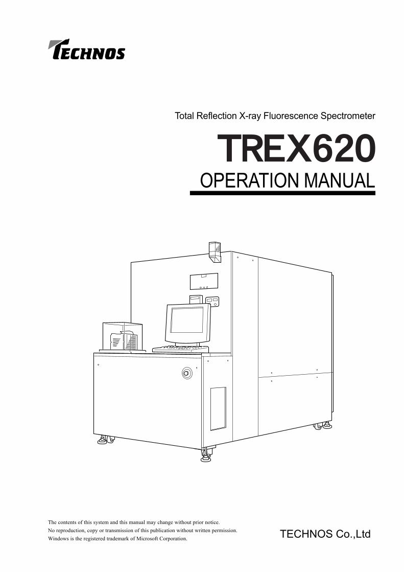
OPERATION MANUAL
Total Reflection X-ray Fluorescence Spectrometer
The contents of this system and this manual may change without prior notice.No reproduction, copy or transmission of this publication without written permission.Windows is the registered trademark of Microsoft Corporation. TECHNOS Co.,Ltd

CONTENTSTREX620
PREFACE ...................................................................... 11 Safety Notices ........................................................................ 1
Electric Shock Prevention, X-ray Exposure Prevention and General Instructions ...... 1Cautions about Liquid Nitrogen .......................................... 2Cautions about Beryllium ................................................... 3
2 DANGER WARNING Labels .................................................. 4Display Position of Danger Warning Labels ....................... 6
3 Fluorescent X-ray and Total Reflection Fluorescent X-ray Analysis ..... 7Fluorescent X-rays ............................................................. 7Total Reflection Fluorescent X-ray Analysis ....................... 7Outline of Total Reflection Fluorescent X-ray Analysis ....... 8
SPECIFICATIONS.......................................................... 91 Specifications ......................................................................... 92 Overall Configuration Diagram ............................................. 113 Vacuum System Diagram..................................................... 124 Cooling Water System Diagram ........................................... 13
PART NAMES .............................................................. 141 Main Unit .............................................................................. 142 Switch Panel ........................................................................ 153 Unit Interior .......................................................................... 164 Cooling Water, Air, Nitrogen Gas Hoses .............................. 18
HOSES......................................................................... 191 Vacuum Hoses and Cooling Water Hoses ........................... 192 Nitrogen Gas and Air Hoses ................................................ 20
UNIT STARTING AND STOPPING .............................. 211 Starting the Machine ............................................................ 21
When the unit has been off for a long time ...................... 212 Stopping the Machine .......................................................... 223 Emergency Procedure ......................................................... 224 Recovery Procedure After Emergency OFF ........................ 22
CONTENTS
CONTENTSTREX620
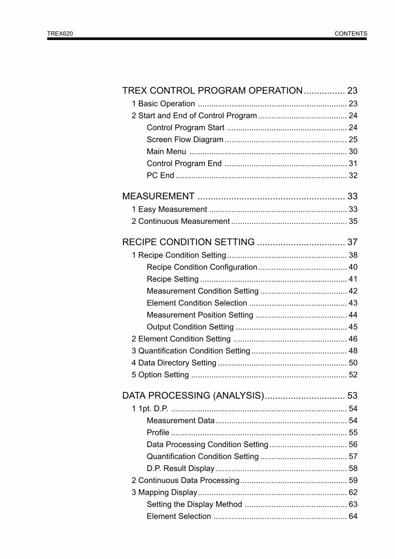
TREX CONTROL PROGRAM OPERATION................ 231 Basic Operation ................................................................... 232 Start and End of Control Program........................................ 24
Control Program Start ...................................................... 24Screen Flow Diagram ....................................................... 25Main Menu ....................................................................... 30Control Program End ....................................................... 31PC End ............................................................................. 32
MEASUREMENT ......................................................... 331 Easy Measurement .............................................................. 332 Continuous Measurement .................................................... 35
RECIPE CONDITION SETTING .................................. 371 Recipe Condition Setting...................................................... 38
Recipe Condition Configuration........................................ 40Recipe Setting .................................................................. 41Measurement Condition Setting ....................................... 42Element Condition Selection ............................................ 43Measurement Position Setting ......................................... 44Output Condition Setting .................................................. 45
2 Element Condition Setting ................................................... 463 Quantification Condition Setting ........................................... 484 Data Directory Setting .......................................................... 505 Option Setting ...................................................................... 52
DATA PROCESSING (ANALYSIS)............................... 531 1pt. D.P. ............................................................................... 54
Measurement Data ........................................................... 54Profile ............................................................................... 55Data Processing Condition Setting................................... 56Quantification Condition Setting ....................................... 57D.P. Result Display ........................................................... 58
2 Continuous Data Processing................................................ 593 Mapping Display................................................................... 62
Setting the Display Method .............................................. 63Element Selection ............................................................ 64

CONTENTSTREX620
DEVICE UTILITY ......................................................... 651 XG Setting ............................................................................ 66
Setting .............................................................................. 66Aging ................................................................................ 67
2 SC Read Setting .................................................................. 683 Initialize ................................................................................ 694 Sample Collection ................................................................ 69
ENVIRONMENT SETTING .......................................... 70Setting Enable/Disable Display of Menu Buttons ............. 71Measurment Setting ......................................................... 72
MONITOR .................................................................... 75
MEASUREMENT METHOD ......................................... 791 Set the Wafer Cassette ........................................................ 792 Measurement Execution ...................................................... 80
Easy Measurement .......................................................... 80Continuous Measurement ................................................ 81
3 Interpreting Measurement Data ........................................... 82Interpreting Measurement Data........................................ 83
X-RAY CONTROLLER ................................................. 84Alarm Display ................................................................... 85Error Display..................................................................... 85
TROUBLESHOOTING ................................................. 86Warnings .......................................................................... 91
DAILY INSPECTION AND PERIODIC INSPECTION .......... 921 Daily Inspection .................................................................... 922 Periodic Inspection ............................................................... 923 Periodic Replacement Parts ................................................ 93
CONTENTSTREX620
MAINTENANCE ........................................................... 941 Position of Unit and Sensor ................................................. 942 Adjustment Method of Sensor ,Vacuum Switch and Pressure Switches ...... 97
Optical Sensor .................................................................. 97Vacuum Switch, Pressure Switches ................................. 98
3 X-ray Tube Replacement ................................................... 100
WARRANTY ............................................................... 101
REVISION RECORD ................................................. 102
1
PREFACETREX620
PREFACEThank you for purchasing this SMIF-Compatible Total Reflection Fluorescent X-ray Wafer Surface Analysis System"Trex620"."Trex620" uses a special monochromator based on the total reflection fluorescent X-ray analysis method. It provides highsensitivity analysis of 109 atoms/cm2.For full utilization of this system's capabilities, read this manual thoroughly before using the system, and operate thesystem properly.
Safety Notices"Trex620" operation requires accurate prior safety knowledge. Observe the following instructions in order to preventpersonal injury to the operator and other persons and prevent property damage.●The following warning notices indicate the extent of the danger and damage which may occur if incorrect handling is
performed.
●Do not disassemble or modify● Disassembly or modification can cause breakdown, electric shock or radiation exposure, etc.
For internal inspection or repairs, contact the Technos Service Department.
●Stop operation if you detect signs of an abnormal condition such as a strange noise orsmell, or abnormal operation.
● Promptly stop operation and contact the Technos Service Department. Continued operation may cause a breakdown,fire or electric shock.
: This notice indicates contents which, if ignored, may result in grave danger of death orserious injury.
: This notice indicates contents which, if ignored, may possibly result in death or seriousinjury.
: This notice indicates contents which, if ignored, may possibly result in personal injury orproperty damage.
This system has built into it an X-ray generator and a high voltage generator (maximum 60 kV) to drive the X-ray genera-tor. Liquid nitrogen (boiling point –196℃) is used to cool the Solid State Detector (SSD), so handle the SSD carefully.
■ Electric Shock Prevention, X-ray Exposure Prevention and General Instructions

2
PREFACETREX620
●Do not operate the system with safety devices OFF.● If safety devices are turned OFF, the system will not stop automatically should a malfunction occur. This may cause
a breakdown, fire or electric shock.
●Avoid damage to the power cord, etc.● Do not place heavy objects on top of the power cord or intake and exhaust hoses, do not bend them, and do not place
hot appliances near them. This could cause cord damage, fire, electric shock or fluid leakage.
●Do not insert foreign objects into the interior.● Do not insert foreign objects (metal objects and easily flammable objects in particular) into the cassette elevator or
gaps in the bottom of the device, etc.This may cause a breakdown, fire or electric shock.
●Do not insert your hand inside the machine, even when the power is OFF.● Even if the power is cut off due to a malfunction, high voltage may still be operating inside the machine, so do not
insert your hand or other objects inside the machine.
●Do not leave unnecessary objects on top of the machine roof or deck.● Objects falling into the machine could cause a breakdown or fire. Falling objects can also cause an injury or damage
the machine.
●Do not clean the machine with alcohol, water or cleansers.● It could cause an electric shock, breakdown or a fire.
■ Cautions about Liquid NitrogenThe evaporation of liquid nitrogen generates a large quantity of nitrogen gas. Depending on the quantity of liquid nitrogen,it can create an oxygen deficiency, so do not discharge the liquid nitrogen indoors.The boiling point of liquid nitrogen is extremely low, –196℃. Direct contact with liquid nitrogen can cause frostbite, sotake care to avoid direct contact.
●Move out of the room if the oxygen deficiency warning sounds.● The machine's oxygen alarm indicates an oxygen deficiency has occurred. Promptly move outdoors if the alarm
sounds.
●Avoid direct contact with liquid nitrogen.● Direct contact with liquid nitrogen can cause frostbite. Provide sufficient protection when handling liquid nitrogen.

3
PREFACETREX620
■ Cautions about BerylliumBeryllium is used in the X-ray tube and the X-ray window of the Solid State Detector (SSD). Beryllium is toxic to thehuman body, so be sure to observe the handling instructions in this manual.
● Do not touch the X-ray window (beryllium).● The X-ray window is made of thin beryllium metal; it is easily damaged and toxic. Do not touch it with your hands
or any other object.
● Recover pieces of the X-ray window if it breaks.● If the X-ray window breaks, recover all the pieces. The pieces are toxic, so do not touch them directly with bare
hands when you collect them.
● Contact Technos for cleaning of the X-ray window.● The X-ray window is easily damaged, so contact Technos if you need a dirty window cleaned.
● Beryllium is a toxic waste product.● The beryllium used in the X-ray window is classified as a toxic waste product. Disposal of parts of the machine, X-
ray tube and X-ray window requires special processing. Contact Technos to provide you with correct disposal.
4
PREFACETREX620
DANGER WARNING LabelsThis system has warning labels affixed to it at locations where there are potential dangers. The danger level indicated onthe labels (DANGER, WARNING, CAUTION) is applied to situations as shown below.
Do not peel labels off or tear them. Take care that objects are not left in front of labels so that the labels are obscured fromclear view.
This notice indicates contents which, if ignored, may result ingrave danger of death or serious injury.
This notice indicates contents which, if ignored, may possiblyresult in death or serious injury.
This notice indicates contents which, if ignored, may possiblyresult in personal injury or property damage.
The warning labels show a symbol indicating the type of potential danger, the extent of the danger, and the details of thedanger.
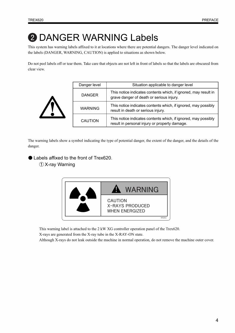
● Labels affixed to the front of Trex620.① X-ray Warning
This warning label is attached to the 2 kW XG controller operation panel of the Trex620.X-rays are generated from the X-ray tube in the X-RAY-ON state.Although X-rays do not leak outside the machine in normal operation, do not remove the machine outer cover.
Danger level Situation applicable to danger level
DANGER
WARNING
CAUTION

5
PREFACETREX620
② Laser Warning
Infrared laser is used for the wafer aligner inside the machine.Although the cover around the wafer aligner unit is constructed so that laser light does not leak outside the machine,and the operator is not exposed to laser rays during normal operation, do not remove the machine outer cover.
③ Oxygen Deficiency Warning
This system uses liquid nitrogen and nitrogen gas.If leakage of the liquid nitrogen or nitrogen gas occurs, there is danger of the nitrogen causing oxygen deficiency.If a gas leak is discovered, or the oxygen concentration meter activates the alarm, promptly take shelter outside theroom.
④ Low Temperature Burns Warning
This system uses liquid nitrogen.Liquid nitrogen is a liquid with an extremely boiling temperature of –196℃. Direct contact can cause frostbite.Do not add liquid nitrogen by hand. Using a liquid nitrogen production machine (maker recommended option) isrecommended.
6
PREFACETREX620
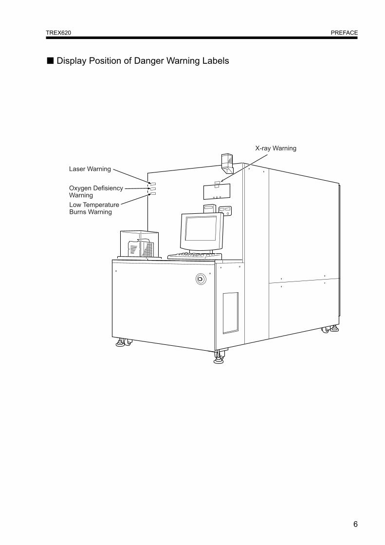
■ Display Position of Danger Warning Labels
7
PREFACETREX620
Fluorescent X-ray and Total ReflectionFluorescent X-ray Analysis
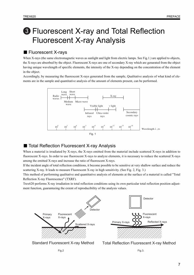
■ Fluorescent X-raysWhen X-rays (the same electromagnetic waves as sunlight and light from electric lamps. See Fig.1.) are applied to objects,the X-rays are absorbed by the object. Fluorescent X-rays are one of secondary X-ray which are genarated from the objecthaving unique wavelength of specific elements, the intensity of the X-ray depending on the concentration of the elementin the object.Accordingly, by measuring the fluorescent X-rays generated from the sample, Qualitative analysis of what kind of ele-ments are in the sample and quantitative analysis of the amount of elements present, can be performed.
■ Total Reflection Fluorescent X-ray AnalysisWhen a material is irradiated by X-rays, the X-rays emitted from the material include scattered X-rays in addition tofluorescent X-rays. In order to use fluorescent X-rays to analyze elements, it is necessary to reduce the scattered X-raysamong the emitted X-rays and increase the ratio of fluorescent X-rays.If the incident angle of total reflection conditions, it become possible to be sensitive at very shallow surface and reduce thescattering X-ray. It leads to measure Fluorescent X-ray in high sensitivity. (See Fig. 2, Fig. 3.)This method of performing qualitative and quantitative analysis of elements at the surface of a material is called "TotalReflection X-ray Fluorescence" (TXRF).Trex620 performs X-ray irradiation in total reflection conditions using its own particular total reflection position adjust-ment function, guaranteeing the extent of reproducibility of the analysis values.
106
103
100
10-3
10-6
10-9
10-12
10-15
10-18
Radiowaves
Visible light light
Infraredrays
Ultra-violetrays
Secondarycosmic rays
Wavelength ,
Longwave
Shortwave
X-ray
Mediumwave
Micro wave

8
PREFACETREX620
■ Outline of Total Reflection Fluorescent X-ray AnalysisTotal reflection fluorescent X-ray analysis involves measuring an unknown sample and the analysis can be divided intoqualitative analysis of which elements are in the test material, and quantitative analysis of the amount of the elementspresent. Another function is calibration, which checks the status of the measuring machine itself.
Trex620 is designed so that the above analysis can be performed efficiently and accurately by providing uniformity of themeasurement conditions, element conditions and output conditions.

9
SPECIFICATIONSTREX620
SPECIFICATIONSSpecifications
< Technos Standard Specifications >
10
SPECIFICATIONSTREX620

11
SPECIFICATIONSTREX620
Overall Configuration Diagram
12
SPECIFICATIONSTREX620
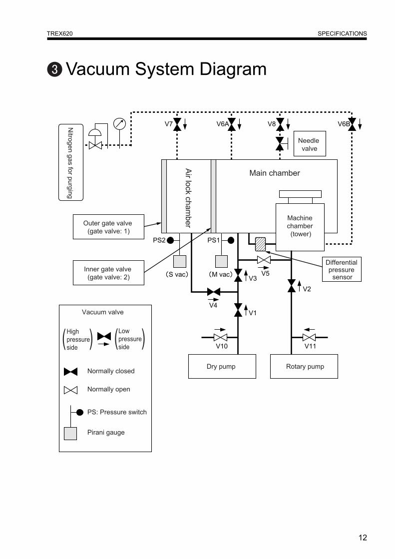
Vacuum System Diagram

13
SPECIFICATIONSTREX620
Cooling Water System Diagram
14
PART NAMESTREX620
PART NAMESMain Unit
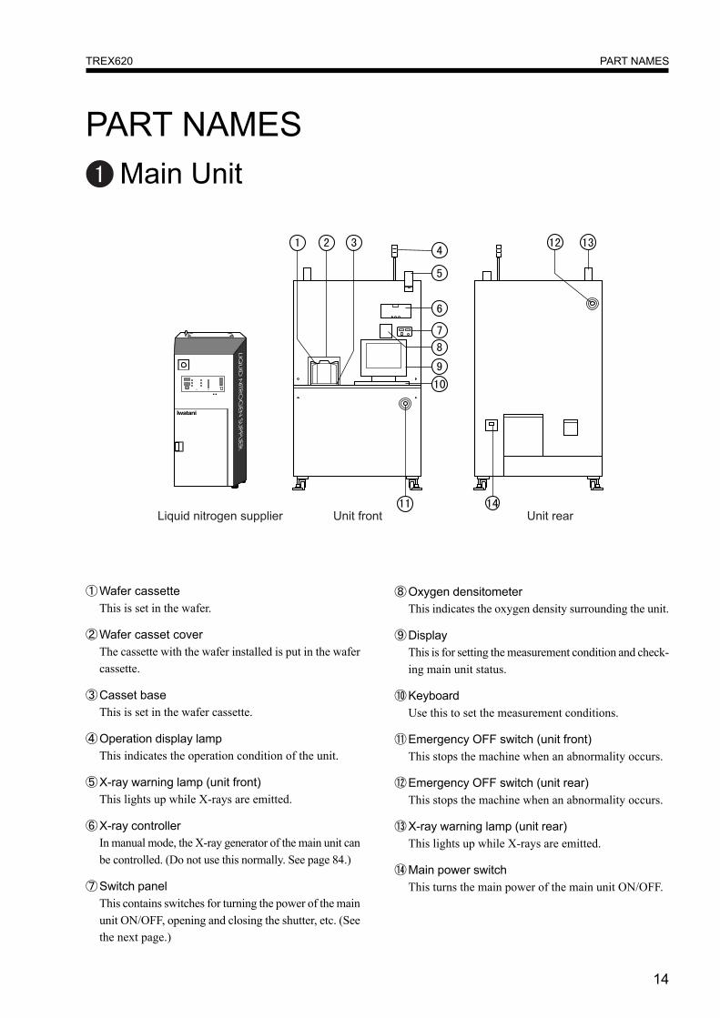
①Wafer cassetteThis is set in the wafer.
②Wafer casset coverThe cassette with the wafer installed is put in the wafercassette.
③Casset baseThis is set in the wafer cassette.
④Operation display lampThis indicates the operation condition of the unit.
⑤X-ray warning lamp (unit front)This lights up while X-rays are emitted.
⑥X-ray controllerIn manual mode, the X-ray generator of the main unit canbe controlled. (Do not use this normally. See page 84.)
⑦Switch panelThis contains switches for turning the power of the mainunit ON/OFF, opening and closing the shutter, etc. (Seethe next page.)
⑧Oxygen densitometerThis indicates the oxygen density surrounding the unit.
⑨DisplayThis is for setting the measurement condition and check-ing main unit status.
⑩KeyboardUse this to set the measurement conditions.
⑪Emergency OFF switch (unit front)This stops the machine when an abnormality occurs.
⑫Emergency OFF switch (unit rear)This stops the machine when an abnormality occurs.
⑬X-ray warning lamp (unit rear)This lights up while X-rays are emitted.
⑭Main power switchThis turns the main power of the main unit ON/OFF.

15
PART NAMESTREX620
Switch Panel
①POWER ON switchThis turns the power ON.
② POWER OFF switchThis turns the power OFF.
③SHUTTER OPEN switchThis opens the X-ray shutter.
④SHUTTER CLOSE switchThis closes the X-ray shutter.
⑤X-RAY DISABLE/ENABLE switchThis switch sets whether or not it is possible to emit X-rays.ENABLE : PossibleDISABLE : Not possible
⑥VACUUM ON switchThis turns the vacuum ON.
⑦VACUUM OFF switchThis turns the vacuum OFF.

16
PART NAMESTREX620
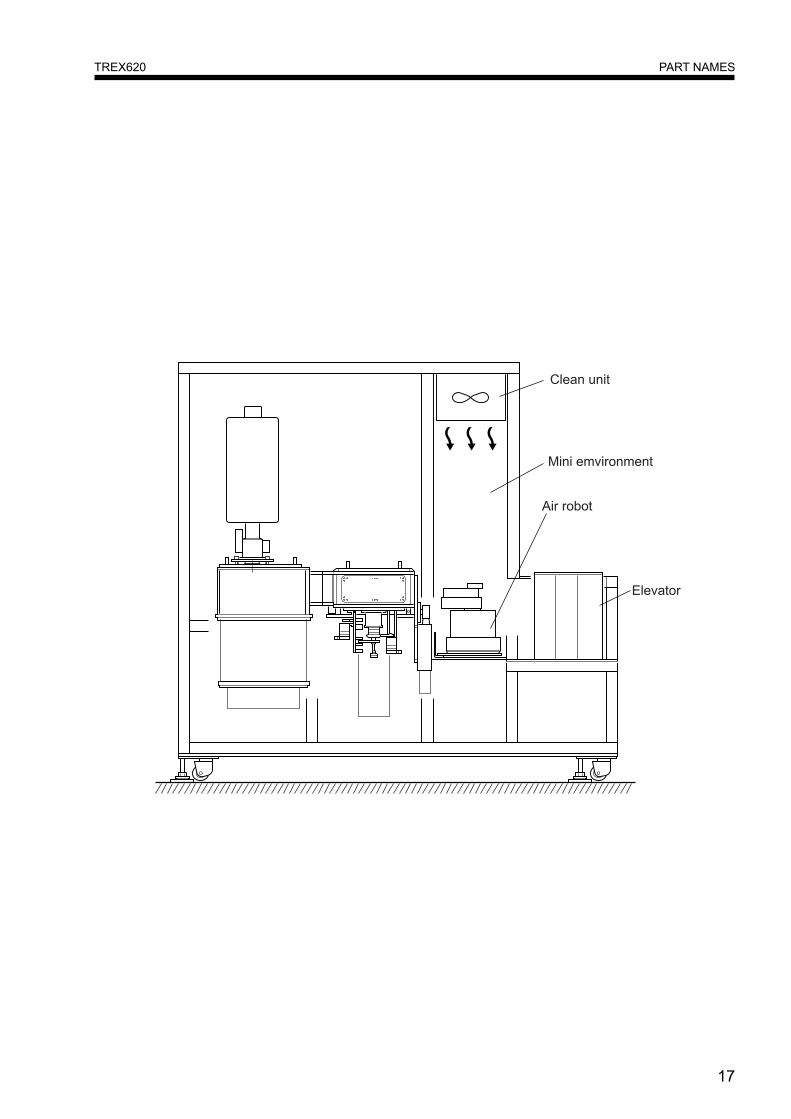
Unit Interior
17
PART NAMESTREX620
18
PART NAMESTREX620
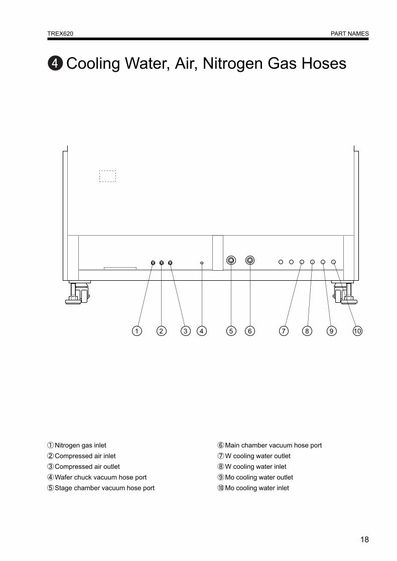
Cooling Water, Air, Nitrogen Gas Hoses
①Nitrogen gas inlet②Compressed air inlet③Compressed air outlet④Wafer chuck vacuum hose port⑤Stage chamber vacuum hose port
⑥Main chamber vacuum hose port⑦W cooling water outlet⑧W cooling water inlet⑨Mo cooling water outlet⑩Mo cooling water inlet
19
HOSESTREX620
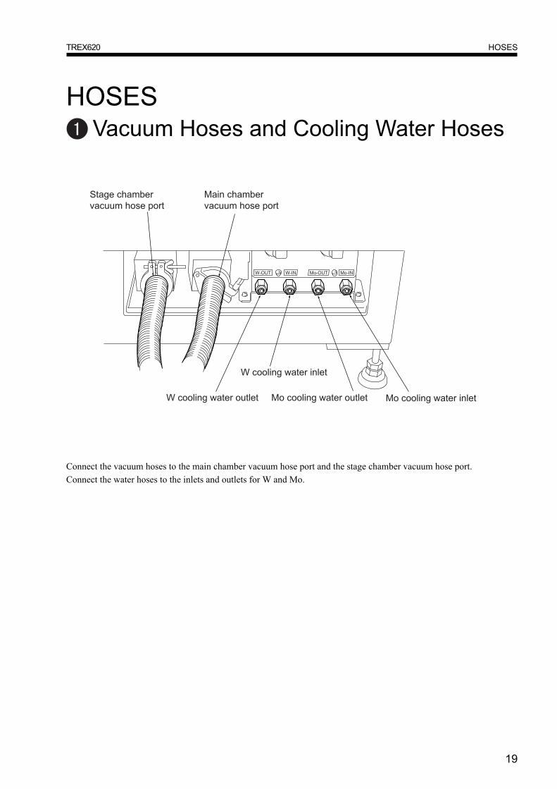
HOSESVacuum Hoses and Cooling Water Hoses
Connect the vacuum hoses to the main chamber vacuum hose port and the stage chamber vacuum hose port.Connect the water hoses to the inlets and outlets for W and Mo.
20
HOSESTREX620
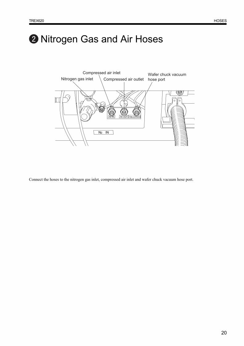
Nitrogen Gas and Air Hoses
Connect the hoses to the nitrogen gas inlet, compressed air inlet and wafer chuck vacuum hose port.
21
UNIT STARTING AND STOPPINGTREX620
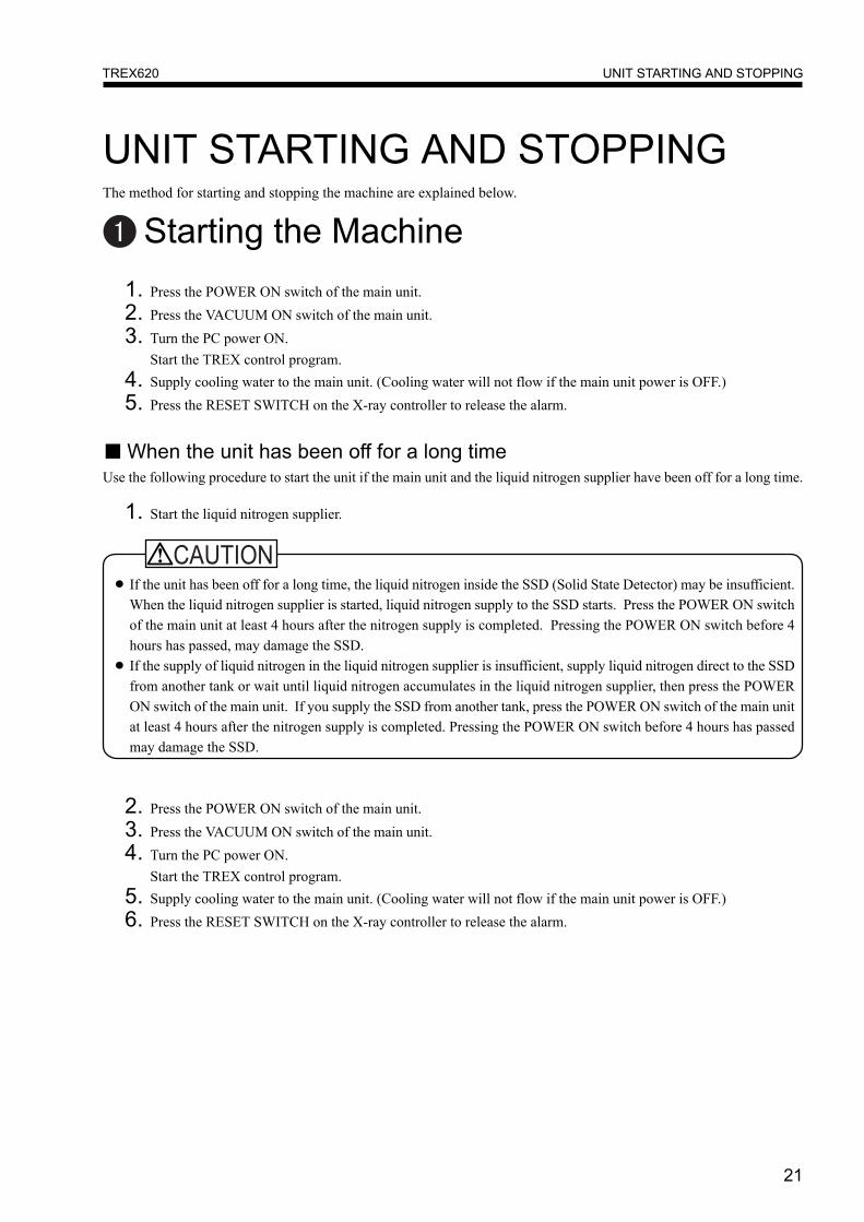
UNIT STARTING AND STOPPINGThe method for starting and stopping the machine are explained below.
Starting the Machine
● If the unit has been off for a long time, the liquid nitrogen inside the SSD (Solid State Detector) may be insufficient.When the liquid nitrogen supplier is started, liquid nitrogen supply to the SSD starts. Press the POWER ON switchof the main unit at least 4 hours after the nitrogen supply is completed. Pressing the POWER ON switch before 4hours has passed, may damage the SSD.
● If the supply of liquid nitrogen in the liquid nitrogen supplier is insufficient, supply liquid nitrogen direct to the SSDfrom another tank or wait until liquid nitrogen accumulates in the liquid nitrogen supplier, then press the POWERON switch of the main unit. If you supply the SSD from another tank, press the POWER ON switch of the main unitat least 4 hours after the nitrogen supply is completed. Pressing the POWER ON switch before 4 hours has passedmay damage the SSD.
1. Press the POWER ON switch of the main unit.2. Press the VACUUM ON switch of the main unit.3. Turn the PC power ON.
Start the TREX control program.4. Supply cooling water to the main unit. (Cooling water will not flow if the main unit power is OFF.)5. Press the RESET SWITCH on the X-ray controller to release the alarm.
■ When the unit has been off for a long timeUse the following procedure to start the unit if the main unit and the liquid nitrogen supplier have been off for a long time.
1. Start the liquid nitrogen supplier.
2. Press the POWER ON switch of the main unit.3. Press the VACUUM ON switch of the main unit.4. Turn the PC power ON.
Start the TREX control program.5. Supply cooling water to the main unit. (Cooling water will not flow if the main unit power is OFF.)6. Press the RESET SWITCH on the X-ray controller to release the alarm.
22
UNIT STARTING AND STOPPINGTREX620
Stopping the Machine
● The X-ray tube is hot immediately after the X-rays stop, so supply cooling water to the main unit for about 30minutes after the X-rays stop.
1. Stop cooling water supply to the main unit.2. Stop the TREX control program, then turn the PC power OFF.3. Press the VACUUM OFF switch of the main unit, then wait 10 minites before performing the next step.4. Press the POWER OFF switch of the main unit.
Emergency Procedure1. Press the EMERGENCY OFF button on the main unit.2. Stop cooling water supply to the main unit.3. Stop cooling water supply to the liquid nitrogen supplier.4. Stop the nitrogen gas compressed air.
Recovery Procedure After Emergency OFF1. Turn the emergency OFF switch on the main unit in the direction of the arrow to release the switch.2. Press the ON switch of the distribution board.3. Turn ON the power of the liquid nitrogen supplier.4. Press the POWER ON switch of the main unit.5. Press the VACUUM ON switch of the main unit.6. Turn the PC power ON. Start the TREX control program.7. Supply cooling water to the main unit. (Cooling water will not flow if the main unit power is OFF.)8. Press the RESET SWITCH on the X-ray controller to release the alarm.
23
TREX CONTROL PROGRAM OPERATIONTREX620
TREX CONTROL PROGRAM OPERATIONThe operation method of the TREX control program is explained below.
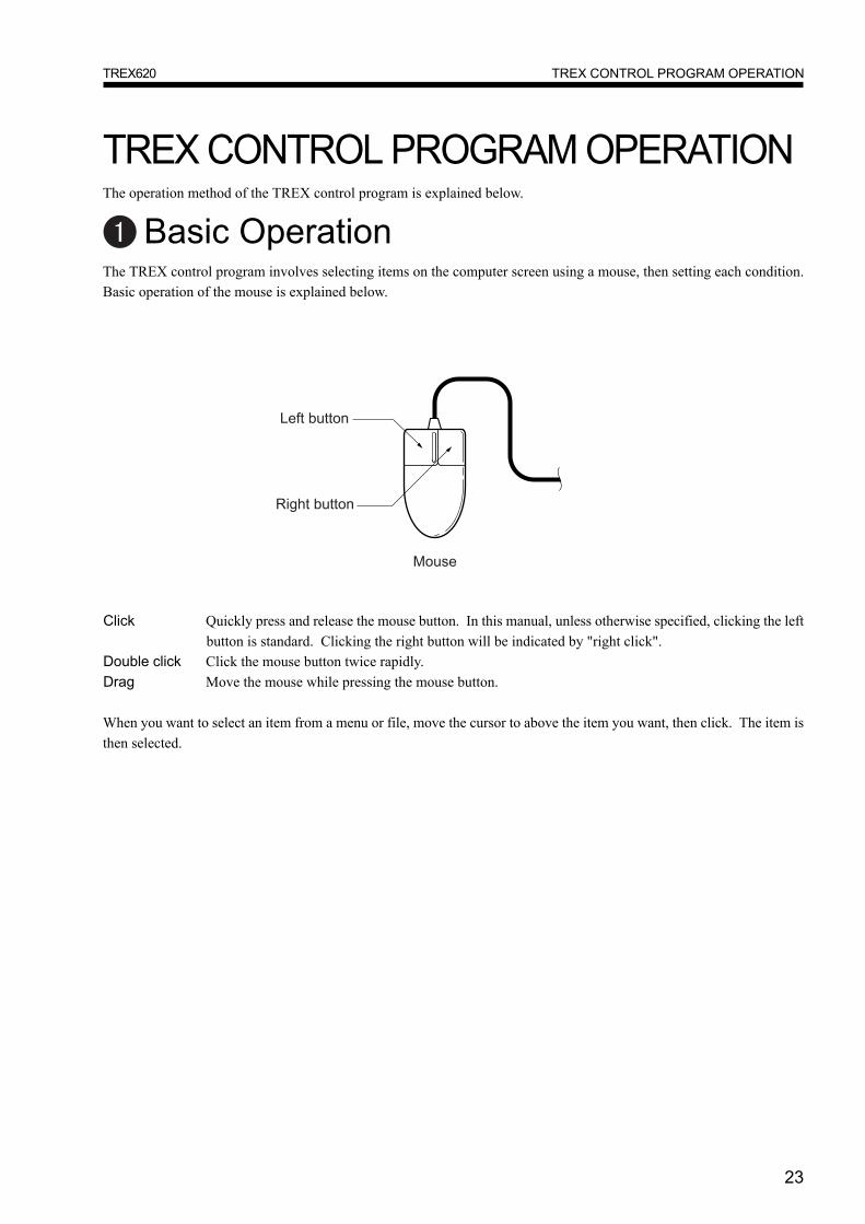
Basic OperationThe TREX control program involves selecting items on the computer screen using a mouse, then setting each condition.Basic operation of the mouse is explained below.
Click Quickly press and release the mouse button. In this manual, unless otherwise specified, clicking the leftbutton is standard. Clicking the right button will be indicated by "right click".
Double click Click the mouse button twice rapidly.Drag Move the mouse while pressing the mouse button.
When you want to select an item from a menu or file, move the cursor to above the item you want, then click. The item isthen selected.
24
TREX CONTROL PROGRAM OPERATIONTREX620
Start and End of Control ProgramThe start and end method of the TREX control program is explained below.
■ Control Program StartPress the POWER ON switch of the main unit to start the main unit.Turn the PC power ON and after Windows is invoked, start the TREX control program using the following procedure.
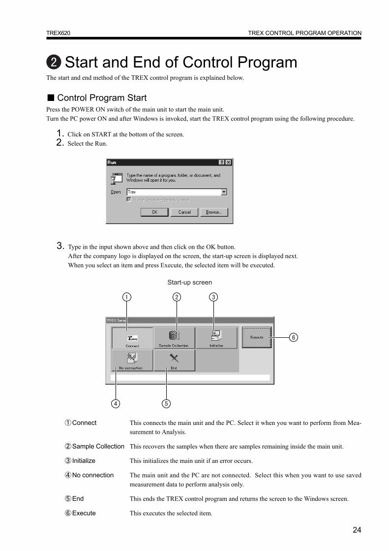
1. Click on START at the bottom of the screen.2. Select the Run.
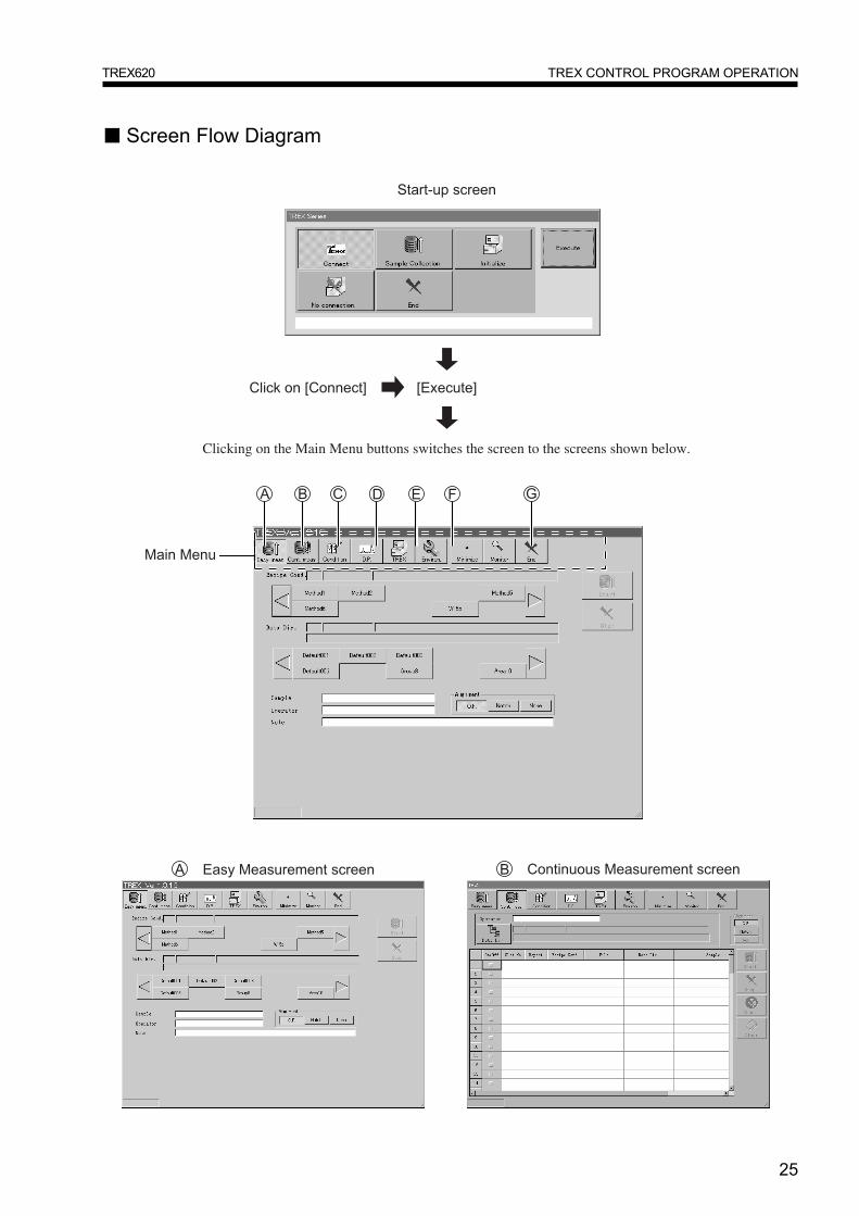
①Connect This connects the main unit and the PC. Select it when you want to perform from Mea-surement to Analysis.
②Sample Collection This recovers the samples when there are samples remaining inside the main unit.
③ Initialize This initializes the main unit if an error occurs.
④No connection The main unit and the PC are not connected. Select this when you want to use savedmeasurement data to perform analysis only.
⑤End This ends the TREX control program and returns the screen to the Windows screen.
⑥Execute This executes the selected item.
3. Type in the input shown above and then click on the OK button.After the company logo is displayed on the screen, the start-up screen is displayed next.When you select an item and press Execute, the selected item will be executed.
25
TREX CONTROL PROGRAM OPERATIONTREX620
■ Screen Flow Diagram
Clicking on the Main Menu buttons switches the screen to the screens shown below.

26
TREX CONTROL PROGRAM OPERATIONTREX620

27
TREX CONTROL PROGRAM OPERATIONTREX620
28
TREX CONTROL PROGRAM OPERATIONTREX620

29
TREX CONTROL PROGRAM OPERATIONTREX620
30
TREX CONTROL PROGRAM OPERATIONTREX620
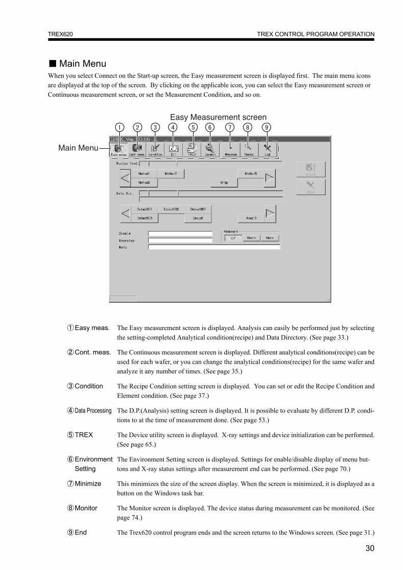
■ Main MenuWhen you select Connect on the Start-up screen, the Easy measurement screen is displayed first. The main menu iconsare displayed at the top of the screen. By clicking on the applicable icon, you can select the Easy measurement screen orContinuous measurement screen, or set the Measurement Condition, and so on.
①Easy meas. The Easy measurement screen is displayed. Analysis can easily be performed just by selectingthe setting-completed Analytical condition(recipe) and Data Directory. (See page 33.)
②Cont. meas. The Continuous measurement screen is displayed. Different analytical conditions(recipe) can beused for each wafer, or you can change the analytical conditions(recipe) for the same wafer andanalyze it any number of times. (See page 35.)
③Condition The Recipe Condition setting screen is displayed. You can set or edit the Recipe Condition andElement condition. (See page 37.)
④Data Processing The D.P.(Analysis) setting screen is displayed. It is possible to evaluate by different D.P. condi-tions to at the time of measurement done. (See page 53.)
⑤TREX The Device utility screen is displayed. X-ray settings and device initialization can be performed.(See page 65.)
⑥Environment The Environment Setting screen is displayed. Settings for enable/disable display of menu but-Setting tons and X-ray status settings after measurement end can be performed. (See page 70.)
⑦Minimize This minimizes the size of the screen display. When the screen is minimized, it is displayed as abutton on the Windows task bar.
⑧Monitor The Monitor screen is displayed. The device status during measurement can be monitored. (Seepage 74.)
⑨End The Trex620 control program ends and the screen returns to the Windows screen. (See page 31.)
31
TREX CONTROL PROGRAM OPERATIONTREX620
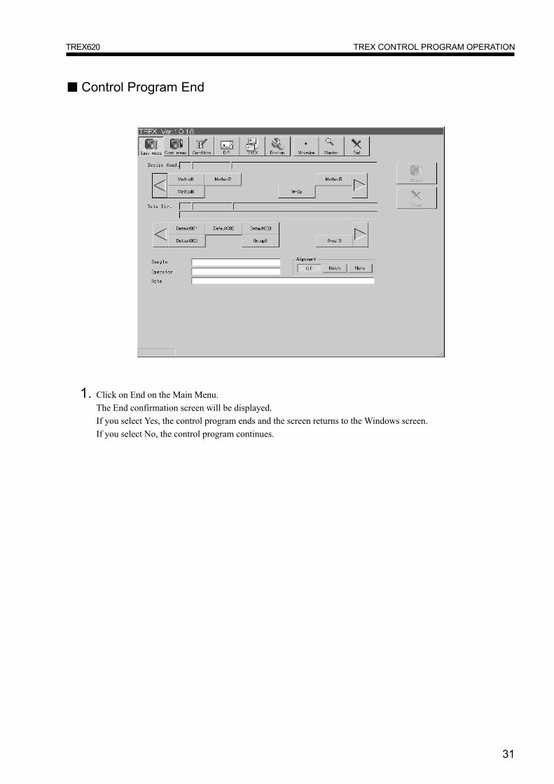
1. Click on End on the Main Menu.The End confirmation screen will be displayed.If you select Yes, the control program ends and the screen returns to the Windows screen.If you select No, the control program continues.
■ Control Program End
32
TREX CONTROL PROGRAM OPERATIONTREX620
■ PC EndBefore you turn OFF the PC power, always check that measurement is completed.
1. Click on Start displayed at the lower left of the screen.Windows Start menu is displayed.
2. Select End Windows from the Start Menu.The confirmation screen for turning OFF the PC power will be displayed.
3. Select "Prepare computer for power turn off", then click Yes.Soon the screen will display the message "Computer ready for power OFF", and the computer will automaticallyturn OFF.
● If you turn off PC power while measurement is performing machine will stop with the sample still inside the machine.If this occurs, restart the control program, then recover the sample using Sample Collection on the start-up screen orthe TREX screen.
33
MEASUREMENTTREX620
MEASUREMENTEasy Measurement
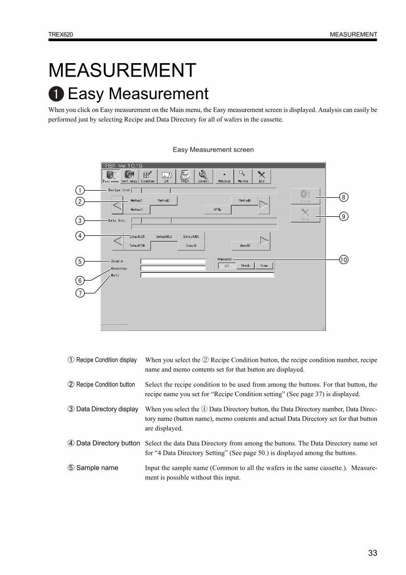
When you click on Easy measurement on the Main menu, the Easy measurement screen is displayed. Analysis can easily beperformed just by selecting Recipe and Data Directory for all of wafers in the cassette.
① Recipe Condition display When you select the ② Recipe Condition button, the recipe condition number, recipename and memo contents set for that button are displayed.
② Recipe Condition button Select the recipe condition to be used from among the buttons. For that button, therecipe name you set for “Recipe Condition setting” (See page 37) is displayed.
③ Data Directory display When you select the ④ Data Directory button, the Data Directory number, Data Direc-tory name (button name), memo contents and actual Data Directory set for that buttonare displayed.
④ Data Directory button Select the data Data Directory from among the buttons. The Data Directory name setfor “4 Data Directory Setting” (See page 50.) is displayed among the buttons.
⑤ Sample name Input the sample name (Common to all the wafers in the same cassette.). Measure-ment is possible without this input.
34
MEASUREMENTTREX620
●Recipe Condition button, Data Directory button● For each button, the applicable Recipe name and Data Directory name set for “Recipe Condition setting” (See page
37) and “4 Data Directory setting” (See page 50) are displayed. A maximum of 10 buttons can be displayed on thescreen. To display buttons not displayed on the screen, click on the ▲� ▼ buttons at the left and right of the screen.The button display changes over in units of 10 buttons each time.Buttons for which nothing is set on “Recipe Condition setting” (See page 37) and “4 Data Directory setting” (Seepage 50) are not displayed.
●Saving Measurement Data● For Easy measurement, the file name is automatically set for the measurement data with the date and number. Changes
are not possible.
⑥Operator Input the name of the operator executing the measurement. Measurement is possible withoutthis input.
⑦Note Enter a Note about the measurement conditions. You can enter up to 40 one-byte characters.
⑧Start Measurement starts.
⑨Stop Measurement stops before completion All samples inside the machine are collected. If youclick on Start again, measurement starts again from the start.
⑩Alignment This sets the wafer shape. This setting is common for all the wafers inside the cassette. Thisbutton is only displayed when "Decide Before Start Meas." is selected for Setting of WaferAlignment on the Setting screen (See page 70).
35
MEASUREMENTTREX620
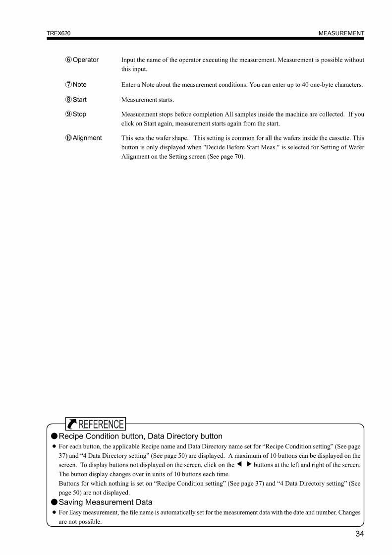
Continuous MeasurementWhen you click on Continuous measurement on the Main Menu, the Continuous measurement screen is displayed. Differ-ent analytical conditions can be used for each wafer, or you can change the analytical conditions for the same wafer andanalyze it any number of times.
①Operator Input the name of the operator executing the measurement. Measurement is possiblewithout this input.
②Data Directory When your press the button, the Data Directory names set for “4 Data Directory Setting”selection button (See page 50) are listed. Select the Data Directory for measurement data from the list. In
the text box next to the button, the Data Directory number and Data Directory name (but-ton name), memo contents and actual Data Directory set for that Data Directory are dis-played.
③On/Off Used for checking the items you want to measure. Lines not checked are not measured.
④Slot No Input the slot number containing the sample to be measured.
⑤Repeat When you want to repeat measurement, input the number of measurement times required.
⑥Recipe Cond. Select the recipe condition used for analysis. When you click on Recipe Cond., the recipeconditions set for “Recipe Condition Setting” (See page 37) are listed. Select the RecipeCondition from the list.
⑦File Enter the file name for the measurement data to be saved.
⑧Data Directory Input the Save space when you want to input data at a place other than the place selectedat ② Data Directory selection button.
36
MEASUREMENTTREX620
⑨Sample name Input the sample name. Measurement is possible without this input.
⑩Alignment This sets the wafer shape. This setting is common for all the wafers inside the cassette. Thisbutton is only displayed when "Decide Before Start Meas." is selected for Setting of WaferAlignment on the Setting screen (See page 70).
⑪Start The PC perform logical check for all item set, and if all are valid or aceptable, startsmeasurement.
⑫Stop Measurement stops before completion All samples inside the machine are collected. If youclick on Start, measurement starts again from the start.
⑬Check Check whether the set contents are valid or not. If there is an error in the set contents, amessage is displayed, so recheck the set contents if this occurs.
⑭Clear Deletes ALL the set contents. It is not possible to delete only selected lines.
● You can enter a Note about the measurement conditions in the Remarks box at the left side. You can enter up to 40one-byte characters.

37
RECIPE CONDITION SETTINGTREX620
RECIPE CONDITION SETTINGWhen you click on Condition on the Main Menu, the Recipe Condition screen is displayed. On the Recipe Conditionscreen, you can create new recipe conditions or edit existing ones.
①Recipe Condition The Recipe Condition screen is displayed. You can input a name for the recipe conditionand save it, or set the measurement condition and element condition. (See page 38.)
②Element Condition The Element Condition screen is displayed. Set the elements for analysis as the elementcondition. (See page 46.)
③Quant. Condition The quantification condition screen is displayed. Make calibration coefficient. (See page48.)
④Data Directory The Data Directory screen is displayed. Set the Data Directory for the measurement data.(See page 50.)
⑤Option The Option setting screen is displayed. Set the Option functions. (See page 52.)
⑥Returns The screen returns to the Main Menu.

38
RECIPE CONDITION SETTINGTREX620
Recipe Condition SettingWhen you click on Recipe Condition on the Recipe Condition setting screen, the Recipe Condition screen is displayed.You can input a name for the recipe condition and save it, or set the measurement condition and element condition.
①Recipe setting tab Clicking on one of the heading tabs will display the applicable screen for setting eachcondition.
②Recipe condition button Select the button for setting each recipe condition. If the recipe is existing, the recipename is displayed.
③Create When you select the ② Recipe Condition button for new recipe condition and click theCreate button, you can then create a new recipe condition.
④Edit When you select the ② Recipe Condition button for existing recipe condition andclick the Edit button, you can then edit the Recipe condition.
⑤Delete This deletes the conditions set for the selected ② Recipe Condition button.
⑥Copy This copies the button set contents displayed at ⑨ Recipe Condition (source) to thebutton displayed at ⑩ Free area (destination).
⑦Move This moves the button set contents displayed at ⑨ Recipe Condition (source) to thebutton displayed at ⑩ Free area (destination). The button contents set at ⑨ RecipeCondition (source) are deleted.
39
RECIPE CONDITION SETTINGTREX620
⑧Save This saves the edited contents. When the Save button is clicked, the confirmationdialog box is displayed.
⑨Recipe Condition (source) When the ② Recipe condition button for recipe condition setting completion is se-lected when editing, copying or moving the recipe condition, the recipe number andrecipe name of that button are displayed.
⑩Free area (destination) When the ② Recipe condition button for a non-set recipe condition is selected whencreating, copying or moving the recipe condition, the recipe number of that button isdisplayed.
●Recipe condition button● The Recipe condition button can register a maximum of 100 items. The screen displays 10 Recipe condition buttons.
To display buttons not displayed on the screen, click on the ▲� ▼ buttons at the left and right of the screen. Thebutton display changes over in units of 10 buttons each time.
40
RECIPE CONDITION SETTINGTREX620
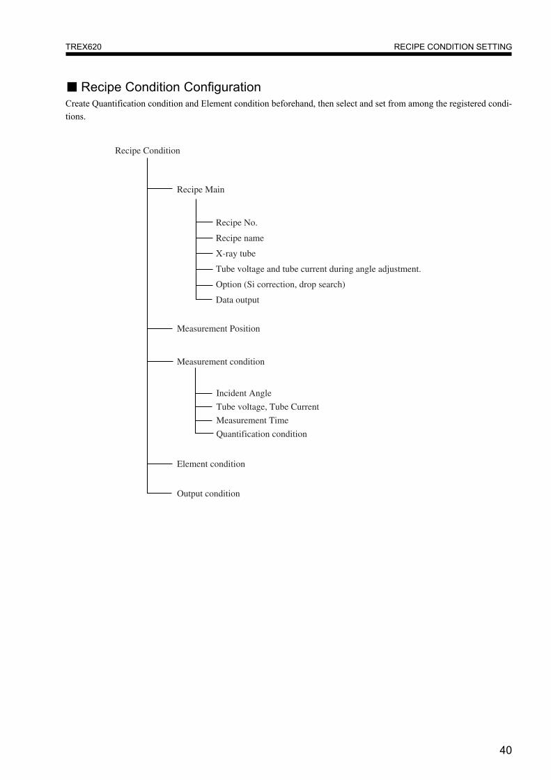
■ Recipe Condition ConfigurationCreate Quantification condition and Element condition beforehand, then select and set from among the registered condi-tions.
Recipe Condition
Recipe Main
Recipe No.
Measurement Position
Element condition
Output condition
Measurement condition
Incident Angle
Tube voltage, Tube Current
Measurement Time
Quantification condition
Recipe name
X-ray tube
Tube voltage and tube current during angle adjustment.
Option (Si correction, drop search)
Data output
41
RECIPE CONDITION SETTINGTREX620
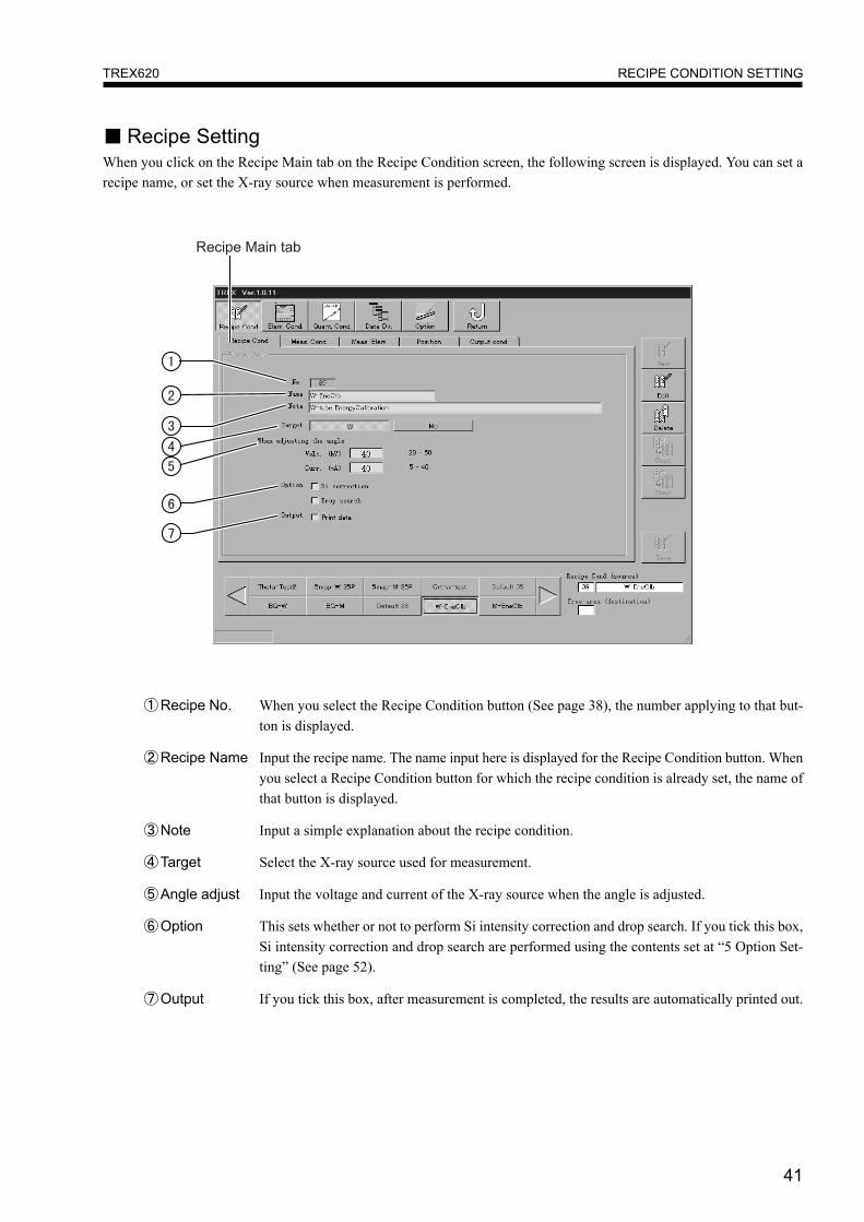
①Recipe No. When you select the Recipe Condition button (See page 38), the number applying to that but-ton is displayed.
②Recipe Name Input the recipe name. The name input here is displayed for the Recipe Condition button. Whenyou select a Recipe Condition button for which the recipe condition is already set, the name ofthat button is displayed.
③Note Input a simple explanation about the recipe condition.
④Target Select the X-ray source used for measurement.
⑤Angle adjust Input the voltage and current of the X-ray source when the angle is adjusted.
⑥Option This sets whether or not to perform Si intensity correction and drop search. If you tick this box,Si intensity correction and drop search are performed using the contents set at “5 Option Set-ting” (See page 52).
⑦Output If you tick this box, after measurement is completed, the results are automatically printed out.
■ Recipe SettingWhen you click on the Recipe Main tab on the Recipe Condition screen, the following screen is displayed. You can set arecipe name, or set the X-ray source when measurement is performed.
42
RECIPE CONDITION SETTINGTREX620
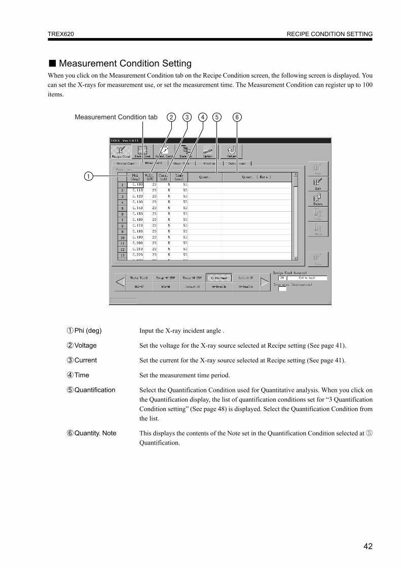
①Phi (deg) Input the X-ray incident angle .
②Voltage Set the voltage for the X-ray source selected at Recipe setting (See page 41).
③Current Set the current for the X-ray source selected at Recipe setting (See page 41).
④Time Set the measurement time period.
⑤Quantification Select the Quantification Condition used for Quantitative analysis. When you click onthe Quantification display, the list of quantification conditions set for “3 QuantificationCondition setting” (See page 48) is displayed. Select the Quantification Condition fromthe list.
⑥Quantity. Note This displays the contents of the Note set in the Quantification Condition selected at ⑤Quantification.
■ Measurement Condition SettingWhen you click on the Measurement Condition tab on the Recipe Condition screen, the following screen is displayed. Youcan set the X-rays for measurement use, or set the measurement time. The Measurement Condition can register up to 100items.

43
RECIPE CONDITION SETTINGTREX620
■ Element Condition SelectionWhen you click on the Element Condition selection tab on the Recipe Condition screen, the following screen is displayed.Select the Element Condition for analysis.
①Element Condition selection button Select the Element Condition used for analysis. Clicking on the buttondisplays the list of Element Conditions set at “2 Element Condition Set-ting” (See page 46). Select the Element Condition from the list.
②Element Condition Display The element symbol displayed is switched in accordance with the se-lected Element Condition setting.
● Perform editing of the Element Condition at “2 Element Condition Setting” (See page 46).

44
RECIPE CONDITION SETTINGTREX620
①Measurement position display This indicates the set measurement position. The measurement position is indi-cated by the black spot. By clicking on the graph with the mouse, you canspecify the closest grid intersection as the measurement position.
②Wafer Size Specify the size of the wafers to be measured.
③Wafer Size display Display the specified wafer size is displayed.
④Measurement position Set the measurement position.setting XY Mode : With the wafer center as 0, input the measurement position using
X, Y coordinates.RT Mode : Set the measurement position using R (radius) and T (angle).
⑤Grid setting Clicking here displays the screen for setting the grid display method.
⑥Enlarge/reduce display Each click on the icon either enlarges or reduces the size of the measurementposition display (graph display).
■ Measurement Position SettingWhen you click on the Meas. Pos. setting tab on the Recipe Condition screen, the following screen is displayed. Set thewafer size and measurement position.
●Measurement position specification● When specifying the position using coordinates, input the units in millimeters. Input figures up to the second deci-
mal place.● Measurement positions can be specified up to 100 locations.● If some wafers are not displayed on the measurement position display (graph display), use ▼/▲ to drag the scroll
bars up or down, or left to right. The screen display will move.
45
RECIPE CONDITION SETTINGTREX620
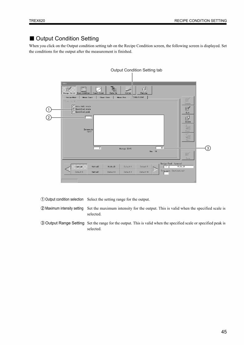
■ Output Condition SettingWhen you click on the Output condition setting tab on the Recipe Condition screen, the following screen is displayed. Setthe conditions for the output after the measurement is finished.
①Output condition selection Select the setting range for the output.
②Maximum intensity setting Set the maximum intensity for the output. This is valid when the specified scale isselected.
③Output Range Setting Set the range for the output. This is valid when the specified scale or specified peak isselected.
46
RECIPE CONDITION SETTINGTREX620
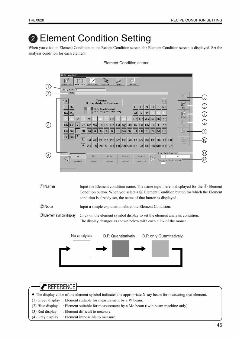
Element Condition SettingWhen you click on Element Condition on the Recipe Condition screen, the Element Condition screen is displayed. Set theanalysis condition for each element.
①Name Input the Element condition name. The name input here is displayed for the ④ ElementCondition button. When you select a ④ Element Condition button for which the Elementcondition is already set, the name of that button is displayed.
②Note Input a simple explanation about the Element Condition.
③Element symbol display Click on the element symbol display to set the element analysis condition.The display changes as shown below with each click of the mouse.
● The display color of the element symbol indicates the appropriate X-ray beam for measuring that element.(1) Green display : Element suitable for measurement by a W beam.(2) Blue display : Element suitable for measurement by a Mo beam (twin beam machine only).(3) Red display : Element difficult to measure.(4) Gray display : Element impossible to measure.
47
RECIPE CONDITION SETTINGTREX620
●Element condition button● The Element condition button can register a maximum of 100 items. The screen displays 10 Element condition
buttons. To display buttons not displayed on the screen, click on the ▲� ▼ buttons at the left and right of the screen.The button display changes over in units of 10 buttons each time.
④Element Condition Button Select the button to set the element condition. For already set buttons, the elementcondition name is displayed.
⑤New When you select the non-set ④ Element Condition button and click the Create button,you can then create a new Element condition.
⑥Edit When you select the ④ Element Condition button for already set Element Conditionand click the Edit button, you can edit the Element Condition.
⑦Delete This deletes the conditions set for the selected ④ Element Condition button.
⑧Save This saves the edited contents. When the Save button is clicked, the confirmation dia-log box is displayed.
⑨Copy This copies the button set contents displayed at ⑪ Element Condition (source) to thebutton displayed at ⑫ Free area (destination).
⑩Move This moves the button set contents displayed at ⑪ Element Condition (source) to thebutton displayed at ⑫ Free area (destination). The button contents set at ⑪ ElementCondition (source) are deleted.
⑪Element Condition (source) When you select the ④ Element condition button for an already set Element conditionwhen editing, copying or moving the Element condition, the condition number andcondition name of that button are displayed.
⑫Free area (destination) When the ④ Element condition button for a non-set Element condition is selectedwhen creating, copying or moving the recipe condition, the condition number of thatbutton is displayed.
48
RECIPE CONDITION SETTINGTREX620
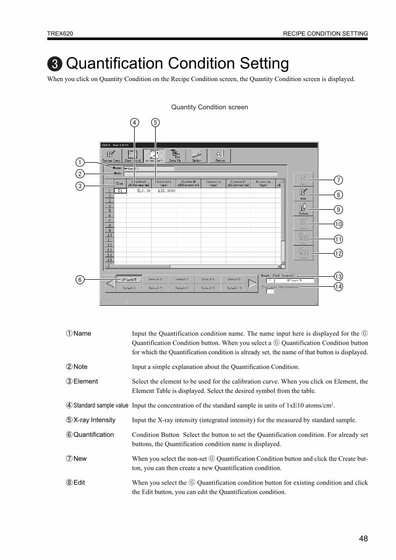
Quantification Condition SettingWhen you click on Quantity Condition on the Recipe Condition screen, the Quantity Condition screen is displayed.
①Name Input the Quantification condition name. The name input here is displayed for the ⑥Quantification Condition button. When you select a ⑥ Quantification Condition buttonfor which the Quantification condition is already set, the name of that button is displayed.
②Note Input a simple explanation about the Quantification Condition.
③Element Select the element to be used for the calibration curve. When you click on Element, theElement Table is displayed. Select the desired symbol from the table.
④Standard sample value Input the concentration of the standard sample in units of 1xE10 atoms/cm2.
⑤X-ray Intensity Input the X-ray intensity (integrated intensity) for the measured by standard sample.
⑥Quantification Condition Button Select the button to set the Quantification condition. For already setbuttons, the Quantification condition name is displayed.
⑦New When you select the non-set ⑥ Quantification Condition button and click the Create but-ton, you can then create a new Quantification condition.
⑧Edit When you select the ⑥ Quantification condition button for existing condition and clickthe Edit button, you can edit the Quantification condition.

49
RECIPE CONDITION SETTINGTREX620
⑨Delete This deletes the conditions set for the selected ⑥ Quantification condition button.
⑩Save This saves the edited contents. When the Save button is clicked, the confirmationdialog box is displayed.
⑪Copy This copies the button set contents displayed at ⑬ Quantification Condition (source)to the button displayed at ⑭ Free area (destination).
⑫Move This moves the button set contents displayed at ⑬ Quantification Condition (source)to the button displayed at ⑭ Free area (destination). The button contents set at ⑬Quantification Condition (source) are deleted.
⑬Quantification When you select the ⑥ Quantification condition button for an already set QuantificationCondition (source) condition when editing, copying or moving the Quantification condition, the condi-
tion number and condition name of that button are displayed.
⑭Free area (destination) When you select the ⑥ Quantification condition button for a non-set Quantificationcondition when creating, copying or moving the recipe condition, the condition num-ber of that button is displayed.
●Quantification condition button● The Quantification condition button can register a maximum of 100 items. The screen displays 10 Quantity condi-
tion buttons. To display buttons not displayed on the screen, click on the ▲� ▼ buttons at the left and right of thescreen. The button display changes over in units of 10 buttons each time.
50
RECIPE CONDITION SETTINGTREX620
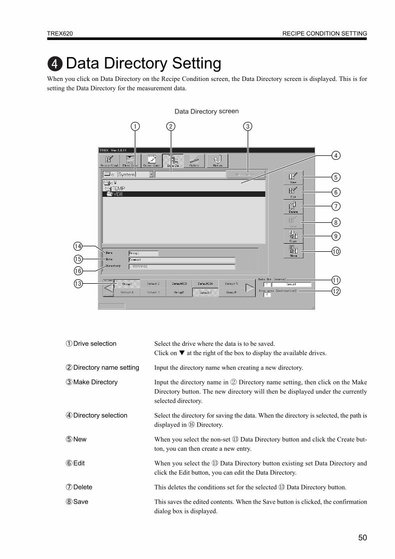
Data Directory SettingWhen you click on Data Directory on the Recipe Condition screen, the Data Directory screen is displayed. This is forsetting the Data Directory for the measurement data.
①Drive selection Select the drive where the data is to be saved.Click on ▼ at the right of the box to display the available drives.
②Directory name setting Input the directory name when creating a new directory.
③Make Directory Input the directory name in ② Directory name setting, then click on the MakeDirectory button. The new directory will then be displayed under the currentlyselected directory.
④Directory selection Select the directory for saving the data. When the directory is selected, the path isdisplayed in ⑯ Directory.
⑤New When you select the non-set ⑬ Data Directory button and click the Create but-ton, you can then create a new entry.
⑥Edit When you select the ⑬ Data Directory button existing set Data Directory andclick the Edit button, you can edit the Data Directory.
⑦Delete This deletes the conditions set for the selected ⑬ Data Directory button.
⑧Save This saves the edited contents. When the Save button is clicked, the confirmationdialog box is displayed.
51
RECIPE CONDITION SETTINGTREX620
⑨Copy This copies the button set contents displayed at ⑪ Data Dir. (source) to the buttondisplayed at ⑫ Free area (destination).
⑩Move This moves the button set contents displayed at ⑪ Data Dir. (source) to the buttondisplayed at ⑫ Free area (destination). The button contents set at ⑪ Data Dir. (source)are deleted.
⑪Data Dir. (source) When you select the ⑬ Data Directory button for an already set Data Directory whenediting, copying or moving the Data Directory, the condition number and Data Direc-tory name of that button are displayed.
⑫Free area (destination) When you select the ⑬ Data Directory button for a non-set Data Directory whencreating, copying or moving the Data Directory, the condition number of that button isdisplayed.
⑬Data Directory button Select the button for setting the Data Directory. The Data Directory name is displayedfor buttons already set.
⑭Name Input the Data Directory name. The name input here is displayed at the ⑬ Data Direc-tory button. When you select the ⑬ Data Directory button for a Data Directory alreadyset, the button name is displayed.
⑮Note Input a simple explanation about the Data Directory.
⑯Directory The directory name where the data is actually saved is displayed.
●Data Directory button● The Data Directory condition button can register a maximum of 100 items. The screen displays 10 Quantity condi-
tion buttons. To display buttons not displayed on the screen, click on the ▲� ▼ buttons at the left and right of thescreen. The button display changes over in units of 10 buttons each time.
52
RECIPE CONDITION SETTINGTREX620
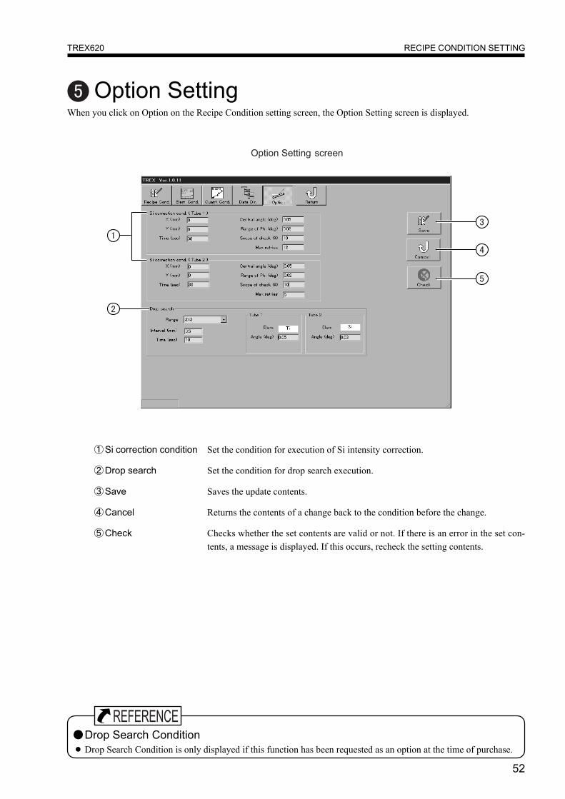
Option SettingWhen you click on Option on the Recipe Condition setting screen, the Option Setting screen is displayed.
①Si correction condition Set the condition for execution of Si intensity correction.
②Drop search Set the condition for drop search execution.
③Save Saves the update contents.
④Cancel Returns the contents of a change back to the condition before the change.
⑤Check Checks whether the set contents are valid or not. If there is an error in the set con-tents, a message is displayed. If this occurs, recheck the setting contents.
●Drop Search Condition● Drop Search Condition is only displayed if this function has been requested as an option at the time of purchase.

53
DATA PROCESSING (ANALYSIS)TREX620
DATA PROCESSING (ANALYSIS)When you click on Data Processing the Main Menu, the D.P. screen is displayed. You can set D.P. conditions for the resultsmeasured by Easy Measurement or Continuous Measurement, then perform data processing by different D.P. condition atthe time of measurement.
①1 point D.P. Selects one data item from the saved measurement data and recalculates it. (See page 54)
②Continuous D.P. Selects multiple data from the saved measurement data and recalculates it continuously.(See page 59)
③Mapping Displays the measurement results. (See page 62)
④Return Returns to the Main Menu.
54
DATA PROCESSING (ANALYSIS)TREX620
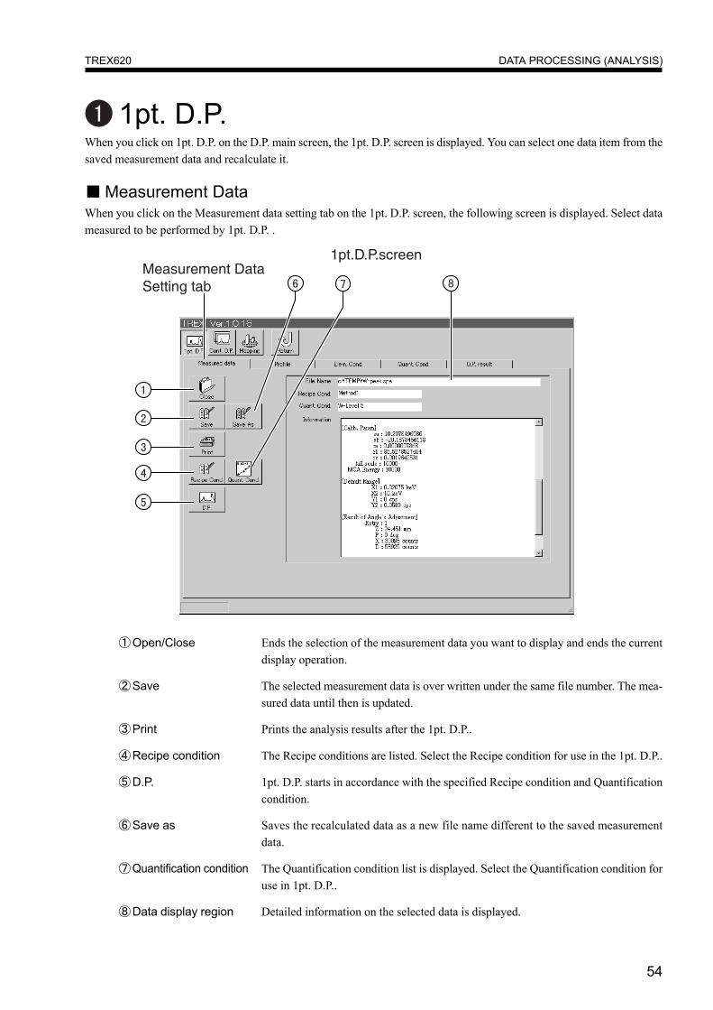
①Open/Close Ends the selection of the measurement data you want to display and ends the currentdisplay operation.
②Save The selected measurement data is over written under the same file number. The mea-sured data until then is updated.
③Print Prints the analysis results after the 1pt. D.P..
④Recipe condition The Recipe conditions are listed. Select the Recipe condition for use in the 1pt. D.P..
⑤D.P. 1pt. D.P. starts in accordance with the specified Recipe condition and Quantificationcondition.
⑥Save as Saves the recalculated data as a new file name different to the saved measurementdata.
⑦Quantification condition The Quantification condition list is displayed. Select the Quantification condition foruse in 1pt. D.P..
⑧Data display region Detailed information on the selected data is displayed.
1pt. D.P.When you click on 1pt. D.P. on the D.P. main screen, the 1pt. D.P. screen is displayed. You can select one data item from thesaved measurement data and recalculate it.
■ Measurement DataWhen you click on the Measurement data setting tab on the 1pt. D.P. screen, the following screen is displayed. Select datameasured to be performed by 1pt. D.P. .

55
DATA PROCESSING (ANALYSIS)TREX620
■ ProfileWhen you click on the Profile tab on the 1pt. D.P. screen, the screen below is displayed. The measurement data selected onthe previous page is displayed.
①Grid This sets whether or not the grid is displayed. It alternates between display/not displayeach time you click on it.
②Log This switches the intensity axis between the linear scale and log scale.
③Range This is for setting the display range of the data display area. Clicking on it will display thescreen for setting the display range so that you can set the X-ray intensity range and theenergy range.
④Default Data display occurs in accordance with the settings in Output Condition Setting on 1 RecipeCondition Setting (See page 45).
⑤Auto The display range is set automatically.
⑥Raw data This sets whether X-ray intensity is displayed as it is or whether smoothing is performed.The display method changes each time the button is clicked.
⑦Element ID Clicking on this displays the analysis element at the peak on the analysis waveform of thedata display area.
⑧Marker Select the type of X-ray indicated by the Basic Element ID or cursor ID. (The initial settingis Kα only.)
⑨Cursor ID When you move the cursor to the desired location on the displayed data, the element de-tected at that energy position is displayed near the cursor.
⑩Data display area The measurement data selected on the previous page is displayed.
56
DATA PROCESSING (ANALYSIS)TREX620
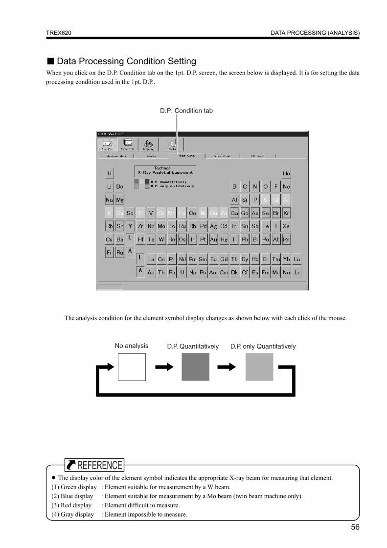
■ Data Processing Condition SettingWhen you click on the D.P. Condition tab on the 1pt. D.P. screen, the screen below is displayed. It is for setting the dataprocessing condition used in the 1pt. D.P..
The analysis condition for the element symbol display changes as shown below with each click of the mouse.
● The display color of the element symbol indicates the appropriate X-ray beam for measuring that element.(1) Green display : Element suitable for measurement by a W beam.(2) Blue display : Element suitable for measurement by a Mo beam (twin beam machine only).(3) Red display : Element difficult to measure.(4) Gray display : Element impossible to measure.
57
DATA PROCESSING (ANALYSIS)TREX620
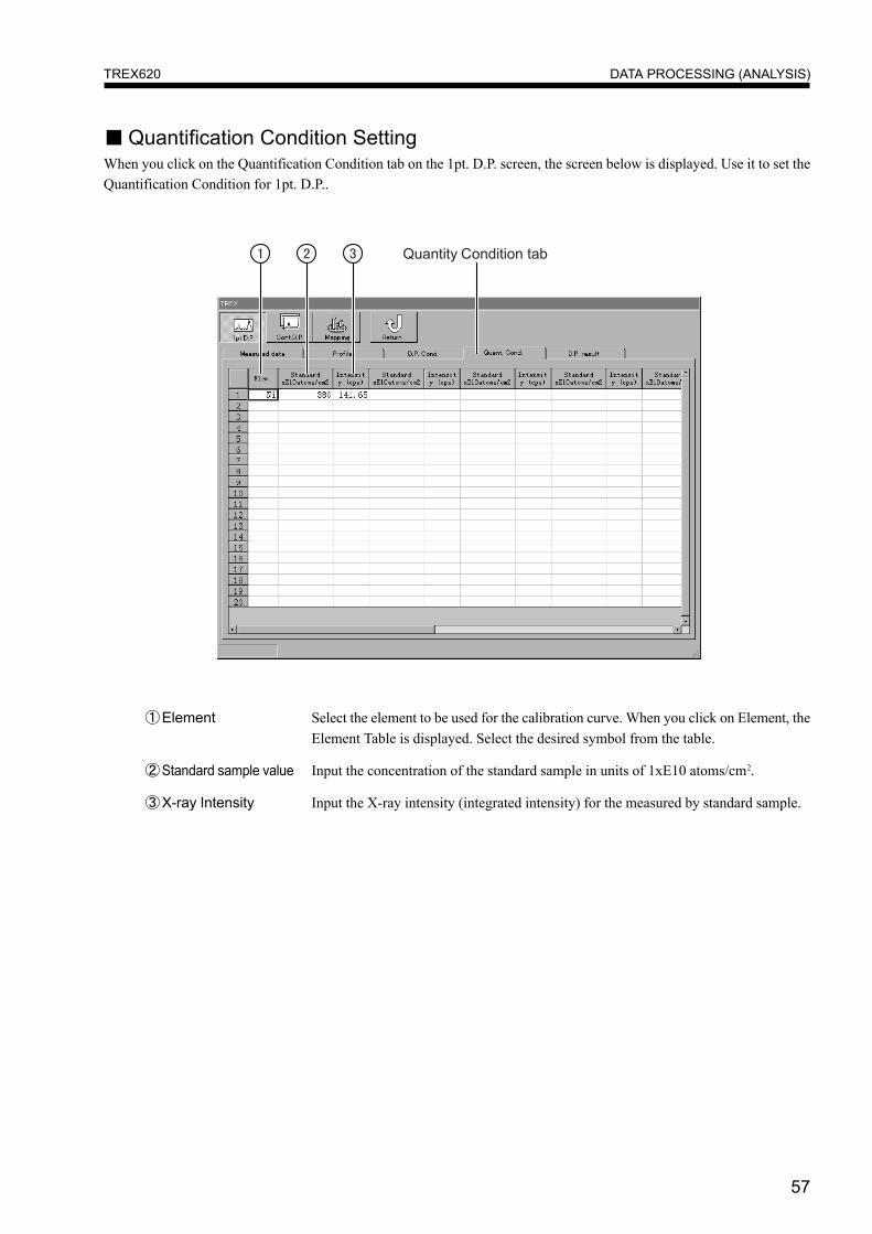
■ Quantification Condition SettingWhen you click on the Quantification Condition tab on the 1pt. D.P. screen, the screen below is displayed. Use it to set theQuantification Condition for 1pt. D.P..
①Element Select the element to be used for the calibration curve. When you click on Element, theElement Table is displayed. Select the desired symbol from the table.
②Standard sample value Input the concentration of the standard sample in units of 1xE10 atoms/cm2.
③X-ray Intensity Input the X-ray intensity (integrated intensity) for the measured by standard sample.
58
DATA PROCESSING (ANALYSIS)TREX620
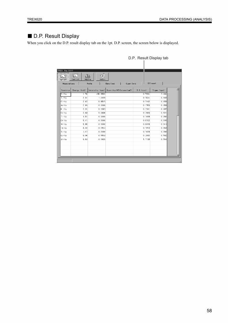
■ D.P. Result DisplayWhen you click on the D.P. result display tab on the 1pt. D.P. screen, the screen below is displayed.

59
DATA PROCESSING (ANALYSIS)TREX620
Continuous Data ProcessingWhen you click on Continuous D.P., the Continuous D.P. screen shown below is displayed. Multiple data can be selectedfrom the saved data and continuous D.P. is performed.
①Save as Dis file After analysis, check this this box when creating a Dis file. When you click onthe arrows at the right of the text box, a dialog box for file selection is dis-played for you to select the Dis file.
②Base file of Energy Check this box when you temporary change the energy calibration value.Calibration Coefficient When you click on the arrows at the right of the text box, a dialog box for file
selection is displayed for you to select a file.
③On/Off Put a check against each row if you want to check data processing. Lines thatdo not have a check against them are not processed.
④D.P. Put a check in the applicable box in this column when you want to performrecalculation. If there is no check, analysis is not performed.
⑤Print Check the Print box when you want to print the analysis result. If there is nocheck, printing is not performed.
⑥Save Check the Print box when you want to save the analysis result. If there is nocheck, the analysis result is not saved.
⑦File name Select the measured data you want for recalculation. When you click on Filename, the file names of the measured data are displayed in a list for you toselect the desired file from.

60
DATA PROCESSING (ANALYSIS)TREX620
⑧Recipe Condition Select the Recipe Condition for use in recalculation. When you click on Recipe Condition,the Recipe Condition list is displayed for you to select the analysis condition.
⑨Quantification Select the Quantification Condition for use in recalculation. When you click on Quantifi-Condition cation condition, the Quantification Condition list is displayed for your selection.
⑩Save file name Input the file name when you want to save using a different file name to the time of mea-surement. If the file name is not input, the data is saved using the name at ⑦ File name.
⑪Start Confirm whether the set contents are valid or not. If they are valid, start the analysis opera-tion. If there is an error in the set contents, a message is displayed. If this occurs, check theset contents again.
⑫Stop This stops Data Processing.
⑬Check This checks whether the set contents are valid or not. If there is an error in the set contents,a message is displayed. If this occurs, check the set contents again.
⑭Clear This erases all the set contents. It is not possible to delete only the desired lines.
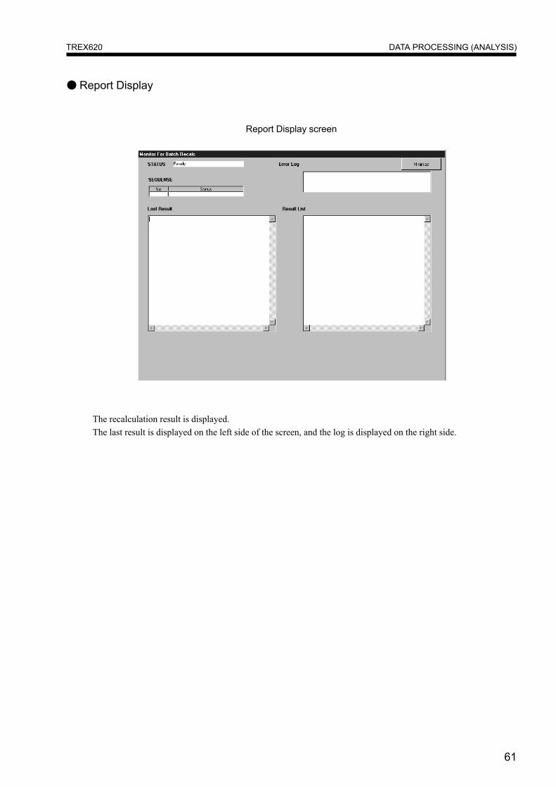
⑮Report The recalculation result is displayed on the screen simply. (See next page.)
61
DATA PROCESSING (ANALYSIS)TREX620
● Report Display
The recalculation result is displayed.The last result is displayed on the left side of the screen, and the log is displayed on the right side.
Report Display screen

62
DATA PROCESSING (ANALYSIS)TREX620
Mapping DisplayWhen you click on Mapping Display on the D.P. screen, the Mapping Display screen shown below is displayed. You canchoose between a 3-dimensional display or a 2-dimensional display showing a planar view of the wafer.
①File The File name of the displayed data is displayed.
②Data display area The analysis result is displayed.
③Main tab The screen for Setting the Display Method is displayed.
④Data tab The screen for Element selection is displayed.

63
DATA PROCESSING (ANALYSIS)TREX620
■ Setting the Display MethodWhen you click on the Main tab, the buttons for setting the display method are displayed.
①Open/Close For selecting the data file you want to display, or ending the currently displayed opera-tion.
②Print Prints the displayed contents.
③Setting Specifies the grid width and the drawing range for the data display area. Clicking onthis button displays a dialog box for specifying what you want.
④Report A table of detailed data is displayed.
⑤2D/3D display With each click, the data display area changes between 2D and 3D display.
⑥ Intensity Mapping of the intensity values is displayed.
⑦Quantitative Mapping of the quantitative values is displayed.
⑧Zoom In / Zoom Out With each click, the data display area expands or reduces.
● If all the analytical result is not all displayed within the data display area, drag on the scroll bar ▲ / ▼ to shift thescreen display.

64
DATA PROCESSING (ANALYSIS)TREX620
■ Element SelectionClicking on the Data tab will display the screen for selection of the element you wish to display. When you select theelement, the analytical result is displayed in the data display area.
①Element display The element symbols are listed. Select the symbol you want to display.
②Coordinate position display The X and Y coordinates of the detected position of the displayed element aredisplayed.

65
DEVICE UTILITYTREX620
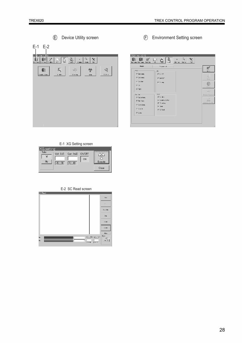
DEVICE UTILITYWhen you click on TREX on the Main Menu, the Device Utility screen is displayed. Device operation such as XG opera-tion and initialization can be performed.
①Sample collection Any samples remaining inside the device are collected. (See page 69)
② Initialization The device is initialized. (See page 69)
③XG setting The XG setting screen is displayed. XG-related operation can be performed. (See page 66)
④Aging The screen for aging of the X-ray tube is displayed.
⑤SC Read X-ray intensity display read by SC is displayed.This is used in adjustment, etc. after target replacement.
66
DEVICE UTILITYTREX620
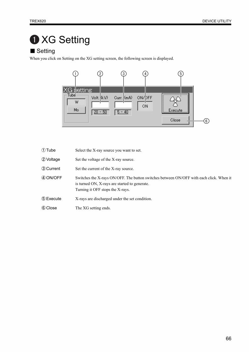
XG Setting■ SettingWhen you click on Setting on the XG setting screen, the following screen is displayed.
①Tube Select the X-ray source you want to set.
②Voltage Set the voltage of the X-ray source.
③Current Set the current of the X-ray source.
④ON/OFF Switches the X-rays ON/OFF. The button switches between ON/OFF with each click. When itis turned ON, X-rays are started to generate.Turning it OFF stops the X-rays.
⑤Execute X-rays are discharged under the set condition.
⑥Close The XG setting ends.
67
DEVICE UTILITYTREX620
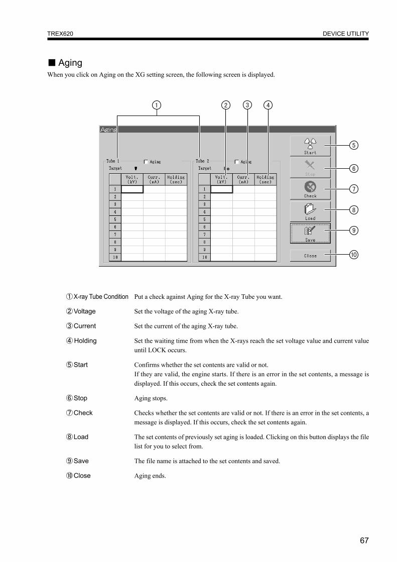
■ AgingWhen you click on Aging on the XG setting screen, the following screen is displayed.
①X-ray Tube Condition Put a check against Aging for the X-ray Tube you want.
②Voltage Set the voltage of the aging X-ray tube.
③Current Set the current of the aging X-ray tube.
④ Holding Set the waiting time from when the X-rays reach the set voltage value and current valueuntil LOCK occurs.
⑤Start Confirms whether the set contents are valid or not.If they are valid, the engine starts. If there is an error in the set contents, a message isdisplayed. If this occurs, check the set contents again.
⑥Stop Aging stops.
⑦Check Checks whether the set contents are valid or not. If there is an error in the set contents, amessage is displayed. If this occurs, check the set contents again.
⑧Load The set contents of previously set aging is loaded. Clicking on this button displays the filelist for you to select from.
⑨Save The file name is attached to the set contents and saved.
⑩Close Aging ends.
68
DEVICE UTILITYTREX620
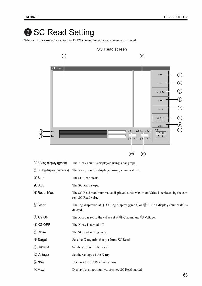
SC Read SettingWhen you click on SC Read on the TREX screen, the SC Read screen is displayed.
①SC log display (graph) The X-ray count is displayed using a bar graph.
②SC log display (numerals) The X-ray count is displayed using a numeral list.
③Start The SC Read starts.
④Stop The SC Read stops.
⑤Reset Max The SC Read maximum value displayed at ⑭ Maximum Value is replaced by the cur-rent SC Read value.
⑥Clear The log displayed at ① SC log display (graph) or ② SC log display (numerals) isdeleted.
⑦XG ON The X-ray is set to the value set at ⑪ Current and ⑫ Voltage.
⑧XG OFF The X-ray is turned off.
⑨Close The SC read setting ends.
⑩Target Sets the X-ray tube that performs SC Read.
⑪Current Set the current of the X-ray.
⑫Voltage Set the voltage of the X-ray.
⑬Now Displays the SC Read value now.
⑭Max Displays the maximum value since SC Read started.
69
DEVICE UTILITYTREX620
InitializeThis initializes the main unit. It is used to initialize the machine when it is in a non-initialized condition. When you click onthe Initialize button, a confirmation screen is displayed to confirm that you want to initialize.
Sample CollectionThis is used in situations such as when you reset the PC while there are still samples inside the machine. When you click onthe button, a confirmation screen is displayed to confirm that you want to collect the samples.

70
ENVIRONMENT SETTINGTREX620
ENVIRONMENT SETTINGWhen you click Environment Setting on the Main Menu, the Setting screen is displayed. By this function, some menu
items or analytical condition(recipe) can be set to protect miss-operation by unqualitied operator.
The setting contents are protected by a password, so changes cannot be made unless the password matches.
①Setting tab When you click on the respective tab button, the applicable setting screens appear.
②Edit Click here to change the setting contents. Input your password when the password input
screen is displayed. Once you have input the correct password you can change the setting
contents.
③Save The setting changes are saved. When you click on this button, a confirmation screen is
displayed to confirm that you want to make the changes.
④Check This checks that the setting contents are valid. If there is an error in the set contents, a
message is displayed. If this occurs, check the set contents again.
⑤Change Password Password This changes the password. Clicking here displays the password change screen.
Input your password in accordance with the screen instructions.
⑥Energy Calibration The screen for energy calibration is displayed (page 74). After you have made a change,restart the application.
●PASSWORD● When the machine is shipped from the factory, the password is set as "Technos".

71
ENVIRONMENT SETTINGTREX620
■ Setting Enable/Disable Display of Menu ButtonsWhen you click the Window tab on the Setting Menu, the following screen is displayed. This screen is for setting enable/
disable display of menu buttons.
Buttons that have a check mark against their name are displayed on each menu. Remove the check mark from the
name of any button that you do not want displayed. By not displaying specific buttons, you can set it so that the
function of that button can no longer be used and the set contents cannot be changed.

72
ENVIRONMENT SETTINGTREX620
■ Measurement SettingWhen you click the TREX tab on the Setting Menu, the following screen is displayed. On this screen you can set the X-ray
after the end of measurement and set the wafer alignment to orientation flat.
①XG after meas. This sets the X-ray power condition after measurement is completed. Target1 is for W,
target2 is for Mo.
OFF : After measurement, X-ray is OFF.Keep : After measurement, X-ray maintains the same condition as during measurement.MINIMUM(XG1) : When measurement is completed, Target 1 is set to minimum load.MINIMUM(XG2) : When measurement is completed, Target 2 is set to minimum load.
②Slot No. This sets whether the cassette Slot No. has No. 1 at the top or the bottom.
③Alignment This sets wafer aligner function such as O.F.(Orientation Flat), Notch, or None Align.
These settings works at the time of measurement. If None is selected, the wafer aligner isnot performed before measurement. For some special sample, None should be selected.
If you want to make a selection just before measurement, select "Decide Before Start
Meas.".
● When you want to perform high precision, fast measurement, set XG after meas. to "Keep".
73
ENVIRONMENT SETTINGTREX620
● Energy calibration coefficients calculationThis system performs peak fitting of measured data, so calibration of the energy axes and energy resolution is necessary.
Accordingly, perform calibration coefficients calculation in the following cases.
1. When the Solid State Detector (SSD) or linear amp is replaced.
2. When you reinstall the TREX system disk.
3. When the energy axis of the actual peak (black) and analysis peak (blue) do not match.
4. When there is a large difference in the peak width of the actual peak (black) and analysis peak (blue).
● Energy calibration coefficients calculation procedure
1. Load data in which only the Si peak and exciting X-rays (W, or Mo) are clearly indicated. (If there is peak
of large inparity, deviation occurs in calculation of coefficients.)
2. Click on ⑥Energy Calibration on page 70. The next page will be displayed.
● Do not perform this operation for the W and Mo beams on the twin beam machine (Trex620).

74
ENVIRONMENT SETTINGTREX620
①X-ray Tube Select the energy calibration display and the X-ray tube for editing. By switching the itemshere, each reset value and system value changes.
②Calibration Value Set Each item displays the following contents.Reset Value :Reset value.
System Value :Currently used calibration value.
Calculated Value :The calibration value calculated based on the read file. The file is readwhen the Open command is given, and the value is displayed onlywhen the calibration value is calculated successfully.
File Value :The calibration value held by the read file is displayed. It is displayedwhen the file has been read.
③Data Display Area The file selected at ⑤ Open is displayed.
④Half Value Width Displays the half-value width for the selected calibration value set.
⑤Open Opens the measurement file.
⑥Close Closes the open file.
⑦Update (File Value) Upgrades the calibration value of the open file for the selected calibration value set.
⑧Update (System) Upgrades the calibration value of the system for the selected calibration value set.
⑨End Finishes energy calibration.
⑩Data Display Settings Settings for display of measurement data. See Profile for One Point Analysis (page 55).

75
MONITORTREX620
MONITORWhen you click Monitor on the Main Menu, the Monitor screen is activated. If it is already in operation, the Monitor screenis displayed at the front. Clicking on the buttons at the top of the screen will display the applicable screen.
76
MONITORTREX620
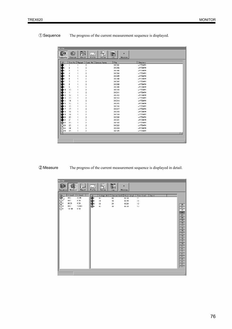
①Sequence The progress of the current measurement sequence is displayed.
②Measure The progress of the current measurement sequence is displayed in detail.

77
MONITORTREX620
③Result The Last Result and the History of Results are displayed.
④Profile The observed waveform and its measurement parameters are displayed.
78
MONITORTREX620
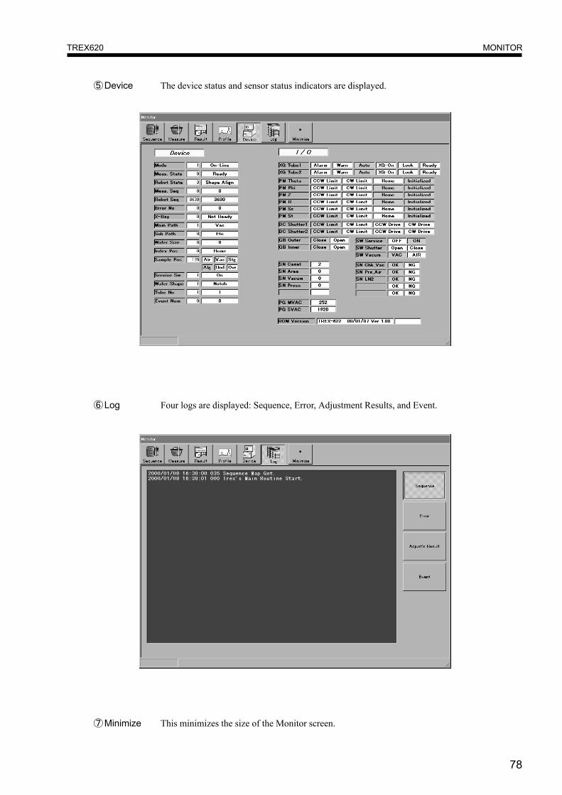
⑥Log Four logs are displayed: Sequence, Error, Adjustment Results, and Event.
⑤Device The device status and sensor status indicators are displayed.
⑦Minimize This minimizes the size of the Monitor screen.

79
MEASUREMENT METHODTREX620
MEASUREMENT METHODSet the Wafer Cassette
1. Set the wafer cassette containing wafers upon the cassette base. Then set the wafer pod cover over the wafer pod.

80
MEASUREMENT METHODTREX620
Measurement Execution■ Easy MeasurementJust by selecting preset measurement conditions and the Data Directory for measurement data, operations from measure-ment to analysis can be performed.
1. Click Easy meas. on the Main Menu.The Easy measurement screen will be displayed.
2. Using the Recipe condition button to select a preset Recipe condition.3. Use the Data Directory button to select the Data Directory for saving the measurement data.4. Input the Sample name and Operator name. (Measurement can be performed without these.)5. Specify the wafer alignment (Only when “Setting of Wafer Alignment” is set to “Decide Before Start Meas.” on
the Setting screen, See page 70.)6. When you click Start, measurement will start.
● With the date and number the measurement data is automatically assigned a file name. This cannot be changed.● When the sample name is input, the same sample name is applied to all the applicable measurement results.● To cancel measurement, click on Stop. Measurement will then stop and samples inside the machine will automati-
cally be recovered. When you click on Start, measurement will start again from the beginning.

81
MEASUREMENT METHODTREX620
■ Continuous MeasurementA different analytical condition can be applied to each wafer, or the analytical condition can be changed any number oftimes and applied to the same wafer.
1. Click on Cont. meas. on the Main Menu.The Continuous measurement screen will be displayed.
2. Input the Operator name. (Measurement can be performed without inputting this.)3. Click on the Data Directory button and select the Data Directory.4. Input the Slot No. where the wafer is that you want to measure.5. Set the number of operation Repeats, Recipe Condition, File name, Data Directory and Sample name.
※ Input the Data Directory when you want to save the data at a place other than the directory selected by the DataDirectory selection buttons. Measurement can be performed without inputting the sample name.
6. Put a check mark against the rows you want to process.7. Specify the wafer alignment (Only when “Setting of Wafer Alignment” is set to “Decide Before Start Meas.” on
the Setting screen, See page 70.)8. When you click Start, the parameter check is performed and if the set contents are valid, measurement will start.
● If the set contents are invalid, a message is displayed at the time for measurement start. If this occurs, check the setcontents again.
● To cancel measurement, click on Stop. Measurement will then stop and samples inside the machine will automati-cally be recovered. When you click on Start, measurement will start again from the beginning.
82
MEASUREMENT METHODTREX620
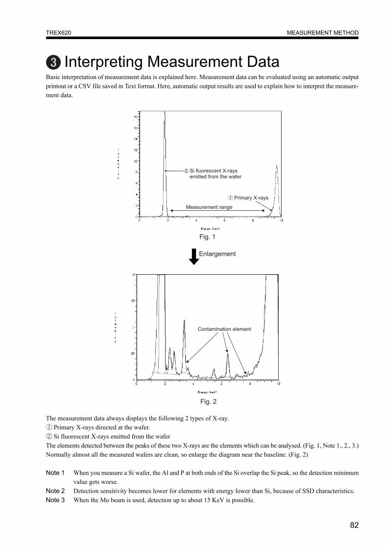
Interpreting Measurement DataBasic interpretation of measurement data is explained here. Measurement data can be evaluated using an automatic outputprintout or a CSV file saved in Text format. Here, automatic output results are used to explain how to interpret the measure-ment data.
The measurement data always displays the following 2 types of X-ray.① Primary X-rays directed at the wafer.② Si fluorescent X-rays emitted from the waferThe elements detected between the peaks of these two X-rays are the elements which can be analysed. (Fig. 1, Note 1., 2., 3.)Normally almost all the measured wafers are clean, so enlarge the diagram near the baseline. (Fig. 2)
Note 1 When you measure a Si wafer, the Al and P at both ends of the Si overlap the Si peak, so the detection minimumvalue gets worse.
Note 2 Detection sensitivity becomes lower for elements with energy lower than Si, because of SSD characteristics.Note 3 When the Mo beam is used, detection up to about 15 KeV is possible.
83
MEASUREMENT METHODTREX620
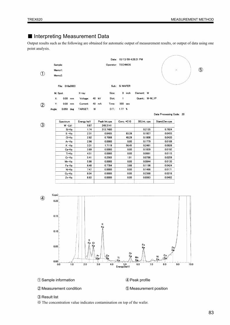
■ Interpreting Measurement DataOutput results such as the following are obtained for automatic output of measurement results, or output of data using onepoint analysis.
①Sample information
②Measurement condition
③Result list※ The concentration value indicates contamination on top of the wafer.
④Peak profile
⑤Measurement position
①
②
③
④
⑤
84
X-RAY CONTROLLERTREX620
X-RAY CONTROLLER
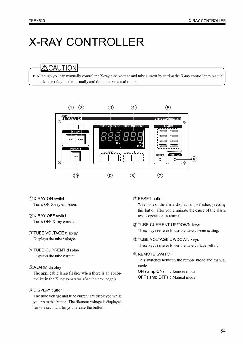
● Although you can manually control the X-ray tube voltage and tube current by setting the X-ray controller to manualmode, use relay mode normally and do not use manual mode.
①X-RAY ON switchTurns ON X-ray emission.
②X-RAY OFF switchTurns OFF X-ray emission.
③TUBE VOLTAGE displayDisplays the tube voltage.
④TUBE CURRENT displayDisplays the tube current.
⑤ALARM displayThe applicable lamp flashes when there is an abnor-mality in the X-ray generator. (See the next page.)
⑥DISPLAY buttonThe tube voltage and tube current are displayed whileyou press this button. The filament voltage is displayedfor one second after you release the button.
⑦RESET buttonWhen one of the alarm display lamps flashes, pressingthis button after you eliminate the cause of the alarmresets operation to normal.
⑧TUBE CURRENT UP/DOWN keysThese keys raise or lower the tube current setting.
⑨TUBE VOLTAGE UP/DOWN keysThese keys raise or lower the tube voltage setting.
⑩REMOTE SWITCHThis switches between the remote mode and manualmode.ON (lamp ON) : Remote modeOFF (lamp OFF) : Manual mode
85
X-RAY CONTROLLERTREX620
■ Alarm DisplayThe alarm display lights up when the following abnormalities occur.
OVL : The tube voltage exceeds the upper limit.LVL : The tube voltage drops below the lower limit.OCL : The tube current exceeds the upper limit.OLL : Abnormal overload has been applied to the X-ray tube.OH : Overheating of the X-ray generatorCW : Coolant water flow is insufficient or the safety circuit is activated.SFTY : The X-ray exposure prevention circuit is activated.W. LEAK : Coolant water leak.
■ Error DisplayIf an error occurs during the start up of the tube voltage or tube current, the X-ray controller indicates the error on the tubevoltage display and tube current display. Pushing the reset button extinguishes the display.
Err10 : X-RAY ON does not occur for the XG body.If the alarm flashes simultaneously, it is not an error with the X-ray generator.Cause : Cable fault, connector disconnection, etc. between controller and XG
Err11 : Tube voltage is not applied. (Timeout: 15 seconds)Cause : Cable fault, connector disconnection, etc. between controller and XG; XG operating fault, etc.
Err12 : Tube current is not applied. (Timeout: 60 seconds)Cause : Filament break in vessel. High voltage cable faulty, faulty contact, etc.
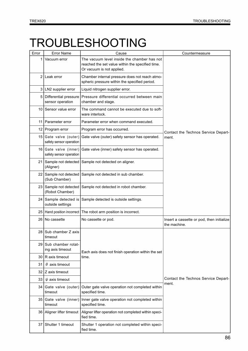
86
TROUBLESHOOTINGTREX620
TROUBLESHOOTINGThe vacuum level inside the chamber has notreached the set value within the specified time.Or vacuum is not applied.
Chamber internal pressure does not reach atmo-spheric pressure within the specified period.
Liquid nitrogen supplier error.
Pressure differential occurred between mainchamber and stage.
The command cannot be executed due to soft-ware interlock.
Parameter error when command executed.
Program error has occurred.
Gate valve (outer) safety sensor has operated.
Gate valve (inner) safety sensor has operated.
Sample not detected on aligner.
Sample not detected in sub chamber.
Sample not detected in robot chamber.
Sample detected is outside settings.
The robot arm position is incorrect.
No cassette or pod.
Each axis does not finish operation within the settime.
Outer gate valve operation not completed withinspecified time.
Inner gate valve operation not completed withinspecified time.
Aligner lifter operation not completed within speci-fied time.
Shutter 1 operation not completed within speci-fied time.
1 Vacuum error
2 Leak error
3 LN2 supplier error
5 Differential pressuresensor operation
10 Sensor value error
11 Parameter error
12 Program error
15 Gate valve (outer)safety sensor operation
16 Gate valve ( inner)safety sensor operation
21 Sample not detected(Aligner)
22 Sample not detected(Sub Chamber)
23 Sample not detected(Robot Chamber)
24 Sample detected isoutside settings
25 Hand position incorrect
26 No cassette
28 Sub chamber Z axistimeout
29 Sub chamber rotat-ing axis timeout
30 R axis timeout
31 θ axis timeout
32 Z axis timeout
33 ψ axis timeout
34 Gate valve (outer)timeout
35 Gate valve (inner)timeout
36 Aligner lifter timeout
37 Shutter 1 timeout
Contact the Technos Service Depart-ment.
Insert a cassette or pod, then initializethe machine.
Contact the Technos Service Depart-ment.
Error Name Cause CountermeasureError
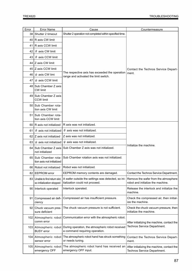
87
TROUBLESHOOTINGTREX620
38 Shutter 2 timeout
40 R axis CW limit
41 R axis CCW limit
42 θ axis CW limit
43 θ axis CCW limit
44 Z axis CW limit
45 Z axis CCW limit
46 ψ axis CW limi
47 ψ axis CCW limit
48 Sub Chamber Z axisCW limit
49 Sub Chamber Z axisCCW limit
50 Sub Chamber rota-tion axis CW limit
51 Sub Chamber rota-tion axis CCW limit
60 R axis not initialized
61 θ axis not initialized
62 Z axis not initialized
63 ψ axis not initialized
64 Sub Chamber Z axisnot initialized
65 Sub Chamber rota-tion axis not initialized
66 Robot not initialized
82 EEPROM error
83 Unable to find return slot,so initialization stopped
90 Interlock operated
91 Compressed air defi-ciency
92 Chuck vacuum pres-sure deficient
102 Atmospheric robotcomm error
103 Atmospheric robotBUSY error
104 Atmospheric robotsensor error
105 Atmospheric robotemergency OFF
Shutter 2 operation not completed within specified time.
The respective axis has exceeded the operationrange and activated the limit switch.
R axis was not initialized.
θ axis was not initialized.
Z axis was not initialized.
ψ axis was not initialized.
Sub Chamber Z axis was not initialized.
Sub Chamber rotation axis was not initialized.
Robot was not initialized.
EEPROM memory contents are damaged.
A wafer outside the settings was detected, so ini-tialization could not proceed.
Interlock operated.
Compressed air has insufficient pressure.
The chuck vacuum pressure is not sufficient.
Communication error with the atmospheric robot.
During operation, the atmospheric robot receiveda command requiring operation.
The atmospheric robot hand has struck somethingor needs tuning.
The atmospheric robot hand has received anemergency OFF input.
Contact the Technos Service Depart-ment.
Initialize the machine.
Contact the Technos Service Department.
Remove the wafer from the atmosphererobot and initialize the machine.
Release the interlock and initialize themachine.
Check the compressed air, then initial-ize the machine.
Check the chuck vacuum pressure, theninitialize the machine.
After initializing the machine, contact theTechnos Service Department.
Contact the Technos Service Depart-ment.
After initializing the machine, contact theTechnos Service Department.
Error Name Cause CountermeasureError
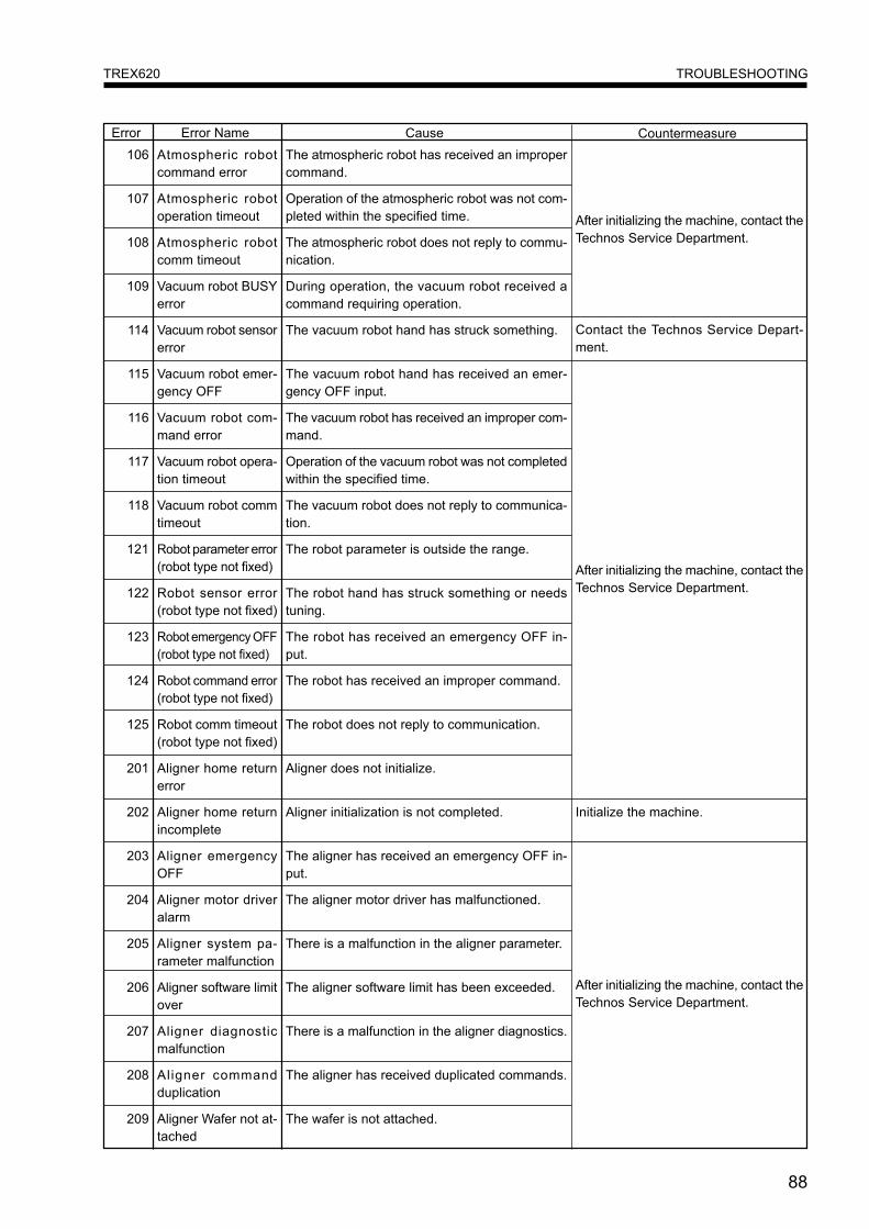
88
TROUBLESHOOTINGTREX620
106 Atmospheric robotcommand error
107 Atmospheric robotoperation timeout
108 Atmospheric robotcomm timeout
109 Vacuum robot BUSYerror
114 Vacuum robot sensorerror
115 Vacuum robot emer-gency OFF
116 Vacuum robot com-mand error
117 Vacuum robot opera-tion timeout
118 Vacuum robot commtimeout
121 Robot parameter error(robot type not fixed)
122 Robot sensor error(robot type not fixed)
123 Robot emergency OFF(robot type not fixed)
124 Robot command error(robot type not fixed)
125 Robot comm timeout(robot type not fixed)
201 Aligner home returnerror
202 Aligner home returnincomplete
203 Aligner emergencyOFF
204 Aligner motor driveralarm
205 Aligner system pa-rameter malfunction
206 Aligner software limitover
207 Aligner diagnosticmalfunction
208 Aligner commandduplication
209 Aligner Wafer not at-tached
The atmospheric robot has received an impropercommand.
Operation of the atmospheric robot was not com-pleted within the specified time.
The atmospheric robot does not reply to commu-nication.
During operation, the vacuum robot received acommand requiring operation.
The vacuum robot hand has struck something.
The vacuum robot hand has received an emer-gency OFF input.
The vacuum robot has received an improper com-mand.
Operation of the vacuum robot was not completedwithin the specified time.
The vacuum robot does not reply to communica-tion.
The robot parameter is outside the range.
The robot hand has struck something or needstuning.
The robot has received an emergency OFF in-put.
The robot has received an improper command.
The robot does not reply to communication.
Aligner does not initialize.
Aligner initialization is not completed.
The aligner has received an emergency OFF in-put.
The aligner motor driver has malfunctioned.
There is a malfunction in the aligner parameter.
The aligner software limit has been exceeded.
There is a malfunction in the aligner diagnostics.
The aligner has received duplicated commands.
The wafer is not attached.
After initializing the machine, contact theTechnos Service Department.
After initializing the machine, contact theTechnos Service Department.
Initialize the machine.
After initializing the machine, contact theTechnos Service Department.
Contact the Technos Service Depart-ment.
Error Name Cause CountermeasureError

89
TROUBLESHOOTINGTREX620
210 Aligner control lermalfunction
211 Aligner centeringmalfunction
212 Aligner O.F. align-ment malfunction
213 Aligner lifter up/downmalfunction
216 Aligner not ready
217 Aligner time over
218 Aligner sequence error
219 Aligner answer error
300 Port comm error
301 Port command error
302 Port BUSY error
303 Port Load error
304 Port Unload error
305 Port Lock error
306 Port Unlock error
307 Port Slot movementerror
308 Port inching error
309 Port map acquisitionerror
310 Port initialization error
311 P o r t o p e r a t i o ntimeout
312 Port comm timeout
313 Port parameter error
314 Port not initialized
315 Port event time out
316 Port ACK time out 1
317 Port ACK time out 2
318 Port secondary mes-sage time out
The aligner controller has malfunctioned.
The wafer shape setting is wrong.
The aligner lifter is not operating.
The aligner controller is not responding.
The aligner operation is not completed within thespecified time.
There is a malfunction in the aligner sequence.
The parameter cannot be set for the aligner.
The port has cancelled communication.
The command to the port was not appropriate.
During operation, a command requiring operationwas received.
There was a failure loading the cassette.
There was a failure unloading the cassette.
There was a failure locking the pod.
There was a failure unlocking the pod.
There was a failure moving to the specified slot.
There was a failure in inching the cassette.
There was a failure in acquiring the wafer map.
There was a failure in port initialization.
Port operation is not completed within the speci-fied time.
The port does not reply to communication.
The port parameter is outside the range.
The port is not initialized.
The event report has not been received from the port.
No acknowledgment has come from the port.
No secondary message has come from the port.
After initializing the machine, contact theTechnos Service Department.
Initialize the machine.
After initializing the machine, contact theTechnos Service Department.
After initializing the machine, contact theTechnos Service Department.
Check the wafer shape setting.
Check the pressure of the compressedair.
Error Name Cause CountermeasureError
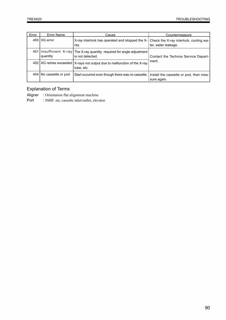
90
TROUBLESHOOTINGTREX620
450 XG error
451 Insuff icient X-rayquantity
452 XG retries exceeded
454 No cassette or pod
Explanation of TermsAligner : Orientation flat alignment machinePort : SMIF. etc, cassette inlet/outlet, elevator.
Error Name Cause CountermeasureErrorX-ray interlock has operated and stopped the X-ray.
The X-ray quantity required for angle adjustmentis not detected.
X-rays not output due to malfunction of the X-raytube, etc.
Start occurred even though there was no cassette.
Check the X-ray interlock, cooling wa-ter, water leakage.
Contact the Technos Service Depart-ment.
Install the cassette or pod, then mea-sure again.
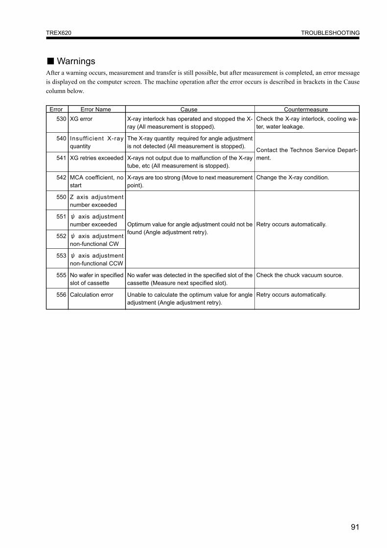
91
TROUBLESHOOTINGTREX620
530 XG error
540 Insuff icient X-rayquantity
541 XG retries exceeded
542 MCA coefficient, nostart
550 Z axis adjustmentnumber exceeded
551 ψ axis adjustmentnumber exceeded
552 ψ axis adjustmentnon-functional CW
553 ψ axis adjustmentnon-functional CCW
555 No wafer in specifiedslot of cassette
556 Calculation error
X-ray interlock has operated and stopped the X-ray (All measurement is stopped).
The X-ray quantity required for angle adjustmentis not detected (All measurement is stopped).
X-rays not output due to malfunction of the X-raytube, etc (All measurement is stopped).
X-rays are too strong (Move to next measurementpoint).
Optimum value for angle adjustment could not befound (Angle adjustment retry).
No wafer was detected in the specified slot of thecassette (Measure next specified slot).
Unable to calculate the optimum value for angleadjustment (Angle adjustment retry).
■ WarningsAfter a warning occurs, measurement and transfer is still possible, but after measurement is completed, an error messageis displayed on the computer screen. The machine operation after the error occurs is described in brackets in the Causecolumn below.
Check the X-ray interlock, cooling wa-ter, water leakage.
Contact the Technos Service Depart-ment.
Change the X-ray condition.
Retry occurs automatically.
Check the chuck vacuum source.
Retry occurs automatically.
Error Name Cause CountermeasureError

92
DAILY INSPECTION AND PERIODIC INSPECTIONTREX620
DAILY INSPECTION AND PERIODIC INSPECTIONDaily Inspection
Check the following items in your daily inspection.
● Trex620 Main Body● The cooling water flow rate must be 3 L/min.● The nitrogen gas, compressed air, cooling water and wafer chuck vacuum, etc. must be flowing at the specified value
or above.● The remaining capacity of the liquid nitrogen on the SSD side must be 20% or more.● Check that there is no alarm display illuminated on the XG operation panel.
● Liquid Nitrogen Supplier● Check that there is no alarm display illuminated on the operation panel.● The nitrogen gas flow rate must be 3 L/min.
Periodic Inspection● Monthly InspectionCheck the following items monthly.
● Trex620 Main BodyX-ray Intensity CheckMeasure the supplied standard sample and check the integrated intensity value of contamination elements (particularly Ni-ka). (Use the intensity at the time of purchase as a reference value for the integrated intensity value, and if the integratedintensity value changes more than ± 15% of the integrated intensity value at the time of purchase, contact the TechnosService Department.)
Special Direct X-ray Intensity CheckPeriodically check the direct X-ray intensity value (SC Read value).(Use the intensity at the time of purchase as a reference value for the SC Read value, and if the value changes more than± 10% of the value at the time of purchase, contact the Technos Service Department.)
● Periodic Inspection on a Chargeable BasisTechnos provides a periodic inspection twice a year for a fee. The X-ray intensity check and transport system check isperformed beforehand. Contact Technos to request a periodic inspection.

93
DAILY INSPECTION AND PERIODIC INSPECTIONTREX620
This value is for almost continuous operation of the X-ray tube. When use is intermittent, or there are long periods of standby use at low output, the period is longer.
Periodic Replacement Parts
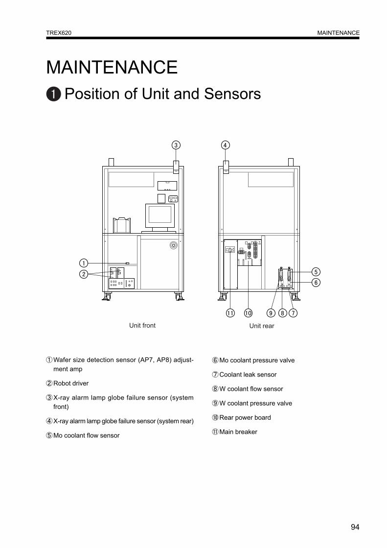
94
MAINTENANCETREX620
MAINTENANCEPosition of Unit and Sensors
①Wafer size detection sensor (AP7, AP8) adjust-ment amp
②Robot driver
③X-ray alarm lamp globe failure sensor (systemfront)
④X-ray alarm lamp globe failure sensor (system rear)
⑤Mo coolant flow sensor
⑥Mo coolant pressure valve
⑦Coolant leak sensor
⑧W coolant flow sensor
⑨W coolant pressure valve
⑩Rear power board
⑪Main breaker

95
MAINTENANCETREX620
⑫M hour meter
⑬ W hour meter
⑭Signal lamp driver
⑮XG controller
⑯Circuit breaker (for clean unit fan)
⑰CPU rack
⑱Valve driver
⑲Safety circuit
⑳Driver rack (for SSR, pulse drive)
Power unit
Wafer chuck vacuum switch
Compressed air pressure switch
Power for oxygen concentration meter
Measurement rack
Aligner driver
XG controller
XG high pressure tank
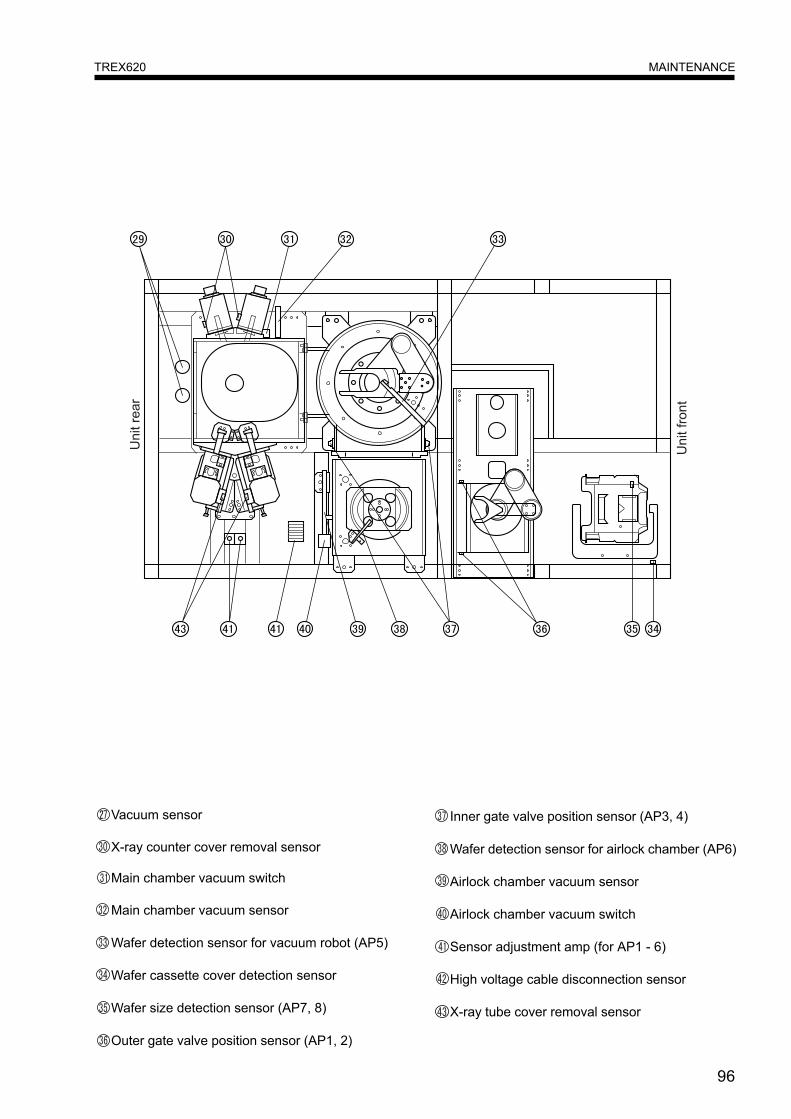
96
MAINTENANCETREX620
Vacuum sensor
X-ray counter cover removal sensor
Main chamber vacuum switch
Main chamber vacuum sensor
Wafer detection sensor for vacuum robot (AP5)
Wafer cassette cover detection sensor
Wafer size detection sensor (AP7, 8)
Outer gate valve position sensor (AP1, 2)
Inner gate valve position sensor (AP3, 4)
Wafer detection sensor for airlock chamber (AP6)
Airlock chamber vacuum sensor
Airlock chamber vacuum switch
Sensor adjustment amp (for AP1 - 6)
High voltage cable disconnection sensor
X-ray tube cover removal sensor

97
MAINTENANCETREX620
Adjustment Method of Sensors, Vacuum Switches and Pressure Switches■ Optical Sensors
Outer gate valvepinch preventionOuter gate valvepinch preventionInner gate valvepinch preventionInner gate valvepinch preventionWafer detection
Wafer detection
6 inch cassette de-tection8 inch cassette de-tection
Sefety sensor(outer,upper)Sefety sensor(outer,lower)Sefety sensor(inner,upper)Sefety sensor(inner,lower)Robot ChamberWafer Det3Sub ChamberWafer Det6`Wafer size Dat
8`Wafer size Dat
2 point tuning
2 point tuning
2 point tuning
2 point tuning
Maximum sensitiv-ity adjustmentMaximum sensitiv-ity adjustment2 point tuning
2 point tuning
Logic Red LED ONconditionSym. Application Sticker Adjustment Method Type Sensi-
tivityTransmission type
Transmission type
Transmission type
Transmission type
Reflection type
Transmission type
Reflection type
Reflection type
Fine
Fine
Fine
Fine
Turbo
Fine
Fine
Fine
D-ON
D-ON
D-ON
D-ON
D-ON
L-ON
L-ON
L-ON
AP1
AP2
AP3
AP4
AP5
AP6
AP7
AP8
Obstacle present
Obstacle present
Obstacle present
Obstacle present
No wafer
No wafer
Cassette present
Cassette present
● Optical Sensor Adjustment MethodOpen the transparent cover of the optical sensor, then perform adjustment.AP1 - AP4
1. Set work (applicable item such as a cassette or wafer) in position. Press the SET button. The yellow LED comesON.
2. Press the ON switch of the distribution board.AP5
1. Do not put anything under the sensor. Press the SET button for at least 3 seconds.2. Release your finger after the yellow LED flashes.
AP61. Set work in position. Press the SET button for at least 3 seconds.2. Release your finger after the yellow LED flashes.
AP7-AP81. Set work in position. Press the SET button. The yellow LED comes ON.2. Remove the work. Press the SET button. The yellow LED turns OFF.
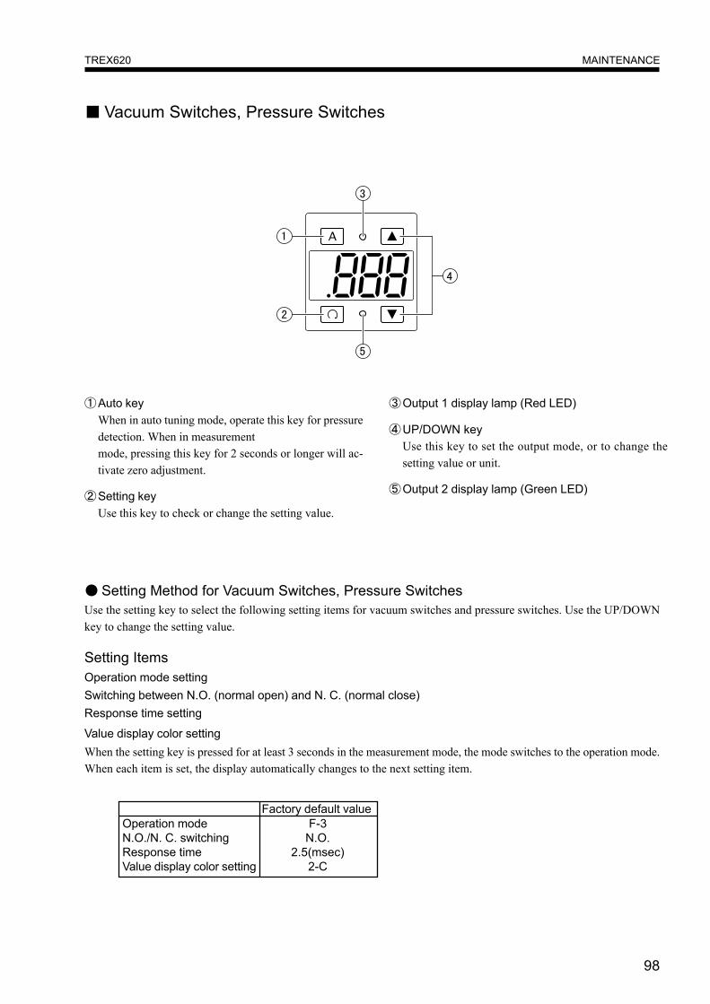
98
MAINTENANCETREX620
■ Vacuum Switches, Pressure Switches
①Auto keyWhen in auto tuning mode, operate this key for pressuredetection. When in measurementmode, pressing this key for 2 seconds or longer will ac-tivate zero adjustment.
②Setting keyUse this key to check or change the setting value.
③Output 1 display lamp (Red LED)
④UP/DOWN keyUse this key to set the output mode, or to change thesetting value or unit.
⑤Output 2 display lamp (Green LED)
● Setting Method for Vacuum Switches, Pressure SwitchesUse the setting key to select the following setting items for vacuum switches and pressure switches. Use the UP/DOWNkey to change the setting value.
Setting ItemsOperation mode settingSwitching between N.O. (normal open) and N. C. (normal close)Response time setting
Value display color settingWhen the setting key is pressed for at least 3 seconds in the measurement mode, the mode switches to the operation mode.When each item is set, the display automatically changes to the next setting item.
Operation modeN.O./N. C. switchingResponse timeValue display color setting
Factory default valueF-3
N.O.2.5(msec)
2-C
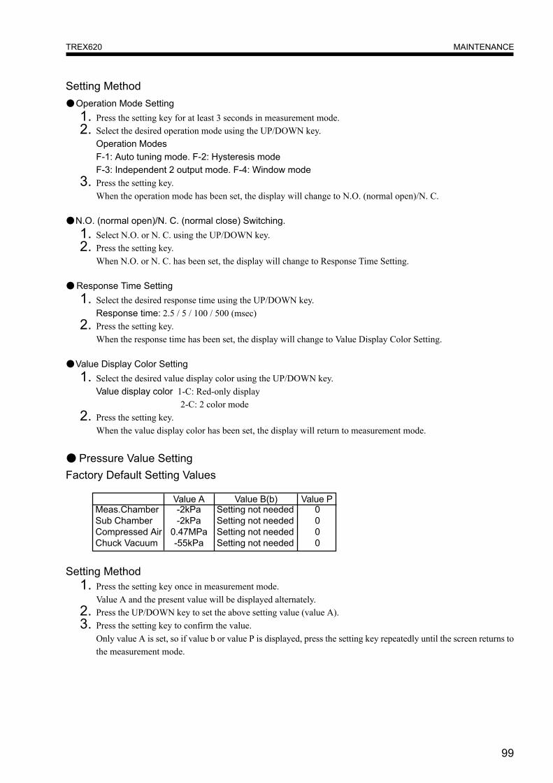
99
MAINTENANCETREX620
Setting Method●Operation Mode Setting
1. Press the setting key for at least 3 seconds in measurement mode.2. Select the desired operation mode using the UP/DOWN key.
Operation ModesF-1: Auto tuning mode. F-2: Hysteresis modeF-3: Independent 2 output mode. F-4: Window mode
3. Press the setting key.When the operation mode has been set, the display will change to N.O. (normal open)/N. C.
●N.O. (normal open)/N. C. (normal close) Switching.1. Select N.O. or N. C. using the UP/DOWN key.2. Press the setting key.
When N.O. or N. C. has been set, the display will change to Response Time Setting.
●Response Time Setting1. Select the desired response time using the UP/DOWN key.
Response time: 2.5 / 5 / 100 / 500 (msec)2. Press the setting key.
When the response time has been set, the display will change to Value Display Color Setting.
●Value Display Color Setting1. Select the desired value display color using the UP/DOWN key.
Value display color 1-C: Red-only display 2-C: 2 color mode
2. Press the setting key.When the value display color has been set, the display will return to measurement mode.
● Pressure Value SettingFactory Default Setting Values
Meas.ChamberSub ChamberCompressed AirChuck Vacuum
Value A-2kPa-2kPa
0.47MPa-55kPa
Value B(b)Setting not neededSetting not neededSetting not neededSetting not needed
0000
Value P
Setting Method1. Press the setting key once in measurement mode.
Value A and the present value will be displayed alternately.2. Press the UP/DOWN key to set the above setting value (value A).3. Press the setting key to confirm the value.
Only value A is set, so if value b or value P is displayed, press the setting key repeatedly until the screen returns tothe measurement mode.
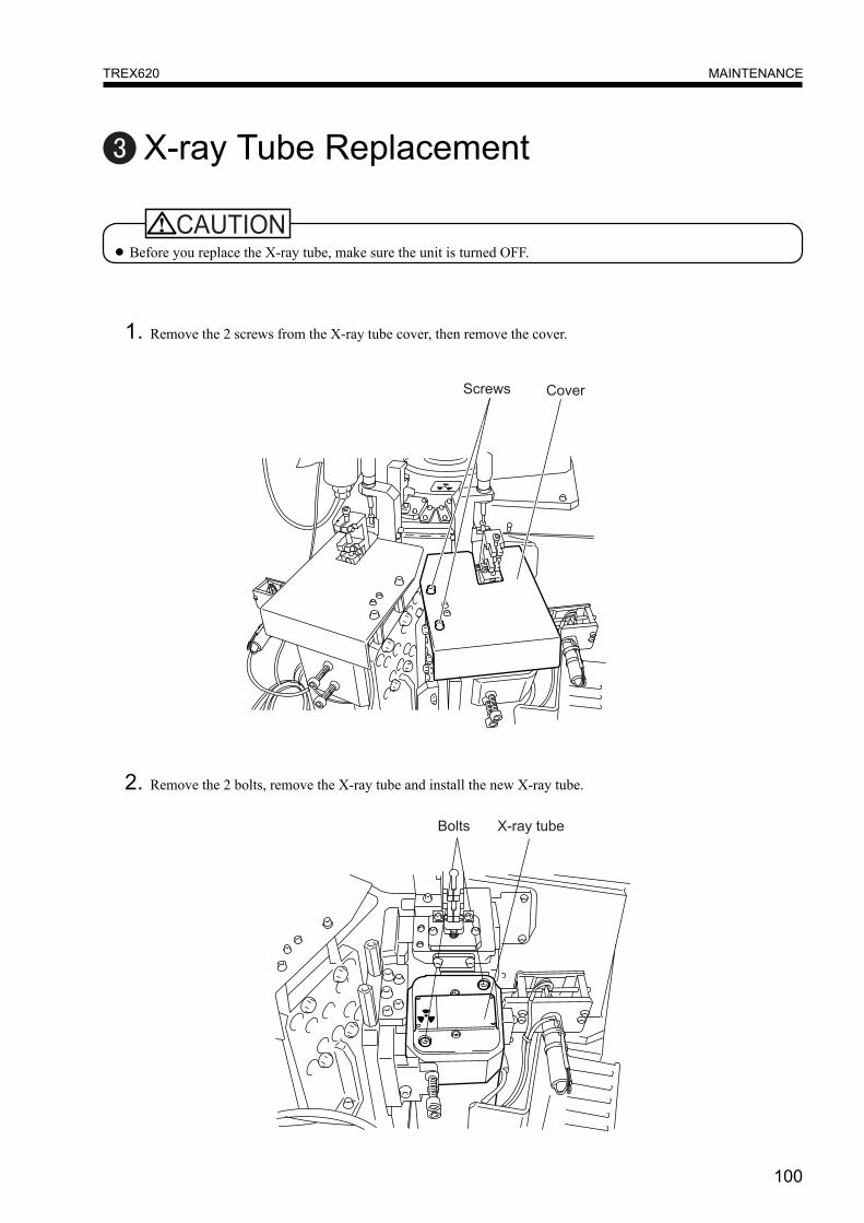
100
MAINTENANCETREX620
X-ray Tube Replacement
● Before you replace the X-ray tube, make sure the unit is turned OFF.
2. Remove the 2 bolts, remove the X-ray tube and install the new X-ray tube.
1. Remove the 2 screws from the X-ray tube cover, then remove the cover.

101
WARRANTYThis machine is covered by warranty for a period of one year from the date of purchase.
Even if the warranty period is still valid, machine malfunction for the following reasons shall be excluded from warranty
coverage.
1. Abnormal conditions caused by natural disasters and fires, etc.
2. Use of this machine for purposes it was not originally designed for.
3. Problems caused by unauthorized modification of this machine without the operator or a third party consulting
with the manufacturer.
4. Problems caused by installation conditions greatly different to those prescribed.
5. Gross negligence (including machine breakdown due to operation error) or intentional misuse by the operator or
third parties.
6. Wear of consumable items or the natural life of parts.
7. Breakdown caused by computer operation or malfunction.
8. Damage to the contents of computer memory devices.
9. Other malfunctions which cannot be considered the responsibility of Technos.
WARRANTYTREX620

102
REVISION RECORD
REVISION RECORDTREX620