Embed Size (px)
Citation preview

Operation and Safety ManualOriginal Instructions - Keep this manual with the machine at all times.
ANSI
Model260MRT
3121219June 29, 2018 - Rev I

WARNINGOperating, servicing and maintaining this vehicle or equipmentcan expose you to chemicals including engine exhaust, carbonmonoxide, phthalates, and lead, which are known to the State ofCalifornia to cause cancer and birth defects or otherreproductive harm. To minimize exposure, avoid breathingexhaust, do not idle the engine except as necessary, service yourvehicle or equipment in a well-ventilated area and wear glovesor wash your hands frequently when servicing. For moreinformation go to www.P65Warnings.ca.gov.

FOREWORD
FOREWORD
This manual is a very important tool! Keep it with the machine at all times.
The purpose of this manual is to provide owners, users, operators, lessors, and lessees with the precautions andoperating procedures essential for the safe and proper machine operation for its intended purpose.
Due to continuous product improvements, JLG Industries, Inc. reserves the right to make specification changeswithout prior notification. Contact JLG Industries, Inc. for updated information.
3121219 – JLG Lift – a

FOREWORD
SAFETY ALERT SYMBOLS AND SAFETY SIGNAL WORDS
INDICATES AN IMMINENTLY HAZARDOUS SITUATION. IFNOT AVOIDED, WILL RESULT IN SERIOUS INJURY ORDEATH. THIS DECAL WILL HAVE A RED BACKGROUND.
INDICATES A POTENTIALITY HAZARDOUS SITUATION. IFNOT AVOIDED, COULD RESULT IN SERIOUS INJURY ORDEATH. THIS DECAL WILL HAVE AN ORANGE BACK-GROUND.
INDICATES A POTENTIALITY HAZARDOUS SITUATION. IFNOT AVOIDED, MAY RESULT IN MINOR OR MODERATEINJURY. IT MAY ALSO ALERT AGAINST UNSAFE PRAC-TICES. THIS DECAL WILL HAVE A YELLOW BACK-GROUND.
INDICATES INFORMATION OR A COMPANY POLICY THATRELATES DIRECTLY OR INDIRECTLY TO THE SAFETY OFPERSONNEL OR PROTECTION OF PROPERTY.
This is the Safety Alert Symbol. It is used to alert you to the potential personalinjury hazards. Obey all safety messages that follow this symbol to avoid possibleinjury or death
b – JLG Lift – 3121219

FOREWORD
THIS PRODUCT MUST COMPLY WITH ALL SAFETYRELATED BULLETINS. CONTACT JLG INDUSTRIES, INC.OR THE LOCAL AUTHORIZED JLG REPRESENTATIVE FORINFORMATION REGARDING SAFETY-RELATED BULLE-TINS WHICH MAY HAVE BEEN ISSUED FOR THIS PROD-UCT.
JLG INDUSTRIES, INC. SENDS SAFETY RELATED BULLE-TINS TO THE OWNER OF RECORD OF THIS MACHINE.CONTACT JLG INDUSTRIES, INC. TO ENSURE THAT THECURRENT OWNER RECORDS ARE UPDATED AND ACCU-RATE.
JLG INDUSTRIES, INC. MUST BE NOTIFIED IMMEDIATELYIN ALL INSTANCES WHERE JLG PRODUCTS HAVE BEENINVOLVED IN AN ACCIDENT INVOLVING BODILY INJURYOR DEATH OF PERSONNEL OR WHEN SUBSTANTIALDAMAGE HAS OCCURRED TO PERSONAL PROPERTY ORTHE JLG PRODUCT.
Contact:Product Safety and Reliability DepartmentJLG Industries, Inc.1 JLG DriveMcConnellsburg, PA 17233
or Your Local JLG Office(See addresses on inside of manual cover)
In USA:Toll Free: 877-JLG-SAFE (877-554-7233)
Outside USA:Phone: 717-485-5161E-mail: [email protected]
For:• Accident Reporting
• Product Safety Publica-tions
• Current Owner Updates
• Questions Regarding Product Safety
• Standards and Regulations Compliance Information
• Questions Regarding Spe-cial Product Applications
• Questions Regarding Prod-uct Modifications
3121219 – JLG Lift – c

FOREWORD
REVISION LOG
Original Issue A - June 27, 2005
Revised B - July 17, 2006
Revised C - March 29, 2007
Revised D - October 22, 2008
Revised E - April 15, 2010
Revised F - May 14, 2010
Revised G - June 5, 2012
Revised H - April 28, 2017
Revised I - June 29, 2018 - Revised Covers, Prop 65
d – JLG Lift – 3121219

TABLE OF CONTENTS
SECTION - PARAGRAPH, SUBJECT PAGE SECTION - PARAGRAPH, SUBJECT PAGE
SECTION - 1 - SAFETY PRECAUTIONS
1.1 GENERAL . . . . . . . . . . . . . . . . . . . . . . . . . . . . . . . . .1-11.2 PRE-OPERATION . . . . . . . . . . . . . . . . . . . . . . . . . . .1-1
Operator Training and Knowledge. . . . . . . . . . . 1-1Workplace Inspection. . . . . . . . . . . . . . . . . . . . . 1-2Machine Inspection . . . . . . . . . . . . . . . . . . . . . . 1-4
1.3 OPERATION . . . . . . . . . . . . . . . . . . . . . . . . . . . . . . .1-4General . . . . . . . . . . . . . . . . . . . . . . . . . . . . . . . . 1-4Trip and Fall Hazards . . . . . . . . . . . . . . . . . . . . . 1-5Electrocution Hazards . . . . . . . . . . . . . . . . . . . . 1-6Tipping Hazards . . . . . . . . . . . . . . . . . . . . . . . . . 1-8Crushing and Collision Hazards. . . . . . . . . . . . . 1-9
1.4 TOWING, LIFTING, AND HAULING . . . . . . . . . . . .1-101.5 MAINTENANCE . . . . . . . . . . . . . . . . . . . . . . . . . . .1-10
General . . . . . . . . . . . . . . . . . . . . . . . . . . . . . . . 1-10Maintenance Hazards. . . . . . . . . . . . . . . . . . . . 1-10Battery Hazards . . . . . . . . . . . . . . . . . . . . . . . . 1-11
SECTION - 2 - USER RESPONSIBILITIES, MACHINE PREPA-RATION AND INSPECTION
2.1 PERSONNEL TRAINING . . . . . . . . . . . . . . . . . . . . .2-1Operator Training . . . . . . . . . . . . . . . . . . . . . . . . 2-1Training Supervision. . . . . . . . . . . . . . . . . . . . . . 2-1Operator Responsibility . . . . . . . . . . . . . . . . . . . 2-1
2.2 PREPARATION, INSPECTION, AND
MAINTENANCE. . . . . . . . . . . . . . . . . . . . . . . . . . . . 2-22.3 PRE-START INSPECTION. . . . . . . . . . . . . . . . . . . . 2-4
Preparing the Machine for Operation . . . . . . . . . 2-5Function Check . . . . . . . . . . . . . . . . . . . . . . . . . . 2-5
2.4 DUAL FUEL SYSTEM (IF EQUIPPED) . . . . . . . . . . 2-6GENERAL . . . . . . . . . . . . . . . . . . . . . . . . . . . . . . 2-9
SECTION - 3 - USER RESPONSIBILITIES AND MACHINE CONTROL
3.1 GENERAL . . . . . . . . . . . . . . . . . . . . . . . . . . . . . . . . 3-13.2 OPERATING CHARACTERISTICS AND
LIMITATIONS. . . . . . . . . . . . . . . . . . . . . . . . . . . . . . 3-1General . . . . . . . . . . . . . . . . . . . . . . . . . . . . . . . . 3-1Placards. . . . . . . . . . . . . . . . . . . . . . . . . . . . . . . . 3-1Capacities . . . . . . . . . . . . . . . . . . . . . . . . . . . . . . 3-1
3.3 CONTROLS AND INDICATORS . . . . . . . . . . . . . . . 3-2Ground Control Station . . . . . . . . . . . . . . . . . . . . 3-2
3.4 PLATFORM CONTROL STATION. . . . . . . . . . . . . . 3-5Platform Control Front Panel. . . . . . . . . . . . . . . . 3-8Indicator Panel LED’s . . . . . . . . . . . . . . . . . . . . 3-10
SECTION - 4 - MACHINE OPERATION
4.1 DESCRIPTION. . . . . . . . . . . . . . . . . . . . . . . . . . . . . 4-14.2 ENGINE OPERATION . . . . . . . . . . . . . . . . . . . . . . . 4-1
Power Selector Switch . . . . . . . . . . . . . . . . . . . . 4-1
3121219 – JLG Lift – i

TABLE OF CONTENTS
SECTION - PARAGRAPH, SUBJECT PAGE SECTION - PARAGRAPH, SUBJECT PAGE
Emergency Stop Switch . . . . . . . . . . . . . . . . . . 4-1Starting Procedure. . . . . . . . . . . . . . . . . . . . . . . 4-1
4.3 OPERATING CHARACTERISTICS. . . . . . . . . . . . . . 4-3Leveling Jacks . . . . . . . . . . . . . . . . . . . . . . . . . . 4-3Auto Leveling . . . . . . . . . . . . . . . . . . . . . . . . . . . 4-3Manual Level Adjustment (Trim) . . . . . . . . . . . . 4-4
4.4 PLATFORM . . . . . . . . . . . . . . . . . . . . . . . . . . . . . . . 4-4Platform Loading . . . . . . . . . . . . . . . . . . . . . . . . 4-4Raising . . . . . . . . . . . . . . . . . . . . . . . . . . . . . . . . 4-5Lowering. . . . . . . . . . . . . . . . . . . . . . . . . . . . . . . 4-5Platform Extension . . . . . . . . . . . . . . . . . . . . . . . 4-6
4.5 DRIVING. . . . . . . . . . . . . . . . . . . . . . . . . . . . . . . . . . 4-6Steering . . . . . . . . . . . . . . . . . . . . . . . . . . . . . . . 4-6Driving Forward . . . . . . . . . . . . . . . . . . . . . . . . . 4-7Driving in Reverse . . . . . . . . . . . . . . . . . . . . . . . 4-7
4.6 PARKING AND STOWING . . . . . . . . . . . . . . . . . . . . 4-94.7 TIE DOWN . . . . . . . . . . . . . . . . . . . . . . . . . . . . . . . . 4-9
Lifting . . . . . . . . . . . . . . . . . . . . . . . . . . . . . . . . . 4-94.8 TOWING. . . . . . . . . . . . . . . . . . . . . . . . . . . . . . . . . 4-104.9 PLATFORM RAILS - FOLD-DOWN PROCEDURE. 4-12
SECTION - 5 - EMERGENCY PROCEDURES
5.1 GENERAL . . . . . . . . . . . . . . . . . . . . . . . . . . . . . . . . 5-1Emergency Stop Switch . . . . . . . . . . . . . . . . . . 5-1Manual Descent . . . . . . . . . . . . . . . . . . . . . . . . . 5-1
5.2 EMERGENCY OPERATION. . . . . . . . . . . . . . . . . . . 5-1
Operator Unable to Control Machine . . . . . . . . . 5-2Platform Caught Overhead. . . . . . . . . . . . . . . . . 5-2Righting of Tipped Machine . . . . . . . . . . . . . . . . 5-2Post-Incident Inspection . . . . . . . . . . . . . . . . . . . 5-2
5.3 INCIDENT NOTIFICATION . . . . . . . . . . . . . . . . . . . .5-3
SECTION - 6 - GENERAL SPECIFICATIONS AND OPERATOR MAINTENANCE
6.1 INTRODUCTION. . . . . . . . . . . . . . . . . . . . . . . . . . . .6-16.2 OPERATING SPECIFICATIONS. . . . . . . . . . . . . . . .6-2
Dimensional Data . . . . . . . . . . . . . . . . . . . . . . . . 6-3Capacities . . . . . . . . . . . . . . . . . . . . . . . . . . . . . . 6-3Tires . . . . . . . . . . . . . . . . . . . . . . . . . . . . . . . . . . 6-3Batteries . . . . . . . . . . . . . . . . . . . . . . . . . . . . . . . 6-3Engine. . . . . . . . . . . . . . . . . . . . . . . . . . . . . . . . . 6-4
6.3 OPERATOR MAINTENANCE . . . . . . . . . . . . . . . . . .6-7Safety Prop . . . . . . . . . . . . . . . . . . . . . . . . . . . . . 6-8Lubrication . . . . . . . . . . . . . . . . . . . . . . . . . . . . . 6-8Inspection Check Points. . . . . . . . . . . . . . . . . . . 6-9
6.4 TIRES AND WHEELS . . . . . . . . . . . . . . . . . . . . . . .6-10Tire Damage . . . . . . . . . . . . . . . . . . . . . . . . . . . 6-10Tire Replacement . . . . . . . . . . . . . . . . . . . . . . . 6-11Wheel Replacement . . . . . . . . . . . . . . . . . . . . . 6-11Wheel Installation . . . . . . . . . . . . . . . . . . . . . . . 6-11
6.5 SUPPLEMENTAL INFORMATION . . . . . . . . . . . . .6-13
ii – JLG Lift – 3121219

TABLE OF CONTENTS
SECTION - PARAGRAPH, SUBJECT PAGE SECTION - PARAGRAPH, SUBJECT PAGE
SECTION - 7 - INSPECTION AND REPAIR LOG
LIST OF FIGURES
2-1. Walk Around Inspection Diagram . . . . . . . . . . . . . .2-82-2. Walk Around Inspection Points - Sheet 1 . . . . . . . .2-92-3. Walk Around Inspection Points - Sheet 2 . . . . . . .2-103-1. Ground - Control Station . . . . . . . . . . . . . . . . . . . . .3-43-2. Platform - Control Station. . . . . . . . . . . . . . . . . . . . .3-73-3. Platform - Control Front Panel . . . . . . . . . . . . . . . . .3-93-4. Platform - Indicator Panel. . . . . . . . . . . . . . . . . . . .3-113-5. Decal Location (ANSI) . . . . . . . . . . . . . . . . . . . . . .3-123-6. Decal Location (ANSI Export) . . . . . . . . . . . . . . . .3-143-7. Decal Location (CE/AUS). . . . . . . . . . . . . . . . . . . .3-164-1. Grade and Sideslope Depiction. . . . . . . . . . . . . . . .4-84-2. Lifting Chart . . . . . . . . . . . . . . . . . . . . . . . . . . . . . .4-114-3. Platform Rails - Fold Down Sequence -
Front/Rear Rails . . . . . . . . . . . . . . . . . . . . . . . . . . .4-134-4. Platform Rails - Fold Down Sequence -
Deck Extension Side Rails . . . . . . . . . . . . . . . . . . .4-144-5. Platform Rails - Fold Down Sequence -
Main Platform Side Rails . . . . . . . . . . . . . . . . . . . .4-156-1. Engine Operating Temperature Specifications
(Kubota)- Sheet 1 of 2 . . . . . . . . . . . . . . . . . . . . . . .6-56-2. Engine Operating Temperature Specifications
(Kubota)- Sheet 2 of 2 . . . . . . . . . . . . . . . . . . . . . . .6-66-3. Lubrication Diagram. . . . . . . . . . . . . . . . . . . . . . . . .6-7
LIST OF TABLESBeaufort Scale (For Reference Only). . . . . . . . . . . . . . . . . 1-3Minimum Approach Distances (M.A.D.) . . . . . . . . . . . . . . 1-7Inspection and Maintenance Table . . . . . . . . . . . . . . . . . . 2-3Tilt Sensor Preset Configuration . . . . . . . . . . . . . . . . . . . . 2-6Decal Legend (ANSI) . . . . . . . . . . . . . . . . . . . . . . . . . . . . 3-13Decal Legend (ANSI Export) . . . . . . . . . . . . . . . . . . . . . . 3-15Decal Legend - (CE/AUS) . . . . . . . . . . . . . . . . . . . . . . . . 3-17Operating Specifications . . . . . . . . . . . . . . . . . . . . . . . . . . 6-2Dimensional Data. . . . . . . . . . . . . . . . . . . . . . . . . . . . . . . . 6-3Capacities. . . . . . . . . . . . . . . . . . . . . . . . . . . . . . . . . . . . . . 6-3Tire Specifications . . . . . . . . . . . . . . . . . . . . . . . . . . . . . . . 6-3Engine Specifications . . . . . . . . . . . . . . . . . . . . . . . . . . . . 6-4Engine Battery Specifications . . . . . . . . . . . . . . . . . . . . . . 6-4Hydraulic Oil. . . . . . . . . . . . . . . . . . . . . . . . . . . . . . . . . . . . 6-7Lubrication Specifications . . . . . . . . . . . . . . . . . . . . . . . . . 6-7Inspection and Repair Log. . . . . . . . . . . . . . . . . . . . . . . . . 7-1
3121219 – JLG Lift – iii

TABLE OF CONTENTS
SECTION - PARAGRAPH, SUBJECT PAGE SECTION - PARAGRAPH, SUBJECT PAGE
This page intentionally left blank.
iv – JLG Lift – 3121219

SECTION 1 - SAFETY PRECAUTIONS
SECTION 1. SAFETY PRECAUTIONS
1.1 GENERALThis section outlines the necessary precautions for properand safe machine usage and maintenance. In order to pro-mote proper machine usage, it is mandatory that a daily rou-tine is established based on the content of this manual. Amaintenance program, using the information provided in thismanual and the Service and Maintenance Manual, must alsobe established by a qualified person and must be followed toensure that the machine is safe to operate.
The owner/user/operator/lessor/lessee of the machineshould not accept operating responsibility until this manualhas been read, training is accomplished, and operation ofthe machine has been completed under the supervision ofan experienced and qualified operator.
These sections contain the responsibilities of the owner,user, operator, lessor, and lessee concerning safety, training,inspection, maintenance, application, and operation.If thereare any questions with regard to safety, training, inspection,maintenance, application, and operation, please contact JLGIndustries, Inc. (“JLG”).
FAILURE TO COMPLY WITH THE SAFETY PRECAUTIONSLISTED IN THIS MANUAL COULD RESULT IN MACHINEDAMAGE, PROPERTY DAMAGE, PERSONAL INJURY ORDEATH.
1.2 PRE-OPERATION
Operator Training and Knowledge• The Operators and Safety Manual must be read in its
entirety before operating the machine. For clarification,questions, or additional information regarding any por-tions of this manual, contact JLG Industries, Inc.
3121219 – JLG Lift – 1-1

SECTION 1 - SAFETY PRECAUTIONS
• An operator must not accept operating responsibilitiesuntil adequate training has been given by competent andauthorized persons.
• Allow only those authorized and qualified personnel tooperate the machine who have demonstrated that theyunderstand the safe and proper operation and mainte-nance of the unit.
• Read, understand, and obey all DANGERS, WARNINGS,CAUTIONS, and operating instructions on the machineand in this manual.
• Ensure that the machine is to be used in a manner whichis within the scope of its intended application as deter-mined by JLG.
• All operating personnel must be familiar with the emer-gency controls and emergency operation of the machineas specified in this manual.
• Read, understand, and obey all applicable employer,local, and governmental regulations as they pertain toyour utilization and application of the machine.
Workplace Inspection• Precautions to avoid all hazards in the work area must be
taken by the user before operation of the machine.
• Do not operate or raise the platform from a position ontrucks, trailers, railway cars, floating vessels, scaffolds orother equipment unless the application is approved inwriting by JLG.
• Before operation, check work area for overhead hazardssuch as electric lines, bridge cranes, and other potentialoverhead obstructions.
• Check floor surfaces for holes, bumps, drop-offs, obstruc-tions, debris, concealed holes, and other potential haz-ards.
• Check the work area for hazardous locations. Do notoperate the machine in hazardous environments unlessapproved for that purpose by JLG.
1-2 – JLG Lift – 3121219

SECTION 1 - SAFETY PRECAUTIONS
• Ensure that the ground conditions are adequate to sup-port the maximum tire load indicated on the tire loaddecals located on the chassis adjacent to each wheel.
• This machine can be operated in nominal ambient tem-peratures of 0o F to 104o F (-20o C to 40o C). Consult JLGto optimize operation outside of this temperature range.
DO NOT OPERATE THE MACHINE WHEN WIND CONDI-TIONS EXCEED 28 MPH (12.5 M/S).
Table 1-1. Beaufort Scale (For Reference Only)
Beaufort Number
Wind SpeedDescription Land Conditions
mph m/s
0 0 0-0.2 Calm Calm. Smoke rises vertically
1 1-3 0.3-1.5 Light air Wind motion visible in smoke
2 4-7 1.6-3.3 Light breeze Wind felt on exposed skin. Leaves rustle
3 8-12 3.4-5.4 Gentle breeze Leaves and smaller twigs in constant motion
4 13-18 5.5-7.9 Moderate breeze Dust and loose paper raised. Small branches begin to move.
5 19-24 8.0-10.7 Fresh breeze Smaller trees sway.
6 25-31 10.8-13.8 Strong breeze Large branches in motion. Whistling heard in overhead wires. Umbrella use becomes difficult.
7 32-38 13.9-17.1 Near Gale/Moderate Gale Whole trees in motion. Effort needed to walk against the wind.
8 39-46 17.2-20.7 Fresh Gale Twigs broken from trees. Cars veer on road.
9 47-54 20.8-24.4 Strong Gale Light structure damage.
3121219 – JLG Lift – 1-3

SECTION 1 - SAFETY PRECAUTIONS
Machine Inspection • Do not operate this machine until the inspections and
functional checks have been performed as specified inSection 2 of this manual.
• Do not operate this machine until it has been serviced andmaintained according to the maintenance and inspectionrequirements as specified in the machine’s Service andMaintenance Manual.
• Ensure all safety devices are operating properly. Modifica-tion of these devices is a safety violation.
MODIFICATION OR ALTERATION OF AN AERIAL WORKPLATFORM SHALL BE MADE ONLY WITH PRIOR WRITTENPERMISSION FROM THE MANUFACTURER
• Do not operate any machine on which the safety orinstruction placards or decals are missing or illegible.
• Check the machine for modifications to original compo-nents. Ensure that any modifications have been approvedby JLG.
• Avoid accumulation of debris on platform deck. Keepmud, oil, grease, and other slippery substances from foot-wear and platform deck.
1.3 OPERATION
General • Do not use the machine for any purpose other than posi-
tioning personnel, their tools, and equipment.
• Before operation, the user must be familiar with themachine capabilities and operating characteristics of allfunctions.
• Never operate a malfunctioning machine. If a malfunctionoccurs, shut down the machine. Remove the unit fromservice and notify the proper authorities.
• Do not remove, modify, or disable any safety devices.
• Never slam a control switch or lever through neutral to anopposite direction. Always return switch to neutral andstop before moving the switch to the next function. Oper-ate controls with slow and even pressure.
• Hydraulic cylinders, other than the outrigger cylinders,should never be left at end of travel (fully extended or fullyretracted) before shutdown or for long periods of time.Always “bump” control in opposite direction slightly whenfunction reaches end of travel. This applies both tomachines in operation or in the stowed position.
1-4 – JLG Lift – 3121219

SECTION 1 - SAFETY PRECAUTIONS
• Do not allow personnel to tamper with or operate themachine from the ground with personnel in the platform,except in an emergency.
• Do not carry materials directly on platform railing unlessapproved by JLG.
• When two or more persons are in the platform, the opera-tor shall be responsible for all machine operations.
• Always ensure that power tools are properly stowed andnever left hanging by their cord from the platform workarea.
• Do not assist a stuck or disabled machine by pushing orpulling except by pulling at the chassis tie-down lugs.
• Stow scissor arm assembly and shut off all power beforeleaving machine.
Trip and Fall Hazards• JLG Industries, Inc. recommends that all persons in the
platform wear a full body harness with a lanyard attachedto an authorized lanyard anchorage point while operatingthis machine. For further information regarding fall protec-tion requirements on JLG products, contact JLG Indus-tries, Inc.
• Prior to operation, ensure all gates and rails are fastenedand secured in their proper position. Identify the desig-nated lanyard anchorage point(s) at the platform andsecurely attach the lanyard. Attach only one (1) lanyardper lanyard anchorage point
3121219 – JLG Lift – 1-5

SECTION 1 - SAFETY PRECAUTIONS
.
• Keep both feet firmly positioned on the platform floor at alltimes. Never position ladders, boxes, steps, planks, orsimilar items on unit to provide additional reach for anypurpose.
• Never use the scissor arm assembly to gain access to orleave the platform.
• Use extreme caution when entering or leaving platform.Ensure that the scissor arm assembly is fully lowered.Face the machine when entering or leaving the platform.Always maintain “three point contact” with the machine,using two hands and one foot or two feet and one hand atall times during entry and exit.
• Keep oil, mud, and slippery substances cleaned from foot-wear and the platform floor.
Electrocution Hazards• This machine is not insulated and does not provide pro-
tection from contact or proximity to electrical current.
1-6 – JLG Lift – 3121219

SECTION 1 - SAFETY PRECAUTIONS
• Maintain safe clearance from electrical lines, apparatus, orany energized (exposed or insulated) parts in accordancewith the Minimum Approach Distance (MAD) as specifiedin Table 1-1.
• Allow for machine movement and electrical line swaying.
• Maintain a clearance of at least 10 ft. (3m) between anypart of the machine and its occupants, their tools, andtheir equipment from any electrical line or apparatus car-
rying up to 50,000 volts. One foot additional clearance isrequired for every additional 30,000 volts or less.
• The minimum approach distance may be reduced if insu-lating barriers are installed to prevent contact, and thebarriers are rated for the voltage of the line being guarded.These barriers shall not be part of (or attached to) themachine. The minimum approach distance shall bereduced to a distance within the designed working dimen-sions of the insulating barrier. This determination shall bemade by a qualified person in accordance with theemployer, local, or governmental requirements for workpractices near energized equipment.
DO NOT MANEUVER MACHINE OR PERSONNEL INSIDEPROHIBITED ZONE (MAD). ASSUME ALL ELECTRICALPARTS AND WIRING ARE ENERGIZED UNLESS KNOWNOTHERWISE.
Table 1-2.Minimum Approach Distances (M.A.D.)
Voltage Range(Phase to Phase)
MINIMUM APPROACH DISTANCE
in Feet (Meters)
0 to 50KV 10 (3)
Over 50 kV to 200 KV 15 (5)
Over 200KV to 350 KV 20 (6)
Over 350 KV to 500 KV 25 (8)
Over 500 KV to 750 KV 35 (11)
Over 750 KV to 1000 KV 45 (14)
NOTE: This requirement shall apply except whereemployer, local or governmental regulationsare more stringent.
3121219 – JLG Lift – 1-7

SECTION 1 - SAFETY PRECAUTIONS
Tipping Hazards• Ensure that the ground conditions are adequate to sup-
port the maximum tire load indicated on the tire loaddecals located on the chassis adjacent to each wheel. Donot travel on unsupported surfaces.
• The user should be familiar with the driving surface beforedriving. Do not exceed the allowable sideslope and gradewhile driving
.
• Do not elevate platform or drive with platform elevatedwhile on or near a sloping, uneven, or soft surface. Ensuremachine is positioned on a firm uniform surface beforeelevating platform or driving with the platform in the ele-vated position.
• Before driving on floors, bridges, trucks, and other sur-faces, check allowable capacity of the surfaces.
• Never exceed the maximum work load as specified on theplatform. Keep all loads within the confines of the plat-form, unless authorized by JLG.
• Keep the chassis of the machine a minimum of 0.6m (2 ft.)from holes, bumps, drop-offs, obstructions, debris, con-cealed holes, and other potential hazards at the groundlevel.
• Never attempt to use the machine as a crane. Do not tie-off machine to any adjacent structure. Never attach wire,cable, or any similar items to platform.
• Do not cover the platform sides or carry large surface-areaitems in the platform when operating outdoors. The addi-tion of such items increases the exposed wind area of themachine.
• Do not increase the platform size with unauthorized deckextensions or attachments.
1-8 – JLG Lift – 3121219

SECTION 1 - SAFETY PRECAUTIONS
• If scissor arm assembly or platform is caught so that oneor more wheels are off the ground, all persons must beremoved before attempting to free the machine. Usecranes, forklift trucks, or other appropriate equipment tostabilize machine and remove personnel.
Crushing and Collision Hazards• Approved head gear must be worn by all operating and
ground personnel.
• Keep hands and limbs out of the scissor arm assemblyduring operation.
• Watch for obstructions around machine and overheadwhen driving. Check clearances above, on sides, and bot-tom of platform when lifting or lowering platform.
• During operation, keep all body parts inside platform rail-ing.
• Always post a lookout when driving in areas where visionis obstructed.
• Keep non-operating personnel at least 1.8m. (6 ft.) awayfrom machine during all driving operations.
• Under all travel conditions, the operator must limit travelspeed according to conditions of ground surface, conges-tion, visibility, slope, location of personnel, and other fac-tors causing hazards of collision or injury to personnel.
• Be aware of stopping distances in all drive speeds. Whendriving in high speed, switch to low speed before stop-ping. Travel grades in low speed only.
• Do not use high speed drive in restricted or close quartersor when driving in reverse.
• Exercise extreme caution at all times to prevent obstaclesfrom striking or interfering with operating controls and per-sons in the platform.
• Ensure that operators of other overhead and floor levelmachines are aware of the aerial work platform’s pres-ence. Disconnect power to overhead cranes. Barricadefloor area if necessary.
• Avoid operating over ground personnel. Warn personnelnot to work, stand, or walk under a raised platform. Posi-tion barricades on floor as necessary.
3121219 – JLG Lift – 1-9

SECTION 1 - SAFETY PRECAUTIONS
1.4 TOWING, LIFTING, AND HAULING• Never allow personnel in platform while towing, lifting, or
hauling.
• This machine should not be towed, except in the event ofemergency, malfunction, power failure, or loading/unload-ing. Refer to emergency towing procedures.
• Ensure platform is fully retracted and completely empty oftools prior to towing, lifting or hauling.
• When lifting machine with a forklift, position forks only atdesignated areas of the machine. Lift with a forklift of ade-quate capacity.
• Refer to Section 4 for lifting information.
1.5 MAINTENANCE
General
This section contains general safety precautions which must beobserved during maintenance of this machine. Additional pre-cautions to be observed during machine maintenance areinserted at the appropriate points in this maunual and in the Ser-vice and Maintenance Manual. It is of utmost importance thatmaintenance personnel pay strict attention to these precautionsto avoid possible injury to personnel or damage to the machineor property. A maintenance program must be established by a
qualified person and must be followed to ensure that themachine is safe.
Maintenance Hazards• Shut off power to all controls and ensure that all operating
systems are secured from inadvertent motion prior to per-forming any adjustments or repairs.
• Never work under an elevated platform until it has beenfully lowered to the full down position, if possible, or other-wise supported and restrained from movement withappropriate safety props, blocking, or overhead supports.
• Always relieve hydraulic pressure from all hydraulic cir-cuits before loosening or removing hydraulic compo-nents.
• Always disconnect batteries when servicing electricalcomponents or when performing welding on the machine.
• Shut down the engine (if equipped) while fuel tanks arebeing filled.
• Ensure replacement parts or components are identical orequivalent to original parts or components.
• Never attempt to move heavy parts without the aid of amechanical device. Do not allow heavy objects to rest inan unstable position. Ensure adequate support is pro-vided when raising components of the machine.
1-10 – JLG Lift – 3121219

SECTION 1 - SAFETY PRECAUTIONS
• Remove all rings, watches, and jewelry when performingany maintenance. Do not wear loose fitting clothing orlong hair unrestrained which may become caught orentangled in equipment.
• Use only clean approved non-flammable cleaing solvents.
• Never alter, remove, or substitute any items such as coun-terweights, tires, batteries, platforms or other items thatmay reduce or affect the overall weight or stability of themachine.
• Reference the Service and Maintenance Manual for theweights of critical stability items.
MODIFICATION OR ALTERATION OF AN AERIAL WORKPLATFORM SHALL BE MADE ONLY WITH PRIOR WRITTENPERMISSION FROM THE MANUFACTURER.
Battery Hazards• Always disconnect batteries when servicing electrical
components or when performing welding on the machine.
• Do not allow smoking, open flame, or sparks near batteryduring charging or servicing.
• Do not contact tools or other metal objects across the bat-tery terminals.
• Always wear hand, eye, and face protection when servic-ing batteries. Ensure that battery acid does not come incontact with skin or clothing.
BATTERY FLUID IS HIGHLY CORROSIVE. AVOID CONTACTWITH SKIN AND CLOTHING AT ALL TIMES. IMMEDIATELYRINSE ANY CONTACTED AREA WITH CLEAN WATER ANDSEEK MEDICAL ATTENTION.
• Charge batteries only in a well ventilated area.
• Avoid overfilling the battery fluid level. Add distilled waterto batteries only after the batteries are fully charged.
3121219 – JLG Lift – 1-11
SECTION 1 - SAFETY PRECAUTIONS
This page intentionally left blank.
1-12 – JLG Lift – 3121219

SECTION 2 - USER RESPONSIBILITIES, MACHINE PREPARATION AND INSPECTION
SECTION 2. USER RESPONSIBILITIES, MACHINE PREPARATION AND INSPECTION
2.1 PERSONNEL TRAININGThe aerial platform is a personnel handling device; so it isnecessary that it be operated and maintained only by trainedpersonnel.
Persons under the influence of drugs or alcohol or who aresubject to seizures, dizziness or loss of physical control mustnot operate this machine.
Operator TrainingOperator training must cover:
1. Use and limitations of the controls in the platform and at the ground, emergency controls and safety systems.
2. Control labels, instructions, and warnings on the machine.
3. Rules of the employer and government regulations.
4. Use of approved fall protection equipment.
5. Enough knowledge of the mechanical operation of the machine to recognize a malfunction or potential mal-function.
6. The safest means to operate the machine where over-head obstructions, other moving equipment, and obsta-cles, depressions, holes, drop-offs.
7. Means to avoid the hazards of unprotected electrical conductors.
8. Specific job requirements or machine application.
Training SupervisionTraining must be done under the supervision of a qualifiedperson in an open area free of obstructions until the traineehas developed the ability to safely control and operate themachine.
Operator ResponsibilityThe operator must be instructed that he/she has the respon-sibility and authority to shut down the machine in case of amalfunction or other unsafe condition of either the machineor the job site.
3121219 – JLG Lift – 2-1

SECTION 2 - USER RESPONSIBILITIES, MACHINE PREPARATION AND INSPECTION
2.2 PREPARATION, INSPECTION, AND MAINTENANCE
The following table covers the periodic machine inspectionsand maintenance recommended by JLG Industries, Inc.Consult local regulations for further requirements for aerialwork platforms. The frequency of inspections and mainte-nance must be increased as necessary when the machine isused in a harsh or hostile environment, if the machine isused with increased frequency, or if the machine is used in asevere manner.
JLG INDUSTRIES, INC. RECOGNIZES A FACTORY-TRAINEDSERVICE TECHNICIAN AS A PERSON WHO HAS SUCCESS-FULLY COMPLETED THE JLG SERVICE TRAINING SCHOOLFOR THE SPECIFIC JLG PRODUCT MODEL.
2-2 – JLG Lift – 3121219

SECTION 2 - USER RESPONSIBILITIES, MACHINE PREPARATION AND INSPECTION
Table 2-1.Inspection and Maintenance Table
Type FrequencyPrimary
ResponsibilityService
QualificationReference
Pre-Start Inspection Before using each day; or whenever there’s an Operator change.
User or Operator User or Operator Operator and Safety Manual
Pre-Delivery Inspec-tion (See Note)
Before each sale, lease, or rental delivery. Owner, Dealer, or User Qualified JLG Mechanic Service and Maintenance Manual and applicable JLG inspection form
Frequent Inspection In service for 3 months or 150 hours, which-ever comes first; orOut of service for a period of more than 3 months; orPurchased used.
Owner, Dealer, or User Qualified JLG Mechanic Service and Maintenance Manual and applicable JLG inspection form
Annual Machine Inspection(See Note)
Annually, no later than 13 months from the date of prior inspection.
Owner, Dealer, or User Factory Trained Service Technician (Recommended)
Service and Maintenance Manual and applicable JLG inspection form
Preventative Mainte-nance
At intervals as specified in the Service and Maintenance Manual.
Owner, Dealer, or User Qualified JLG Mechanic Service and Maintenance Manual
NOTE: Inspection forms are available from JLG. Use the Service and Maintenance Manual to perform inspections.
3121219 – JLG Lift – 2-3

SECTION 2 - USER RESPONSIBILITIES, MACHINE PREPARATION AND INSPECTION
2.3 PRE-START INSPECTIONThe Pre-Start Inspection should include each of the follow-ing:
1. Cleanliness – Check all surfaces for leakage (oil, fuel, or battery fluid) or foreign objects. Report any leakage to the proper maintenance personnel.
2. Structure - Inspect the machine structure for dents, damage, weld or parent metal cracks or other discrep-ancies.
3. Decals and Placards – Check all for cleanliness and legibility. Make sure none of the decals and placards are missing. Make sure all illegible decals and placards are cleaned or replaced.
4. Operators and Safety Manuals – Make sure a copy of the Operator and Safety Manual is enclosed in the weather resistant storage container.
5. “Walk-Around” Inspection – Refer to Figure 2-1.
6. Battery – Charge as required.
7. Fuel - (Combustion Engine Powered Machines) – Add the proper fuel as necessary.
8. Engine Oil Supply - Ensure that the engine oil level is at the full mark on the dipstick and the filler cap is secure
9. Fluid Levels - Be sure to check the engine oil and the hydraulic oil levels.
10. Accessories/Attachments - Reference the Operator and Safety Manual of each attachment or accessory installed upon the machine for specific inspection, oper-ation, and maintenance instructions.
11. Function Check – Once the “Walk-Around” Inspection is complete, perform a functional check of all systems in an area free of overhead and ground level obstructions. Refer to Section 4 for more specific instructions on the operation of each function.
Parent Metal Crack Weld Crack
2-4 – JLG Lift – 3121219

SECTION 2 - USER RESPONSIBILITIES, MACHINE PREPARATION AND INSPECTION
Preparing the Machine for OperationEmergency Ground Control Station
1. Turn key-switch to ground control select.
2. Pull emergency stop switch to the On position.
3. Check the function of the protective scissor cage.
Platform Control Box
1. Ensure the control box is connected at the platform.
2. Complete pre-operational checks:
• Check all functions
• Machine should not be drivable with outriggersextended.
• Check all limit switches
• Check the emergency-STOP button
• Check the automatic self levelling
IF THE MACHINE DOES NOT OPERATE PROPERLY, TURNOFF THE MACHINE IMMEDIATELY! REPORT THE PROB-LEM TO THE PROPER MAINTENANCE PERSONNEL. DO
NOT OPERATE THE MACHINE UNTIL IT IS DECLAREDSAFE FOR OPERATION.
Function CheckPerform the Function Check as follows:
1. From the ground emergency control panel with no load in the platform:
a. Check for proper lifting and lowering of the plat-form.
b. Check manual descent.
c. Ensure that all machine functions are disabledwhen the Emergency Stop Button is activated.
NOTE: Be sure the platform extension is retracted before lower-ing.
2. From the platform control console:
a. Ensure that the control console is firmly secured inthe proper location.
b. Check that all guards protecting the switches locksare in place.
c. Check the high drive cut out switch by raising theplatform beyond the preset high drive speed cutout
3121219 – JLG Lift – 2-5

SECTION 2 - USER RESPONSIBILITIES, MACHINE PREPARATION AND INSPECTION
height of 90-96 in. (2.3 - 2.4m) and ensure the highdrive speed cuts out.
d. Ensure that all machine functions are disabledwhen the Emergency Stop Button is pushed in.
e. Ensure that all LED’s in the control box are workingproperly.
f. Check that the platform extension extends andretracts properly.
3. With the platform in the stowed position:
a. Drive the machine on a level grade and stop to toensure the brakes hold.
b. To ensure proper operation of the tilt sensor, drivethe machine onto a grade (front/rear) greater thanthe allowed tilt sensor preset (see Table 2-2 below),and attempt to raise the platform. The tilt alarmshould sound when the platform elevation sensordetects the platform rising.
2.4 DUAL FUEL SYSTEM (IF EQUIPPED)
IT IS POSSIBLE TO SWITCH FROM ONE FUEL SOURCE TOTHE OTHER WITHOUT ALLOWING THE ENGINE TO STOP.EXTREME CARE MUST BE TAKEN AND THE FOLLOWINGINSTRUCTIONS MUST BE FOLLOWED.
Changing from Gasoline to LP Gas.
1. Start the engine from the ground control station.
2. Open the hand valve on the LP Gas supply tank by turn-ing counterclockwise.
BE SURE ALL GASOLINE IS EXHAUSTED BEFORE SWITCH-ING TO LP GAS.
3. While the engine is operating, place the LPG/GAS SELECT switch at the platform control station to the LP Gas position.
Table 2-2. Tilt Sensor Preset Configuration
Global
Australia Only(Special Option -
Long Leveling Jack Machines)
5° 6°
2-6 – JLG Lift – 3121219
SECTION 2 - USER RESPONSIBILITIES, MACHINE PREPARATION AND INSPECTION
Changing from LP Gas to Gasoline.
1. With the engine operating on LP gas under a no load condition, position the LPG/GAS SELECT switch at the platform control station to the GAS SELECT position.
2. If the engine ‘stumbles’ because of a lack of gasoline, place the switch to the LPG position until the engine regains smoothness, then return the switch to the GAS SELECT position. Repeat as necessary until the engine runs smoothly on gasoline.
Close the hand valve on the LP gas supply tank by turningclockwise.
3121219 – JLG Lift – 2-7

SECTION 2 - USER RESPONSIBILITIES, MACHINE PREPARATION AND INSPECTION
1
2
3 74,5 6 8 9 12,1311
16
17
15
14
18194,520
10
21 NOTSHOWN
3
33 12,13
Figure 2-1. Walk Around Inspection Diagram
2-8 – JLG Lift – 3121219
SECTION 2 - USER RESPONSIBILITIES, MACHINE PREPARATION AND INSPECTION
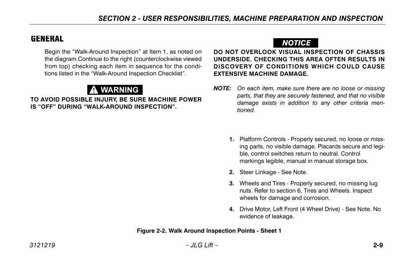
GENERALBegin the “Walk-Around Inspection” at Item 1, as noted onthe diagram.Continue to the right (counterclockwise viewedfrom top) checking each item in sequence for the condi-tions listed in the “Walk-Around Inspection Checklist”.
TO AVOID POSSIBLE INJURY, BE SURE MACHINE POWERIS “OFF” DURING “WALK-AROUND INSPECTION”.
DO NOT OVERLOOK VISUAL INSPECTION OF CHASSISUNDERSIDE. CHECKING THIS AREA OFTEN RESULTS INDISCOVERY OF CONDITIONS WHICH COULD CAUSEEXTENSIVE MACHINE DAMAGE.
NOTE: On each item, make sure there are no loose or missingparts, that they are securely fastened, and that no visibledamage exists in addition to any other criteria men-tioned.
1. Platform Controls - Properly secured, no loose or miss-ing parts, no visible damage. Placards secure and legi-ble, control switches return to neutral. Control markings legible, manual in manual storage box.
2. Steer Linkage - See Note.
3. Wheels and Tires - Properly secured, no missing lug nuts. Refer to section 6, Tires and Wheels. Inspect wheels for damage and corrosion.
4. Drive Motor, Left Front (4 Wheel Drive) - See Note. No evidence of leakage.
Figure 2-2. Walk Around Inspection Points - Sheet 1
3121219 – JLG Lift – 2-9

SECTION 2 - USER RESPONSIBILITIES, MACHINE PREPARATION AND INSPECTION
9. Fuel Tank (Gasoline or Diesel Engine) - Filler cap secure, sight gauge visible, no damage or leaks.
10. Ground Controls - Switches operable, no visible dam-age, placards secure and legible.
11. Control Valve - See Note.
12. Drive Motor, Left Rear - See Note.
13. Drive Brake, Left Rear - No loose or missing parts, no visible damage, no evidence of leakage.
14. Manual Descent Cable and Pull Handle - See Note.
15. Ladder - No damage, securely attached.
16. Speed Cutout Switch - No visible damage, properly secured.
17. Battery Installation (Gasoline or Diesel Engine) - Proper electrolyte level, cables secure, no damage or corrosion. Hold-downs secure.
18. Hydraulic Pump - Pump properly secured, no visible damage, no evidence of leakage. Hoses and fittings properly secured, no visible damage, no evidence of leaks.
19. Engine Installation - Engine oil to full mark on dipstick, oil filler cap secure. Muffler/exhaust system properly secured, no leakage. Air filter assembly secure, no loose or missing parts, element clean. Radiator cap secure, coolant to correct level.
20. Steer Cylinder and Tie Rod Ends - No loose or missing parts, no visible damage. No steer cylinder leaks or damage.
21. Platform Assembly - See Note. Platform deck exten-sion operates properly
Figure 2-3. Walk Around Inspection Points - Sheet 2
2-10 – JLG Lift – 3121219

SECTION 3 - USER RESPONSIBILITIES AND MACHINE CONTROL
SECTION 3. USER RESPONSIBILITIES AND MACHINE CONTROL
3.1 GENERAL
THE MANUFACTURER HAS NO DIRECT CONTROL OVERMACHINE APPLICATION AND OPERATION, CONFOR-MANCE WITH GOOD SAFETY PRACTICES IN THESE AREASIS THE RESPONSIBILITY OF THE USER AND HIS OPERAT-ING PERSONNEL.
This section provides the necessary information needed tounderstand control functions. Included in this section are theoperating characteristics and limitations, and functions andpurposes of controls and indicators. It is important that theuser read and understand the proper procedures beforeoperating the machine. These procedures will aid in obtain-ing optimum service life and safe operation.
3.2 OPERATING CHARACTERISTICS AND LIMITATIONS
GeneralA thorough knowledge of the operating characteristics andlimitations of the machine is always the first requirement forany user, regardless of user’s experience with similar typesof equipment.
PlacardsImportant points to remember during operation are providedat the control stations by DANGER, WARNING, CAUTION,IMPORTANT and INSTRUCTION placards. This informationis placed at various locations for the express purpose ofalerting personnel of potential hazards constituted by theoperating characteristics and load limitations of the machine.See foreword for definitions of the above placards.
CapacitiesRaising platform above horizontal with or without any load inplatform, is based on the following criteria:
1. Machine is positioned on a smooth, firm and level sur-face.
2. Load is within manufacturer’s rated capacity.
3. All machine systems are functioning properly.
3121219 – JLG Lift – 3-1

SECTION 3 - USER RESPONSIBILITIES AND MACHINE CONTROL
3.3 CONTROLS AND INDICATORS(Refer to Figure 3-1.)
The machine is equipped with control panels that use sym-bols instead of words to indicate control functions.
Ground Control Station
DO NOT OPERATE FROM GROUND CONTROL STATIONWITH PERSONNEL IN THE PLATFORM EXCEPT IN ANEMERGENCY.
PERFORM AS MANY PRE-OPERATIONAL CHECKS ANDINSPECTIONS FROM THE GROUND CONTROL STATION ASPOSSIBLE.
NOTE: When the machine is shut down for overnight parking orbattery charging, the EMERGENCY STOP and POWERSELECTOR switches must be positioned to OFF to pre-vent draining the batteries.
1. Power Selector Switch - A three position, key-operated power selector switch supplies operating power to the platform or ground controls, as selected. When posi-tioned to platform, the switch provides power to the emergency stop switch at the platform controls. When
positioned to ground, the switch provides power to the emergency stop switch at the ground controls. With the power selector switch in the center off position, power is shut off to both platform and ground controls and the key can be removed to disable the machine.
NOTE: With the Power Selector switch in the off position, the keycan be removed in order to incapacitate the machine onthe jobsite to avoid unauthorized use of the machine.
With the POWER SELECTOR switch positioned toGROUND, ground functions will operate at low speed atall times.
NOTE: Low speed is the default speed for all functions. When theplatform is elevated, all functions operate in creep speedonly.
2. Latch - Allows box to be opened and closed.
3. Circuit Breaker - This 10 Amp circuit breaker, located on the left side of the platform control box, restores inter-rupted power to the platform controls.
4. Alternator LED - Illuminates when the alternator drops below a pre-set level.
5. Oil Pressure LED - Illuminates when the engine oil pres-sure drops below 7 psi (0.48 bar).
3-2 – JLG Lift – 3121219

SECTION 3 - USER RESPONSIBILITIES AND MACHINE CONTROL
6. Glow Plug Switch - A momentary contact, push button type switch that supplies electrical power to the engine’s glow plugs, when depressed, to assist cold starting.
7. Water Temperature LED - Illuminates when engine water temperature becomes overheated.
8. Charge Pressure - Illuminates when the charge pressure drops below 70 psi (4.8 bar), indicating the charge filter is clogged and needs to be replaced. The indicator is also connected to a temperature sensor to prevent false signals from being generated when the hydraulic oil is below normal operating temperature.
9. Lift Switch - A three position, momentary contact Lift control switch provides raising and lowering of the plat-form when positioned to up or down.
10. Hourmeter -The machine may be equipped with an hourmeter to indicate the number of hours the machine has been operated.
11. Ignition/Emergency Stop Switch - A two-position, red, mushroom-shaped ignition/emergency stop switch, when positioned to ON with the power selector switch positioned to ground, furnishes operating power to the ground control station. In addition, the switch can be used to turn off power to the function controls in the event of an emergency. Power is turned on by pulling
the switch out (on), and is turned off by pushing the switch in (off).
12. Start Switch - A momentary contact, push button type switch that supplies electrical power to the starter sole-noid when the emergency stop switch is in the ON posi-tion and the start button is depressed.
13. Platform Overload LED (If Equipped) - Indicates the plat-form has been overloaded. An audible alarm will also signal when the platform is overloaded.
NOTE: If the Overload Indicator is illuminated, all functions will beprevented from the platform controls. Using the groundcontrols or manual descent, fully lower the machine andreduce the weight in the platform so as to not exceed therated workload indicated on the capacity decal.
3121219 – JLG Lift – 3-3

SECTION 3 - USER RESPONSIBILITIES AND MACHINE CONTROL
.
1705729 B
1 2 34
5
6
7
8
910
11
12
13
Figure 3-1. Ground - Control Station
1. Platform/Ground Select Switch
2. Latch
3. Circuit Breaker
4. Alternator LED
5. Oil Pressure LED
6. Glow Plug Switch
7. Water Temperature LED
8. Hydraulic Charge Pressure LED
9. Lift Switch
10. Hourmeter
11. Emergency Stop Switch
12. Start Switch
13. Platform Overload LED (does not apply to all machines)
3-4 – JLG Lift – 3121219

SECTION 3 - USER RESPONSIBILITIES AND MACHINE CONTROL
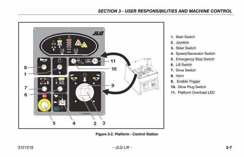
3.4 PLATFORM CONTROL STATION(Refer to Figure 3-2.)
1. Start Switch - A momentary contact, push button type switch that supplies electrical power to the starter sole-noid when the emergency stop switch is in the on posi-tion and the start button is depressed.
2. Controller (Joystick) - The Joystick controls three func-tions: drive, lift, and drive/lift speed. The drive or the lift function switch must be selected prior to moving the machine with the Joystick. The speed is controlled by the travel distance of the Joystick.
3. Steer Switch - The thumb-operated steer switch on top of the Joystick handle activates the steer wheels in the direction it is moved (right or left).
4. Speed/Generator Switch - The three position speed/generator switch permits the operator to select either high range, low range or the generator (if equipped).
NOTE: The machine cannot be lifted up from platform controls ordriven when the generator is selected.
4 wheel drive is operational in low drive only.
DO NOT USE HIGH ENGINE SPEED WHEN DRIVING INCLOSE QUARTERS OR WHEN DRIVING IN REVERSE.
NOTE: If machine is being operated in high range speed and theplatform is raised above 90-96 in. (2.3-2.4m), the enginespeed switch will cut-out returning drive speed to lowuntil the platform is again lowered below the cut-out level.
5. Emergency Stop Switch - A two-position, red, mush-room-shaped emergency stop switch functions to pro-vide power to the platform control station and also to turn off power to the platform function controls in the event of an emergency. With the Power selector switch positioned to platform, power is turned on by pulling the switch out (on), and is turned off by pushing the switch in (off).
DO NOT “LIFT DOWN” WITHOUT COMPLETELY RETRACT-ING THE PLATFORM EXTENSION.
6. Lift Select Switch - The lift switch provides for raising and lowering the platform. Lift is activated by pressing the enable switch and positioning the joystick forward or backward.
3121219 – JLG Lift – 3-5

SECTION 3 - USER RESPONSIBILITIES AND MACHINE CONTROL
7. Drive Select Switch - The drive switch provides for driv-ing the lift. Drive is activated by selecting the drive switch and positioning the joystick forward or back-ward.
8. Horn - (If Equipped) - This push-button switch, when activated, permits the operator to warn jobsite person-nel when the machine is operating in the area.
9. Enable Trigger - Trigger on the front of the joystick must be held in to perform joystick controlled movements.
10. Glow Plug Switch - Glow Plug Switch - A momentary contact, push button type switch that supplies electrical power to the engine’s glow plugs, when depressed, to assist cold starting.
11. Platform Overload LED (does not apply to all machines) - Illuminates when platform becomes overloaded. When LED illuminates, immediately remove excess weight from platform to continue safe operation.
3-6 – JLG Lift – 3121219
SECTION 3 - USER RESPONSIBILITIES AND MACHINE CONTROL
1706763 A
1705976B
8
1
7
6
5 4 32
10
11
9
Figure 3-2. Platform - Control Station
1. Start Switch
2. Joystick
3. Steer Switch
4. Speed/Generator Switch
5. Emergency Stop Switch
6. Lift Switch
7. Drive Switch
8. Horn
9. Enable Trigger
10. Glow Plug Switch
11. Platform Overload LED
3121219 – JLG Lift – 3-7

SECTION 3 - USER RESPONSIBILITIES AND MACHINE CONTROL
Platform Control Front Panel(Refer to Figure 3-3.)
1. Fuel/Glow Plug Selector Switch - Selects which fuel source will be used. LPG vs. Gasoline or Diesel for die-sel machines.
2. Auto Leveling Jacks - The leveling jacks switch is located on the front of the platform control box. When depressed, the outrigger light will illuminate on the indi-cator pad. Moving the control handle forward will lower the leveling jacks. Moving the control handle backward will raise the leveling jacks. Once the machine is level, the jacks will discontinue extending and the jack set light will illuminate.
NOTE: After initial ground contact is made, the auto level functionwill pause 2-5 seconds and then begin to properly levelthe machine to the specified market specification. Oncelevel, the tilt light on the platform control box will stopblinking.
NOTE: There is an override feature on the Auto Leveling systemthat allows the operator to adjust (trim) the level of themachine to the left or right when the platform is com-pletely lowered. Use the following instructions to adjustthe level of the machine.
a. Select the leveling jack selection switch andsqueeze the red trigger switch on the controller.
b. To adjust the leveling jacks to the left, activate theswitch on top of the controller to the left. To adjustto the right, activate the switch on top of the control-ler to the right. The leveling jack indicator light forthe side selected will be lit.
3-8 – JLG Lift – 3121219

SECTION 3 - USER RESPONSIBILITIES AND MACHINE CONTROL
Figure 3-3. Platform - Control Front Panel
1. Dual Fuel Selector Switch
2. Diesel Fuel Selector Switch
3. Outrigger Switch
3121219 – JLG Lift – 3-9

SECTION 3 - USER RESPONSIBILITIES AND MACHINE CONTROL
Indicator Panel LED’s(Refer to Figure 3-4.)
1. Drive - This LED will illuminate when the drive select but-ton is activated.
2. Lift - This LED will illuminate when the lift select button is activated.
3. Fuel Gauge - This series of LED’s give the operator a visual of the amount of fuel remaining.
4. Tilt Alarm Warning Light - This red warning light on the control panel will illuminate when the chassis is on a severe slope.
5. Engine/Filter Distress Light - This warning light, when illuminated, warns the operator of an engine or hydraulic system fault condition. A bank of warning lights, located at the ground control station, indicates the specific fault condition to the operator. The indicator lights are: Alter-nator, Charge Pressure, Engine Temperature, Oil Pres-sure, and Return Filter.
6. Leveling Jacks (retracted) - This set of lights will illumi-nate once all the leveling jacks are retracted.
7. Leveling Jacks (extended) - This set of lights will illumi-nate once all the leveling jacks are extended.
FOR MACHINES EQUIPPED WITH THE YANMAR DIESELENGINE, THE TIMER RELAY MUST SEAT THE FUEL SOLE-NOID WITH ITS INITIAL PULSE, OR THE ENGINE WILL NOTSTART. PROLONGED NO-START IS AN INDICATION THATTHE FUEL SOLENOID HAS NOT SEATED OR THAT THEREIS NO FUEL. IF THE ENGINE FAILS TO START, THE STARTSWITCH MUST BE RE-CYCLED TO PULSE THE FUEL SOLE-NOID INTO THE SEATED POSITION.
IF TILT ALARM IS ON WHEN PLATFORM IS RAISED, LOWERPLATFORM COMPLETELY, THEN REPOSITION MACHINESO THAT IT IS LEVEL BEFORE RAISING PLATFORM.
DO NOT OPERATE MACHINE IF HIGH DRIVE SPEED OPER-ATES WHEN PLATFORM IS RAISED ABOVE THE STOWEDPOSITION.
3-10 – JLG Lift – 3121219

SECTION 3 - USER RESPONSIBILITIES AND MACHINE CONTROL
1. Drive
2. Lift
3. Fuel Gauge
4. Tilt
5. Engine Distress
6. Leveling Jacks (Retracted)
7. Leveling Jacks (Set)
Figure 3-4. Platform - Indicator Panel
3252695B
12 3 4
5
67
3121219 – JLG Lift – 3-11

SECTION 3 - USER RESPONSIBILITIES AND MACHINE CONTROL
22 24 26
15
1214
8
106
13
30
31
26
20
9
224
5
1516
719
21 23102
26
11
101
105
104
107
106
23
4
1214
524
105
2622
107
25329
103
Figure 3-5. Decal Location (ANSI)
3-12 – JLG Lift – 3121219

SECTION 3 - USER RESPONSIBILITIES AND MACHINE CONTROL
Table 3-1. Decal Legend (ANSI)
Item # 0259792-8
1-3 --4 17021535 17026316 --7 17038168 17041389 170452910 --11
Prior to S/N 102883S/N 102883 to Present
17037881701509
12 170150013 170381214 170381415 170427716 1703819
17-18 --19 170448020 170455621 170369622 1703818
23 170382124 325181325 --26 3252689
27-29 --30 170441231 100113127032 --
101(Optional)
1702788
102Dual Fuel
Diesel17029611702962
103Dual Fuel
Diesel17015421701505
104(Dual Fuel Only)
1700818
105 1701214106 1702773107 1704885
Table 3-1. Decal Legend (ANSI)
Item # 0259792-8
3121219 – JLG Lift – 3-13

SECTION 3 - USER RESPONSIBILITIES AND MACHINE CONTROL
22 24 26
15
1214
8
106
13
30
31
26
20
9
224
5
1516
719
21 23102
26
11
101
105
104
107
106
23
4
1214
524
105
2622
107
25329
103
33
Figure 3-6. Decal Location (ANSI Export)
3-14 – JLG Lift – 3121219

SECTION 3 - USER RESPONSIBILITIES AND MACHINE CONTROL
Table 3-2. Decal Legend (ANSI Export)
Item #Brazil
0259795-7CSA
0272257-3
Latin American0259794-7
1-3 -- -- --4 1704008 1704006 17040075 1702631 1702631 17026316 -- -- --7 1704699 1704684 17046918 1704138 1704138 17041389 1704529 1704529 170452910 -- -- --11
Prior to S/N 102883S/N 102883 to Present
17037881701509
17037881701509
17037881701509
12 1703811 1703811 170381113 1703812 1703812 170381214 1703814 1703814 170381415 1704277 1704277 170427716 1703819 1703819 1703819
17-18 -- -- --19 1704700 1704685 170469220 1704623 1704688 170469521 1704748 1704597 170459822 1704701 1704686 170469323 1704702 1704687 170469424 3251813 3251813 3251813
25 -- -- --26 3252689 3252689 3252689
27-29 -- -- --30 1704412 1704412 170441231 -- 1001131270 --32 -- -- --33 -- 1705303 --101
(Optional)1702788 1702788 1702788
102Dual Fuel
Diesel17029611702962
17029611702962
17029611702962
103Dual Fuel
Diesel17015421701505
17015421701505
17015421701505
104(Dual Fuel Only)
EnglishEnglish/Spanish LanguageEnglish/French Language
170081817027201704271
170081817027201704271
170081817027201704271
105 1704698 1704690 1704697106 1702773 1702773 1702773107 1704885 1704885 1704885
Table 3-2. Decal Legend (ANSI Export)
Item #Brazil
0259795-7CSA
0272257-3
Latin American0259794-7
3121219 – JLG Lift – 3-15

SECTION 3 - USER RESPONSIBILITIES AND MACHINE CONTROL
22 24 26
15
1214
8
17104
13
30
26
20
31
9
1722
5
1516
7
26
11
101
103
105
104
23
1214
524
103
2622
105
2532
9
102
Figure 3-7. Decal Location (CE/AUS)
3-16 – JLG Lift – 3121219

SECTION 3 - USER RESPONSIBILITIES AND MACHINE CONTROL
Table 3-3. Decal Legend - (CE/AUS)
Item #CE/AUS
0275087-2
1-4 --
5 1702631
6 --
7 1704548
8 1704138
9 1704529
10 --
11Prior to S/N 102883
S/N 102883 to Present17037881701509
12 1703811
13 1703812
14 1703814
15 1704277
16 1703819
17 1705084
18-19 --
20 1706332
21 --
22 1706338
23 --
24 3251813
253252533 (CE)
3252534 (AUS)
26 1705671
27-29 --
30 1704412
31 --
101(Optional)
1702788
102 1701505
103 1701785
104 1702773
105 1704885
Table 3-3. Decal Legend - (CE/AUS)
Item #CE/AUS
0275087-2
3121219 – JLG Lift – 3-17

SECTION 3 - USER RESPONSIBILITIES AND MACHINE CONTROL
This page left blank intentionally.
3-18 – JLG Lift – 3121219

SECTION 4 - MACHINE OPERATION
SECTION 4. MACHINE OPERATION
4.1 DESCRIPTIONThis machine is a self-propelled hydraulic lift equipped with awork platform on an elevating scissor mechanism. Vibrationsemitted by these machines are not hazardous to an operatorin the work platform. The equivalent continuous A-Weightedsound pressure level at the work platform is less than 70dB(A).
The primary operator control station is in the platform. Fromthis control station, the operator can drive and steer themachine in both forward and reverse directions. Themachine has a Ground Control Station which will overridethe Platform Control Station. Ground Controls operate liftand lower and are to be used in an emergency to lower theplatform to the ground should the operator in the platform beunable to do so. Ground Control is also to be used in Pre-Start Inspection.
4.2 ENGINE OPERATION
Power Selector Switch
The power selector switch functions to direct electrical powerto the desired control station. With the switch in the groundposition, power is supplied to the emergency stop switch atthe ground control station. When the switch is in the platformposition, power is supplied to the emergency stop switch atthe platform control station. The switch should be in the offposition when parking the machine overnight.
Emergency Stop Switch
This switch, when in the on (out) position, provides electricalpower to the ground controls or platform controls, as appli-cable. In addition, the switch can be used to turn off power(push the switch IN) to the function controls in the event ofan emergency.
Starting Procedure
NOTE: Initial starting should always be performed from theGround Control Station.
3121219 – JLG Lift – 4-1

SECTION 4 - MACHINE OPERATION
1. Check engine oil before attempting to start engine; ifnecessary, add oil in accordance with Engine Manufac-turers Manual.
2. Pull out the red EMERGENCY STOP switch (ON).
3. Position the PLATFORM/GROUND SELECT switch tothe desired operating control station (PLATFORM orGROUND).
4. If operating a dual fuel machine, place the LPG/GASO-LINE SELECT switch to the desired position.
NOTE: If the LPG system is selected, ensure that the hand valveon the LPG supply tank is opened prior to attempting tostart the engine.
IF ENGINE FAILS TO START PROMPTLY, DO NOT CRANKFOR AN EXTENDED PERIOD. SHOULD ENGINE FAIL TOSTART ONCE AGAIN, ALLOW STARTER TO “COOL OFF”FOR 2 TO 3 MINUTES. IF ENGINE FAILS TO START AFTERSEVERAL ATTEMPTS, REFER TO ENGINE MAINTENANCEMANUAL.
IF STARTING MACHINE FROM THE PLATFORM CONTROLSTATION, PLACE THE ENGINE SPEED CONTROL TO THELOW POSITION PRIOR TO STARTING THE ENGINE.
5. If starting the machine from the ground controls, posi-tion the EMERGENCY STOP switch to ON and depressthe START button and hold until until the engine starts. Ifstarting from the platform controls, position the platformEMERGENCY STOP switch to ON and depress theSTART button and hold until the engine starts.
ALLOW ENGINE TO WARM-UP FOR A FEW MINUTESBEFORE APPLYING ANY LOAD.
6. After the engine has had sufficient time to warm up, pro-ceed with operation of the unit.
4-2 – JLG Lift – 3121219

SECTION 4 - MACHINE OPERATION
4.3 OPERATING CHARACTERISTICS
Leveling Jacks
The machine may be equipped with auto leveling jacks witha manual adjust feature. These leveling jacks are operatedthrough one switch unlike the traditional four switch system.The leveling jacks are operated by a bang bang valve.
NOTE: The engine speed will drop when the leveling jacks areactivated.
Auto Leveling
1. With the machine in the stowed position turn the poweron, start machine and depress the leveling jack selec-tion switch located on the front of the platform controlbox.
2. While squeezing the red trigger switch on the controller,move the controller forward.
3. Once the leveling jacks make contact with the groundsurface there will be up to a 5 second delay before theactual auto leveling begins.
NOTE: Due to varying ground conditions, there may be severaldelays between machine level corrections. Be sure ample
time is allowed for all leveling adjustments to be com-pleted.
4. Continue to engage the leveling jacks until the tilt lightstops blinking and is no longer lit.
NOTE: If you receive a 2/5 flash code through the system faultlight at the platform control station the machine is unableto level. You must reposition and try again.
5. To retract the leveling jacks, move the controller back-ward until the desired position is obtained.
NOTE: The tilt light serves as an indicator that the machine is out-side the allowable lifting operation. When the machinereaches a position within level of the specific marketspecification, the tilt light will go out. Once the light is out,the level adjustment of the machine may still be improved.(See Manual Level Adjustment (Trim) section).
NOTE: There is a limit switch that senses when all four cylindersare fully retracted and this will light up the four levelingjack lights in the platform control station.
The proximity sensor will not allow the jacks to beextended or retracted when the machine is elevated. Ifthere is a proximity sensor failure you cannot use the lev-eling jacks.
3121219 – JLG Lift – 4-3

SECTION 4 - MACHINE OPERATION
Manual Level Adjustment (Trim)
NOTE: There is an override feature on the Leveling Jack systemthat allows the operator to adjust (trim) the level of themachine to the left or right when the platform is com-pletely lowered. Use the following instructions to adjustthe level of the machine.
6. With the machine in the stowed position turn the poweron, start machine and depress the leveling jack selec-tion switch located on the front of the platform controlbox.
7. To adjust (trim) the machine to the right, activate thesteer switch on the top of the controller to the right untilthe desired position is reached.
8. To adjust (trim) the machine to the left, activate the steerswitch on the top of the controller to the left until thedesired position is reached.
NOTE: Anytime the trim function is used there is a possibility thatthe machine may become out of level. At this time themachine will no longer lift but the machine can be low-ered.
NOTE: The machine must be in the stowed position before thetrim function is operable.
4.4 PLATFORM
Platform Loading
The platform maximum rated load capacity is shown on aplacard located on the platform and is based upon the fol-lowing criteria:
1. The machine is positioned on a smooth, firm and levelsurface.
2. All braking devices are engaged.
3. The maximum platform capacity in its standard configu-ration is 1,250 lb. (570 kg). See note.
4. The maximum capacity of the manual platform exten-sion is 300lb. (140 kg).
NOTE: It is important to remember that the load should be evenlydistributed on the platform. The load should be placednear the center of the platform when possible.
4-4 – JLG Lift – 3121219

SECTION 4 - MACHINE OPERATION
Raising
DO NOT RAISE PLATFORM EXCEPT ON A SMOOTH, FIRM,AND LEVEL SURFACE, FREE OF OBSTRUCTIONS ANDHOLES.
1. If the machine is shut down, place the power selectorswitch to desired position (platform or ground).
2. Position the applicable emergency stop Switch to the onposition.
3. If operating from the ground controls, position the liftswitch to up and hold until desired elevation is achieved.If operating from the platform controls, press the enableswitch then position the lift switch to up and hold untildesired elevation is reached. The lift switch is part of theenable circuit, which supplies power to the lift switch for3 seconds after the enable switch is pressed. If the liftswitch is not activated within 3 seconds after the enableswitch is pressed, power is removed from the circuit andthe enable switch must be pressed again before activat-ing the lift switch.
Lowering
ENSURE SCISSOR ARM AREA IS FREE OF PERSONNELPRIOR TO LOWERING PLATFORM.
ENSURE PLATFORM EXTENSION IS COMPLETELYRETRACTED PRIOR TO LOWERING PLATFORM.
If operating from the ground controls, position the lift switchto down and hold until desired elevation is achieved or untilplatform is fully lowered.
If operating from the platform controls, press the lift switchand then position the joystick to down and hold until desiredelevation is reached or until platform is fully lowered.
DO NOT ‘LIFT DOWN’ WITHOUT COMPLETELY RETRACT-ING THE PLATFORM EXTENSION.
3121219 – JLG Lift – 4-5

SECTION 4 - MACHINE OPERATION
Platform Extension
The machine is equipped with a mechanically extendabledeck, which adds 3 ft (0.9 m) to the front of the platform, giv-ing the operator better access to work-sites.
To extend the deck, squeeze the release lever on the handleon the left side of the platform to release the lock pin, thenuse the handle and handrail to push the extendable deckout.To retract the deck, squeeze the release lever to release thelock pin and use the handle and handrail to pull and retractthe deck.Be sure the lock pin is locked in place after the deck isretracted.
Maximum capacity of the deck extension is 300 lbs (136 kg).
DO NOT ‘LIFT DOWN’ WITHOUT COMPLETELY RETRACT-ING THE PLATFORM EXTENSION.
4.5 DRIVING
DO NOT DRIVE WITH PLATFORM RAISED EXCEPT ON ASMOOTH, FIRM AND LEVEL SURFACE FREE OF OBSTRUC-TIONS AND HOLES.
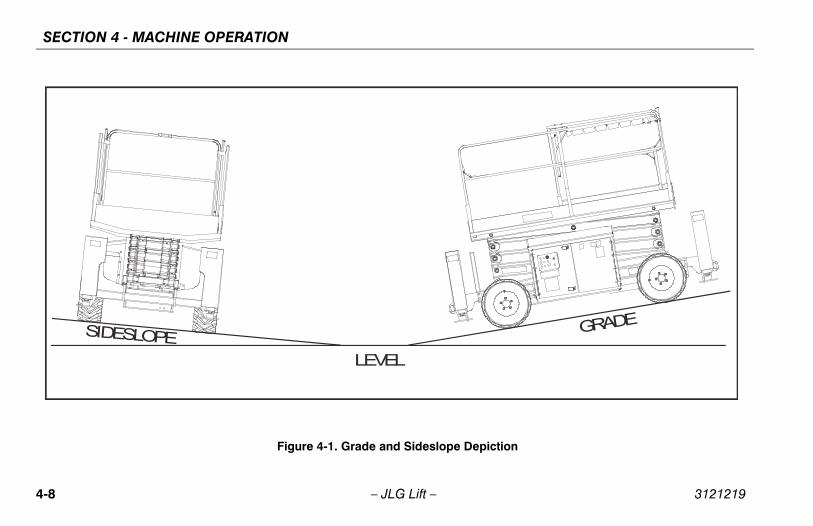
TO AVOID LOSS OF TRAVEL CONTROL OR UPSET ONGRADES AND SIDESLOPES, DO NOT DRIVE MACHINE ONGRADES EXCEEDING THOSE SPECIFIED ON CAUTIONPLACARD AT PLATFORM.
TRAVEL GRADES IN “LOW” DRIVE SPEED ONLY. USEEXTREME CAUTION WHEN DRIVING IN REVERSE AND ATALL TIMES WHEN DRIVING WITH PLATFORM ELEVATEDAND ESPECIALLY WHEN DRIVING WITH ANY PART OFMACHINE WITHIN 6 FEET (1.8 M) OF AN OBSTRUCTION.
Steering
To steer the machine, the thumb operated steer controlswitch on the controller handle is positioned to the right fortraveling right, or to the left for traveling left. When released,the switch will return to the center-off position and the wheelswill remain in the previously selected position. To return the
4-6 – JLG Lift – 3121219

SECTION 4 - MACHINE OPERATION
wheels to the straightened position, the switch must be acti-vated in the opposite direction until the wheels are centered.
Driving Forward
1. Place the power selector switch at the ground controlstation to platform.
2. Position the emergency stop switch at the platform con-trol station to the on position.
3. Press the drive switch and move the joystick forwardand hold for the duration of travel.Drive speed is determined by the distance the controlhandle is moved from the center off position.For additional drive speed, position the high enginespeed switch to high while operating in the drive forwardmode.
Driving in Reverse
1. Position the power selector switch at the ground controlstation to platform.
2. Position the emergency stop switch at the platform con-trol station to the on position.
3. Press the drive switch and move the drive controllerrearward and hold for the duration of travel.Drive speed is determined by the distance the control
handle is moved from the center off position.Do not activate the high engine speed switch when trav-eling in reverse.
3121219 – JLG Lift – 4-7
SECTION 4 - MACHINE OPERATION
LEVEL
SIDESLOPEGRADE
Figure 4-1. Grade and Sideslope Depiction
4-8 – JLG Lift – 3121219

SECTION 4 - MACHINE OPERATION
4.6 PARKING AND STOWINGPark and stow the machine as follows:
1. Drive the machine to a reasonably well-protected andwell-ventilated area.
2. Ensure the platform is fully lowered.
3. Position the emergency stop switch to the off position.
4. If necessary, cover the instruction placards, caution andwarning decals so that they will be protected from hos-tile environment.
5. Chock at least two wheels when parking the machine foran extended period of time.
6. Turn the power selector switch to off and remove the keyto disable the machine from unauthorized use.
4.7 TIE DOWNWhen transporting the machine, the platform extension mustbe fully retracted and the platform fully lowered in the stowedmode with the machine securely tied down to the truck ortrailer deck. Four tie down eyes, one at each corner of themachine frame, are provided for machine tie-down.
Lifting
If it becomes necessary to lift the machine, it is possible to do sofrom the tie down/lift lugs. These lugs enable the machine to belifted using cranes or other suitable lifting devices.
NOTE: If lifting becomes necessary from the lifting lugs, JlgIndustries Inc. recommends the use of a proper spreaderbar to avoid damage to the machine.
Cranes or other lifting devices must be capable of han-dling 7660 lb (3475 kg)
3121219 – JLG Lift – 4-9

SECTION 4 - MACHINE OPERATION
4.8 TOWINGAlthough towing the machine is prohibited, provisions formoving the machine, in case of a malfunction or power fail-ure, have been incorporated. The following procedures areto be used ONLY for emergency movement to a suitablemaintenance area.
1. Chock the wheels securely.
2. Locate the brake cartridge on the hydraulic control valve, located adjacent to the hydraulic oil tank on the left side of the machine. Depress the plunger on the brake cartridge.
3. Locate the brake release pump, in front of the hydraulic control valve. Install the handle on the brake release pump and pump it to release the brake. Remove handle when finished.
4. Using suitable equipment for assistance, remove the chocks, winch or tow the machine to an appropriate maintenance area.
USE EXTREME CAUTION WHEN OPENING THE TOWVALVE. THE DRIVE FUNCTION WILL STILL OPERATE WITHTHE TOW VALVE OPEN, BUT THE BRAKE IS DISABLED.ENSURE THE TOW VALVE REMAINS CLOSED AT ALL
TIMES, EXCEPT WHEN THE MACHINE IS BEING TOWED.CLOSE THE TOW VALVE IMMEDIATELY AFTER TOWING ISCOMPLETED.
After moving the machine, complete the following proce-dures:
1. Position the machine on a firm, level surface.
2. Chock the wheels securely.
3. Turn knob counterclockwise to engage wheel brakes.
4. Turn the knob on the brake pump clockwise until tight. this places the machine back into normal operation
5. Remove the chocks from the wheels.
4-10 – JLG Lift – 3121219

SECTION 4 - MACHINE OPERATION
MODEL
260MRT 78 41.5 28.5
WHEELBASE(in)
X(in)
Z(in)
X Z
Figure 4-2. Lifting Chart
3121219 – JLG Lift – 4-11

SECTION 4 - MACHINE OPERATION
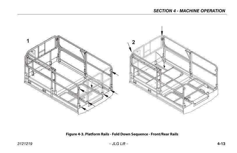
4.9 PLATFORM RAILS - FOLD-DOWN PROCEDURE
DO NOT RAISE PLATFORM WITH RAILS FOLDED DOWN.THE RAILS MUST BE IN THE UPRIGHT POSITION ANDPROPERLY PINNED WHEN RAISING THE PLATFORM.
NOTE: The rails must only be folded down when the machine isin the stowed (platform fully lowered) position.The platform control box should be removed from mountbefore the side rails are folded down.
The platform rails fold down in the following sequence;(See Figure 4-3., Figure 4-4. and Figure 4-5.)
• Rear Gate Rail (6 Pins)
• Front Rail (2 Pins)
• Left Extension Deck Rail (1 Pin)
• Right Extension Deck Rail (1 Pin)
• Left Platform Side Rail (3 Pins)
• Right Platform Side Rail (3 Pins)
1. To fold down each of the rails, remove the bail pins forthat rail.
2. Taking a firm hold on the top rail, carefully lower until thetop rail is fully folded in the down position.
AFTER THE RAILS HAVE BEEN FOLDED DOWN, USEEXTREME CAUTION WHEN EXITING AND ENTERING THEPLATFORM. ENTER AND EXIT PLATFORM ONLY AT THEGATE AREA AND LADDER PROVIDED.
IF OPERATING (DRIVING) MACHINE WITH PLATFORMCONTROL STATION FROM GROUND, WITH RAILS FOLDED,KEEP AT LEAST 3 FT. (1 M) DISTANCE FROM MACHINE.
3. To raise the rails back to the upright position, unfold therails in the reverse sequence they were folded. Firmlypull the rails back up into position and replace the bailpins into the rails.
4-12 – JLG Lift – 3121219
SECTION 4 - MACHINE OPERATION
Figure 4-3. Platform Rails - Fold Down Sequence - Front/Rear Rails
3121219 – JLG Lift – 4-13

SECTION 4 - MACHINE OPERATION
Figure 4-4. Platform Rails - Fold Down Sequence - Deck Extension Side Rails
4-14 – JLG Lift – 3121219

SECTION 4 - MACHINE OPERATION
Figure 4-5. Platform Rails - Fold Down Sequence - Main Platform Side Rails
3121219 – JLG Lift – 4-15

SECTION 4 - MACHINE OPERATION
This page left blank intentionally.
4-16 – JLG Lift – 3121219

SECTION 5 - EMERGENCY PROCEDURES
SECTION 5. EMERGENCY PROCEDURES
5.1 GENERALThis section provides information on the procedures to befollowed and on the systems and controls to be used in theevent an emergency situation is encountered duringmachine operation. Prior to operation of the machine andperiodically thereafter, the entire operating manual, includingthis section, should be reviewed by all personnel whoseresponsibilities include any work or contact with themachine.
Emergency Stop SwitchThese large red buttons, one located at the Ground ControlStation and one at the Platform Control Station, will immedi-ately stop the machine when depressed.
CHECK MACHINE DAILY TO MAKE SURE EMERGENCYSTOP BUTTON IS IN PLACE AND THAT GROUND CONTROLINSTRUCTIONS ARE IN PLACE AND LEGIBLE.GROUNDCONTROL STATION
The Ground Control Station is located on the left side of themachine frame. The controls on this panel provide the
means for overriding the platform controls and for controllingthe platform lift up and down functions from the ground.Place the power select switch in the ground position andoperate the lift switch to lift up or down.
Manual DescentThe manual descent valve is used, in the event of total powerfailure, to lower the platform using gravity. The manualdescent ring is located on the front of the machine frame,between the scissor arms. The ring is connected, by a cable,to the manual descent valve on the lift cylinder. Pulling themanual descent ring opens the valve spool, lowering theplatform.
5.2 EMERGENCY OPERATIONUse of Ground Controls
KNOW HOW TO USE THE GROUND CONTROLS IN ANEMERGENCY SITUATION.
Ground personnel must be thoroughly familiar with themachine operating characteristics and the ground controlfunctions. Training should include operation of the machine,
3121219 – JLG Lift – 5-1

SECTION 5 - EMERGENCY PROCEDURES
review and understanding of this section and hands-on oper-ation of the controls in simulated emergencies.
Operator Unable to Control Machine1. Operate the machine from ground controls ONLY with
the assistance of other personnel and equipment (cranes, overhead hoists, etc.) as may be required to safely remove the danger or emergency condition.
2. Other qualified personnel on the platform may use the platform controls. DO NOT CONTINUE OPERATION IF CONTROLS DO NOT FUNCTION NORMALLY.
3. Cranes, forklift trucks or other equipment which may be available are to be used to remove platform occupants and stabilize motion of the machine in case machine controls are inadequate or malfunction when used.
Platform Caught OverheadIf the platform becomes jammed or snagged in overheadstructures or equipment, do not continue operation of themachine from either the platform or the ground until theoperator and all personnel are safely moved to a securelocation. Only then should an attempt be made to free theplatform using any necessary equipment and personnel. Donot operate controls to cause one or more wheels to leavethe ground.
Righting of Tipped MachineA forktruck of suitable capacity or equivalent equipmentshould be placed under the elevated side of the chassis, witha crane or other suitable lifting equipment used to lift theplatform while the chassis is lowered by the forklift or otherequipment.
Post-Incident InspectionFollowing any incident, thoroughly inspect the machine andtest all functions first from the ground controls, then from theplatform controls. Do not lift above 10 feet (3 meters) untilyou are secure that all damage has been repaired, ifrequired, and that all controls are operating correctly.
5-2 – JLG Lift – 3121219

SECTION 5 - EMERGENCY PROCEDURES
5.3 INCIDENT NOTIFICATIONJLG Industries, Inc. must be notified immediately of any incidentinvolving a JLG product. Even if no injury or property damage isevident, the factory should be contacted by telephone and pro-vided with all necessary details.
USA: 877-JLG-SAFE (554-7233)
EUROPE: (44) 1 698 811005
AUSTRALIA: (61) 2 65 811111
E-mail: [email protected]
Failure to notify the manufacturer of an incident involving a JLGIndustries product within 48 hours of such an occurrence mayvoid any warranty consideration on that particular machine.
FOLLOWING ANY ACCIDENT, THOROUGHLY INSPECT THEMACHINE AND TEST ALL FUNCTIONS FIRST FROM THEGROUND CONTROL STATION, THEN FROM THE PLAT-FORM CONTROL CONSOLE. DO NOT ELEVATE PLATFORMUNTIL YOU ARE SURE THAT ALL DAMAGE HAS BEENREPAIRED, IF REQUIRED, AND THAT ALL CONTROLS AREOPERATING CORRECTLY.
3121219 – JLG Lift – 5-3

SECTION 5 - EMERGENCY PROCEDURES
This page left blank intentionally.
5-4 – JLG Lift – 3121219

SECTION 6 - GENERAL SPECIFICATIONS AND OPERATOR MAINTENANCE
SECTION 6. GENERAL SPECIFICATIONS AND OPERATOR MAINTENANCE
6.1 INTRODUCTIONThis section of the manual provides additional necessaryinformation to the operator for proper operation and mainte-nance of this machine.
The maintenance portion of this section is intended as infor-mation to assist the machine operator to perform daily main-tenance tasks only, and does not replace the more thoroughPreventive Maintenance and Inspection Schedule includedin the Service and Maintenance Manual.
Other Publications Available Specific to this Machine:
Service and Maintenance Manual (ANSI).......... 3121108
Illustrated Parts Manual(ANSI)........................... 3121109
Service and Maintenance Manual (CE) ............. 3121801
Illustrated Parts Manual(CE) .............................. 3121802
3121219 – JLG Lift – 6-1

SECTION 6 - GENERAL SPECIFICATIONS AND OPERATOR MAINTENANCE
6.2 OPERATING SPECIFICATIONS
Table 6-1. Operating Specifications
Maximum Occupants 2
Maximum Workload (Capacity)Extension Only:
1,250 lb (570 kg)300 lb (140 kg)
Maximum Gradeability 35%
Maximum Side Slope (Plat. stowed) 5°
Maximum Platform Height 26 ft (8m)
Maximum Tire Load 2,600lb(1,180 kg)
Max. Ground Bearing Pressure 33 psi (2.3 kg/cm2)
Maximum Allowable Wind Speed 28 mph(12.5m/s)
Maximum Horizontal Manual Side Force: CE/AUS
187 lb force (832 N)90 lb force (400 N)
Turning Radius: Inside Outside
7.1ft (2.1 m)14.5 ft (4.4 m)
Wheelbase 6.6 ft(2 m)
Gross Machine Weight (Approximate) 7,330 lb(3,325 kg)
Maximum Drive Speed 3.5 mph(5.6 kmh)
Drive Speed (slow) - sec./25ft (7.6 m) 7-11
Drive Speed (fast) - sec./25ft (7.6 m) 4.8-5.8
Elevated Drive Speed - sec./25ft (7.6 m) 34.5 - 37
Elevation Switch Height (drive speed slow) 90-96 in.(2.3 - 2.4 m)
Platform Lift Up Speed (platform empty) 25-29 seconds
Platform Lowering Speed (platform empty) 21-27 seconds
Max Operating Hydraulic Pressure 3,300 psi(234 bar)
Electrical System Voltage 12 volt
Ground Clearance 8 in (20.3 cm)
Table 6-1. Operating Specifications
6-2 – JLG Lift – 3121219

SECTION 6 - GENERAL SPECIFICATIONS AND OPERATOR MAINTENANCE
Dimensional Data
Capacities
Tires
Batteries
Table 6-2. Dimensional Data
Overall Height Stowed (rails up)Global:Sp. Order Machines w/Long Lev. Jacks:(Australia Only)
7.75 ft (2.4 m)8 ft (2.45 m)
Platform Height (Plat. Stowed)Global:Sp. Order Machines w/Long Lev. Jacks:(Australia Only)
49.5 in (1.25 m)54.5 in (1.38 m)
Platform dimensions (extension retracted) 5.5 ft X 8.5 ft (1.6 X 2.6 m)
Platform dimensions (extension extended) 5.5 ft X 12.5 ft (1.6 X 3.8 m)
Overall machine dimensions 5.75 ft X 8.75ft(1.8m X 2.7m)
Table 6-3. Capacities
Fuel Tank 7.2 gal (27.2 L)Hydraulic Tank 15 gal (56.8 L)
Engine Crankcase Gasoline Diesel
3.4 qt (3.25 L)4.2 qt (4 L)
CoolantGasoline EngineDiesel Engine
1.25 gal (4.7 L)1.5 gal (5.7 L)
Table 6-4. Tire Specifications
Size 26X12-15 Pneumatic
26X12-15 Foam Filled
Ply Rating 8 8
Inflation Pressure 55 psi (4 bar) --
Wheel Nut Torque 105 ft lb (142 Nm)
Table 6-5. Engine Battery Specifications
Voltage 12VCranking Performance 700 @ 0° FReserve Capacity 115 minutes @ 80° F
Table 6-3. Capacities
3121219 – JLG Lift – 6-3

SECTION 6 - GENERAL SPECIFICATIONS AND OPERATOR MAINTENANCE
Engine
(1) - JLG machines equipped with TIER 3 carbureted modelengine: Kubota DF752-E2
The Altitude Compensation Kit on this TIER 3 engine is set upfrom the factory to EPA emission standards for altitudesbelow 2800 ft. (700m). Kits for operating at higher altitudesare available from Kubota.
If operating at higher altitudes without the proper kit installed,this engine will run with a rich fuel mixture and may thereforeexhibit the following issues:
• Excessive exhaust temperature: This may rapidly or imme-diately damage the catalyst (if equipped). Engine overheat-ing may also occur.
• Excessive soot: This will rapidly deteriorate the engine oil,the valves, and the exhaust ports with carbon deposits. Ifenough soot is built up the catalyst (if equipped) may notfunction properly.
• Emissions: Kubota cannot guarantee emissions withoutthe proper Altitude Compensation kit installed.
Table 6-6. Engine Specifications
TypeWG750-B Kubota
Gasoline/LPDF752-E2 Kubota
Gasoline/LP (1) D905-B Kubota Diesel D1005 Kubota Diesel
Number of Cylinders 3 3 3 3
Displacement 45.2 in3
( 0.74 L)45.2 in3
( 0.74 L)54.8 in3
( 0.9 L)61.08 in3
(1.001 L)
Bore x Stroke2.7 in X 2.7 in
(68 mm X 68 mm )2.7 in. x 2.7 in.
(68mm x 68mm)2.8 in X 2.9 in
(72 mm X 73.6 mm )2.99 in X 2.9 in
(76 mm X 73.6 mm)
Low RPMHigh RPM
1500 rpm3600 rpm
1500 rpm3600 rpm
800 rpm3800 rpm
800 rpm3800 rpm
Fuel Type Gasoline/LP Gas Gasoline/ LP Gas Diesel Diesel
6-4 – JLG Lift – 3121219

SECTION 6 - GENERAL SPECIFICATIONS AND OPERATOR MAINTENANCE
Lubrication
Hydraulic Oil
NOTE: Hydraulic oils must have anti-wear qualities at least to APIService Classification GL-3, and sufficient chemical stabil-ity for mobile hydraulic system service. JLG Industriesrecommends Mobilfluid 424 hydraulic oil, which has anSAE viscosity index of 152.
NOTE: When temperatures remain below -7° C (20° F), JLGIndustries recommends the use of Mobil DTE13.
Aside from JLG recommendations, it is not advisable tomix oils of different brands or types, as they may not con-tain the same required additives or be of comparable vis-cosities. If use of hydraulic oil other than Mobilfluid 424 isdesired, contact JLG Industries for proper recommenda-tions.
Lubrication Specifications
Table 6-7. Hydraulic Oil
HYDRAULIC SYSTEM OPER-ATING
TEMPERATURE RANGE
SAE VISCOSITY GRADE
0° to +23° F (-18° to -5° C)
10W
0° to +210° F (-18° to +100° C)
10W-20, 10W-30
+50° to +210° F (+10° to +100° C)
20W-20
Table 6-8. Lubrication Specifications
KEY SPECIFICATIONS
MPG Multipurpose Grease having a minimum dripping point of 350° F. Excellent water resistance and adhe-sive qualities, and being of extreme pressure type. (Timken OK 40 pounds minimum.)
EPGL Extreme Pressure Gear Lube (oil) meeting API ser-vice classification GL-5 or MIL-Spec MIL-L-2105.
EO Engine (crankcase) Oil. Gas - API SF/SG class, MIL-L-2104. Diesel - API CC/CD class, MIL-L-2104B/MIL-L-2104C.
HO Hydraulic Oil. API service classification GL-3, e.g. Mobil 424.
3121219 – JLG Lift – 6-5

SECTION 6 - GENERAL SPECIFICATIONS AND OPERATOR MAINTENANCE
4150548_E
GAS
DIESEL
Figure 6-1. Engine Operating Temperature Specifications (Kubota)- Sheet 1 of 2
6-6 – JLG Lift – 3121219

SECTION 6 - GENERAL SPECIFICATIONS AND OPERATOR MAINTENANCE
4150548_E
Figure 6-2. Engine Operating Temperature Specifications (Kubota)- Sheet 2 of 2
3121219 – JLG Lift – 6-7

SECTION 6 - GENERAL SPECIFICATIONS AND OPERATOR MAINTENANCE
6.3 OPERATOR MAINTENANCE
Safety Prop
TO AVOID PERSONAL INJURY, THE SAFETY PROP MUSTBE USED WHENEVER MAINTENANCE PERFORMED ONTHE MACHINE REQUIRES THE SCISSOR ARMS TO BERAISED.
To engage the safety prop, with no load in the platform, raisethe platform, then rotate the prop clockwise until it hangs ver-tically. Lower the platform until the safety prop rests on thepoint provided on the frame. Maintenance can now begin.
To store the safety prop, raise the platform so that the propcan be rotated counterclockwise until it rests on the stop pro-vided on the scissor arms.
6-8 – JLG Lift – 3121219

SECTION 6 - GENERAL SPECIFICATIONS AND OPERATOR MAINTENANCE
Inspection Check Points
1 AND 2 ON OPPOSITE SIDE
3 4
5 5 Figure 6-3. Lubrication Diagram
3121219 – JLG Lift – 6-9

SECTION 6 - GENERAL SPECIFICATIONS AND OPERATOR MAINTENANCE
NOTE: Be sure to lubricate like items on each side
NOTE: Recommended lubricating intervals are based onmachine operations under normal conditions. Formachines used in multi-shift operations and/or exposed tohostile environments or conditions, lubrication frequen-cies must be increased accordingly.
Operate hydraulic functions through one complete cyclebefore checking hydraulic oil level in tank. Oil should bevisible in ADD sight window on hydraulic tank. If oil is notvisible, add oil until oil is visible in both ADD and FULLsight windows on tank. Do not overfill tank.
NOTE: The following numbers correspond to those in Figure 6-3., Lubrication Diagram.
1. Hydraulic OilLube Point - Fill Level/Drain PlugLube - HOInterval - Check oil every 10 hours of operation; change oil every 2 years or 1200 hours of operation.
2. Hydraulic Filter ElementInterval - Initial change 40 hours, every 250 hours of operation thereafter.
3. Engine Compartment
a. Engine Oil Check/FillCapacity - See Engine ManualLube - See Engine ManualInterval - Check level daily; change per manufac-turer’s engine manual.
b. Air CleanerLube Point - Filter ElementInterval - Check every 3 months or 150 hours;change every 6 months or 300 hours.
c. Fuel FilterLube Point - Filter ElementInterval - Clean every 3 months or 150 hours;change every 6 months or 300 hours.
4. Sliding Wear Pads Lube Points - 8 Sliding Wear PadsLube - MPGInterval - Every month or 50 hours.
5. Drive HubLube Point - Fill PlugLube - EPGLInterval - Every 2 years or 1200 hours
6-10 – JLG Lift – 3121219

SECTION 6 - GENERAL SPECIFICATIONS AND OPERATOR MAINTENANCE
6.4 TIRES AND WHEELS
Tire Damage
For pneumatic tires, JLG Industries, Inc. recommends that whenany cut, rip, or tear is discovered that exposes sidewall or treadarea cords in the tire, measures must be taken to remove theJLG product from service immediately. Arrangements must bemade for replacement of the tire or tire assembly.
For polyurethane foam filled tires, JLG Industries, Inc. recom-mends that when any of the following are discovered, measuresmust be taken to remove the JLG product from service immedi-ately and arrangements must be made for replacement of thetire or tire assembly.
• a smooth, even cut through the cord plies which exceeds7.5 cm (3 in) in total length
• any tears or rips (ragged edges) in the cord plies whichexceeds 2.5 cm (1 in) in any direction
• any punctures which exceed 2.5cm in diameter
• any damage to the bead area cords of the tire
If a tire is damaged but is within the above noted criteria, the tiremust be inspected on a daily basis to insure the damage hasnot propagated beyond the allowable criteria.
Tire Replacement
JLG recommends a replacement tire be the same size, ply andbrand as originally installed on the machine. please refer to theJLG Parts Manual for the part number of the approved tires for aparticular machine and model. If not using a JLG approvedreplacement tire, we recommend that replacement tires havethe following characteristics:
• Equal or greater ply/load rating and size of original
• Tire tread contact width equal or greater than original
• Wheel diameter, width, and offset dimensions equal to theoriginal.
• Approved for application by the tire manufacturer (Includinginflation pressure and maximum tire load).
Unless specifically approved by JLG Industries Inc. do notreplace a foam filled tire assembly with a pneumatic tire. Whenselecting and installing a replacement tire, ensure that all tiresare inflated to the pressure recommended by JLG. Due to sizevariations between tire brands, both tires on the same axleshould be the same.
3121219 – JLG Lift – 6-11

SECTION 6 - GENERAL SPECIFICATIONS AND OPERATOR MAINTENANCE
Wheel ReplacementThe rims installed on each product model have beendesigned for stability requirements which consist of trackwidth, tire pressure, and load capacity. Size changes such asrim width, center piece location, larger or smaller diameter,etc., without written factory recommendations, may result inan unsafe condition regarding stability.
Wheel InstallationIt is extremely important to apply and maintain proper wheelmounting torque.
WHEEL NUTS MUST BE INSTALLED AND MAINTAINED ATTHE PROPER TORQUE TO PREVENT LOOSE WHEELS,BROKEN STUDS, AND POSSIBLE DANGEROUS SEPARA-TION OF WHEEL FROM THE AXLE. BE SURE TO USE ONLYTHE NUTS MATCHED TO THE CONE ANGLE OF THEWHEEL.
Tighten the lug nuts to the proper torque to prevent wheels fromcoming loose. Use a torque wrench to tighten the fasteners. Ifyou do not have a torque wrench, tighten the fasteners with alug wrench, then immediately have a service garage or dealertighten the lug nuts to the proper torque. Over-tightening will
result in breaking the studs or permanently deforming themounting stud holes in the wheels. The proper procedure forattaching wheels is as follows:
1. Start all nuts by hand to prevent cross threading. DO NOT use a lubricant on threads or nuts.
2. Tighten nuts in the following sequence:
1
2
34
5
5 LUG PATTERN
6-12 – JLG Lift – 3121219

SECTION 6 - GENERAL SPECIFICATIONS AND OPERATOR MAINTENANCE
3. The tightening of the nuts should be done in stages. Usingthe recommended sequence, tighten the nuts per wheeltorque chart following.
4. Wheel nuts should be torqued after the first 50 hours ofoperation and after each wheel removal. Check torqueevery 3 months or 150 hours of operation.
6.5 SUPPLEMENTAL INFORMATIONThe following information is provided in accordance with therequirements of the European Machinery Directive 2006/42/EC and is only applicable to CE machines.
For electric powered machines, the equivalent continuous A-Weighted sound pressure level at the work platform is lessthan 70dB(A).
For combustion engine powered machines, guaranteedSound Power Level (LWA) per European Directive 2000/ 14/EC (Noise Emission in the Environment by Equipment forUse Outdoors) based on test methods in accordance withAnnex III, Part B, Method 1 and 0 of the directive, is 109 dB.
The vibration total value to which the hand-arm system issubjected does not exceed 2,5 m/s2. The highest root meansquare value of weighted acceleration to which the wholebody is subjected does not exceed 0,5 m/s2.
TORQUE SEQUENCE
1st Stage 2nd Stage 3rd Stage
35 - 55 ft lbs(49 - 77 Nm)
65 - 80 ft lbs(91 - 112 Nm)
90 - 105 ft lbs(126 - 142 Nm)
3121219 – JLG Lift – 6-13

SECTION 6 - GENERAL SPECIFICATIONS AND OPERATOR MAINTENANCE
This page left blank intentionally.
6-14 – JLG Lift – 3121219

SECTION 7 - INSPECTION AND REPAIR LOG
SECTION 7. INSPECTION AND REPAIR LOG
Table 7-1. Inspection and Repair Log
Date Comments
3121219 – JLG Lift – 7-1

SECTION 7 - INSPECTION AND REPAIR LOG
Table 7-1. Inspection and Repair Log
Date Comments
7-2 – JLG Lift – 3121219

TRA
NS
FE
R O
F O
WN
ER
SH
IP
To P
rod
uct
Ow
ner
:If
yo
u n
ow
ow
n b
ut
AR
E N
OT
th
e o
rig
inal
pu
rch
aser
of
the
pro
du
ct c
ove
red
by
this
m
anu
al, w
e w
ou
ld li
ke t
o k
no
w w
ho
yo
u a
re. F
or
the
pu
rpo
se o
f re
ceiv
ing
saf
ety-
rela
ted
b
ulle
tin
s, it
is v
ery
imp
ort
ant
to k
eep
JL
G In
du
stri
es, I
nc.
up
dat
ed w
ith
th
e cu
rren
t o
wn
ersh
ip o
f al
l JL
G p
rod
uct
s. J
LG
mai
nta
ins
ow
ner
info
rmat
ion
fo
r ea
ch J
LG
pro
du
ct
and
use
s th
is i
nfo
rmat
ion
in
cas
es w
her
e o
wn
er n
oti
fica
tio
n i
s n
eces
sary
.P
leas
e u
se t
his
fo
rm t
o p
rovi
de
JLG
wit
h u
pd
ated
info
rmat
ion
wit
h r
egar
d t
o t
he
curr
ent
ow
ne
rsh
ip o
f JL
G p
rod
uct
s. P
leas
e re
turn
co
mp
lete
d f
orm
to
th
e JL
G P
rod
uct
S
afet
y &
Rel
iab
ility
Dep
artm
en
t vi
a fa
csim
ile o
r m
ail t
o a
dd
ress
as
spec
ifie
d b
elo
w.
Th
ank
Yo
u,
Pro
du
ct S
afet
y &
Rel
iab
ility
De
par
tmen
tJL
G In
dust
ries,
Inc.
1322
4 F
ou
nta
inh
ead
Pla
zaH
ager
sto
wn
, MD
2174
2U
SA
Tele
ph
on
e:
+1-
717
-485
-659
1F
ax:
+1-
301
-745
-371
3
NO
TE
: L
ease
d o
r re
nte
d u
nit
s sh
ou
ld n
ot
be
incl
ud
ed o
n t
his
fo
rm.
Mfg
. Mo
del
: __
___
____
____
____
____
____
____
____
___
___
____
___
____
____
___
____
__
Ser
ial N
um
ber
: __
____
____
____
____
____
____
____
___
___
____
___
____
____
___
____
__
Pre
vio
us
Ow
ner
: _
____
____
____
____
____
____
____
___
___
____
___
____
____
___
____
__
Ad
dre
ss:
____
___
____
____
____
____
____
____
____
___
___
____
___
____
____
___
____
__
____
____
____
___
____
____
____
____
____
____
____
___
____
____
____
____
____
___
____
Co
un
try
: __
____
___
____
____
____
____
Tele
ph
on
e: (
___
____
) __
___
____
____
___
____
Dat
e o
f T
ran
sfer
: _
____
____
____
____
____
____
____
___
_
Cu
rren
t O
wn
er:
____
____
____
____
____
____
____
____
___
____
____
____
____
___
____
__
Ad
dre
ss:
____
___
____
____
____
____
____
____
____
___
___
____
___
____
____
___
____
__
____
____
____
___
____
____
____
____
____
____
____
___
____
____
____
____
____
___
____
Co
un
try
: __
____
___
____
____
____
____
Tele
ph
on
e: (
___
____
) __
___
____
____
___
____
Wh
o i
n y
ou
r o
rgan
izat
ion
sh
ou
ld w
e n
oti
fy?
Nam
e:
____
____
___
____
____
____
____
____
____
____
___
____
____
____
____
___
____
__
Tit
le:_
____
___
____
____
___
____
____
____
____
____
___
____
____
____
____
___
____
___
��
����
���
�
��
� ��
�
�
��
��


Corporate OfficeJLG Industries, Inc.
1 JLG DriveMcConnellsburg, PA 17233-9533 USA
(717) 485-5161 (Corporate) (877) 554-5438 (Customer Support)
(717) 485-6417
Visit our website for JLG Worldwide Locations. www.jlg.com