Embed Size (px)
Citation preview
Operation and Safety Manual
ANSI ®
Original Instructions - Keep this manual with the machine at all times.
Boom Lift Models400S460SJ
3121216May 25, 2012

FOREWORD
a
l times.
lessors, and lessees with the precautions anderation for its intended purpose.
erves the right to make specification changesformation.
3121216 – JLG Lift –
FOREWORD
This manual is a very important tool! Keep it with the machine at al
The purpose of this manual is to provide owners, users, operators,operating procedures essential for the safe and proper machine op
Due to continuous product improvements, JLG Industries, Inc. reswithout prior notification. Contact JLG Industries, Inc. for updated in

FOREWORD
b 3121216
SIGNAL WORDS
INDIAVOWIL
INDAVODEC
OTENTIALLY HAZARDOUS SITUATION. IF NOTRESULT IN MINOR OR MODERATE INJURY. IT MAYINST UNSAFE PRACTICES. THIS DECAL WILL HAVE AOUND.
RMATION OR A COMPANY POLICY THAT RELATESDIRECTLY TO THE SAFETY OF PERSONNEL OR PRO-PERTY.
the potential personalymbol to avoid possible
– JLG Lift –
SAFETY ALERT SYMBOLS AND SAFETY
CATES AN IMMINENTLY HAZARDOUS SITUATION. IF NOTIDED, WILL RESULT IN SERIOUS INJURY OR DEATH. THIS DECALL HAVE A RED BACKGROUND.
ICATES A POTENTIALLY HAZARDOUS SITUATION. IF NOTIDED, COULD RESULT IN SERIOUS INJURY OR DEATH. THISAL WILL HAVE AN ORANGE BACKGROUND.
INDICATES A PAVOIDED, MAY ALSO ALERT AGAYELLOW BACKGR
INDICATES INFODIRECTLY OR INTECTION OF PRO
This is the Safety Alert Symbol. It is used to alert you toinjury hazards. Obey all safety messages that follow this sinjury or death
FOREWORD
c
act:
uct Safety and Reliability Department Industries, Inc.4 Fountainhead Plaza
erstown, MD 21742
our Local JLG Office addresses on inside of manual cover)
A:
Free: 877-JLG-SAFE (877-554-7233)
ide USA:
ne: 240-420-2661 301-745-3713ail: [email protected]
nt Reporting
t Safety tions
t Owner Updates
ons Regarding t Safety
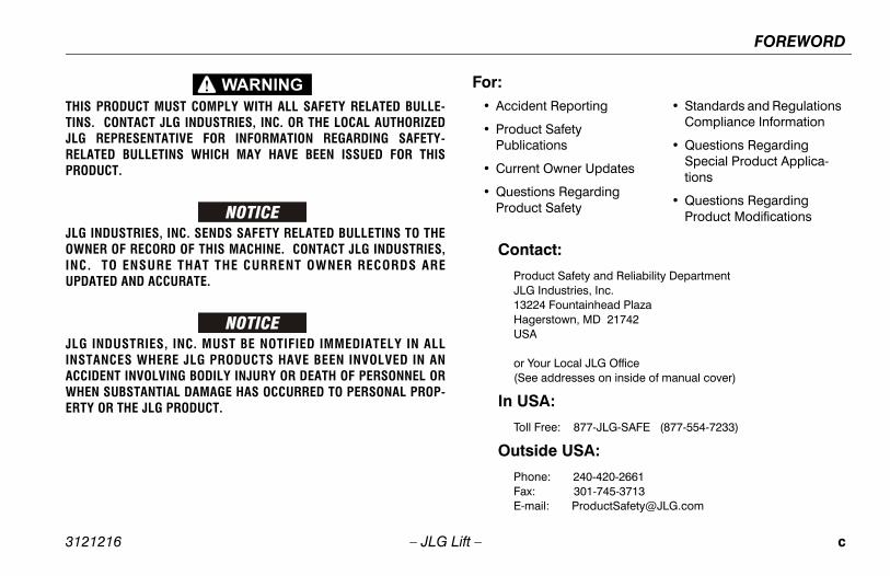
• Standards and Regulations Compliance Information
• Questions Regarding Special Product Applica-tions
• Questions Regarding Product Modifications
3121216 – JLG Lift –
THIS PRODUCT MUST COMPLY WITH ALL SAFETY RELATED BULLE-TINS. CONTACT JLG INDUSTRIES, INC. OR THE LOCAL AUTHORIZEDJLG REPRESENTATIVE FOR INFORMATION REGARDING SAFETY-RELATED BULLETINS WHICH MAY HAVE BEEN ISSUED FOR THISPRODUCT.
JLG INDUSTRIES, INC. SENDS SAFETY RELATED BULLETINS TO THEOWNER OF RECORD OF THIS MACHINE. CONTACT JLG INDUSTRIES,INC. TO ENSURE THAT THE CURRENT OWNER RECORDS AREUPDATED AND ACCURATE.
JLG INDUSTRIES, INC. MUST BE NOTIFIED IMMEDIATELY IN ALLINSTANCES WHERE JLG PRODUCTS HAVE BEEN INVOLVED IN ANACCIDENT INVOLVING BODILY INJURY OR DEATH OF PERSONNEL ORWHEN SUBSTANTIAL DAMAGE HAS OCCURRED TO PERSONAL PROP-ERTY OR THE JLG PRODUCT.
Cont
ProdJLG1322HagUSA
or Y(See
In US
Toll
Outs
PhoFax:E-m
For:• Accide
• ProducPublica
• Curren
• QuestiProduc

FOREWORD
d 3121216
O
R
R
R
R
R
R
R
R
– JLG Lift –
REVISION LOG
riginal Issue - June 8, 2005
evised - October 14, 2005
evised - February 8, 2006
evised - May 24, 2006
evised - July 31, 2007
evised - October 8, 2008
evised - November 5, 2009
evised - October 6, 2011
evised - May 25, 2012

TABLE OF CONTENTS
3121 i
SEC - PARAGRAPH, SUBJECT PAGE
SEC
SECRATI
Walk-Around inspection . . . . . . . . . . . . . . . . . . . 2-9OSCILLATING AXLE LOCKOUT TEST
(IF EQUIPPED) . . . . . . . . . . . . . . . . . . . . . . . . . . 2-11
- 3 - MACHINE CONTROLS AND INDICATORS
GENERAL . . . . . . . . . . . . . . . . . . . . . . . . . . . . . . . . 3-1CONTROLS AND INDICATORS . . . . . . . . . . . . . . . 3-1
Ground Controls . . . . . . . . . . . . . . . . . . . . . . . . . 3-2Ground Control Indicator Panel . . . . . . . . . . . . . 3-7Platform Station . . . . . . . . . . . . . . . . . . . . . . . . . 3-10Platform Control Indicator Panel . . . . . . . . . . . . 3-16
- 4 - MACHINE OPERATION
DESCRIPTION. . . . . . . . . . . . . . . . . . . . . . . . . . . . . 4-1OPERATING CHARACTERISTICS AND
LIMITATIONS . . . . . . . . . . . . . . . . . . . . . . . . . . . . 4-1Capacities . . . . . . . . . . . . . . . . . . . . . . . . . . . . . . 4-1Stability . . . . . . . . . . . . . . . . . . . . . . . . . . . . . . . . 4-2
ENGINE OPERATION . . . . . . . . . . . . . . . . . . . . . . . 4-4Starting Procedure . . . . . . . . . . . . . . . . . . . . . . . 4-4Shutdown Procedure . . . . . . . . . . . . . . . . . . . . . 4-5
TRAVELING (DRIVING) . . . . . . . . . . . . . . . . . . . . . . 4-5Traveling Forward or Reverse . . . . . . . . . . . . . . . 4-8
216 – JLG Lift –
TION - PARAGRAPH, SUBJECT PAGE SECTION
TION - 1 - SAFETY PRECAUTIONS
1.1 GENERAL . . . . . . . . . . . . . . . . . . . . . . . . . . . . . . . . .1-11.2 PRE-OPERATION . . . . . . . . . . . . . . . . . . . . . . . . . . .1-1
Operator Training and Knowledge. . . . . . . . . . . 1-1Workplace Inspection. . . . . . . . . . . . . . . . . . . . . 1-2Machine Inspection . . . . . . . . . . . . . . . . . . . . . . 1-2
1.3 OPERATION . . . . . . . . . . . . . . . . . . . . . . . . . . . . . . .1-3General . . . . . . . . . . . . . . . . . . . . . . . . . . . . . . . . 1-3Trip and Fall Hazards . . . . . . . . . . . . . . . . . . . . . 1-3Electrocution Hazards . . . . . . . . . . . . . . . . . . . . 1-4Tipping Hazards . . . . . . . . . . . . . . . . . . . . . . . . . 1-6Crushing and Collision Hazards. . . . . . . . . . . . . 1-7
1.4 TOWING, LIFTING, AND HAULING . . . . . . . . . . . . .1-81.5 ADDITIONAL HAZARDS / SAFETY . . . . . . . . . . . . .1-9
TION - 2 - USER RESPONSIBILITIES, MACHINE PREPA-ON, AND INSPECTION
2.1 PERSONNEL TRAINING . . . . . . . . . . . . . . . . . . . . .2-1Operator Training . . . . . . . . . . . . . . . . . . . . . . . . 2-1Training Supervision. . . . . . . . . . . . . . . . . . . . . . 2-1Operator Responsibility . . . . . . . . . . . . . . . . . . . 2-1
2.2 PREPARATION, INSPECTION, AND MAINTENANCE . . . . . . . . . . . . . . . . . . . . . . . . . . .2-2Pre-Start Inspection . . . . . . . . . . . . . . . . . . . . . . 2-5Functional Check . . . . . . . . . . . . . . . . . . . . . . . . 2-6
2.3
SECTION
3.13.2
SECTION
4.14.2
4.3
4.4

TABLE OF CONTENTS
ii 3121216
SECTIO RAGRAPH, SUBJECT PAGE
4.54.64.7
4.8
4.9
4.10
T DOWN AND PARK . . . . . . . . . . . . . . . . . . . .4-14DOWN AND LIFTING . . . . . . . . . . . . . . . . . . . .4-14ING . . . . . . . . . . . . . . . . . . . . . . . . . . . . . . . . .4-18
CARDS AND DECALS . . . . . . . . . . . . . . . . . . .4-19
EMERGENCY PROCEDURES
ERAL . . . . . . . . . . . . . . . . . . . . . . . . . . . . . . . . .5-1IDENT NOTIFICATION . . . . . . . . . . . . . . . . . . . .5-1RGENCY OPERATION . . . . . . . . . . . . . . . . . . .5-1
perator Unable to Control Machine . . . . . . . . . 5-1atform or Boom Caught Overhead . . . . . . . . . 5-2ERGENCY TOWING PROCEDURES. . . . . . . . .5-2
GENERAL SPECIFICATIONS & OPERATOR E
ODUCTION. . . . . . . . . . . . . . . . . . . . . . . . . . . .6-1RATING SPECIFICATIONS. . . . . . . . . . . . . . . .6-1
apacities . . . . . . . . . . . . . . . . . . . . . . . . . . . . . . 6-5gine. . . . . . . . . . . . . . . . . . . . . . . . . . . . . . . . . 6-6
res . . . . . . . . . . . . . . . . . . . . . . . . . . . . . . . . . . 6-8ydraulic Oil . . . . . . . . . . . . . . . . . . . . . . . . . . . . 6-9ritical Stability Weights . . . . . . . . . . . . . . . . . . 6-12rial Number Location . . . . . . . . . . . . . . . . . . 6-13
– JLG Lift –
N - PARAGRAPH, SUBJECT PAGE SECTION - PA
STEERING . . . . . . . . . . . . . . . . . . . . . . . . . . . . . . . . 4-9PARKING AND STOWING . . . . . . . . . . . . . . . . . . . . 4-9PLATFORM . . . . . . . . . . . . . . . . . . . . . . . . . . . . . . . 4-9
Loading from Ground Level . . . . . . . . . . . . . . . . 4-9Loading From Positions Above Ground Level . 4-9Platform Level Adjustment . . . . . . . . . . . . . . . . 4-10Platform Rotation . . . . . . . . . . . . . . . . . . . . . . . 4-10
BOOM . . . . . . . . . . . . . . . . . . . . . . . . . . . . . . . . . . 4-10Swinging the Boom . . . . . . . . . . . . . . . . . . . . . 4-11Raising and Lowering the Main Boom . . . . . . 4-11Telescoping the Main Boom . . . . . . . . . . . . . . 4-11
AUXILIARY POWER - NON ADE EQUIPPED MACHINES . . . . . . . . . . . . . . . . . . . . . . . . . . . . . 4-12Activating from the Platform Control Station . . 4-12Activating from the Ground Control Station . . 4-12
AUXILIARY POWER - ADE EQUIPPED MACHINES . . . . . . . . . . . . . . . . . . . . . . . . . . . . . 4-13Activating from the Platform Control Station . . 4-13Activating from the Ground Control Station . . 4-13
4.11 SHU4.12 TIE 4.13 TOW4.14 PLA
SECTION - 5 -
5.1 GEN5.2 INC5.3 EME
OPl
5.4 EM
SECTION - 6 - MAINTENANC
6.1 INTR6.2 OPE
CEnTiHCSe

TABLE OF CONTENTS
3121 iii
SEC - PARAGRAPH, SUBJECT PAGE
SEC
LIST OF FIGURES
Basic Nomenclature . . . . . . . . . . . . . . . . . . . . . . . . 2-4Daily Walk-Around Inspection - Sheet 1 of 3 . . . . . 2-8Daily Walk-Around Inspection - Sheet 2 of 3 . . . . . 2-9Daily Walk-Around Inspection - Sheet 3 of 3 . . . . 2-10Ground Control Station - S Models . . . . . . . . . . . . 3-3Ground Control Station - SJ Models . . . . . . . . . . . 3-4Ground Control Indicator Panel (Prior to S/N 93233) . . . . . . . . . . . . . . . . . . . . . . . 3-7
Ground Control Indicator Panel (S/N 93233 to Present) . . . . . . . . . . . . . . . . . . . . . 3-8
Platform Control Console . . . . . . . . . . . . . . . . . . . 3-11Platform Control Console - w/Drive Orientation . . 3-12Platform Control Indicator Panel . . . . . . . . . . . . . 3-17Platform Control Indicator Panel - w/Drive Orientation. . . . . . . . . . . . . . . . . . . . . . . . . . . . . . 3-17
Position Of Least Backward Stability . . . . . . . . . . . 4-2Position Of Least Forward Stability . . . . . . . . . . . . 4-3Grades and Sideslopes . . . . . . . . . . . . . . . . . . . . . 4-7Machine Tie Down - 400S Models . . . . . . . . . . . . 4-15Machine Tie Down - 460SJ Models . . . . . . . . . . . 4-16Lifting and Tie Down . . . . . . . . . . . . . . . . . . . . . . . 4-17Drive Disconnect Hub. . . . . . . . . . . . . . . . . . . . . . 4-18Decal Installation - Sheet 1 of 4 . . . . . . . . . . . . . . 4-20Decal Installation - Sheet 2 of 4 . . . . . . . . . . . . . . 4-21
216 – JLG Lift –
TION - PARAGRAPH, SUBJECT PAGE SECTION
6.3 OPERATOR MAINTENANCE . . . . . . . . . . . . . . . . .6-256.4 TIRES & WHEELS . . . . . . . . . . . . . . . . . . . . . . . . .6-31
Tire Inflation . . . . . . . . . . . . . . . . . . . . . . . . . . . 6-31Tire Damage . . . . . . . . . . . . . . . . . . . . . . . . . . . 6-31Tire Replacement . . . . . . . . . . . . . . . . . . . . . . . 6-32Wheel Replacement . . . . . . . . . . . . . . . . . . . . . 6-32Wheel Installation . . . . . . . . . . . . . . . . . . . . . . . 6-33
6.5 DRAINING OIL BUILD UP FROM THE PROPANE REGULATOR (PRIOR TO S/N 0300109274) . . . . . . . . . . . . . . . . . . . . . . . . .6-34
6.6 PROPANE FUEL FILTER REPLACEMENT. . . . . . .6-36Removal . . . . . . . . . . . . . . . . . . . . . . . . . . . . . . 6-36Installation. . . . . . . . . . . . . . . . . . . . . . . . . . . . . 6-36
6.7 PROPANE FUEL SYSTEM PRESSURE RELIEF . .6-386.8 SUPPLEMENTAL INFORMATION . . . . . . . . . . . . .6-38
TION - 7 - INSPECTION AND REPAIR LOG
2-1.2-2.2-3.2-4.3-1.3-2.3-3.
3-4.
3-5.3-6.3-7.3-8.
4-1.4-2.4-3.4-4.4-5.4-6.4-7.4-8.4-9.

TABLE OF CONTENTS
iv 3121216
SECTIO RAGRAPH, SUBJECT PAGE
4-10.4-11.6-1.6-2.
6-3.
6-4.
6-5.
6-6.
6-7.
6-8.
6-9.
6-10.
6-11.
6-12.6-13.
LIST OF TABLES
mum Approach Distances (M.A.D.). . . . . . . . . 1-5ufort Scale (For Reference Only) . . . . . . . . . . 1-10ection and Maintenance Table . . . . . . . . . . . . 2-3als - 400S with 500 lb (227 or 230 kg) acity . . . . . . . . . . . . . . . . . . . . . . . . . . . . . . . . 4-24als - 400S with 750 lb (340 kg) Capacity . . . . 4-28als - 460SJ . . . . . . . . . . . . . . . . . . . . . . . . . . . 4-32rating Specifications - 400S - Prior to S/N 142870 . . . . . . . . . . . . . . . . . . . . . . . . . . . . . . 6-1rating Specifications - 400S - S/N 0300142870 to ent . . . . . . . . . . . . . . . . . . . . . . . . . . . . . . . . . . 6-2rating Specifications - 460SJ - Prior to S/N 142870 . . . . . . . . . . . . . . . . . . . . . . . . . . . . . . 6-3rating Specifications - 460SJ - S/N 0300142870 to ent . . . . . . . . . . . . . . . . . . . . . . . . . . . . . . . . . . 6-4acities . . . . . . . . . . . . . . . . . . . . . . . . . . . . . . . . 6-5 LRG-425 (Gas or Dual Fuel) . . . . . . . . . . . . . 6-6tz F3M1011F/F3M2011F/D2011L03 . . . . . . . . 6-6u 4LE1 . . . . . . . . . . . . . . . . . . . . . . . . . . . . . . . 6-7rpillar 3024/C2.2 . . . . . . . . . . . . . . . . . . . . . . . 6-73.0L . . . . . . . . . . . . . . . . . . . . . . . . . . . . . . . . . 6-7ins 404D-22 . . . . . . . . . . . . . . . . . . . . . . . . . . . 6-8 . . . . . . . . . . . . . . . . . . . . . . . . . . . . . . . . . . . . 6-8
raulic Oil . . . . . . . . . . . . . . . . . . . . . . . . . . . . . . 6-9
– JLG Lift –
N - PARAGRAPH, SUBJECT PAGE SECTION - PA
Decal Installation - Sheet 3 of 4. . . . . . . . . . . . . . . 4-22Decal Installation - Sheet 4 of 4. . . . . . . . . . . . . . . 4-23Serial Number Location. . . . . . . . . . . . . . . . . . . . . 6-13Engine Operating Temperature Specifications - Deutz - Sheet 1 of 2 . . . . . . . . . . . . . . . . . . . . . . . 6-14
Engine Operating Temperature Specifications - Deutz - Sheet 2 of 2 . . . . . . . . . . . . . . . . . . . . . . . 6-15
Engine Operating Temperature Specifications - Ford - Sheet 1 of 2 . . . . . . . . . . . . . . . . . . . . . . . . 6-16
Engine Operating Temperature Specifications - Ford - Sheet 2 of 2 . . . . . . . . . . . . . . . . . . . . . . . . 6-17
Engine Operating Temperature Specifications - Caterpillar - Sheet 1 of 2 . . . . . . . . . . . . . . . . . . . 6-18
Engine Operating Temperature Specifications - Caterpillar - Sheet 2 of 2 . . . . . . . . . . . . . . . . . . . 6-19
Engine Operating Temperature Specifications - GM - Sheet 1 of 2. . . . . . . . . . . . . . . . . . . . . . . . . 6-20
Engine Operating Temperature Specifications - GM - Sheet 2 of 2. . . . . . . . . . . . . . . . . . . . . . . . . 6-21
Engine Operating Temperature Specifications - Perkins - Sheet 1 of 2. . . . . . . . . . . . . . . . . . . . . . 6-22
Engine Operating Temperature Specifications - Perkins - Sheet 2 of 2. . . . . . . . . . . . . . . . . . . . . . 6-23
Operator Maintenance and Lubrication Diagram . 6-24Filter Lock Assembly . . . . . . . . . . . . . . . . . . . . . . . 6-37
1-1 Mini1-2 Bea2-1 Insp4-1 Dec
Cap4-2 Dec4-3 Dec6-1 Ope
03006-2 Ope
Pres6-3 Ope
03006-4 Ope
Pres6-5 Cap6-6 Ford6-7 Deu6-8 Isuz6-9 Cate6-10 GM 6-11 Perk6-12 Tires6-13 Hyd

TABLE OF CONTENTS
3121 v
SEC - PARAGRAPH, SUBJECT PAGE
216 – JLG Lift –
TION - PARAGRAPH, SUBJECT PAGE SECTION
6-14 Mobilfluid 424 Specs . . . . . . . . . . . . . . . . . . . . . . . 6-96-15 UCon Hydrolube HP-5046 . . . . . . . . . . . . . . . . . . 6-106-16 Mobil EAL 224H Specs. . . . . . . . . . . . . . . . . . . . . 6-106-17 Mobil EAL Envirosyn H Specs . . . . . . . . . . . . . . . 6-116-18 Exxon Univis HVI 26 Specs . . . . . . . . . . . . . . . . . 6-116-19 Critical Stability Weights. . . . . . . . . . . . . . . . . . . . 6-126-20 Lubrication Specifications . . . . . . . . . . . . . . . . . . 6-256-21 Wheel Torque Chart . . . . . . . . . . . . . . . . . . . . . . . 6-347-1 Inspection and Repair Log . . . . . . . . . . . . . . . . . . . 7-1

TABLE OF CONTENTS
vi 3121216
SECTIO RAGRAPH, SUBJECT PAGE
lly.
– JLG Lift –
N - PARAGRAPH, SUBJECT PAGE SECTION - PA
This page left blank intentiona

SECTION 1 - SAFETY PRECAUTIONS
1-1
CAUTIONS
E-OPERATION
Training and Knowledged and understand this manual before operating thehine.
not operate this machine until complete training is per-ed by authorized persons.
y authorized and qualified personnel can operate thehine.
3121216 – JLG Lift –
SECTION 1. SAFETY PRE
1.1 GENERALThis section outlines the necessary precautions for properand safe machine operation and maintenance. For propermachine use, it is mandatory that a daily routine is estab-lished based on the content of this manual. A maintenanceprogram, using the information provided in this manual andthe Service and Maintenance Manual, must also be estab-lished by a qualified person and followed to ensure themachine is safe to operate.
The owner/user/operator/lessor/lessee of the machineshould not operate the machine until this manual has beenread, training is accomplished, and operation of the machinehas been completed under the supervision of an experi-enced and qualified operator.
If there are any questions with regard to safety, training,inspection, maintenance, application, and operation, pleasecontact JLG Industries, Inc. (“JLG”).
FAILURE TO COMPLY WITH THE SAFETY PRECAUTIONS LISTED INTHIS MANUAL COULD RESULT IN MACHINE DAMAGE, PROPERTY DAM-AGE, PERSONAL INJURY OR DEATH.
1.2 PR
Operator• Rea
mac
• Do form
• Onlmac

SECTION 1 - SAFETY PRECAUTIONS
1-2 3121216
Wo
pection achine operation, perform inspections and func-
hecks. Refer to Section 2 of this manual for instructions.
perate this machine until it has been serviced anded according to requirements specified in theand Maintenance Manual.
the footswitch and all other safety devices areg properly. Modification of these devices is aolation.
R ALTERATION OF AN AERIAL WORK PLATFORMNLY WITH WRITTEN PERMISSION FROM THE MANU-
perate any machine on which safety or instruction or decals are missing or illegible.
ny buildup of debris on the platform floor. Keep, grease, and other slippery substances from foot-d platform floor.
– JLG Lift –
• Read, understand, and obey all DANGERS, WARNINGS,CAUTIONS, and operating instructions on the machineand in this manual.
• Use the machine in a manner which is within the scope ofits intended application set by JLG.
• All operating personnel must be familiar with the emer-gency controls and emergency operation of the machineas specified in this manual.
• Read, understand, and obey all applicable employer,local, and governmental regulations as they pertain tooperation of the machine.
rkplace Inspection• The operator is to take safety measures to avoid all haz-
ards in the work area prior to machine operation.
• Do not operate or raise the platform while on trucks, trail-ers, railway cars, floating vessels, scaffolds or other equip-ment unless approved in writing by JLG.
• Do not operate the machine in hazardous environmentsunless approved for that purpose by JLG.
• Be sure that the ground conditions are able to support themaximum load shown on the decals located on themachine.
Machine Ins• Before m
tional cdetailed
• Do not omaintainService
• Be sureoperatinsafety vi
MODIFICATION OSHALL BE MADE OFACTURER
• Do not oplacards
• Avoid amud, oilwear an

SECTION 1 - SAFETY PRECAUTIONS
1-3
plies or tools which extend outside the platform arehibited unless approved by JLG.
en driving, always position boom over rear axle in line the direction of travel. Remember, if boom is over thet axle, steer and drive functions will be reversed.
not assist a stuck or disabled machine by pushing,ing, or by using boom functions. Only pull the unit the tie-down lugs on the chassis.
not place boom or platform against any structure tody the platform or to support the structure.
w boom and shut off all power before leaving machine.
Fall Hazards operation, occupants in the platform must wear a fullarness with a lanyard attached to an authorized lan-
nchorage point. Attach only one (1) lanyard per lan-nchorage point.
3121216 – JLG Lift –
1.3 OPERATION
General • Do not use the machine for any purpose other than posi-
tioning personnel, their tools, and equipment.
• Never operate a machine that is not working properly. If amalfunctions occurs, shut down the machine.
• Never slam a control switch or lever through neutral to anopposite direction. Always return switch to neutral andstop before moving the switch to the next function. Oper-ate controls with slow and even pressure.
• Hydraulic cylinders should never be left fully extended orfully retracted before shutdown or for long periods of time.
• Do not allow personnel to tamper with or operate themachine from the ground with personnel in the platform,except in an emergency.
• Do not carry materials directly on platform railing. ContactJLG for approved material handling accessories.
• When two or more persons are in the platform, the opera-tor shall be responsible for all machine operations.
• Always ensure that power tools are properly stowed andnever left hanging by their cord from the platform workarea.
• Suppro
• Whwithfron
• Do pullfrom
• Do stea
• Sto
Trip and Duringbody hyard ayard a

SECTION 1 - SAFETY PRECAUTIONS
1-4 3121216
reme caution when entering or leaving platform. that the boom is fully lowered. It may be neces-elescope out to position the platform closer to thefor entry/exit. Face the machine, maintain “threentact” with the machine, using two hands and one
o feet and one hand during entry and exit.
n Hazardschine is not insulated and does not provide pro-rom contact or proximity to electrical current.
– JLG Lift –
• Before operating the machine, make sure all gates areclosed and fastened in their proper position.
• Keep both feet firmly positioned on the platform floor at alltimes. Never use ladders, boxes, steps, planks, or similaritems on platform to provide additional reach.
• Never use the boom assembly to enter or leave the plat-form.
• Use extBe suresary to tground point cofoot or tw
Electrocutio• This ma
tection f
SECTION 1 - SAFETY PRECAUTIONS
1-5
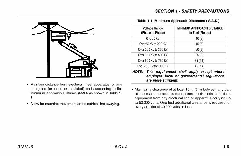
in a clearance of at least 10 ft. (3m) between any part machine and its occupants, their tools, and their
ent from any electrical line or apparatus carrying up00 volts. One foot additional clearance is required for
additional 30,000 volts or less.
1-1. Minimum Approach Distances (M.A.D.)
oltage Rangease to Phase)
MINIMUM APPROACH DISTANCEin Feet (Meters)
0 to 50 KV 10 (3)
r 50KV to 200 KV 15 (5)
200 KV to 350 KV 20 (6)
350 KV to 500 KV 25 (8)
500 KV to 750 KV 35 (11)
50 KV to 1000 KV 45 (14)
This requirement shall apply except whereemployer, local or governmental regulationsare more stringent.
3121216 – JLG Lift –
• Maintain distance from electrical lines, apparatus, or anyenergized (exposed or insulated) parts according to theMinimum Approach Distance (MAD) as shown in Table 1-1.
• Allow for machine movement and electrical line swaying.
• Maintaof theequipmto 50,0every
Table
V(Ph
Ove
Over
Over
Over
Over 7
NOTE:

SECTION 1 - SAFETY PRECAUTIONS
1-6 3121216
•
DO ZONENE
ardsr should be familiar with the surface before driv-not exceed the allowable sideslope and grade
iving.
– JLG Lift –
The minimum approach distance may be reduced if insulat-ing barriers are installed to prevent contact, and the barriersare rated for the voltage of the line being guarded. Thesebarriers shall not be part of (or attached to) the machine. Theminimum approach distance shall be reduced to a distancewithin the designed working dimensions of the insulatingbarrier. This determination shall be made by a qualified per-son in accordance with the employer, local, or governmentalrequirements for work practices near energized equipment
NOT MANEUVER MACHINE OR PERSONNEL INSIDE PROHIBITEDE (MAD). ASSUME ALL ELECTRICAL PARTS AND WIRING ARERGIZED UNLESS KNOWN OTHERWISE.
Tipping Haz• The use
ing. Do while dr

SECTION 1 - SAFETY PRECAUTIONS
1-7
oom assembly or platform is in a position that one ore wheels are off the ground, all persons must beoved before attempting to stabilize the machine. Usees, forklift trucks, or other appropriate equipment toilize machine.
and Collision Hazardsroved head gear must be worn by all operating and
und personnel.
ck work area for clearances overhead, on sides, andom of platform when lifting or lowering platform, anding.
ing operation, keep all body parts inside platform rail-
3121216 – JLG Lift –
• Do not elevate platform or drive with platform elevatedwhile on a sloping, uneven, or soft surface.
• Before driving on floors, bridges, trucks, and other sur-faces, check allowable capacity of the surfaces.
• Never exceed the maximum platform capacity. Distributeloads evenly on platform floor.
• Do not raise the platform or drive from an elevated posi-tion unless the machine is on firm, level and smooth sur-faces.
• Keep the chassis of the machine at least 2 ft. (0.6m) fromholes, bumps, drop-offs, obstructions, debris, concealedholes, and other potential hazards on the floor/surface.
• Do not push or pull any object with the boom.
• Never attempt to use the machine as a crane. Do not tie-off machine to any adjacent structure.
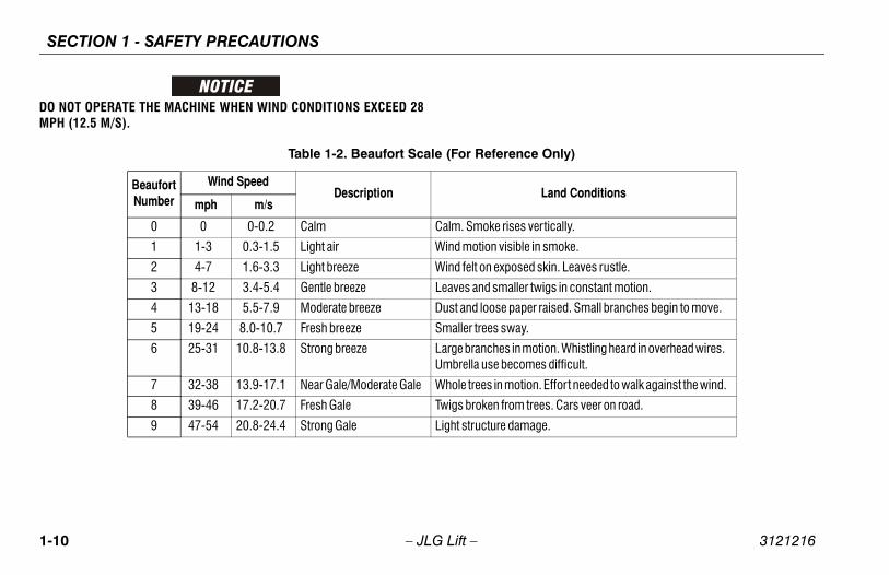
• Do not operate the machine when wind conditions exceed28 mph (12.5 m/s). Refer to Table 1-2, Beaufort Scale (ForReference Only).
• Do not increase the surface area of the platform or theload. Increase of the area exposed to the wind willdecrease stability.
• Do not increase the platform size with unauthorized deckextensions or attachments.
• If bmorremcranstab
Crushing• App
gro
• Chebottdriv
• During.

SECTION 1 - SAFETY PRECAUTIONS
1-8 3121216
G, LIFTING, AND HAULINGllow personnel in platform while towing, lifting, or
chine should not be towed, except in the event ofcy, malfunction, power failure, or loading/unload-
er to the Emergency Procedures section of thisfor emergency towing procedures.
boom is in the stowed position and the turntablerior to towing, lifting or hauling. The platform mustletely empty of tools.
ting machine, lift only at designated areas of the. Lift the unit with equipment of adequate capac-
the Machine Operation section of this manual forormation.
– JLG Lift –
• Use the boom functions, not the drive function, to positionthe platform close to obstacles.
• Always post a lookout when driving in areas where visionis obstructed.
• Keep non-operating personnel at least 6 ft. (1.8m) awayfrom machine during all driving and swing operations.
• Limit travel speed according to conditions of ground sur-face, congestion, visibility, slope, location of personnel,and other factors which may cause collision or injury topersonnel.
• Be aware of stopping distances in all drive speeds. Whendriving in high speed, switch to low speed before stop-ping. Travel grades in low speed only.
• Do not use high speed drive in restricted or close quartersor when driving in reverse.
• Exercise extreme caution at all times to prevent obstaclesfrom striking or interfering with operating controls and per-sons in the platform.
• Be sure that operators of other overhead and floor levelmachines are aware of the aerial work platform’s pres-ence. Disconnect power to overhead cranes.
• Warn personnel not to work, stand, or walk under a raisedboom or platform. Position barricades on floor if neces-sary.
1.4 TOWIN• Never a
hauling.
• This maemergening. Refmanual
• Ensure locked pbe comp
• When lifmachineity.
• Refer tolifting inf

SECTION 1 - SAFETY PRECAUTIONS
1-9
not refuel the machine with the engine running.
tery fluid is highly corrosive. Avoid contact with skin clothing at all times.
rge batteries only in a well ventilated area.
3121216 – JLG Lift –
1.5 ADDITIONAL HAZARDS / SAFETY• Do not use machine as a ground for welding.
• When performing welding or metal cutting operations,precautions must be taken to protect the chassis fromdirect exposure to weld and metal cutting spatter.
• Do
• Batand
• Cha
SECTION 1 - SAFETY PRECAUTIONS
1-1 3121216
DO NMPH
Only)
Land Conditions
ertically.
n smoke.
skin. Leaves rustle.
wigs in constant motion.
r raised. Small branches begin to move.
tion. Whistling heard in overhead wires. es difficult.
n. Effort needed to walk against the wind.
ees. Cars veer on road.
ge.
0 – JLG Lift –
OT OPERATE THE MACHINE WHEN WIND CONDITIONS EXCEED 28 (12.5 M/S).
Table 1-2. Beaufort Scale (For Reference
Beaufort Number
Wind SpeedDescription
mph m/s
0 0 0-0.2 Calm Calm. Smoke rises v
1 1-3 0.3-1.5 Light air Wind motion visible i
2 4-7 1.6-3.3 Light breeze Wind felt on exposed
3 8-12 3.4-5.4 Gentle breeze Leaves and smaller t
4 13-18 5.5-7.9 Moderate breeze Dust and loose pape
5 19-24 8.0-10.7 Fresh breeze Smaller trees sway.
6 25-31 10.8-13.8 Strong breeze Large branches in moUmbrella use becom
7 32-38 13.9-17.1 Near Gale/Moderate Gale Whole trees in motio
8 39-46 17.2-20.7 Fresh Gale Twigs broken from tr
9 47-54 20.8-24.4 Strong Gale Light structure dama

CHINE PREPARATION, AND INSPECTION
2-1
PREPARATION, AND INSPECTION
he safest means to operate the machine where over-ead obstructions, other moving equipment, andbstacles, depressions, holes, drop-offs.
eans to avoid the hazards of unprotected electricalonductors.
pecific job requirements or machine application.
Supervisionng must be done under the supervision of a qualifiedn in an open area free of obstructions until the traineeeveloped the ability to safely control and operate theine.
r Responsibilityperator must be instructed that he/she has the respon-y and authority to shut down the machine in case of anction or other unsafe condition of either the machine job site.
SECTION 2 - USER RESPONSIBILITIES, MA
3121216 – JLG Lift –
SECTION 2. USER RESPONSIBILITIES, MACHINE
2.1 PERSONNEL TRAININGThe aerial platform is a personnel handling device; so it isnecessary that it be operated and maintained only bytrained personnel.
Persons under the influence of drugs or alcohol or who aresubject to seizures, dizziness or loss of physical controlmust not operate this machine.
Operator TrainingOperator training must cover:
1. Use and limitations of the controls in the platform andat the ground, emergency controls and safety systems.
2. Control labels, instructions, and warnings on themachine.
3. Rules of the employer and government regulations.
4. Use of approved fall protection device.
5. Enough knowledge of the mechanical operation of themachine to recognize a malfunction or potential mal-function.
6. Tho
7. Mc
8. S
TrainingTrainipersohas dmach
OperatoThe osibilitmalfuor the

SECTION 2 - USER RESPONSIBILITIES, MACHINE PREPARATION, AND INSPECTION
2-2 3121216
2.2S, INC. RECOGNIZES A FACTORY-TRAINED SERVICE A PERSON WHO HAS SUCCESSFULLY COMPLETEDE TRAINING SCHOOL FOR THE SPECIFIC JLG PROD-
– JLG Lift –
PREPARATION, INSPECTION, AND MAINTENANCE
The following table covers the periodic machine inspectionsand maintenance required by JLG Industries, Inc. Consultlocal regulations for further requirements for aerial workplatforms. The frequency of inspections and maintenancemust be increased as necessary when the machine is usedin a harsh or hostile environment, if the machine is usedwith increased frequency, or if the machine is used in asevere manner.
JLG INDUSTRIETECHNICIAN ASTHE JLG SERVICUCT MODEL.

CHINE PREPARATION, AND INSPECTION
2-3
nce Table
ityService
QualificationReference
User or Operator Operator and Safety Man-ual
r, o r Qualified JLG Mechanic
Service and MaintenanceManual and applicableJLG inspection form
r, o r Qualified JLG Mechanic
Service and MaintenanceManual and applicableJLG inspection form
r, o r Fac to ry -Tra inedService Technician(Recommended)
Service and MaintenanceManual and applicableJLG inspection form
r, o r Qualified JLG Mechanic
Service and MaintenanceManual
tenance Manual to perform inspections.
SECTION 2 - USER RESPONSIBILITIES, MA
3121216 – JLG Lift –
Table 2-1.Inspection and Maintena
Type Frequency PrimaryResponsibil
Pre-Start Inspec-tion
Before using each day; or whenever there’s an Operator change.
User or Operator
Pre -De l i ve ryInspection (SeeNote)
Before each sale, lease, or rental delivery. Owner, Dea leUser
Frequen tInspection(See Note)
In service for 3 months or 150 hours, which-ever comes first; or
Out of service for a period of more than 3months; or
Purchased used.
Owner, Dea leUser
Annual MachineInspection(See Note)
Annually, no later than 13 months from thedate of prior inspection.
Owner, Dea leUser
Preven ta t i veMaintenance
At intervals as specified in the Service andMaintenance Manual.
Owner, Dea leUser
NOTE: Inspection forms are available from JLG. Use the Service and Main
SECTION 2 - USER RESPONSIBILITIES, MACHINE PREPARATION, AND INSPECTION
2-4 3121216
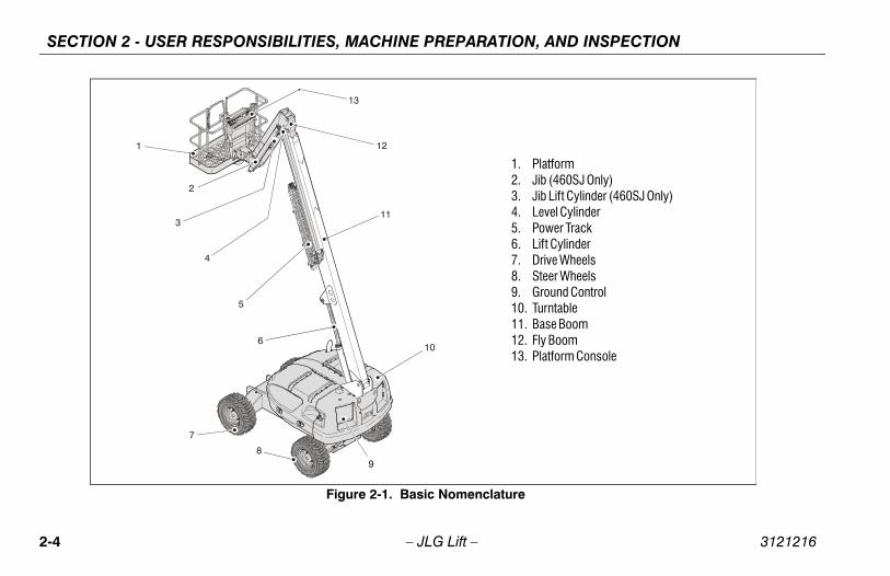
latformib (460SJ Only)ib Lift Cylinder (460SJ Only)evel Cylinderower Trackift Cylinderrive Wheelsteer Wheelsround Controlurntablease Boomly Boomlatform Console
– JLG Lift –
13
12
11
10
7
8
3
2
6
5
4
Figure 2-1. Basic Nomenclature
1. P2. J3. J4. L5. P6. L7. D8. S9. G10. T11. B12. F13. P
CHINE PREPARATION, AND INSPECTION
2-5
ngine Oil Supply - Ensure the engine oil level is at theull mark on the dipstick and the filler cap is secure.
ydraulic Oil – Check the hydraulic oil level. Ensureydraulic oil is added as required.
ccessories/Attachments - Reference the Operatornd Safety Manual of each attachment or accessorystalled upon the machine for specific inspection,peration, and maintenance instructions.
unction Check – Once the “Walk-Around” Inspection complete, perform a functional check of all systems an area free of overhead and ground level obstruc-
ions. Refer to Section 4 for more specific operatingstructions.
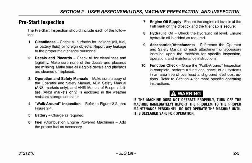
CHINE DOES NOT OPERATE PROPERLY, TURN OFF THEMMEDIATELY! REPORT THE PROBLEM TO THE PROPERCE PERSONNEL. DO NOT OPERATE THE MACHINE UNTILRED SAFE FOR OPERATION.
SECTION 2 - USER RESPONSIBILITIES, MA
3121216 – JLG Lift –
Pre-Start InspectionThe Pre-Start Inspection should include each of the follow-ing:
1. Cleanliness – Check all surfaces for leakage (oil, fuel,or battery fluid) or foreign objects. Report any leakageto the proper maintenance personnel.
2. Decals and Placards – Check all for cleanliness andlegibility. Make sure none of the decals and placardsare missing. Make sure all illegible decals and placardsare cleaned or replaced.
3. Operation and Safety Manuals – Make sure a copy ofthe Operator and Safety Manual, AEM Safety Manual(ANSI markets only), and ANSI Manual of Responsibili-ties (ANSI markets only) is enclosed in the weatherresistant storage container.
4. “Walk-Around” Inspection – Refer to Figure 2-2. thruFigure 2-4.
5. Battery – Charge as required.
6. Fuel (Combustion Engine Powered Machines) – Addthe proper fuel as necessary.
7. EF
8. Hh
9. Aaino
10. Fisintin
IF THE MAMACHINE IMAINTENANIT IS DECLA

SECTION 2 - USER RESPONSIBILITIES, MACHINE PREPARATION, AND INSPECTION
2-6 3121216
Fun le, manually activate the indicator light by com-ing any one of the three tilt indicator mountings. If the light does not illuminate, shut down
ine and contact a qualified service techniciane continuing operation.
p 5 is applicable for machines built from S/N718 to present.
k the chassis out of level indicator located on therm control console by driving, with the machine inposition, up a suitable ramp of at least 5° slope.k the out of level indicator, with the machine onmp. If the light does not illuminate, return the
ine to a level surface, shut down the machine, andct a qualified technician before resuming opera-
k that platform self-leveling system functions prop-uring raising and lowering of boom.
k rotator for smooth operation and assure plat-will rotate 90 degrees in both directions from cen- of boom.
forward and reverse; check for proper operation.
k boom horizontal limit switches to see that theyerable and not damaged. Raise and lower Boom.
k for smooth operation.
– JLG Lift –
ctional CheckFirst, using the ground controls, check all functions con-trolled by the ground controls. Next, using the platformcontrols, check all functions controlled by the platformcontrols.
1. Telescope boom IN and OUT several cycles at variousdegrees of elevation lengths. Check for smooth tele-scope operation.
2. Swing turntable to LEFT and RIGHT a minimum of 45degrees. Check for smooth motion.
NOTE: Step 3 is only applicable for machines prior to S/N0300140365.
3. Check the oscillating axle valve (if equipped) under theturntable at the top front of frame. Observe that thevalve plunger is depressed when turntable is posi-tioned forward, and centered. Swing the turntable untilbracket is past the valve. The plunger should be fullyextended.
NOTE: Step 4 is only applicable for machines prior to S/N61718.
4. With the aid of an assistant to monitor the CHASSISOUT OF LEVEL indicator light on the platform control
consopressspringmachbefor
NOTE: Ste61
5. Checplatfolevel Checthe ramachcontation.
6. Checerly d
7. Checform terline
8. Drive
9. Checare opChec

CHINE PREPARATION, AND INSPECTION
2-7
machine and contact a trained JLG service techni-cian.
uxiliary Power.
perate each function control switch (e.g. Tele, Lift, andwing) to ensure they function in both directions usinguxiliary power.
round Controls.
lace Ground/Platform Select switch to Ground. Startngine. Platform controls should not operate.
SECTION 2 - USER RESPONSIBILITIES, MA
3121216 – JLG Lift –
NOTE: When the boom is raised above horizontal, high drivespeed is cut out.
10. Steer left and right; check for proper operation.
11. Footswitch.
FOOTSWITCH MUST BE ADJUSTED SO THAT FUNCTIONS WILL OPER-ATE WHEN PEDAL IS APPROXIMATELY AT ITS CENTER OF TRAVEL. IFSWITCH OPERATES WITHIN LAST 1/4" OF TRAVEL, TOP OR BOTTOM,IT SHOULD BE ADJUSTED.
a. Activate hydraulic system, by depressing foot-switch. Operate Telescope and hold control.Remove foot from footswitch, motion should stop.If it does not, shut down machine and contact atrained JLG service technician.
b. With footswitch depressed, operate Lift and holdcontrol. Remove foot from footswitch, motionshould stop. If it does not, shut down machine andcontact a trained JLG service technician.
c. With engine power shut down, depress the foot-switch. Attempt to start engine. Engine should notattempt to start when footswitch is depressed. Ifstarter engages or engine turns over, shut down
12. A
OSa
13. G
Pe

SECTION 2 - USER RESPONSIBILITIES, MACHINE PREPARATION, AND INSPECTION
2-8 3121216
heet 1 of 3
– JLG Lift –
Figure 2-2. Daily Walk-Around Inspection - S
CHINE PREPARATION, AND INSPECTION
2-9
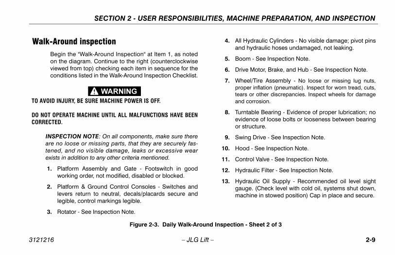
ll Hydraulic Cylinders - No visible damage; pivot pinsnd hydraulic hoses undamaged, not leaking.
oom - See Inspection Note.
rive Motor, Brake, and Hub - See Inspection Note.
heel/Tire Assembly - No loose or missing lug nuts,roper inflation (pneumatic). Inspect for worn tread, cuts,
ears or other discrepancies. Inspect wheels for damagend corrosion.
urntable Bearing - Evidence of proper lubrication; novidence of loose bolts or looseness between bearingr structure.
wing Drive - See Inspection Note.
ood - See Inspection Note.
ontrol Valve - See Inspection Note.
ydraulic Filter - See Inspection Note.
ydraulic Oil Supply - Recommended oil level sightauge. (Check level with cold oil, systems shut down,achine in stowed position) Cap in place and secure.
on - Sheet 2 of 3
SECTION 2 - USER RESPONSIBILITIES, MA
3121216 – JLG Lift –
Walk-Around inspectionBegin the "Walk-Around Inspection" at Item 1, as notedon the diagram. Continue to the right (counterclockwiseviewed from top) checking each item in sequence for theconditions listed in the Walk-Around Inspection Checklist.
TO AVOID INJURY, BE SURE MACHINE POWER IS OFF.
DO NOT OPERATE MACHINE UNTIL ALL MALFUNCTIONS HAVE BEENCORRECTED.
INSPECTION NOTE: On all components, make sure thereare no loose or missing parts, that they are securely fas-tened, and no visible damage, leaks or excessive wearexists in addition to any other criteria mentioned.
1. Platform Assembly and Gate - Footswitch in goodworking order, not modified, disabled or blocked.
2. Platform & Ground Control Consoles - Switches andlevers return to neutral, decals/placards secure andlegible, control markings legible.
3. Rotator - See Inspection Note.
4. Aa
5. B
6. D
7. Wpta
8. Teo
9. S
10. H
11. C
12. H
13. Hgm
Figure 2-3. Daily Walk-Around Inspecti

SECTION 2 - USER RESPONSIBILITIES, MACHINE PREPARATION, AND INSPECTION
2-1 3121216
e Oil Supply - Full mark on dipstick; filler cape.
r and Exhaust System - See Inspection Note.
ary Power Pump - See Inspection Note.
ulic Pump - See Inspection Note.
ry - Proper electrolyte levels; cables tight, no visi-amage or corrosion.
Sheet 3 of 3
0 – JLG Lift –
14. Fuel Supply - Filler cap secure, no visible damage tothe tank or evidence of leaks.
NOTE: Lockout Valves were used prior to S/N 0300140365.
15. Oscillating Axle, Lockout Valves - See Inspection Note.
16. Tie Rod Ends and Steering Spindles - See InspectionNote.
17. Engine Air Filter - Element clean. See Inspection Note.
18. Enginsecur
19. Muffle
20. Auxili
21. Hydra
22. Batteble d
Figure 2-4. Daily Walk-Around Inspection -

CHINE PREPARATION, AND INSPECTION
2-11
arefully activate SWING control lever and positionoom over right side of machine.
ith boom over right side of machine, place DRIVEontrol lever to REVERSE and drive machine off oflock and ramp.
ave an assistant check to see that left front or rightear wheel remains elevated in position off of ground.
arefully activate SWING control lever and return boomo stowed position (centered between drive wheels).
hen boom reaches center, stowed position, lockoutylinders should release and allow wheel to rest onround, it may be necessary activate DRIVE to releaseylinders.
lace the 6 inches (15.2 cm) high block with ascensionamp in front of right front wheel.
lace DRIVE control lever to FORWARD and carefullyrive machine up ascension ramp until right front wheel on top of block.
SECTION 2 - USER RESPONSIBILITIES, MA
3121216 – JLG Lift –
2.3 OSCILLATING AXLE LOCKOUT TEST (IF EQUIPPED)
LOCKOUT SYSTEM TEST MUST BE PERFORMED QUARTERLY, ANYTIME A SYSTEM COMPONENT IS REPLACED, OR WHEN IMPROPERSYSTEM OPERATION IS SUSPECTED.
NOTE: Ensure boom is fully retracted, lowered, and cen-tered between drive wheels prior to beginning lock-out cylinder test.
1. Place a 6 inches (15.2 cm) high block with ascensionramp in front of left front wheel.
2. From platform control station, start engine
3. Place DRIVE control lever to FORWARD position andcarefully drive machine up ascension ramp until leftfront wheel is on top of block.
4. Cb
5. Wcb
6. Hr
7. CtWcgc
8. Pr
9. Pdis

SECTION 2 - USER RESPONSIBILITIES, MACHINE PREPARATION, AND INSPECTION
2-1 3121216
ully activate SWING control lever and return boomwed position (centered between drive wheels). boom reaches center, stowed position, lockouters should release and allow wheel to rest ond, it may be necessary activate DRIVE to releaseers.
out cylinders do not function properly, have quali-ersonnel correct the malfunction prior to any fur-peration.
2 – JLG Lift –
10. With boom over left side, place DRIVE control lever toREVERSE and drive machine off block and ramp.
11. Have an assistant check to see that right front or leftrear wheel remains elevated in position off of ground.
12. Carefto stoWhencylindgrouncylind
13. If lockfied pther o

MACHINE CONTROLS AND INDICATORS
3-1
AND INDICATORS
e indicator panels use different shaped symbols toert the operator to different types of operational situa-ns that could arise. The meaning of those symbols areplained below.
Indicates a potentially hazardous situation, whichif not corrected, could result in serious injury ordeath. This indicator will be red.
Indicates an abnormal operating condition,which if not corrected, may result in machineinterruption or damage. This indicator will be yel-low.
Indicates important information regarding theoperating condition, i.e. procedures essential forsafe operation. This indicator will be green withthe exception of the capacity indicator which willbe green or yellow depending upon platformposition.
SECTION 3 -
3121216 – JLG Lift –
SECTION 3. MACHINE CONTROLS
3.1 GENERAL
THE MANUFACTURER HAS NO DIRECT CONTROL OVER MACHINEAPPLICATION AND OPERATION. THE USER AND OPERATOR ARERESPONSIBLE FOR CONFORMING WITH GOOD SAFETY PRACTICES.
This section provides the necessary information neededto understand control functions.
3.2 CONTROLS AND INDICATORS
NOTE: All machines are equipped with control panels that usesymbols to indicate control functions. On ANSI machinesrefer to decal located on the control box guard in front ofthe control box or by the ground controls for these sym-bols and the corresponding functions.
NOTE: Thaltioex
SECTION 3 - MACHINE CONTROLS AND INDICATORS
3-2 3121216
S3-
TO ATROMOVREL
ipped, the Function Enable switche held down in order to operate Tele-, Swing, Lift, Jib Lift, Platform Levele, and Platform Rotate functions.
rm Rotate.
its rotation of the platform when positioned to the right.
PLATFORM LEVELING OVERRIDE FUNCTION FORG OF THE PLATFORM. INCORRECT USE COULD/OCCUPANTS TO SHIFT OR FALL. FAILURE TO DO SO
IN DEATH OR SERIOUS INJURY.
rm Leveling Override
e position switch allows the operator to adjust theatic self leveling system. This switch is used to
t the platform level in situations such as ascend-escending a grade.
lating Jib Boom. (If Equipped)
es raising and lowering of the jib when posi- up or down.
– JLG Lift –
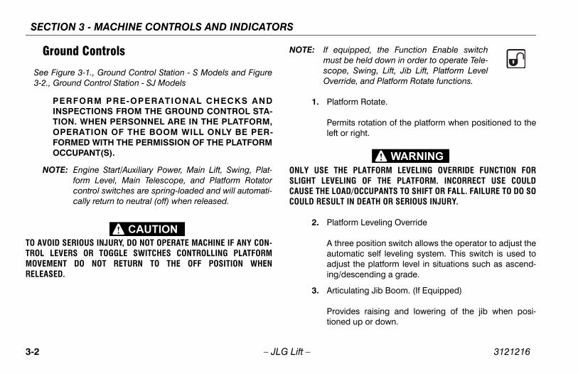
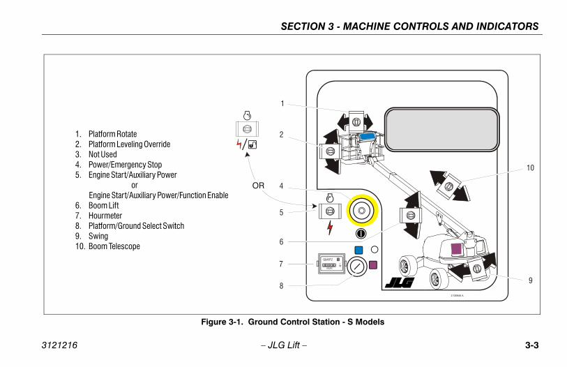
Ground Controls
ee Figure 3-1., Ground Control Station - S Models and Figure2., Ground Control Station - SJ Models
PERFORM PRE-OPERATIONAL CHECKS ANDINSPECTIONS FROM THE GROUND CONTROL STA-TION. WHEN PERSONNEL ARE IN THE PLATFORM,OPERATION OF THE BOOM WILL ONLY BE PER-FORMED WITH THE PERMISSION OF THE PLATFORMOCCUPANT(S).
NOTE: Engine Start/Auxiliary Power, Main Lift, Swing, Plat-form Level, Main Telescope, and Platform Rotatorcontrol switches are spring-loaded and will automati-cally return to neutral (off) when released.
VOID SERIOUS INJURY, DO NOT OPERATE MACHINE IF ANY CON-L LEVERS OR TOGGLE SWITCHES CONTROLLING PLATFORMEMENT DO NOT RETURN TO THE OFF POSITION WHEN
EASED.
NOTE: If equmust bscopeOverrid
1. Platfo
Permleft or
ONLY USE THESLIGHT LEVELINCAUSE THE LOADCOULD RESULT
2. Platfo
A threautomadjusing/d
3. Articu
Providtioned
MACHINE CONTROLS AND INDICATORS
3-3
1706946 A
10
10
9
- S Models
SECTION 3 -
3121216 – JLG Lift –
HOURS1
QUARTZ
OR
7
1
2
4
5
8
6
Figure 3-1. Ground Control Station
1. Platform Rotate2. Platform Leveling Override3. Not Used4. Power/Emergency Stop5. Engine Start/Auxiliary Power or Engine Start/Auxiliary Power/Function Enable6. Boom Lift7. Hourmeter8. Platform/Ground Select Switch9. Swing10. Boom Telescope

SECTION 3 - MACHINE CONTROLS AND INDICATORS
3-4 3121216
1706945 A
10
9
Models
– JLG Lift –
1
HOURS10
QUARTZ
1
7
2
4
5
8
6
3
OR
Figure 3-2. Ground Control Station - SJ
1. Platform Rotate2. Platform Leveling Override3. Articulating Jib Boom4. Power/Emergency Stop5. Engine Start/Auxiliary Power or Engine Start/Auxiliary Power/Function Enable6. Boom Lift7. Hourmeter8. Platform/Ground Select Switch9. Swing10. Boom Telescope

MACHINE CONTROLS AND INDICATORS
3-5
ngine Start/Auxiliary Power Switch orngine Start/ Auxiliary Power Switch /Function Enable.
To start the engine, the switch must be held"UP" until the engine starts.
To use auxiliary power, the switch must beheld “DOWN” for duration of auxiliary pumpuse. Aux power can only be used if the engineis not running.
If equipped, the enable switch must be held"DOWN" to enable all boom controls when theengine is running.
: Auxiliary power only works if there is no oil pressure,and is disabled if engine is running.
SECTION 3 -
3121216 – JLG Lift –
WHEN THE MACHINE IS SHUT DOWN THE MASTER/EMERGENCY STOPSWITCH MUST BE POSITIONED TO THE OFF POSITION TO PREVENTDRAINING THE BATTERY.
4. Power/Emergency Stop Switch.
A two-position red mushroom shaped switch suppliespower to PLATFORM/GROUND SELECT switch whenpulled out (on). When pushed in (off), power is shut offto the PLATFORM/GROUND SELECT switch.
NOTE: When Power/Emergency Stop switch is in the onposition and engine is not running, an alarm willsound, indicating Ignition is on.
5. E E
NOTE

SECTION 3 - MACHINE CONTROLS AND INDICATORS
3-6 3121216
WHEARO
rm/Ground Select Switch.
lies power to the platform control console whenoned to PLATFORM. With the switch in GROUNDon, power is shut off to the platform control con-and only the controls on the ground control panelperable.
th the Platform/Ground Select Switch in the centersition, power is shut off to controls at both operat- stations. Remove the key to prevent the controlsm being actuated.
Control.
es 360 degrees non-continuous turntable rota-hen positioned to the right or left.
Telescope Control.
es extension and retraction of the main boom, positioned to in or out.
– JLG Lift –
N OPERATING THE BOOM ENSURE THERE ARE NO PERSONNELUND OR UNDER PLATFORM.
6. Boom Lift Control.
Provides raising and lowering of the boom when posi-tioned up or down.
7. Hourmeter.
Registers the amount of time the machine has been inuse, with the engine running. By connecting into the oilpressure circuit of the engine, only engine run hoursare recorded. The hourmeter registers up to 9,999.9hours and cannot be reset.
8. Platfo
Supppositipositisole, are o
NOTE: Wipoingfro
9. Swing
Providtion w
10. Main
Providwhen
MACHINE CONTROLS AND INDICATORS
3-7
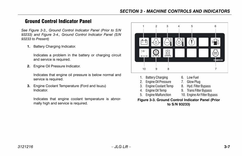
Battery ChargingEngine Oil PressureEngine Coolant TempEngine Oil TempEngine Malfunction
6. Low Fuel7. Glow Plug8. Hyd. Filter Bypass9. Trans Filter Bypass10. Engine Air Filter Bypass
re 3-3. Ground Control Indicator Panel (Prior to S/N 93233)
SECTION 3 -
3121216 – JLG Lift –
Ground Control Indicator Panel
See Figure 3-3., Ground Control Indicator Panel (Prior to S/N93233) and Figure 3-4., Ground Control Indicator Panel (S/N93233 to Present)
1. Battery Charging Indicator.
Indicates a problem in the battery or charging circuitand service is required.
2. Engine Oil Pressure Indicator.
Indicates that engine oil pressure is below normal andservice is required.
3. Engine Coolant Temperature (Ford and Isuzu) Indicator.
Indicates that engine coolant temperature is abnor-mally high and service is required.
1.2.3.4.5.
Figu

SECTION 3 - MACHINE CONTROLS AND INDICATORS
3-8 3121216
e Oil Temperature Indicator (Deutz).
tes that the temperature of the engine oil, whicherves as engine coolant, is abnormally high ande is required.
e Malfunction Indicator. (Ford Only, prior to S/N)
electrical malfunction occurs, this light will illumi-nd stay lit until problem is eliminated. To find the
fic malfunction, use the test of the EFI diagnosticse Control Module To show flash code of problem
uel Level Indicator.
tes that the fuel level is 1/8 full or less. When theirst turns on, there are approximately four usables of fuel remaining.
Fi
– JLG Lift –
4. Engin
Indicaalso sservic
5. Engin61718
If an nate aspeciEnginarea.
6. Low F
Indicalight fgallon
12 11
1. Battery Charging2. Engine Oil Pressure3. Engine Coolant Temp4. Engine Oil Temp5. Engine Malfunction6. Low Fuel
7. Glow Plug8. Not Used9. Not Used10. Not Used11. Platform Overload CE Only12. Drive and Steer Disable
gure 3-4. Ground Control Indicator Panel (S/N 93233 to Present)

MACHINE CONTROLS AND INDICATORS
3-9
ngine Air Filter Indicator.
dicates the air filter is too restrictive and needs to beeplaced.
latform Overload (CE Only)
dicates the platform has been overloaded.
rive and Steer Disable Indicator (If equipped)
dicates the Drive and Steer Disable function has beenctivated.
SECTION 3 -
3121216 – JLG Lift –
7. Glow Plug Wait Indicator. (Diesel)
Indicates the glow plugs are on. The glow plugs areautomatically turned on with the ignition circuit andremain on for approximately seven seconds. Start theengine only after the light goes out.
8. Hydraulic Filter Bypass Indicator.
Indicates that the return oil filter is too restrictive andneeds to be replaced.
9. Transmission Pump Oil Filter Indicator.
Indicates that charge pump filter is too restrictive andneeds to be replaced. This indicator has an integraltemperature sensor (70 degrees F.) so that false sig-nals are not generated when the hydraulic oil is belownormal operating temperature.
10. E
Inr
11. P
In
12. D
Ina

SECTION 3 - MACHINE CONTROLS AND INDICATORS
3-1 3121216
Sfo
TO ATROMOVWHE
PLATFORM LEVELING OVERRIDE FUNCTION FORG OF THE PLATFORM. INCORRECT USE COULD/OCCUPANTS TO SHIFT OR FALL. FAILURE TO DO SO
IN DEATH OR SERIOUS INJURY.
rm Leveling Override
e position switch allows the operator to adjust theatic self leveling system. This switch is used to
t the platform level in situations such as ascend-escending a grade.
lies electrical power to an audible warning device pressed.
r/Emergency Stop
-off Power/Emergency Stop switch and a sepa-ngine Start/Auxiliary Power toggle switch on therm console supply electrical power to the starteroid, when the ignition switch is placed in the ONon and the ENGINE START switch is push for-
0 – JLG Lift –
Platform Station
ee Figure 3-5., Platform Control Console and Figure 3-6., Plat-rm Control Console - w/Drive Orientation
When starting at platform, the Platform/Ground Switch, atthe ground control box be selected platform, and the largered Power Stop Button be pulled out at platform andground control.
VOID SERIOUS INJURY, DO NOT OPERATE MACHINE IF ANY CON-L LEVERS OR TOGGLE SWITCHES CONTROLLING PLATFORMEMENT DO NOT RETURN TO THE OFF OR NEUTRAL POSITIONN RELEASED.
1. Drive Speed Switch/Torque Select
The switch has three positions. The forward positiongives maximum drive speed. The back position givesmaximum torque for rough terrain and climbing grades.The center position allows the machine to be driven asquietly as possible by leaving the engine at mid speedand the drive motors in maximum displacement.
ONLY USE THESLIGHT LEVELINCAUSE THE LOADCOULD RESULT
2. Platfo
A threautomadjusing/d
3. Horn
Suppwhen
4. Powe
An onrate Eplatfosolenpositiward.

MACHINE CONTROLS AND INDICATORS
3-11
5 6 7
8910
e Control
ed
13. Main Lift/Swing14. Footswitch (Not Shown)
nsole
SECTION 3 -
3121216 – JLG Lift –
1 2 3 4
111213
1. Drive Speed/Torque Select2. Platform Leveling Override3. Horn4. Power/Emergency Stop
5. Auxiliary Power6. Fuel Select7. Lights8. Drive Steer
9. Main Telescop10. Jib Lift11. Platform Rotat12. Function Spee
Figure 3-5. Platform Control Co

SECTION 3 - MACHINE CONTROLS AND INDICATORS
3-1 3121216
1001107677 A
5 6 15
897
teeding
14. Footswitch (Not Shown)15. Drive Orientation Override16. Soft Touch Override17. Soft Touch Indicator
Orientation
2 – JLG Lift –
1705170 A1702938
1 2 3 4
1011 17 161213
1. Drive Speed/Torque Select2. Platform Leveling Override3. Horn4. Power/Emergency Stop5. Auxiliary Power
6. Fuel Select7. Lights8. Drive Steer9. Main Telescope Control
10. Jib Lift11. Platform Rota12. Function Spe13. Main Lift/Sw
Figure 3-6. Platform Control Console - w/Drive
MACHINE CONTROLS AND INDICATORS
3-13
uel Select (Dual Fuel Engine Only) (If Equipped)
asoline or liquid propane fuel may be selected byoving the switch to the appropriate position. It is
nnecessary to purge the fuel system before switchingels, so there is no waiting period when switching fuelshile the engine is running.
ights (If Equipped)
perates control console panel lights and head lights ifhe machine is so equipped. The ignition switch doesot have to be on to operate the lights, so care must be
aken to avoid draining the battery if left unattended.he master switch and / or the ignition switch at theround control will turn off power to all lights.
SECTION 3 -
3121216 – JLG Lift –
5. Auxiliary Power
Energizes the electrically operated pump, when actu-ated. (Switch must be held ON for duration of auxiliarypump use.)
The auxiliary pump functions to provide sufficient oilflow to operate the basic machine functions should themain pump or engine fail. The auxiliary pump will oper-ate tower boom lift, tower telescope, main boom lift,main telescope and swing.
It should be noted that the functions will operate at aslower than normal rate because of the lower gpmdelivered.
WHEN OPERATING ON AUXILIARY POWER, DO NOT OPERATE MORETHAN ONE FUNCTION AT THE SAME TIME. SIMULTANEOUS OPERA-TION CAN OVERLOAD THE AUXILIARY PUMP MOTOR.
NOTE: The main function of auxiliary power is to lower theplatform in the event of primary power failure. Deter-mine the reason for primary power failure and havethe problem corrected by a certified JLG servicetechnician.
6. F
Gmufuw
7. L
OtntTg

SECTION 3 - MACHINE CONTROLS AND INDICATORS
3-1 3121216
TE MACHINE IF DRIVE SPEED/TORQUE SELECT ORD SWITCHES OPERATE WHEN BOOM IS ABOVE HORI-
ion Speed.
es variable speed control of all boom functionsed to the right of the knob. For smoothest opera-f these functions, use two hands: rotate the knoberclockwise to the slowest position, select theon switch, and while holding the switch on, rotatenob to the desired speed. To achieve a smoothrotate the knob ccw to a slow speed prior to let-o of the function switch.
ing the knob fully counterclockwise until a click is puts all controls, including drive, main lift, and into creep speed. This slow speed is used forositioning of the platform when close to obsta-A snail symbol is used to indicate “creep” speeds shown at the Function Speed knob as well ashe proportional controllers to act as a reminder.
4 – JLG Lift –
8. Drive/Steer.
Provides for driving either forward or backward. Pushforward to drive forward, pull back to drive in reverse.
Steering is controlled by a thumb-activated rockerswitch on top of the joystick.
NOTE: Both drive and steer functions work in the oppositedirection when the boom is positioned over front ofthe chassis.
9. Main Telescope Control.
Allows extension and retraction of the main boom whenpositioned to in or out.
10. Articulating Jib Lift. (460SJ Only)
Push level, toggle switch forward to lift up, pull back tolift down.
11. Platform Rotate.
Allows the operator to rotate the basket to the left orright when positioned to the desired direction.
DO NOT OPERAFUNCTION SPEEZONTAL.
12. Funct
Providgrouption ocountfunctithe kstop, ting g
Rotatheardswingfine pcles. and inear t
MACHINE CONTROLS AND INDICATORS
3-15
ootswitch (Not Shown).
his feature makes it necessary to depress the foot-witch to allow operation of the platform controls.
ERIOUS INJURY, DO NOT REMOVE, MODIFY OR DISABLEWITCH BY BLOCKING OR ANY OTHER MEANS.
H MUST BE ADJUSTED SO THAT FUNCTIONS WILL OPER-PEDAL IS APPROXIMATELY AT ITS CENTER OF TRAVEL. IFERATES WITHIN LAST 1/4" OF TRAVEL, TOP OR BOTTOM,BE ADJUSTED.
: For engine starting, the footswitch must be in thereleased (up) position. Footswitch must be actuatedin order for the platform controls to function.
: These machines have a 7 second delay timer. If func-tion has not been activated within 7 seconds afterdepressing the footswitch, recycle footswitch.
SECTION 3 -
3121216 – JLG Lift –
NOTE: When boom is positioned above horizontal and anyof the following switches, Drive Speed/torque Selector Function Speed, are positioned to High, high func-tion speeds are automatically cut out and themachine continues to operate at a lower speed.
13. Main Lift/Swing Controller.
The dual axis joystick is provided for main lift andswing. Push forward to lift up, pull backward to liftdown. Move right to swing right, move left to swing left.Moving the joystick activates switches to provide thefunctions selected. Proportional control of these func-tions can be attained by using the Function Speedknob.
NOTE: Main Lift, Swing, and Drive control levers are spring-loaded and will automatically return to neutral (off)position when released.
NOTE: Main lift and swing functions may be selected incombination. The handle features a round gate sothat maximum speed is reduced when multiple func-tions are selected.
14. F
Ts
TO AVOID STHE FOOTS
FOOTSWITCATE WHEN SWITCH OPIT SHOULD
NOTE
NOTE
SECTION 3 - MACHINE CONTROLS AND INDICATORS
3-1 3121216
Control Indicator Panel
-7., Platform Control Indicator Panel) and Figure 3-ontrol Indicator Panel - w/Drive Orientation.
arm Warning Light and Alarm
range illuminator indicates that the chassis is one. An alarm will also sound when the chassis islope and the boom is above horizontal. If lit when is raised or extended, retract and lower to belowntal then reposition machine so that it is level
e continuing operation. If the boom is above hori-l and the machine is on a slope, the tilt alarmng light will illuminate and an alarm will sound andP is automatically activated.
LIGHT IS ILLUMINATED WHEN BOOM IS RAISED ORRACT AND LOWER TO BELOW HORIZONTAL THENCHINE SO THAT IT IS LEVEL BEFORE EXTENDINGG BOOM ABOVE HORIZONTAL.
rm Overload (If equipped)
tes the platform has been overloaded.
6 – JLG Lift –
15. Drive Orientation Override
When the boom is swung over the rear tires or further ineither direction, the Drive Orientation indicator will illu-minate when the drive function is selected. Push andrelease the switch, and within 3 seconds move theDrive/Steer control to activate drive or steer. Beforedriving, locate the black/white orientation arrows onboth the chassis and the platform controls. Move thedrive controls in a direction matching the directionalarrows.
16. Soft Touch Override Switch (If equipped)
Enables the functions that were cut out by the SoftTouch system to operate again at creep speed, allow-ing the operator to move the platform away from theobstacle that caused the shutdown situation.
17. Soft Touch Indicator (If Equipped)
Indicates the Soft Touch bumper is against an object.All controls are cut out until the override button ispushed, at which time controls are active in the CreepMode.
Platform
(See Figure 38., Platform C
1. Tilt Al
This oa slopon a sboomhorizobeforzontawarniCREE
IF TILT WARNINGEXTENDED, RETREPOSITION MABOOM OR RAISIN
2. Platfo
Indica

MACHINE CONTROLS AND INDICATORS
3-17
1001107849 B
678110
2 3 54
1. Tilt2. Platform Overload3. Capacity4. Fuel Level5. Enable6. Glow Plug
7. Malfunction8. Generator9. Not Used10. Creep Speed11. Drive Orientation
re 3-8. Platform Control Indicator Panel - w/Drive Orientation
SECTION 3 -
3121216 – JLG Lift –
1. Tilt2. Platform Overload3. Capacity4. Fuel Level5. Enable
6. Glow Plug7. Malfunction8. Generator9. Soft Touch10. Creep Speed
Figure 3-7. Platform Control Indicator Panel
1
1
Figu

SECTION 3 - MACHINE CONTROLS AND INDICATORS
3-1 3121216
nction Indicator
achines prior to S/N 61718, the light turns on andlarm sounds when machine’s power systemes immediate service. Any of the following condi-will turn on light and alarm: low engine oil pres-high engine coolant temperature, clogged engineter, low alternator output, clogged hydraulic oil filter, or clogged charge pump filter.
achines from S/N 61718 to present, the light indi- that the Control System has detected a malfunc-nd a Diagnostic Trouble Code has been set in them memory. Refer to the Service Manual forctions concerning the trouble codes and troubleretrieval.
alfunction indicator light will illuminate for 2-3ds when the key is positioned to the on position as a self test.
8 – JLG Lift –
3. Capacity Indicator
Indicates the maximum capacity for the current positionof the platform.
4. Fuel Indicator
Indicates level of fuel in the tank. When fuel level indi-cates 1/8 full or less, there is approximately four usablegallons of fuel remaining.
5. Enable Indicator
Indicates that the footswitch is depressed and the plat-form controls are ready for use. To enable the controls,depress the footswitch and select any function withinseven seconds. The controls will then remain active aslong as there is not a delay of seven seconds betweenstopping one function and starting the next one. If theseven second interval is exceeded, the enable light willgo out and the controls will not operate. To enable thecontrols again, remove your foot from the footswitchand depress the footswitch.
6. Glow Plug Indicator
Illuminates when the glow plugs are operating. Waituntil the light goes out before cranking engine.
7. Malfu
On man arequirtions sure, air filreturn
On mcatestion asysteinstrucode
The mseconto act
MACHINE CONTROLS AND INDICATORS
3-19
rive Orientation Indicator
hen the boom is swung beyond the rear drive tires orrther in either direction, the Drive Orientation indicatorill illuminate when the drive function is selected. This a signal for the operator to verify that the drive control being operated in the proper direction (i.e. controls
eversed situations).
SECTION 3 -
3121216 – JLG Lift –
8. AC Generator (If Equipped)
When illuminated (Green), indicates the generator is inoperation.
9. Soft Touch Indicator (If Equipped)
When illuminated (Yellow), indicates the Soft Touchbumper is against an object. All controls are cut outuntil the override button is pushed, at which time con-trols are active in the Creep mode.
10. Creep Speed Indicator
Illuminated (Green) when the Function Speed Controlis turned to the creep position, the indicator acts as areminder that all functions are set to the slowest speed.
11. D
Wfuwisisr

SECTION 3 - MACHINE CONTROLS AND INDICATORS
3-2 3121216
0 – JLG Lift –NOTES:

SECTION 4 - MACHINE OPERATION
4-1
PERATION
ERATING CHARACTERISTICS AND MITATIONS
citiesing boom above horizontal and/or extension of boom
ond retracted position with or without any load in plat-, is based on the following criteria:
achine is positioned on a smooth, firm and level sur-ce.
oad is within manufacturer’s rated design capacity.
ll machine systems are functioning properly.
roper tire pressure exists in the tires.
achine is as originally equipped from JLG.
3121216 – JLG Lift –
SECTION 4. MACHINE O
4.1 DESCRIPTIONThis machine is a self-propelled hydraulic personnel liftequipped with a work platform on the end of an elevatingand rotating boom.
The primary operator control station is in the platform.From this control station, the operator can drive and steerthe machine in both forward and reverse directions. Theoperator can raise or lower the main or tower boom orswing the boom to the left or right. Standard boom swingis 360 degree continuous left and right of the stowed posi-tion. The machine has a Ground Control Station which willoverride the Platform Control Station. Ground Controlsoperate Boom Lift and Swing, and are to be used in anemergency to lower the platform to the ground should theoperator in the platform be unable to do so.
4.2 OPLI
CapaRaisbeyform
1. Mfa
2. L
3. A
4. P
5. M

SECTION 4 - MACHINE OPERATION
4-2 3121216
TO MAC
-1. Position Of Least Backward Stability
ROTATE PLATFORM90 DEGREES
BOOM FULLYELEVATED AND
FULLY RETRACTED
INE WILL TIPHIS DIRECTION IFD OR OPERATED ON
F-LEVEL SURFACE
– JLG Lift –
StabilityThis machine as originally manufactured by JLG Indus-tries Inc., when operated within its rated capacity on asmooth, firm and level supporting surface, and in accor-dance with the instructions provided on the machine andthis manual, provides a stable machine for all platformpositions.
Machine stability is based on two positions which arecalled FORWARD STABILITY and BACKWARD STABILITY.The machines position of least backward stability isshown in Figure 4-1., and its position of least forward sta-bility is shown in Figure 4-2.
AVOID FORWARD OR BACKWARD UPSET, DO NOT OVERLOADHINE OR OPERATE ON AN OUT-OF-LEVEL SURFACE.
Figure 4
MACHOVER IN T
OVERLOADEAN OUT-O

SECTION 4 - MACHINE OPERATION
4-3
ard Stability
MACHINE WILL TIP OVER IN THIS DIRECTION IF OVERLOADED OR
OPERATED ON AN OUT-OF-LEVEL SURFACE
3121216 – JLG Lift –
TELESCOPE FULLY EXTENDED
BOOMHORIZONTAL
Figure 4-2. Position Of Least Forw
BOOM HORIZONTAL
TELESCOPEFULLY EXTENDED
SECTION 4 - MACHINE OPERATION
4-4 3121216
4.3
S TO START PROMPTLY, DO NOT CRANK FOR ANOD. SHOULD ENGINE FAIL TO START ONCE AGAIN, TO "COOL OFF" FOR 2-3 MINUTES. IF ENGINE FAILS ATTEMPTS, REFER TO ENGINE MAINTENANCE MAN-
chines with diesel engines, after turning on igni-n, operator must wait until glow plug indicator lightes out before cranking engine.
ey of SELECT switch to GROUND. Position ER/EMERGENCY STOP switch to ON, then push NGINE START switch to the upward position until e starts.
TO WARM-UP FOR A FEW MINUTES AT LOW SPEEDG ANY LOAD.
engine has had sufficient time to warm up, shut e off.
– JLG Lift –
ENGINE OPERATION
NOTE: Initial starting should always be performed from theGround Control station.
Starting Procedure1. Check engine oil. If necessary, add oil in accordance
with the Engine Manufacturer’s manual.
2. Check fuel level. Add fuel if necessary.
3. Check that air cleaner components are in place and securely fastened.
IF ENGINE FAILEXTENDED PERIALLOW STARTERAFTER SEVERALUAL.
NOTE: Matiogo
4. Turn kPOWthe Eengin
ALLOW ENGINE BEFORE APPLYIN
5. After engin
SECTION 4 - MACHINE OPERATION
4-5
AVELING (DRIVING)
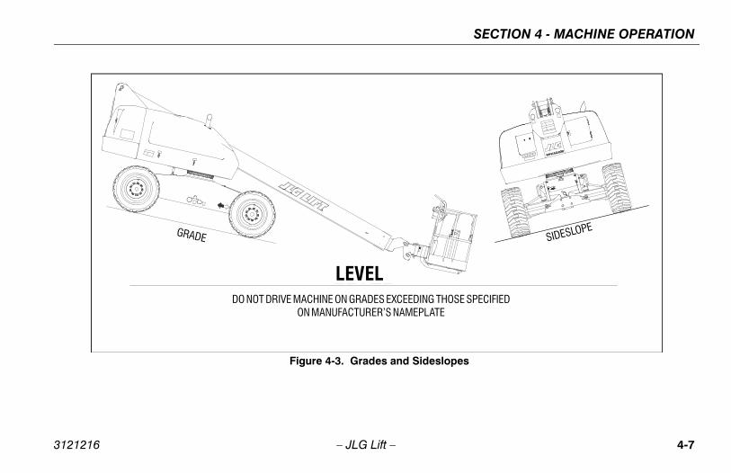
re 4-3., Grades and Sideslopes
RIVE WITH BOOM EXTENDED OR ABOVE HORIZONTAL A SMOOTH, FIRM AND LEVEL SURFACE.
IVE WITH HOODS RAISED OR UNLATCHED.
OSS OF TRAVEL CONTROL OR UPSET ON GRADES ANDS, DO NOT DRIVE MACHINE ON GRADES OR SIDESLOPES THOSE SPECIFIED ON MACHINE INFORMATION PLACARDT SIDE OF THE FRAME.
3121216 – JLG Lift –
6. Turn key of SELECT switch to PLATFORM.
7. From Platform position POWER/EMERGENCY STOP switch to ON, then push the ENGINE START switch to the forward position until engine starts.
NOTE: Footswitch must be in released (up) position beforestarter will operate. If starter operates with footswitchin the depressed position, DO NOT OPERATEMACHINE.
Shutdown Procedure
IF AN ENGINE MALFUNCTION NECESSITATES UNSCHEDULED SHUT-DOWN, DETERMINE AND CORRECT CAUSE BEFORE RESUMING ANYOPERATION.
1. Remove all load and allow engine to operate at low speed setting for 3-5 minutes; this allows for further reduction of internal engine temperature.
2. Position POWER/EMERGENCY STOP switch to OFF.
3. Turn key of MASTER switch to OFF position.
NOTE: Refer to Engine Manufacturer’s manual for detailedinformation.
4.4 TR
See Figu
DO NOT DEXCEPT ON
DO NOT DR
TO AVOID LSIDESLOPEEXCEEDINGON THE LEF

SECTION 4 - MACHINE OPERATION
4-6 3121216
TRATHEREVVATMACDRIVONE
BEFON DRIVARR
is limited by two factors:
ability, which is the percent of grade of the incline achine can climb.
lope, which is the angle of the slope the machine e driven across.
boom is raised or extended, the machine shoulderated on grades or sideslopes that are greateretected by the tilt alarm. The tilt alarm will sounde operator when the machine is on an unsafee machines high drive function will also be cutw drive.
– JLG Lift –
VEL GRADES WITH DRIVE SPEED/TORQUE SELECT SWITCH IN FORWARD POSITION. USE EXTREME CAUTION WHEN DRIVING INERSE AND AT ALL TIMES WHEN DRIVING WITH PLATFORM ELE-ED AND ESPECIALLY WHEN DRIVING WITH ANY PART OFHINE WITHIN 6 FEET (2 M) OF AN OBSTRUCTION. DO NOT USEE TO MANEUVER PLATFORM CLOSE TO AN OBSTRUCTION...USE
OF THE BOOM FUNCTIONS.
ORE DRIVING, LOCATE THE BLACK/WHITE ORIENTATION ARROWSBOTH THE CHASSIS AND THE PLATFORM CONTROLS. MOVE THEE CONTROLS IN A DIRECTION MATCHING THE DIRECTIONAL
OWS.
Traveling
1. Gradethe m
2. Sidescan b
When thenot be opthan that dto alert thslope. Thback to lo
SECTION 4 - MACHINE OPERATION
4-7
lopes
HOSE SPECIFIED E
SIDESLOPE
3121216 – JLG Lift –
Figure 4-3. Grades and Sides
DO NOT DRIVE MACHINE ON GRADES EXCEEDING TON MANUFACTURER’S NAMEPLAT
GRADE
LEVEL

SECTION 4 - MACHINE OPERATION
4-8 3121216
aveling up grades, position switches as follows:on DRIVE SPEED/TORQUE SELECT switch to .
r smoother operation when driving with fullyended boom, place DRIVE control to SLOW beforepping.
ine is equipped with a Drive Orientation Indicator. light on the platform control console indicates
oom is swung beyond the rear drive tires and theay Drive/Steer in the opposite direction from the
t of the controls. If the indicator is illuminated,e Drive function in the following manner:
the black and white direction arrows on both rm control panel and the chassis to determine the ion the machine will travel.
and release the Drive Orientation Override switch. 3 seconds, slowly move the Drive control toward row matching the intended direction of machine . The indicator light will flash during the 3 second al until the drive function is selected.
– JLG Lift –
Traveling Forward or Reverse1. With engine running, depress footswitch and position
DRIVE control to FORWARD and hold for the duration of forward travel desired.
NOTE: When DRIVE or STEER functions are being operatedthere is an interlock which prevents operation ofboom functions.
2. Depress footswitch and position DRIVE control to REVERSE and hold for duration of reverse travel desired.
3. Depress footswitch and position STEER control to RIGHT for traveling right and LEFT for traveling left.
4. To obtain maximum travel speed, position the DRIVE controller to FAST and activate the following switches: Position DRIVE SPEED/TORQUE SELECT switch to FAST. (Forward Position)
5. Prior to stopping the machine, position switches as fol-lows:Position DRIVE SPEED/TORQUE SELECT switch to LOW. (Backward Position)
6. For trPositiHIGH
NOTE: Foextsto
This machThe yellowthat the bmachine mmovemenoperate th
1. Matchplatfodirect
2. PushWithinthe artravelinterv

SECTION 4 - MACHINE OPERATION
4-9
ATFORM
ing from Ground Levelosition chassis on a smooth, firm and level surface.
total load (personnel, tools, and supplies) is less than ated capacity, distribute load uniformly on platform oor, and proceed to work position.
ing From Positions Above Ground Levelore loading weight to platform above ground level:
etermine what the total rated capacity weight will be fter additional weight is loaded (personnel, tools and upplies).
total weight in platform will be less then rated capac-y, proceed with adding weight.
3121216 – JLG Lift –
4.5 STEERINGDepress footswitch to steer machine, push on the left sideof the switch to steer left, on the right side to steer right.
BEFORE OPERATING MACHINE, MAKE SURE BOOM IS POSITIONEDOVER REAR AXLE. IF BOOM IS OVER FRONT AXLE (STEER WHEELS),STEER AND DRIVE CONTROLS WILL MOVE IN OPPOSITE DIRECTIONTHAN INDICATED ON MACHINE PLACARDS.
4.6 PARKING AND STOWINGPark and stow machine as follows:
1. Park machine in travel position; boom lowered over rear, all access panels and doors closed and secured, ignition off.
2. Check that brakes hold machine in position.
3. Chock wheels front and rear.
4. Turn off SELECT switch and remove key.
4.7 PL
Load1. P
2. Ifrfl
LoadBef
1. Das
2. Ifit

SECTION 4 - MACHINE OPERATION
4-1 3121216
Pla
ONLSLIGCAUSO C
G LIGHT IS LOCATED ON THE CONTROL CONSOLEHEN THE CHASSIS IS ON A 5 DEGREE OR GREATER
SWING OR RAISE BOOM ABOVE HORIZONTAL WHEN
ON TILT ALARM AS A LEVEL INDICATOR FOR THEILT ALARM INDICATES THE CHASSIS IS ON A SEVEREE OR GREATER). CHASSIS MUST BE LEVEL BEFOREAISING BOOM ABOVE HORIZONTAL.
INE UPSET IF THE TILT WARNING LIGHT ILLUMI-E BOOM IS RAISED ABOVE HORIZONTAL, LOWER THEROUND LEVEL, THEN REPOSITION MACHINE SO THATEL BEFORE RAISING BOOM.
H BOOM BELOW HORIZONTAL IS PERMITTED ONIDE SLOPES SPECIFIED ON SERIAL NUMBER PLAC-
US INJURY, DO NOT OPERATE MACHINERY IF ANYR OR TOGGLE SWITCH CONTROLLING PLATFORMES NOT RETURN TO THE "OFF" POSITION WHEN
0 – JLG Lift –
tform Level Adjustment
Y USE THE PLATFORM LEVELING OVERRIDE FUNCTION FORHT LEVELING OF THE PLATFORM. INCORRECT USE COULDSE THE LOAD/OCCUPANTS TO SHIFT OR FALL. FAILURE TO DOOULD RESULT IN DEATH OR SERIOUS INJURY.
This switch is used to adjust the platform level in situationssuch as ascending/descending a grade. To Level Up orDown - Position the Platform/Level control switch Up orDown and hold until the platform is level.
Platform Rotation1. Depress footswitch to rotate platform to the left, PLAT-
FORM ROTATE control is positioned to the LEFT and held until desired position is reached.
2. Depress footswitch to rotate platform to the right, PLAT-FORM ROTATE control is positioned to the RIGHT and held until desired position is reached.
4.8 BOOM
A TILT WARNINWHICH LIGHTS WSLOPE. DO NOT LIGHT IS LIT.
DO NOT DEPENDCHASSIS. THE TSLOPE (5 DEGRESWINGING, OR R
TO AVOID MACHNATED WHEN THPLATFORM TO GCHASSIS IS LEV
TRAVELING WITGRADES AND SARD.
TO AVOID SERIOCONTROL LEVEMOVEMENT DORELEASED.
SECTION 4 - MACHINE OPERATION
4-11
coping the Main Boomxtend or retract the main boom, with the footswitch
vated, position the Main Telescope Control Switch toin or out position and hold until the platform reachesdesired position.
3121216 – JLG Lift –
TO AVOID A COLLISION AND INJURY IF PLATFORM DOES NOT STOPWHEN A CONTROL SWITCH OR LEVER IS RELEASED, REMOVE FOOTFROM FOOTSWITCH OR USE EMERGENCY STOP SWITCH TO STOPMACHINE.
Swinging the BoomDepress footswitch to swing boom, with footswitch acti-vated, position SWING control switch to RIGHT or LEFTfor direction desired.
WHEN SWINGING THE BOOM MAKE SURE THERE IS AMPLE ROOMFOR THE BOOM TO CLEAR SURROUNDING WALLS, PARTITIONS ANDEQUIPMENT.
Raising and Lowering the Main Boom
NOTE: Lift up will not function when the boom is near fullelevation and the platform is out of level.
To raise or lower the Main Boom, with footswitch acti-vated, position Main Boom Lift lever to UP or DOWN untildesired height is reached.
TelesTo eactithe the

SECTION 4 - MACHINE OPERATION
4-1 3121216
4.9
WHETHAOVE
on AUXILIARY POWER switch to ON and hold.
se AUXILIARY POWER switch, selected control , lever or controller, and footswitch.
on POWER/EMERGENCY STOP switch to OFF.
g from the Ground Control Stationon PLATFORM/GROUND SELECT KEY SWITCH OUND.
on POWER/EMERGENCY STOP switch to ON.
te appropriate control switch or controller for d function and hold.
on AUXILIARY POWER switch to ON and hold.
se AUXILIARY POWER switch, and appropriate ol switch or controller.
on POWER/EMERGENCY STOP switch to OFF.
2 – JLG Lift –
AUXILIARY POWER - NON ADE EQUIPPED MACHINES
N OPERATING ON AUXILIARY POWER, DO NOT OPERATE MOREN ONE FUNCTION AT A TIME. (SIMULTANEOUS OPERATION CANRLOAD THE 12-VOLT AUXILIARY PUMP MOTOR.)
A toggle type auxiliary power control switch is located onthe platform control station and another is located on theground control station. Operation of either switch turns onthe electrically driven auxiliary hydraulic pump. Thisshould be used in case of failure of the main power plant.The auxiliary pump will operate boom lift, telescope andswing. To activate auxiliary power:
Activating from the Platform Control Station1. Position PLATFORM/GROUND SELECT KEY SWITCH
to PLATFORM.
2. Position POWER/EMERGENCY STOP switch to ON.
3. Depress and hold footswitch.
4. Operate appropriate control switch, lever or controller for desired function and hold.
5. Positi
6. Releaswitch
7. Positi
Activatin1. Positi
to GR
2. Positi
3. Operadesire
4. Positi
5. Releacontr
6. Positi
SECTION 4 - MACHINE OPERATION
4-13
perate appropriate control switch, lever or controller r desired function and hold.
elease AUXILIARY POWER switch, selected control witch, lever or controller, and footswitch.
osition POWER/EMERGENCY STOP switch to OFF.
ating from the Ground Control Stationosition PLATFORM/GROUND SELECT KEY SWITCH
o GROUND.
osition POWER/EMERGENCY STOP switch to ON.
osition AUXILIARY POWER switch to ON and hold.
perate appropriate control switch or controller for esired function and hold.
elease AUXILIARY POWER switch, and appropriate ontrol switch or controller.
osition POWER/EMERGENCY STOP switch to OFF.
3121216 – JLG Lift –
4.10 AUXILIARY POWER - ADE EQUIPPED MACHINES
WHEN OPERATING ON AUXILIARY POWER, DO NOT OPERATE MORETHAN ONE FUNCTION AT A TIME. (SIMULTANEOUS OPERATION CANOVERLOAD THE 12-VOLT AUXILIARY PUMP MOTOR.)
A toggle type auxiliary power control switch is located onthe platform control station and another is located on theground control station. Operation of either switch turns onthe electrically driven auxiliary hydraulic pump. Thisshould be used in case of failure of the main power plant.The auxiliary pump will operate boom lift, telescope andswing. To activate auxiliary power:
Activating from the Platform Control Station1. Position PLATFORM/GROUND SELECT KEY SWITCH
to PLATFORM.
2. Position POWER/EMERGENCY STOP switch to ON.
3. Depress and hold footswitch.
4. Position AUXILIARY POWER switch to ON and hold.
5. Ofo
6. Rs
7. P
Activ1. P
t
2. P
3. P
4. Od
5. Rc
6. P

SECTION 4 - MACHINE OPERATION
4-1 3121216
4.1 OWN AND LIFTINGght of the machine is stamped on the serial num-. If the plate is missing or illegible, call JLG Indus-weigh the individual unit to find out the GrossWeight.
ansporting machine, boom must be in the stowednd machine securely tied down to truck or trailerur tie down eyes are provided in the frame slab,ach corner of the machine. Lock turntable before long distances or before hauling machine on atrailer.
mes necessary to lift the machine using an over- mobile crane, it is very important that the lifting are attached only to the designated lifting area.ure 4-6 Lifting and Tie Down Decal)
down eyes are provided at the front, center, andr in the frame slab. Lifting eyes are located in plateunted on machine front at boom pivot. (See Figure Lifting and Tie Down Decal)
4 – JLG Lift –
1 SHUT DOWN AND PARK1. Drive machine to a protected area.
2. Assure main boom is fully retracted and lowered over rear (Drive) axle; all access panels and doors closed and secured.
3. Remove all load and allow engine to operate 3-5 min-utes at LOW setting to permit reduction of engine inter-nal temperatures.
4. At Ground Controls, turn KEY SELECT switch to (cen-ter) OFF. Position, POWER/EMERGENCY STOP switch (down) to OFF. Remove key.
5. Cover Platform Control console to protect instruction placards, warning decals and operating controls from hostile environment.
4.12 TIE DThe weiber platetries or Vehicle
When trmode adeck. Foone at etravelingtruck or
If it becohead ordevices(See Fig
NOTE: Tiereamo4-6

SECTION 4 - MACHINE OPERATION
4-15
odels
NOTE: When transporting machine over roughterrain or long distance, the boomneeds to be chocked and strappedwhenever the base boom is unable torest on its pad. This prevents the boomfrom bouncing up and down and pre-venting possible damage while trans-porting.
3121216 – JLG Lift –
Figure 4-4. Machine Tie Down - 400S M
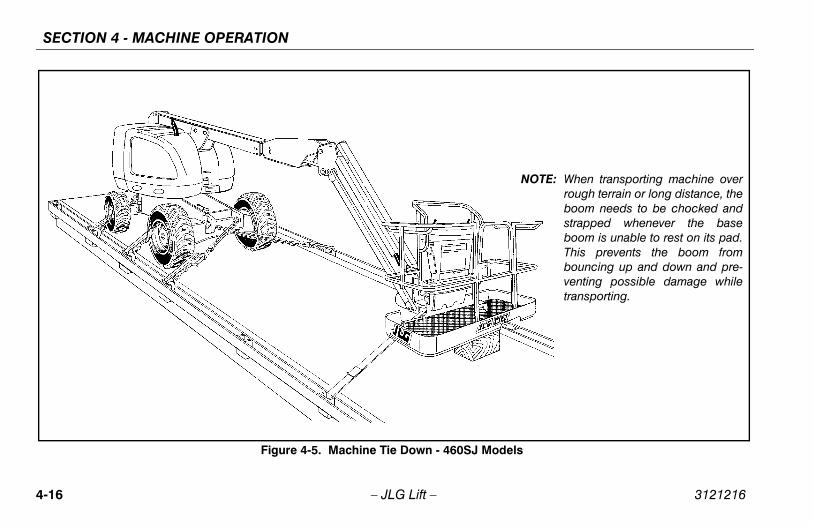
SECTION 4 - MACHINE OPERATION
4-1 3121216
odels
NOTE: When transporting machine overrough terrain or long distance, theboom needs to be chocked andstrapped whenever the baseboom is unable to rest on its pad.This prevents the boom frombouncing up and down and pre-venting possible damage whiletransporting.
6 – JLG Lift –
Figure 4-5. Machine Tie Down - 460SJ M

SECTION 4 - MACHINE OPERATION
4-17
own
3121216 – JLG Lift –
Figure 4-6. Lifting and Tie D
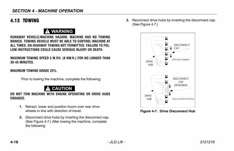
SECTION 4 - MACHINE OPERATION
4-1 3121216
4.1
RUNBRAALLLOW
MAX30-4
MAX
DO ENG
nnect drive hubs by inverting the disconnect cap. Figure 4-7.)
Figure 4-7. Drive Disconnect Hub
8 – JLG Lift –
3 TOWING
AWAY VEHICLE/MACHINE HAZARD. MACHINE HAS NO TOWINGKES. TOWING VEHICLE MUST BE ABLE TO CONTROL MACHINE AT TIMES. ON-HIGHWAY TOWING NOT PERMITTED. FAILURE TO FOL- INSTRUCTIONS COULD CAUSE SERIOUS INJURY OR DEATH.
IMUM TOWING SPEED 5 M.P.H. (8 KM/H.) FOR NO LONGER THAN5 MINUTES.
IMUM TOWING GRADE 25%.
Prior to towing the machine, complete the following:
NOT TOW MACHINE WITH ENGINE OPERATING OR DRIVE HUBSAGED.
1. Retract, lower and position boom over rear drive wheels in line with direction of travel.
2. Disconnect drive hubs by inverting the disconnect cap. (See Figure 4-7.) After towing the machine, complete the following:
3. Reco(See
SECTION 4 - MACHINE OPERATION
4-19
als are made with a Pressure Sensitive Adhesive onback with a protective film on the front. Remove theaged decal and thoroughly clean surface before
alling a new decal. Simply peel off the back, and press decal onto surface and remove the protective film.
: Placards and Decals can be ordered by using partnumbers located by each placard or decal.
3121216 – JLG Lift –
4.14 PLACARDS AND DECALSRead and understand all placards and decals. Do notoperate any machine on which DANGER, WARNING,CAUTION OR INSTRUCTION PLACARDS OR DECALSARE MISSING OR ILLEGIBLE. Replace placards anddecals if damaged, missing or illegible.
Decthe daminstnew
NOTE

SECTION 4 - MACHINE OPERATION
4-2 3121216
1 of 4
0 – JLG Lift –
Figure 4-8. Decal Installation - Sheet

SECTION 4 - MACHINE OPERATION
4-21
2 of 4
3121216 – JLG Lift –
Figure 4-9. Decal Installation - Sheet

SECTION 4 - MACHINE OPERATION
4-2 3121216
3 of 4
2 – JLG Lift –
Figure 4-10. Decal Installation - Sheet

SECTION 4 - MACHINE OPERATION
4-23
et 4 of 4
3121216 – JLG Lift –
Figure 4-11. Decal Installation - She
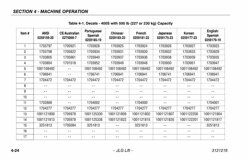
SECTION 4 - MACHINE OPERATION
4-2 3121216
kg) Capacity
Japanese0259175-23
Korean0259177-23
English/Spanish
0259179-19
1703926 1703927 1703923
1703932 1703933 1703929
1703938 1703939 1703935
1703950 1703951 1703947
1001108492 1001108492 1001108492
1706741 1706941 1706941
1704472 1704472 1704472
- - - - - -
- - - - - -
- - - - - -
- - - - 1704001
1704277 1704277 1704277
1001121807 1001122200 1001121804
1001121820 1001122201 1001121817
- - - - 3251813
- - - - - -
- - - - - -
4 – JLG Lift –
Table 4-1. Decals - 400S with 500 lb (227 or 230
Item # ANSI0259159-20
CE/Australian0275066-7
Portuguese/Spanish
0259185-19
Chinese/0259183-23
French0259181-22
1 1703797 1705921 1703928 1703925 1703924
2 1703798 1705822 1703934 1703931 1703930
3 1703805 1705961 1703940 1703937 1703936
4 1703804 1701518 1703952 1703949 1703948
5 1001108492 - - 1001108492 1001108492 1001108492
6 1706941 - - 1706741 1706941 1706941
7 1704472 1704472 1704472 1704472 1704472
8 - - - - - - - - - -
9 - - - - - - - - - -
10 - - - - - - - - - -
11 1702868 - - 1704002 - - 1704000
12 1704277 1704277 1704277 1704277 1704277
13 1001121800 1705978 1001125330 1001121809 1001121802
14 1001121813 1705978 1001125338 1001121822 1001121815
15 3251813 1705084 3251813 - - 3251813
16 - - - - - - - - - -
17 - - - - - - - - - -

SECTION 4 - MACHINE OPERATION
4-25
504 1701504 1701504 1701504
006 - - - - 1704007
631 1702631 1702631 1702631
584 1700584 1700584 1700584
- - - - - - -
509 1701509 1701509 1701509
300 1702300 1702300 1702300
500 1701500 1701500 1701500
529 1701529 1701529 1701529
- - - - - - -
- - - - - - -
- - - - - - -
- - - - - - -
- - - - - - -
- - - - - - -
- - - - - - -
984 1703980 1703981 1703983
126 1706126 1706126 - -
230 kg) Capacity
ch81-22
Japanese0259175-23
Korean0259177-23
English/Spanish
0259179-19
3121216 – JLG Lift –
18 1701504 1701504 1701504 1701504 1701
19 - - - - 1704008 - - 1704
20 1702631 1702631 1702631 1702631 1702
21 1700584 1700584 1700584 1700584 1700
22 - - - - - - - - -
23 1701509 1701509 1701509 1701509 1701
24 1702300 1702300 1702300 1702300 1702
25 1701500 1701500 1701500 1701500 1701
26 1701529 1701529 1701529 1701529 1701
27 - - - - - - - - -
28 - - - - - - - - -
29 - - - - - - - - -
30 - - - - - - - - -
31 - - - - - - - - -
32 - - - - - - - - -
33 - - - - - - - - -
34 - - 1705828 1703985 1703982 1703
35 1706126 1706126 - - 1706126 1706
Table 4-1. Decals - 400S with 500 lb (227 or
Item # ANSI0259159-20
CE/Australian0275066-7
Portuguese/Spanish
0259185-19
Chinese/0259183-23
Fren02591

SECTION 4 - MACHINE OPERATION
4-2 3121216
- - - - - -
- - - - - -
- - - - - -
- - - - - -
- - - - - -
- - - - - -
- - N/A - -
- - N/A - -
- - N/A - -
1701499 1701499 1701499
3252680 3252681 3252682
1704412 1704412 1704412
- - - - - -
1701691 1701691 1701691
1704726 1704726 1704726
- - - - - -
- - - - - -
kg) Capacity
Japanese0259175-23
Korean0259177-23
English/Spanish
0259179-19
6 – JLG Lift –
36 - - - - - - - - - -
37 - - - - - - - - - -
38 - - - - - - - - - -
39 - - - - - - - - 1705514
40 - - - - - - - - - -
41 - - - - - - - - - -
42 - - - - - - - - - -
43 - - - - - - - - - -
44 - - - - - - - - - -
45 1701499 1701499 1701499 1701499 1701499
46 3252672 1707031 3252685 3252684 3252683
47 1704412 1704412 1704412 1704412 1704412
48 - - - - - - - - - -
49 1701691 1701691 1701691 1701691 1701691
50 1704726 1704726 1704726 1704726 1704726
51 - - - - - - - - - -
52 - - - - - - - - - -
Table 4-1. Decals - 400S with 500 lb (227 or 230
Item # ANSI0259159-20
CE/Australian0275066-7
Portuguese/Spanish
0259185-19
Chinese/0259183-23
French0259181-22
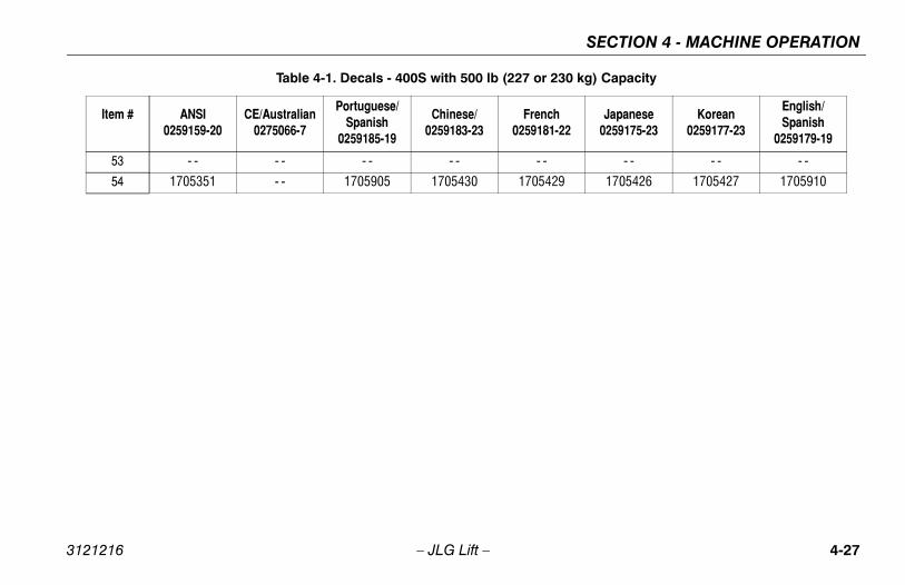
SECTION 4 - MACHINE OPERATION
4-27
- - - - - - -
429 1705426 1705427 1705910
230 kg) Capacity
ch81-22
Japanese0259175-23
Korean0259177-23
English/Spanish
0259179-19
3121216 – JLG Lift –
53 - - - - - - - - -
54 1705351 - - 1705905 1705430 1705
Table 4-1. Decals - 400S with 500 lb (227 or
Item # ANSI0259159-20
CE/Australian0275066-7
Portuguese/Spanish
0259185-19
Chinese/0259183-23
Fren02591

SECTION 4 - MACHINE OPERATION
4-2 3121216
) Capacity
Japanese0259989-20
Korean0259990-20
English/Spanish
0259991-17
1703926 1703927 1703923
1703932 1703933 1703929
1703938 1703939 1703935
1703950 1703951 1703947
1001108492 1001108492 1001108492
1706941 1706941 1706941
1704472 1704472 1704472
- - - - - -
- - - - - -
- - - - - -
- - - - 1704001
1704277 1704277 1704277
1001125323 1001125324 1001125325
1001125332 1001125333 1001125334
- - - - 3251813
- - - - 1701502
- - - - 1701503
8 – JLG Lift –
Table 4-2. Decals - 400S with 750 lb (340 kg
Item # ANSI0259981-17
CE/Australian0275068-6
Portuguese/Spanish
0259994-17
Chinese0259993-20
French0259992-20
1 1703797 1705921 1703928 1703925 1703924
2 1703798 1705822 1703934 1703931 1703930
3 1703805 1705961 1703940 1703937 1703936
4 1703804 1701518 1703952 1703949 1703948
5 1001108492 - - 1001108492 1001108492 1001108492
6 1706941 - - 1706941 1706741 1706741
7 1704472 1704472 1704472 1704472 1704472
8 - - - - - - - - - -
9 - - - - - - - - - -
10 - - - - - - - - - -
11 1702868 - - 1704002 - - 1704000
12 1704277 1704277 1704277 1704277 1704277
13 1001125322 1706382 1001125329 1001125328 1001125327
14 1001125331 1706382 1001125337 1001125336 1001125335
15 3251813 1705084 3251813 - - 3251813
16 - - - - - - 1701502 - -
17 - - - - - - 1701503 - -

SECTION 4 - MACHINE OPERATION
4-29
504 1701504 1701504 1701504
006 - - - - 1704007
631 1702631 1702631 1702631
584 1700584 1700584 1700584
- N/A - - - -
509 1701509 1701509 1701509
300 1702300 1702300 1702300
500 1701500 1701500 1701500
529 1701529 1701529 1701529
- - - - - - -
- - - - - - -
- - - - - - -
- - - - - - -
- - - - - - -
- - - - - - -
- - - - - - -
984 1703980 1703981 1703983
829 1704829 1704829 - -
0 kg) Capacity
ch92-20
Japanese0259989-20
Korean0259990-20
English/Spanish
0259991-17
3121216 – JLG Lift –
18 1701504 1701504 1701504 1701504 1701
19 - - - - 1704008 - - 1704
20 1702631 1702631 1702631 1702631 1702
21 1700584 1700584 1700584 1700584 1700
22 - - - - - - - - -
23 1701509 1701509 1701509 1701509 1701
24 1702300 1702300 1702300 1702300 1702
25 1701500 1701500 1701500 1701500 1701
26 1701529 1701529 1701529 1701529 1701
27 - - - - - - - - -
28 - - - - - - - - -
29 - - - - - - - - -
30 - - - - - - - - -
31 - - - - - - - - -
32 - - - - - - - - -
33 - - - - - - - - -
34 - - 1705828 1703985 1703982 1703
35 1704829 1704829 - - 1704829 1704
Table 4-2. Decals - 400S with 750 lb (34
Item # ANSI0259981-17
CE/Australian0275068-6
Portuguese/Spanish
0259994-17
Chinese0259993-20
Fren02599

SECTION 4 - MACHINE OPERATION
4-3 3121216
- - - - - -
- - - - - -
- - - - - -
- - - - - -
- - - - - -
- - - - - -
- - - - - -
- - - - - -
- - - - - -
1701499 1701499 1701499
3252680 3252681 3252682
1704412 1704412 1704412
- - - - - -
1701691 1701691 1701691
1704726 1704726 1704726
- - - - - -
- - - - - -
) Capacity
Japanese0259989-20
Korean0259990-20
English/Spanish
0259991-17
0 – JLG Lift –
36 - - - - - - - - - -
37 - - - - - - - - - -
38 - - - - - - - - - -
39 - - - - - - - - 1705514
40 - - - - - - - - - -
41 - - - - - - - - - -
42 - - - - - - - - - -
43 - - - - - - - - - -
44 - - - - - - - - - -
45 1701499 1701499 1701499 1701499 1701499
46 3252672 1707031 3252685 3252684 3252683
47 1704412 1704412 1704412 1704412 1704412
48 - - - - - - - - - -
49 1701691 1701691 1701691 1701691 1701691
50 1704726 1704726 1704726 1704726 1704726
51 - - - - - - - - - -
52 - - - - - - - - - -
Table 4-2. Decals - 400S with 750 lb (340 kg
Item # ANSI0259981-17
CE/Australian0275068-6
Portuguese/Spanish
0259994-17
Chinese0259993-20
French0259992-20
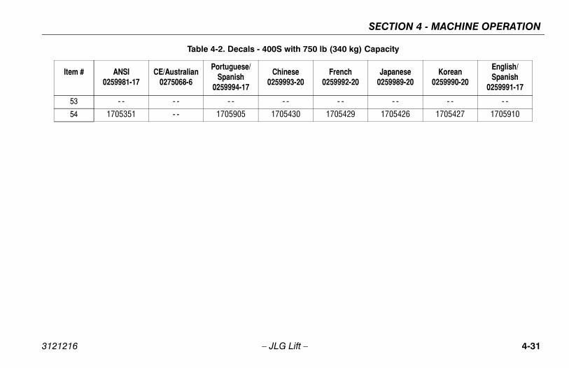
SECTION 4 - MACHINE OPERATION
4-31
- - - - - - -
429 1705426 1705427 1705910
0 kg) Capacity
ch92-20
Japanese0259989-20
Korean0259990-20
English/Spanish
0259991-17
3121216 – JLG Lift –
53 - - - - - - - - -
54 1705351 - - 1705905 1705430 1705
Table 4-2. Decals - 400S with 750 lb (34
Item # ANSI0259981-17
CE/Australian0275068-6
Portuguese/Spanish
0259994-17
Chinese0259993-20
Fren02599

SECTION 4 - MACHINE OPERATION
4-3 3121216
Japanese0259176-21
Korean0259178-20
English/Spanish
0259180-18
1703926 1703927 1703923
1703932 1703933 1703929
1703938 1703939 1703935
1703950 1703951 1703947
1001108492 1001108492 1001108492
1706941 1706941 1706941
1704473 1704473 1704473
- - - - - -
- - - - - -
- - - - - -
- - - - 1704001
1704277 1704277 1704277
1001121808 1001121918 1001121801
1001121821 1001121921 1001121814
- - - - 3251813
- - - - - -
- - - - - -
2 – JLG Lift –
Table 4-3. Decals - 460SJ
Item # ANSI0259160-16
CE/Australian1001114405-1
Portuguese/Spanish
0259186-19
Chinese0259184-22
French0259182-21
1 1703797 1705921 1703928 1703925 1703924
2 1703798 1705822 1703934 1703931 1703930
3 1703805 1705961 1703940 1703937 1703936
4 1703804 1701518 1703952 1703949 1703948
5 1706708 - - 1706941 1001108492 1001108492
6 1706941 - - 1706709 1706941 1706941
7 1704473 1704473 1704473 1704473 1704473
8 - - - - - - - - - -
9 - - - - - - - - - -
10 - - - - - - - - - -
11 1702868 - - 1704002 - - 1704000
12 1704277 1704277 1704277 1704277 1704277
13 1001121801 1705978 1001121920 1001121812 1001121803
14 1001121814 1705978 1001121923 1001121825 1001121816
15 3251813 1705084 3251813 - - 3251813
16 - - - - - - - - - -
17 - - - - - - - - - -

SECTION 4 - MACHINE OPERATION
4-33
504 1701504 1701504 1701504
006 - - - - 1704007
631 1702631 1702631 1702631
584 1700584 1700584 1700584
- - - - - - -
509 1701509 1701509 1701509
300 1702300 1702300 1702300
500 1701500 1701500 1701500
529 1701529 1701529 1701529
- - - - - - -
- - - - - - -
- - - - - - -
- - - - - - -
- - - - - - -
- - - - - - -
- - - - - - -
984 1703980 1703981 1703983
828 1704828 1704828 - -
ch82-21
Japanese0259176-21
Korean0259178-20
English/Spanish
0259180-18
3121216 – JLG Lift –
18 1701504 1701504 1701504 1701504 1701
19 - - - - 1704008 - - 1704
20 1702631 1702631 1702631 1702631 1702
21 1700584 1700584 1700584 1700584 1700
22 - - - - - - - - -
23 1701509 1701509 1701509 1701509 1701
24 1702300 1702300 1702300 1702300 1702
25 1701500 1701500 1701500 1701500 1701
26 1701529 1701529 1701529 1701529 1701
27 - - - - - - - - -
28 - - - - - - - - -
29 - - - - - - - - -
30 - - - - - - - - -
31 - - - - - - - - -
32 - - - - - - - - -
33 - - - - - - - - -
34 - - 1705828 1703985 1703982 1703
35 1704828 1704828 - - 1704828 1704
Table 4-3. Decals - 460SJ
Item # ANSI0259160-16
CE/Australian1001114405-1
Portuguese/Spanish
0259186-19
Chinese0259184-22
Fren02591
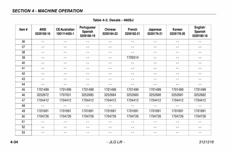
SECTION 4 - MACHINE OPERATION
4-3 3121216
- - - - - -
- - - - - -
- - - - - -
- - - - - -
- - - - - -
- - - - - -
- - - - - -
- - - - - -
- - - - - -
1701499 1701499 1701499
3252680 3252681 3252682
1704412 1704412 1704412
- - - - - -
1701691 1701691 1701691
1704726 1704726 1704726
- - - - - -
- - - - - -
- - - - - -
Japanese0259176-21
Korean0259178-20
English/Spanish
0259180-18
4 – JLG Lift –
36 - - - - - - - - - -
37 - - - - - - - - - -
38 - - - - - - - - - -
39 - - - - - - - - 1705514
40 - - - - - - - - - -
41 - - - - - - - - - -
42 - - - - - - - - - -
43 - - - - - - - - - -
44 - - - - - - - - - -
45 1701499 1701499 1701499 1701499 1701499
46 3252672 1707031 3252685 3252684 3252683
47 1704412 1704412 1704412 1704412 1704412
48 - - - - - - - - - -
49 1701691 1701691 1701691 1701691 1701691
50 1704726 1704726 1704726 1704726 1704726
51 - - - - - - - - - -
52 - - - - - - - - - -
53 - - - - - - - - - -
Table 4-3. Decals - 460SJ
Item # ANSI0259160-16
CE/Australian1001114405-1
Portuguese/Spanish
0259186-19
Chinese0259184-22
French0259182-21

SECTION 4 - MACHINE OPERATION
4-35
429 1705426 1702427 1705910
- - - - - - -
ch82-21
Japanese0259176-21
Korean0259178-20
English/Spanish
0259180-18
3121216 – JLG Lift –
54 1705351 - - 1705905 1705430 1705
55 - - 1001112551 - - - - -
Table 4-3. Decals - 460SJ
Item # ANSI0259160-16
CE/Australian1001114405-1
Portuguese/Spanish
0259186-19
Chinese0259184-22
Fren02591
SECTION 4 - MACHINE OPERATION
4-3 3121216
6 – JLG Lift –NOTES:
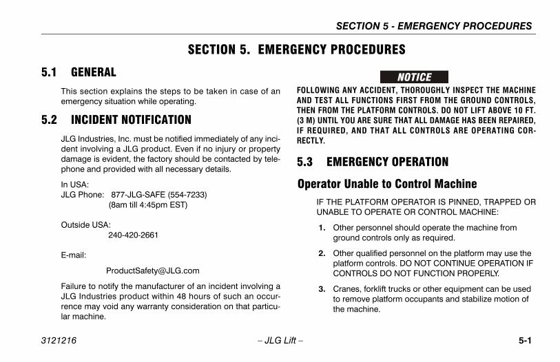
SECTION 5 - EMERGENCY PROCEDURES
5-1
ROCEDURES
ANY ACCIDENT, THOROUGHLY INSPECT THE MACHINEALL FUNCTIONS FIRST FROM THE GROUND CONTROLS, THE PLATFORM CONTROLS. DO NOT LIFT ABOVE 10 FT. YOU ARE SURE THAT ALL DAMAGE HAS BEEN REPAIRED,
ED, AND THAT ALL CONTROLS ARE OPERATING COR-
ERGENCY OPERATION
r Unable to Control MachineE PLATFORM OPERATOR IS PINNED, TRAPPED ORLE TO OPERATE OR CONTROL MACHINE:
ther personnel should operate the machine from round controls only as required.
ther qualified personnel on the platform may use the latform controls. DO NOT CONTINUE OPERATION IF ONTROLS DO NOT FUNCTION PROPERLY.
ranes, forklift trucks or other equipment can be used o remove platform occupants and stabilize motion of he machine.
3121216 – JLG Lift –
SECTION 5. EMERGENCY P
5.1 GENERALThis section explains the steps to be taken in case of anemergency situation while operating.
5.2 INCIDENT NOTIFICATIONJLG Industries, Inc. must be notified immediately of any inci-dent involving a JLG product. Even if no injury or propertydamage is evident, the factory should be contacted by tele-phone and provided with all necessary details.
In USA:JLG Phone: 877-JLG-SAFE (554-7233) (8am till 4:45pm EST)
Outside USA: 240-420-2661
E-mail:
Failure to notify the manufacturer of an incident involving aJLG Industries product within 48 hours of such an occur-rence may void any warranty consideration on that particu-lar machine.
FOLLOWINGAND TEST THEN FROM(3 M) UNTILIF REQUIRRECTLY.
5.3 EM
OperatoIF THUNAB
1. Og
2. OpC
3. Ctt
SECTION 5 - EMERGENCY PROCEDURES
5-2 3121216
Pla GENCY TOWING PROCEDUREShis machine is prohibited, unless properly. However, provisions for moving the machine
n incorporated. For specific procedures, refer to
– JLG Lift –
tform or Boom Caught OverheadIf the platform or boom becomes jammed or snagged inoverhead structures or equipment, rescue platform occu-pants prior to freeing the machine.
5.4 EMERTowing tequippedhave beeSection 4.

FICATIONS & OPERATOR MAINTENANCE
6-1
OPERATOR MAINTENANCE
ERATING SPECIFICATIONS
1. Operating Specifications - 400S - Prior to S/N 0300142870
rk Load (Capacity):d:
standard 500 lbs. (230 kg.)1000 lbs. (450 kg)750 lbs. (340 kg)
vel Grade, Stowed Position see Figure 4-3.
2 W/D-30% 4 W/D-45%
vel Grade, Stowed Positionsee Figure 4-3.
5o
rtical Platform Height: 40 ft. (12 m)
rizontal Platform Reach: 34 ft. (10 m.)
s (Outside) 16 ft. (5 m.)
s (Inside) 6 ft.-8 in. (2 m.)
6ft.- 6in. (1.98 m)
Zero
t 7ft. 4in. (2.24 m)
SECTION 6 - GENERAL SPECI
3121216 – JLG Lift –
SECTION 6. GENERAL SPECIFICATIONS &
6.1 INTRODUCTIONThis section of the manual provides additional necessaryinformation to the operator for proper operation and mainte-nance of this machine.
The maintenance portion of this section is intended as infor-mation to assist the machine operator to perform daily main-tenance tasks only, and does not replace the more thoroughPreventive Maintenance and Inspection Schedule includedin the Service and Maintenance Manual.
Other Publications Available:
Service and Maintenance Manual (ANSI, CSA) ....... 3120788
Service and Maintenance Manual (CE, AUS)........... 3120895
Illustrated Parts Manual (ANSI, CSA)Prior to S/N 96000.................................................. 3120789
Illustrated Parts Manual (CE, AUS)Prior to S/N 96000.................................................. 3120896
Illustrated Parts Manual (Global)S/N 96000 to Present............................................. 3121236
6.2 OP
Table 6-
Maximum Wo Unrestricte Restricted: Optional:
Maximum Tra(Gradeability)
Maximum Tra (Side Slope)
Maximum Ve
Maximum Ho
Turning Radiu
Turning Radiu
Overall Width
Tail swing
Stowed Heigh

SECTION 6 - GENERAL SPECIFICATIONS & OPERATOR MAINTENANCE
6-2 3121216
Stow
Whe
Gro
MaxMax
Gro 12 14
Trav
Trav
Gro(Pla 5 7
Max
Max
Man
Max
ting Specifications - 400S - S/N 0300142870 to Present
ad (Capacity) - ANSI standard 500 lbs. (227 kg.)1000 lbs. (454 kg)750 lbs. (340 kg)
ad (Capacity) - CE & standard
500 lbs. (230 kg.)1000 lbs. (450 kg)750 lbs. (340 kg)
rade, Stowed Position igure 4-3.
2 W/D-30% 4 W/D-45%
rade, Stowed Positiongure 4-3.
5o
Platform Height: 40 ft. (12 m)
al Platform Reach: 34 ft. (10 m.)
tside) 16 ft. (5 m.)
ide) 6 ft.-8 in. (2 m.)
6ft.- 6in. (1.98 m)
Zero
7ft. 4in. (2.24 m)
– JLG Lift –
ed Length 20ft. 2in. (6.15 m)
elbase 7ft. 10in. (2,3 m)
und Clearance 12in. (30 cm)
. Tire Load (400S-500 lbs. Cap.)
. Tire Load (400S-750 lbs. Cap.)6200 lbs. (2812 kg)8350 lbs. (3788 kg)
und Bearing Pressurex16.5 FF Tiresx17.5 pneumatic tires
58 psi (4.07 kg/cm2)45 psi (3.16 kg/cm2)
el Speed, boom stowed.(2WD/4WD) 4.5 m.p.h. (7.24 kmh) (27-32 sec/ 200ft.)
el Speed, boom elevated. (2WD/4WD) 0.75 m.p.h. (1.20 kmh) (46-115 sec/ 50 ft.)
ss Machine Weight Std. 2wd Machine tform Empty, Pneumatic Tires)00 lb. (230 kg) Capacity50 lb. (340 kg) Capacity
12,525 lbs. (5681kg)13,525 lbs. (6135 kg)
imum System Voltage 12 VDC
. Hydraulic System Operating Pressure 4060 psi (280 bar)
ual Force 400 N maximum
imum Wind Speed 28 mph (12.5 m/s)
Table 6-1. Operating Specifications - 400S - Prior to S/N 0300142870
Table 6-2. Opera
Maximum Work Lo Unrestricted: Restricted: Optional:
Maximum Work Lo Australia Unrestricted: Restricted: Optional:
Maximum Travel G(Gradeability) see F
Maximum Travel G (Side Slope) see Fi
Maximum Vertical
Maximum Horizont
Turning Radius (Ou
Turning Radius (Ins
Overall Width
Tail swing
Stowed Height

FICATIONS & OPERATOR MAINTENANCE
6-3
. Operating Specifications - 460SJ - Prior to S/N 0300142870
rk Load (Capacity):ricted: 500 lbs. (230 kg.)
vel Grade, Stowed Position see Figure 4-3.
2 W/D - 30% 4 W/D - 45%
vel Grade, Stowed Positionsee Figure 4-3.
5o
rtical Platform Height: 46 ft. (14 m.)
rizontal Platform Reach: 40 ft. (12 m.)
s (Outside) 16 ft. (5 m.)
s (Inside) 6 ft.-8 in. (2 m.)
6ft.- 6in. (1.98 m)
zero
t 7ft. 4in. (2.24 m)
th 20ft. 2in. (6.15 m)
7ft. 10in. (2,3 m)
ance 12in. (30 cm)
d 7200 lbs. (3266 kg)
ng Pressure 63 psi (4.4 kg/cm2)
SECTION 6 - GENERAL SPECI
3121216 – JLG Lift –
Stowed Length 20ft. 2in. (6.15 m)
Wheelbase 7ft. 10in. (2,3 m)
Ground Clearance 12in. (30 cm)
Max. Tire Load (400S-500 lbs. Cap.)Max. Tire Load (400S-750 lbs. Cap.)
6200 lbs. (2812 kg)8350 lbs. (3788 kg)
Ground Bearing Pressure 12x16.5 FF Tires 14x17.5 pneumatic tires
58 psi (4.07 kg/cm2)45 psi (3.16 kg/cm2)
Travel Speed, boom stowed.(2WD/4WD) 4.5 m.p.h. (7.24 kmh) (27-32 sec/ 200ft.)
Travel Speed, boom elevated. (2WD/4WD) 0.75 m.p.h. (1.20 kmh) (46-115 sec/ 50 ft.)
Gross Machine Weight Std. 2wd Machine (Platform Empty, Pneumatic Tires) 500 lb. (227 or 230 kg) Capacity 750 lb. (340 kg) Capacity
12,525 lbs. (5681kg)13,525 lbs. (6135 kg)
Maximum System Voltage 12 VDC
Max. Hydraulic System Operating Pressure 4060 psi (280 bar)
Manual Force 400 N maximum
Maximum Wind Speed 28 mph (12.5 m/s)
Table 6-2. Operating Specifications - 400S - S/N 0300142870 to Present
Table 6-3
Maximum Wo Unrest
Maximum Tra(Gradeability)
Maximum Tra (Side Slope)
Maximum Ve
Maximum Ho
Turning Radiu
Turning Radiu
Overall Width
Tail swing
Stowed Heigh
Stowed Leng
Wheelbase
Ground Clear
Max. Tire Loa
Ground Beari
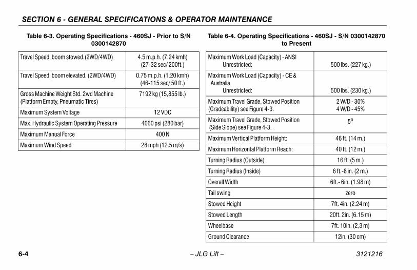
SECTION 6 - GENERAL SPECIFICATIONS & OPERATOR MAINTENANCE
6-4 3121216
Trav
Trav
Gro(Pla
Max
Max
Max
Max
T ating Specifications - 460SJ - S/N 0300142870 to Present
ad (Capacity) - ANSI: 500 lbs. (227 kg.)
ad (Capacity) - CE &
: 500 lbs. (230 kg.)
rade, Stowed Position igure 4-3.
2 W/D - 30% 4 W/D - 45%
rade, Stowed Positiongure 4-3.
5o
Platform Height: 46 ft. (14 m.)
tal Platform Reach: 40 ft. (12 m.)
tside) 16 ft. (5 m.)
ide) 6 ft.-8 in. (2 m.)
6ft.- 6in. (1.98 m)
zero
7ft. 4in. (2.24 m)
20ft. 2in. (6.15 m)
7ft. 10in. (2,3 m)
12in. (30 cm)
– JLG Lift –
el Speed, boom stowed.(2WD/4WD) 4.5 m.p.h. (7.24 kmh)(27-32 sec/ 200ft.)
el Speed, boom elevated. (2WD/4WD) 0.75 m.p.h. (1.20 kmh) (46-115 sec/ 50 ft.)
ss Machine Weight Std. 2wd Machine tform Empty, Pneumatic Tires)
7192 kg (15,855 lb.)
imum System Voltage 12 VDC
. Hydraulic System Operating Pressure 4060 psi (280 bar)
imum Manual Force 400 N
imum Wind Speed 28 mph (12.5 m/s)
able 6-3. Operating Specifications - 460SJ - Prior to S/N 0300142870
Table 6-4. Oper
Maximum Work Lo Unrestricted
Maximum Work Lo Australia Unrestricted
Maximum Travel G(Gradeability) see F
Maximum Travel G (Side Slope) see Fi
Maximum Vertical
Maximum Horizon
Turning Radius (Ou
Turning Radius (Ins
Overall Width
Tail swing
Stowed Height
Stowed Length
Wheelbase
Ground Clearance

FICATIONS & OPERATOR MAINTENANCE
6-5
esTable 6-5. Capacities
26 gallons (98.4 liters)
Tank 40.0 gallons (152 liters)
System (Including Tank) 52 gallons (196.8 liters)
17 ounces (0.5 liters)
l Capacity
llar
4.5 Quarts (4.25 L) w/Filter6.3 qts. (6 L) w/Filter
3.8 quarts (3.6 L) crankcase only4.5 qts. (4.25 L) w/Filter
SECTION 6 - GENERAL SPECI
3121216 – JLG Lift –
Capaciti
Max. Tire Load 7200 lbs. (3266 kg)
Ground Bearing Pressure 63 psi (4.4 kg/cm2)
Travel Speed, boom stowed.(2WD/4WD) 4.5 m.p.h. (7.24 kmh)(27-32 sec/ 200ft.)
Travel Speed, boom elevated. (2WD/4WD) 0.75 m.p.h. (1.20 kmh) (46-115 sec/ 50 ft.)
Gross Machine Weight Std. 2wd Machine (Platform Empty, Pneumatic Tires)
7192 kg (15,855 lb.)
Maximum System Voltage 12 VDC
Max. Hydraulic System Operating Pressure 4060 psi (280 bar)
Maximum Manual Force 400 N
Maximum Wind Speed 28 mph (12.5 m/s)
Table 6-4. Operating Specifications - 460SJ - S/N 0300142870 to Present
Fuel Tank
Hydraulic
Hydraulic
Drive Hub
Engine Oi Ford Deutz Caterpi GM

SECTION 6 - GENERAL SPECIFICATIONS & OPERATOR MAINTENANCE
6-6 3121216
En
NOT
Ty
Fu
Bo
St
D
Fi
BH
O
Lo
M
H
Fu
Fu
AWSF-52-C
0.044 in. (1.117 mm)
. Deutz F3M1011F/F3M2011F/D2011L03
Diesel
3
3.7 in. (94 mm)
4.4 in. (112 mm)
142 cu. in. (2331 cm³)
49
6.3 quarts (6 L)4.75 quarts (4.5 L)11 quarts (10.5 L)
1200
1800
2800
6-6. Ford LRG-425 (Gas or Dual Fuel)
– JLG Lift –
gine
E: RPM Tolerances are ± 100.
Table 6-6. Ford LRG-425 (Gas or Dual Fuel)
pe 4 cylinder, 4 stroke, spark ignition
el Gasoline or Gasoline/LP Gas
re 3 in. (96 mm)
roke 3.4 in. (86.4 mm)
isplacement 153 cu. in. (2.5 L)
ring Order 1-3-4-2
P at Max. RPM 82
il Capacity 4.5 quarts (4.26 L)
w RPM 1000
id RPM 1800
igh RPM 3000
el Consumption: Gasoline Intermittent Continuous
6 gal. hr.5 gal. hr.
el Consumption: LPG Intermittent Continuous
26 lbs. hr.23 lbs. hr.
Spark Plug
Spark Plug Gap
Table 6-7
Fuel
No. of Cylinders
Bore
Stroke
Displacement
BHP at Max. RPM
Oil Capacity crankcase cooler total capacity
Low RPM
Mid RPM
High RPM
Table

FICATIONS & OPERATOR MAINTENANCE
6-7
Table 6-10. GM 3.0L
Gasoline or Gasoline/LP Gas
ders 4
83 hp @ 3000 rpm75 hp @ 3000 rpm
4.0 in. (101.6 mm)
3.6 in. (91.44 mm)
ent 181 cu.in. (3.0 L, 2966 cc)
y w/filter 4.5 qts. (4.25 L)
il Pressure6 psi (0.4 Bar) @ 1000 rpm
18 psi (1.2 Bar) @ 2000 rpm
ion Ratio 9.2:1
r 1-3-4-2
2800
SECTION 6 - GENERAL SPECI
3121216 – JLG Lift –
Table 6-8. Isuzu 4LE1
Fuel Diesel
No. of Cylinders 4
BHP at Max. RPM 45
Low RPM 1000
Mid RPM 1500
High RPM 2800
Table 6-9. Caterpillar 3024/C2.2
Fuel Diesel
No. of Cylinders 4
BHP 46.5 hp (34 kW)
Bore 3.307 in. (84 mm)
Stroke 3.9370 in. (112 mm)
Displacement 134.3 cu. in. (2.2L)
Oil Capacity 3.8 quarts (3.6 L) crankcase only
Compression Ratio 19:1
Firing Order 1-3-4-2
Max. RPM 2800
Fuel
No. of Cylin
BHP Gasoline LP
Bore
Stroke
Displacem
Oil Capacit
Minimum O at idle Hot
Compress
Firing Orde
Max. RPM

SECTION 6 - GENERAL SPECIFICATIONS & OPERATOR MAINTENANCE
6-8 3121216
F
N
B
B
S
F
D
O
C
Table 6-12. Tires
Type Pressure Weight
Pneumatic 90 psi (6.2 Bar) 128 lbs. (58 kg)
Foam-filled N/A 328 lbs. (149kg)
Pneumatic 90 psi (6 Bar) 128 lbs. (58 kg)
Foam-filled N/A 440 lbs. (200kg)
nd Pneumatic 90 psi (2.75 bar) 119.5 lbs. (54 kg)
nd Foam Filled N/A 426 lbs. (193 kg)
Solid N/A 280 lbs. (127 kg)
Semitrack Tires
Pneumatic 20 psi (1.4 bar) 20.7 lbs. (9.38 kg)
– JLG Lift –
TiresTable 6-11. Perkins 404D-22
uel Diesel
o. of Cylinders 4
HP 50 HP (37.3 kW)
ore 3.3 in. (84 mm)
troke 3.9 in. (100 mm)
iring Order 1-3-4-2
isplacement 135 cu.in. (2.2 L)
il Capacity w/filter 10 qt. (9.4 L)
ompression Ratio 23.3:1
Size
12x16.5
12x16.5
14x17.5
14x17.5
33/16LLx16.1- Sa
33/16LLx16.1- Sa
33x6x11
24x12x 12
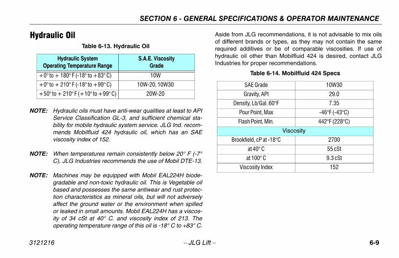
FICATIONS & OPERATOR MAINTENANCE
6-9
JLG recommendations, it is not advisable to mix oilst brands or types, as they may not contain the same
additives or be of comparable viscosities. If use ofoil other than Mobilfluid 424 is desired, contact JLG for proper recommendations.
Table 6-14. Mobilfluid 424 Specs
SAE Grade 10W30
Gravity, API 29.0
nsity, Lb/Gal. 60°F 7.35
Pour Point, Max -46°F (-43°C)
lash Point, Min. 442°F (228°C)
Viscosity
okfield, cP at -18°C 2700
at 40° C 55 cSt
at 100° C 9.3 cSt
Viscosity Index 152
SECTION 6 - GENERAL SPECI
3121216 – JLG Lift –
Hydraulic Oil
NOTE: Hydraulic oils must have anti-wear qualities at least to APIService Classification GL-3, and sufficient chemical sta-bility for mobile hydraulic system service. JLG Ind. recom-mends Mobilfluid 424 hydraulic oil, which has an SAEviscosity index of 152.
NOTE: When temperatures remain consistently below 20° F (-7°C), JLG Industries recommends the use of Mobil DTE-13.
NOTE: Machines may be equipped with Mobil EAL224H biode-gradable and non-toxic hydraulic oil. This is Vegetable oilbased and possesses the same antiwear and rust protec-tion characteristics as mineral oils, but will not adverselyaffect the ground water or the environment when spilledor leaked in small amounts. Mobil EAL224H has a viscos-ity of 34 cSt at 40° C. and viscosity index of 213. Theoperating temperature range of this oil is -18° C to +83° C.
Aside fromof differenrequired hydraulic Industries
Table 6-13. Hydraulic Oil
Hydraulic SystemOperating Temperature Range
S.A.E. ViscosityGrade
+0° to + 180° F (-18° to +83° C) 10W
+0° to + 210° F (-18° to +99° C) 10W-20, 10W30
+50° to + 210° F (+10° to +99° C) 20W-20
De
F
Bro

SECTION 6 - GENERAL SPECIFICATIONS & OPERATOR MAINTENANCE
6-1 3121216
ble 6-16. Mobil EAL 224H Specs
ype Biodegradable Vegetable Oil
osity Grade 32/46
fic Gravity .922
oint, Max -25°F (-32°C)
oint, Min. 428°F (220°C)
ting Temp. 0 to 180°F (-17 to 162°C)
eight 7.64 lb. per gal.(0.9 kg per liter)
Viscosity
40° C 37 cSt
00° C 8.4 cSt
sity Index 213
ust be stored above 32°F (0°C)
0 – JLG Lift –
Table 6-15. UCon Hydrolube HP-5046
Type Synthetic Biodegradable
Specific Gravity 1.082
Pour Point, Max -58°F (-50°C)
pH 9.1
Viscosity
at 0° C (32° F) 340 cSt (1600SUS)
at 40° C (104° F) 46 cSt (215SUS)
at 65° C (150° F) 22 cSt (106SUS)
Viscosity Index 170
Ta
T
ISO Visc
Speci
Pour P
Flash P
Opera
W
at
at 1
Visco
NOTE: M

FICATIONS & OPERATOR MAINTENANCE
6-11
Table 6-18. Exxon Univis HVI 26 Specs
pecific Gravity 32.1
Pour Point -76°F (-60°C)
Flash Point 217°F (103°C)
Viscosity
at 40° C 25.8 cSt
at 100° C 9.3 cSt
Viscosity Index 376
Mobil/Exxon recommends that this oil be checkedon a yearly basis for viscosity.
SECTION 6 - GENERAL SPECI
3121216 – JLG Lift –
Table 6-17. Mobil EAL Envirosyn H Specs
Type Synthetic Biodegradable
ISO Viscosity Grade 32
Specific Gravity .950
Pour Point, Max -59°F (-51°C)
Flash Point, Min. 514°F (268°C)
Viscosity
at 40° C 33.1 cSt
at 100° C 6.36 cSt
Viscosity Index 147
S
NOTE:
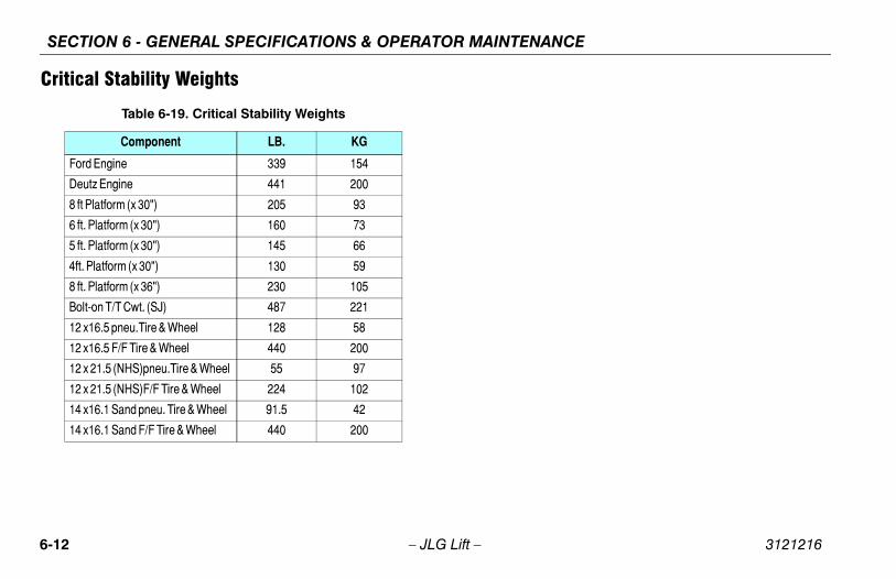
SECTION 6 - GENERAL SPECIFICATIONS & OPERATOR MAINTENANCE
6-1 3121216
Cri
2 – JLG Lift –
tical Stability Weights
Table 6-19. Critical Stability Weights
Component LB. KG
Ford Engine 339 154
Deutz Engine 441 200
8 ft Platform (x 30") 205 93
6 ft. Platform (x 30") 160 73
5 ft. Platform (x 30") 145 66
4ft. Platform (x 30") 130 59
8 ft. Platform (x 36") 230 105
Bolt-on T/T Cwt. (SJ) 487 221
12 x16.5 pneu.Tire & Wheel 128 58
12 x16.5 F/F Tire & Wheel 440 200
12 x 21.5 (NHS)pneu.Tire & Wheel 55 97
12 x 21.5 (NHS)F/F Tire & Wheel 224 102
14 x16.1 Sand pneu. Tire & Wheel 91.5 42
14 x16.1 Sand F/F Tire & Wheel 440 200

FICATIONS & OPERATOR MAINTENANCE
6-13
ation
SECTION 6 - GENERAL SPECI
3121216 – JLG Lift –
Serial Number LocationA serial number plate is affixed to the left rear side of the frame.If the serial number plate is damaged or missing, the machineserial number is stamped on the left side of the frame.
Figure 6-1. Serial Number Loc

SECTION 6 - GENERAL SPECIFICATIONS & OPERATOR MAINTENANCE
6-1 3121216
-40°F(-40°C)
-30F°(-34°C)
-20°F(-29°C)
-10°F(-23°C)
0°F(-18°C)
10°F(-12°C)
20°F(-7°C)
30°F(-1°C)
40°F(4°C)
50°F(10°C)
60°F(16°C)
70°F(21°C)
80°F(27°C)
90°F(32°C)
100°F(38°C)
110°F(43°C)
120°F(49°C)
WIA
AMBIENT AIRTEMPERATURE
Deutz - Sheet 1 of 2
4 – JLG Lift –
ENGINESPECIFICATIONS
ENGINE WILL START AND OPERATE AT THIS TEMPERATURETH THE RECOMMENDED FLUIDS, A FULLY CHARGED BATTERYND THE AID OF A COMPLETE JLG SPECIFIED COLD WEATHERPACKAGE (IE. ENGINE BLOCK HEATER, ETHER INJECTION OR
ENGINE WILL START AND OPERATE UNAIDED AT THISTEMPERATURE WITH THE RECOMMENDED FLUIDS AND A
FULLY CHARGED BATTERY.
SUMMERGRADEFUEL
WINTERGRADEFUEL
WINTERGRADEFUELWITH
KEROSENEADDED
NO OPERATION BELOW THISAMBIENT TEMPERATURE
NO OPERATION ABOVE THISAMBIENT TEMPERATURE
Figure 6-2. Engine Operating Temperature Specifications -
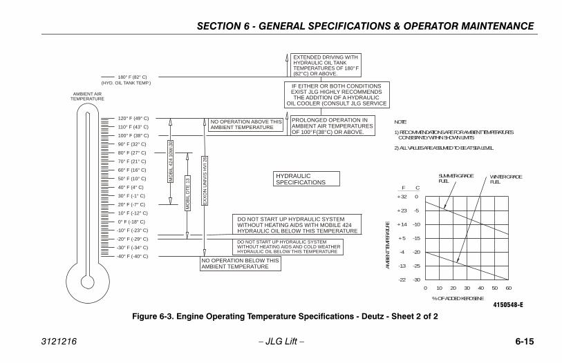
FICATIONS & OPERATOR MAINTENANCE
6-15
TH CONDITIONS RECOMMENDS
F A HYDRAULICULT JLG SERVICE
ERATION INPERATURESR ABOVE.
G WITHNKF 180°F
M E 424 ATURE
R
NOTE:
1) RECOMMENDATIONS ARE FOR AMBIENT TEMPERATURES CONSISTANTLY WITHIN SHOWN LIMITS
2) ALL VALUES ARE ASSUMED TO BE AT SEA LEVEL.
0+32
-5
-10
-15
-20
-25
-30
+23
+14
+5
-4
-13
-22
CF
0 10 20 30 40 50 60
% OF ADDED KEROSENE
AMBI
ENT T
EMPE
RATU
RE
SUMMER-GRADEFUEL
WINTER-GRADEFUEL
ions - Deutz - Sheet 2 of 24150548-E
SECTION 6 - GENERAL SPECI
3121216 – JLG Lift –
(HYD. OIL TANK TEMP.) IF EITHER OR BOEXIST JLG HIGHLYTHE ADDITION O
OIL COOLER (CONS
180° F (82° C)
-40° F (-40° C)
-30° F (-34° C)
-20° F (-29° C)
-10° F (-23° C)
0° F (-18° C)
10° F (-12° C)
20° F (-7° C)
30° F (-1° C)
40° F (4° C)
50° F (10° C)
60° F (16° C)
70° F (21° C)
80° F (27° C)
90° F (32° C)
100° F (38° C)
110° F (43° C)
120° F (49° C)
AMBIENT AIRTEMPERATURE
PROLONGED OPAMBIENT AIR TEMOF 100°F(38°C) O
EXTENDED DRIVINHYDRAULIC OIL TATEMPERATURES O(82°C) OR ABOVE.
NO OPERATION BELOW THISAMBIENT TEMPERATURE
MO
BIL
424
10W
-30
HYDRAULICSPECIFICATIONS
NO OPERATION ABOVE THISAMBIENT TEMPERATURE
DO NOT START UP HYDRAULIC SYSTEWITHOUT HEATING AIDS WITH MOBILHYDRAULIC OIL BELOW THIS TEMPER
DO NOT START UP HYDRAULIC SYSTEM WITHOUT HEATING AIDS AND COLD WEATHEHYDRAULIC OIL BELOW THIS TEMPERATURE
EXXO
N U
NIV
IS H
VI 2
6
MO
BIL
DTE
13
Figure 6-3. Engine Operating Temperature Specificat

SECTION 6 - GENERAL SPECIFICATIONS & OPERATOR MAINTENANCE
6-1 3121216
-40 F(-40 C)
-30 F(-34 C)
-20 F(-29 C)
-10 F(-23 C)
0 F(-18 C)
10 F(-12 C)
20 F(-7 C)
30 F(-1 C)
40 F(4 C)
50 F(10 C)
60 F(16 C)
70 F(21 C)
80 F(27 C)
90 F(32 C)
100 F(38 C)
110 F(43 C)
120 F(49 C)
A (
AMBIENT AIRTEMPERATURE
- Ford - Sheet 1 of 2
6 – JLG Lift –
ENGINE WILL START AND OPERATE ON LPG UNAIDED AT THIS TEMPERATUREWITH THE RECOMMENDED FLUIDS AND A FULLY CHARGED BATTERY.
NOTE: THIS IS THE LOWEST ALLOWABLE OPERATING TEMPERATURE ON LPG.
ENGINE WILL START AND OPERATE ON GASOLINE UNAIDED AT THIS TEMPERATUREWITH THE RECOMMENDED FLUIDS AND A FULLY CHARGED BATTERY.
FULLY CHARGED BATTERY AND THE AID OF A COMPLETE JLG SPECIFIED COLD WEATHER PACKAGE IE. ENGINE BLOCK HEATER, BATTERY WARMER AND HYDRAULIC OIL TANK HEATER)
ENGINESPECIFICATIONS
NO OPERATION BELOW THISAMBIENT TEMPERATURE
NO OPERATION ABOVE THISAMBIENT TEMPERATURE
Figure 6-4. Engine Operating Temperature Specifications
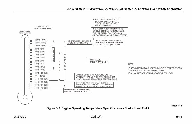
FICATIONS & OPERATOR MAINTENANCE
6-17
DITIONSMMENDSAULIC
LG SERVICE
ION INATURESBOVE.
ITH
0° F
E
NOTE:
1) RECOMMENDATIONS ARE FOR AMBIENT TEMPERATURES CONSISTANTLY WITHIN SHOWN LIMITS 2) ALL VALUES ARE ASSUMED TO BE AT SEA LEVEL.
tions - Ford - Sheet 2 of 24150548-E
SECTION 6 - GENERAL SPECI
3121216 – JLG Lift –
(HYD. OIL TANK TEMP.) IF EITHER OR BOTH CONEXIST JLG HIGHLY RECOTHE ADDITION OF A HYDROIL COOLER (CONSULT J
C)
C)
C)
C)
C)
180° F (82° C)
PROLONGED OPERATAMBIENT AIR TEMPEROF 100° F (38° C) OR A
EXTENDED DRIVING WHYDRAULIC OIL TANKTEMPERATURES OF 18(82° C) OR ABOVE.
NO OPERATION BELOW THISAMBIENT TEMPERATURE
MO
BIL
424
10W
-30
HYDRAULICSPECIFICATIONS
NO OPERATION ABOVE THISAMBIENT TEMPERATURE
DO NOT START UP HYDRAULIC SYSTEM WITHOUT HEATING AIDS WITH MOBILE 424 HYDRAULIC OIL BELOW THIS TEMPERATUR
DO NOT START UP HYDRAULIC SYSTEM WITHOUT HEATING AIDS AND COLD WEATHERHYDRAULIC OIL BELOW THIS TEMPERATURE
EX
XON
UN
IVIS
HVI
26
MO
BIL
DTE
13
-40° F (-40° C)
-30° F (-34° C)
-20° F (-29° C)
-10° F (-23° C)
0° F (-18° C)
10° F (-12° C)
20° F (-7° C)
30° F (-1° C)
40° F (4° C)
50° F (10° C)
60° F (16° C)
70° F (21° C)
80° F (27° C)
90° F (32° C)
100° F (38° C)
110° F (43° C)
120° F (49° C)
AMBIENT AIRTEMPERATURE
Figure 6-5. Engine Operating Temperature Specifica

SECTION 6 - GENERAL SPECIFICATIONS & OPERATOR MAINTENANCE
6-1 3121216
-40° °F(-40 C)
-30° °F(-34 C)
-20°F(-29°C)
-10°F(-23°C)
0°F(-18°C)
10°F(-12°C)
20°F(-7°C)
30°F(-1°C)
40°F(4°C)
50°F(10°C)
60°F(16°C)
70°F(21°C)
80°F(27°C)
90°F(32°C)
100°F(38°C)
110°F(43°C)
120°F(49°C)
AMBIENT AIRTEMPERATURE
aterpillar - Sheet 1 of 2
8 – JLG Lift –
ENGINESPECIFICATIONS
ENGINE WILL START AND OPERATE AT THIS TEMPERATUREWITH THE RECOMMENDED FLUIDS, A FULLY CHARGED BATTERYAND THE AID OF A COMPLETE JLG SPECIFIED COLD WEATHERPACKAGE (IE. ENGINE BLOCK HEATER, BATTERY WARMER AND
HYDRAULIC OIL TANK HEATER)
ENGINE WILL START AND OPERATE UNAIDED AT THISTEMPERATURE WITH THE RECOMMENDED FLUIDS AND A
FULLY CHARGED BATTERY.
NO OPERATION BELOW THISAMBIENT TEMPERATURE
NO OPERATION ABOVE THISAMBIENT TEMPERATURE
Figure 6-6. Engine Operating Temperature Specifications - C

FICATIONS & OPERATOR MAINTENANCE
6-19
IONSENDSLICSERVICE
TION INRATURES ABOVE.
WITH
180° F
4 RE
NOTE: 1) RECOMMENDATIONS ARE FOR AMBIENT TEMPERATURES CONSISTENTLY WITHIN SHOWN LIMITS
2) ALL VALUES ARE ASSUMED TO BE AT SEA LEVEL.
ns - Caterpillar - Sheet 2 of 24150548-E
SECTION 6 - GENERAL SPECI
3121216 – JLG Lift –
(HYD. OIL TANK TEMP.)IF EITHER OR BOTH CONDITEXIST JLG HIGHLY RECOMMTHE ADDITION OF A HYDRAUOIL COOLER (CONSULT JLG
180° F (82° C)
PROLONGED OPERAAMBIENT AIR TEMPEOF 100° F (38° C) OR
EXTENDED DRIVINGHYDRAULIC OIL TANKTEMPERATURES OF (82°C) OR ABOVE.
NO OPERATION BELOW THISAMBIENT TEMPERATURE
MO
BIL
424
10W
-30
HYDRAULICSPECIFICATIONS
NO OPERATION ABOVE THISAMBIENT TEMPERATURE
DO NOT START UP HYDRAULIC SYSTEM WITHOUT HEATING AIDS WITH MOBILE 42HYDRAULIC OIL BELOW THIS TEMPERATU
DO NOT START UP HYDRAULIC SYSTEM WITHOUT HEATING AIDS AND COLD WEATHERHYDRAULIC OIL BELOW THIS TEMPERATURE
EX
XO
N U
NIV
IS H
VI 2
6
MO
BIL
DTE
13
-40° F (-40° C)
-30° F (-34° C)
-20° F (-29° C)
-10° F (-23° C)
0° F (-18° C)
10° F (-12° C)
20° F (-7° C)
30° F (-1° C)
40° F (4° C)
50° F (10° C)
60° F (16° C)
70° F (21° C)
80° F (27° C)
90° F (32° C)
100° F (38° C)
110° F (43° C)
120° F (49° C)
AMBIENT AIRTEMPERATURE
Figure 6-7. Engine Operating Temperature Specificatio
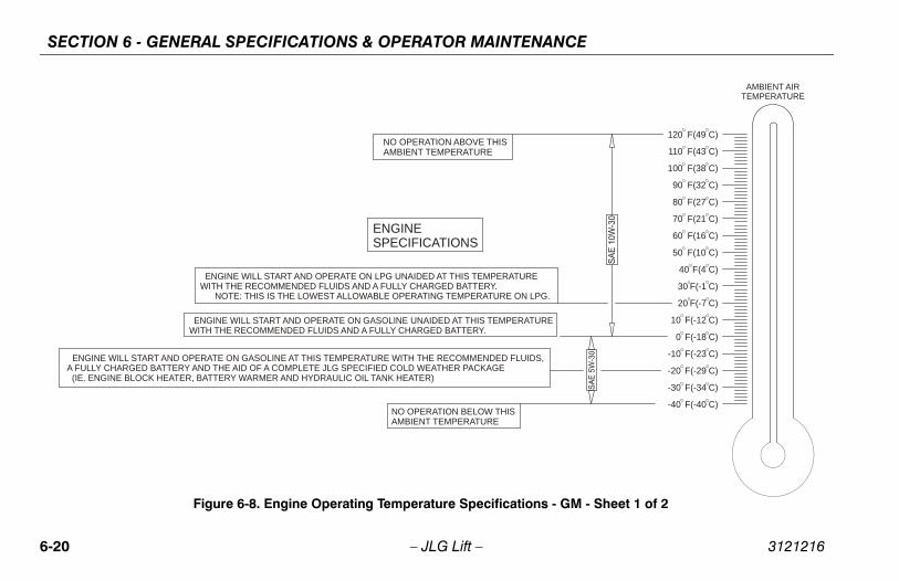
SECTION 6 - GENERAL SPECIFICATIONS & OPERATOR MAINTENANCE
6-2 3121216
-40 F(-40 C)
-30 F(-34 C)
-20 F(-29 C)
-10 F(-23 C)
0 F(-18 C)
10 F(-12 C)
20 F(-7 C)
30 F(-1 C)
40 F(4 C)
50 F(10 C)
60 F(16 C)
70 F(21 C)
80 F(27 C)
90 F(32 C)
100 F(38 C)
110 F(43 C)
120 F(49 C)
G.
RE
,
AMBIENT AIRTEMPERATURE
s - GM - Sheet 1 of 2
0 – JLG Lift –
ENGINE WILL START AND OPERATE ON LPG UNAIDED AT THIS TEMPERATUREWITH THE RECOMMENDED FLUIDS AND A FULLY CHARGED BATTERY.
NOTE: THIS IS THE LOWEST ALLOWABLE OPERATING TEMPERATURE ON LP
ENGINE WILL START AND OPERATE ON GASOLINE UNAIDED AT THIS TEMPERATUWITH THE RECOMMENDED FLUIDS AND A FULLY CHARGED BATTERY.
ENGINE WILL START AND OPERATE ON GASOLINE AT THIS TEMPERATURE WITH THE RECOMMENDED FLUIDS A FULLY CHARGED BATTERY AND THE AID OF A COMPLETE JLG SPECIFIED COLD WEATHER PACKAGE (IE. ENGINE BLOCK HEATER, BATTERY WARMER AND HYDRAULIC OIL TANK HEATER)
ENGINESPECIFICATIONS
NO OPERATION BELOW THISAMBIENT TEMPERATURE
NO OPERATION ABOVE THISAMBIENT TEMPERATURE
Figure 6-8. Engine Operating Temperature Specification
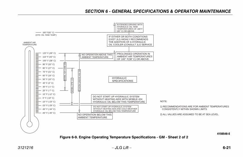
FICATIONS & OPERATOR MAINTENANCE
6-21
SS
VICE
INURESVE.
NOTE:
1) RECOMMENDATIONS ARE FOR AMBIENT TEMPERATURES CONSISTENTLY WITHIN SHOWN LIMITS
2) ALL VALUES ARE ASSUMED TO BE AT SEA LEVEL.
tions - GM - Sheet 2 of 24150548-E
SECTION 6 - GENERAL SPECI
3121216 – JLG Lift –
(HYD. OIL TANK TEMP.)IF EITHER OR BOTH CONDITIONEXIST JLG HIGHLY RECOMMENDTHE ADDITION OF A HYDRAULICOIL COOLER (CONSULT JLG SER
180° F(82° C)
PROLONGED OPERATIONAMBIENT AIR TEMPERATOF 100° F(38° C) OR ABO
EXTENDED DRIVING WITHHYDRAULIC OIL TANKTEMPERATURES OF 180°F(82° C) OR ABOVE.
NO OPERATION BELOW THISAMBIENT TEMPERATURE
MO
BIL
424
10W
-30
HYDRAULICSPECIFICATIONS
NO OPERATION ABOVE THISAMBIENT TEMPERATURE
DO NOT START UP HYDRAULIC SYSTEM WITHOUT HEATING AIDS WITH MOBILE 424 HYDRAULIC OIL BELOW THIS TEMPERATURE
DO NOT START UP HYDRAULIC SYSTEM WITHOUT HEATING AIDS AND COLD WEATHERHYDRAULIC OIL BELOW THIS TEMPERATURE
EXX
ON
UN
IVIS
HV
I 26
MO
BIL
DTE
13
-40° F (-40° C)
-30° F (-34° C)
-20° F (-29° C)
-10° F (-23° C)
0° F (-18° C)
10° F (-12° C)
20° F (-7° C)
30° F (-1° C)
40° F (4° C)
50° F (10° C)
60° F (16° C)
70° F (21° C)
80° F (27° C)
90° F (32° C)
100° F (38° C)
110° F (43° C)
120° F (49° C)
AMBIENT AIRTEMPERATURE
Figure 6-9. Engine Operating Temperature Specifica

SECTION 6 - GENERAL SPECIFICATIONS & OPERATOR MAINTENANCE
6-2 3121216
-40° °F(-40 C)
-30° °F(-34 C)
-20°F(-29°C)
-10°F(-23°C)
0°F(-18°C)
10°F(-12°C)
20°F(-7°C)
30°F(-1°C)
40°F(4°C)
50°F(10°C)
60°F(16°C)
70°F(21°C)
80°F(27°C)
90°F(32°C)
100°F(38°C)
110°F(43°C)
120°F(49°C)
AMBIENT AIRTEMPERATURE
- Perkins - Sheet 1 of 2
2 – JLG Lift –
ENGINESPECIFICATIONS
ENGINE WILL START AND OPERATE AT THIS TEMPERATUREWITH THE RECOMMENDED FLUIDS, A FULLY CHARGED BATTERYAND THE AID OF A COMPLETE JLG SPECIFIED COLD WEATHERPACKAGE (IE. ENGINE BLOCK HEATER, BATTERY WARMER AND
HYDRAULIC OIL TANK HEATER)
ENGINE WILL START AND OPERATE UNAIDED AT THISTEMPERATURE WITH THE RECOMMENDED FLUIDS AND A
FULLY CHARGED BATTERY.
NO OPERATION BELOW THISAMBIENT TEMPERATURE
NO OPERATION ABOVE THISAMBIENT TEMPERATURE
Figure 6-10. Engine Operating Temperature Specifications
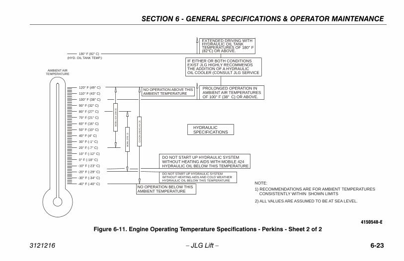
FICATIONS & OPERATOR MAINTENANCE
6-23
IONSNDS
LICSERVICE
TION INRATURES ABOVE.
WITH
180° F
4 RE
NOTE: 1) RECOMMENDATIONS ARE FOR AMBIENT TEMPERATURES CONSISTENTLY WITHIN SHOWN LIMITS
2) ALL VALUES ARE ASSUMED TO BE AT SEA LEVEL.
tions - Perkins - Sheet 2 of 24150548-E
SECTION 6 - GENERAL SPECI
3121216 – JLG Lift –
(HYD. OIL TANK TEMP.)IF EITHER OR BOTH CONDITEXIST JLG HIGHLY RECOMMETHE ADDITION OF A HYDRAUOIL COOLER (CONSULT JLG
180° F (82° C)
PROLONGED OPERAAMBIENT AIR TEMPEOF 100° F (38° C) OR
EXTENDED DRIVING HYDRAULIC OIL TANKTEMPERATURES OF (82°C) OR ABOVE.
NO OPERATION BELOW THISAMBIENT TEMPERATURE
MO
BIL
424
10W
-30
HYDRAULICSPECIFICATIONS
NO OPERATION ABOVE THISAMBIENT TEMPERATURE
DO NOT START UP HYDRAULIC SYSTEM WITHOUT HEATING AIDS WITH MOBILE 42HYDRAULIC OIL BELOW THIS TEMPERATU
DO NOT START UP HYDRAULIC SYSTEM WITHOUT HEATING AIDS AND COLD WEATHERHYDRAULIC OIL BELOW THIS TEMPERATURE
EX
XO
N U
NIV
IS H
VI 2
6
MO
BIL
DTE
13
-40° F (-40° C)
-30° F (-34° C)
-20° F (-29° C)
-10° F (-23° C)
0° F (-18° C)
10° F (-12° C)
20° F (-7° C)
30° F (-1° C)
40° F (4° C)
50° F (10° C)
60° F (16° C)
70° F (21° C)
80° F (27° C)
90° F (32° C)
100° F (38° C)
110° F (43° C)
120° F (49° C)
AMBIENT AIRTEMPERATURE
Figure 6-11. Engine Operating Temperature Specifica

SECTION 6 - GENERAL SPECIFICATIONS & OPERATOR MAINTENANCE
6-2 3121216
8
3 9
tion Diagram
4 – JLG Lift –
1 7 64
20
21, 22
14,15,16,17,18,19
8,9,10,11,12,13
5
Figure 6-12. Operator Maintenance and Lubrica
NOTE: Item #2 Not Shown
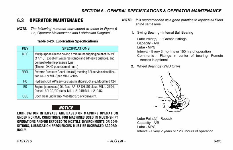
FICATIONS & OPERATOR MAINTENANCE
6-25
recommended as a good practice to replace all filtershe same time.
ing Bearing - Internal Ball Bearing
be Point(s) - 2 Grease Fittingsapacity - A/Rbe - MPGterval - Every 3 months or 150 hrs of operationomments - Fittings in center of bearing: RemoteAccess is optional
heel Bearings (2WD Only)
be Point(s) - Repackapacity - A/Rbe - MPGterval - Every 2 years or 1200 hours of operation
SECTION 6 - GENERAL SPECI
3121216 – JLG Lift –
6.3 OPERATOR MAINTENANCE
NOTE: The following numbers correspond to those in Figure 6-12., Operator Maintenance and Lubrication Diagram.
LUBRICATION INTERVALS ARE BASED ON MACHINE OPERATIONUNDER NORMAL CONDITIONS. FOR MACHINES USED IN MULTI-SHIFTOPERATIONS AND/OR EXPOSED TO HOSTILE ENVIRONMENTS OR CON-DITIONS, LUBRICATION FREQUENCIES MUST BE INCREASED ACCORD-INGLY.
NOTE: It isat t
1. Sw
LuCLuInC
2. W
LuCLuIn
Table 6-20. Lubrication Specifications
KEY SPECIFICATIONS
MPG Multipurpose Grease having a minimum dripping point of 350° F (177° C). Excellent water resistance and adhesive qualities, and being of extreme pressure type. (Timken OK 40 pounds minimum.)
EPGL Extreme Pressure Gear Lube (oil) meeting API service classifica-tion GL-5 or MIL-Spec MIL-L-2105
HO Hydraulic Oil. API service classification GL-3, e.g. Mobilfluid 424.
EO Engine (crankcase) Oil. Gas - API SF, SH, SG class, MIL-L-2104. Diesel - API CC/CD class, MIL-L-2104B/MIL-L-2104C.
OGL Open Gear Lubricant - Mobiltac 375 or equivalent.

SECTION 6 - GENERAL SPECIFICATIONS & OPERATOR MAINTENANCE
6-2 3121216
ulic Charge Filter
l - Change after first 50 hrs. and every 6 months0 hrs. thereafter or as indicated by Condition Indi-
r.
ulic Tank
oint(s) - Fill Capity - 40.0 gal. tank (151L) 52.0 gal. system.8L) HOl - Check Level daily; Change every 2 years or hours of operation.
6 – JLG Lift –
3. Wheel Drive Hub
Lube Point(s) - Level/Fill PlugCapacity - 17 oz. (0.5 L) - 1/2 FullLube - EPGLInterval - Check level every 3 months or 150 hrs of oper-
ation; change every 2 years or 1200 hours of operation
4. Hydraulic Return Filter
Interval - Change after first 50 hrs. and every 6 monthsor 300 hrs. thereafter or whenever Charge Filter isreplaced.
5. Hydra
Intervaor 30cato
6. Hydra
Lube PCapac
(196Lube -Interva
1200

FICATIONS & OPERATOR MAINTENANCE
6-27
il Change w/Filter - Deutz
be Point(s) - Fill Cap/Spin-on Element (JLG P/N7016331)apacity - 6.3 qt. (5.9 L) engine onlybe - EO
terval - Every Year or 1200 hours of operationomments - Check level daily/Change in accordancewith engine manual.
SECTION 6 - GENERAL SPECI
3121216 – JLG Lift –
7. Suction Strainers
Lube Point(s) - 2Interval - Every 2 years or 1200 hours of operation,
remove and clean at time of hydraulic oil change.
8. Oil Change w/Filter - Ford
Lube Point(s) - Fill Cap/Spin-on Element (JLG P/N7014501)
Capacity - 4.5 qt. (4.25 L)Lube - EOInterval - 3 Months or 150 hours of operationComments - Check level daily/Change in accordance
with engine manual.
9. O
Lu
CLuInC

SECTION 6 - GENERAL SPECIFICATIONS & OPERATOR MAINTENANCE
6-2 3121216
ange w/Filter - GM
Point(s) - Fill Cap/Spin-on Element (JLG P/N965)ity - 4.5 qt. (4.25 L) w/filter EOl - 3 Months or 150 hours of operationents - Check level daily/Change in accordanceengine manual.
8 – JLG Lift –
10. Oil Change w/Filter - Isuzu
Lube Point(s) - Fill Cap/Spin-on Element (JLG P/N7022111)
Capacity - 6 qt. (5.6L) engine; 6.5 qt. (6.1L) w/coolerLube - EOInterval - 3 Months or 150 hours of operationComments - Check level daily/Change in accordance
with engine manual.
11. Oil Change w/Filter - Caterpillar
Lube Point(s) - Fill Cap/Spin-on Element (JLG P/N7026855)
Capacity - 10 qt. (9.4 L)Lube - EOInterval - Every Year or 500 hours of operationComments - Check level daily/Change in accordance
with engine manual.
12. Oil Ch
Lube 7027
CapacLube -IntervaComm
with

FICATIONS & OPERATOR MAINTENANCE
6-29
el Filter - Deutz
be Point(s) - Replaceable Elementterval - Every Year or 600 hours of operation
el Filter - Isuzu
be Point(s) - Replaceable Elementterval - Every Year or 600 hours of operation
el Filter - Caterpillar
be Point(s) - Replaceable Elementterval - Every Year or 600 hours of operation
SECTION 6 - GENERAL SPECI
3121216 – JLG Lift –
13. Oil Change w/Filter - Perkins
Lube Point(s) - Fill Cap/Spin-on Element (JLG P/N7026855)
Capacity - 10 qt. (9.4 L)Lube - EOInterval - Every Year or 500 hours of operationComments - Check level daily/Change in accordance
with engine manual.
14. Fuel Filter - Ford
Lube Point(s) - Replaceable ElementInterval - Every Year or 600 hours of operation
15. Fu
LuIn
16. Fu
LuIn
17. Fu
LuIn

SECTION 6 - GENERAL SPECIFICATIONS & OPERATOR MAINTENANCE
6-3 3121216
nic Pressure Regulator (LP only)
l - 3 Months or 150 hours of operationents - Drain oil build up. Refer to Section 6.5,INING OIL BUILD UP FROM THE PROPANE REG-OR (Prior to S/N 0300109274)
0 – JLG Lift –
18. Fuel Filter (Gasoline) - GM
Lube Point(s) - Replaceable ElementInterval - Every 6 months or 300 hours of operation
19. Fuel Filter - Perkins
Lube Point(s) - Replaceable ElementInterval - Every Year or 600 hours of operation
20. Air Filter
Lube Point(s) - Replaceable ElementInterval - Every 6 months or 300 hours of operation or as
indicated by the condition indicator
21. Electro
IntervaComm
DRAULAT
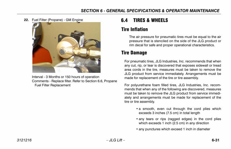
FICATIONS & OPERATOR MAINTENANCE
6-31
ES & WHEELS
tionr pressure for pneumatic tires must be equal to the airre that is stenciled on the side of the JLG product orcal for safe and proper operational characteristics.
age
atic tires, JLG Industries, Inc. recommends that whenip, or tear is discovered that exposes sidewall or treads in the tire, measures must be taken to remove theuct from service immediately. Arrangements must bereplacement of the tire or tire assembly.
rethane foam filled tires, JLG Industries, Inc. recom-at when any of the following are discovered, measuresaken to remove the JLG product from service immedi- arrangements must be made for replacement of the assembly.
a smooth, even cut through the cord plies whichexceeds 3 inches (7.5 cm) in total length
any tears or rips (ragged edges) in the cord plieswhich exceeds 1 inch (2.5 cm) in any direction
any punctures which exceed 1 inch in diameter
SECTION 6 - GENERAL SPECI
3121216 – JLG Lift –
22. Fuel Filter (Propane) - GM Engine
Interval - 3 Months or 150 hours of operationComments - Replace filter. Refer to Section 6.6, Propane
Fuel Filter Replacement
6.4 TIR
Tire InflaThe aipressurim de
Tire Dam
For pneumany cut, rarea cordJLG prodmade for
For polyumends thmust be tately andtire or tire
•
•
•

SECTION 6 - GENERAL SPECIFICATIONS & OPERATOR MAINTENANCE
6-3 3121216
If mn
Tir
JLbJLpmin
ically approved by JLG Industries Inc. do not filled or ballast filled tire assembly with a pneu-en selecting and installing a replacement tire,
l tires are inflated to the pressure recommended to size variations between tire brands, both tiresxle should be the same.
cement
lled on each product model have been designeduirements which consist of track width, tire pres- capacity. Size changes such as rim width, center, larger or smaller diameter, etc., without writtenmendations, may result in an unsafe conditionility.
2 – JLG Lift –
• any damage to the bead area cords of the tire
a tire is damaged but is within the above noted criteria, the tireust be inspected on a daily basis to insure the damage has
ot propagated beyond the allowable criteria.
e Replacement
G recommends a replacement tire be the same size, ply andrand as originally installed on the machine. Please refer to theG Parts Manual for the part number of the approved tires for a
articular machine model. If not using a JLG approved replace-ent tire, we recommend that replacement tires have the follow-g characteristics:
• Equal or greater ply/load rating and size of original
• Tire tread contact width equal or greater than original
• Wheel diameter, width, and offset dimensions equal tothe original
• Approved for the application by the tire manufacturer(including inflation pressure and maximum tire load)
Unless specifreplace a foammatic tire. Whensure that alby JLG. Dueon the same a
Wheel Repla
The rims instafor stability reqsure, and loadpiece locationfactory recomregarding stab
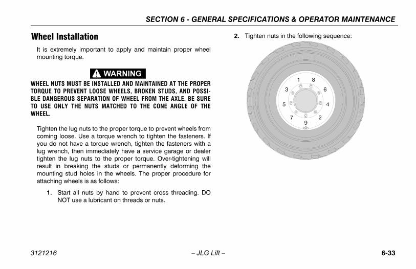
FICATIONS & OPERATOR MAINTENANCE
6-33
ghten nuts in the following sequence:
SECTION 6 - GENERAL SPECI
3121216 – JLG Lift –
Wheel InstallationIt is extremely important to apply and maintain proper wheelmounting torque.
WHEEL NUTS MUST BE INSTALLED AND MAINTAINED AT THE PROPERTORQUE TO PREVENT LOOSE WHEELS, BROKEN STUDS, AND POSSI-BLE DANGEROUS SEPARATION OF WHEEL FROM THE AXLE. BE SURETO USE ONLY THE NUTS MATCHED TO THE CONE ANGLE OF THEWHEEL.
Tighten the lug nuts to the proper torque to prevent wheels fromcoming loose. Use a torque wrench to tighten the fasteners. Ifyou do not have a torque wrench, tighten the fasteners with alug wrench, then immediately have a service garage or dealertighten the lug nuts to the proper torque. Over-tightening willresult in breaking the studs or permanently deforming themounting stud holes in the wheels. The proper procedure forattaching wheels is as follows:
1. Start all nuts by hand to prevent cross threading. DONOT use a lubricant on threads or nuts.
2. Ti

SECTION 6 - GENERAL SPECIFICATIONS & OPERATOR MAINTENANCE
6-3 3121216
ING OIL BUILD UP FROM THE NE REGULATOR (PRIOR TO S/N 09274)
course of normal operation oils may build insidey and secondary chambers of the propane pres-tor. These oils may be a result of poor fuel quality,tion of the fuel supply chain, or regional variatione up of the fuel. If the build up of the oil is signifi-an effect the operation of the fuel control system.ction 6.3, Operator Maintenance for maintenanceore frequent draining may be required if the fuel
been contaminated.
LTS WARM THE ENGINE TO OPERATING TEMPERA-RAINING. THIS WILL ALLOW THE OILS TO FLOWE REGULATOR.
the equipment to a well ventilated area. Ensurere no external ignition sources.
e engine and bring to operating temperature.
he engine running, close the manual tank valven the engine out of fuel.
4 – JLG Lift –
3. The tightening of the nuts should be done in stages. Fol-lowing the recommended sequence, tighten nuts perwheel torque chart.
4. Wheel nuts should be torqued after first 50 hours ofoperation and after each wheel removal. Check torqueevery 3 months or 150 hours of operation.
6.5 DRAINPROPA03001
During thethe primarsure regulacontaminain the makcant this cRefer to Seintervals. Msupply has
FOR BEST RESUTURE BEFORE DFREELY FROM TH
1. Move there a
2. Start th
3. With tand ru
Table 6-21. Wheel Torque Chart
TORQUE SEQUENCE
1st Stage 2nd Stage 3rd Stage
40 ft. lbs.(55 Nm)
100 ft. lbs.(130 Nm)
170 ft. lbs.(255 Nm)

FICATIONS & OPERATOR MAINTENANCE
6-35
move the retainer clip for the LPG fuel temperaturensor and remove the sensor from the regulator body.
ve a small container ready to collect oil that will drainely from the regulator at this point.
nce all of the oil has been drained, reinstall the LPGel temperature sensor and reconnect the electricalnnector.
pen the fuel tank manual valve.
art the engine and verify all connections are secure.
ispose of any drained oil per local regulations in a safed proper fashion.
SECTION 6 - GENERAL SPECI
3121216 – JLG Lift –
4. Push in the Emergency Switch once the engine stops.
5. Disconnect the electrical connection to the LPG fueltemperature sensor in the auxiliary fuel port of the EPR.
6. Rese
NOTE: Hafre
7. Ofuco
8. O
9. St
10. Dan

SECTION 6 - GENERAL SPECIFICATIONS & OPERATOR MAINTENANCE
6-3 3121216
6.6
ReNSTALL THE FILTER MAGNET INTO THE HOUSINGING NEW SEAL
the mounting plate to lock off O-ring seal.
the retaining bolt seal (if equipped).
the housing seal.
he magnet into the bottom of the filter housing.
the filter into the housing.
pped, install the retaining bolt into the filter hous-
the filter up to the bottom of the electric lock off.
n the filter to 106 in lbs (12 Nm).
manual shut-off valve. Start the vehicle and leak the propane fuel system at each serviced fitting.o Propane Fuel System Leak Test.
6 – JLG Lift –
PROPANE FUEL FILTER REPLACEMENT
moval1. Relieve the propane fuel system pressure. Refer to Pro-
pane Fuel System Pressure Relief.
2. Disconnect the negative battery cable.
3. Slowly loosen the Filter housing and remove it.
4. Pull the filter housing from the Electric lock off assembly.
5. Remove the filter from the housing.
6. Locate Filter magnet and remove it.
7. Remove and discard the housing seal.
8. Remove and discard the retaining bolt seal.
9. Remove and discard mounting plate to lock off O-ringseal.
Installation
BE SURE TO REIBEFORE INSTALL
1. Install
2. Install
3. Install
4. Drop t
5. Install
6. If equiing.
7. Install
8. Tighte
9. Open checkRefer t
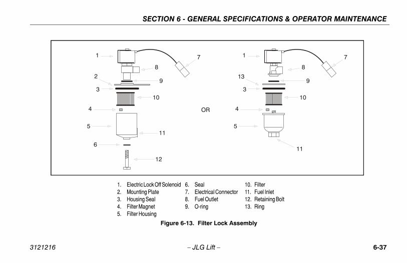
FICATIONS & OPERATOR MAINTENANCE
6-37
7
8
9
10
11
10. Filter11. Fuel Inlet12. Retaining Bolt13. Ring
bly
SECTION 6 - GENERAL SPECI
3121216 – JLG Lift –
1 1
2 13
3 3
4 4
5 5
6
7
8
9
OR
10
11
12
1. Electric Lock Off Solenoid2. Mounting Plate3. Housing Seal4. Filter Magnet5. Filter Housing
6. Seal7. Electrical Connector8. Fuel Outlet9. O-ring
Figure 6-13. Filter Lock Assem

SECTION 6 - GENERAL SPECIFICATIONS & OPERATOR MAINTENANCE
6-3 3121216
6.7
THEPSI INJUAPPPON
To
RESTEMCON
EMENTAL INFORMATIONng information is provided in accordance with thets of the European Machinery Directive 2006/42/nly applicable to CE machines.
powered machines, the equivalent continuous A-ound pressure level at the work platform is lessA)
ustion engine powered machines, guaranteeder Level (LWA) per European Directive 2000/14/
Emission in the Environment by Equipment forors) based on test methods in accordance withart B, Method 1 and 0 of the directive, is 104 dB.
ion total value to which the hand-arm system isdoes not exceed 2,5 m/s2. The highest root meanue of weighted acceleration to which the wholejected does not exceed 0,5 m/s2.
8 – JLG Lift –
PROPANE FUEL SYSTEM PRESSURE RELIEF
PROPANE FUEL SYSTEM OPERATES AT PRESSURES UP TO 312(21.5 BAR). TO MINIMIZE THE RISK OF FIRE AND PERSONALRY, RELIEVE THE PROPANE FUEL SYSTEM PRESSURE (WHERE
LICABLE) BEFORE SERVICING THE PROPANE FUEL SYSTEM COM-ENTS.
relieve propane fuel system pressure:
1. Close the manual shut-off valve on the propane fueltank.
2. Start and run the vehicle until the engine stalls.
3. Turn the ignition switch OFF.
IDUAL VAPOR PRESSURE WILL BE PRESENT IN THE FUEL SYS-. ENSURE THE WORK AREA IS WELL VENTILATED BEFORE DIS-NECTING ANY FUEL LINE.
6.8 SUPPLThe followirequiremenEC and is o
For electricWeighted sthan 70dB(
For combSound PowEC (NoiseUse OutdoAnnex III, P
The vibratsubjected square valbody is sub

TION 7 - INSPECTION AND REPAIR LOG
7-1
D REPAIR LOG
ir Log
nts
SEC
3121216 – JLG Lift –
SECTION 7. INSPECTION ANMachine Serial Number _______________________________________
Table 7-1. Inspection and Repa
Date Comme

SECTION 7 - INSPECTION AND REPAIR LOG
7-2 3121216
og
– JLG Lift –
Table 7-1. Inspection and Repair L
Date Comments

TRA
NS
FE
R O
F O
WN
ER
SH
IP
To P
rod
uct
Ow
ner
:If
yo
u n
ow
ow
n b
ut
AR
E N
OT
th
e o
rig
inal
pu
rch
aser
of
the
pro
du
ct c
over
ed b
y th
is
man
ual
, we
wo
uld
like
to
kn
ow
wh
o y
ou
are
. Fo
r th
e p
urp
ose
of
rece
ivin
g s
afet
y-re
late
d
bulle
tin
s, it
is v
ery
imp
ort
ant
to k
eep
JL
G In
du
stri
es, I
nc.
up
dat
ed w
ith
th
e cu
rren
t ow
ner
ship
of
all J
LG
pro
du
cts.
JL
G m
ain
tain
s ow
ner
info
rmat
ion
for
each
JL
G p
rod
uct
an
d u
ses
this
info
rmat
ion
in c
ases
wh
ere
ow
ner
no
tifi
cati
on
is n
eces
sary
.P
leas
e u
se t
his
form
to
pro
vid
e JL
G w
ith
up
dat
ed in
form
atio
n w
ith
reg
ard
to
th
e cu
rren
t ow
ner
ship
of
JLG
pro
du
cts.
Ple
ase
retu
rn c
om
ple
ted
form
to
th
e JL
G P
rod
uct
S
afet
y &
Rel
iab
ility
Dep
artm
ent
via
facs
imile
or
mai
l to
ad
dre
ss a
s sp
ecif
ied
bel
ow
.
Th
ank
You
,P
rod
uct
Saf
ety
& R
elia
bili
ty D
epar
tmen
tJL
G In
du
stri
es, I
nc.
1322
4 F
ou
nta
inh
ead
Pla
zaH
ager
stow
n, M
D21
742
US
ATe
lep
ho
ne:
+1-
717-
485-
6591
Fax:
+1-
301-
745-
3713
NO
TE
: L
ease
d o
r re
nte
d u
nit
s sh
ou
ld n
ot
be
incl
ud
ed o
n t
his
form
.
Mfg
. Mo
del
: __
____
____
____
____
____
____
____
____
____
____
____
____
____
____
____
_
Ser
ial N
um
ber
: __
____
____
____
____
____
____
____
____
____
____
____
____
____
____
__
Pre
vio
us
Ow
ner
: __
____
____
____
____
____
____
____
____
____
____
____
____
____
____
_
Ad
dre
ss:
____
____
____
____
____
____
____
____
____
____
____
____
____
____
____
____
_
____
____
____
____
____
____
____
____
____
____
____
____
____
____
____
____
____
____
_
Co
un
try:
__
____
____
____
____
____
___
Tele
ph
on
e: (
____
___)
___
____
____
____
____
_
Dat
e o
f Tr
ansf
er:
____
____
____
____
____
____
____
____
_
Cu
rren
t O
wn
er:
____
____
____
____
____
____
____
____
____
____
____
____
____
____
____
Ad
dre
ss:
____
____
____
___ _
____
____
____
____
____
____
____
____
____
____
____
____
_
____
____
____
____
____
____
____
____
____
____
____
____
____
____
____
____
____
____
_
Co
un
try:
__
____
____
____
____
____
___
Tele
ph
on
e: (
____
___)
___
____
____
____
____
_
Wh
o in
yo
ur
org
aniz
atio
n s
ho
uld
we
no
tify
?
Nam
e:
____
____
____
____
____
____
____
____
____
____
____
____
____
____
____
____
___
Tit
le:_
____
____
____
____
____
____
____
____
____
____
____
____
____
____
____
____
___
��
����
���
�
��
� ��
�
�
��
��


Corporate Office
JLG Industries, Inc.
1 JLG Drive
McConnellsburg PA. 17233-9533
USA
(717) 485-5161
(717) 485-6417
JLG Worldwide LocationsJLG Industries (Australia)P.O. Box 511911 Bolwarra RoadPort MacquarieN.S.W. 2444Australia
+61 2 65 811111
+61 2 65813058
JLG Latino Americana Ltda.Rua Eng. Carlos Stevenson,80-Suite 7113092-310 Campinas-SPBrazil
+55 19 3295 0407
+55 19 3295 1025
JLG Industries (UK) LtdBentley HouseBentley AvenueMiddletonGreater ManchesterM24 2GP - England
+44 (0)161 654 1000
+44 (0)161 654 1001
JLG France SASZ.I. de Baulieu47400 FauilletFrance
+33 (0)5 53 88 31 70
+33 (0)5 53 88 31 79
JLG Deutschland GmbHMax-Planck-Str. 21D - 27721 Ritterhude - IhlpohlGermany
+49 (0)421 69 350 20
+49 (0)421 69 350 45
JLG Equipment Services Ltd.Rm 1107 Landmark North39 Lung Sum AvenueSheung Shui N. T.Hong Kong
(852) 2639 5783
(852) 2639 5797
JLG Industries (Italia) s.r.l.Via Po. 2220010 Pregnana Milanese - MIItaly
+39 029 359 5210
+39 029 359 5845
Oshkosh-JLG Singapore Technology Equipment Pte Ltd29 Tuas Ave 4,Jurong Industrial EstateSingapore, 639379
+65-6591 9030
+65-6591 9031
Plataformas Elevadoras JLG Iberica, S.L.Trapadella, 2P.I. Castellbisbal Sur08755 Castellbisbal, BarcelonaSpain
+34 93 772 4700
+34 93 771 1762
JLG Sverige ABEnkopingsvagen 150Box 704SE - 176 27 JarfallaSweden
+46 (0)850 659 500
+46 (0)850 659 534
www.jlg.com
3121216