Embed Size (px)
Citation preview

KAERI/TR 1301/99
KR9900251
Operation and Maintenance Techniques
of 1-Ton Bucket Elevator in IMEF
3 1 - 0 2
1999\3 4
_ i —

I .
II.
Aj^Aj^uI # (3x6x10
25x25x150 cm
•HI ^£]<H SIfe i 5 S ^ ^o« ^ 7 H 9-S*)-£^ £i«H SlcK ^ g ? ^ ! ^ ^ Ml
£ Ml
uf. 7 M H
III. ^ ^ - ^ tfl-g- 51
51
- 2 -

SUMMARY
I . Project Title
Operation and Maintenance Techniques of Pool Water Purification System
(PWPS) in IMEF.
II. Objective and Importance of the Project
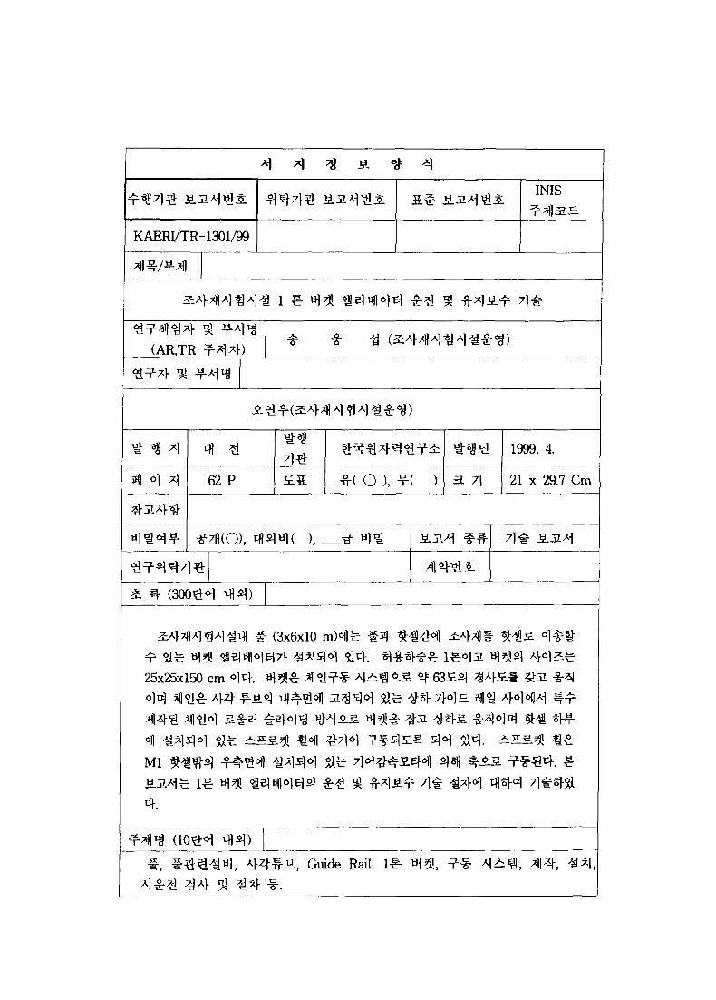
IMEF pool is used as a pathway between pool and hot cell in order to
transfer (incoming and outgoing) irradiated materials.
Transfer is performed by 1-ton bucket elevator which is moved inside the
rectangular tube installed between pool and Ml hot cell. Allowable load
capacity of the bucket elevator is 1-ton and its size is 25x25x150 cm.
Bucket is drived by chain system which is moved up and down through the
guide rail. Guide rail is installed in rectangular tube that is tilted
about 63° .
Chain which is moved by means of the roller sliding method is drived by
sprocket wheel being rotated by the shaft and the shaft is drived by gear
dreducing motor.
Gear reducing motor is installed outside of Ml hot cell wall.
1-ton bucket elevator consists of five parts.
- Rectangular tube
- Guide rail
- Chain
- Bucket
- Driving system
III. Scope and Contents of the Project
In this report operation and maintenance techniques of 1-ton bucket
elevator in IMEF are described in detail on the focus as follows :
- 3 -

Installation and characteristics
Fabrication, installation and demonstraction
Operation and maintenance techniques
- 4 -

CONTENTS
Summary 3
Chapter 1. Introdction 12
1. Pool
2. Pool Fcility
a. Pool Liner
b. Shielding
c. Pool Water Purification System
3. 1-Ton Bucket Elevator 13
Chapter 2. Status of Technology Development 14
Section 1. Description of Equipments
1. Rectangular Tube
2. Guide Rail
3. Stainless Roller Chain
4. Bucket
5. Drive System 15
Section 2. Technical Specification
1. Rectangular Tube Quality Standards
a. General
b. Codes and Standards
c. Materials
Section 3. Design of Equipments
1. 1-Ton Bucket Elevator Design Data
2. Geared Motor Design Data
3. Stainless Roller Chain Design Data
4. Efficient Design Data
Section 4. Detail Design of Equipments
1. Chain
2. Hoisting Speed and Motor Power 16
3. Shaft 17
Chapter 3. Contents of R&D and Results 18
- 5 -
Section 1. Fabrication
1. Genera]
2. Welding
Section 2. Fabricated Inspection of Equipments
1. Bucket Elevator & Rectangular Tube
7}. Fabrication Inspection & Test Procedure
Section 3. NDT Test
1. Leak Test Procedure
2. Liquid Penetration Examination Procedure
Section 4. Materials & Fabrication Inspection
1. Tensile Test Procedure
2. Genera] Welding Procedure
Chapter 4. Achievement of R&D Goal & Contribution 23
Section 1. Installation of Equipments
1. Rectangular Tube Installation Procedure
2. Bucket Elevator Installation Procedure 25
Chapter 5. Application of Research and Development
Results 28
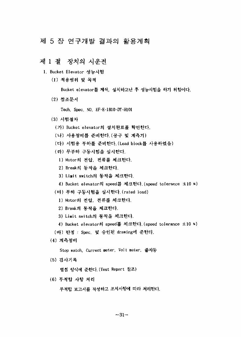
Section 1. Performance Test of Equipments
Chapter 6. Bibliography 29
Drawing List 30
Table List 37
Attachment 1. Operation Manual of 1-Ton Bucket Elevator 52
- 6 -

^
2
Summary 3
all 1 # *l * 12
2.
3. 1 ^ a | ^ ^eltHl°)ei 13
^ M | ^ 7 l # 7fl«J^% 14
1 ^ ^^1^1 Tflja.
1. Rectangular tube
2. Guide Rail
3. Stainless Roller Chain
4. »13!5. ^~§~?- 15
2 *l 2| *l«g Tfl1. Rectangular tube quality standards
Lf. Codes and Standards
CK Materials 16
3 H 4 ^ 1 ^ S£T\]
1.1 Ton Bucket Elevator Design Data
2.Geared Motor Design Data
3. Stainless Roller Chain Design Data 17
4.Efficient Design Data
1. Chain
2. Hoisting Speed and Motor Power
3. Shaft 18
91 4^ 20
- 7 -

2.
2 1
1. Bucket Elevator and Rectangular Tube
(1)
(2)
(3) >M|34 21(4) -¥-#34(5) H 9-2:# ^A>
(6) ^^J^4 22(7)
(8)
(9)
(10) ^ # 4 * ^ ^ 4 23
(11)
3 ^ NDT ^ 4
1. Leak Test
(1) aj-g-g*! 91
(2)
(3)
(4)
(5) 4^^4(6) 4 ^ ^ ^ 24(7) 4 W ^J4i
2. Liquid Penetration Examination Procedure
4 *J
(1)
(2)
(3) 4 ^ aj*|.
- 8 -

(4) 3*}7|4* 25
(5) ->M*m ei2. General Welding Procedure
| 26
1. Rectangular Tube
(l) -^ 51
(2)
(3)
(4) -i*l-§- Drawing
(5) ^ 1 A ^ 27
(6) Tolerance
(7) Tll^^U) 28
(8) 347)^-
2. Rectangular Tube & Bucket Elevator
(1)
(2)
(3)
(4) ^*l-g- Drawing
(5) ^^l-fi.^ 29
(6) * 1 ^ H ^ o j 30
(7) «^Al^.^ ^4
31
(1)
(2)
(3)
(4)
(5)
(6)
6 ^ ^JL£*i 32
-Y- 1. 1-Ton Bucket Elevator &*i3!*M 53
— 9 —
1. 1-Ton Bucket Elevator Assembly Dwg. 33
2. Guide Rail Detail of 1-Ton Bucket Elevator 34
3. Driving Unit Assembly of 1-Ton Bucket Elevator 35
4. Guide Rail Support & Tray Detail 36
5. Geared Motor Base Detail of 1-Ton Bucket Elevator 37
6. Bearing Block Base Detail of 1-Ton Bucket Elevator 38
- 10 -

3: 1. Leak Test Report 39
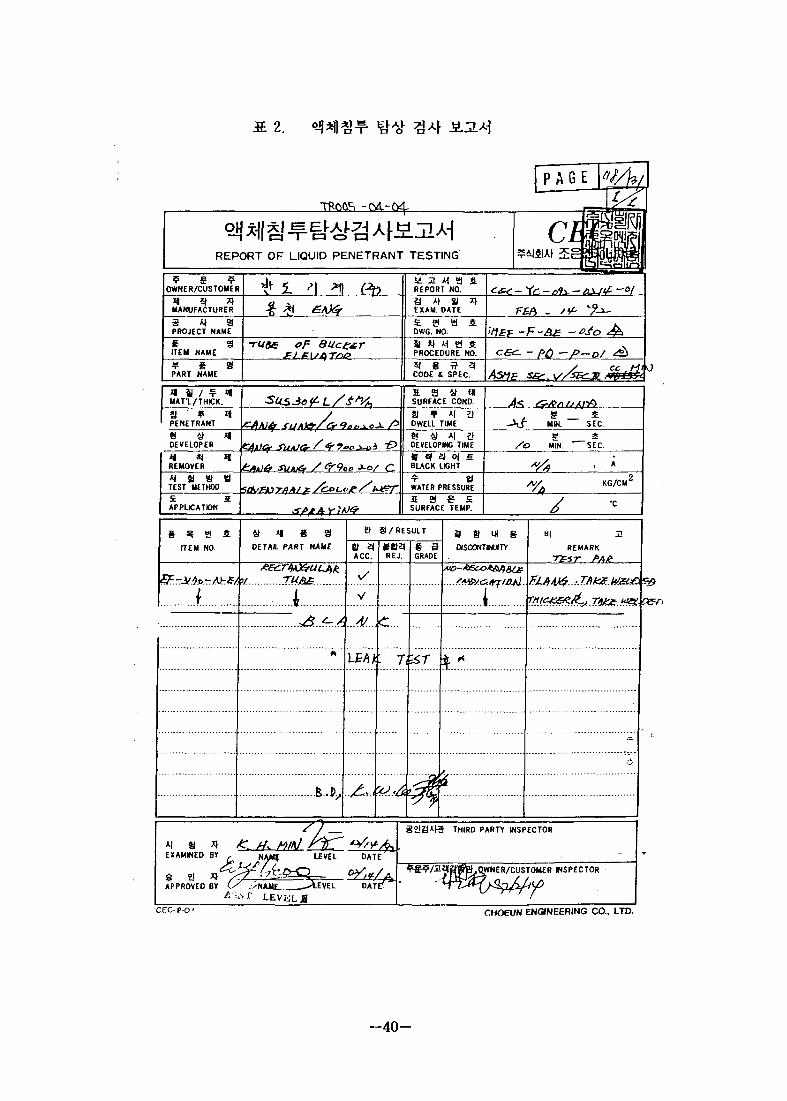
X 2. o J N l ^ 1HJ 3 4 MJ.^ 40
3£ 3. Report of Inspection 41
3: 4. Report of Inspection 42
3- 5. Report of Inspection 43
3. 6. ^«/tfg 7)-§-7l -^ 44
S. 7. ^ - ^ . ^ ^ Elevation *r$ 45
S. 8. ^ « . * } ^ 7l#7| ^ 46
JE 9. ^w. ^ } £ ^ 4 47
5. 10. Materials Specification 48
£ 11. *«.^*1 ^ 4 -S.J14 49
a 12. Bucket Elevator Rail # 3 *fl3. 50
SL 13. Bucket Elevator Rail ^SL %}3. 51
S. 14. Test Report 52
- 11 -

1 S- M
^ E - l Ml
(SSE) ^ ^
K [1]
2.
6m, ^ 3 m,
(Pool Liner)
6 mm,
mm 7fl-?(0pening)
. [2]
H 160 cms.
]T= 3 .5 m
MeV
"69 0 x 10"6
- 12 -
fe- 4 4" *\*]B$) t]
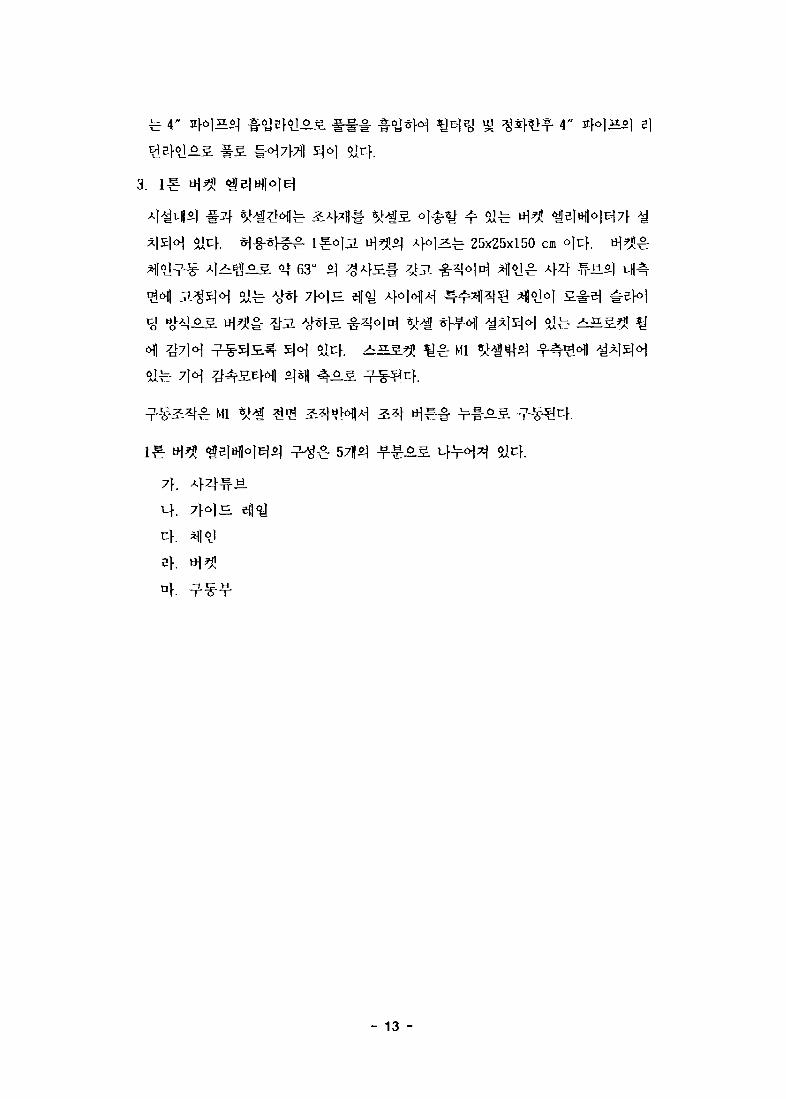
3.
l ^ ^ 25x25x150 cm
63°
^ Mi
Mi
7}.
- 13 -

1, Rectangular Tube
r\. A}Z| ^u.o | q^o. s u s 304Lo]Qi ^ ] 5 t plateS. ^ ^ | ^ 8.75 m
^ ^ 1 ^ 2.8 molt}. A}Z|^ .H.^ oo^ open flange typeAS. pool^ opening 4 o |
Zi^ 4.75x0.6 mo)t Pool liner<>)| «g^M Si3. ^ ^ opening 4°)Z:-b
0.8x0.6 mS. ^ bottom linerofl ^15]<H »Irf. Afzf tube^ *M ^ -rfl^ofl
«|*| ^\7\ 3.3. ^-Ti^-HS. ? H ^ ' iJ H|S^|o| ^ [ ^ ^ o. o.x ,^7 , ^ , ^ H
fixing angle (50x50x4 t,CS) n| 50 cm # 3 ^ 5 . %• 137fl5] reinforcing angle
(50x50x4 t.CSH i | ^ # v\t\ 2.%H°\ $1°-^ Lfl^o
thicker plate (sus, 5 t)7f « O ^ M 6 ^ ^^]5]<>j Sl-2.,
2. 7
H6i|<y£ 22
o^£S *fnf 4z|-^-«. uH4<Hl *l*l£M H-b thicker plate (sus, 5
<H] thick piate#
3. A
4.
^*1 4<>]Z:^ 25x25x150 cm^lc}. l i f t ing lug pi
30 cm S\ &>]3. thick platef- ^ H
^ 18
- 14 -
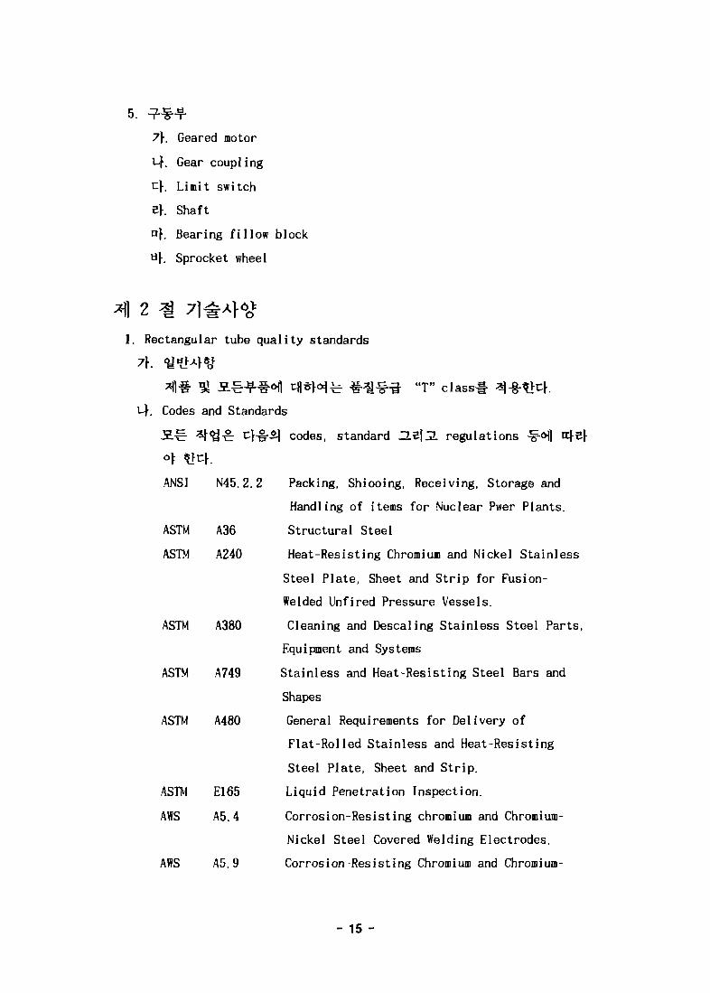
5.
7\. Geared motor
i-|. Gear coupling
cf. Limit switch
5}. Shaft
of. Bearing fillow block
U}. Sprocket wheel
1. Rectangular tube quality standards
*H# « 5L^-f#*l| c||*Hfe # « ^ "T" classl-
1-4. Codes and Standards
-2.-C- ^ ^ ^ c : 4^5-^1 codes, standard He|^L regulations
ANSI N45.2.2 Packing, Shiooing, Receiving, Storage and
Handling of items for Nuclear Pwer Plants.
ASTM A36 Structural Steel
ASTM A240 Heat-Resisting Chromium and Nickel Stainless
Steel Plate, Sheet and Strip for Fusion-
Welded Unfired Pressure Vessels.
ASTM A380 Cleaning and Descaling Stainless Steel Parts,
Equipment and Systems
ASTM A749 Stainless and Heat-Resisting Steel Bars and
Shapes
ASTM A480 General Requirements for Delivery of
Flat-Rolled Stainless and Heat-Resisting
Steel Plate, Sheet and Strip.
ASTM E165 Liquid Penetration Inspection.
AWS A5.4 Corrosion-Resisting chromium and Chromium-
Nickel Steel Covered Welding Electrodes.
AWS A5.9 Corrosion-Resisting Chromium and Chromium-
- 15 -

Nickel Steel Covered Welding rods and Bare
Electrodes.
AWS Dl.l Structural Wlding Code.
ASME SEC. v Boiler and Pressure Vessel Code,Nondestruc-
tive Examination.
Boiler and Pressure Vessel Code, Welding and
Brazing Qualification.
SNT-TC-1A Recommended Particle Suplement D
(ASNT-American Society for Nondestructive
Testing),
t}. Materials
(l) sRW^
ASTM SEC. ix
ASNT
2)
3)
Mill sheets
NDE efl£E 4
(2) aj-g- Materials
1) Plate, Thicker Plate and Back Strip : ASTM A240 Type 304L
lfe Cold-Rolled, Annealed and
2) Corner and Edge Angle : ASTM A479 Type 304L
3) Reinforcing Angle : ASTM A36
4) Welding Materials : -D(JA|ao^ APPENDIX 4HW-03
1. 1-ton bucket elevator design data
• Rated load Q = 1000 kg
• Self weight of bucket Ql = 180 kg
• Hoisting speed V = 5 m/min
2. Geared motor design data
• Power kW = 2.2
- 16 -

• Reduction ratio
3. Stainless roller chain design data
• Stainless roller chain
• Dia x Pitch
• No. of chain
• Breaking strength
4. Efficient design data
• Dynamic coefficient
• Static coefficient
I =
RF
• 1/377
450-S
022 x p 101.6
N =
P =
</>
0
2 falls
8000 kg
= 1.4
= 1.1
4 41. Chain (RF450-s)
• Chain breaking strength P = 8000 kg
• No. of chain N = 2
• Efficiency of chain sprocket TJ = 0.95
7\. Chain tension load = PI
PI = (Q + Qi)/N = 1180/2 = 590 kg
uf. Chain safety factor = S.F
S.F = P/Pj x v = 8000/590 x 0. 95 = 12.88>7 o. k
2. Hoisting speed & motor power
7}. Speed = V
V = N i x i x D x K
= 1720 x 1/377 x 0.3288 x x = 4. 72 m/min
Ni = Input rpm = 1720 rpm
i = Reduction ratio = 1/377
D = Sprocket Dia. = 328.8 mm
1-4. Motor power = kW
- 17 -

kw_ (Q+QX)xV6120* ?
1180^4.71 -6120*0.95 -
o.k
. Motor torque = Tm
Tm = Motor torque (Geared motor output) = 320 kg-m
Ts = Shaft torque = 194 kg-m
7} - Efficient = 0.95
D = Sprocket Dia. = 328.8 mm
Ts = P x D/2 = 1180 x 0.3288/2 = 194 kg-m
Tm = Ts/ 7] = 194/0.95 = 204.2 kg-m < 320 kg-m o.k
3. Shaft
Ll =25.6 38.8 L 1=25.0
[.=90
PI
PI = 1180/2 = 590 kg
Shaft Dia. = 5.5 cm
1) Area of shaft
2) Section module
A = 23.75 cmz
Zx = 16.33 cm3
3) Polar modulus of section Zp = 32.66 cm
Shaft torque (Ts)
Ts = (2 x PI) x D/2
= 1180 x 32.88/2 = 19399.2 kg-cm
Torsional stress ( r )
r = Ts/Zp = 19399.2/32.66 =593.97 kg/cm2
Bending moment (M)
M = P x LI = 590 x 25.6 = 15104 kg-cm
- 18 -

Bending s t r e s s ( a )
G - M/Zx = 15104/16.33t 924.9 kg/cm2
* Equivalent bending s t ress ( <7e)
<Te= a2 + 3 • r z
= 924.9Z + 3 x 593. 972 = 1383.4 kg/cm2 < 2100 kg/cm2
o.k
(Used metal sus 304 - yield strength = 2100 kg/cm2)
- 19 -

1) Cutting, Firming and bending 4*0* -^TT AffS D1.15] SECTION
2) Stainless Steel^ Forming^] <g-g- 7f^5it:f'3 Solution
annealing, Pickling and passivation^*^
3) 4 < a ^ « W « f ^?I1OJ fit-upA|
2. -g-3
1) o))<g - 5 ^ ? 1 interface <g*Jel, ^ ^ ^ ^^1 4 ^ ^ : APPENDIX
4HW-03 *£ 1
2) -g-3^<3
3) - ^ ^ ^ M 31 qualified^ -§-^Af6] ^ - f i - ^ ASME SEC. k
4) Stainles Steel -§-^4^^l ^ ^ 1 4 ^ AWS Dl.l^ SECTION 3
SUBARTICLE 3. 7*cH 4 ^ - ^ under cutting^ ^S.^-^]$] 5^
5) 3.E butt -8-^^r full Penetration -g-^ ^l^H^ * H
double welded layers-i-
21. Bucket elevator & Rectangular tube
7\.
4, 71*71 4 ** -a4*H6l:
(l)
(2)
- 20 -

51S. W.
(3)
2) * f « | ^ ^ A)t!£ ^^>c}. (Maker mill sheet
3) 7]7)]^ A ] ^ ^ . ^ ^ c K (Maker mill sheet
4)
2) Sf«|^^ 4^-i- ^ ^ c f . (Maker mill sheet
3) 7l7fl3 4fl-& * S ^ K (Maker mill sheet
4)
itfef
(4) -¥-#34(7}) 4 -¥
1) ^r°J^ = 41<U'3# &$= test report<H|
2)
(5) ^
4. 4Ao^(vf) Sprocket^ 7l4q 5hft -¥"^ * 1 ^ , -£^5] ^ S , «Aofl nrfef *)
- 21 -
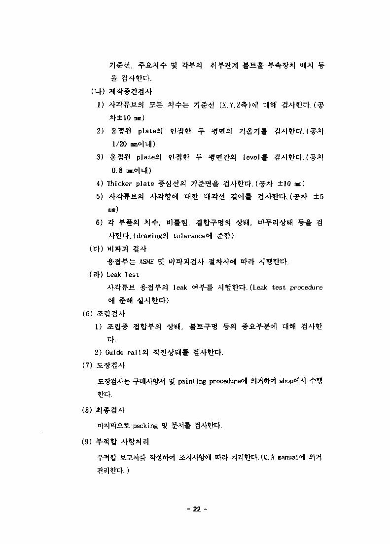
(X.Y.Z^H
*f±10 mm)
level
2)
1/20
3) -§-33 plated
0.8 mmolufl)
4) Thicker plate -
5)
mm)
6) 4 J f - ^ * 1 ^ , H | * U . ^ ^ ^ - ^ ^ ^efl, nf. (drawing^] tolerance<Hl
±10 mm)
±5
« •
-f-^ ASME 5!
Leak Test
leak test procedure
(6)
2) Guide railSj
(7)
(8)
(9)
packing
painting procedure^ ^ 7 i * H shop«H|4
(Q.A manualofl
- 22 -

(10)
(Instruction manual 9l drawing for installation (function test
procedure) H ir*1|
(11)
3 NDT
1. Leak Test
Rectangular Tube*] -g-^-f % 9^4^^ leak-i
M fi 3 5 4
(1) ^l-§-^^ 91 4 1
(2) ? | - 8 - 2 H
ARTICLE 10. APPENDIX BUBBLE TEST OF ASME SECTION v
(3) Al^
(4)
(5)
(7\)
(cf) Rectangular tube Mff*>fl
^ o l ^ j j . ^oj^-a. Af^^cf. ( o ]7m^ = t |7 l^5j 1.25«f))
(ef) Leak test -f-^Hl leak tec^- £5t>rK (577V)
(nf) *) fc 15^- ^>)^^ -g- Sfi 6 J ^ ^ i f 91 leakage
* ^ ^ 1 ^ ^ ^ ^ immersion
(Hf)
- 23 -

(4)
(6)
Leak tec-i- £ £ * H leakage iH^-fi- **<&, Ieakage7\ &§-
(7)
(8)
leak -f^i- repair welding*p.
2. Liquid Penetrant Examination Procedure^- EMR report
Bucket elevator & Rectangular tube<>j|
(1)
(2) ^^.-g-4 : KS, JIS
(3) *W%*\(7\) ti^lfl^ 4**fc 7)7jfe KSB
(4-§"7|7| SER. NO. 3355-152)
- 24 -
2) M*&&2\ ^ 3 £ # ^ W . (Shore hardness)
3)
4) 4^715] "0
5)
6)
2)
3)
4)
5)
(°F) ^ ^ 7 1 ^ : KS 51 JIS«H1
(4)
(5)
KS ? l ¥ ^
2. General Welding Procedure-^ EMR report
- 25 -

1. Rectangular Tube
(1) *W 51
Bucket elevator-g- *}
(2)
• Tech. spec. EF-E-2490-DT-101 : Rectangular tube of bucket
elevator.
• ASME : american society of Mechanical Engineer.
• AWS : American Welding Society.
• ANSI N45.2.2 : Packaging, shipping, Receiving, Storage
and Handling of Items for Nuclear Power
Plants.
{7}) €#*!•£, #^ 51 i^'H] ^ ^ f ^ 44^-^-fe ANSI N45.2.251
level. D4*<H1 Cf^cf.
(14) *|3f«a r *?1^ "inS.^. 51 shop dwg. ,
(4) Drawing
IMEF-BE-049 : Rectangular Tube Assembly.
IMEF-BE-050 : Rectangular Tube Detail Drawing.
Hm Drawing
EF-E-3000-NH-H001 : Hot Cell Arrangement General Layout.
EF-E-3000-NH-H002 : Hot Cell Arrangement Plan of Ml.
EF-E-2420-CD-H202 : First Floor framing Plan-1
(EL+77,300).
-26-
EF-E-2490-NH-H001 ~ 6 : Nuclear Drawing (Pool Liner).
EF-E-3000-NH-H221-3 : Plan of Ml Hot Cell Drawing.
(7\) Rectangular
Temporary bracing-§
(14) -J± 1 d * M Handling
1) HandlingAj^ z\ - ^
2) Fork l i f t s , handling>Mfe ^ H .
^<H1^ io~2O cm °> #<H-S-ei H
3) S . ^ 3 ^ o l S.^ tower 3.efl<y
lug<H) sling
60°
tower1) ^-^.l- S
lifting lug-i-
2) H . # Ml cell
• Craned hook
Mlej
Ml cell
base
handli
. (o)n)|
lifting
body/top^fl
*\MM Tf--
3) ^-w.7f
elevation
re-barS
4) Re-barS.
5)
6) llt*L7\
(6) Tolerance
5)^ chain block Si
location^-
fe plate
±5 nun
(14) ^ H /
—27-

20 m
(7)
(7\) level
(8)
2. Rectangular Tube & Bucket Elevator
(1) *W 51
bucket elevator^
(2)
•Tech. Spec. EF-E-1810-DT-H101 : Bucket elevator
• Tech. Spec. EF-E-2490-DT-H101 : Rectangular tube of bucket
elevator
• ASME : American Society of Mechanical Engineer
• AWS : American Welding Society
(7\)
(14)
(rf) >.e||ti^|i
5| shop drawing,
(4) j*|-g- drawing
(7\) Bucket elevator
• IMEF-BE-000
• IMEF-BE-001-12
Bucket Elevator Assembly Drawing
Bucket Elevator Sub. Assembly & Detail
Drawing
Rectangular Tube Detail Drawing• IMEF-BE-050
(uf) ^J^- Drawing
• EF-E-3000-NH-H001 : Hot Cell Arrangement General Layout
• EF-E-3000-NH-H001 : Hot Cell Arrangement Plan of Ml
-28-
(5)
EF-E-3000-NH-H001 : First Floor Framing Plan (EL+77,300
EF-E-3000-NH-H001 : Plan of Ml Cell Drawing
£ 0) Q'Qtt 3-t} & base
© Fl low block 4 base
(3) Sleeve shaft
d) Chain sprocket & chain
(5) Bucket sproket
@ Guide rail (Guide pipe)
© Bucket
Dwg. No. IMEF-BE-OOl J driving unit assembly#
wallofl >g*l^ sleeve pipe^j -f-^^d^- 7 l ^ A S
base# - M ^ ) ^ ^ £ E f f i ^ J ^ c K
Dwg. No. IMEF-BE-001^ tti]of3oi base# Ml celltflofl ^ 1 ^ -g^y
-£-§- 7 | ^ A S elevation^- ^^<H ^*l^x:>.
Coupling l l Fl low block HJH*£.©.,§. sleeveufl<H] sleeve shaft
Fl lowsprocket il bucket sprocket!- shafts]
block >H|<>[i8-fi..S. baseofl
(n\) Ml c e l H ^ J #<H1 7) ^
: 1) 7HH
sprocket ^ e ^ o f l
51 counter plateS.
2) 7}o)H
(4) Bucket
f l ^ H S 1*1 bucket
fl-«.M| liner plate
!£• bucket chain roller7}
bucket# fw.
- 2 9 -

H ) #7)^*1 ^ ^l^^l-a *J*H1- 1i*)W. (Panel, Limit switch,
(6) -a
(7)
(7\) A}4^.U.<H1 Bucket elevator7f
BANDO ^ 4 ^ ^ BDS-FT-806oil
- - 3 0 -
5 g-
1. Bucket Elevator
(1) W34\ 51
Bucket elevator!- * H , ^^l*UVl ^ ^ ^ ] ^ # *}7]
(2) ^ S ^ A - I
Tech. Spec. NO. EF-E-181O-DT-H1O1
(3) *]%%*}
(7» Bucket elevator^
block
1) Motors)
2) Breaks)
3) Limit switchS)
4) Bucket elevatorS) speed# *ij lt:f. (speed tolerance ±10
(4) ^-t\ .^Al^^- ^AltfcUrated load)
1) MotorS)
2) Breaks)
3) Limit switchS)
4) Bucket elevatorS) speed# *fl3. >t:)-. (speed tolerance ±10
(Uf) s};g : spec. ^ ^ ^ ^ i drawing^] i
(4) Tfl^^Hl
Stop watch, Current meter, Volt meter,
(5) 3471^
^ ^ 0o> 6fl £tfcK (Test Report
(6)
- 3 1 -

n\ 6 g-
1. "1-Ton Bucket Elevator" EMR.
2. "Rectangular tube" EMR.
3. ±^7] $] "2:4*1)A|<gA|^ ^ - i " , KAERI/RR-880/89,
1989.
4. i^^7) ^ " 3 : 4 ^ 4 ^ 4 ^ ^^" , KAERI II/PR-3/90,
1990.
5. ^A^flA|^A]^ ^.7)^.^711^. ^ 7 ] ^ ^ l ^ H "IMEF-RC-1" , 1997.
6. "KS 51 JIS ^-"a^-^" .
7. ^-8-^*1 "^4^114^4^ ^ 1 ^ M " , ^^•^4^ < a j ?-^ . 1997.8.
- 3 2 -

COCO
1&
8CO
n
PICD
CU
O- J
COCOCO
|
on

CO
utifiCO
Q .CD
33
O
ICD
CD
o
. ' ' J I WOO .....

COeni
CO
3'
05COCD
mCD
?..£k2Z222_
A
ft
*
1»
AS6
7S9«j
n121314
OSIVIN&IMT ASiTl
SEARED MOTOR0CA« CCUPUNOR5. SPHOCKET.A
SLIMIT SWITCHSHArr .A
SHAFT.S
WAFT SUEVEBEAR1NO '•"•"41'n
us ?PBOCK£T.C
US SPSOCKEID" f SPSOCrfT
KAPINC F I LWK-«
—
J«5CSS«1Sill
-
.
sa>x —5«5CS«5tiSJO-
-
1
1
1
22111
31121
1
1
1S8112
0.61«
83.664.6
16.84.4
11.6394.7
10.1
4?7.«
1 4
ns<o>J4T
RS4O«13T
»<r<ic-ooiUCO213
RS100l>»T
sswo»2eT
UCP216IUCP21J
•M>- LOU2 E*-M- ;
FIRST ISSUE
KOREA ATOMIC ENERGYRESEARCH INSTITUTE
( | ) BANDO MACHINERY CO., LTD.
Vie,
RWMP - (M£F
jTON_
ORIVINO UNIT ASSEMBLY
EF-76OO-M-K02S
/4t\ r is&^ I—J

I
CO
u
oQ -CD
33
CO
1- 5
03
SECT A - A
L-8!
THAY DETAIL
©
\ 1^'FChTt TRAY ] - I |
PRE CISJT I55UE
KOREA ATOMIC ENERGYRESEARCH INSTITUTE
(§ ) BANDO MACHINERY CO., LTD.
|
RAIL 5UPPORT 4 TRAY OETAIL
EF-76OO-M-KO25
IMEF-SE-O'3

I
<M4
Ma™tn
o»
a.
o
CDQQCOffl
CD
5
O
KOREA ATOMIC ENERGYRESEARCH INSTITUTE
g ) BANDO MACHINERY CO., LTD.

M
CO(DCD
fiCD
O
oaECen
O
I
o
CO
o(0
mCD
rO
Hsu^
TH£
-i - ^ ci]3M-l CELL
T^ ^ / ' i i
TOO
, ^ < "
© u ^
•~1
i
i i- i
_ ?
- :
-a
-6
,2 i
i -2
BEAflkrtC 3A5E
t U « J30'
Kt2«iOO '
t.9 • 66 •'
t 9 • ao >
30
i 'Z> T "60
LINES P
«. 2 ' 6 0 "
t 3 "80 >
t! '»•
LATE
00
00
00
*^ 104 1 '•'
]
[
1I
V Ie i
V'A
e
' 1
9
t" m - l Si
I '28 :so ! i79
« i l •
6 9 ;
06 !
- 1 |H« .«< ' . .O ' '
! ' 5 1J i ;
•5 1 1' ! I 1
/ViA
ZSTTA
AEE
"I A 3 D U 1 L i
" « , r t i ; r C 1 I>M" W B Q -IQ^'I «WQC Vflfr
TSB^ffiwioc i - - - ' " - ^ " - " - ^ ^
ArrJ4i*>,a»pti
£ KOREA ATOMIC ENERGYS" RESEARCH INSTITUTE
vS/
IMEF-8E-0H
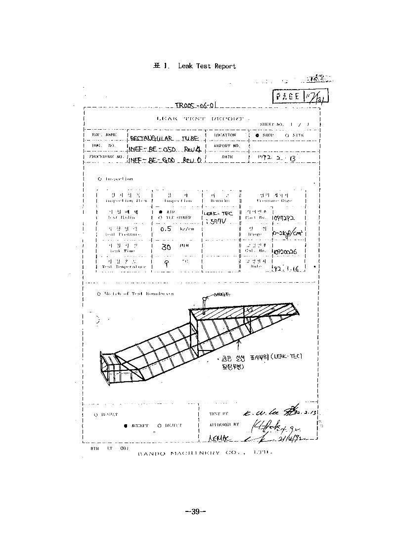
S. 1. Leak Test Report
-^6r51
! . ! • : AK •IT'S'!1 mz\ 'OUTSIII'KT NO. I / I
K NO.i
D M K
O IHK|.I.M:I inn
1 •>-• = !•
•1| . - s
•1T . - : : l
•1
IV
•1Tt ••; 1
M '. 1 1 .- . _
k.i "ifl.-l.l
• ; l - ; lI'l .••-.
\l '1: 1 T i
'1 *
•••IU|M-
I '•;i l I I . - in
- . .
i n
.•1
" • " • '
• 1
ii«-
I :i 1 Ml i -
I n s , .. _ . . . .
• All 'n -nil
0.5"
30
<-,T
i 1 ion
I r i":". . .K|!/<'iu
M I N
- i :
"1ll.inni !(•;
;.snn\/...
... IfIIII
-- IIIIII
- IIIIII
IIII
IIII
' i "iI'm 1
','!If'li
i.1 ' '
<:.-ii.
•„. ; ;
Hi
•;lI'l ••:
V1 fM.i.
?l
H o .
•ri 41 o
1 1Mil "
- -r110"!_. | _
. .\r~}i! „ -i T -
•1(,
1
n
•'•i i
<$/<^ i
t5CO6 I
1 if '* * 1 V I
0 KK-.-l i-li nl' T'-KI IIMIIIIII.-II i' :•
1
ACCIil'T O Ill-MRM'
HTH I.T 001P . A N D O M A C I M N K K V C X > . , I .MM) .
-39-
REPORT OF LIQUID PENETRANT TESTING
EXAMINED BY
APPROVED BY
LEVEL DATE
LEVEL JB
THIRO PARTY INSPECTOR
CEC- p-0 ' CHOEUN ENGINEERING CO., LTD.
- 4 0 -

fi 3. Report of Inspection
» • •
REPORT OF INSPECTION
I "I V- <l '4 I - I - 7\
- 4 1

S. 4. Report of Inspection
REPORT OF INSPECTION
SIIKKT NO:Q. A-C-
W/O NO.
ITEM
OWC, NO.
MATF.UIAI.
SKHTCII:
R.U)HP ~
Q TVI (ST)
IN.SI'KCTHK
DATI-J
OWNKU
DATK
so.- a. //__
CIII-XKI'O.SIIKIN
I )\vc;DIMI'.NSKIN
TOl.KliANCI-".
DKV1AIION
DHVIAIION
DKVIATION
DEVIATION
±10
•H-S
JiX). liCL
L
.tLQ
A
ASQ
±1CL
N.K
,-rti.S
, 456
±10
Hi;MAIiKS.
!•'} V. ' I '1 I " I - '-> ) I'.ANIK) MAfiMNI-.llY CO.. I.TH.
- 4 2 -

5. Report of Inspection
P A G E
REPORT OF INSPECTION
NIIKKT NO:Q. A - O
W/O NO.
IIT:M
DWG NO.
MATKHIAI.
SKKTCII.
sr ix ron
Q. A
UATK
OWNI-.K
MM i:
(I/NII :M/M)
C I I I - X K
I'OSl-IION
invi;DIMENSION
IOI.I KANfl-.
DIAIAI ION
I I O N
DKVIATION
•t4-Q tl-D
-D-0
-1.0
-K
ti-s:
t\'(\
KI.MAKKS.
OIU-
C j l s 'I 'I I - I - 'i I'.AMlii MAflllNCKV CO.. I.IIJ.
- 4 3 -

S. 6. ^-J±
eoo
3500
4650
GCO J
UNIT '-
- RESULT/A:AOCEPT ' R : R £ J E C T
A
D
C
D
14.4 R3INT
1K2 POINT
i
I
-fbir
-/r
z 3 RESULT
Kft1?
K
REMARK
V
-vg/ QrQ-.199 > . / .
199
- 4 4 -
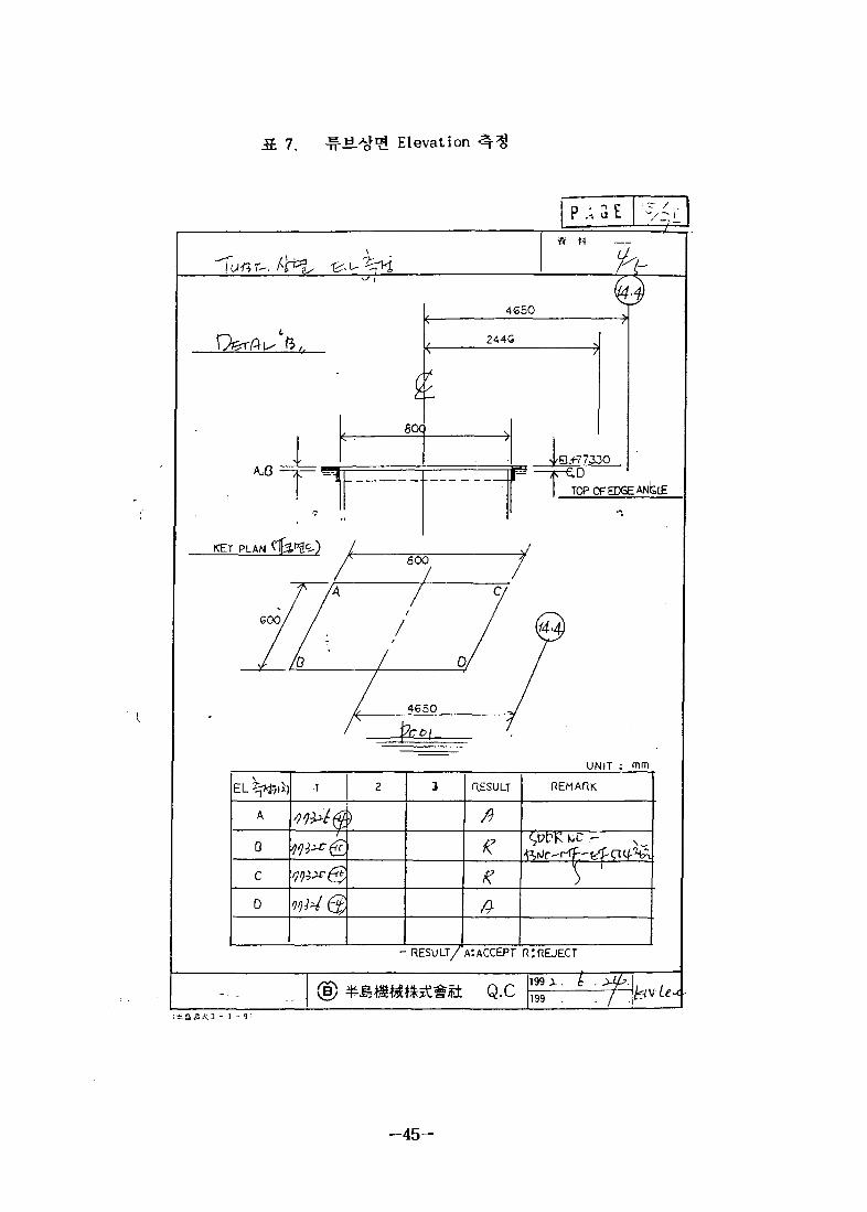
7 ^ t i . ^ o ^ Elevation
I n iP A G E
*£?- h-
O&rAl^ ft,.
A,B
KEY PLAN
6O<
T600
GOO
/
/
/
4C50Q
244G
JEL+77300D
TOP CF EDGE ANhlE
0/
4650r^ 'co\
UNIT
EL ^ i7 i i )
A
D
C
D
1 2
)
3 RESULT
ft
%
K
REMARK
^tJC^ r-ff-- fA- CX I f "HA
- RESULT/"A:ACCEPT R:REJECT
199 X. I .(B) Q.C 199 . . /
- 4 5 -

S. 8. w.*fg 71 #7]
P A G E |
UNIT ; mm
"IT:*?.
U
L
1 2 3 '-RESULT
A/?
REMARK
-nESUU/A:AGCEPT R: REJECT
(B) Q.C199 > . _!99
—46-

3. 9. ^«.
4
1 2 3 RESULT
UNIT
>
(
: mm
- R E S U L T ' / A : ACCEPT. R: REJETC
(S) Q.C1 9 9 ^ .
199
- 4 7 -

MATERIALS SPECIFICATION
SDDR BNO-MF-EFSOl BUCKET ELEVATOR AND RECTANGULAR TUBE
00
NO.
1
2
3
4
TITLE
STRUCTURAL STEEL
STAINLESS STEEL
STAINLESS STEEL
STAINLESS STEEL
TECH'
SPECIFICATION
ASTH
A36
ASTM
A240
TYPE 304
ASTM
A24O
TYPE 304L
ASTM
A479
TYPE 304L
BANDO'S PROPOSAL
JIS
G3101 : SS41
KS. D37O5
JIS G43O4
ASTM
A24O
TYPE 304L
IE. D3705
STS. 304
U S E
PLATES. REINFORCING ANGLE. ETC.
DUCKET. ROLLER CHAINS. SHAFT.
GUIDE ROLLER. SUPPORT. ETC.
PLATE. THICKER PLATE. BACK STRIP.
CORNER 4 EDGE ANGLE
REMARKS
FOR STRUCTURE
FOR ELEVATOR
FOR TUBE
FOR TU
m
$
I
-1
\
r
a
•go
§

11. ^Ji
'S
i '
[ M E F
I „ MEF-BE-OCO REV.j
4 DATE : 1992- 6-*l.\
4. •£• -^ ± H * '
04-4 ; I j ^ r f
,. 4SCb
'"1 I
1 !
J,
1 .ol
SI?
1 10O
ix y
V-iJ>ISOi
1
VJ
. i
j
o! ; —
" i ! M l CELL '
5. TUBE LOCATION i ELEVATOR *-32 C -/
LOCATION : -y- =!"
b) ELEVATOR :FLANGE
"ife? ; / H'^ —
\A (ZAtXIf-'J =*"2
- 4 9 -

12. Bucket Elevator Rail
BUCKET ELEVATOR RAIL
)
i
CHECK POIOT
1
2
3
4
5
6
7
8
# 2 | CHECK
SHEET OF
§PM\ HU 77300
^>?1*} CHECK
390
387
390
389
390
393
393
393
Z*\ CHECK
389
388
389
389
390
392
393
393
\J*S < W ) SUiVEY LOCATION
3*} CHECK
389
387
388
389
390
392
392
393
- 5 0 -

S: 13. Bucket Elevator Rail
BUCKET ELEVATOR RAIL CHECK
SHEET OF
US.*}
© NO] SURVEY UXAT10N
CHECK POINT
A
B
C
D
A'
B1
C'
D'
1*} CHECK
0
• 3
• 6
• 9
0
0
0
0
2X\ CHECK
0
• 3
• 6
* 9
0
0
0
0
3*> CHECK
0
• 3
• 6
• 9
0
0
0
0
— 5 1 -
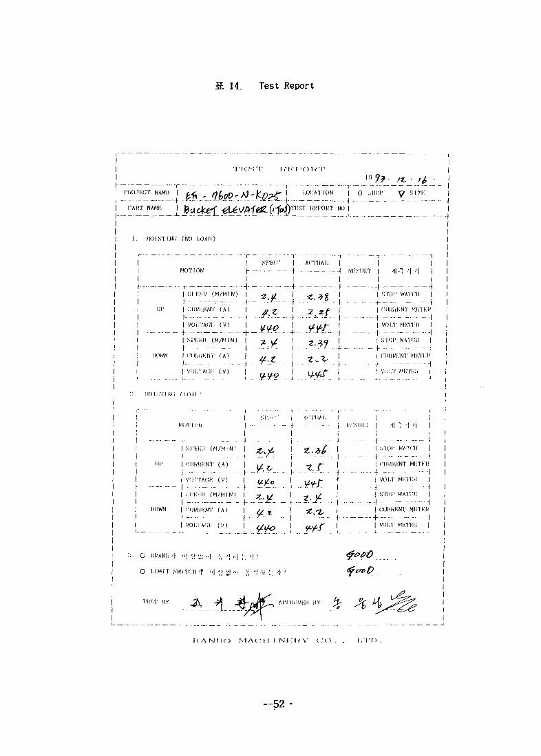
14. Test Report
IVKl-'OW'V
i
-\- — — -- — -
AM]-; II __
I LOCATION I O o l id '
I'I'UST RKP'ONT NO |
y SITK i___ I
I i . iioisTrw; (MO UJAD)
Uf
|
MOTION
| SPKKI) (M/MIN)
I C I I K W K N T ( A )| ..
I V O I . T A W : ( v )
i rI srwv I ACTUALI I
« 2 Z&
I
I SI'KKI) (M/MIN) | - j , , /r .. 4 ...... ^ri--
IIOWN | C H W H N T ( A ) | „ g
l~' ~ " f| V O l . T A C I i ( V ) |
I INK.SUI.T | 4 •") '\ ' | |
I I+ \| STOI' WATCH |
- • 4 \| rilKUIiNT MI"l'lilV4 1I VOI.T MRTIW I
+ 1
j STOP WATCH |
| CIIKI/ICNT MHTIW
! VOI.T W:\-VM I_ ; . . . _ . . .J
I I O I S T I N i ; ( I.OAI '•
DOWN
MI lT l i ' l lI SI I'."':" | ACTUAL | | I
| \ i 1,-KSUI.T | -1 * 1 ' | I
I I
! SI 'Ki i l l ( M / M I N ) |. . . . . |.
("IIKKICNT ( A ) |
V O I . T A G K ( V ) | < / y £ )
(M/MIN) |
fIvNT (A )
I V O l . T A C h : ( V )__.L _ I _. ±
6• • - I - \
I STOP WATCH I
• - f - \! CMHIUiNT MI'TKU
- - - I If | VOI.T MI-TUW |
I - t - 1| | STOP WATCH I
I f II I CUHHKNT MKTKH
| VOI.T MKTI'M.' Ij j
O L I M I T .SWITCH ' f r,\ \\ ',jl ,,| v <| ,v| ..;• r\ ?
TliST IIV AI'I 'IIOVICIP I1Y
HAN1K) M A C I I I N i : U Y C.- O . , I , ' I' I) .
—52-

: rev. 2
1998. 6.
- 5 3 •
1.
fe
2.
)^fe 25X25X150 cm
63° S-^ ufl
MI
Ml
3.
- EF-E-1810-DT-H101
- 1^- tH^! <ae)»Wel EMR
- Rectangular Tube EMR
4.
4.
£ •§•
- 5 4 -
4.2
4.4
4.5
BE : Basket Elevator
5.
- 7) of
— 5 5 -

(12-D'ofl
6.
6.1
6. 2 Ml
- MI
Rear & Roof door
6. 3
on
- M l ttr ^ S # «-| ofl l ^ ^ 1 on
run
HSU Up run ^ 5
—56-
Bucket up position fl57>
Up run ^ f
Down run ^ ^ ^ i H3M F ^ } f e |
^ | 1 U Down run HH
1 Bucket down position
r u n $*?} ^ -
7.
7.1
m ^^r ?H^a7} # Hf^<i ^ I3£ | ^ HI^H 7fWf# Lid
ToolS.
---57-

7.2
Ml
- Ml
- 'Up run'
position'
(Up
up position'^S
8.
8.
. ( '*W Down
Down
. ( 'UP run' 1357}
9.
9.
^ o.
-58-

9.2
10.
(EF-IM-0009)
- 5 9 -
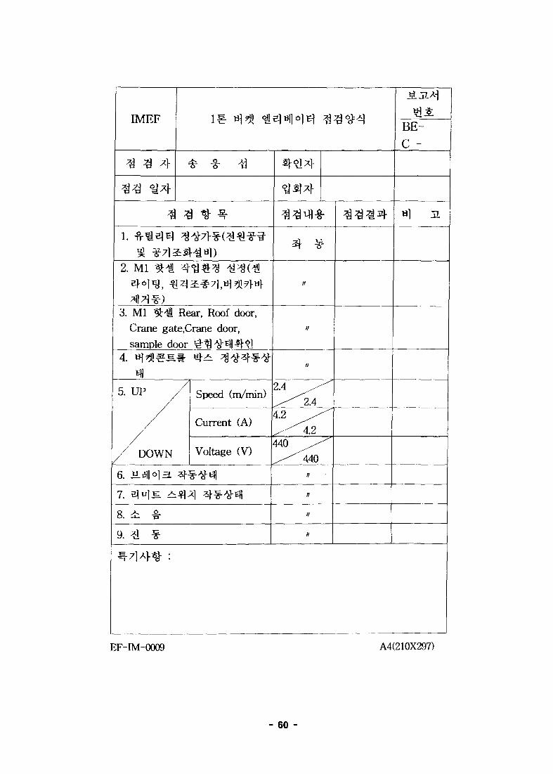
IMEF
3 Q *\
% 3 *} ^
2. Ml ^ ^ 4^$^ ^^(€
3. Ml M Rear, Roof door,Crane gate.Crane door,sample door ^^^-Efl^-^1
n5. UP
/
/ DOWN
/ Speed (m/min)
Current (A)
Voltage (V)
6. J±3M£L ^^^3-Ell
7. elulE ^f l*! 4 -4>Efl
8. i >
9. ^ *
//
/r
//
2.4 ^ ^
4.2 ^ ^ "
440 ^ ^ ^z - ^ 4 4 0
BE-
C -
EF-IM-0009 A4(210X297)
- 60 -
INIS
KAERI/TR-1301/99
(AR.TR-§•
1999. 4.
62 P. -H-( O ),•¥-( ) 21 x 29.7 Cm
2: 3-
(3x6x10
25x25x150 cm
Ml-JHii/r 71^
u.( Guide Rail. •?•& ^ l ^
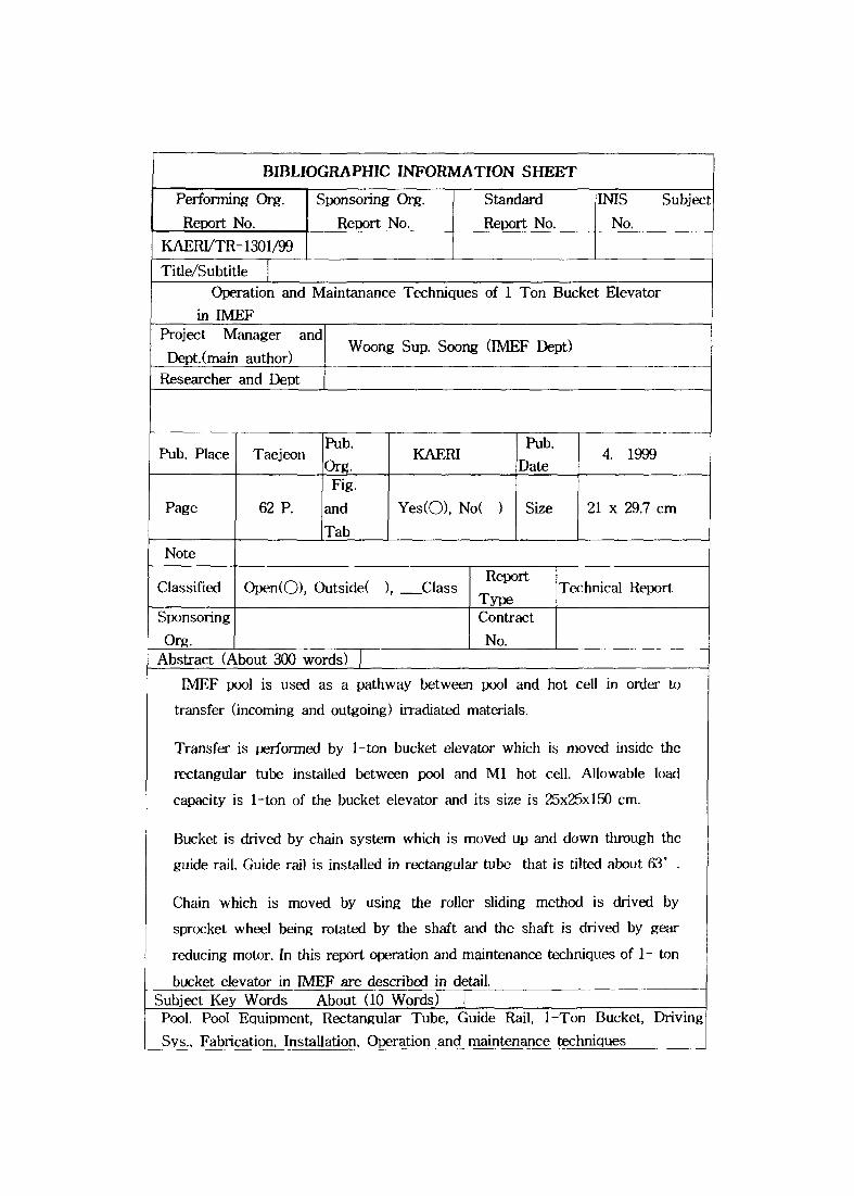
BIBLIOGRAPHIC INFORMATION SHEET
Performing Org.
Report No.
Sponsoring Org.
Report No.
Standard
Report No.
IMS Subjec;
No.KAERI/TR-1301/99
Title/Subtitle
Operation and Maintenance Techniques of 1 Ton Bucket Elevator
in IMEFProject Manager and
Dept.(main author)Researcher and Dept
Woong Sup. Soong (IMEF Dept)
Pub. Place TaejeonPub.
Org.KAERI
Pub.
Date4. 1999
Page 62 P.
Fig.
and
Tab
Yes(O), No( ) Size 21 x 29.7 cm
Note
Classified Open(O), Outside( ), ClassReport
TypeTechnical Report
Sponsoring
Org.
Contract
No.Abstract (About 300 words)
IMEF pool is used as a pathway between pool and hot cell in order to
transfer (incoming and outgoing) irradiated materials.
Transfer is performed by 1-ton bucket elevator which is moved inside the
rectangular tube installed between pool and Ml hot cell. Allowable load
capacity is 1-ton of the bucket elevator and its size is 25x25x150 cm.
Bucket is drived by chain system which is moved up and down through the
guide rail. Guide rail is installed in rectangular tube that is tilted about 63° .
Chain which is moved by using the roller sliding method is drived by
sprocket wheel being rotated by the shaft and the shaft is drived by gear
reducing motor. In this report operation and maintenance techniques of 1- ton
bucket elevator in IMEF are described in detail.Subject Key Words About (10 Words)Pool. Pool Equipment, Rectangular Tube, Guide Rail, 1-Ton Bucket, Driving
Sys., Fabrication, Installation, Operation and maintenance techniques