Embed Size (px)
Citation preview

IAEA-TECDOC-1532
Operation and Maintenance ofSpent Fuel Storage and
Transportation Casks/Containers
January 2007

IAEA-TECDOC-1532
Operation and Maintenance ofSpent Fuel Storage and
Transportation Casks/Containers
January 2007

The originating Section of this publication in the IAEA was:
Nuclear Fuel Cycle and Materials Section International Atomic Energy Agency
Wagramer Strasse 5 P.O. Box 100
A-1400 Vienna, Austria
OPERATION AND MAINTENANCE OF SPENT FUEL STORAGE AND TRANSPORTATION CASKS/CONTAINERS
IAEA, VIENNA, 2007 IAEA-TECDOC-1532 ISBN 92–0–115006–7
ISSN 1011–4289 © IAEA, 2007
Printed by the IAEA in Austria January 2007

FOREWORD
While casks have been an essential part of the nuclear industry’s transportation of radioactive materials for decades, that role has significantly expanded in recent years, particularly with respect to the dry storage of spent fuel for plant sites around the world. While the majority of the world’s spent fuel is still kept in the classic water pool, trends show that most new storage systems are built to take advantage of the practical passive and modular features of casks/containers as an effective option for short and long term storage of spent fuel.
Spent nuclear fuel has been stored safely in pools or dry systems for decades in over 30 countries. This international storage tradition has resulted in a vast technical record, as well as an appropriate understanding of the operational practices that are beneficial for spent fuel storage. In addition to the historic study of spent fuel transportation, industrial experience has also been accumulating in the use of casks/containers for storage, both with dedicated or dual-purposes, in an increasing number of Member States. Valuable knowledge in cask/container operation and maintenance is also available from spent fuel storage sites around the world, combined with relevant regulatory experience. In view of the expanding need for casks/containers in a growing number of Member States, for both transporting and storing spent fuel, combined common technical knowledge found in both transportation casks/containers and spent fuel storage casks/containers can provide for improved planning and implementation in future cask use projects. It may also help build public confidence, which has become a crucial issue to most projects. There are several international resources providing technical information on transportation and storage casks, as represented by PATRAM (International Symposium on the Packaging and Transport of Radioactive Materials) and a few meetings organized by the IAEA. However, only a few publications on the subject exist, despite the rapidly increasing use of casks/containers in spent fuel storage around the world. The only referential IAEA publication is IAEA-TECDOC-1081 (1999), Spent Fuel Storage and Transport Cask Decontamination and Modification, which is a publication focused on the decontamination of transportation casks/containers. Some important measures have been developed for the contamination-free operation of casks/containers in the past several years in Europe, thus enriching the knowledge base for cask/container operation and maintenance for spent fuel storage, as well. This TECDOC is intended to provide a comprehensive guidance on the major issues to be considered for cask/container operation and maintenance associated with spent fuel storage from knowledge gathered from industrial practices and research results associated with the use of cask/containers for spent fuel transportation and storage. The contributions from various experts to this TECDOC are highly appreciated. The IAEA officer responsible for this publication was J.S. Lee of the Division of Nuclear Fuel Cycle and Waste Technology.

EDITORIAL NOTE
The papers in these proceedings are reproduced as submitted by the authors and have not undergone rigorous editorial review by the IAEA.
The views expressed do not necessarily reflect those of the IAEA, the governments of the nominating Member States or the nominating organizations.
The use of particular designations of countries or territories does not imply any judgement by the publisher, the IAEA, as to the legal status of such countries or territories, of their authorities and institutions or of the delimitation of their boundaries.
The mention of names of specific companies or products (whether or not indicated as registered) does not imply any intention to infringe proprietary rights, nor should it be construed as an endorsement or recommendation on the part of the IAEA.
The authors are responsible for having obtained the necessary permission for the IAEA to reproduce, translate or use material from sources already protected by copyrights.

CONTENTS
1. INTRODUCTION ............................................................................................................ 1
1.1. Overview on spent fuel management ................................................................. 1 1.2. Global requirements for spent fuel storage......................................................... 1 1.3. Spent fuel storage options and trends ................................................................. 2 1.4. Spent fuel transportation..................................................................................... 3 1.5. Scope of the TECDOC ....................................................................................... 3
2. CASK/CONTAINER TECHNOLOGIES FOR SPENT FUEL MANAGEMENT ......... 3
2.1. Spent fuel characteristics .................................................................................... 4 2.1.1. Types of commercial spent fuel.............................................................. 4 2.1.2. Spent fuel burnup.................................................................................... 5
2.2. Review of technical options for spent fuel storage............................................. 5 2.2.1. Removal of decay heat............................................................................ 6 2.2.2. Mobility of storage systems.................................................................... 6 2.2.3. Modularity aspect ................................................................................... 8 2.2.4. Commercial systems ............................................................................... 8 2.2.5. Concepts in development...................................................................... 10
2.3. Casks operation and maintenance for spent fuel transportation ....................... 12 2.3.1. Spent fuel transport operation............................................................... 12 2.3.2. Transportation casks ............................................................................. 13
3. SUMMARY OF REQUIREMENTS FOR CASK/CONTAINER OPERATION AND MAINTENANCE ................................................................................................. 13
3.1. Requirements for storage systems .................................................................... 14 3.1.1. General.................................................................................................. 14 3.1.2. Technical recommendations for storage ............................................... 16 3.1.3. Acceptance tests and monitoring .......................................................... 17 3.1.4. Physical protection and safeguards....................................................... 19 3.1.5. Quality assurance.................................................................................. 19
3.2. Transportation................................................................................................... 19 3.2.1. General.................................................................................................. 20 3.2.2. Technical............................................................................................... 21 3.2.3. Acceptance tests, maintenance programme and monitoring ................ 22 3.2.4. Physical protection................................................................................ 24 3.2.5. Quality assurance.................................................................................. 24
4. GENERAL DESCRIPTION OF OPERATION AND MAINTENANCE (“O&M”) PROCEDURES .............................................................................................................. 25
4.1. Commissioning................................................................................................. 25 4.2. Operation .......................................................................................................... 26
4.2.1. Preparation for loading ......................................................................... 26 4.2.2. Loading of the fuel assemblies ............................................................. 27 4.2.3. Preparation for transfer/shipment ......................................................... 27 4.2.4. Transfer/shipment ................................................................................. 28 4.2.5. Preparation for storage.......................................................................... 28
4.3. Maintenance...................................................................................................... 29 4.3.1. Transport ............................................................................................... 29 4.3.2. Storage .................................................................................................. 29

4.4. Record keeping ................................................................................................. 29
5. FACTORS AFFECTING OPERATION AND MAINTENANCE – EXPERIENCE AND LESSONS LEARNED ................................................................ 30
5.1. System design impacts...................................................................................... 30 5.1.1. Operability considerations .................................................................... 31 5.1.2. Maintainability considerations.............................................................. 32 5.1.3. Ancillary systems and infrastructure .................................................... 32 5.1.4. Facility (modification) .......................................................................... 32
5.2. Operational experiences ................................................................................... 33 5.2.1. Schedule................................................................................................ 33 5.2.2. Technical............................................................................................... 33 5.2.3. Human factors....................................................................................... 34
5.3. Exposure control............................................................................................... 34 5.3.1. Radiation............................................................................................... 34 5.3.2. Hazardous materials and situations....................................................... 35
5.4. Specific examples ............................................................................................. 35 5.4.1. Technical issues .................................................................................... 35 5.4.2. Handling damage .................................................................................. 35 5.4.3. Pre-installation check............................................................................ 26
6. FUTURE ISSUES........................................................................................................... 37
6.1. Cask/container development and design .......................................................... 37 6.1.1. Trend to larger cask .............................................................................. 37 6.1.2. Trend to high burnup (HBU) and mixed oxide (MOX) fuel use .......... 37
6.2. Systems design ................................................................................................. 38 6.2.1. Multi-purpose systems.......................................................................... 38 6.2.2. Dose reduction measures ...................................................................... 40
6.3. Shipping to further destinations........................................................................ 41 6.3.1. Cask/container transfer between facilities ............................................ 41 6.3.2. Maintenance requirements before transportation ................................. 42 6.3.3. Preparation for transport ....................................................................... 42
6.4. Decommissioning ............................................................................................. 43 6.4.1. Casks/containers ................................................................................... 43 6.4.2. Facilities................................................................................................ 44
6.5. Other issues....................................................................................................... 44 6.5.1. Licensing issues .................................................................................... 44 6.5.2. Global acceptance ................................................................................. 45 6.5.3. Country policy changes ........................................................................ 46 6.5.4. Business aspects and economics........................................................... 46
7. CONCLUSIONS ............................................................................................................ 46
7.1. Status and trends in cask/container storage ...................................................... 46 7.1.1. Dry storage............................................................................................ 47 7.1.2. Technical options .................................................................................. 47
7.2. Cask/container operation and maintenance ...................................................... 47 7.2.1. AR operations ....................................................................................... 48 7.2.2. Cask/container operation and maintenance .......................................... 48
7.3. Future issues ..................................................................................................... 48 7.3.1. External factors ..................................................................................... 48

7.3.2. Internal factors ...................................................................................... 49 7.3.3. International services ............................................................................ 49
APPENDIX I: COMMERCIAL CASKS FOR SPENT FUEL STORAGE ............................ 51
APPENDIX II: COMMERCIAL CASKS FOR SPENT FUEL TRANSPORT...................... 55
REFERENCES......................................................................................................................... 57
COUNTRY REPORTS
Description of spent fuel transport containers and dry storage in China ................................. 61 J. Han
Interim spent fuel storage facility of Czech Republic.............................................................. 67 S. Kuba
Country report France .............................................................................................................. 70 M. Hartenstein
German storage facilities for loaded transport and storage casks ............................................ 75 K. Dreesen
Operation and maintenance of spent fuel transport casks in the Republic of Korea ............... 85 Jeon Hoe Ku
Operating experience for dry spent fuel storage facility with CASTOR-RBMK and CONSTOR-RBMK containers ...................................................... 90 S. Shishkin
Current status and issues related to transportation of hazardous nuclear materials in the Russian Federation.................................................................................................... 95 Yu.V. Kozlov, Yu.A. Kosarev, A.L. Lazarev, V.D. Safutin, N.S. Tikhonov, A.I. Tokarenko
Current situation of spent fuel storage and perspectives in Spain.......................................... 105 E. Rubio, M. Garcia
Transport and storage of spent nuclear fuel in Sweden ......................................................... 109 A. Persson
Maintenance policies, experience and facilities employed by BNFL for its spent fuel transport flask fleet........................................................................................... 112 G. Jones, D. McWilliam
CONTRIBUTORS TO DRAFTING AND REVIEW ........................................................... 121


1. INTRODUCTION
Storage and transportation of spent fuel have become the major operations that provide platforms for future options in the backend of the nuclear fuel cycle to be adopted by Member States producing nuclear power. With growing anticipation for sustainable utilization of nuclear energy in the long term future, the importance of safe and efficient management of spent fuel will likely continue to be amplified in the future. 1.1. Overview on spent fuel management
The options for spent fuel management chosen by each Member State can be generally categorized into three groups:
• those that pursue a closed cycle by reprocessing spent fuel and recycling MOX fuel,
• those committed to the direct disposal of spent fuel,
• those who have postponed the decision to be made later (the “wait and see” position).
Although the preponderant reactor type currently used for the majority of commercial nuclear power is the light water reactor (LWR), there are several other reactor types in commercial use, such as heavy water reactor (HWR), gas cooled reactor (GCR), boiling water cooled graphite moderated pressure tube type of reactor (RBMK). Globally, the bulk amount of reprocessed spent fuel is comprised of LWR, Magnox and advanced gas reactor (AGR) types. The other spent fuels are mostly stored.
Discharged spent fuel is typically kept in a temporary cooling pond at the reactor (AR), which may be followed by an storage for a time span of several decades (perhaps even several centuries) before it is reprocessed or, after conditioning, finally disposed of in geological formations. Since a large number of Member States have decided not to reprocess and recycle their spent fuel, and because of a currently limited reprocessing capacity, the disposal option has gained popularity over the years in Member States. However, changing perceptions and circumstances in global energy and environmental concerns, as observed recently, may direct the future trend onto a different path [1].
1.2. Global requirements for spent fuel storage
Over 10 000 metric tons of heavy metal (tHM) is unloaded from global reactors each year, with annual discharges increasing to ~11,500 tHM by 2010. Since less than one third is reprocessed, about 8 000 tHM/year on average will need to be placed into storage facilities. At the end of 2004, the total amount of spent fuel generated worldwide was about 276 000 tHM of which 90 000 tHM were reprocessed. The remaining 186 000 tHM of spent fuel are presently being stored in AR and away-from-reactor (AFR) storage. About two-thirds of this amount is stored in AR pools, with the remainder stored in AFR wet and dry storage facilities. Projections indicate that the cumulative amount generated in the world by the year 2010 may surpass 340 000 tHM, and by the year 2020, it could surpass 445 000 tHM (see Fig.1) [3].
1

0
50
100
150
200
250
300
350
400
450
500
1990 1995 2000 2005 2010 2015 2020
Year
t HM
Discharged
Reprocessed
Stored (including storage for reprocessing)
Figure 1. Global trends in spent fuel management. Projection further beyond these dates will depend on the assumptions made about global trends in nuclear power generation in the future. The actual amount of spent fuel to be generated in the future, however, is subject to some contingencies. An important factor to be taken into account is the current trend toward higher burnup, driven mainly by economic incentive in the competitive power market, which will result in less spent fuel arising for a given period of power production. By contrast, the current initiatives in some countries to extend the licensed plant lifetime will increase the global amount of spent fuel. The increasing use of MOX fuel in some countries will also result in some impacts on spent fuel projections. The accumulation of spent fuel inventory to be stored is likely to continue for the foreseeable future as more countries decide to stop reprocessing or to phase out the nuclear energy option. It may, however, begin to diminish when planned repositories are built and accept spent fuel from storage. For the time being, though, national programmes charged with constructing these repositories are experiencing delays due to various problems, such as siting. Therefore, it is unlikely, that there will be any actual inventory leveling, much less decrease, in the near future. Given the current status, the most imminent service needed worldwide for spent fuel management is the supply of sufficient and prolonged storage capacity for the future spent fuel inventory arising from both the continued operation of nuclear power plants and from the removal of fuel in preparation for plant decommissioning [4]. 1.3. Spent fuel storage options and trends A variety of wet and dry storage facilities are operating around the world with bulk amounts of spent fuel still stored in AR pools. However, a review of spent fuel storage facilities implemented during the last decade shows that the storage in a dry environment is becoming a prominent alternative, especially for newly built AFR facilities. More than 18 000 tHM of spent fuel is already stored worldwide in dry storage facilities, which is comparable to that of pool type AFR storage facilities.
2

In terms of AFR storage, dry storage under inert conditions has become the preferred option, given the long term advantages it offers, such as its passive operational features. Among the dry storage facilities, cask/container type (vs. vault type) has gained popularity with many users, mainly because of its improved modularity feature, which is advantageous for incrementally expanding storage capacities, as needed, thereby minimizing capital outlay. 1.4. Spent fuel transportation
Spent fuel transportation has long been established as an important part of the industrial activities in the backend of the nuclear fuel cycle, especially for the reprocessing industry. The majority of spent fuel transported in the past has been spent fuel shipped from an AR pool to an AFR pool at a reprocessing plant. Throughout the countries, several companies have been developed for providing such transportation service, operating a number of spent fuel transportation casks that have been licensed in compliance with national and international regulations. However, as the demand for additional spent fuel storage in AFR facilities began increasing in the 1980s, cask technology has begun to be applied in the dry storage and transport service for spent fuel. This has resulted in the development of casks for dual-purpose service (licensed for both storage and transport), and has also provided the basis for development of concrete based, canister-type systems that were originally developed for storage-only uses, but are now licensed for dual-purpose applications, as well.
1.5. Scope of the TECDOC This publication is intended to provide information on the aspects of operation and maintenance associated with spent fuel storage and transportation casks and containers, with the intention to serve as a source of collective information from the accumulated industrial experiences around the world. Starting with the statistics of spent fuel management, it gives a review of the technical options and trends in cask development and applications with a focus on storage. It also gives a review of the regulatory bases being applied in the relevant areas, followed by operation and maintenance (O&M)1 procedures and factors to be considered, and by lessons learned from previous experience. The TECDOC concludes with long term considerations.
2. CASK/CONTAINER TECHNOLOGIES FOR SPENT FUEL MANAGEMENT
The prominent role played by casks in providing transportation services to the reprocessing industry is now being extended into the storage function at an increasing number of AFR storage facilities around the world. For several decades now, large amounts of spent fuel have successfully been transported from reactor sites to reprocessing plants, via over-land and water modes, using specialized vehicles. The technologies initially developed from transportation casks have been scaled up to larger sized metal casks and are widely applied to spent fuel storage facilities at many AFR sites [5].
1 The terminology, “O&M”, will appear in a number of locations in this TECDOC.
3

In response to the fast growing demand for spent fuel storage, a number of concrete cask technologies have been developed as an alternative to metal casks, making use of more economic and flexible canister-based options. The transportability of the canister/container led to a development of the multi-purpose canister/container concept, which requires that a compatibility with a disposal package be developed in order to directly dispose of spent fuel. There are also important issues associated with the long term storage of spent fuel, namely, the integrity of the spent fuel and its associated requirement for containment and monitoring until its retrieval. More recently, these issues have been compounded with security and physical protection concerns, for which underground options are attracting interest. As for prolonged storage, there is confidence in coping with the long term storage requirements without major technical issues. Such confidence has been built on the extensive industrial experience gained in spent fuel storage, and especially on the recent development of dry storage systems, which are beneficial for long term storage by keeping spent fuel in a sealed, inert atmosphere. 2.1. Spent fuel characteristics The crucial technical parameters of an approved (licensed) spent fuel cask are predominantly determined by the characteristics of the spent fuel to be stored/transported, including its form and the design basis content of the cask.
There are several major technical factors that characterize spent fuel, among which the most important ones are the physical design/dimensions, the initial enrichment (weight percent of U-235), the burnup, and its post-operation cooling period before storage, which determines its heat generation rate at the time of dry storage initiation.
2.1.1. Types of commercial spent fuel
The options available for spent fuel management are dependent upon the reactor and fuel cycle, which is dependent on the characteristics of the fuel being adopted. Although the preponderant fuel type currently used for the majority of commercial nuclear power today is that required for the LWR, there are several other fuel types in commercial use such as HWR, GCR, RBMK, etc. The main characteristics of these fuel types and their respective associated fuel cycle post-operation disposition are summarized in Table 1.
Currently, the predominant type of nuclear fuel used worldwide is the LWR type, part of which represents the majority of reprocessed spent fuel, complemented by Magnox and AGR types. Other types of spent fuel are stored.
4

Table 1. Fuel types in commercial use in the world
REACTORTYPE
DESIGN PHYSICAL SPEC. REMARK
LWR PWR
BWR
WWER
Square/hexagonal x-section, 4~5m long, 200~500 kg weight per assembly
• Usually intact stored (Rod consolidatable)
• Part of inventory reprocessed
PHWR CANDU Ø 10x50 cm, 20 kg bundle • Handled in tray/basket
• No recycle
GCR Magnox
AGR
Ø 3cm x 1.1m long slug, 24 cm dia, 1m long assembly
• All reprocessed
• Dry storage possible
RBMK Ø 8cm x 10m long assembly (2 sect.)
• Sized to half length storage
• No reprocessing
OTHERS
PBMR Ø 6cm spherical form fuel element
• Canning for storage
• Possible to reprocess
2.1.2. Spent fuel burnup Fuel burnup as discharged from a nuclear reactor is a key technical factor to consider when designing casks. The various parameters dictated by the burnup highly impact the spent fuel management. There is a continuing trend towards achieving higher burnup for UOX and MOX fuels. Increasing the use of MOX fuel in the nuclear power industry has implications that will have to be addressed in the spent fuel management, including, among others: storage, transportation, reprocessing, disposal, and other potential options to be introduced in the backend of the nuclear fuel cycle in the future [6]. The current high burnup trend is particularly significant for the case of cask/container utilization for spent fuel storage, due to the technical and regulatory requirements that are applicable to cask/container design and operations.
2.2. Review of technical options for spent fuel storage
The technology options for spent fuel storage can be differentiated by a variety of technical characteristics, such as: predominant heat transfer method; type of shielding; transportability; location with respect to the geological surface; degree of independence of the individual storage units; and, storage structure. There are several generic types of these technologies available from vendors in the international market.
Several variants of these concepts, often by combination of existing dry storage technologies, have been developed with prospective applications for the future. These variants include the combination between canister, cask and vault (metal casks in vault), and the combination of
5

an underground drywell and ventilated cask (the new variant following the twin-tunnel concept).
A number of dry storage systems have been developed that are cask type, canister-based type, or a combination of each. A summary of the commercial casks available from the market is listed in Appendix 1.
2.2.1. Removal of decay heat
Removal of decay heat from spent fuel is a key technical requirement for design and operation of dry storage systems. In general, dry storage systems rely on natural conduction and convection for removal of decay heat.
As the temperature for dry storage must be maintained below design limits, the heat of the spent fuel needs to be decayed to a sufficiently low level by cooling in a storage pool for several years. This cooling period is dependent upon the fuel’s burnup (for higher a burnup, more than a decade of cooling in the pool may be required). The spent fuel is usually stored in an inert atmosphere unless the maximum temperature is kept very low.
2.2.2. Mobility of storage systems
A technical feature which has an important implication in the operation and maintenance for spent fuel management system is the mobility (or transportability) of storage system (Fig.2).
One of the main advantages of dual- or multi-purpose technologies is the reduction of the need to handle bare fuel assemblies for transfer operations between the different steps of spent fuel management, which would imply, among others:
• Reducing the need for handling bare fuel assemblies and thus associated dose and probability of human error,
• Minimizing the need for transfer facilities and associated safety risk and costs, • Facilitating operations involved in the interface operations between different
steps of the spent fuel management down to disposal, including safeguards inspection.
6

Transportation/Transfer System
PURPOSE AR AFR DISPOSAL
SINGLE loading
spent fuel
DUAL loading
spent fuel
MULTI
(TRIPLE)
loading
spent fuel
Figure 2. Functional purposes of containers in the backend of the fuel cycle.
In contrast to these advantages with dual- or multi-purpose container technologies, there are some disadvantages. Due to the uncertainties involved in the long term issues such as possible change in requirements for long term storage or disposal, canister/container repacking might be required in which case those advantages might be compromised [7]. 2.2.2.1. Single purpose The cask system uses existing metal and transport cask technology. Criticality control, containment, shielding and all other main safety requirements are provided by the cask and basket, which may be integral to the cask or as a separate canister inside a metal overpack. The cask is designed to meet storage, transport and disposal regulatory requirements. Because casks/containers used in storage are, by definition, massive moveable containers for spent fuel, their primary storage function can be extended by a proper design to include the transport function. These casks are then defined as dual-purpose casks. 2.2.2.2. Dual purpose Concrete cask systems may use sealed metal canisters housed inside the ventilated concrete storage cask to contain spent fuel. This canister-based system uses a sealed canister concept similar to existing single purpose storage systems. In a canister system, a sealed canister is used for containment and criticality control. Separate overpacks are typically used for storage, transport and disposal, as required in the license; however, in some cases the overpacks may remain the same. During storage, the overpack provides physical protection, shielding and contributes to heat removal. For transport, the overpack provides physical protection, shielding, containment, and heat removal (in conjunction with the canister).
Storage
Casks/Containers
Disposal Package
Storage + Transport
Cask/Containers
Disposal
Package
Storage + Transport + Disposal Casks/Containers
7

The canister may be cooled by natural convection of the ambient air and use a double lid closure system or a welded closure. Concrete casks that rely on conductive heat transfer have more thermal limitations than those using natural convection air passages. The canister-based systems generally rely on concrete overpacks for storage because of their superior shielding capabilities and employ the metal casks for transportation. However, the dual-purpose metal casks, such as the HI-STAR and TN-68, are also permitted to be used for storage.
2.2.2.3. Multi-purpose
The multi-purpose system is an extension of the dual-purpose system toward disposal, thus integrating the triple functions. While such multi-functional aspect can imply associated advantages especially on systems level of consideration, some related factors have to be addressed. A major issue of the multipurpose system in this regard is the uncertainty in compatibility with the disposal facility and thus in obtaining pertinent licensing [8].
2.2.3. Modularity aspect
Modularity is the ability to be functionally separate from one unit to another in the technical feature of the system design to be handled and stored, as is obvious from the dual-purpose or multi-purpose container technologies.
Economic aspects of dry storage options: In terms of economics, dry storage is particularly propitious for long term storage in that the operational costs are minimized by the passive cooling features. Furthermore, the impending incentives for choosing dry storage systems come from the incremental feature of capital investment for modular systems like casks. This can be a crucial aspect for those cases of limited cash flow. As can be shown by the capacity profile for different technical options as illustrated in the Fig.3, the saving in idle capacity can be substantial by minimizing extra capacities of storage, depending on the facility capacity and time span of the implementation [10].
0
100
200
300
400
500
600
700
1 2 3 4 5 6 7 8 9 10 11 12 13 14 15
Time ( Years)
Cap
acity
(tH
M)
POOLMVDSCASKSF
Figure 3. Illustrative profiles of storage capacity by options.
2.2.4. Commercial systems
Development work and progress on different dry storage technologies has been intensive over the last several decades. For practical and economic reasons, various dry spent fuel storage
8

technologies were developed to meet the specific requirements of different reactor fuels, such as the fuel’s maximum allowable cladding temperature, cover gas environment (air, CO2, or helium), and so forth. Taking into consideration the 20-50 years, or even longer, required for storage, the naturally cooled dry storage options obviously are be an attractive alternative to water pools [11].
A cask or silo storage facility may include cask-handling equipment, fuel handling equipment, decontamination equipment, radiation protection, and leak tightness monitoring equipment. Cask or silo storage facilities may not be independent of reactor services and may depend on the cask-handling, fuel-handling and decontamination equipment of the reactor.
A survey of commercial casks for spent fuel storage is summarized in the Appendix I. 2.2.4.1. Metal cask systems Metal casks are massive containers used in transport, storage and the eventual disposal of spent fuel. The structural materials for metal casks may be forged steel, nodular cast iron or a steel/lead sandwich structure. They are fitted with an integral internal basket or sealed metal canister, which provides structural strength as well as the assurance of sub-criticality. Metal casks usually have a double lid closure system that may be bolted or seal welded and may be monitored for leak tightness. Some metal casks are licensed for dual-purpose function, i.e., both storage and off-site transportation. Spent fuel is loaded underwater vertically into the casks, which are usually also stored in the vertical position (or may also be loaded dry in a hot cell facility).
There are a variety of metal casks offered by several suppliers, available from international market, as compiled in the table on storage casks given in the Appendix I.
2.2.4.2. Concrete casks and modules
Concrete casks are movable structures with one storage cavity. They are used for storage, and, in some cases, for the transport of spent fuel. Structural strength and radiological shielding are provided by regular, or in some cases, high density concrete. The concrete may or may not be reinforced, depending on the design.
• Silos
Silo systems are monolithic or modular concrete reinforced structures. The concrete provides shielding while containment is provided by either an integral inner metal vessel (liner) that can be sealed after fuel loading, or by a separate sealed metal canister. In silos, spent fuel may be stored in vertical or horizontal orientation. Fuel loading into silos always takes place at the storage site. A typical example of a silo system is concrete canister, which is built on-site using regular reinforced concrete and is fitted with a steel inner liner.
9

• NUHOMS The NUHOMS storage system is an example of a horizontal concrete silo system. The system uses seal-welded metal canisters to contain the spent fuel. The sealed metal canister is contained in an on-site transfer cask for loading spent fuel from the fuel loading station and for transfer to the horizontal concrete storage module. Fuel is loaded vertically into the sealed metal canisters, which are stored in a horizontal orientation inside the concrete storage module. The metal canisters use a double lid closure, are seal-welded, and tested for leak tightness. Some sealed metal canisters may be licensed for transportation as part of a transportation package. The system is not monitored for leak tightness. • CONSTOR The GNB developed a concrete version of CASTOR named CONSTOR, which was licensed in Lithuania for dry storage of spent RBMK fuel storage at Ignalina NPP site. It uses reinforced heavy concrete 4 cm-thick steel shells (liners). • Others in development Iszhora plant in St.Petersburg, Russian Federation, developed a metal-concrete cask, many of which have been put in operation at Mayak Reprocessing plant. Another example of a transportable concrete cask is the dual-purpose cask being developed by CSI (Containment Systems Inc.), which combines heavy cross section structural steel with high density concrete to provide shielding on the basket when transferring spent fuel from the loading pool to a dry storage pad. An idea to use depleted uranium (DU) to replace the concrete as shielding material (thus named DUCRETE) has been around since some time and economic studies were done for applications to VSC model [14].
The main justification for using DUCRETE in storage casks is the large amount of DU stockpile (globally 1.2 million tU) arising partly from enrichment tails to be disposed. Currently, usage of DU outside nuclear applications is limited due to public acceptability, practical problems associated with licensing/regulatory/manufacturing factors from such properties as pyrophoricity, radio/chemo- toxicities, etc.
2.2.4.3. Vault
Vault, which is a massive concrete structure for shielding, is not considered a cask in the dry storage community, but, it does use a canister to handle and store spent fuel in a way similar to the other options.
There are a handful of AR storage facilities where the spent fuel is handled in the dry mode called Modular Vault Dry Store system (Wylfa in the UK, Fort St.Vrain in the USA), which was also adopted for the AFR storage of spent fuel at the Paks nuclear power plants in Hungary. This technology is being adopted at several sites in the USA to store canned spent fuels from non-power reactors, which requires extensive application of remote technologies for the preparatory operations.
2.2.5. Concepts in development
Spent fuel storage technologies, especially dry storage concepts, continue to evolve rapidly in response to changing requirements and market circumstances.
10

There are currently several storage concepts being developed (or revisited) with prospective interest to future applications.
2.2.5.1. Subsurface storage methods
There are several other storage concepts in development, mostly based on the subsurface application of heat conduction or convection. Even though they have not been used on a commercial scale yet, changing circumstances in the spent fuel management area may make these alternative concepts attractive, provided they become competitive in the new criteria, such as, for example, the security issues which have become a higher priority in many corners of the world. • Dry well A dry well is a stationary, below ground, lined, individual cavity. Each storage cavity may be designed to contain several spent fuel assemblies. The actual number of fuel assemblies is determined by the characteristics of spent fuel and storage media. Shielding is provided by the surrounding earth and closure shield plug. Conduction into the earth causes the primary heat removal from spent fuel in storage cavities filled with cover gas which is selected based on storage temperature and the various interactions between the gas and the cladding and fuel pellets. • Twin tunnel storage concept
This is a subsurface storage method that combines the drywell concept with borehole emplacement in a geological repository, for long term storage before disposal or retrieval for reuse. In a design concept proposed by Colenco Power Engineering Ltd, spent fuel transported from AR or AFR storage is canistered by double wall sealing in a hot cell facility located in the underground position of the storage. The canistered package is brought by remote control through drifts to a pair of horizontal tunnels interconnected with vertical boreholes for the canister emplacement. The cooling air ventilation flows from the lower drift to the lower tunnel and passes through the borehole to the upper tunnel and drift. • Underground vertical ventilated storage concept
Holtec International has applied for licensing an underground version (HI-STORM 100U) of the vertical, ventilated modular dry spent fuel storage system overpack, which is engineered to be fully compatible with its above ground version HI-STORM 100 system. The modular nature of the system allows for expansion to add additional storage modules as the need arises. Each module stores a single canister/overpack unit and functions independent of any additional units. The system provides for the storage of MPCs in a vertical configuration inside a subterranean cylindrical cavity entirely below the storage area’s top-of-the-grade. The enclosure container defines the MPC Storage Cavity, which consists of a container shell integrally welded to the Bottom Plate. The storage cavity is cooled by drawing outside air through the insulated ducts via natural convection.
11

2.2.5.2. Advanced concept development for compact storage concepts
There were several research and developmental programmes pursuing further compaction of spent fuel for volume reduction by destructive method:
• Conditioning with rod consolidation
This method was researched in the German programme for packaging spent fuel in POLLUX disposal cask, which was conceived as a multi-purpose container. By consolidation of fuel rods to a compact package, the compact package could expect, for example, lower criticality risk by reduced spaces for possible water moderation between fuel rods in the long term. Further development of the POLLUX cask has become inactive, however, due to political decision to review the disposal concept in Germany.
• Metallurgical treatment and beyond
The last available option is to chemical dissolve the fuel, with the subsequent treatment of the resulting liquid, and the solidification of the end products. Spent fuel in oxide pellet form can be further compacted by reduction into metallic form. Without separating any constituents of the dissolved fuel, this method would be able to provide the ultimate in fuel consolidation. It may be possible to store six or more times as much fuel in the same volume after the treatment.
This process can provide the additional advantage in the total waste management system of separating the short-half-life or heat-producing materials from the long-half-life materials, which can significantly affect the packaging, transportation, and disposal parts of the waste management system.
2.3. Casks operation and maintenance for spent fuel transportation
Spent fuel transportation is a vital linkage between various operations in the backend of the nuclear fuel cycle. A large number of spent fuel transportation operations have been successfully accomplished in the history of the nuclear industry, mainly to transport spent fuel to reprocessing plants, with an estimated total amount of transportation of some 100 000 tHM. 2.3.1. Spent fuel transport operation
Most of the international operations for spent fuel transport, in particular, have been accomplished for reprocessing services. An example of cask arrival operation is shown in Figure 4.
In view of the fact that AFR storage facilities are mostly located at reactor sites, with a few exceptions (e.g. CLAB in Sweden), the transportation needs for AFR storage operations would be mostly on-site needs. This circumstance will change with the anticipated requirement for spent fuel transportation to disposal sites which are expected to be located far away from reactor sites.
A representative case of massive operation for spent fuel transportation is anticipated for the Yucca Mountain repository being prepared for commissioning 2012. The total amount of capacity (70 000 tHM) would have to be transported from all the storage sites around the USA [22].
12

Should there be any site to be developed in the future for a multi-national or regional centre for spent fuel management (storage, reprocessing, disposal, etc…), it would likely become a large scale operation involving large volume of spent fuel transportation.
2.3.2. Transportation casks
There are a host of suppliers with a family of products that have been developed and used for spent fuel transportation in the nuclear industry. A compilation of those transportation casks is provided in the Appendix II.
Figure 4. A cask arrival operation for spent fuel transportation (TN-13/2).
3. SUMMARY OF REQUIREMENTS FOR CASK/CONTAINER OPERATION AND MAINTENANCE
The majority of spent fuel cask operations involve loading or unloading of spent fuel assemblies under water (or in a hot cell) to move from one place to another for storage. The loaded cask or canister is sealed and dried, as required for containment of the spent fuel, followed by various subsidiary operations by means of ancillary systems. Such operations will be accompanied by various maintenance activities as needed. A typical operation for spent fuel cask loading/unloading with associated systems may be depicted as Figure 5.
13

Figure 5. Illustration of cask/canister operation.
3.1. Requirements for storage systems
The IAEA standards are widely accepted by Member States regarding the transportation of spent fuel. There are also IAEA safety standards (Safety Series) for the storage of spent fuel. Most countries have their own storage regulations and requirements.
3.1.1. General
Primarily, the legal requirements for a storage facility are derived from the law.
3.1.1.1. Safety analysis report
The safety aims stated in the safety analysis report (SAR) are derived from laws, decrees, rules, guidelines and standards. Supplemental legal basics and technical regulations are particularly the following:
• Radiation protection decree
• National basic standards
• Building regulations
• Fire protection regulations
• Environmental protection regulations
• National Specific Regulations, i.e. 10 CFR Part 72 or specific atomic laws applicable
to the country where the storage cask is located
• Rules for accident prevention and operational safety
14

Fundamentally, a SAR for the intended operation of a storage facility covers storage- and safety-specific aspects, such as: • General description
• Principal design criteria
• Structural evaluation
• Thermal evaluation – heat dissipation
• Shielding evaluation - effective dose rate and radiation exposure
• Criticality evaluation
• Confinement evaluation
• Operational procedures
• Acceptance tests and maintenance
• Radiation protection
• Accident analysis
• Condition for cask use
• Quality assurance
• Decommissioning
• Cask impact on the environment, i.e. ISO 14001.
3.1.1.2. Environmental impact on the cask The country-specific regulations and requirements may include external impacts caused by nature and by civilization that have to be considered in connection with the dry storage of spent fuel elements. Impacts caused by nature and by civilization have to be considered as either operational loads or design basic accidents. Impacts caused by nature can be: • Storm
• Rain
• Snowfall
• Frost
• Lightning
• Landslides
• Earthquakes
• Salt/sea air
• Animals
15

• Flooding
• Heat waves
Impacts caused by civilization can be:
• Impacts of harmful substances
• Pressure blast waves from chemical explosions
• Fire spreading from outside (forest fires)
• Mines caving in
• Projectiles
• Aircraft crashes
3.1.2. Technical recommendations for storage 3.1.2.1. Regulatory criteria for storage facility The regulatory bases for storage facilities are stated in that specific country’s atomic laws. Another point of reference for storage safety is the IAEA Safety Series 116, 117 and 118. A license is issued when it is shown that the specific requirements are met and that there is a technical basis demonstrating that all the requirements are satisfied to store the spent fuel. Further, essential provision for the safety of the spent nuclear fuel storage has to be applied in accordance with the state of the scientific and technical knowledge.
Some countries have issued safety-related guidelines for the dry storage of spent fuel elements in storage casks, for example RSK 339 for Germany, or NUREG 1536 within USA. These guidelines summarize the fundamental protection goals for the safe handling and storage of radioactive substances and its derived requirements. 3.1.2.2. Country by country (“local”) requirements
At the present time, only national regulatory requirements apply for the handling and storage of spent nuclear fuel. Spain, for instance, is applying the American Standards 10 CFR Part 72 from NRC (Nuclear Regulatory Commission), whereas Italy and some eastern European states have created their own guidelines that are derived from AtG (Atomic Energy Act, Germany), , RSK (Reaktor Sicherheits Komission), NRC and local requirements. For example, Belgium selected 10 CFR 72 as reference rule in establishing the design basis for a spent fuel interim storage facility.
16

3.1.3. Acceptance tests and monitoring
3.1.3.1. Acceptance tests
Prior to its first use, it is necessary to demonstrate that the cask conforms to the safety requirements outlined in the Safety Analysis Report (SAR). These tests are performed during the manufacturing of the cask, the commissioning of the cask, and before its first loading.
Acceptance tests to be considered are:
(1) Manufacturing tests, including those applicable by the construction codes within a specific country, such as:
• Acceptance inspections, including dimensional checks, visual inspections for defects, and weld and fabrication examinations
• Lifting points overload tests for trunnion and lid lifting features
• Confinement testing, including leak tightness tests for seals and structural tests on the cask cavity by hydraulic testing, if applicable
• Thermal tests to confirm that the cask operates in normal use, as predicted by analysis
• Functional tests to confirm the operation of cask and facility components, in particular, valve and orifice function, component fit-ups, and general operations
(2) Commissioning tests
(3) Handling trials (cold and hot tests, if required)
(3) Plant interfaces
3.1.3.2. Monitoring Specific monitoring requirements are developed by the country in which the cask is being licensed. Examples of monitoring requirements are:
• Temperature
The maximum temperature is monitored to comply with regulations and to ensure that the temperature is always below the normal design temperature limit of the cask materials.
• Over pressure
The over pressure of the inter-lid-space or the inter-seal-space is monitored by a pressure sensor during the whole storage cycle of the cask.
17

• Leak testing Casks for irradiated fuel elements are tested to ensure that the leak tightness remains below the licensed permissible leakage rate for each of its independent seal barriers. This is typically performed only at the loading of the cask with bolted closures.
• Dose rate
The dose rate is dependent upon local and national requirements, and its approval is related to the conditions of the individual storage facility. In a storage facility the occupied storage areas are marked off and specially labeled (usually in a controlled area), and workers are required to wear radiation protection dosimeters. Depending on the shielding effect of the building and the radiation sources to be stored, it may be necessary to specify low cask surface dose rate limits to comply with the minimization requirement so that the dose limit for individuals of the population, as well as for those working within the facility’s boundary, would not be surpassed. Therefore monitoring radiation dose at certain measuring points is performed in accordance with the acceptance criteria of the individual storage cask or the array of casks stored within a storage facility.
• Surface contamination
The contaminations of the cask surface is monitored by screening and wipe tests at predefined measuring points, once the cask has been lifted from the fuel loading pool and the decontamination of the cask surface has been performed. When the limit values are exceeded, the decontamination has to be repeated. Further measurements are conducted before the cask is placed in storage to ensure that possible leaching effects have not increased the allowable level of radioactivity.
The surface contamination of casks, as found in Europe at several cases of transportation operation during late nineties, was extensively examined and remedial measures were taken, providing valuable lessons, such as the use of outer skirts and additional inspection by an independent agency [26].
• Gas Sampling
Gas monitoring or the extraction and analysis of a gas sample are only performed before a potential unloading of a cask is conducted.
• Visual Inspection
During the storage cycle, the physical appearance of the storage cask is checked to ensure that there is no evident degradation of the structure. Such checks include: painted surface, metal coating of the cask, concrete conditions, welded seams, thermal ducts, trunnions, and other attachment parts. Visual inspection occurs at predefined periods.
18

3.1.4. Physical protection and safeguards
The storage facility has controlled and limited admittance for personnel. Depending on local conditions, one can benefit from specific protection functions of the particular storage building or site. Both International regulations as well national regulations for protection and safeguard, such as 10 CFR Part 73, require additional security measures. 3.1.5. Quality assurance
All operation and maintenance steps must be subject to quality assurance (QA) rules, including unambiguous step-by-step instructions that are easy for the personnel to follow. QA programmes are required to cover the design, manufacture, testing, operation and maintenance of the cask. Standards are identical to those required for storage. Country specific regulations, such as Code of Regulations, will govern the QA requirements. Typically these include: • ISO 9001
• IAEA 50-C-/SG-Q
• Appendix IV of IAEA Safety Series Standards No. TS-G-1.1
• IAEA Safety Series No. 113
• 10 CFR Part 72
• KTA 1401
The QA for casks takes place in accordance with technical guidelines related to the QA measures for monitoring for the transport of radioactive materials, as well as for fabrication and handling. In addition, many of these casks must be able to fulfill the QA requirements for transporting radioactive material to a storage site.
3.2. Transportation
The basis for these requirements is the IAEA Transport Regulations, TS-R-1.
19

Figure 6. Cask transportation operation (NAC-STC cask from Daya Bay to Lanzhou) 2.
3.2.1. General
A dual-purpose (transport and storage) cask can be stored AR or AFR sites. In either case, there is a requirement to transport the storage cask from the reactor building to its storage location. If it is an AR, the requirements may be viewed as an on-site transfer, which falls under the specific site licensing conditions. However, for AFR and dual-purpose casks, an off-site transport licence is required. The application for a transport license is made by Safety Analysis Report (SAR), which is similar in format to a storage SAR. However, this specifically provides assessments to demonstrate that the cask can satisfy the requirements for routine, normal and accidental conditions identified within the IAEA regulations. The contents of a SAR may include: • General – package identification, use, purpose, description, contents, principal design
criteria, compliance regulations, requirements and acceptance criteria
• Structural
• Thermal
• Containment
• Shielding
• Criticality
• Operating procedures 2 Xiaoqing Li, “Spent fuel transport system and first shipment in china”, PATRAM 2004 Berlin.
20

• Maintenance programme
3.2.2. Technical
When making national or international shipments it is necessary to consult the IAEA Regulations for the particular mode of transport to be used in the countries where the shipment will be made. In addition, there are modal regulations that require consideration.
3.2.2.1. International regulations
Some countries have adopted the IAEA Regulations by reference while others have incorporated them into their national regulations with possibly some minor variations. Modal regulations to be considered could include:
• Road: European Agreement concerning the International Carriage of Dangerous Goods by
Road (ADR), Class 7.
• Rail: Regulations concerning the International Carriage of Dangerous Goods by Rail (RID), Class 7. Convention concerning International Carriage by Rail (COTIF) Appendix B. Uniform Rules concerning the Contract for International Carriage of Goods by Rail (CIM) Annex 1. (Europe).
• Inland waterways: European Agreement concerning the International Carriage of Dangerous Goods by Inland Waterways (AND).
• Sea: the International Maritime Organization’s (IMO) International Maritime Dangerous Goods (IMDG) Code - Class 7 Radioactive Substances and the INF code.
• Air: International Civil Aviation Organization’s (ICAO) Technical Instructions for the Safe Transport of Dangerous Goods by Air (Class 7); the International Air Transport Association (IATA).
• United Nations - Dangerous Goods Regulations.
3.2.2.2. National regulations and guidance
The IAEA regulations are applied principally in the Member States. However, the local requirements need to be considered, since national laws may be applicable. Within the United States, 10 CFR Part 71 provides the requirements for transport, which is the basis for review by the U.S. Nuclear Regulatory Commission (NRC). Guidance can be found regarding IAEA transport regulations from the Advisory Material (TS-G-1.1). In additional, national competent authorities may issue guides to provide the applicant with information on the structure of the SAR and may respond to the regulatory requirements specific to that country. The US NRC provides regulation guides, NUREGs and Interim Staff Guidance (ISG) which applicants can consult. These also provide guidance for the US NRC staff whilst reviewing the transport cask SAR.
21

The IAEA regulations do not specify construction rules for manufacturing of casks. However, competent national authorities may recommend construction codes for such manufacturing, e.g. ASME. 3.2.3. Acceptance tests, maintenance programme and monitoring
3.2.3.1. Acceptance tests
Prior to first use, it is necessary to demonstrate that the cask conforms to the safety requirements outlined in the SAR. These tests are performed during manufacturing, commissioning and before the cask’s first shipment. Acceptance tests to be considered are:
(1) Manufacturing tests, including those applicable by construction codes within a specific country, such as:
• Acceptance inspections, including dimensional checks, visual inspections for defects, and weld and fabrication examinations
• Lifting points overload tests for trunnions and lid lifting features
• Containment testing, including leak tightness tests for seals and hydraulic structural tests on the cask cavity , if applicable
• Thermal tests to confirm that the cask operates in normal use as predicted by analysis
• Functional tests to confirm the operation of cask components, such as valve and orifice function, component fit-ups and general operations
• Impact limiter qualification testing
(2) Commissioning tests
• Handling trials
• Plant interfaces
(3) Performance tests before the first shipment
• Containment system – leak-tightness of seals, if applicable
• Radiation shield
• Thermal shield
• Heat dissipation characteristics - normal conditions
• Confinement system
• Presence of neutron poisons
22

3.2.3.2. Maintenance programme
The purpose of the maintenance programme is to maintain the integrity of the cask so that it remains compliant with the SAR and the licence conditions. Therefore, the SAR is required to outline the maintenance programme for the cask once the cask is in operation. For transport casks, this is based on either the number of transport cycles completed or by periodic maintenance based on the cask’s time in operation. A typical maintenance programme for a transport cask should consider periodic inspection and testing that covers the following:
• General condition for damage and deterioration in particular parts and components
for containment and lifting features
• Structural and pressure tests, including cavity over pressure testing (hydraulic tests, if applicable) and lifting point load tests
• Leak tightness tests, confirming the continued acceptance of seals if applicable
• Functional tests of the components
• Presence of neutron absorbers with fuel baskets or containers
• Confirmation of thermal and shielding performance
For a dual-purpose cask, no transport cycles are completed while the cask is loaded and in storage. Therefore, it is important to consider in the SAR the maintenance activities required once the storage period is complete and the cask is prepared for transport. Any component part that does not conform should be considered for repair or replacement to reinstate the cask into a state consistent with the SAR and license approval. 3.2.3.3. Monitoring
Monitoring is completed to ensure that the operation of the cask is in accordance with the license conditions prior to cask loading, during transport and following cask unloading. Examples of monitoring requirements are outlined below. Operational checks before loading include:
• Turnaround maintenance checks – as specified by the package safety case and
approvals (these include inspection, tests and repair / replacement and maintenance)
• Visual checks, confirming that there is no damage to lifting points, seals, threaded holes protective paint or coating for the body
• Functional tests, to confirm that the operation of cask components is acceptable, in particular orifices or valves
• Containment tests, such as pressure testing the seal interspaces to confirm that leak tightness is in accordance with the SAR requirements
Operational checks in preparation for transport, during loading and after loading, include:
23

• Cavity dryness and pressure / inert atmosphere (dry cask)
• Cavity ullaged and inert atmosphere (wet cask)
• Seal tests, to confirm that the leak tightness of the containment boundary is performing according to design and safety criteria while in the loaded condition
• Radiation dose measurements, to confirm that the radiation dose is less than the regulatory criteria
• Contamination check, to confirm that the decontamination procedures maintain the cask below regulatory criteria
• Temperature measurements, which includes the measurement of external surfaces temperatures to confirm that the cask is below regulatory criteria
The operational phase involving the drying of casks calls for special care because of the stress in time required (i.e. time-to-boil) to complete the drying period (see 5.2.1)
3.2.4. Physical protection
Physical protection measures include designed features, security measures, and various administrative controls. For the case of spent fuel transport, these may include the attachment of IAEA type seals to the cask prior to transport and the confirmation that the seals are intact at receipt of the cask following transport.
3.2.5. Quality assurance
All operation and maintenance steps must be subject to QA rules, including unambiguous step-by-step instructions that are easy for the personnel to follow. QA programmes are required to cover the design, manufacture, testing, operation and maintenance of the cask.
Standards are similar to those required for storage. Country specific regulations, such as Code of Regulations, govern the QA requirements. Typically these include:
• ISO 9001 • IAEA Safety Standards Series No. 50-C-/SG-Q
• Appendix IV of IAEA Safety Series No. TS-G-1.1
• IAEA Safety Series No. 113
• 10 CFR Part 71
• KTA 1401
24

4. GENERAL DESCRIPTION OF OPERATION AND MAINTENANCE (“O&M”) PROCEDURES
The purpose of this Section is to provide a broad outline of the areas to be addressed during commissioning, operation and maintenance of packages at a reactor, transfer points (if applicable) and storage / reprocessing facilities for spent fuel packages. The Section is generic and non-specific to any plant or facility, as it is intended for guidance purposes only. Each cask type and each user will need to develop site-specific procedures due to variations in cask type and design. No assessment has been made of any economical aspects. It should be remarked that distinction is necessary between on-site transfer and off-site transport. Transfer covers the on-site site moves of a package, carried out under plant specific procedures. Shipment covers off-site moves carried out under the IAEA or other applicable rules for the transport of radioactive materials.
4.1. Commissioning
Spent fuel operations at reactors and at storage / reprocessing facilities for spent fuel transport or for storage are similar. Therefore, the following information is equally applicable to all types of packages.
(1) Prior to the selection of any package to be operated in any facility, the following key points should be considered within a Feasibility Study:
• Plant operating licence considerations,
• Power plant / receiving plant key limitations,
• Compatibility with fuel assembly type,
• Crane capacity and height limitations,
• Crane functional capabilities (single failure proof vs. non-single failure proof),
• Ground (including pond / hot-cell) loading criteria,
• Clearance through all handling routes,
• Assessment of handling (including any transfer) route,
• Ancillary equipment requirements, and
• Environmental conditions.
(2) For the package to be compliant with the Package Approval for storage and packaging, key design criteria is confirmed by providing the manufacture control with an applicable QA system and appropriate testing and inspection.
(3) On site commissioning is undertaken to ensure that all points highlighted during the Feasibility Study are satisfied, and that Handling Procedures encompassed within the plant’s QA system are appropriate.
(4) Other conditions
25

• Personnel training,
• Acceptable building or equipment modifications, and
• Construction of additional facilities.
4.2. Operation
The rules for transport are specified in the applicable country regulations (generally based on the IAEA rules for the transport of radioactive materials).
Storage operation of the packages is done in accordance with site procedures, the content of which has to comply with:
• the plant’s general QA System;
• the Safety Analysis Report of the package;
• Requirements of the licenses delivered by the Safety Authorities; and
• Plant license requirements (inside the plant building and outside building on plant property).
Procedures may be split into the following main activities: • Preparation for loading,
• Loading of spent fuel,
• Preparation for transfer/shipment,
• Transfer or shipment, and
• Preparation for storage.
4.2.1. Preparation for loading
Prior to the start of loading activities, confirmation is made that all the administrative and technical requirements of the regulatory and package license are in compliance (e.g. fuel characteristics).
This procedure will cover activities to ensure the safe operation of the package:
• Fuel assembly selection, inspection, and loading plan,
• Protection of key surfaces from potential damages during loading (e.g. seals sitting surfaces),
• Protection of the package surfaces from contamination,
• Inspection and testing of all operational items of the package (ports, fuel holder, etc.) and of the ancillary equipment (tools, drainage/drying equipment),
26

• Lid fit-up interface, and
• Verification of shell roundness.
4.2.2. Loading of the fuel assemblies
Loading of the fuel assemblies is done in accordance with plant specific procedures.
Figure 6a. Loading of spent fuel assemblies in a cask under water (TN13/2).
Confirmation and verification of the fuel assembly identification and loading patterns is performed.
Unloading, re-flooding, and other emergency procedures are required (e.g. cask specific procedures may involve a limitation on safety operations).
4.2.3. Preparation for transfer/shipment
This procedure will cover activities to ensure compliance with:
• Safety Reports/License requirements and
• Transport regulations for inter site moves or site-specific regulation for intra site moves.
These procedures cover:
• closure of the package,
• decontamination,
27

• draining/drying if applicable,
• leak testing of the package if applicable,
• radiation measurements,
• contamination controls,
• temperature measurements.
For some of these procedures, a step-by-step approach may be required. 4.2.4. Transfer/shipment
Transfers are carried out according to plant specific procedures agreed upon between the Utility and its Safety Authority.
Shipments are carried out under the IAEA and country specific rules for the transport of radioactive materials.
4.2.5. Preparation for storage
This section is concerned primarily with the dry storage of packages at designated facilities. Unloading procedures at reprocessing facilities or wet storage facilities are considered to be similar to loading procedures.
For dry storage two cases are considered: storage with or without repackaging.
4.2.5.1. Storage without repackaging
Storage without repackaging (i.e . . . dual-purpose casks) may include:
• Receipt inspection,
• Preparation for storage (e.g. interspace monitoring),
• Routine inspection (connect with maintenance activities),
• Storage at designated locations (according to site-specific regulations and may include the placement of the canister into concrete storage modules), and
• Connect controlling/monitoring systems, as applicable.
4.2.5.2. Storage with repackaging
Storage with repackaging (cask-based systems) may include:
• Receipt inspection,
• Preparation for unloading of the transfer package according to safety specifications,
• Preparation of the storage package for loading,
• Transfer of fuel assemblies/baskets to storage package,
28

• Preparation of the storage package as per Section 4.2.2,
• Preparation of the transfer package as per Section 4.2.3, and
• Storage of storage package as per Section 4.2.5.1.
4.3. Maintenance
Maintenance specifications take into account regulatory, owner, and user requirements. For all packages, maintenance requirements are specified in the Safety Report, which includes specifications on inspections, acceptance criteria, items to be replaced, and maintenance periodicities and frequencies.
Maintenance requirements typically focus on the transportation aspects of spent fuel, not the storage. General maintenance requirements would apply to handling equipment and facilities (i.e. crane, transfer facility).
4.3.1. Transport
As specified in license conditions visual inspection are performed on all components including: body, impact limiters, trunnions, finned area, top of basket, an inspection of all threads with go-no go gauges, dimensional and dye-penetrant inspection of trunnions, trunnions screws. Also performed are: checks of the free passage of a gauge in fuel compartments and the replacement of all gaskets, checks on neutron absorbers in the basket walls, and checks of shielding and thermal efficiency when the cask is loaded with fuel. 4.3.2. Storage
Examples of typical maintenance activities may include:
• Visual inspections of all components,
• Repair of external paint,
• Calibration checks and replacement if needed of over-pressure monitoring systems,
• Check and repair of trunnions and bolts, and
• Corrective maintenance as required.
Any modification or repair to a package must be controlled. This could involve reanalysis of the package safety reports. Development of repair or modification procedures would be in accordance with a QA system. The modification or repair would be recorded in the package history.
4.4. Record keeping
All records should be maintained in accordance with the applicable QA requirements. Inspection frequency should be determined based on industry and operational experience.
Environmental factors in the storage should be considered.
29
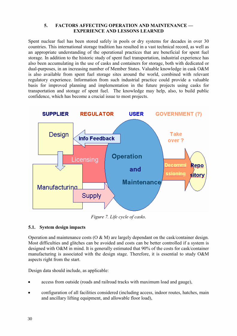
5. FACTORS AFFECTING OPERATION AND MAINTENANCE — EXPERIENCE AND LESSONS LEARNED
Spent nuclear fuel has been stored safely in pools or dry systems for decades in over 30 countries. This international storage tradition has resulted in a vast technical record, as well as an appropriate understanding of the operational practices that are beneficial for spent fuel storage. In addition to the historic study of spent fuel transportation, industrial experience has also been accumulating in the use of casks and containers for storage, both with dedicated or dual-purposes, in an increasing number of Member States. Valuable knowledge in cask O&M is also available from spent fuel storage sites around the world, combined with relevant regulatory experience. Information from such industrial practice could provide a valuable basis for improved planning and implementation in the future projects using casks for transportation and storage of spent fuel. The knowledge may help, also, to build public confidence, which has become a crucial issue to most projects.
Figure 7. Life cycle of casks.
5.1. System design impacts
Operation and maintenance costs (O & M) are largely dependant on the cask/container design. Most difficulties and glitches can be avoided and costs can be better controlled if a system is designed with O&M in mind. It is generally estimated that 90% of the costs for cask/container manufacturing is associated with the design stage. Therefore, it is essential to study O&M aspects right from the start. Design data should include, as applicable:
• access from outside (roads and railroad tracks with maximum load and gauge),
• configuration of all facilities considered (including access, indoor routes, hatches, main and ancillary lifting equipment, and allowable floor load),
30

• suitability of cask materials, consumables, and processes for the plant and the environment,
• compatibility of components, and durability of the assembly over the lifetime of the cask,
• protection against chemical and electrochemical corrosion in operation, transport, and storage (such as grease, paint, and coating materials), and
• reserve sources of power generation and fire protection systems as required.
5.1.1. Operability considerations Great care should be devoted to assuring a smooth and safe operation. This includes but is not limited to: • fail-safe systems including distinctive shapes so that parts cannot be misused,
switched, misassembled, or lost,
• limiting movability in active parts of external power requirements,
• avoidance of small items that are difficult to handle with gloves, and can be dropped in the cask or in a pond and become inaccessible,
• easy removal of all subassemblies and parts,
• reasonable torques and weights,
• compatibility of rigging and lifting equipment (this equipment should be interchangeable between components when possible),
• standard tooling, except if inadvertent tampering must be prevented,
• compatible materials against seizure,
• simple kinematics,
• sufficient "elbow room" and storage space in the considered premises,
• finding the balance between limitations in the number of components and the risk of damage to unmovable (e.g. welded) parts (i.e. Helicoils should be installed in all threads),
• preparation of operating and emergency procedures, including provisions for tools, personnel, and documents,
• test operation and system qualification before loading actual radioactive materials, and
• limitation of dose intakes (see Section 6 for more details), including: shielding, short operation duration, remote operation in case of high dose rates or contamination, prevention of contamination build-up (no contamination traps, smooth and
31

decontaminable surfaces such as electropolishing, paint, peel able coating), and rinsing possibilities.
5.1.2. Maintainability considerations A maintainability study is essential at the design stage. It should be based on a FMECA study, and the return of experience gained from previous cask models. Design output documents should include a maintenance programme, instruction manual, a list of spare parts that should be kept available, and list of parts that should travel with the cask. Any part or function that is determined as sensitive should be subject to maintenance. It should, therefore, be made controllable and interchangeable. Inspection methods should be listed. The facilities where the cask can be maintained and decontaminated should be determined at: existence, possible modifications, specific tools and/or lifting gear. Spare parts should be selected from standard and, preferably, already owned sizes. Future availability should be considered; single-source and patented parts should be avoided. Long procurement time and shelf life should be taken into account for proper stock management. Shelf life should be specified by the vendor and should be compatible with the intended use of the cask (for instance, no elastomer gaskets for long term storage casks). Both operation and maintenance will be impacted by the cask size. In order to pack more fuel in a cask, designers will augment size and weight. For O&M, this will limit the margins for lifting equipment and ground load, and reduce the clearance to walls and working areas. It will also require larger transfer and transport means. On the maintenance side, larger sizes make sense as it means fewer casks, and because maintenance is dictated more by the number of parts than by the accessible area and/or weight.
5.1.3. Ancillary systems and infrastructure
Ancillary systems may have to be modified in order to accommodate new casks. Particular issues such as drying equipment, re-flooding equipment, ventilation, and radiological monitoring should be addressed, as modifications may be necessary. The corresponding instruction manuals, procedures and maintenance specifications should be prepared or revised accordingly.
The weight of the cask and the free-drop height in shafts may require specific energy-absorbing structures or devices. The lifting capacity or plant cranes may have to be upgraded, as well as any overflow area such as parts of the spent fuel pool bottom.
5.1.4. Facility (modification)
Any installation designed to accommodate casks should be subject to the applicable local site regulations, depending of the total activity envisioned.
Access to such installation should be studied such as road or railroad load and width, turning radiuses, slope, etc. Tilting areas should be considered, as well as adequate headroom including lifting beams, hooks, and cask height.
32

Climatic conditions should be considered, specifically to check whether outdoor storage is acceptable over the foreseen storage period. Climatic and other environmental conditions (wind, temperature, visibility, daylight, etc.) should be specified for operation and on-site transfer.
When a facility is modified, all new equipment should be tested, instructions revised, and personnel trained accordingly.
5.2. Operational experiences
Figure 8 Cask operations (TN-13/2).
5.2.1. Schedule
Schedule should provide for contingency in case of deviation from time-critical steps during a loading, such as a time-to-boil or requirement for supplemental cooling during dry transfer. 5.2.2. Technical
5.2.2.1. Contamination
Contamination has proved to be a problem, and a large experience has been accumulated. There were a couple of technical documents published by IAEA addressing the issues of contamination and decontamination of casks [28][29].
Counter-measures against contamination recommended for storage include: the use of plastic and metal skirts, duplication of contamination measurements, and use of easily cleaned or removed materials, special paints, and spraying with clean water before placing in the pool.
33

5.2.2.2. Sealing experiences
Adequate protection from environmental exposure is essential. For bolted casks, seal surfaces are a critical part for leak-tightness. Special precautions should be taken to protect those surfaces, such as plastic rings covering the seal surfaces. Any threads should also be protected or plugged.
5.2.2.3. Interaction between components and with the environment
Corrosion-sensitive materials should be protected against external influences, including against neighbouring components and plant equipment and fluids. Protective covers should be used whenever possible. Screens over inlet and outlet vents can be used. 5.2.3. Human factors
5.2.3.1. User groups
User groups are always beneficial as it is in the interest of safety and economics to share feedback experience. Utilities and cask vendors might want to set up such groups to exchange operational and maintenance experiences. 5.2.3.2. Training and skills
Staff training is essential and should include full scale, all-inclusive "cold" (i.e. without radioactive materials) tests. Procedures should be validated, and possibly revised and retested, as a result of the tests.
Such training should be regularly repeated whenever equipment or procedures are modified.
Operation experience will improve both time and resource needs. First loading demands will be higher than those of future loadings. Skill level will improve with on-the-job experience.
5.2.3.3. Feedback reporting
Periodic review should be performed on operational events, incidents, defects found during maintenance, and rate of replacements of parts. Reports should be raised and forwarded to clients as applicable and/or requested, as well as to competent authorities, and cask design engineers for new designs and retrofitting.
Feedback studies may be used as support for modifying maintenance frequencies. Information that is made available by the different competent companies/organizations should be analysed on a systematic basis.
5.3. Exposure control
5.3.1. Radiation
• Radiation levels in storage areas should be monitored, recorded and any changes should be analysed.
• Additional temporary shielding can be designed and utilized, such as polyethylene sheets against streaming from designated spots and against general radiation from the cask.
34

• Dry runs to improve actual time to perform task are necessary, as well as tool staging, equipment location and design to facilitate the users.
5.3.2. Hazardous materials and situations All precautions in occupational safety remain applicable: protection against fall, heat, pressure, and oxygen deprivation, as well as harmful chemicals such as asbestos and lead. When incidents or accidents may give rise to such exposure, the instruction manuals should warn against it and provide the necessary safety precautions. When lifting gear travels with the cask, the receiving facility should check whether any inspection is requested, including regulatory tests. It is also necessary to prevent spurious movement of the conveyances when tilting the cask.
5.4. Specific examples
5.4.1. Technical issues
5.4.1.1. Hydrogen control
Hydrogen may be generated as a result of radiolysis or chemical reactions. Recombiners and/or getters should be used to preclude any risk of ignition or blast. 5.4.1.2. Welding
• Welding material and equipment should be checked before welding operations begin.
• Use of automated welding machines has become an industry practice for seal welding of the canisters.
• Adequacy of critical welds should be verified as specified in the design specifications and drawings. Specific UT (Ultrasonic Tests) or NDE (Non-Destructive Examination) requirements may be called for.
Active developments have been pursued in the welding of the canister opening with the cover, together with subsequent operations. Highly automated welding systems for spent fuel container/canister welding are available on the market. Some technical problems associated with welding of canister closure in storage casks were reported in the USA by USNRC inspection and appropriate corrective measures were taken [30]. 5.4.1.3. Coating selection
Coatings (both internal and external) should be specified and selected for the following characteristics: durability, decontaminability, emission and absorption, ability to undergo touch-up and repairs on the loaded (warm) cask.
5.4.2. Handling damage
Protection should be mounted on the closing and/or leak tightness surfaces of the cask during handling and maintenance operations (avoiding scratches on sensitive surfaces).
35
Procedures should request the verification of any handling tools before use. Procedures should also avoid the handling of small tools or devices in the vicinity of the open cask (limitation of tool drops in the cask). The personnel should be trained for using the handling devices. The cask surfaces should protect during cask handling as: protective plastic plates mounted on area where moving devices are handled, hard metallic layer on the bottom, and a protective rubber liner under the cask during rail way transport. 5.4.2.1. Trunnion sealants
Bolted trunnions have a gap around their base, where water may flow. These gaps can be sealed with silicone. The heads of the screws are also covered by silicone. In order to protect against contamination of the silicone gaskets, and provide additional protection against seepage of contaminated water, adhesive tape and metallic covers with o-ring seals are frequently used (over the silicone) before immersion. Drying and leak testing procedures may be beneficial. 5.4.2.2. Skirt usage for contamination control
Some designs are prone to trapping contamination, especially when submerged. Precautions such as installing a skirt around the body will significantly reduce contamination. Circulating dematerialized water under the skirt will cool the loaded cask and avoid any pool water ingress. Skirts are usually made of stainless steel or plastic. 5.4.2.3. Storage conditions of casks not in use
Any cask should be protected from weather conditions whenever possible. It is best to keep it indoors when it is not in use. Tarpaulins are not advised as they usually cause condensation that may induce corrosion. Special provisions such as inert gas filling may be specified in operating instructions. Adequate precautions should be taken to remove any device or gas before using the cask again. 5.4.2.4. Connecting tools
It is recommended to have universal connecting tools that fit all types of casks. Utilities should specify their requirements to the vendors.
5.4.3. Pre-installation check
Before they are installed or closed, all components including seal areas and spare parts should be inspected, at least visually, in order to make sure that they are in perfect condition and fit for installation. For gaskets, damage and scratches, remaining shelf life should be particularly inspected. For spare parts, inspection should take place in a no-radiation zone and adequate numbers of spare parts should be verified.
Consideration should be given to leak testing regimes and standard procedures should be developed for leak testing.
36

6. FUTURE ISSUES
The recent trend in spent fuel storage shows a growing preference for dry storage systems for storage of spent fuel, which are required as a platform for any options to be chosen for a fuel cycle backend. The current outlook is that this trend will likely to continue creating the need to prepare for extended storage of increasing amounts of spent fuel around the world.
As for prolonged storage, there is confidence in coping with the long term storage requirements without major technical issues. Such confidence is built on the extensive industrial experience gained in spent fuel storage, and especially on the recent development of dry storage systems. These systems are beneficial for long term storage, since the spent fuel is kept in an inert sealed atmosphere. Storage in casks under inert conditions is now the preferred option, given advantages such as passive cooling features and a modular mode of capacity increase. In terms of economics, dry storage is particularly propitious for long term storage in that operational costs are minimized by the passive cooling features. 6.1. Cask/container development and design
A variety of storage systems have been developed to meet the specific requirements of different reactor fuels. A large number of designs based on these generic technologies are now available for the spent fuel containers (horizontal, vertical etc) and storage facilities. Multi-purpose technologies (i.e. a single technology for storage, transportation and disposal) have also been studied. A dozen models of dry storage casks have been commercialized over the past couple of decades for additional storage, especially for AFR type facilities. The casks can be purchased from the competitive market for expedited installation, on the assumption that the necessary licenses are acquired and there is no barrier from the local community.
The more than 50-years of international experience with spent fuel storage accompanied by ongoing research have resulted in an extensive scientific base and an appropriate technical understanding of the behaviour of spent fuel and storage systems. For many countries, including those Member States pursuing reprocessing, discussions have continued for over 100 years.
6.1.1. Trend to larger cask
O&M will be impacted by cask size. Cask designers can augment size and weight in order to pack more fuel in a cask, mainly driven so for cost-effectiveness. Both operation and maintenance will be impacted by the cask size. In order to pack more fuel in a cask, designers will augment size and weight. For O&M, this will limit the margins for lifting equipment and ground load, and reduce the clearance to walls and working areas. It will also require larger transfer and transport means. On the maintenance side, larger sizes make sense as it means fewer casks, and because maintenance is dictated more by the number of parts than by the accessible area and/or weight [31]. 6.1.2. Trend to high burnup (HBU) and mixed oxide (MOX) fuel use
The fuel burnup in the nuclear industry has continued to show an upward trend, mainly driven by economic considerations in the competitive market. Fuel failures are a concern both from reactor operation and fuel storage point of view. However, fuel failure rates are diminishing. The main failure causes at present day are debris and grid to rod fretting. These failure mechanisms are not strongly dependent on burnup, and therefore, the strive for higher burnup has not lead to an increased number of fuel failures.
37

The current methods employed to handle the more hostile characteristics of HBU fuel and MOX fuel are either to keep them for a longer period to decay in the cooling pool, or in some inevitable cases, requiring to be placed in restrictive storage conditions such as casks, combinatorial loading with lower burnup or longer cooled spent fuel, or even partial filling of the available spaces at the cost of underrating the cask usage. Emerging technologies could evolve over this period to enable buffer storage in dry systems, e.g. casks with forced cooling.
6.1.2.1. HBU
Although this trend to higher burnup is foreseen to be constrained at a certain level by regulatory notches or other balancing factors, and despite the fact that overall rate of accumulation of spent fuel assemblies should decline because of extended reactor residence time of HBU fuel, the preparation for storing spent fuel of higher burnup has become an active issue in a growing number of countries because of the higher heat and radioactivity content.
6.1.2.2. MOX
In a similar token, the increasing amount of MOX fuel used in LWRs, as observed in Europe, will result in growing inventory of spent MOX fuel with still higher content of heat and radioactivity than high burnup UOX fuel.
6.1.2.3. Burnup credit
Application of burnup credit can make a significant improvement by demonstrating real margin of safety in criticality calculations. Spent fuel management facilities were typically underrated for criticality safety, because it is generally regulated by licensing conservatism based on fresh fuel. Enhancements in burnup credit applications are making progress in some countries [32].
6.2. Systems design
6.2.1. Multi-purpose systems
The increasing use of casks for dual-purposes on one hand, and the ramifications of diverse storage casks with canisters on the other, also raises an issue of longer term consideration for the optimisation of the overall operation by use of a uniform container design which would be compatible with diverse package designs. A well known example is the USDOE initiative to develop a MPC (Multi-Purpose Canister) which was supposed to provide standardization as required for compatibility of interface between different stages of the spent fuel management. Several vendors have developed MPC designs for possible applications in the market [33]. 6.2.1.1. Safety and security of spent fuel
Nuclear safety and security have become a topic of acute debate on nuclear facilities, including spent fuel storage, especially since the events of September 11, 2001. Apart from the nuclear power plant itself, effects of a terror attack on the AFR storage facilities have been in evaluation. While concerns were expressed on the wet type storage facilities, cask type facilities are evaluated to be largely resistant to such damages as a plane crash [34].
More recently these issues are compounded with security and physical protection questions for which underground options are attracting interest. The future evolution of requirements
38

and technologies might bring important impacts on cask O&M for spent fuel storage facilities. 6.2.1.2. Retrievability of spent fuel
One of the key issues associated with long term storage of spent fuel is to ensure by design, operation and institutional management the retrievability of spent fuel at the end of the storage period.
Consideration needs to be given to receipt and fuel retrieval if casks are sent for repackaging at a repository. Regulators have expressed interest into the issue of fuel integrity following extended storage periods, in particular the integrity of the cladding or the structural integrity of the fuel assembly itself, particularly if the basket conditions may cause fuel to stick during its retrieval and removal from the cask [35].
A variety of storage systems have been developed to meet specific requirements of different reactor fuels and a large number of designs based on these generic technologies are now available for the spent fuel containers (horizontal, vertical, etc.) and storage facilities. Multi-purpose technologies (i.e. a single technology for storage, transportation and disposal) have also been studied. Recent concern on security measures for protection of spent fuel has prompted a consideration on the possibility of placing a storage facility underground. The future evolution of requirements and technologies will bring important impacts on cask O&M for spent fuel storage.
6.2.1.3. Standardization of systems
The development of casks for dual and multiple purposes also raises an issue of longer term consideration for the optimization of the overall operation by possible standardization of inner containers for accommodating various characteristics of spent fuel, as required for compatibility of interface between different stages of the spent fuel management. When considering multi-purpose container technologies, it is important to recognize two distinct categories: This could be dual-purpose (storage and transportation) or multi-purpose (storage, transport and disposal) casks/containers. For either type, the system involves the design for more than one function. The multi-purpose canister (MPC) system was proposed in the USA with a view to unify the design specifications in order to provide compatibility with storage, transportation, and disposal. The MPC is supposed to containerize spent fuel assemblies at reactor sites and be used as such throughout storage, without the need to be opened, to the disposal. Although DOE provided the specifications for the MPC to both vendors and utilities, the lack of finalized design for disposal package in the Federal Waste Management System rendered MPC undefined for further pursuance of the approach. Several utilities and vendors have pursued the MPC design for dual-purpose cask systems which could bring substantial savings, compared to repacking spent fuel, should those canisters prove to meet the disposal package requirements. European Union has recently initiated a research programme (SAFE CASK) to look at the technical feasibility of enhancing efficiency as well as safety of casks for storage and/or disposal of spent fuel [36].
39

6.2.2. Dose reduction measures
Reduction of doses receivable by workers is one of the key measures taken into consideration for cask operation (and maintenances). There are various techniques and equipment are available to reduce the personal and the collective dose, [37].
6.2.2.1. Spent fuel operations
After loading the cask with fuel, several preparations can be done as a remote control technique, e.g. vacuum drying, leak testing (partly), bolting/unbolting the lids, etc. Following this matter, it is possible to reduce the number of people in the area of the loaded cask.
It is also very important to plan the work to be done at the loaded cask to reduce time. A quality plan or a step-by-step sequence is necessary. This plan should be reviewed from time to time, at minimum after the first cask loadings or unloading, to optimize the procedure and the organization of the work. After a campaign (several loadings or unloading) a lessons learned report should be prepared to capture the experience.
Several industrial experiences in remote-controlled unloading of casks are made, for instance, at the COGEMA Unloading Facility T0 in La Hague (F) and at the BNFL THORP Receipt and Storage building B 560 in Sellafield (UK).
When storing the fuel in metal canisters (within concrete modules,) automatic welding machines are used to minimize the personal dose rate.
Automatic systems, for example ultra sonic inspection or remote visual inspection by using cameras, are also available.
Although the position of the fuel elements into the cask could be non-specific, it is a good practice to load the hottest fuel in the centre of the basket and the coolest at the outside to reduce the dose rate. That aspect has to be included in the loading plan.
Traditional techniques also used to reduce the dose rate are:
• to reduce time in the area of the loaded cask,
• to optimize the distance, and
• the use of temporary shielding equipment etc.
6.2.2.2. Storage areas and buildings
To reduce the dose rate and the effect on population outside of the storage site, different techniques are used. It is very helpful and efficient to have a plan to position the casks in a pattern that takes in account the ALARA concept.
There are different storage concepts. Earthen berms may be uses as shielding, as well as an increased distance to the site boundary.
40

6.2.2.3. Casks/containers
This is covered in Section 5.1 System Design.
6.3. Shipping to further destinations
There may be a number of reasons to transfer casks from the storage site. Some of these reasons are discussed in this section.
6.3.1. Cask/container transfer between facilities
6.3.1.1. AR
A cask may need to be moved from one storage location to another storage location such as transfer to another storage facility or transportation to a central storage location. The reasons for this may include the consolidation of storage facilities in a particular region or country dictated by political reasons, or economic reasons such as allowing the complete decommissioning of the facilities at a reactor site.
6.3.1.2. AFR
A cask may need to move from the storage site to the repository. Consideration needs to be given to the type of storage technology to be used and the design of the disposal facility. Within the United States, some storage technologies were based on sealed canisters contained within concrete storage casks with the intention that the canister can serve as a containment boundary in the repository without the requirement to unload the fuel. However, the spent fuel repository design or the geological conditions within which the fuel will be stored may mean the repacking of containers, if the requirements for the repository are not fully met by the container design. Alternative repository designs intend to repack the fuel in multi-purpose designed containers or casks prior to disposal. This principle is intended for use in Germany where casks will be received at the Pilot Conditioning Plant, which will remove the spent fuel from the storage cask and consolidate the fuel prior to repacking into disposal casks for disposal in an underground repository.
6.3.1.3. Reprocessing
It is difficult for cask designers and operators to guarantee events following storage, as this depends on a number of factors that may not be technically based (see Section 6.4 Non-Technical Issues). However, once a cask has been in storage for a period of time (e.g. 20, 30 or 40 years) there are issues to be considered as decisions are made on how to transport the materials away from the storage site.
These include:
• Record keeping requirements (See Section 6.5.1. — Licensing Issues),
• Maintenance requirements both during long term storage and just prior to transportation, and
• Preparation activities for transportation.
41

6.3.2. Maintenance requirements before transportation
The maintenance requirements vary and depend on present and future regulatory regimes, designer recommendations or the storage cask owner's policy. In addition, experience gained during the storage period may dictate and change policies. For example, deterioration may be less than predicted for certain components and requirements may be relaxed, or alternatively enhanced, if experience suggested more oversight is required. Maintenance prior to transport may include activities discussed in this section.
6.3.2.1. Simple visual checks of the casks external condition or accessible components
The criteria of such inspection would be to confirm that the surface condition does not exhibit signs of deterioration and to confirm that the cask lid is fit for the transport. This approach is currently advocated by Germany and has the advantages of requiring fewer facilities associated with the storage site. However, provisions need to be made in case the visual inspection identifies concerns that need to be addressed before the authorities allow a release for transport.
6.3.2.2. Actual testing of component parts such as the inspection and overload testing of lifting devices prior to their use for lifting, or leak tightness checks of lid seals and cask orifices
Although these tests are confirmatory checks to ensure that the cask is suitable for transport, recovery plans and facilities need to be considered in case a test identifies the need to repair or replace components. For example, some cask designs utilize secondary or even tertiary (third) lids, which will allow transport even if there is a failure of the primary lid seal. In some instances, the additional lid is welded in place to ensure leak tightness for transport.
6.3.2.3. Replacement or refurbishment such as the possible change of seals or gaskets, and replacement of screws or the repair of paint
If such a maintenance policy is considered, then the storage site needs to include appropriate facilities. If replacement is limited to lifting points or localized repair of paint, then these may be temporary facilities erected at the time of maintenance prior to transport. However, if the intention is to replace seals or gaskets and this is a recommendation of the designers, then consideration to hot cell facilities may need to be taken into account at the initial design and construction of the interim storage facility. An example of such a hot cell is at Zwilag in Switzerland, which provides full maintenance operability to repair and replace gaskets.
6.3.3. Preparation for transport
Additional preparation steps may be necessary prior to transport. The technology type also dictates the necessary steps and ancillary equipment required.
6.3.3.1. Metal casks
Considering metallic dual-purpose casks, the following preparation activities need to be considered:
• Removal of the cask from its vertical storage location, tilting to the horizontal on its transport frame
42

• Fitting of transport impact limiters / shock absorbers
• Fitting, or even welding, of additional lids and the leak tightness testing
• Regulatory tests, such as radiological, contamination and thermal checks
Consideration needs to be given to receipt and fuel retrieval if casks are sent for repackaging at a repository. Regulators have expressed an interest in the issue of fuel integrity following extended interim storage periods, particularly with respect to the integrity of the cladding or the structural integrity of the fuel assembly itself, especially if the basket conditions may cause fuel to stick during its retrieval and removal from the cask.
6.3.3.2. Concrete casks
Considering concrete cask and canister-based storage technologies, the following preparation steps include:
• Withdrawal, transfer and loading of the canister from the concrete cask into the transportation cask. This may be achieved by returning the canister back to the spent fuel building and using the Reactor’s crane and pool for the operation. However, it is likely the reactor pool has been decommissioned. Therefore, transfer equipment, such as a stand-alone transfer station including a transfer cask, is available at the storage site. Temporary cranes may need to be brought to the storage site to perform the lifting operations.
• Transportation cask preparation may include tilting horizontally on its transport frame following canister loading and lid fitting, pre-dispatch testing of seals, and regulatory checks (radiation and thermal checks). If the reactor facility has been decommissioned, then all the equipment and facilities required to perform these activities need to be present.
6.4. Decommissioning
6.4.1. Casks/containers
After their useful life, casks will have to be disposed of or recycled. This decommissioning may come after changing the purpose of the cask, such as conversion from transport to storage or vice-versa, or such as storage of other waste equipment.
Environmental considerations will be important factors in this decision-making. The following issues should be considered.
6.4.1.1. Design considerations
Initial design should include a study of future disposal possibilities, and evaluate the use of environmentally friendly materials.
6.4.1.2. Final destinations
Depending on the future physical and radiological state of the cask, of the then-existing repositories, and of the available technologies, casks will be stored as-is, or partially or totally deconstructed. Ownership may change at that stage.
43

In some cases, when the radionuclide content will be below the regulatory limit for radioactive waste disposal, disposal in non-nuclear repositories could be allowed. In this case, destruction is advisable as it will permit recycling a large part of materials, such as steel, lead, cast iron, aluminium, depleted uranium. The exception would be the presence of prohibited or controlled materials, if its destruction leads to unnecessary exposure to workers or the public.
Storage as-is is recommendable if there are clear disadvantages in taking the cask apart: dispersal of radioactive material or other contaminants, creation of further waste such as tools and consumable, and exposure to workers. Partial destruction may allow reclaiming valuable materials only. There is experience with lead retrieval in France. However, it appears that in most cases, only environmental considerations can outweigh the high cost of using nuclear facilities and workers for little gain.
Waste, or the entire cask/container, has to be classified. The type and level of contamination or will direct the cask to a respective type of repository. Prior decontamination of external and/or internal surfaces may lower the cost of transport and disposal, but this should be decided on a case-by-case basis.
6.4.1.3. Cost considerations
Adequate decommissioning funds should be set-aside over the operational lifetime of the cask to cover the associated costs. Their level is not easily determined since regulations, available facilities, and repositories will change in time. As a rule of thumb, 15% of the purchase price would be a safe level when high contamination and some activation are expected. 6.4.2. Facilities
Decommissioning facilities, and more generally reducing infrastructure such as cranes and roads, should be considered for its impact on cask use. For transport casks, the continued availability of decontamination and maintenance facilities is essential. These facilities may be on-site or not, as long as the approval conditions for maintenance are met. For storage casks, the continued existence of a hot cell may be required, if operations such as repairs or fuel retrieval are anticipated for any reason. Dual-purpose casks may be subject to all these limitations, in the course of time.
The site license for storage may be conditioned by continued availability of ancillary facilities, or adequate alternative solutions such as additional cask closure systems.
6.5. Other issues
6.5.1. Licensing issues
There is a scientific and technical consensus that the current technologies of spent fuel storage adequately protect humans and the environment. Because of enhanced confidence in storage technologies, it is conceivable that operators of new facilities may request initial operating licenses for periods beyond those traditionally approved by regulatory authorities, in accordance with license extensions for nuclear power stations now actively pursued in an increasing number of Member States. In this regard, proactive measures are undertaken by the nuclear industry and regulatory agencies in various countries.
44

The licensing process of a storage facility may involve the facility license, but also the cask(s) license(s). The last would be for the storage only, or it implies two licenses, for storage and transportation (in the case of dual-purpose casks).
The regulations during storage periods may evolve to be different from those used during the initial licensing process. The changes may affect the transport certificate which is usually given for a shorter period of time than the storage license. There is a possibility that a cask cannot comply with future regulations and cannot be licensed and transported anymore.
In some countries, like Belgium, Germany, or Spain, the storage license is linked to the transport cask. A transport licence remains valid for a limited period of time. Within European Member States, this license period is between 3 to 5 years. For a dual-purpose cask, it may be necessary in some countries that the transport license remains valid throughout the storage period, even though the cask is not transported. Some national laws assume that storage casks/containers will have to be transported at any instance; therefore, a transport license has to be held on a continuous basis, even though the cask is in storage with no transport planned. Germany has licensed its casks for 40 years, but the duration of the cask license is, in most of the cases, less than the design life of the cask. This implies a renewal process. In the United States, the initial duration of the cask and site storage license is 20 years. During all the life of the cask, there has to be record keeping requirements covered by the QA programme (see Sections 3.1.5 and 3.2.5). These records have to include information about cask manufacturing, loading (including also relevant information about the fuel stored), periodic testing results, maintenance and monitoring activities, etc. This information has to be available. The use of advance cladding materials and the increase of the burn up limit implies a possibly more degraded fuel. These new fuels do not have any historic experimental data on their behaviour under storage conditions. A research programme has been launched in Spain in to measure creep behaviour of high burnup zircaloy-clad fuel under dry storage conditions. 6.5.2. Global acceptance
Transportation and storage of spent fuel are activities of interest for many stakeholders; this interest is increasing with each new transport or storage project. Stakeholders include (but are not limited to) the public, the policymakers at all levels, the media, activist groups, the industry and the regulators. They also include third-party states, multinational and intergovernmental bodies. The NIMBY concept (not in my backyard) is complemented by the "not through my backyard" in the nuclear field.
For transport and storage activities to take place, the industry, with or without assistance from national authorities, must take action so that: their activities are better known, are kept as transparent as possible, and are finally accepted as safe and not detrimental to others.
There is a large experience in the field of public acceptance, global acceptance (i.e. including states, politicians, media, etc.), and public outreach. The aim of these actions is to build confidence and at least obtain a neutral position based on facts, not impressions.
An example of this are the actions by so-called "shipping states" to inform the so-called "coastal states" on the safety of transport operations, because of the wealth of precautions taken in accordance with IAEA regulations.
45

Another example is the public hearing systems where all concerns may be voiced and can be answered [38].
6.5.3. Country policy changes
Storage and disposal decisions are very vulnerable to political change in a number of countries. Opposition to, or delay of the repository construction (or transport to repository), may lead to an expanded period of storage. This may induce delays in closing and restoring certain sites. Some opposition may be due to disputes between local and national authorities.
In many Member States, deregulation of the energy market has resulted in the privatization of former public utilities, as well as the shrinking of the market as the internationalization of businesses leads to the merger of a number of companies in the nuclear sector.
6.5.4. Business aspects and economics
One of the driving forces of this trend towards dry storage options (especially those of casks) is the inherent technical flexibility linked to economics. In comparison to the pool facilities need for initial construction at full capacity, the modular type dry facilities can be added as needed with the advantage of minimizing capital outlay.
• The adequacy of the frequency of maintenance should be regularly reviewed. Specifically, older inspection methods should be evaluated against better, newer methods.
• Stability of regulation is favourable, and for storage casks could lead to longer validity of licences and approval granted by the authorities.
• Choosing experienced contractors may be beneficial as opposed to buying and operating equipment that would be underused and aging, and operation by plant personnel who would not easily maintain proficiency and qualification. Examples are welding, lifting, and non-destructive testing.
• Ancillary equipment should be kept to a minimum quantity and complexity.
7. CONCLUSIONS
7.1. Status and trends in cask/container storage
The current trend toward extended storage is likely to continue in the foreseeable future. In fact, storage is an essential platform for any option to be chosen later as an endpoint for spent fuel management.
In view of such a circumstance, adequate storage for the future spent fuel inventory arising (either from the continued operation of nuclear power plants or from the removal of spent fuel in preparation for plant decommissioning) is the most imminent service required for the spent fuel management worldwide.
46

While the bulk of the global inventory of spent fuel is still stored in AR pools, dry storage has become a prominent alternative especially for newly built away from reactor (AFR) facilities. Such facilities already house more than 17,000 tHM in dry storage facilities worldwide. Storage in casks under inert conditions has become the preferred option, given the advantages of passive cooling features and modular mode of capacity increase.
7.1.1. Dry storage
A review of spent fuel storage facilities implemented during the last 10-20 years shows that storage in a dry environment is becoming more common. There are several generic types of these technologies available from vendors on the international market. Prominent among them are: metal casks in which spent fuel assemblies or consolidated spent fuel canisters can be accommodated in suitable baskets, and concrete casks in which spent fuel enclosed in canisters can be accommodated as a separable package.
In terms of economics, dry storage is particularly propitious for long term storage in that operational costs are minimized by the passive cooling features. The trend toward dry storage, especially in the cask type, is likely to continue with an implication that the supply will closely follow the increasing demand for storage by incremental additions of casks. This will, in effect, minimize the cost penalty of the idle capacities typical of pool facilities.
7.1.2. Technical options
There are also a large number of facility designs based on these generic technologies that are now available. These technologies differ largely in terms of materials of construction, size, modularity, spent fuel configuration, layout of the storage containers (horizontal, vertical, etc.) and methods for fuel handling. Multi-purpose technologies (i.e. a single canister design for storage, transportation and disposal) have also been studied in some countries. Despite the benefits expected from standardization by the multi-purpose canister (MPC) concept, the uncertainty of the final form of the disposal package has deferred any definite concept for the MPC design. Further differences lie in the spent fuel’s placement above or below the earth’s surface. An increasing number of storage facilities are coming into operation for each of these types.
Although there is no clear favorite global technology, the dry storage of spent fuel in casks is being particularly recognized as a flexible option with the advantages of: transportability in case of future need, incremental investment as needed, the possibility to lease casks from vendors, and the passive feature of dry storage.
7.2. Cask/container operation and maintenance
During the past several decades of development, the cask industry has matured, providing products and services with reliable safety and competitive supply. It has now become a matter of selecting a system offered in the market for specific spent fuel storage requirements. The general requirements of transportation and storage should be identified at the beginning of the facility selection process including the accessibility for rail/road/water between the fuel cycle components. If there is any preference related to the fuel handling and preparation before storing the fuel in the AFR facility (such as spent fuel drying, inert gas filling and sealing of containers before placing in dry storage), it should be defined. Such preferences may also relate to the location where such activities are carried out, i.e., NPP sites versus AFR storage at a centralized facility site.
47

7.2.1. AR operations
An important functional operation performed at reactor water pool storage facilities is the loading of spent fuel into transportation casks (or unloading of spent fuel in some special cases) for shipping elsewhere. The packages used for transport of spent fuel are heavy, shielded casks which may or may not be filled with water. Spent fuel is loaded into the cask in the pool and the lid is placed before the loaded cask is to be taken out of the pool. A sequence of operations is followed (such as draining and drying, sealing of the lid and bolting the cover, decontamination, etc., as required). Careful preparation of the shipping cask for transportation has become an important issue especially since the recent finding of cask surface contamination in Europe. As more spent fuels are stored long term at dry storage facilities, sealing the lid on top of the canister is usually done by remote welding and /or covered with a metal gasket tightened by bolts. Licensed transportation containers are usually readily available from a variety of suppliers or they can be readily developed to meet specific requirements, if necessary. However, one must pay attention to docking regulations and systems for handling the fuel from transportation containers. Depending on the type of fuel involved, containers may have to be customized in some cases. Leasing of these containers and subcontracting of transportation services are also available options for consideration
7.2.2. Cask/container operation and maintenance
One of the key requirements for the spent fuel management facilities is the strict containment of radionuclides that can be released i.e. as fission gases from spent fuel rods. Casks/containers are the most common method used as barriers for such containment, as it is widely used to manage defect fuel in AR storage. While the closure of a cask/canister can be effectuated by such mechanical method as clamping with packing depending on the requirement, welding is the most popular method used ubiquitously on canisters, while the clamping/bolting method is typically used for cask closure for the inner lid. As a measure to enhance safety, the sealed canister is filled with inert gas (most often helium). All operations involved in the closure of canister have to be performed remotely to minimize dose to workers.
7.3. Future issues
Spent fuel storage projects are subject to the same type of risks and uncertainties to which other nuclear projects are exposed. These include:
7.3.1. External factors
The external factors that will have to be considered may include:
(a) Regulatory actions
(b) Litigation
(c) Political action
(d) Public (activist) opposition
48

7.3.2. Internal factors
The internal factors that will have to be considered are as minimum:
(a) Cost
(b) Schedule
The foregoing external factors impact cost and schedule, and must be mitigated promptly and to the extent reasonably possible. However, the foregoing internal factors are otherwise basically under the control of the owner of the spent fuel storage project. Thus, cost estimates should contain sufficient realistic contingency, schedules should be comfortably achievable with reasonable diligence, the satisfactory reliability of the supplier of the storage technology should be established with its performance subject to contractual assurances, and diligence should be maintained in oversight of QA activities. If these are not accomplished such that timely adjustment in activities is possible, the project can be exposed to unacceptable cost overruns and delays. 7.3.3. International services
The current trend toward the globalization of the market economy, which has already brought important impacts on nuclear industry, might have a stimulating effect on regional/international co-operation for cost-effective approach to mitigate some of those long term issues associated with spent fuel management
Very recently, there has emerged a sign of development for “cradle to grave” service, meaning the provision of commercial services for comprehensive fuel cycle requirements. This is a service concept based on the lease rather than purchase of fuel by the utilities in which fuel will be returned to the supplier after use, thus relieving the utilities from liability of deciding on spent fuel management. This may be partly compared to the commercial reprocessing services in Western and Eastern Europe, which provide de facto regional services, but with a difference of covering an integral life-cycle service for the entire fuel cycle. This concept seems to go well with the recent tendency toward liberalization and globalization of the nuclear energy sector, and in that matter, better match with the regional or international management of spent fuel.
49


APPENDIX I. COMMERCIAL CASKS FOR SPENT FUEL STORAGE
(P=PWR, B=BWR, C=CANDU, W=WWER (440/1000), R=RBMK, H=HTR)
(listed by alphabetical order of supplier/owner names), as of 2005
CASKS/CANISTER TECHNICAL REQUIREMENTS SUPPLIER/
OWNER Product Model
Number of Fuel Element
Maximum Burnup (GWd/tHM)
Maximum Heat Load (KW)
Total Wt.(MT)
AECL Concrete Silo3 360C
342C
486C
540C
9
9
9
9
1.8
1.71
2.4
2.7
BNFL Fuel
Solutions
metal cask and
concrete cask
TS-125
VSC-24
W-150
W-21 (Canister)
W-74 (Canister)
MSB
21P/64B
24P
21P/64B
21P
64B
24P
51.8/45
15~60
15~40
45
22
24
24.8/25.1
22/25.1
17.6/24.8
24
139
144
160
?
ENSA DPT 21P 40 27.3 113/114
CASTOR 1C
CASTOR-V/19
CASTOR-V52
CASTOR-V/21A
CASTOR Va
CASTOR Vb
CASTOR X28
CASTOR V21 (Surry)
CASTOR X33F
CASTOR-440/84
CASTOR RBMK
CASTOR THTR/
CASTOR AVR
16B
19P
52B
24P
21P
24P
28P
32B
33P
84W440
102
ca. 2,100H4
ca.1,900
35
65
65
60
75
75
37.5
60
60
42
29
114
115
14,4
39
40
34
40
34
17.2
32
16.6
21
12.5
Ca.0.2
Ca.0.2
81.1
125.6
123.4
119
126.2
110.4
133
107.9
107.3
116
117
32
30
GNS
CASTOR
family
metal cask
and
CONSTOR
family concrete cask
CONSTOR-440/84
CONSTOR-1000/19
CONSTORRBMK
84W440
19W1000
102R5
41
49
30
20
21
7
120
125
84.4
H-Z metal cask for storage 61B 50 17 118
3 Also called concrete canister, NWMO Background Paper 6-1 (2005) 4 Number of spherical (‘pebble’) fuel element 5 The 10m-long assembly of RBMK fuel halved for size fitting into a basket which was also used for emplacement into the metal cask CASTOR at Ignalina site
51

KSL TN-24 32B/37B 33 28/20 113/100
MHI
MSF family
metal cask
MSF-21P
MSF-57B6
MSF-69B
21B
57B
69B
60
63
40
41
49
19
121
123
119
Holtec
International
metal
reinforced
concrete cask
HI-STORM 100
(storage)
and
HII-STAR 100
(transport)
(HI-STAR 100U)7
MPC-24
MPC-32
MPC-68
UMS
61/63
50
54
36
20/28.2
28.7/NA
18.5/28.2
12.5
NAC
International
metal cask
and
concrete cask
NAC-STC
NAC-C28 S/T
NAC-S/T
NAC-MPC
NAC-UMS
MAGNASTOR
26P (BF)
56P (CF)
26P / 28P
36P / 26B
24P / 56B
37P //87B
45
35
45
36/43
50
60
22.1
20
17.4
12.5 / 17.5
23
35(P)/33(B)
127
161
OAO Izhora TUK-104/M
TUK-108/1
57/114 R
72/144 W1000
5
6.3
95/93
39.6
OPG DSC (CIC8) 384 C 9 4.4 70
REA9 REA-2023 24P/52B 33 24/20
ACL10
(former TN) TN Family
Europe
(metal casks)
Transnuclear
TN-24 DH
TN-24XLH A/B
TN-24SH
TN24E
TN-52L
TN-68
TN-97L
TN-24BH
TN-32
TN-40
TN-68
28P
24P
37P
21P
52B
68B
97B
69B
32P
85B
40
55
55
55
75
53
40
26 (av.)
50
45
45
40
33
33
30
40*
40*
21.2
19
40
32.7
32.7
21.1
112
111
96
125
112.5
115
124.5
126
115.5
113
113.8
6 License applied for in Germany. 7 Maureen Conley, “Holtec to ask NRC to approve underground design for dry storage facility”, Nuclear Fuel, 26 April 2004) 8 Prototype model 9 The REA-2023 design right has been alienated to MHI ( communicationby Mr. Yamamoto, MHI, 3. March 2006) 10 P.Dyck, private communication (28 Feb.2006)
52

NY TN Family USA
NUHOMS
Family
Canister-based
concrete module
NUHOMS-07P
NUHOMS-24P
NUHOMS 32P S
NUHOMS-52B
NUHOMS 61B
NUHOMS-F
NUHOMS-MP
NUHOMS 56V
NUHOMS RBMK
7P/18B
24P
32P
52B
61B
13-24P
21P/61B
56 WWER
95 RBMK
45-62
45-62
35
40
40
42
25
7
24-40.8
24-34.8
19.2
15.8/18.3
9.9/13.5
9.9-15.8
48.6
133/136
Westinghouse MC-10 24P/49B 35 13.5 ?
ABBREVIATIONS FOR SUPPLIER/OWNERS: ACL= Areva Cogema Logistics (former Cogema Logistics, Transnucléaire) AECL=Atomic Energy of Canada Limited BNG=British Nuclear Group GA=General Atomics GE=General Electric GNS=Gesellschaft fuer Nukleaire Services KSL=Kobe Steel Ltd. MHI= Mitsubishi Heavy Industries, Ltd. NAC= Nuclear Assurances Corp. NFT=Nuclear Fuel Transport Co.Ltd. OCL = OCL Corporation OPG=Ontario Power Generation REA=Ridihalgh, Egggers and Associates
53


APPENDIX II. COMMERCIAL CASKS FOR SPENT FUEL TRANSPORT P=PWR, B=BWR, W=WWER(440/1000), M=MOX, H=HTGR, R=RBMK, C=CANDU, M=Magnox, A=AGR
CASKS TECHNICAL REQUIREMENTS
FUEL TYPE
OWNER MODEL Capacity (Fuel Assemblies)
Thermal Load (Kw)
Total Wt. (Mt)
REMARK (References.)
BNG NTL-3M
NTL-3MA
NTL-9
NTL-11
NTL-14
NTL-15
EXCELLOX-6
7P
10B
7B
7P
5P
10B
6P
30
10
25
20
45
9
20
54
53
36
78
85
25
95
TRS-24011
UK Report
(G.Jones)
GA GA-4
GA-9
4P
9B
2.47
2.12
27.5
27
GE IF-3000 7P/16B 68-70 60.7
JAI-58212
GNS CASTOR-S1 6P/17B 30 79-82 P.Dyck
H-Z NH-25 1P/2B 7 29
Lehrer LK-80
LK-100
12P
12P/24P
100
30
100
72
MHI MSF-1 1P 6.7 45
Yamamoto
TRS-240
NAC NAC-LWT
NLI-1/2
NLI-10/24
1P/2B
1P/2B
10P/24B
11.5
10.6
70
25.6
23.1
97
Yamamoto
NFT NFT-10P
NFT-14P
NFT-12B
NFT-22B
NFT-32B
NFT-38B
10P
14P
12B
22B
32B
38B
25
54
15
25
22
26
83
115
23
97
106
119
OCL HZ-75T13 7P/17B 40 82 Yamamoto
LWR
PNTL EXCELLOX-3
EXCELLOX-3A
EXCELLOX-3B
EXCELLOX-4
EXCELLOX-7
EXL-4MOX
5P/14B
14B
7P
17B
8M
30
24
40
20
8
72
74
92
89
92
JAI-582
Yamamoto
11 IAEA Technical Reports Series No. 240, Guidebook on Spent Fuel Storage (1991). 12 JAI-582 (Johnson Associate Incorporated, “Shipping and Storage Cask Data”, 2005). 13 HZ-75T cask was originally developed by Hitachi-Zosen and its design right was alienated to OCL.
55

TN TN-8
TN-9
TN-10
TN-12
TN-12/2 (A/B)
TN-13
TN-17
TN-17/2
3P
7B
12P/32P
12P
12P/32P
7P/17B
7P
35.5
24.5
51.6/64
93/70
64
25 (35)
43
38
39
100/105
102/104
105/115
78
81
UK Report
(G.Jones)
TRS-240
JAI-582
GNS CASTOR-84 TECDOC-1100
BIZ C-30 30/48 W440 9.21 120 Takats
TK-6
TK-10B
TK-13
30 W440
6 W1000
12 W1000
15
13
20
92
94.4
116
TK-816
TK-11
TK-104
TK-109
9 RBMK
51/102
57/114
72/144
NA
12
5
6.3
NA
105
120
126
WWER
OAO
Izhora
TK-11 BN 35 BN600 10.7 90
Tikonov
TRS-240
TECDOC-1100 IAEA-SM/294-914
CN-102/4015
Atomtrans2003
(St.Petersburg)
AECL NOD-F1 2 C NA 12
OPG IFTC
DSCTP
192 C
364 C
1.5
3.0
39
100
CANDU
DAE DAE India 220 C 70 63
M.Rao (HASL)
Mark A1/A2 AGR BNG
M-1/2 260 Magnox 6.5 49
TRS-240
HTGR FSV-1 6H 23-25. JAI-582
ABBREVIATIONS FOR SUPPLIER/OWNERS AECL=Atomic Energy of Canada Limited BIZ= an entity which was involved in the fabrication of the cask in the former East Germany BNG=British Nuclear Group DAE= Department of Atomic Energy of India DAE= Department of Atomic Energy of India GA=General Atomics GE=General Electric GNS=Gesellschaft für Nukleaire Services MHI=Mitsubishi Heavy Industries Ltd. NAC= Nuclear Assurances Corporation NFT=Nuclear Fuel Transport Co. Ltd. OAO Izhora =A holding company involved in cask manufacturing in the Russian Federation involved OCL = OCL Corporation OPG=Ontario Power Generation PNTL=Pacific Nuclear Transport Limited TN= Transnucleaire, Inc 14 Proc. of a Symposium on Backend of the Nuclear Fuel Cycle: Strategies and Options (11–15 May 1987). 15 Proc. of an International Conference on Storage of Spent Fuel from Power Reactors (2–6 June 2003). 16 For on-site transport of RBMK-1000 spent fuel by use of BTUK-8 overpack.
56

REFERENCES
[1] LEE, J.S., “Trends in Applications of Technical Options for Spent Fuel Management”, Proceedings of the International Congress in Advances in Power Plants, (16–19 May 2005, Seoul).
[2] DOMININCI, P., “A Brighter Tomorrow- Fulfilling the Promise of Nuclear Energy”, Roman & Littlefield publishers Inc., (2004).
[3] INTERNATIONAL ATOMIC ENERGY AGENCY, Status and Trends in Spent Fuel Reprocessing, IAEA-TECDOC-1347, IAEA, Vienna (2005).
[4] AMERICAN SOCIETY OF MECHANICCAL ENGNEERS, Decommissioning Handbook, ASME (2004)BUNN, M., et al.,“ Interim Storage of Spent Fuel”, Harvard University (2002).
[5] INTERNATIONAL ATOMIC ENERGY AGENCY, Technical and Economic Limits to Fuel Burnup Extension, IAEA-TECDOC-1299, IAEA, Vienna (2002).
[6] JOHNSON, E., SAVEROT, P., Monograph on Spent Nuclear Fuel Storage Technologies, INMM, Washington.DC. (1997).
[7] INTERNATIONAL ATOMIC ENERGY AGENCY, Survey of Wet and Dry Spent Fuel Storage, IAEA-TECDOC-1100, IAEA, Vienna (1999).
[8] INTERNATIONAL ATOMIC ENERGY AGENCY, Multi-purpose Container Technologies for Spent Fuel Management, IAEA-TECDOC-1192, IAEA, Vienna (2000).
[9] ENERGY RESOURCES INTERNATIONAL, “Spent Fuel Storage Handbook”, Edison Electric Institute (1990).
[10] INTERNATIONAL ATOMIC ENERGY AGENCY, Cost Analysis Methodology of Spent Fuel Storage, Technical Reports Series No. 361, IAEA, Vienna (1994).
[11] JAI Corporation, “Shipping and Storage Cask Data for Commercial Spent Nuclear Fuel, JAI-582, JAI Corporation, Fairfax, USA (2005).
[12] KRIVOV, et al., “New interim spent fuel storage facility at INPP”, Proceedings of the International Conference on storage of spent fuel from power reactors”, 20/P IAEA, Vienna (2003).
[13] TIKHONOV, N., paper presented at the 6th International Conference on Radiation Safety : ATOMTRANS 2003 (22-26 September 2003, St.Petersburg).
[14] FERRADA, J., et al, Preconceptual Design and Cost Study for a Commercial Plant to Produce DUAGG for Use in Shielded Casks, ORNL/TM-2002/274 ( 2002).
[15] INTERNATIONAL ATOMIC ENERGY AGENCY, Remote Technology Applications in Spent Fuel Management, IAEA-TECDOC-1433, IAEA, Vienna (2005).
[16] ROWE, M., et al., “Defending the industry”, Nuclear Engineering International (April 2003).
[17] DAHRAMI et al.,”Underground, Long term Storage of Spent Fuel Using Twin-Tunnel Concept with Natural Ventilation, 10th International High-Level Radioactive Waste Management Conference (IHLRWM) (March 30-April 2,2003, Las Vegas, Nevada, USA).
[18] SINGH, K.P.,Undeground Storage of Spent Fuel in the HI-STORM 100U Vertical Ventillated Module”, Spent Fuel Management Seminar XXIII (11 Jan.2006, Wash.DC).
[19] INTERNATIONAL ATOMIC ENERGY AGENCY, Spent Fuel Performance Assessment and Research (SPAR), IAEA-TECDOC-1343, IAEA, Vienna (2003).
[20] UNITED STATES DEPARTMENT OF ENERGY, Report to Congress (http://nuclear.gov/reports/AFCI_CongR2003.pdf).
57

[21] GLOBAL NUCLEAR ENERGY PARTNERSHIP (http://www.gnep.nuclear.gov). [22] US NATIONAL RESEARCH COUNCIL, Going the Distance? The Safe Transport of
Spent Nuclear Fuel and High-Level Radioactive Waste in the United States (http://fermat.nap.edu/catalog/11538.html), National Academy Press, Washington DC (2006).
[23] INTERNATIONAL ATOMIC ENERGY AGENCY, IAEA Safety Standards (http://www.ns.iaea.org/downloads/standards/status.pdf ).
[24] INTERNATIONAL STANDARD ORGANIZATION (http://www.iso14000-iso14001-environmental-management.com).
[25] INTERNATIONAL ATOMIC ENERGY AGENCY, Design of Fuel Handling and Storage Systems in Nuclear Power Plants Safety Guide, IAEA Safety Standards Series No. NS-G-1.4, IAEA, Vienna (2003).
[26] EUROPEAN UNION, Safety of Radioactive Material Transports (http://europa.eu.int/comm/energy/en/pfs_sure_en.html).
[27] INTERNATIONAL ATOMIC ENERGY AGENCY, Regulations for the Safe Transport of Radioactive Material (1996 Edition (Revised)) IAEA Safety Standards Series No.TS-R-1, IAEA, Vienna (2002).
[28] INTERNATIONAL ATOMIC ENERGY AGENCY, Spent Fuel Storage and Transport Cask Decontamination and Modification, IAEA-TECDOC-1081, IAEA, Vienna (1999).
[29] INTERNATIONAL ATOMIC ENERGY AGENCY, Decontamination of Transport Cask and of Spent Fuel Storage Facilities, IAEA-TECDOC-556, IAEA, Vienna (1990).
[30] GRUSS, K-A., “US Experience with Dry Cask Storage-A Regulator’s Perspective”, IAEA-20/P, “Storage of Spent Fuel from Power Reactors”, (2-6 June 2003, Vienna) http://www.iaea.org/OurWork/ST/NE/NEFW/nfcms_b3.html.
[31] NUCLEAR ASSURANCE CORPORATION, “NAC International Submits License Application for New Generation of Multipurpose System Technology”, NAC News (2 Sept. 2004) (http://www.nacintl.com/nacintl/newsroom.nsf).
[32] INTERNATIONAL ATOMIC ENERGY AGENCY, Implementation of Burnup Credit in Spent Fuel Management Systems, IAEA-TECDOC-1241, IAEA, Vienna (2001).
[33] HIRUO, E., “Repository Target Dates Unknown as DOE Shifts to Canister System”, Nuclear Fuel (7 Nov. 2005).
[34] US NATIONAL RESEARCH COUNCIL, Safety and Security of Commercial Nuclear Fuel Storage-Public Report, National Academy Press , 2005.
[35] INTERNATIONAL ATOMIC ENERGY AGENCY, The Long Term Storage of Radioactive Waste: Safety and Sustainability — A Position Paper of International Experts, IAEA, Vienna (2003).
[36] NILSSON, K-F., “Casks for High Level Waste (SAFE-CASK)”, Euratom JRC Institute for Energy, Petten (2004).
[37] INTERNATIONAL ATOMIC ENERGY AGENCY, Remote Technology Applications in Spent Fuel Management, IAEA-TECDOC-1433, IAEA Vienna (2005).
[38] ORGANIZATION FOR ECONOMIC COOPERATION AND DEVELOPMENT / NUCLEAR ENERGY AGENCY, “Stakeholder Involvement in Radioactive Waste Management, OECD/NEA, Paris (2004).
58

COUNTRY REPORTS


Description of spent fuel transport containers and dry storage in China
J. Han
Lanzhou Nuclear Fuel Company, Lanzhou, China
Abstract. This paper primarily introduce the method of storage facilities for RY-IA type spent fuel transport containers design, circulate monitor, container check, maintenance, safety management's design consider and actual circulate experience in China, It was proof that the method can satisfy the safe request of the temporary storage of spent fuel through the circulate examination of many years. Moreover introduce the NAC-STC type spent fuel transport containers conveyance circumstance.
1. Introduction
In 1994, the research and design work for RY-IA type spent fuel transport containers of temporary dry storage was beginning in China [1]. In 1995 to 1996, we have successfully completed the spent fuel dry containers long-distances transport. These spent fuel through deposited of 8 - 9 years, have already placed in to the Handling Plant to treatment. The spent fuel of Daya Gulf Reactor has putted into transporting practice [2]. From now on few years, will have more spent fuel send to the Reprocessing Plant to temporary and treatment.
2. The design consideration of the storage facilities
2.1. Design standard
The facilities design of spent fuel transport containers in dry storage according to the HAF0210 “The Nuclear Power Station Fuel To Unload and Store System”, GB18871 “Basic Standards For Protection Against Ionizing Radiation and For The Safety of Radiation Sources” and the related item within relevant standard of abroad , the main standard including:
1. Under the normally, abnormality, accident circumstance, single and combination containers inside of the storage facility must guarantee in the below critical.
2. Disallow to have not belonging to promote the heavy thing of the device parts to move in the container above.
3. Must limit the combustible close to the storage the area.
4. The material of the storage device should compatible with the environment.
5. The container should guarantee to divide by the heat under the normally, abnormality and trouble circumstance. The temperature of fuel shell is forever cannot over the temperature of its harm.
6. Insure the containers airproof; the biggest leak rate should not exceed the restricting.
7. The personnel of relevant storage accept external radiation and absorb quantity of radioactivity material does not exceed to limit under the normally, abnormality and accident.
8. Any circumstance, influence environment to not exceed restrict.
9. The facilities do not lose its safety under the design's nature disaster.
10. The facilities should have the measure of periodical serve, maintenance and measure.
61

2.2. Factory environment
Hydrology and geology condition in storage region. Primarily consider this region the mountain direction, nature disaster, earthquake intensity, frequency, structure and flood, groundwater, hurricane, etc. Moreover include the lowest temperature in winter and tallest temperature in summer of this region.
3. Describing of storage facilities
The facilities of spent fuel transport containers in temporary dry storage include: storage workshop, container operation equipments, on duty room and monitor, check equipments.
3.1. Storage workshop
The function main of storage workshop makes store the containers to place in the environment that defend insolation, rain and convenient for safety management.
Storage workshop demand according to the nuclear facilities request design, construct.
Because the container move realized by hoist, fork car in the storage workshop and should have certain of clean space size.
Moreover, because of the storage period need the personnel on duty, and turn on duty the room to arrange, can close to also keep off the storage warehouse, should according to the concrete circumstance decision.
3.2. Equipments
At the dry storage facilities, the main equipments include: containers, operation equipments of container, monitor instrument and examination equipments.
Table 1. Main Characteristic Parameter of Container of the NAC-STC Type and the RY-IA Type
Container Type NAC-STC RY-IA Form Horizontal
Cylinder Upright Cylinder
Exterior D×L(H)m 2.4×6.10 1.12×2.39 Total Weight, t 118 4.5
Press Water Reactor Heavy Water Reactor Spent Fuel - Reactor type - Fuel Cost, GWd/t 40 - Carrying Capacity, subassembly 26 8 Transport Mode Water-Air Air Transport Mode Highway Highway Design NAC Company USA China Manufacturing Spain China Examination and approval circumstance Have already got the permit Have already got the permit 1) Container
According to the quantity of transport spent fuel decided the container number that make.
2) Container characteristic
The spent fuel conveyance container was already used to have NAC-STC type, RY-IA type in China now. The main characteristic parameter is shown as below:
62

3) Container operation equipments
The storage field loading equipments include the crane, forktruck and other equipments to transport the car. The forktruck equipment hold closes the device.
4) Monitor and check equipments
The examination equipments includes the facilities temperature, humidity, monitors instrument, facility aerosol monitor instrument, container leak examine instrument and γ dose alarm system.
5) The facilities prevent fire equipments
Long-term preparation fireproofing equipments in facilities, and establish the fire alarm the device.
6) Standby electrical machine
The facilities should have the standby electrical machine, While have a power fail, can be provided as instrument and to illuminate the usage.
4. Dry storage monitor parameter
At all containers have been safety placed in the storage facilities, storage facilities enter the movement period. The dry facilities circulates relatively simple, but need to at any time monitor to some parameters, and want the periodical check to some items, and make the spent fuel in the storage warehouse can safety, reliably storage.
4.1. The main circulate monitor parameter
1. Facilities temperature
Under the any time, facilities temperature must limit in the certain parameter and guarantee the facilities air convection to change the heat. Therefore under all circumstances, the facilities temperature should not exceed to design the value.
2. Facilities radio aerosol examination.
If the facilities radio aerosol exceed the limit value, and turn on duty the personnel should according to the sampling spot, judge to leak the occurrence district, and one by one check to the district's container. To certain leakiness container, proceeding repair, guarantee the safe storage.
4.2. Periodical examination item
During the period of dry storage, not only and at any time examine the thick degree of radio aerosol, temperature parameter, and need periodical check the following item:
1. Periodical check container airproof function
Regardless whether container leak or not, the container's airproof function demand periodical check.
2. Periodical check instrument and the monitor system
Periodical to check instrument and control system during the period of movement, prevent circuit from break downing to make the control system, instrument or alarm system failure.
3. It is periodical to check standby power supplies. When the main power supply have a power fail, guarantee the standby pile can start.
63

4. Periodical check facility fireproofing equipment, guarantee to extinguish fire at occurrence a fire, clear away the easy burnable, easy explode, easy corrosion product surroundings of facility on time.
5. Periodical check the passage of facility in order to prevent was stopped.
4.3. Personnel on duty
On duty the personnel be training, familiar with work,procedure, regulations, safety, manage, enter to station on duty. If the movement discovers the problem, on duty personnel is immediately reporting the supervisor and on time handle.
5. Container arrange
Main consideration the arrange of container including: minimum grid that need of critical, aeration,hoist conveyance operation and emergence leak personnel passage request. General adopt the matrix arrange way.
6. Container leaks check
The container leaks to use the krypton-85 (85 Kr) for examining the object, usage low-background gamma spectroscopy with high pure germanium (HPGe) detectors (Opposite Efficiency 30%) to measure.
1) Principle
All fission-product inside the spent fuel, krypton-85 (85Kr) is a radioactive inert gas. The half-life is 10.73 years, gamma energy is 514 kev. Take out the air sample in container around, 85Kr will be catching by active carbon cold-trap (85-Kr Boiling Point -153.2�) which was cooled by liquid-nitrogen(Boiling Point-195.8 �). Use the gamma spectroscopy with high pure the germanium (HPGe) detectors to measure. If reach krypton-85 (85Kr) photopeak emergence, elucidation containers have leaked, otherwise the container is intact.
2) Examination device and the data obtain
To connect examination system (Figure 1) surrounding the container. Close the left triangle tube valve (Number 3), beginning to take out the gas. When the vacuum watch instructions certain negative press, put the cold-trap into the liquid nitrogen bottle, until the temperature is equilibrium. Open left triangle tube valve (Number 3), take out the gas in container surroundings about 15 minutes. To close the both end side two valves of cold-traps, stop pump, and open the triangle tube valve to deflate. Dismantle the cold-trap, and use the multichannels with the detectors to measure, obtain the data.
3) Examination result
Make sure the energy district: Because of 85 Kr γ energy is 514 kev, can therefore the area choose at 510 ~ 528 kev. If contain gamma photopeak between this energy scope, elucidation container to leak, otherwise intact.
Background measuring: Background measuring usage HPGe detectors at no-source, no-samples, measure 15 minutes, then print out the gamma spectrum, namely 1216 channels( corresponding energy 510 kev) ~ 1262 channels(corresponding energy 528 kev) grand total the numbers, clean area(count), background count and each channel contents in this energy scope.
Container take out gas measure: In the container surroundings environment, to take out gas and giving out the measure result. If do not discovers 85Kr photopeak, namely container hasn’t leaked.
64

7. Dry storage technique analysis
7.1. The dry storage critical
1) Single dry storage container critical
Spent fuel storage usage the new fuel which have tallest enrichment degree under the cold-state inside the pure water to make the critical calculation, calculation result must be the Keff ≤ 0.95.
2) Critical in the facilities for container array to place
The biggest validity increment coefficient in the facilities must be MaxKeff<0.95.
7.2. The heat-engineering analysis within dry storage
Design standard is at the keeping is normal, excrescent and accident circumstance, should have appropriately divided by the heat, fuel pack should never exceed the temperature of its harm, and under any condition each and part of temperatures of containers disallow to exceed the temperature of its breakage worth.
7.3. Radioprotection in the storage
According to the national standard provision [3]:
1. Average effective dose of 5 years of consecution of operation personnel equivalent 20 mSv.
2. The effective dose 50mSv of any a year.
3. Eye crystal effective dose is 150 mSv one year.
4. The effective dose of the arms, legs (hand, foot) or skin are 500 mSv one year.
5. The effective dose should not exceed 50 mSv in the special circumstance at any a single year.
7.4. The dry storage inside facilities shield calculation
Dry storage container leaking of pass to establish the model with compute, make sure the biggest dose point and numerical value of the facilities. When the workers enter the facilities proceed periodically maintain, check operation, proceed measure control and management [4].
The container's airproof construction uses two different material of layers, a layer airproof the material is a rubber, another is a metals" O" type ring. Pass by the theories calculation, the container leak-rate guarantee not exceed a standard. But the conveyance container used to be the store container, Consider from the safe aspect, should do the validate test to dependability of container airproof at storage period. Pass by simulate experiment, practice circulate, the container airproof construction that use is proof dependable.
7.5. The dry storage facilities and equipments decommissioning
After the dry storage spent fuel in the facilities is all to were delivered the Reprocessing Plant storage pond [5], if that facilities no longer store the spent fuel, that facilities to enter the decommissioning.
8. Conclusion
Spent fuel transport container dry temporary storage in our country is through the circulating ward of many years, indicate the dry container storage spent fuel can satisfy the heat-engineering, critical,
65

radioprotection, environmental protection, safety request, and there have a large, safety and wealthy degree in the trouble circumstance.
REFERENCES
[1] Wu Hanjing etc. Possibility Research of The Heavy Water Reactor Spent Fuel Dry Store. Beijing.1994.
[2] Nuclear Power Station Spent Fuel Movement. Lanzhou Nuclear Fuel Company. Gansu.1991.
[3] GB18871-2002.Basic Standards For Protection Against Ionizing Radiation and For The Safety of Radiation Sources.
[4] The Handbook of Radiate Protection. Beijing.1999. [5] Yan Liangben. Power Reactor Spent Fuel Reprocessing Center Experiment Plant. Lanzhou
Nuclear Fuel Company. Gansu .1993.
66

Interim spent fuel storage facility of Czech Republic
S. Kuba
Dukovany NPP, Dukovany, Czech Republic
Abstract. CEZ as the only nuclear operator in Czech Republic has developed the concept for spent fuel management. While disposal of spent fuel in an underground repository is main strategy currently considered, the reprocessing is still left as an option for future. Storage periods of more than 100 years are expected and dry storage casks are considered for this purpose. Currently there is dry storage capacity at the Dukovany power plan and more capacity will be needed at both, Dukovany and Temelin power plants. In the existing storage, the pressure in the space between primary and secondary lid of the CASTOR casks is being monitored. Periodic inspection of pressure sensors for pressure monitoring and the whole CANSTOR cask body are periodically carried out.
1. Introduction Czech Republic has the advanced nuclear industry. Skoda Pilsen Machinery produced reactor pressure vessels, Vitkovice Ostrava steam generators etc. The largest power utility in Czech Republic is CEZ a.s. with approximately 65% share of electricity market (the majority owner is Czech state). CEZ a.s. operate 2 NPPs (Dukovany and Temelin), 10 coal-fired power plants, 13 hydropower plants and some smaller power sources. Total installed capacity is 12 300 MW. CEZ a.s. is member of CEZ GROUP which is the leading utility in the Czech electricity sector. Because in Czech Republic is an open nuclear fuel cycle Czech power utility CEZ a.s. decided on a new technology in the storage of spent nuclear fuel in the end of eighties. The main feature is dual-purpose metal cask for storage of Russian WWER assemblies. Now after more than 15 years we are preparing 2nd stage of Dukovany ISFSF and project of new Temelin ISFSF. Project capacity of spent fuel storage:
Dukovany NPP ... 1940 tHM (1st stage 600 tHM + 2nd stage 1340 tHM)
Temelin NPP ... 1370 tHM
Total capacity till year 2030 will be 3300 tHM in Czech Republic. 2. The spent fuel management in Czech Republic The power utility CEZ a.s. is only nuclear operator in Czech Republic. In year 1999 the management of CEZ a.s. approved the concept for fuel cycle back-end with the following key aspects relating to spent fuel: • CEZ considers handing over of spent fuel to the underground repository as the final solution
(that is the final disposal of the spent fuel generated in CEZ nuclear power stations and then stored in CEZ storage facilities).
• CEZ does not refuse in the potential future use of reprocessed spent fuel for energy generation.
• by storage of spent fuel before it is handed over to the repository run by the government authority, CEZ gains more time for a possible change in the final decision on spent fuel management which would take into consideration future technology and economic conditions.
• CEZ, together with addressing the fuel cycle back end, also considers the life extension of the existing nuclear power stations and, if necessary, construction of a new one.
67

• CEZ does not give up the option of long-term storage of spent fuel for a hundred years, depending on future experience with long-term storage and other conditions.
• CEZ is going to use dry storage technology based on container systems for the spent fuel generated in its nuclear power stations, the first spent fuel should be handed over to the governmental authority after 2065 at the earliest.
At present, there are two Nuclear Power Plants in operation in the Czech Republic. The first is Dukovany NPP with an overall install capacity of 1760 MWe (four 440 MW units, VVER 440/213 type). The Dukovany NPP was put into commercial operation in years 1985-1987. Now NPP generates approximately 13.5 TWh per year it is about 21% of all electricity generated by CEZ. The design capacity of the existing store is 600t of HM so a new prepared capacity is 1340t HM.
The second nuclear power plant at Temelin with an installed capacity 2 x 1000 MWe (two units with VVER 1000 reactors) is at the beginning of commercial operation now. The first shut down of Unit 1 for refueling was performed in February 2003, for Unit 2 is assumed in February 2004. Nuclear account of CEZ after Temelin NPP completion is more than 40 % of electricity generation. For Temelin NPP, a spent fuel storage facility will be needed probably in year 2014 and its design capacity will be 1370 t HM. It will be located probably in the Temelin site too. Now we are providing preliminary studies and project works.
Spent fuel storage facility specification
Site Type of Storage
Project Capacity tHM
(casks)
Stored tHM
Design Life
years
Licence Duration
years
Type of Cask
Dukovany I dry (cask) 600 (60) 480 40 10 Castor 440/84
Dukovany II dry (cask) 1340 (133) - 60 - Castor 440/84M
Temelin dry (cask) 1370 (-) - 60 - -
Spent fuel storage cask specification
Main Characteristics Castor 440/84 Castor 440/84M
SF capacity tHM 10 10 FA´s capacity pcs 84 84 Max. initial enrichment % 3,6 4,0 Max. burn-up MWd/t 40 000 50 000 Minimum cooling time yrs 5 6 Heat capacity kW 21 25 Gross weight t 118 114 Outer diameter mm 2660 2660 Cask body height mm 4080 4200 n+γ doses on surface mSv/h < 0,2 < 0,3 n+γ doses 2m distance mSv/h < 0,1 < 0,1
68

3. Technological monitoring in the ISFSF During operation, the greatest importance is laid on monitoring of the casks and on measurements of the radiation protection. 4. Monitorihng system of pressure measurement for CASTOR® cask The both CASTOR® cask types are monitored by a system which measures the pressure in the gap between the primary and secondary lid. This hollow space is filled with pure helium with the pressure of 0.6 MPa during the cask assembly. Obviously the pressure varies with the temperature of the ambient atmosphere. Especially the lowering of the pressure below the lower limit 0.45 MPa is a signal for staff to begin with checking whether the cask has any leakage. In the case of primary lid leakage (a highly improbable one of course) transport of older Castor® 440/84 cask into the reactor unit follows, the cask is filled with water by a special procedure using back cooling equipment and then it is unloaded in the pool at the reactor. The advanced 440/84M type makes possible to repair any leakage in Interim SF Storage Facility. 5. Periodical inspections of pressure sensor of casks in ISFSF The pressure sensor is the basic part of the chain for measuring of the pressure in the space between the cask lids. According to the legislation of the Czech Republic an interval for every operating measuring instrument must be determined when it will be calibrated periodically. A period of six years was proposed with regard to the CASTOR® periodical terms, which gives to be checked ten casks per year after full capacity of Dukovany I Storage Facility. The metrological service authorities had approved this proposal and therefore calibration tests have begun in the year 2001. The sensor has to be dismantled before tests from CASTOR®cask. It means that the protective lid is dismantled, the He gas between the primary and secondary lids released and then the pressure sensor with flange is dismantled. Subsequently the cask is completed again into the condition for further storage by a reverse procedure including leak-tightness tests. 6. Periodical inspection of cask body The visual control of cask surface and trunnions is performed each 3 years. If the external surface coated by polyurethane multilayer is damaged then surface is repaired by special procedure. The greatest importance of trunnion control is laid on bolt condition mainly on the possibility of corrosion. At the same period as the inspection of pressure sensor the 4 bolts of each cask trunnion are controlled. 7. Conclusion Looking back to almost 8 years of operation of Dukovany I Interim Spent Fuel Storage Facility it can be said that this operation is safe and with no abnormal events. The Interim Spent Fuel Storage belongs to the best practices and as such it became the part of professional visits. Now we have to accelerate the construction of Dukovany II Storage Facility.
69

Country Report France
M. Hartenstein
COGEMA Logistics, Saint-Quentin en Yvelines, France
Abstract. Transportation from Electricite de France and other foreign utilities to COGEMA La Hague reprocessing plant is performed with one family of casks in the 100 ton class. The experience gained in transport cask design and operation has resulted in design of transport/storage and storage only systems. There are 6 cask types for transportation only and 10 cask types for dual purpose storage and transportation. French authorities approve each cask design. Cask vendors provide training and assistance to users as well as a transportation file containing all actions and recording inspections of the cask. Maintenance frequencies are determined according to design an experience and maintenance specifications prepared. The extent of maintenance is at three levels: inspections on arrival and departure, every 3 years or 15 transports and every 6 years or 60 transports. According to French experience the cask maintenance costs over lifetime are the same as the cost of the cask itself
1. Introduction
Spent fuel in France is mostly generated by commercial power reactors. Reprocessing remains the only route for national spent fuel.
Transportation from Electricité de France (EDF) and foreign utilities to COGEMA La Hague reprocessing plant is performed with one family of casks in the 100-ton class 30,000 tons of spent fuel have been transported to French Reprocessing Plants for over 30 years, corresponding to 5,500 shipments
The experience gained in transport cask design has led cask engineering companies such as COGEMA LOGISTICS to design transport/storage and storage-only systems, for use abroad, and also to design and operate spent fuel casks for research reactors worldwide.
Spent fuel from research reactors is transported in a variety of smaller casks, mostly TN™-MTR design.
Quantities of fuel discharged in France
French power reactors unload each year some 2400 fuel assemblies (around 1200 metric tons of spent fuel), all of which are eventually transported to La Hague treatment plant for separation of fission products and of reuseable uranium and plutonium. Transport is made by rail and road, using a fleet of over 40 heavy-load rail wagons and a dozen of multi-axle trailers and trucks; fuel is loaded in around 40 casks in the 100-ton class, named TN™12 and TN™13.
In addition, a dozen more casks of the TN12 family bring to La Hague spent fuel from several European countries.
Dual-purpose casks such as TN™52L are also used to bring spent fuel to La Hague, before been dedicated to interim storage of spent fuel abroad.
70

Types of casks
The breakdown of spent fuel casks is indicated in the following table.
Cask designation
nr of SF assemblies (PWR)
mass in tons, with fuel, rounded
type fleet used in Europe (Dec. 2003)
TN™12/1 12 PWR 100 transport
TN 12/2 12 PWR 105 transport
TN 13/1 12 PWR 105 transport
TN 13/2 12 PWR 115 transport
TN 17/2 7 PWR or 17 BWR
80 transport
55
TN 9/4 7 PWR 40 transport 2
TN 52L 52 BWR 115 dual-purpose
TN 97L 97 BWR 135 dual-purpose
TN 24 D 28 PWR 115 dual-purpose
TN 24 DH 28 PWR 125 dual-purpose
TN 24 XL 24 PWR 120 dual-purpose
TN 24 XLH 24 PWR 125 dual-purpose
TN 24 SH 37 PWR 105 dual-purpose
TN 24 G 37 PWR 135 dual-purpose
TN 24 BH 69 BWR 135 dual-purpose
TN 24 E 21 PWR 140 dual-purpose
61
Licensing
French competent Authorities require one year for approving a new cask design. Additional delays may result from clarification requests.
There is no definite rule for the validity of an approval. It varies from one to three years, which may be seen as short, considering that the renewal of an approval takes over half a year, while a special arrangement may require three months.
In some instances, the same cask has a full license in France and another one in a foreign country. Some Regulators also condition their storage license to the validity of the same license in France, where no storage takes place, making it difficult for the French Authority to assign their priorities in approval studies.
71
2. Transport casks operation and maintenance
2.1. Operation
Instruction manuals are prepared by the designer of the cask, incorporating all requirements of the Safety Analysis Report. These manuals are transmitted to the owner, and to the actual users as applicable; they provide indications for handling and all usual operations, such as removing the shock absorbers, opening and closing the cavity and orifices, testing...
On the basis of the manuals, users normally prepare their own procedures and/or quality plans, according to their quality system; these documents are tailored to the plant configuration, and to occupational safety considerations.
The cask vendor provides initial training and on-going assistance to the users, as required.
Each transport has a transportation file, traveling with the cask, specifying all actions and recording all inspections en-route and on-site; it also collects any operation and transport event. Casks also travel with a type IP2 toolbox, containing user-serviceable spare parts, such as gaskets and screws. A typical round-trip transport operation for EDF takes approximately one month. Preparation includes checks for compatibility of the fuel with the cask and the receiving and reprocessing facilities. The transport means consist of over 40 large SF casks, 10 multi-axle trailers, 46 high-load rail wagons. Numerous precautions are taken on site in order to avoid contamination of the casks. Metallic skirts are installed over the finned area, so that it is isolated from the pool water. Demineralised water is circulated inside the skirt for heat removal. Masking tape is used to cover all water ingress routes, specifically trunnion screws and base plates. Cask protected by a metallic skirt in a NPP Cask protected by a metallic skirt, covered by plastic sheet Loading is performed under witnessing from a representative of the reprocessor, in order to double-check that the loaded fuel assemblies are irradiated ones. After loading, casks are first drained and dried, as dry transport is the chosen technology. Casks are then thoroughly cleaned in a preparation pit, so that no contamination remains on the outer surfaces. Additional inspections are performed on the transport conveyances, including double-check by an independent inspection agency. The same precautions are taken at the receiving facilities. As an example, COGEMA La Hague uses half the transport contamination criterion, i.e. 2 Bq/cm² instead of the regulatory 4 Bq/cm². In some power plants, casks are dry-docked under the pool, so that only the cask cavity is connected to the pool. In La Hague, one unloading plant is dry, that is the cask is docked under the hot cell, and the fuel assembly is handled in air, and only then lowered in a pit filled with water. Unloading in COGEMA La Hague (France) 2.2. Maintenance
The purpose of maintenance is threefold:
• first , the cask must comply with Approvals and Safety Analysis Reports at all times
• second, the users should enjoy trouble-free operation, and they want to avoid any delays due to imaginable malfunctions on site
72

• third, the owner of the casks wants to preserve (and possibly improve) the expected lifetime of the casks.
Additionally, decontamination for hands-on maintenance prevents contamination buildup, to everybody's benefit.
Maintenance frequencies are determined according to design and experience. Those safety-related are presented to Competent Authorities in the Safety Analysis Report. Subsequent changes are rare once the cask approval is granted. Maintenance specifications are then prepared. the maintenance is then performed according to quality plans, filled-in during maintenance; it ends with a certificate of conformity to the applicable specification. A yearly report is established, analysing all noteworthy events and suggesting improvements, in design and in maintenance methods. The extent of the maintenance is typically, for these large casks:
• turnaround inspection on arrival and on departure
• basic maintenance every 3 years or 15 transports
• main maintenance every 6 years or 60 transports
Operational feedback shows excellent performance, and the tendency is now to lower the frequencies to 4 years/20 transports - 8 years/80 transports.
Turnaround inspection is mostly visual, it is supplemented by a leak tightness test each time the cask is closed and exits a building.
Basic maintenance includes a visual check of all components including body, shock absorbers, trunnions, finned area, top of basket...; an inspection of all threads with go-no go gauges; dimensional and dye-penetrant inspection of trunnions; check of selected trunnion screws; check of free passage of a gauge inside fuel casings. All gaskets are replaced.
Main maintenance includes all of the above, plus dismantling the trunnions and their screws, check of neutron absorber in the basket walls, and a check of the shielding and of the thermal efficiency when the cask is loaded with fuel.
Any remedial maintenance is performed during scheduled maintenance as often as possible.
Maintenance may be performed in adequate rooms of NPPs (loading/unloading bays...) or in specialized workshops. The latter is the French choice: all heavy casks, for commercial spent fuel, are maintained in a COGEMA workshop in La Hague, called AMEC1; 150 casks are handled each year. The workshop offers 4 stands in hot cells and 6 stands in the main hall.
Next to AMEC 1 is the AEC workshop, where decontamination takes place, using hot water jetsprays. This is performed before each basic and main maintenance. The dose rate after decontamination is below 2mSv/h at the gasket seat level, in order to allow safe working conditions above that level. Exchange of baskets and spacers, when needed, is performed at the AEC. AMEC 1 workshop in COGEMA La Hague (France) A logbook for each cask contains all past quality plans, including all inspection reports. A database is kept up-to-date, indicating all maintenance dates and the number of transports performed, for individual components such as body, basket... This prevents overstepping the maintenance mark.
73

In addition, maintenance workshops keep a large inventory of spare parts: not only those routinely or conditionally changed during maintenance, but also those conceivably necessary, following incidents. This allows to minimize downtime (parts with long procurement times...), but also to safely remove any cask damaged in transit.
As for costs, the French experience is that over its lifetime, maintenance will cost as much as the cask. Considering this, the design of a new cask always includes maintenance considerations: feasibility, scope, frequency, health physics, cost, environmental impact...
3. Transport/storage and transport-only casks
The layout of these casks is largely similar to transportation casks : handling, loading, unloading is a proven process for most NPPs due to their experience in shipping spent fuel for reprocessing.
Dual-purpose casks such as TN™24 family are maintained in the same way as transport casks in all periods when they are used for transport. This is the case for TN52L, used for transporting Swiss fuel to La Hague before being used for storage.
In storage, maintenance is largely unnecessary, as storage casks are not subject to wear and tear, contamination build-up, thermal and mechanical cycling... Actually, operation is limited to monitoring radiation, temperature, internal pressure and leaktightness; possibility of periodical gas sampling. Except for monitoring equipment, no maintenance is usually specified by the vendor for storage-only casks, except for half-yearly visual inspection and conditional paint touch-up.
When interim storage will end, there will ultimately be some checks that the casks or are "transport-worthy", with possible physical operations. As this is many revisions of regulations away in the future, such operations cannot be easily anticipated.
For canister-based systems such as Nuhoms®, operation is different, with an emphasis on welding, but follows the same loading principles; maintenance is nil.
74

German storage facilities for loaded transport and storage casks
K. Dreesen
Germany
Abstract. There are three design concepts in Germany for temporary and long term storage and transportation of spent fuel. There are also interim storage facilities and storage areas some licensed some in operation and some as design concepts. This article describes some examples of typical cask design for transport and storage of spent nuclear fuel. A cask specific loading plans are prepared for loading and dispatch for storage. The sequence plans cover all required working and testing procedures needed to fulfil all intended requirements for secure storage
In Germany, three design concepts are approved for temporary and long-term storage of transport and storage casks for spent nuclear fuels.
1. Decentralized Storage Facilities
- Interim Storage Facilities (14 licensed; three in operation; two design concepts) - Interim Storage Areas (four licensed; three in operation; one design concept)
Interim storage facilities: Storage Building The storage building concept exists in two technical variants, the WTI and the STEAG concept (figure 1), whereas the storage hall is either designed by the company of consulting engineers Wissenschaftlich-Technische Ingenieurberatung GmbH or the company STEAG encotec GmbH. a) STEAG concept characteristics (“Lingen” concept):
thick concrete structures, wall thickness approximately 1.2 m, roof thickness approximately 1.3 m, one-nave building, forced ventilation
b) WTI concept characteristics (KONVOI-concept): hall similar to the storage facilities at Gorleben, Ahaus and Lubmin/Greifswald, outer wall thickness approximately 0.7 m or approximately 0.85 m, respectively, inner wall thickness 0,3 m, roof thickness approximately 55 cm, two-nave building, consisting of two halls separated by a wall, nature ventilation.
75

Figure 1. STEAG and TW1 storage building concepts.
At present 14 interim storage facilities are licensed in Germany. Four are under construction and three are in operation, respecitvley. The photograph in Figure 2 shows the interim storage facility at Lingen NPP.
76

Figure 2. Interim storage facility at Lingen NPP
Storage Tunnel
A tunnel concept at Neckarwestheim NPP (figure 3) was developed as a special solution due to the special topographical conditions on-site (former quarry). Two tunnel tubes lined with concrete are built into the rock formation for on-site storage. The heat removal occurs by nature ventilation and via collective vent stack.
77

Figure 3. Cross section of Neckarwestheim interim storage facility (view from end of tunnel towards entrance hall)
Interim storage areas: The purpose of the interim storage area as the third technical concept is to bridge the period of about five years until the final on-site facility will be available. In interim storage areas the storage casiks (e.g. type CASTOR®) are stored on a defined area on the power plant terrain. In contrast to storage in upright positions in interim storage buildings, horizontal storage of the casks on concrete slabs has been applied for interim storage areas. To shield gamma and neutron radiation and as protection against the weather, each cash is covered by pre-fabricated concrete elements. Since the only purpose of the interim storage area is to bridge the period until the 40-year on-site storage facility is ready for operation, a low number of 12 to 28 cashs is characteristic. Due to the flat storage and the covering of the single storage container this concept requires relatively much space and is, thus, only suitable for a low number of casks, because of the narow space available at power plant sites. It has the advantage of a short construction period of about 1 to 2 months.
78

In Germany, four NPPs operate an interim storage area. The photograph in figure 4 shows the interim storage area at Biblis NPP with 22 CASTOR® V/19 casks being temporarily in horizontal storage under pre-fabricated concrete canopies. This site is licensed for 28 CASTOR® V/19 casks at most.
Figure 4. Interim storage area at Biblis NPP
Nuclear power plant
Number of positions for casks Number of casks in storage
Biblis 28 22
Krümmel 12 -
Neckarwestheim 24 15
Phillipsburg 24 10
Brunsbüttel *) 18 - *) Applied for license
Interim storage areas as well as interim storage facilities are operated by the neighboring NPP.
As in existing central interim storage facilities, the control of the pressure and, thus, the tightness of the storage casks is guaranteed in on-site interim storage facilities and interim storage areas as well.
79

Licensed Interim Storage Facilities Nuclear power plant
Number of positions for casks
Number of casks in storage
Design concept
Biblis 135 under construction KONVOI Brokdorf 100 - Lingen Brunsbüttel 80 under construction Lingen Emsland (Lingen) 130 9 Lingen Grafenrheinfeld 88 - KONVOI Grohnde 100 - Lingen Gundremmingen 192 - KONVOI Isar (Ohu) 152 - KONVOI Jülich (AVR) 158 132 Lightweight construction Krümmel 80 under construction Lingen Lubmin/Greifswald (ZLN) 80 35 KONVOI Neckarwestheim 151 under construction Storage tunnel Philipsburg 152 - KONVOI Unterweser 80 - Lingen
Obrigheim *) 980 150 Wet storage
*) The Obrigheim interim storage facility is a wet storage facility, where fuel elements are stored in racks. The listed numbers show the quantity of fuel elements and positions for fuel elements respectively.
2. Central Interim Storage Facilities
In Germany two central interim storage facilities are operated where spent fuel elements are to be stored for 40 years until they will be disposed of in a repository.
80

Figure 5. Central interim storage facility, Gorleben site
The Gorleben site (figure 5) is the only German site that has a license for the storage of vitrified high level radioactive waste from reprocessing of German fuel rods abroad.
The HAW-canisters are stored in CASTOR® casks (figure 6). The central interim storage facilities are located in Ahaus and Gorleben respectively and are operated by the Gesellschaft für Nuklear Service GmbH (GNS).
Each storage building at the Ahaus and Gorleben site is designed for a number of 420 cask positions
81

3. Transport and Storage Casks for Spent Nuclear Fuels
Figure 6. Longitudinal section of a CASTOR® V/19 cask
82

As an example for a typical design of a transport and storage cask for spent nuclear fuels, the longitudinal section of a CASTOR® V/19 cask is displayed (figure 6). This cask is particularly designed for the transport and storage of 19 PWR-fuels. The section on the left hand side shows the transport configuration.
The section below (figure 7) displays the lid configuration and monitoring system of the CASTOR® cask design in more detail. The pressure switch is either connected to the cask monitoring system of the interim storage facility via cable or the interim storage area, depending on the kind of storage. Hereby, a permanent monitoring of the pressure in the inter-lid-space (space between primary and secondary lid) is ensured.
Figure.7. Lid Configuration
A cask specific handling sequence plan is applied for loading and dispatch for storage before a transport and storage cask is stored in interim storage areas or interim storage facilities, respectively. The sequence plan covers all required working and testing procedures needed to fulfil all intended procedures for secure storage. An example is shown in figure 8. Figure 8 shows an extract from a cask specific handling sequence plan which is typically used for the loading and dispatch of CASTOR® V/19 transport and storage casks. The protocol, where data has to be noted for the working step No. 5.01, is shown in Fig. 9. The protocol was taken from the original cask loading documentation
83

Figure 8. A cask specific handling sequence
Figure 9.Arbeitsprotokoll
84

Operation and maintenance of spent fuel transport casks in the Republic of Korea
Jeon Hoe Ku
Korea Atomic Energy Research Institute, Daejeon, Republic of Korea
Abstract. This paper introduces the current status of spent fuel management and experiences of spent fuel transport cask operation and maintenance in Korea. The transportation system including casks and their related equipment were successfully developed. Transportations for spent fuels have been carried successfully during past decades for in-land road transportation and on-site transportation modes. The on-site transportation of spent PWR fuel between neighboring nuclear power plants has been carried out since 1989 as well as long distance inland transportations. In addition, maintenance inspections on the spent fuel transport casks, especially for those which have been used over 5 years, were carried out according to both the domestic and IAEA regulations.
1. Introduction
Now Korea has 18 operating nuclear units, 14 PWRs and 4 CANDUs, and 2 PWR units are under construction. And 10 more units will be in commercial operation by 2015. Nuclear energy is a major source of electricity in Korea and shared 39 % of the national electricity supply in 2003.
The current storage capacities at reactor sites are not adequate to accommodate the spent fuel to be discharged during the whole lifetime. Therefore, the extension of the storage capacity has been implemented with a wide range of options. Table 1 shows the accumulation of the spent fuels stored at each reactor site at the end of 2003. Korean government has been implemented various methods to extend the capacity of the AR storage, such as burn-up extension, storage rack expansion, installation of a dry storage facility and transshipment between neighboring units, to solve the spent fuel storage problem. Because the site securing attempts for an interim AFR storage facility failed due to strong anti-nuclear demonstrations.
The on-site transportation of spent fuel has been carried out at nuclear power plants as an effective solution to solve the imminent AR storage capacity problem. The AR storage capacities of NPPs were also expanded by re-racking with high density storage racks. Several spent fuel transport casks were developed to meet their needs. This paper describes the experience on the spent fuel transport cask operations and maintenance in Korea.
2. Cask design and experience of trans shipment
KAERI has developed a series of spent fuel transport casks, KSC-1, KSC-4 and KN-12, along with various transport equipment and devices. The specifications of these casks are contained in IAEA-TECDOC. Now, two KN-12 casks were licensed for transportation in 2002, and are in operation now at NPPs. Transportation equipments, devices such as the cask handling tools, the internal cavity decontamination equipment and cavity drying devices were also developed and have been used for the transportation of spent PWR fuel assemblies from NPPs to a hot cell facility of KAERI and on site trans-shipment at NPPs as well.
The KSC-1 has been used for the transportation of a spent fuel assembly or spent fuel rods from NPPs to the Post-Irradiation Examination Facility (PIEF) of KAERI for hot cell examination. Up to now, thirteen times of in-land road transportation has been carried out by employing the KSC-1 cask for the spent fuels in assembly-wise or rod-wise since 1987.
The KSC-4 cask has been employed for the trans-shipment campaign of PWR spent fuel assemblies between neighboring nuclear power plants at the Kori site since 1990. In this campaign, 424
85

assemblies of spent fuel had been moved from Kori unit 1 to units 3 & 4 by using two KSC-4 casks. And, another 112 spent fuel assemblies were moved from Kori units 1 & 2 to units 3&4 by using one KSC-4 cask between the year 2000 and 2002. Total 106 times of transportation campaigns were carried out using two KSC-4 casks, and 424 assemblies of spent fuels were transported by KSC-4 casks at the Kori site. The KN-12 cask, which can transport 12 spent PWR fuels, was developed in 2001 and licensed in 2002. Since the year of 2002, two KN-12 casks are in operation and are scheduled to transport 240 spent fuel assemblies at the Kori site by the end of 2003. The transportation records for the above casks are presented in Table 2. So far, no significant problem has been encountered during the cask operation and transportation.
3. Experience of cask maintenance inspection
A periodic inspection for the maintenance in every five years is prescribed by the regulations for the type B cask and fissile material transport cask. The domestic regulation (Notice of the Minister of Science and Technology) for the maintenance inspection was promulgated in 1996 in Korea. The purpose of the inspection is to estimate whether the cask still meets the regulatory requirements with repetitive use, regardless of the approval on the cask’s safety.
The maintenance inspection consists of two steps; one is pre-inspection by the cask owner and other one major inspection in the presence of competent authority’s witness. Regarding the inspection, KINS(Korea Institute of Nuclear Safety) takes in charge of the maintenance inspection for the Korean competent authority, MOST(Ministry of Science and Technology). The methods and procedures for inspection must be submitted to the competent authority and approved before the inspection. The procedure is required to contain the details of the inspection such as methods, parts to be inspected, devices and acceptance criteria, etc., and these items are well adopted as suitable for the regulation. With the approval after submission, the cask owner can conduct the maintenance inspection for all inspection items according to the procedure.
When the inspection is done, and all results are satisfied the acceptance criteria, the cask owner shall submit both the inspection report and an official inspection request followed by the competent authority’s reviews for the determination of further inspection. During the inspection, when the competent authority requests any witness, the cask owner must conduct the inspection under the supervision of the competent authority for the requested inspection item. When the inspection meets the acceptable criteria, the competent authority issues the certificate to the cask owner for the 5 years extension till the next inspection assuming no failure or damage of the cask during the extension period.
The regulatory inspection consists of nine items, and those are visual inspection, non-destructive examination for the major functional parts of the cask and tie-down structure, load test for lifting and tie-down devices, pressure test, leakage test, radiation shielding test, heat-transfer test and contamination inspection. Table 3 shows the inspection items and related codes applied to the inspection.
Three times of maintenance inspections were carried out on the KSC-1 and KSC-4 casks according to the regulation under the supervision of competent authority because the casks were fabricated in 1986 and 1990 and have been used for spent fuel transportations since the fabrication. The first inspection was conducted on the KSC-1 cask at the post irradiation examination facility of KAERI in 1998. The second one was performed on the KSC-4 cask at the spent fuel building of Kori NPP in 2000. The third one was conducted on the KSC-1 cask at the post irradiation examination facility of KAERI on March 2004.
86

4. Problems experienced
So far, no significant problem or accident has been encountered while transporting the cask. However, in 1994, a top nozzle part along with the guide tubes and upper sleeves were separated from the assembly while lifting it up using the fuel grappler. Therefore, the trans-shipment campaign was suspended to find the cause of sleeve failure and the separated top nozzle was transported to KAERI for the hot cell examination.
The trans-shipment campaign was delayed for about a year until the failure origin was identified. Through hot cell examinations, it was revealed that the failure was caused by inter-granular SCC(Stress Corrosion Cracking) of the guide tubes. The design of the fuel grappler was changed by introducing a tube bulge mechanism along with the existing locking mechanism of a finger. The mechanism provides the capability of grappling spent fuel, even though the top nozzle part is separated.
Another incident was a failure of cask lid handling tool. In 1996, the actuating rod was jammed when a operator tried to unloading the cask lid to the cask. Therefore, the trans-shipment work was suspended one day to open the cask lid handling tool. Through the disassembling the tool, it was revealed that the failure was caused by a rupture failure of the actuating rod connecting pin. Because the pin was not finely machined so it was ruptured by an excessive stress concentration at the irregular point. After that incident, the pin was changed by a new finely machined one and a control unit of spring force was introduced. The function of control unit is to adjust the spring force of the actuating rod when the tool is immersed into the pool.
5. Discussions
For two maintenance inspections, several difficulties would be mentioned. The first difficulty was preparation of the heat and radiation sources for the heat-transfer test and the radiation shield test due to the contamination in the internal cavity of the casks. As the domestic regulation requires a radiation shielding capability and heat-transfer capability test, the use of a real spent fuel stored in the pool was ovinevitable. In this case, dummy heater cannot be applied because of the disposal of used one. Moreer it was not cost effective and cannot be used as a radiation source. The second difficulty was the acquirement of IAEA’s approval for the use of the spent fuels for inspection. Since the spent fuel loaded cask must be moved out from the cask loading pit to the cask decontamination pit, spent fuels should be moved out of the IAEA’s surveillance area, ie., spent fuel storage pool. Therefore, the inspection schedule should be affected by the IAEA’s approval. At present, there is no specific guideline indicated in the IAEA regulations concerning the maintenance inspection like inspection items, and period, etc.
6. Concluding remarks
A series of spent fuel casks were developed and have been successfully used for various transportation modes according to their needs. So, operations of spent fuel casks are well established through a transportation experiences. Also, the maintenance inspections were successfully carried out on the spent fuel casks according to the Korean regulations. During all these transportation campaigns and maintenance inspections, no significant problem has been encountered.
The experiences on cask operation and maintenance, which accumulated through the trans-shipment campaigns, will be applied to the transportation of spent fuel to a centralized interim storage facility.
87

Table 1. Spent Fuel Storage at Reactor Site on June 2003 [unit MTU]
Site No. of Units Capacity Accumulated Spent Fuel
Storage Saturation Year (estimated)
Kori 4(PWRs) 1,737* 1,328 2008 Yonggwang 6(PWRs) 1,696 990 2008
Ulchin 4(PWRs) 1,563 736 2007 Wolsung 4(PHWRs) 4,807 3,276 2006
Total 18 units 9,803 6,330
* included AR dry storage under construction.
Table 2. Experiences of Spent Fuel Transportation
Transportation Mode
Movement Campaign Amount Cask Used
Remark
In-land Road Transportation
NPP ⇒KAERI
12 (‘86~’02)
8 PWR F/A, 60 fuel rods
KSC-1 MI* in 2004
78 (‘90~’91)
312 PWR F/A KSC-4 3 dry type Campaigns
28 (‘00~’02)
112 PWR F/A KSC-4 MI* in 2000
On-site Road Transportation
NPP⇔NPP Kori-#1,2 ⇒Kori-#3,4
35 (‘02~pres.)
420 PWR F/A KN-12 Licensed in 2002
Rail Road Transportation
NPP ⇒KAERI
2 (’96,’00)
- KSC-4 For study
* Maintenance Inspection
88

Table 3. Regulations for the Cask Maintenance Inspection
Inspection Item Inspection Parts Remark
(applied codes) Internal & External Visual Inspection
Outer shell, Trunnion, Lid, Valve box, Impact limiters
Cracks, Dimples
NDE for Major Function Part
Trunnion, Welded joints PT, ASME sec. V
Load Test for Lifting Part & Device
Trunnion, Lifting yoke 1.5 times of Cask Wt. ANSI N14.6&ASME sec.V
Pressure Test for Maximum Operating pressure
Internal cavity, Containment boundary
1.25 times operation Press. ASME sec. III&V
Leak Test for Containment Boundary
Internal cavity, Containment boundary
Sniffer Probe He leak test, ANSI N14.5
Radiation Shielding Capacity Inspection
Whole cask body Real Spent Fuel Assembly Comparison with Analysis
Heat-transfer Capacity Inspection
Whole cask body Real Spent Fuel Assembly Comparison with Analysis
Containment Inspection Whole cask surface Smear method, <220 dis/min/cm2
Tie-down Device Inspection
Tie-down welded joints, Bolts
PT, ASME sec. V Paint Removal
89

Operating experience for dry spent fuel storage facility with CASTOR-RBMK and CONSTOR-RBMK containers
S. Shishkin
Ignalina NPP, Lithuania
Abstract. Originally, Lithuania was planning to ship all spent fuel in transport containers to regional storage. After collapse of Soviet Union Lithuania had to store spent fuel at the INPP site. CASTOR-RBMK containers have been designed and fabricated for the dry storage of spent fuel. Container loading and spent fuel storage procedures were developed based on the results described in Safety Analysis Reports. Step by step operating procedures are followed for loading containers with spent fuel and all containers are fully inspected on arrival to the storage site. Once a year all CASTOR containers with spent fuel are subject to leak testing. No failures of spent fuel containers have been reported at the INPP site.
1. Introduction
Initially, it was not envisaged to have an on-site spent nuclear fuel storage facility at the INPP. It was planned that after 10 years of operation the INPP would ship spent nuclear fuel in transport containers to regional storage facilities like other RBMK plants. After collapse of the Soviet Union Lithuania had to cope with the problem of storing spent nuclear fuel at the INPP site so as to provide continued operation of the power units. GNB in cooperation with European countries designed and fabricated CASTOR-RBMK and CONSTOR-RBMK containers to perform main functions of safe storage of spent nuclear fuel. The storage site itself was designed by the Russian Research and Design Institute for Complex Power Engineering (VNIPIET).
The purpose of the dry spent fuel storage facility with CASTOR-RBMK and CONSTOR-RBMK containers is to provide long-term (50 years) safe storage of spent fuel and a possibility for transportation of containers outside the limits of the INPP site.
The storage facility was commissioned in 1999 in accordance with the Republic of Lithuania Government Decree on the On-site Storage of Spent Nuclear Fuel at the INPP in CASTOR-RBMK Containers.
The storage facility was designed and constructed in accordance with the Russian Federation codes and standards and IAEA recommendations. Some regulations and guidelines applicable to construction and operation of the storage facility are listed below:
• General Regulations For Nuclear Power Plant Safety (VD-B-001-97); • General Requirements For Dry Type Storage of Spent Nuclear Fuel (VD-B-03-99); • SAR for Outdoor Storage Site for CASTOR-RBMK Containers With Spent Nuclear Fuel At
the INPP; • SAR for CASTOR-RBMK Containers; • SAR for CONSTOR-RBMK Containers; • IAEA Documents: SS N 118, 50-C-D, 50-S-QA, 50-SG-S5, 50-SG-D5, 50-SD-G10, 50-SG-
S3, 50-SG-S7, 50G-S11A, IAEA,SS N-6, IAEA\SG\INF-12; • Normative documents of the Republic of Lithuania and INPP regulations. The dry spent fuel storage facility at the INPP meets the following requirements:
• Ensures safety of spent nuclear fuel during 50 years; • Provides a possibility for transportation of spent nuclear fuel outside the limits of the storage
facility at any time from any storage location, if necessary;
90

• Prevents constructions materials of fuel assemblies from ambient air; • Provides passive heat removal from the spent nuclear fuel kept in the shield containers; • Provides stability of the storage facility against external impacts (airplane crash, shock waves,
missiles, earthquakes, storms, tornados); • Provides capabilities for early identification of radioactive pollution sources. 2. Technical parameters
The design capacity of the outdoor storage facility is 72 containers. In 2003 the modification was made to enable the increased storage capacity of 80 containers. This modification was licenced by the Regulatory Authority of the Republic of Lithuania (VATESI). Currently, 20 CASTOR-RBMK containers and 40 CONSTOR-RBMK containers are in the storage facility. It is planned that another 20 containers will be shipped by the middle of 2005, so the storage facility will be filled to capacity.
The storage site is surrounded with a 600 mm thick and 5000 mm high shield concrete structure designed to minimize the impact of ionizing radiation on the public and environment.
There is a GK-100 gantry crane in the storage facility to enable handling of containers. The maximum height of hoisting of containers is 5 meters.
The body of a CASTOR-RBMK container is from malleable cast iron, wall thickness is 290 mm. The container has 2 steel lids. The first is a sealing lid and provided with a double-barrier sealing system. The second one is a protective lid designed to minimize dose rates and environmental impact on the sealing cover. A storage cask is placed in the container. The cask it is designed to keep spent fuel bundles in a fixed arrangement. The container is filled with the noble gas – helium – to provide passive heat removal.
The difference of the CONSTOR-RBMK container is that its body is made from metal and concrete, and side wall thickness is 430 mm. Accordingly, the weight and overall dimensions of this container are larger. Sealing is provided by welding the protective lid to the body of the container. GNB fabricates shield containers at SKODA plants in Chech Republic. They are delivered to the INPP by rail via the port of Klaipeda. 3. Brief description of handling operations
Spent fuel assemblies are halved by cutting in hot cells. Steel rods are removed, and fuel assembly halves are placed in 102 pcs. baskets. They provide safe storage of spent nuclear fuel in cooling ponds. The minimum cooling time is 5 years. After cooling spent nuclear fuel is placed in shield containers. This operation is performed in the power unit. During loading spent nuclear fuel is subject to leak testing. After sealing the shield container is subject to leak testing too. Dose rates of gamma and neutron radiation from container surfaces are measured. The main handling operations are:
• Delivery of a container to a power unit; • Preparations for loading (removal of lids, installation of protection skirt); • Loading of a transport cask with spent nuclear fuel into the container; • Preparations for sealing of the container (removal of the protection skirt, decontamination,
vacuum drying); • Sealing of the container, leak testing; • Delivery to the storage facility.
91

Handling of spent nuclear fuel during loading and transportation to the storage site are inspected by the IAEA staff. A special seal is put on the container after loading.
4. Performance history.
During operation of the storage facility 60 shield casks were taken from the power units, including:
1999 5 CАSTOR-RBMK containers
2000 15 CАSTOR-RBMK containers
2001 8 CONSTOR-RBMK containers
2002 19 CONSTOR-RBMK containers
2003 13 CONSTOR-RBMK containers
5. Documents and records
Operating regulations and procedures for the storage facility were developed based on the SARs for the storage site, CONSTOR-RBMK and CАSTOR-RBMK containers, normative documents of the Republic of Lithuania and IAEA. Step-by-step operating procedures are used for handling of the containers, including loading and testing operations. A certificate is documented for each container loaded with spent nuclear fuel. It includes the following: • Manufacturer’s documentation; • Information about the loaded fuel (initial enrichment, burnup, time of holding in the cooling
pond, a map of fuel assembly location in the transport cask); • Check-list for preparation of the container for storage (drying of internals, lid leak testing,
loaded fuel leak testing); • Check-list for container handling in the dry spent fuel storage facility; • Dose rate tables for all container handling operations; • A set of documents for welding of container lids. 6. Inspections and testing
Sheaths of fuel elements are leak-tested by measuring the activity of Cs-137 in the water inside containers. No baskets have been returned yet due to leaking of the loaded spent nuclear fuel.
Once a year all CASTOR containers with spent nuclear fuel in the storage facility are subject to leak testing. Leak testing is performed in accordance with the Program for Leak Testing of CASTOR Containers at the Storage Site. Results of testing in 2002 are given in the Table (Appendix 1). Noble gas concentrations in the space between the protection and sealing lids have never been in excess of the allowable values.
92

7. Radiation Control
Radiation parameters of the loaded containers are measured at all stages of container handling in accordance with the radiation control procedure. Actual dose rates of gamma and neutron radiation from the containers are much lower than the design values specified in the SAR by GNB and the limiting value of 1000 μSv/h. Measurements in the spent fuel storage facility are performed in accordance with the schedule. Results of radiation monitoring on the spent fuel storage site after handling of 46 containers, namely, 20 CASTOR containers and 26 CONSTOR containers are tabulated in Appendices 2 and 3. The ALARA principle is applied at all stages of storing and handling of the shield containers to minimize individual doses of external radiation exposure to the personnel. The collective doses for the all plant personnel and for the personnel of the storage facility, who perform servicing of the containers and maintenance of the equipment on the storage site, participate in the IAEA inspection and perform leak testing are given below. Collective doses for the personnel serving and maintaining the spent fuel storage facility:
Year CommentsCollective dose, mSv
2000 2001 2002 All plant personnel 9.98 6.67 12.65 Storage facility personnel 2.26 1.98 6.29
8. IAEA Safeguards The dry spent fuel storage facility is a separate balance zone of LT-D material. A container with spent nuclear fuel is an accounting unit in the storage facility. Accounting is made by the number of containers, by the amount of nuclear materials in each container and, totally, by the balance zone. Quarterly, IAEA inspectors perform visual inspection of the accounting units by checking their quantity and location, verifying container serial numbers and integrity of IAEA seals, and comparing the obtained data with the accounting records. Besides, they replace 20% of the randomly selected seals. An IAEA inspector witnesses the loading of each container with spent nuclear fuel and puts a seal on the container protective lid. The location of each container in the storage facility is fixed with the IAEA seal. Additionally, a COBRA fiber seal is put on the protective lid. Security and integrity of the IAEA seals is controlled daily by the Reactor Department field operators. 9. Conclusions During operation of the storage facility normal operating limits and conditions have never been violated, and spent fuel baskets never been returned to the power unit. All containers with spent nuclear fuel coming in the storage facility are subject to full-scale on-receipt inspection, thermal tests, inspection of external surfaces for contamination.
93

Thermal parameters of the containers in the storage facility are lower than the specified design values. Dose rates of gamma and neutron irradiation are much lower than the design values. No seal failures have been observed, so containers have never been returned to the power unit to replace seals. The INPP on-site dry spent fuel storage facility has been successfully operated and performing the function of safe storage of spent nuclear fuel. Presently, Lithuania has been preparing the tender for construction of the second stage of the spent fuel storage facility intended for the spent fuel to be removed from INPP Unit 1 due to decommissioning.
94

Current status and issues related to transportation of hazardous nuclear materials in the Russian Federation
Yu.V. Kozlov, Yu.A. Kosarev, A.L. Lazarev, V.D. Safutin, N.S. Tikhonov, A.I. Tokarenko
Leading Institute "VNIPIET", St. Petersburg, Russian Federation
Abstract. In the Russian Federation, spent nuclear fuel (SNF) from the Novovoronezh, Kola, Beloyarsk, Balakovo, and Kalinin nuclear power plants (NPP) is currently shipped to the PO “Mayak” for radiochemical reprocessing and to the Mining-Chemical Concern (MChC) for storage. Also spent fuel assemblies (SFA) from research and propulsion reactors are shipped for reprocessing. Special shipping containers, TK-6, TK-10, TK-11, TK-13, TK-18, TK-19, and TK-32 have been designed and are used for the transportation of the SFA.A significant quantity of fresh nuclear fuel for power, research, and propulsion reactors is also being transported using more than 50 types of TK-C shipping containers.Special shipping containers are used to transport hazardous nuclear materials (HNM) and products within the network of the enterprises of the closed nuclear fuel cycle.As a rule, shipping is done by rail using special container-cars. Safety is ensured by the design of the shipping cask, the control systems and the Standards and Regulations documentation (SRD) governing the handling of SNF.The paper describes the basic regulatory methods and guidelines and the SRD for the shipping of radioactive materials (RM) adopted in Russia. The system is based upon the Atomic Energy Utilization Act, the Public Protection Act, IAEA Recommendations, and other rules and regulations on safety on shipping of RM
Russian standards and safety regulations for shipping
Despite the generally high level of safety associated with the shipping of RM, there are still some unresolved problems pertaining to the state regulatory system and the creation of modern unified shipping casks.
Ensuring Safety during Shipping of Hazardous Nuclear Materials
The safety of shipments of nuclear fissile materials in Russia is ensured by:
• A system of state controls of transportation means based upon current laws and regulations.
• The compulsory licensing of the enterprises engaged in the sending, receiving, and transporting of radioactive and nuclear materials (NM).
• A system for the prevention of accidents.
The tracking and protection of vehicles and loads, MC&A systems, and safety systems in the shipping vehicles themselves.
The basic regulatory document covering the safe shipping of nuclear materials in the Russian Federation is the “Basic Rules for the Safety and Physical Protection for Shipping of Nuclear Fissile Materials” (OPBZ-83). These rules cover the shipping of NM, by rail, land (truck), and water. Currently new “Rules for the Safety and Physical Protection for Shipping of Radioactive Materials” (PBTRM) are developed published and are in implementation. The rules determine for packages, safety confirmation methods, transport conditions, activity order at emergency cases. The Rules meet practically requirements of the Regulations for the Safe Transport of Radioactive Material edited by the IAEA in 1996.
The specific shipping conditions are defined by the following federal rules for hazardous freight transport applicable to all means of shipping:
95

• Rules for shipping hazardous freight by truck;
• Rules for shipping hazardous freight by rail;
• Rules for shipping hazardous freight by sea.
The requirements contained in the above rules correspond in general to the UN documents on the transportation of hazardous freights and to the corresponding regulations of international shipping organization (ADR Convention, the IMO Code, VOPOG, DOPOG, et al)∗.
The requirements for the physical protection of shipments of NM are defined by the “Rules for the Physical Protection of Nuclear Materials, Nuclear Installations, and Storage Facilities” which had been developed on the basis of the Convention for the Physical Protection of NM (INFCIRK/274)* and the IAEA Recommendations for the Physical Protection of NM (INFCIRK/225)*.
When transported by rail, the casks are shipped in special container-cars assembled into a train. The train includes cars for accompanying personnel and guards and cars for protection. The train follows a special schedule under constant control of railroad authorities throughout its route.
Experience has also been gained in transporting SNF from shipboard reactors on special naval vessels, and in transporting a shipment of casks of SNF from a research reactor on a class-2 freight vessel from the port of Dudinka to Murmansk.
The primary technical specifications for packaging and packages with HNM are presented in the OPBZ-83. In addition to this document, the following regulatory documents are in force:
• GOST 22901-78 Shipping-packaging with SFA from nuclear reactors. Types and basic parameters;
• GOST 26013-83 Shipping-packaging with SFA from nuclear reactors. Types and basic parameters. General technical specifications;
• Nuclear safety regulations for transporting of SNF (PBYa-06-08-77)* et al.
In addition to norms and quantitative criteria established by standards and regulations, when designing assemblies for HNM, account must be taken of the physical and physical-chemical properties, including such important SNF safety parameters as the temperature of the cladding of the fuel assemblies (FA) and the temperature of the sealing system components.
Irradiation Assessment for the Population and Transporting Personnel
In transporting HNM, primarily the SNF, personnel involved in shipping and other related work will inevitably be subjected to some irradiation, as will be the population along the transportation route. The existing system of restricting the dose loading ensures safety for the personnel and the population during the transportation of the SNF. All the same, additional studies are needed to assess the possible irradiation dose of the personnel and the population and to evaluate the degree of risk associated with the shipping process.
An evaluation was made of the collective irradiation dose received by the population directly from passing trains with packages and from permissible leaks from radioactive substances in the packages. It was shown that under normal conditions the radiation exposure of the population does not exceed the collective radiation dose produced, for example, in the course of ten Moscow-Sochi flights of an airplane with 100 passengers on board.
∗ Translator’s note: expansions not given
96

The intensity of the irradiation dose in areas of personnel deployment may range from 2 mrem/h to 0.1 mrem/h, i.e., in the course of one five-day trip, the personnel may receive a dose between 12 mrem and 240 mrem.
The calculated collective exposure dose in the case of a [hypothetical] accident with a TYK-6 would amount to 2.9x10⁻² man-rem.
In real situations, actual conditions may exceed the calculated values. Such events are highly unlikely and, given the deterministic approach mandated by the regulations, using such parameters as design values in the safety analysis would significantly reduce the capacity of the packages thus degrading the economic characteristics of the shipping process.
The radiological risks associated with the transportation of radioactive substances are divided into the following categories:
• The risk associated with normal shipping conditions;
• The risk arising from an accident which had been anticipated in the design of the package (planned for accident);
• The risk arising from an accident which had not been planned for in the design of the package (accident exceeding the design parameters).
In evaluating the risk, the shipping route of the NM is evaluated in terms of the probability of an accident occurring, and an estimate of the gravity of such accident is assigned for each mode of transport used.
The collection and analysis of this type of information is performed by the Leading Institute “VNIPIET” in collaboration with enterprises under the Ministries of Transportation and Traffic of the RF.
The risk of the population mortality because of activities associated with the shipping of SNF by rail, under normal conditions as well as in emergencies, is less than 2x10⁻³ man/yr. On an individual basis, the risk of mortality of the population in the area of potential occurrence of radiation is under 1x10⁻⁹ 1/yr., which is significantly lower than the chances of perishing from natural events or from everyday human activities (i.e., using public transportation, watching television, fishing, etc.).
Planning of Accident Prevention Measures and Cleanup
Up to the present time, Russia has been spared accidents and serious incidents in the course of transporting NM, particularly of the SNF.
In order to be able to respond rapidly to emergencies involving the transportation of NM, the enterprises engaged in shipping and government agencies develop appropriate accident prevention plans as well as plans to perform cleanup operations.
While the plans are forwarded to the federal and regional authorities, the shippers and the freight companies have their own action plans and procedures for emergencies and have emergency cards for each type of freight.
A system of regional Emergency Technical Centers (ETC) of the Minatom of the RF has been set up to implement accident-prevention plans. These ETC continually monitor the progress of the NM shipments in their respective territories and stand by to provide rapid emergency response. They are staffed with personnel that have been trained to respond to emergencies and are supplied with
Translator’s note: The exponent is barely legible, ‘-3’ is the best guess.
97

appropriate equipment and machinery. Special emergency teams are also present at large enterprises in the nuclear-fuel cycle. When needed for cleanup activity, manpower and equipment can also be brought in from the Ministry for Emergencies.
Within the Minatom system for the monitoring of industrial safety in plants and other organizations in the industry, a “Situation Crisis Center” (SCC) has been set up to ensure a unified technical response philosophy when crises occur.
The SCC is developing an integrated communications system that takes into account both the methods and means of communication currently used by the Minatom and the requirements set by the SCC itself. This includes a system for monitoring the safe transit of nuclear materials by using tracking satellites, which provide immediate notification in case of an accident.
The initial hazard assessment of a nuclear accident and the execution of first-line actions are done by the person who accompanies the freight in accordance with the instructions on the emergency card authorizing the shipping of the radioactive material.
Requirements and Practices used for Safety Justification, Licensing, and Certification of the Shipping Casks
The basic rules for the safe handling of nuclear materials are established by the Russian Legislature, the Federal Standards for the Transportation of HNM and the regulatory documentation of the Russian Federal Agency for Nuclear and Radiation Safety Oversight (Gosatomnadzor). One of the primary requirements is the mandatory licensing of the activities of industrial enterprises engaged in the development, manufacture, construction, installation, and operation of facilities and equipment.
Before engaging in any transportation activity, the shipping companies (the shippers) must obtain a license from the Gosatomnadzor, which will grant them the right to transport HNM throughout the territory of Russia. They must also obtain certificate-permits to build shipping casks and to engage in shipping. The permits are issued by the State Competency Agency, the Ministry of the Russian Federation for Atomic Energy.
The procedure for the issuance of shipping permits is defined in the “Interim Rule for the Issuance of Certificate-Permits”, RIСР-92, with addenda 1,2 and 3.
The Russian Federal Agency for Nuclear and Radiation Safety Oversight and The Public Health Ministry are responsible for the shipping safety as well as the agreement of certificate-permits.
Packaging systems design types and service history
Spent fuel
SNF have been transported in Russia for some 25 years by now. Early container-cars, TK-HB and TK-AMБ of domestic design and manufacture, were used before any National Industrial Standards had been developed and without the benefit of any feedback of experience from abroad. In late 70s and early 80s, new container-cars made their appearance: TK-6 for the SNF from the VVER-440 reactors, the TK-10 for the SNF from the VVER-1000, and TK-11 for the SNF from the RBMK reactors. Because there was no reprocessing of the SNF from the RBMK, container-cars TK-11 started to be used for the transportation of SNF from the reactors BN-350 and BN-600 to the fuel regeneration facility PT-1. In mid-eighties, an improved container-car, the TK-13, was created for the SNF from the VVER-1000 reactor, and the manufacture of the TK-10 was discontinued.
According to the approach adopted at the outset in the development of the transportation systems for SNF, special railroad cars would be used exclusively with only one specific type of container. Thus, a car and a container would form a single entity: a container-car for the SNF.
98

Special container-cars for the SNF belong to the SNF regeneration plants. These plants are responsible for the upkeep, regular maintenance, and the performance of depot and plant repairs on these [container] cars in accordance with quality control programs governing the shipping of the SNF.
The first generation of packaging, the TUK-6, TUK-10B, and the TUK-11BH have been developed in accordance with the National Industrial Standards, which are based on the recommendations of IAEA described in the Regulations for Safe Transport of Radioactive substances. All these packaging belong to the B (M) category inasmuch as they cannot be used in the range of air temperatures between –50oC and +38oC, as stipulated in the standardized documentation, unless additional engineering and technical steps have been taken. These include controlling the parameters of the package (pressure, temperature), the use of mechanical means of cooling the package, or increasing [its] temperature by means of a heating system.
Nevertheless, these packaging have successfully provided a safe shipping of SNF, and in an adequate volume, for some 15-20 years.
The basic specifications of the systems are given in Table 1.
16 container-cars TK-6 have been designed and manufactured for the transport of SNF from VVER-440. Depending on the year of manufacture, these TK-6 container-cars have been in use between 17 and 23 years by now. Their useful life has been defined by the manufacturer as 30 years; thus, they will be decommissioned in the 2008- 2015 period. Given the present volume of shipments of the SNF and the steady rate of their decommissioning, these cars will provide transportation for SNF from the NPP until 2010-2012. The need for shipping out the SNF after the decommissioning dates of these TK-6 container-cars will continue to exist for some 60% of currently active power plants, including the Russian ones (the Kola NPP). For this reason, and for technical and economic considerations, it is essential that a new packaging be designed for the transportation of the SNF from VVER-440. The design of the TK-6 container-car is obsolete by now. Increased shipping costs from the Ministry of Transportation make it desirable to reduce the number of trips taken by using containers that are more capacious. Thus, the need to design a new packaging for the transportation of the SNF from VVER-440 that would conform to the present-day safety requirements and that would have a greater capacity than the TK-6, becomes quite urgent.
The transport of SNF from the VVER-1000 has been accomplished since 1986 in container- cars TUK-10B and TUK-13B. Currently in use are 7 container-cars TK-10 and 12 container-cars TK-13. At the beginning of the year 2002, more 6700 spent FA’s (more than 2800 t of uranium) have been shipped to the storage facility at the MChC. For the present, the requirements for the transportation of SNF from the VVER-1000 are fully met. Moreover, as new power plants with VVER-1000 reactors come on line the volume of shipments of SNF can be increased if necessary.
The transportation systems for the SNF from VVER-1000 were created in the 1983-1991 period, and the end of their 20-year useful life will come in 2011. The decommissioning of only the existing power plants will occur in the time interval of 2010 to 2030. This being the case, the existing rolling stock will have to be replaced with new units. More important, however, from the point of view of economics, they are growing obsolete, and their capacities are not optimal. Using containers that are more spacious would lower the shipping costs by reducing the number of trips taken.
The SNF from the reactor BN is being shipped regularly to the “Mayak” for reprocessing using container-cars TK-11.
Seven such container-cars, in use currently, have transported to the “Mayak” ~140 t of uranium of the SNF of the BN-600 reactor and more 40 t of uranium from the SNF of the BN-350 reactor. The quantity of container-cars on hand and their service life will make it possible to satisfy the SNF shipping requirements of the BN-600 reactor practically up to the time of its decommissioning (this reactor has been operational since 1980).
99

Two types of packaging are used for the shipment of SNF from research reactors:
• TUK-19 (for the SFA’s from reactors VVR-K, VVR-C, VVR-2, VVR-S, VVR-M, IRT, IVV, MR, SM-2);
• TUK-32 (for the SFA’s from reactors SM-2 and MIR).
The TUK-19 and TUK-32 comply fully with the requirements of the “OPBZ-83” and the “Rules for Safe Transportation of Radioactive Materials” by IAEA of 1985, and are classified as a package of type B (U), class 1 of nuclear safety.
Currently, at the NPP with an RBMK-1000 regular in-plant movements of SNF are performed between the plant at-reactor storage facilities and the away-from reactor SNF storage facility. A container-car TK-8 is used in conjunction with a packaging VTUK-8.
The SNF from the RBMK-1000 have been successfully transported to the intermediate storage facility since 1980. However, the TK-8 container-cars at the Leningrad and Kursk NPP have been in service for more than 40 years. For this reason, the state of all components and mechanisms of the container-cars is being evaluated with the goal of extending the remaining use life of the container-cars.
A metal-concrete container, designed for long-term storage of SNF from the RBMK, is now in the final stages of development and certification.
The shipping of SNF from propulsion reactors (submarines and ice breakers) has been done since 1994 using container-cars TK-VG-18, TK-VG-18A and new generation, radiation-protective packaging, TUK-18.
8 container-cars TK-VG-18 and 52 radiation- protective packagings TK-18 are in use now.
The transporting and technological systems are functionally reliable and capable of performing their tasks in a manner that ensures safe nuclear, radiation and industrial environment to the operators and personnel. During a period of more than seven years, the container-car train made 60 trips without any incidents detrimental to the safety of personnel, the population, or the environment.
At present, the system for the shipping of SNF from propulsion reactors is fully adequate.
Promising Designs
Work is underway in Russia to design new packaging for the SNF from VVER-440, VVER-1000, RBMK-1000 and from propulsion reactors. In view of global trends, these packaging are designed as dual-purpose systems capable of serving as long-term storage of SNF (up to 50 years) and serve as a shipping unit at any time during that time interval.
The designs of the TUK-101 for the SNF from VVER-1000, and TUK-102 for the SNF from VVER-440 – are based on the same principles but reflect the different sizes of the FA for the VVER-1000 and VVER-440. These principles include the following:
• Use of all-steel bodies made of low-alloy steel.
• Use of rigid neutron shield based on siloxane rubber.
• The use of dual covers to seal the container cavity.
• Use of boron steel for nuclear safety.
100

• The incorporation into the SFA’s basket of heat-removing aluminum elements to enhance the transfer of heat from the FA’s to the container body.
• Use of ribbed heat sinks to enhance the transfer of heat from the body to the ambient air.
• Use of removable shock absorbers on the ends [of the housing] to reduce dynamic loads on the elements of the packagings and the SFA in case of an accident.
The capacity of the packaging has been maximally increased consistent with the dimensions of the railroad cars in which they are transported. The packagings TUK-101 and the TUK-102 can accommodate 30 and 84 FA’s , respectively.
The design of the TUK-101 incorporates a protective container, a basket and shock absorbers mounted on the ends of the container.
The underlying idea for the design of a dual-use container packaging for the SNF from the RBMK-1000 is to use a metal-concrete container.
The packaging TUK-104 is intended for the transportation of SFA from the RBMK-1000 after they had been separated into two fuel-rod bundles (FRB), using the NPP’s hot chamber, and then inserted into individual metal tubes.
The TUK-104 assembly includes a storage packaging and a protective, shock-absorbing casing.
The storage packaging is intended for long-term storage of (up to 50 years) of SNF from the RBMK-1000. It consists of a metal-concrete container (MCC) and a removable basket with the tubes. The basket accommodates 114 tubes containing fuel-rod bundles.
The principal difference between the new TUK-108 used for the SNF from propulsion reactors on ships, and the TUK-18 is the use of the metal-concrete container equipped with two hermetic covers. Depending on the type of SNF, the TUK-108 can hold five or seven baskets with SFA.
Fresh (non-irradiated) nuclear fuel
Fresh nuclear fuel, rods, and fuel-rod bundles that will be irradiated in reactors are transported in packaging of the TK-S type. Altogether, more than 50 types of packages are in use. They range from several kg units (TK-S35 with FA) to 6.5 tons (TK-S7M with FA’s for the Bilibino NPP).
The packaging for transport of fresh fuel consists of a container, an internal positioning rack for the FA, and packaging elements to protect the surface of the FA from damage.
As a rule, the containers are constructed of thin-walled, single or grouped, steel tubes, or are made in the shape of barrels or boxes equipped with bolt-on covers. Airtight sealing is ensured by rubber gaskets between the covers and the flanges of the container housing.
The covers of many of the containers are equipped with special shock absorbers in the shape of thin-walled steel shells which serve as energy-absorbing elements in the case the cask assembly suffers a fall in an accident.
The racks for the positioning of the FA may be made from wood sections covered with felt, may be made of polystyrene, or may consist of thin-walled steel or aluminum tubes.
As for packaging material, use is made of polyethylene or coarse cotton fabric, and rubber inserts and bushings that secure the FA inside the positioning rack.
101

Before the 1990s, fresh fuel inside the USSR would be transported without the issuance of certificate-permit documents. The primary document confirming the safety and authorizing the proposed shipment was the conclusion of the Department of Nuclear Safety of the IPPE. The certificate-permits would be issued only for the package with fresh fuel for the VVER-440 for the NPP in Finland. After Minatom had adopted the “Comprehensive Program for Safe Shipping of NFM and Fresh Fuel” in 1988-89, all necessary actions for the certification of the packaging were performed.
Practically all packages were subjected to full-scale testing to ensure that they comply with the rules for type B packaging assemblies, and all of them have certificate-permits from the Minatom of the RF.
The packages are transported using all modes of shipping. Initially, fresh fuels were shipped by rail in cases where no reloading of the freight was required. An exception were shipments to Bulgarian NPP, which would be delivered by boat on the Danube after having been unloaded from railroad cars in the port city of Reni in the Ukraine. After the dissolution of the USSR and the COMECON and the formation of independent states, serious issues arose about the transshipment of nuclear fuel through the territories of Ukraine, Belorussia, Moldavia, and Poland. The costs associated with the shipping, customs procedures, and licensing of the packages in these countries increased drastically, which made it necessary to review the methods of delivery of fuel to the NPP of the East European countries. After extensive effort devoted to safety analysis and the development of transit specifications, the method of direct shipment of packages by air was adopted.
Following the adoption of new IAEA regulations for the SCA transported by air, the requirements for the survival under severe accident conditions were raised. Currently, efforts are underway to test the packages used for the FA for the VVER-440 and the VVER-1000 and to enhance their design for their subsequent certification as Type-C packaging. Concurrently with that effort, studies of new routes are in progress with a view towards eliminating the air method of delivery. Thus, recently a test shipment of fresh fuel to Bulgaria was completed on a Russian vessel with the freight being reloaded in the port of Taganrog.
Since the adoption of the program for the utilization of weapons plutonium and the plans to use MOX fuel in power reactors, work must be started on the design and build of a packaging for this type of fuel. The use of mixed uranium-plutonium fuel in power reactors calls for the creation of safe methods of transporting of fuel rods and fuel assemblies. Here, it should be kept in mind that heat and radiation characteristics of the MOX fuel, and its breeding properties, exceed the properties of the uranium-dioxide-based fuel.
Products from Plants in the Nuclear Fuel Cycle
In Russia, over a period of more than 50 years of nuclear power generation, a great deal of experience has been gained in transporting fissile materials between nuclear fuel-cycle plants. The primary products being shipped are uranium and its compounds of different degrees of enrichment and in different physical forms.
During the period of 1987 to 1993, the inventory of domestically manufactured containers for spent nuclear fissile materials has been practically completely renewed. These containers comply with both domestic and international regulations. There are more than 30 types of certified packages, which fully satisfy the internal shipping needs of Russia.
A comparison of Russian and American packaging indicates that similar basic structural solutions were used. Thus, for example, the construction of [domestic] containers TUK-25 and TUK-27 for the shipping of uranium hexafluoride and the American containers 20PF and UX30 having the same purpose, both have a protective cask and a cavity (container) for the product. The protective cask is designed to protect the container from adverse external actions under both normal and emergency conditions during shipping. The construction of the container ensures airtight sealing.
102

In conclusion a summary of tasks and problems concerning the transportation of nuclear fissile materials which need to be resolved:
1 Organizational matters.
• It is necessary to complete the work on production of a national document for radioactive material transport and after its carrying into effect to make a revision of all normative documents on transportation with their abolishing and/or amendment.
• To make analysis of packages with radioactive materials which are in use for their compliance with IAEA 1996 rules, to work out on the analysis results the procedures for modification of structures or their change for new ones.
• To work out and make effective the by-low-documents which set up the order of import into the country of spent nuclear fuel from foreign NPP’s.
2. Technical matters
The main target in the technical aspect is renewal of the park of conveyances, created mainly in the eighties of the former century. Renewal of the park should be effected with due consideration to the maximum unification of packaging. In is necessary to work out a basic unified container and a family of packaging on its basis for wide nomenclature of FA’s from different reactors: VVER-1000, VVER-1500, VVER-640, AST-500, as well as foreign reactors, such as PWR and BWR.
As the design of the central storage facility of RBMK SNF has been started, one should speed up the works for the development of TUK-11M shipping packaging to deliver the fuel rod bundles from NPPy to SFSF.
Considering the moral outdating and physical wearing of TK-6 containers, it is necessary to work out a new packaging for VVER-440 SNF and to replace the container-cars being in operation.
Taking into account a large number of TK-13 containers with stainless steel bodies and the supposed time of putting in operation of new power units with VVER-1000 reactors in Ukraine and Russia, which will result in the increase of SNF shipments, upgrading of TUK-13B is required with the increase of their capacity and service life.
The works on TUK-32 upgrading should be completed to double its capacity and provide transportation of the whole nomenclature of SFA of research reactors.
103

Tabl
e 1
– M
ain
char
acte
ristic
s of p
acka
ging
⎯
Pac
kagi
ng
⎯ C
hara
cter
istic
s
TU
K-6
T
UK
-10В
TU
K–1
1BN
T
UK
-13/
1B
TU
K-1
8 T
UK
-19
TU
K-
108/
1 1.
Cap
acity
: - n
umbe
r of S
FA's
- tU
30 (V
VER
-440
) 3,
6 6
(VV
ER-
1000
) 2,
400
35 (B
N-
600)
1,
120
12 (V
VER
-100
0)4,
805
up to
49
SFA’
s of
pro
puls
ion
reac
tors
up to
16
SFA’
s of
rese
arch
reac
tors
up to
49
SFA’
s of
pr
opul
sion
re
acto
rs
2. L
engt
h, (h
eigh
t), m
4,
145
6,13
0 4,
540
6,03
5 4,
582
2,17
4,
600
3. L
engt
h of
cav
ity, m
3,
600
5,06
5 3,
720
4,95
5 3,
530
~1,4
3,
530
4. O
utsi
de d
iam
eter
, m
2,19
5 2,
000
2,19
5 2,
295
1,40
5 0,
68
1,85
0 5.
Insi
de d
iam
eter
, m
1,47
5 1,
000
1,48
0 1,
32
0,77
5 0,
22
0,77
5 6.
Mas
s with
SN
F, t
92,0
94
,4
90,0
11
3,0
40,0
5,
0 40
,0
7. B
urnu
p, G
W⋅d
/tU
40,0
50
,0
115,
0 50
,0
8.
Dec
ay h
eat,
kw
15,0
13
,0
10,7
20
,0
2,0
0,11
2 2,
0 9.
Coo
lant
into
cas
k w
ater
ga
s ga
s (a
zote
or a
ir)
gas
air
gas
Air
10. C
oolin
g na
tura
l, fo
rced
na
tura
l na
tura
l, fo
rced
na
tura
l na
tura
l na
tura
l N
atur
al
11. M
ater
ial (
body
) (γ-
shie
ld)
carb
on st
eel
carb
on
stee
l ca
rbon
stee
l st
ainl
ess s
teel
st
ainl
ess s
teel
st
ainl
ess s
teel
st
eel,
Con
cret
e 12
. Neu
tron
shie
ld
no
antif
reez
e no
an
tifre
eze
no
no
No
13. T
ype
of sh
ock
abso
rber
st
eel f
ins
stee
l fin
s st
eel f
ins
stee
l fin
s st
eel
fins,
cone
s st
eel
fins,
cone
s cy
linde
r sh
ells
, fin
s
104

Current situation of spent fuel storage and perspectives in Spain
E. Rubio, M. Garcia
Spanish Regulatory Body (CSN), Spain
Abstract. The following report provides a review about the current situation in Spain related with the spent fuel waste management. It also includes the next future direction about the use of newly storage installations, and presents some of the concerns that exist in the CSN about the use of this kind of storage.
1. Introduction
Spain has an open fuel cycle, so the solution of reprocessing is not contemplated. The current situation in Spain, related with the spent fuel and high-level waste management, is included in a document entitled “5th General plan of Radioactive waste”, issued by ENRESA (the Radioactive Waste National Company). This plan defines two periods: before 2010, the actual spent fuel is maintained in a temporal storage at the plant site, and after this year, it is planned to have a centralized temporal storage facility, that will coexist with the different individualized storage facilities to accommodate both the spent fuel and the high activity waste.
All the nuclear power plants have performed design modifications in their spent fuel pools in order to increase their capacity by re-racking, and they are not going to have storage capacity problems before 2010, except for Trillo nuclear power plant (NPP) where its design (German) presents a limited capacity to storage spent fuel, even after this re-racking. To solve this limitation, the solution was to construct an individualized temporal storage facility, at the plant site, using dry storage casks.
On the other hand, next year 2006, José Cabrera NPP is going to be closed. Its dismantling implies the need to have a prevision over its spent fuel. The actual perspective indicates that the solution will be the construction of a new individualized temporal storage facility at the site. The design has not been decided yet.
The licensing of the Trillo NPP cask storage facility, initiated in February 1996, has been dealt with as a plant design modification, in accordance with the procedure established for this purpose in the legal framework, following submittal of the Safety Analysis Report.
105

Name of the facility (End of design lifetime)
Location Situation Storage type Re-racking Saturation year
Observations
Almaraz I 2020
Caceres Operation Pool Yes 2021
Almaraz II 2023
Caceres Operation Pool Yes 2022
Vandellós I Tarragona Decommissioning completed except medium level waste (latent time).Vitrified waste (80 m3) coming from reprocessing of the spent fuel in France. Date of return is not known yet
Vandellós II 2028
Tarragona Operation Pool Yes 2021
Ascó I 2023
Tarragona Operation Pool Yes 2013
Ascó II 2025
Tarragona Operation Pool Yes 2014
Cofrentes 2024
Valencia Operation Pool Yes 2014
Garoña 2010
Burgos Operation Pool Yes 2015
Pool Yes José Cabrera 2008
Guadalajara Operation Dry (Unknown type)
Year to closure:2006 Plan for dry storage
Pool Yes 2003
Trillo I 2028
Guadalajara Operation
Dry casks
ATC facility Unknown Generic design
Dry modular vault type storage
_ Estimated year of entry into operation: 2010
Shading cells represent future project and has not been licensed yet, except for Vandellos I.
Authorization for starting-up of the facility was awarded in May 2002, following a favorable report from CSN, as Spanish regulatory body. This authorization was followed by approval of the revisions of the Safety Analysis Report and of the Plant Technical Operating Specifications, for inclusion of the modifications deriving from the implementation of the facility and of the approved storage casks, as well as of other affected documents.
2. Licensing process
In Spain, the licensing process is performed according to the standards of the country of origin of the technology, if there are not own standards. In the case of the storage cask, it was licensed according to US standards and IAEA documents, because the ENSA-DPT cask design is similar to the NAC-STC cask. There are fuel specific differences accommodated in the length, design pressure, and fuel basket configuration, as well as improvements to the design in closure and seal design, lifting trunnions, neutron shielding, etc.
106

Both, the design of the cask storage facility and the corresponding Safety Analysis Report, are based on the characteristics of the DPT cask, although other duly authorized casks may be stored as long as the necessary checks and analyses are first performed.
Transport approval of the design of the DPT cask has been certified under the requirements prescribed in the IAEA Regulations for the Safe Transport of Radioactive Material, 1985 Edition (As Amended 1990) and the applicable Spanish Regulations: ADR,RID and IMDG.
The approval certificate number is E/077/B(U) F-85, which last revision 1, was issued on 3-jun-2002 and its expiration date is 31-dec-2006.
3. Interim Storage at Trillo NPP
The technology selected in Spain for Trillo NPP is based on the use of metallic dual-purpose (storage and transport) casks. The design is a multi-wall concept (stainless steel – gamma shielding (lead) – stainless steel – neutron shielding (absorber polymer named BISCO -NS4FR-) – stainless steel); and guarantees confinement of the system, ensuring maintenance of the pressure in the space between the two main lids of the cask. Inside this body there are a fuel basket with borated aluminium to assure the geometry and criticality control. The ENSA-DPT-1 cask is the first of its kind as no NAC-STC casks have ever been manufactured before. The lessons learned associated with each new design and each new manufacturer have been numerous in the U.S. US experience and lessons learned with other cask designs were applied to the design and manufacturing process. However, during the manufacturing process and final tests some problems arose. These problems were solved by implementing some design modifications. The safety analysis report is complemented by two manuals speaking about operation and maintenance activities. This kind of information is required by the licensing process. The design of the cask implies that the DPT does not require maintenance during the normal operation. Anyway, there are some visual inspections before the cask load operation. This visual inspections include the inner surface, the fuel basket, the toric rings (where install the metallic seals), and the lift trunnions. After the load activities, a leak test is performed to assure the containment barrier. The space between the two lids is pressurized during storage conditions. This pressure is controlled by a pressure transductor, and is monitored and recorded. This transductor suffers a periodic test every two years. Also, once the lid is opened, the metallic rings have to be changed. Trillo NPP is responsible of the Cask operations which are covered by its Quality Assurance program, and its Operating Technical Specifications. The different procedures, related with cask activities, are approved by ENRESA. Nowadays there are six DPT units that have been already loaded. It is designed for 21 PWR-KWU (Framatome ANF) assemblies, with a burn-up up to 40 MWd/kgU, enrichment less or equal to 4.0 % in weigh of U-235, and a cooling time of 5 years. ENRESA has presented a new request to increase the burn-up to 45 MWd/kgU, using the same design. This implies the increase of cooling time to 6 years. Apart of that, no other modification is required. Now it is under evaluation. This modification will lead to approve the cask as transport package according to the 1996 edition of the IAEA transport regulations (TS-R-1)
107

4. Concerns
Our main concern on this kind of storage is the capability to retrieve the stored spent fuel. The retrievability is dependent on the conditioning route for the fuel after storage. Recently, the US-NRC has changed its requirements on the thermal limits criteria, by the revision 2 of the ISG-11 (interim staff guidance-11), in order to have reasonable assurance that creep under normal conditions of storage will not cause gross rupture of the cladding and that the geometric configurations of the spent fuel will be preserved. DPT casks have a cladding temperature limit of 380 º C for normal operation, and 570 º C during load activities to storage spent fuel with burnup up to 40 MWd/kgU, based, this last, on the creep tests conducted on irradiated Zircaloy-4 rods. This kind of tests were performed with two Zircaloy-4 rods with a low burnup, 20 MWd/kgU. The US NRC uses this value, 570 º C, as the limit temperature for off normal conditions or accident. On the other hand, the different NPPs operational strategies, implies the use of more enriched fuel, and the increase of the discharge burnup. That means a more degraded spent fuel to storage. The increase of the discharge burnup lead to the use of advance alloys (such as Zirlo, or M5). This kind of material does not have justification of and data for the creep behaviour and mechanical properties of the cladding will be required to store them. Anyway, in Spain, the cladding material to store in the DPT cask is Zircaloy 4, but we have to consider the storage of advanced alloys when ENRESA presents the centralized temporal storage facility documents. A research program has been launched in which creep behaviour of high burnup Zirlo-clad fuel under dry storage conditions will be measured. The present policy in Spain and another countries supposes that the casks will be stored in a temporal site and after some years (may be many) they will be transported through the definitive repository. Then, depending of how long that period of temporal storage is, the analysis of the potential detriment of the cask material along the years may be important, in particular in those aspects which are important for the safety (containment, shielding and criticality). In consequence, from the transport point of view, it is considered significant to take a feedback on this point along the meeting, keeping a discussion on the necessity of research programs and/or maintenance and inspection practices to assure the adequate behaviour of the casks (the packages) during its final transport. 5. Conclusions The Spanish experience is very limited at this moment. To summarize this report, Spain does not contemplate the reprocessing of spent fuel, except the spent fuel of our decommissioned facility that is in France, so, nowadays, the solution is the storage. The actual storage management is at the plant itself, in almost all NPPs into the spent fuel pool, and in one NPP in both: spent fuel pool and using gas inert dual-purpose casks. In this case, we only have one licensed cask, DPT. Six casks have been already loaded. The future reveals that we are going to expend some efforts in the licensing process of another casks or canisters and in a centralized temporal storage facility. Our concerns are not different of other countries, and it is related with the integrity of the fuel assemblies in general and the fuel rods in particular, and also with the integrity of the cask after long time stored.
108

Transport and storage of spent nuclear fuel in Sweden
A. Persson
OKG AB, Oskarshamn, Sweden
Abstract. This report provides information on the status of spent fuel storage and transport in Sweden. There is one central pool storage system (CLAB) for all 11 reactors in operation in Sweden. CLAB is interim spent fuel storage until the final geological disposal facility becomes available. Shipment of spent fuel is carried out by 10 dedicated transport casks, the maintenance of which follows the safety report. Since 1985 when the transport started, significant experience was gained on cask maintenance and occasional repairs
Spent fuel situation
Sweden has today 11 reactors in operation, located at four sites along the coast. All the spent fuel is transported to one Central Interim Storage for Spent Fuel, CLAB. This is a pool storage facility.
The CLAB facility is owned by SKB, Swedish Nuclear Fuel & Waste Management Co, they are also responsible for the transport system. At CLAB we have today a total of 19583 fuel elements in store representing 3800 tons. Total capacity in CLAB will be 8000 tons. CLAB is an interim storage and spent fuel stored there will in the future be taken up and put in copper canisters for final disposal in a deep geological repository 500 meters down in the crystalline bedrock.
Transport system
The transports to CLAB started in 1985 and since then we have shipped approximately 1300 casks. Transports are done by sea, with the ship M/S Sigyn and a fleet of 10”transport only” casks Transnucleaire model TN17/2. Transports are regulated by national laws as well as the IMDG-code and ADR.
A time schedule for planned transports is made up for one year in advance. Before transports, fuel to be shipped is reported to SKB for approval and a check is done to make sure it is covered by the license for the transport cask and CLAB.
Advance notice for each transport is sent to competent authorities.
Handling of casks is carried out in a rather traditional manner, loading under water in reactor fuel pool. A protective skirt is fitted around the cooling fin area of the cask before lowering into the pool. After loading, the cask is taken out of the pool drained from all water and vacuum dried inside. Then the cask is decontaminated and sent to CLAB.
At CLAB unloading is done under water after cooling of the cask and fuel. The pool system consists of two pools, one clean where the cask is set down then the cask is docked to the bottom of the next pool where the fuel is unloaded. This eliminates the risk of contaminating the cask at CLAB but a protective/cooling skirt is fitted as well.
Cask maintenance
Each cask has now made approximately 130 transports and they are still in very good condition. Casks not in use are stored indoors at CLAB and the work crews responsible for handling casks at the power stations and CLAB by now have long experience of this work. This helps keeping wear and damage at a low level.
Maintenance is carried out in accordance with the safety report. Basic maintenance is carried out every 15 transports or 3 years, and a major maintenance every 60 transports or 6 years. This is done in our
109

maintenance shop at CLAB where we have the special equipment necessary for this. Maintenance personnel follow a computerized checklist describing the different operations to be performed. Each maintenance is documented.
At maintenance all o-rings are replaced and we leak test the cask according to the same acceptance criteria as at manufacture. We do not see any trend towards deteriorated functions, which would show in difficulties in reaching acceptable results in leak tests.
Another thing we spend some time on is restoring outside surfaces, trying to keep them as smooth as possible to make decontamination easier. Since 1998, when the problem with casks being contaminated on the outside was brought into focus, a lot of energy is being spent on cleaning the cask before transport.
At CLAB we also have equipment for cleaning (brushing) the cooling fins on the outside of the cask. This is now done regularly in connection with maintenance.
These measures have helped bringing down the frequency of contamination found on the outside of the cask at receiving control at CLAB.
Each maintenance and transport is logged in a data-base at the CLAB facility. This data-base contains information of the type :
• Spare part replacement,
• Deviations from the normal on site or during transport,
• Remarks from turn around maintenance at CLAB,
• Cask contamination on site and at CLAB.
This data-base has over the years proved useful in providing statistics enabling us to study the frequency of spare part replacement and / or repairs to the cask.
We do not as yet see any alarming trends for any of the replaceable parts, although some have a rising frequency for replacement. For those we have started looking at possible repair methods to restore functions to required standard.
Cask repairs
Through the years a couple of more complicated repairs and/or modifications have been carried out.
In 1994 we had a case where the stainless cladding inside one cask was separating from the base material. All the cladding was then machined out and new cladding was welded on and remachined to size. Notable from this operation was, how little of the material that was contaminated. Only the surface was radioactive, after that the material was clean.
In 1995 extra neutron shielding was applied to two casks. The existing silicone layer was torn of and the extra layer of neutron shield was poured around the cooling fins. Finally a new layer of silicon was poured on top of the neutron shield.
Both of the operations were successfully performed at the CLAB facility.
110

We now plan to replace the outer silicone layer on eight casks. This will be done next spring at CLAB. The reason for this is that we want to make sure no contamination is hiding behind the old silicone layer.
These examples show that major repair / maintenance operations are possible as well and we expect to be able to keep our casks in service for a long time .
111

Maintenance policies, experience and facilities employed by BNFL for its spent fuel transport flask fleet
G. Jones, D. McWilliam
BNFL International Transport, Warrington, United Kingdom
Abstract. BNFL has operated a large fleet of LWR transport flasks since the 1970s. The primary use has been the shipment of spent nuclear fuel from Continental Europe and Japan to the reprocessing facilities at Sellafield in the United Kingdom. The interim storage is based on wet storage within dedicated storage ponds at BNFL’s Sellafield site. The integrity of flasks is ensured by application of maintenance practices defined in instructions that follow the policy of preventive maintenance.
Introduction
The United Kingdom does not operate dry cask storage systems as the country's policy is on short-term storage followed by reprocessing by British Nuclear Fuels plc (BNFL) of the spent fuels from domestically operated gas-cooled reactors, or LWR fuels from overseas reprocessing customers in Continental Europe and Japan.
The UK approach to the interim storage of spent fuel is primarily based on wet storage within dedicated storage ponds at BNFL's Sellafield site. Approximately 50,000 tonnes of LWR, Magnox and AGR spent fuel in some 30,000 flask transports have been delivered to Sellafield for interim storage prior to reprocessing. In addition, there is an at-reactor dry store in operation at Wylfa Nuclear Power Plant. This currently has the capability to store up to 280 tHM in a three CO2 cooled dry storage cells used for short-cooled Magnox, with a further two air cooled dry storage cells capable of storing up to 700 tHM of Magnox spent fuel. Following interim storage the fuel from Wylfa is transported to Sellafield for reprocessing.
The approach taken at Sellafield has wherever possible been to store spent fuel in sealed containers thus protecting the ponds from excessive contamination. For LWR fuels this has been within Multi-Element Bottles (MEBs), whereas Magnox and AGR fuels are stored in skips. Approximately 4500 tHM of LWR has been received at Sellafield to date from Europe and Japan in approximately 1700 flask journey's. The remaining quantity of fuel received and wet stored prior to reprocessing has been Magnox and AGR fuel transported from the UK's domestic nuclear power plants, although a small proportion of Magnox has been received from Japan and Italy.
Storage of spent fuel
BNFL has operated a large fleet of LWR transport flasks since the 1970s. The primary use has been the shipment of spent nuclear fuel from Continental Europe and Japan to the reprocessing facilities at Sellafield in the United Kingdom.
There are two generic types of LWR flask within BNFL’s fleet which are distinguished by the bulk shielding requirement: (a) a thin walled rolled steel body with internal lead shielded liner and (b) a thick wall forged steel body without liner (See Figure 1). Both types of flask have external fins to improve cooling and, in some instances, neutron shielding fitted between these fins or as an additional neutron shield cover fitted to the flasks external surface. A bolted lid with elastomeric seals offers containment. The spent fuel is carried within Multi-Element Bottles (MEBs) or within an open basket. The flask cavity and MEB are filled with water during transport. Orifices are supplied in the flask’s body and lid to allow water filling, flushing and the setting of an ullage to allow water expansion. The external surfaces are painted to improve decontamination and thermal efficiency.
112

In addition BNFL operates, via its subsidiary organisation Pacific Nuclear Transport Ltd (PNTL), a number of dry flask designs, namely TN12 and TN17. These are thick walled body designs with bolted lid and elastomeric seals. Externally they have copper fins attached to the outer body surface which pass through a layer of neutron shield material.
Some of these flasks have been in service for up to 20 years and therefore rely on maintenance regimes to ensure they remain within the original design parameters and adhere to the requirements stated in the flask’s safety case and licence approvals.
Preventative maintenance programmes have been developed from shared experience from flask operators, with the contents and regime period prescribed in the “Green Book”. This document describes the common policy adopted by COGEMA, BNFL, PNTL and SKB, and is accepted by the Department for Transport (DfT), the United Kingdom's Competent Authority.
Although turnaround maintenance is performed as part of the flask’s loading and unloading operations, BNFL found that dedicated facilities were required to perform the more intensive basic and major maintenances. As such, the dedicated Oxide Flask Maintenance Facility and an adjacent Flask Marshalling and Storage Building were built at the Sellafield site in the 1980s.
This paper outlines the maintenance policies employed, together with a description and processes of the maintenance and storage facilities.
Figure 1: Flask types - Excellox 6: thick walled (left) and NTL11: thin walled with lead liner (right)
113

Flask Maintenance Policies and Practices
Overview
It is important to ensure that the flask continues to be in a condition that is consistent with the defined flask design. This is achieved by having maintenance instructions which follow a policy of preventative maintenance, in order to ensure that flasks are kept in a completely serviceable condition and remain in compliance with national and international regulatory requirements during flask handling and transport.
This preventative maintenance policy, and the detailed maintenance instructions that result from it, take into account the significant operational experience that has been gained, particularly with respect to “wear and tear” effects on components that are regularly handled such as trunnions, threaded items, orifice components and seals.
The main element of the policy is to carry out comprehensive inspection at specific intervals. For some components, the interval is determined by elapsed time, whereas for other components, the interval is based on the number of transport cycles the flask has undertaken. The inspection data obtained is examined with the view to carrying out immediate replacement or rectification of items which would prejudice the acceptance of the flask for transport or for loading at that particular time. Replacement or rectification of other items may be postponed until a later interval, if the normal acceptance criteria can be adequately achieved.
Experience with European shipments over short distances and durations has shown that the need for maintenance is closely related to the number of transport cycles and to a lesser extent related to time. However, Japanese shipments involve much longer transport times including long sea voyages, therefore time is the governing factor rather than the cycles. A cycle is defined as an empty flask delivered to a Customer, loaded, returned to Sellafield and unloaded.
The normal maintenance requirements are outlined below, and detailed later. Within the UK, these requirements are referred to from a flask’s safety case. For BNFL, maintenance of the flask takes place in the following categories:
• turnround maintenance, performed over each complete flask transport cycle • basic maintenance, carried out every three years, or 15 cycles • major maintenance, performed every six years, or 60 cycles • Japanese Periodic Inspection Certification (PIC) requirements, performed yearly
Major maintenance is more extensive than basic maintenance, which is itself more extensive than turnround maintenance. The PIC is a specific Japanese requirement, performed yearly, and is included here for reference. The scope of each maintenance is described in detail later.
Turnround maintenance is carried out at the sites at which the flask is loaded or unloaded, with detailed maintenance instructions identified as an integral part of the facility's' operating instructions. Major and basic maintenance is carried out in BNFL's Oxide Flask Maintenance Facility at Sellafield. The detailed maintenance instructions for the flask are controlled as part of the facility's operating procedures and Quality Assurance programmes.
Comprehensive records are retained relating to any maintenance carried out on the flasks, including any turnround maintenance carried out at the nuclear power plant or reprocessing facility. These records include:
• Certificates of maintenance • Records of visual, non-destructive, pressure and vacuum tests • Details of repairs carried out, and certificates of repairs
114

• Details of modifications carried out, and certificates of modifications • Spares usage • Details of flask external and internal cleanliness For every basic or major maintenance that is performed within the Oxide Flask Maintenance Facility, BNFL is required to issue a certificate of the work carried out. Turnaround Maintenance
The scope of this work is designed to cover visual inspection to identify damage, missing components and abnormalities. A summary of turnaround maintenance operations is:
• Examination of accessible body and lid areas • Examination of shock absorbers • Flushing of flask internals prior to discharge • Operation of all valves, examination of seals, leak test of flask interspaces • Examination of the flask's transport frame • Repair of paint surfaces where required Basic Maintenance Basic maintenance consists of a thorough examination, testing and gauging of most of the flask components including a critical inspection of the lifting points. The frequency of basic maintenance is every 3 years or 15 cycles whichever the sooner is. A summary of basic maintenance operations is: • Physical examination of main areas (body and lid) • Examination, load testing and non-destructive testing of flask lifting points • Examination of shock absorbers and load testing of lifting points • Pressure washing of upper surface and inner walls of flask liner • Dismantling and examination of valve components • Examination by gauging of all major screwed components and their receiver threads. • Replacement of all seals and ‘O’ ring seals • Examination of the flask's transport frame • Repair of paint surfaces where required. Major Maintenance The scope of major maintenance includes any rectification of the defects noted at flask turnrounds. In addition it includes complete refurbishment, replacement of items likely to experience wear or damage and testing of the flask, together with refurbishment of ancillary equipment. A summary of major maintenance operations is: • Dismantling, examination, load testing and non-destructive testing of flask lifting points • Removal of paint from flask body and lid • Removal of flask liner • High pressure washing of flask liner and flask cavity • Physical examination of main areas (body and lid) • Examination of shock absorbers, load testing and non-destructive testing of lifting points • Dismantling and examination of valve components • Examination by gauging of all major screwed components and their receiver threads. • Cavity pressure testing • Re-painting • Replacement of all seals and ‘O’ ring seals • Removal of paint from the flask's transport frame, examination and re-painting
115

Periodic Inspection Certification
A summary of the Periodic Inspection Certification (PIC) requirements is included here for reference purposes only. This is a specific requirement of the Japanese Regulator and the test is performed once per year, although consideration is under review to extend this to every two years. Flasks that are not operated in Japan will not be subjected to a PIC. A summary of a PIC is:
• Examination of body and shock absorbers • Lifting load test • Internal (subcriticality check) • Valve operation • Interspace leakage testing Storage Out of Service and Return to Use
The requirements for return of a flask to service following a period of temporary storage which exceeds 12 months, consists of a full turnround maintenance together with the replacement of all seals.
A further condition is that the flask must be stored in an environment conducive to the maintenance of its integrity. During storage, Health Physics monitoring is performed to ensure there is no increase in radiation levels or contamination.
Typical Defects and Maintenance Issues
If any anomalies arise during a maintenance regime, it is required that any concessions or non-conformities that have an impact upon the Safety Case or package approval are submitted to BNFL. BNFL then review and approve any corrective action to be taken.
BNFL has developed an ‘Approved Repair Manual', which has been endorsed by the UK Competent Authority (DfT). This ‘Approved Repair Manual’ enables BNFL to carry out on certain flask types repairs of a conventional nature without prior authorisation from the DfT who receive subsequent notification of the completed repairs. Typical repairs relate to worn thread replacement with wire inserts, seal face refurbishment and trunnion skimming to remove scoring.
The main areas where defects occur are:
• Damage to lifting features caused during handling operations such as flask tilting, lifting or shock absorber removal. Damage is typically scoring of trunnion surfaces that can be removed by polishing, or by machining the surface.
• Corrosion damage, typically to bolt clearance holes or threads where protective surfaces have worn leaving the steel unprotected. Polishing and reinstatement of protective surfaces can repair the defect, but in the worst case, thread damage may require the fitting of thread inserts.
• Thread wear, particularly where high bolt torques are applied and corrosion damage is also evident. In the worst case, thread inserts may be required for repair.
Future Maintenance Trends BNFL’s experience on wet flasks, in general, is known to be similar to the findings on dry flasks used for similar spent fuel shipments. BNFL’s policy for turnround maintenance over the last 20 years has improved on the detection of defects which are now dealt with at the earliest possible stage whilst the flask is in service. Similarly operational controls exercised routinely during the course of flask handling have been introduced to protect those features which, through experience, have been found to be more vulnerable to damage and wear during handling and transport. In addition, condition monitoring techniques are in use, such as the ultrasonic inspection of in-situ trunnion bolts. In all,
116

these advancements have enhanced the flask’s condition at the point of use, further prolonging the flask’s service life. In practice, however, BNFL’s experience has shown that the majority of maintenance has been prompted by time (corrosion based mechanisms) as opposed to the number of cycles. As a result, an increase in the number of cycles for basic (from 15 to 20 cycles) and major (from 60 to 80 cycles) maintenance is being considered, but the time periods of three and six years respectively are being recommended to remain. Any changes, however, would have to be done with the acceptance of the competent authorities. The most appropriate approach to implementing such recommendations would be by review and update of the "Green Book" and by consensus with the organisations that have adopted its practices. Oxide Flask Maintenance Facility and Flask Marshalling and Storage Building Overview The Oxide Flask Maintenance Facility and the Flask Marshalling and Storage Building are part of the Sellafield Site. The buildings are adjoining and operate together to provide a decontamination, maintenance, storage and marshalling facility for the BNFL flask fleet. The Oxide Flask Maintenance Facility is a rectangular building of steel framed structure, constructed and commissioned in 1982 (see figure 2). It serves as the decontamination and maintenance facility for LWR flasks and, in the near future, MOX fuel flasks and Vitrified Residue flasks. The Facility consists of four main operating areas:
• The main hall/flask workshop • The decontamination area • The grit blast booth • The paint spray booths
The Flask Marshalling and Storage Building is effectively an extension of the Maintenance Facility connected to the south elevation. It was constructed in 1988 to provide a weatherproof covering for the flask lay-down area and consists of a single open hall with rail access and flask parking areas (see Figure 3). Two railway lines run almost through the full length of the building.
117

Figure 2: Oxide Flask Maintenance Facility - Sectional View
Empty flasks are delivered to the Marshalling and Storage Building either by road, rail or by crane from the Maintenance Facility and transferred onto the hard standing storage area until required. Fuel laden flasks are temporarily stored prior to being shipped to other Sellafield facilities. Only unladen flasks can be transferred into the Maintenance Facility through doors in the south wall (see Figure 4).
118

Figure 3: The Flask Marshalling and Storage Figure 4: Oxide Flask Maintenance Facility: Building. The flask hard standing Decontamination area (right), with area (foreground) with rail line Main Hall
and Workshop (centre and (behind). Photo taken north facing. left). Photo taken south facing
The processes in these facilities are designed to enable the plant to receive, marshal, decontaminate, refurbish and undertake routine maintenance on oxide fuel flasks and prepare them for despatch.
The main processes in the Flask Marshalling and Storage Building are:
Receive and store transport flasks intended for refurbishment Marshal fuel laden flasks for transhipments to other facilities Lift refurbished flasks onto rail wagons Perform paint touch up activities
The main processes in the Oxide Flask Maintenance Facility are: Dismantling of flasks to facilitate decontamination Decontamination of all parts of the flask and liner Grit blasting of painted surfaces on the flask body, lids and transport frames Repainting of the prepared areas Inspection and maintenance of flasks Filtration of the decontamination effluent Export of filtered effluent to bowsers Export of filtered residue to Drigg (the UK's national LLW repository)
Throughput The Maintenance Facility throughput is dependant on customer requirements and varies each year. A typical peak demand requirement is a throughput up to 20 flasks for major maintenance, 10 flasks for basic maintenance and 30 periodical inspection certifications (PIC). The Marshalling and Storage Building can store up to 62 flasks, of which up to 10% could be laden with fuel awaiting unloading within the reprocessing plant. The flask types that have been maintained within the Maintenance Facility are identified in Table 1.
119

Table 1: Flask Types Maintained at Sellafield
Flask Types and Owners / Operators
BNFL Owned or Operated
Sellafield Operated (Internal site use only)
PNTL Operated or Owned by Others
NTL 3M NTL 3MA NTL9* NTL 11 NTL15* Excellox 6
LWR Internal Transfer Flask Thorp SWEF
Excellox 3* Excellox 3A* Excellox 3B* Excellox 4* EXL4 (MOX) Used Fuel Flask TN12 TN17 Castor S1
Note: flasks identified by * are withdrawn or being withdrawn from service.
Quality Assurance and Operating Procedures
In accordance with the site licence, all safety operations are performed within a procedural framework consisting of Department procedures, Department instructions, Quality plans and quality assurance programmes, Operator, maintenance and emergency instructions, and Method statements.
The maintenance procedures and documentation is subject to thorough and regular independent audits. These include the UK's Department of Transport and foreign Competent Authorities or their national inspection representatives (i.e. TUV), Customer organisations in Europe and Japan, and Lloyds who provide third party certification of the management systems to BS EN ISO 9001:2000.
Conclusions
The objective of BNFL’s maintenance policy for its transport flask fleet is to optimise the serviceable life of flasks by carrying out preventive maintenance during the course of the flask's lifetime. This preventive maintenance, which as a minimum, reflects the requirements prescribed in the “Green Book”, is accepted by the UK Competent Authority and is divided into five distinct categories, of which one is only applicable to flasks used in Japan, as follows:
• Turnaround – performed during loading and unloading • Basic – performed every 3 years or 15 cycles • Major – performed every 6 years or 60 cycles • Periodic Inspection Certification – specific to Japanese flasks only, performed every year • Return to Service from Temporary Storage – requires a turnround and seal replacement prior to
returning to service. BNFL performs basic and major maintenance in the Oxide Flask Maintenance Facility and the Flask Marshalling and Storage Building that are dedicated facilities on the Sellafield site. All maintenance is performed to detailed Quality Assurance programmes and procedures, with records retained for each flask detailing what was completed.
120

CONTRIBUTORS TO DRAFTING AND REVIEW
Beirnaert, D. Electrabel, Germany
Dreesen, K. GNB, Germany
Garcia, M. CSN, Spain
Han, Jianping, CNNC Lanzhou Nuclear Complex, China
Hartenstein, M. Cogema Logistics, France
Hoe Ku, Jeong KAERI, Republic of Korea
Jones, G. BNFL, United Kingdom
Kuba, S. CEZ, Czech Republic
Lee, J.-S. International Atomic Energy Agency
Makarchuk, T. ICC Nuclide, Russian Federation
Maslov, A. Bochvar, Russian Federation
McWilliam, D. BNFL, United Kingdom
Monsigny, P. NOK, Switzerland
Persson, A. OKG, Sweden
Ross-Lee, M.J. NRC, United States of America
Rubio, E. CSN, Spain
Schinazi, C. Tractebel, Belgium
Shishkin, S. Ignalia NPP, Lithuania
Technical Meeting
Vienna, Austria: 13–16 October 2003
Consultancy Meetings
Vienna, Austria: 28–30 October 2002, 24–26 May 2004
121