Embed Size (px)
Citation preview
Operation and Maintenance Manual for the HW 100 HeatWise & TW 100 TempWise Soldering
Systems (5050-0512, Rev C-PRM)
Voltage Part Number HW 100 HEATWISE System 115 VAC 8007-0387 HW 100 HEATWISE System 230 VAC 8007-0388 TW 100 TEMPWISE System 115 VAC 8007-0389 TW 100 TEMPWISE System 230 VAC 8007-0390
System Operations Manual, Rev C
www.paceworldwide.com Page 2 of 21
Table of Contents Packing Contents .....................................................................................................3 Specifications ...........................................................................................................3 Safety Guidelines English.........................................................................................................4 French .........................................................................................................4 German........................................................................................................4 Italian ...........................................................................................................5 Portuguese ..................................................................................................5 Spanish........................................................................................................6 Swedish .......................................................................................................6 System Set-Up .........................................................................................................7 Mounting Options ........................................................................................7 Tip & Tool Stand..........................................................................................7 Adjusting the Angle of the Cubby................................................................7 TC 100 Handpiece Connection ...................................................................7 System Power-Up.....................................................................................................8 Tip Cartridge Installation...........................................................................................8 Operation..................................................................................................................9 Definitions....................................................................................................9 HW 100 System...........................................................................................9 TW 100 System ...........................................................................................10 LED Display....................................................................................11 Temperature Adjust Mode..............................................................11 Temperature Setback Mode...........................................................11 Auto Off Mode ................................................................................12 Using InstaCal ........................................................................................................12 Programming Your System ......................................................................................13 Entering the Programming Menu ................................................................13 Password.....................................................................................................13 Temperature Scale ......................................................................................13 Temperature Limits......................................................................................14 Temperature Setback..................................................................................14 Auto Off .......................................................................................................14 Cartridge OffSet...........................................................................................14 Exiting Programming Menu .........................................................................15 Factory Settings........................................................................................................15 InstaCal Adjustment .................................................................................................15 Tip Cartridges, Accessories & Replacement Parts ..................................................16 Corrective Maintenance............................................................................................19 Applicable Regulations .............................................................................................19 Service & Warranty Information ...............................................................................20 Contact Information ..................................................................................................21

System Operations Manual, Rev C
www.paceworldwide.com Page 3 of 21
Packing Contents
Description HW 100 System TW 100 System Power Supply HW 100 TW 100 Handpiece TC 100
(6010-0132-P1) TC 100
(6010-0132-P1) Tip & Tool Stand 1257-0258-P1 1257-0258-P1 Power Module 5 1207-0362-01-P1 N/A Power Module 6 1207-0362-03-P1 N/A Power Module 7 1207-0362-05-P1 N/A InstaCal Module N/A 1207-0364-P1 Hot Grip Removal Pad 1100-0307-P1 1100-0307-P1
Specifications
Specification HW 100 TW 100 Power Requirements
97-127 VAC 50/60 Hz, 80 W Max or
197-253 VAC 50/60 Hz, 80 W Max
97-127 VAC 50/60 Hz, 80 W Max or
197-253 VAC 50/60 Hz, 80 W Max Dimensions 184mm H x 107mm W x 122mm D
(7.25” H x 4.2” W x 4.8” D) 184mm H x 107mm W x 122mm D
(7.25” H x 4.2” W x 4.8” D) Tip & Tool Stand Dimensions
71mm H x 88mm W x 195 mm D (2.8” H x 3.5” W x 7.7” D)
71mm H x 88mm W x 195 mm D (2.8” H x 3.5” W x 7.7” D)
Weight 1.6 Kgs (3.5 lbs) 1.6 Kgs (3.5 lbs) TC 100 Handpiece Weight
88.2 g (3.1 oz) 88.2 g (3.1 oz)
Tip to Ground Resistance
< 2 Ohms < 2 Ohms
Temperature Stability
Within +/- 5 °C (9 °F), idle tip temperature
Within +/- 5 °C (9 °F), idle tip temperature
Absolute Temperature Accuracy
N/A Within +/- 15 °C (27 °F)
Heat Level/Temperature Range
260 °C - 425 °C (500 °F – 800 °F) Available Power Module Heat Levels: 5, 5.5, 6, 6.5, 7, 7.5, & 8
260 °C - 425 °C (500 °F – 800 °F)
Figure 1: HW 100 and TW 100 Systems
System Operations Manual, Rev C
www.paceworldwide.com Page 4 of 21
Safety Guidelines English Language Safety Guidelines: The following are safety precautions that personnel must understand and follow when using or servicing this product.
1. POTENTIAL SHOCK HAZARD - Repair procedures on PACE products should be performed by Qualified Service Personnel only. Line voltage parts may be exposed when the equipment is disassembled. Service personnel must avoid contact with these parts when troubleshooting the product.
2. To prevent personnel injury, adhere to safety guidelines in accordance with OSHA and other applicable safety standards.
3. SensaTemp handpiece heaters and installed tips are hot when the handpiece is powered on and for a period of time after power off. DO NOT touch either the heater or the tip. Severe burns may result.
4. PACE Tip & Tool Stands and handpiece cubbies are designed specifically for use with the associated handpiece and houses it in a manner that protects the user from accidental burns. Always store the handpiece in its holder. Be sure to place the handpiece in its holder after use and allow for cooling before storing.
5. Always use PACE systems in a well ventilated area. A fume extraction system such as those available from PACE are highly recommended to help protect personnel from solder flux fumes.
6. Exercise proper precautions when using chemicals (e.g., solder paste). Refer to the Material Safety Data Sheet (MSDS) supplied with each chemical and adhere to all safety precautions recommended by the manufacturer.
Directives de Sécurité, Française Langue: Les précautions suivantes, sont celles que le personnel doit comprendre et suivre lorsqu'il utilise, effectue la maintenance ou se sert d'un produit PACE.
1. Danger potentiel de choc èlectrique - Les procédures de réparation sur les produits PACE doivent être effectuées seulement par du personnel qualifié. Des parties de l'équipement désassemblées peuvent être sous tension. Le personnel de maintenance doit éviter tout contact avec ces parties en réparant le produit.
2. Pour prévenir tout préjudice, le personnel adhère au guide de sécurité en accord avec OSHA (équivalent à des normes françaises de sécurité) et d'autres standards de sécurité applicable.
3. La mise sous tension des outils SensaTemp comporte des éléments chauffants (buse). Ces derniers, gardent la chaleur même après la mise hors tension pendant un certain temps. Ne pas toucher les parties chaudes aux extrémités des outils. Des brûlures sévères peuvent en résulter.
4. Les outils PACE et leurs pannes ainsi que le support sont dessinés de manière spécifique afin de protéger l'utilisateur/opérateur de brûlures accidentelles. Reposer toujours les outils après chaque utilisation dans leurs étuis/supports afin de permettre leur refroidissement.
5. Utiliser toujours les stations Pace dans unlieu bien ventilé. Des extracteurs de fumée Pace sont hautement recommandés pour protéger votre personnel des vapeurs de soudure/flux.
6. Prenez les mesures nécessaires quand vous utilisez des produits (ex: solder paste) chimiques. Reportez-vous au document (fiche technique/sécurité) du fabricant fourni avec chaque produit. Respectez toutes les procédures de sécurité recommandées par le constructeur.
Sicherheit Korrekturlinien, Deutsche Sprache: Die nachfolgenden Sicherheitsvorschriften sollten vom Bedien- un Servicepersonal verstanden und befolgt werden.
1. Entladung spannungsfuehrender Teile - Reparaturen an PACE Produkten sollten nur von qualifizierten Personal durchgefuehrt werden. Spannungsfuehrende Teile koennen sich bei gezogenen Netzstecker entladen. Servicepersonal muss den Kontakt dieser Teile vermeiden.

System Operations Manual, Rev C
www.paceworldwide.com Page 5 of 21
2. Um moegliche Gefahren fuer Personen auszuschliessen, muessen alle Sicherheitsvorschriften in Uebereinstimmung mit OSHA und anderen anwendbaren Sicherheitsstandards eingehalten werden.
3. Angeschlossene SensaTemp Heizelemente von Handwerkzeugen und installierte Loetspitzen sind heiss wenn das System eingeschaltet ist oder erst vor kurzer Zeit ausgeschaltet wurde. Heizelement und Loetspitze nicht beruehren. Verbrennungsgefahr.
4. PACE Tip & Tool und andere Handwerkzeugablagen sind so konstruiert, dass ein versehentliches Beruehren des dazugehoerendes Handwerkzeuges vermieden wird. Bewahren Sie das Handwerkzeug nach Gebrauch stets in der Ablage auf. Bevor das Handwerkzeug an einem anderen Ort gelagert werden muss, lassen Sie es in der Werkzeugablage vollstaendig abkuehlen.
5. Benutze PACE Systeme nur in gut beluefteten Raeumen. Ein Loetrauchabsaugsystem, wie es z.B. von PACE erhaeltlich ist, hilft Bedienpersonen von den Gefahren von Loetrauch zu schuetzen.
6. Wenn Chemikalien (z.B.: Lotpaste) verwendet werden, muessen alle die in den Sicherheitsdatenblaettern des Herstellers ausgewiesenen Sicherheitsvorschriften eingehalten werden.
Misure di Sicurezza, Italiana Lingua: Le seguenti instruzioni sono misure di sicurezza che il personale deve comprendere e seguire quando utilizza o ripara I prodotti PACE.
1. EVENTUALI RISCHI DI SHOCK ELETTRICO- Si consiglia di far eseguire le operazioni di riparazione dei prodotti PACE, da un servizio di personale qualificato. Quando la stazione non é assemblata le parti sottoposte alla tensione di linea potrebbero essere scoperte. Il personale deve evitare il contatto con queste parti durante manutenzione del prodotto.
2. Per evitare eventuali pericoli al personale, attenersi alle norme di sicurezza previste dalla guida, in conformitá all’OSHA e agli altri Standard di Sicurezza applicabili.
3. Le resistenze PACE Sensatemp e le punte installate sono calde quando la stazione é accesa e per un periodo successivo allo spegnimento. Non toccare la resistenza e la punta. Puó comportare gravi ustioni.
4. I supporti PACE sono specificamente costruiti insieme alla corrispondente impugnatura e progettati per un uso che protegge gli utenti da ustioni accidentali. Mettere sempre l’impugnatura nel propio supporto dopo l’utilizzo e lasciarla raffredare prima di riporla.
5. Utilizzare sempre I stazioni PACE in una zona be aerata per proteggere il personale dai fumi. É fortemente raccomandato un sistema di aspirazione (dei fumi) come quello disposta dalla PACE.
6. Usare precauzioni quando si utilizzano sotanze chimiche (es. Pasta di stagno). Fare riferimento al Material Safety Data Sheet (MSDS) fornita con ogni sostanza chimica e seguire tutte le misure di sicurezza raccomandate dal fabbricante.
Guidelines de Segurança, Portuguese Lingua: Segeum-se precauções de segurança que os operadores devem compreender e seguir ao utilizar ou reparar produtos PACE.
1. Perigo de choque eléctrico - Os procedimentos de reparação em produtos PACE, devem ser apenas efectuados por pessoal qualificado. Linhas de alimentação podem ficar expostas ao desmontar o equipamento. Pessoal de reparação deve evitar o contacto com essas partes ao reparar o produto.
2. Para evitar danos pessoais, siga as normas de segurança OSHA ou outras normas aplicáveis. 3. Resistencias de aquecimento dos ferros e as pontas instaladas estão quentesquando o ferro
está alimentado, e mesmo durante algum tempo após ser desligado. NUNCA TOCAR nem na resistencia de aquecimento nem na ponta. Pode resultar em queimaduras severas.
4. Os suportes para pontas e ferros da PACE, foram concebidos para uso especifico, e para proteger o operador de queimaduras acidentais. Coloque sempre os ferros nos respectivos suportes. Tenha a certeza de colocar sempre o ferro no respectivo suporte após cada utilização e deixe-o arrefecer antes de o guardar.

System Operations Manual, Rev C
www.paceworldwide.com Page 6 of 21
5. Utilize sempre os sistemas da PACE em locais bem ventilados. Um Sistema de extracção de fumos, como os Sistemas disponiveis na PACE, são altamente recomendados para a protecção dos utilizadores contra os fumos produzidos pela solda e fluxo.
6. Tenha precauções apropriadas ao utilizar produtos quimicos (ex. pasta de soldar). Lêr sempre atentamente os normas de segurança fornecidas com cada produto químico e siga sempre todas as precauções de segurança recomendadas pelo fabricante.
Guias de Consulta de Seguridad, Espãnol Lenguaje: Lo siguiente es precauciones de seguridad que el personal debe entender y debe seguir al usar o reparar productos de PACE.
1. RIESGO de SHOCK POTENCIAL - Los procedimientos de la Reparación en productos de PACE sólo deben ser realizados por Personal de Servicio Calificado. Pueden exponerse partes de voltaje de línea cuando el equipo se desmonta. El personal de servicio debe evitar contacto con estas partes al arreglar el producto.
2. Para prevenir lesión del personal, adhiera a las reglas de seguridad de acuerdo con OSHA y otras normas de seguridad aplicables.
3. Las herramientas SensaTemp tienen sus calentadores y las puntas instaladas calientes cuando la herramienta esta encendida y por un periodo de tiempo después de apagar el equipo. No toque el calentador o la punta. Las quemaduras severas pueden resultar.
4. El Soporte de punta y Herramienta PACE se diseñan específicamente para el uso con las herramientas asociadas y las almacena de una manera que protege al usuario de las quemaduras accidentales. Siempre guarde la herramienta en su soporte. Esté seguro de poner la herramienta en su soporte después del uso y permita que la herramienta enfríe antes de guardar.
5. Siempre use sistemas de PACE en una área bien ventilada. Un sistema de extraccíon de humo como esos disponibles de PACE se recomiendan para ayudar a protejer al personal contra los humos de flujo de soldadura.
6. Ejercicie las precauciones apropiadas al usar químicos (ej., pasta de la soldadura). Refiérase a la Hoja de Datos de Seguridad de Material (MSDS) proporcionadó con cada químico y adhiere a todas las precauciones de seguridad recomendadas por el fabricante.
Säkerhetsföreskrifter, Svenska: Följande säkerhetsföreskrifter måste förstås och följas av personal som använder eller utför service på PACE produkter.
1. RISK FÖR STRÖMSTÖT - Service / Reparation av PACE produkter får endast utföras av aktoriserad service personal. Strömförande delar kan kommas åt när produkten är isärplockad. Iaktag aksamhet när felsökning görs för att undvika strömstötar.
2. För att undvika personskada rekommenderas att OSHA eller andra liknande arbetssäkerhets standarder följs.
3. SensaTemp verktygselement och installerade spetsar är heta när strömmen är påslagen och en tid efter att strömmen slagits av. RÖR EJ element eller spets. Risk för brännskador!
4. PACE Spets och Verktygshållare är speciellt utformade för att passa PACE respektive verktyg så att risken för brännskador kan undvikas. När verktyget ej används bör det alltid förvaras i sin hållare.
5. Tillse att ventilationen är god där PACE System används. Ett lödröksutsug system som t.ex. PACE tillhandahåller rekommenderas för att skydda användaren för giftig lödrök.
6. Tillse att gällande säkerhetsföreskrifter följs vid användning av kemikalier, t.ex. lodpasta.Se säkerhetsdatabladen som medföljer kemikalierna och följ de rekommenderade säkerhetsföreskrifterna från respektive tillverkare.
System Operations Manual, Rev C
www.paceworldwide.com
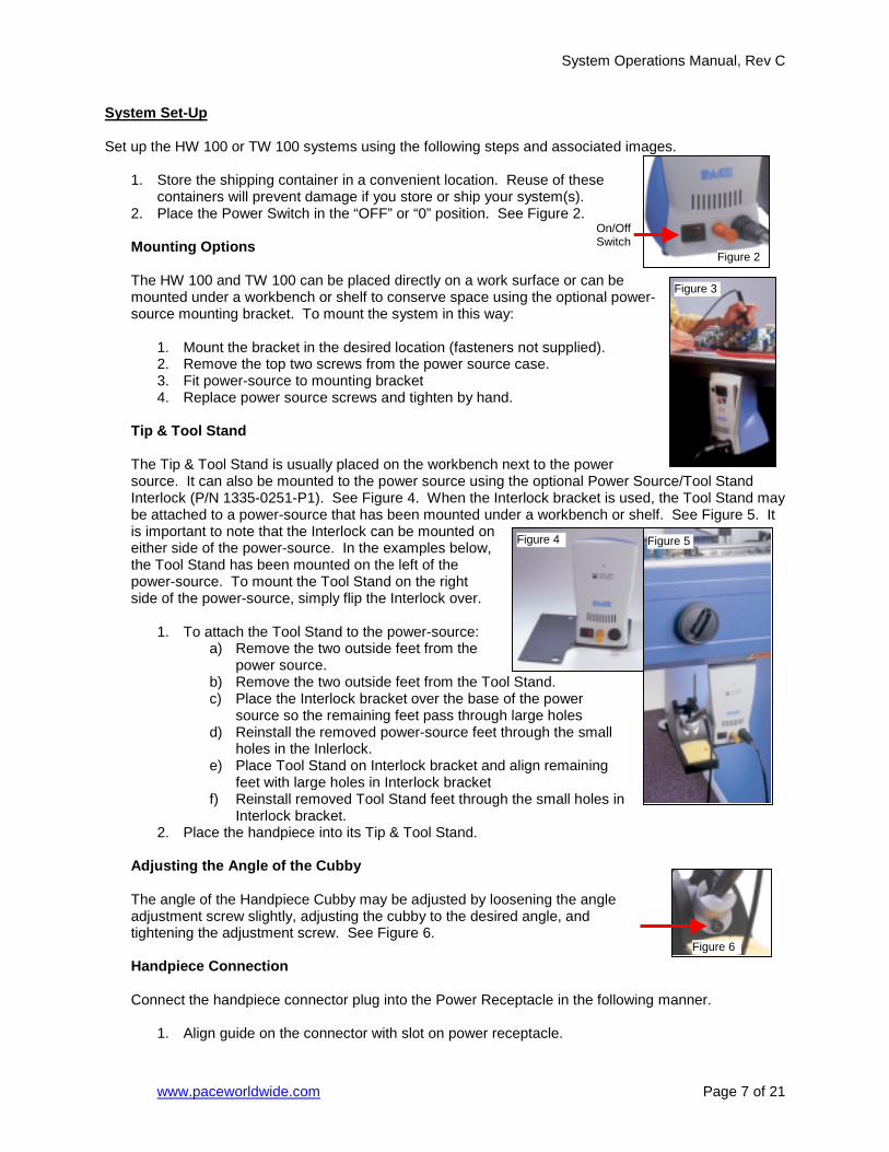
System Set-Up Set up the HW 100 or TW 100 systems using the following steps and associated images.
1. Store the shipping container in a convenient location. Reuse of these
containers will prevent damage if you store or ship your system(s). 2. Place the Power Switch in the “OFF” or “0” position. See Figure 2.
Mounting Options
The HW 100 and TW 100 can be placed directly on a work surface or canmounted under a workbench or shelf to conserve space using the optionasource mounting bracket. To mount the system in this way:
1. Mount the bracket in the desired location (fasteners not supplied2. Remove the top two screws from the power source case. 3. Fit power-source to mounting bracket 4. Replace power source screws and tighten by hand.
Tip & Tool Stand
The Tip & Tool Stand is usually placed on the workbench next to the powsource. It can also be mounted to the power source using the optional PInterlock (P/N 1335-0251-P1). See Figure 4. When the Interlock brackebe attached to a power-source that has been mounted under a workbencis important to note that the Interlock can be mounted on either side of the power-source. In the examples below, the Tool Stand has been mounted on the left of the power-source. To mount the Tool Stand on the right side of the power-source, simply flip the Interlock over.
1. To attach the Tool Stand to the power-source:
a) Remove the two outside feet from the power source.
b) Remove the two outside feet from the Tool Stand. c) Place the Interlock bracket over the base of the power
source so the remaining feet pass through large holes d) Reinstall the removed power-source feet through the sm
holes in the Inlerlock. e) Place Tool Stand on Interlock bracket and align remainin
feet with large holes in Interlock bracket f) Reinstall removed Tool Stand feet through the small hole
Interlock bracket. 2. Place the handpiece into its Tip & Tool Stand.
Adjusting the Angle of the Cubby
The angle of the Handpiece Cubby may be adjusted by loosening the anadjustment screw slightly, adjusting the cubby to the desired angle, and tightening the adjustment screw. See Figure 6.
Handpiece Connection
Connect the handpiece connector plug into the Power Receptacle in the
1. Align guide on the connector with slot on power receptacle.
Figure 4
On/Off Switch
Page 7 of 21
be l power-
).
er ower Source/Tool Stand t is used, the Tool Stand may h or shelf. See Figure 5. It
all
g
s in
gle
following manner.
Figure 6
Figure 5
Figure 3
Figure 2
System Operations Manual, Rev C
www.paceworldwide.com Page 8 of 21
2. Insert connector into power receptacle. 3. Turn the connector housing clockwise to lock in place.
System Power Up
1. Insert the female end of the power cord into the AC Power Receptacle on the rear panel of the power source.
2. Plug the prong end (male end) of the power cord into an appropriate 3 wire grounded AC supply receptacle.
CAUTION: To insure operator and ESD/EOS safety, the AC power supply receptacle must be checked for proper grounding before initial operation.
NOTE: Ensure that the system is placed in a well-ventilated area. Fume extraction equipment is recommended
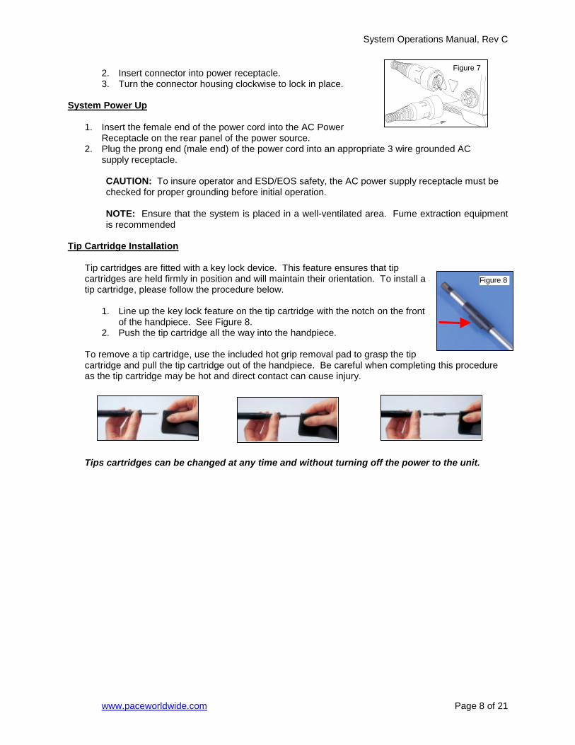
Tip Cartridge Installation
Tip cartridges are fitted with a key lock device. This feature ensures that tip cartridges are held firmly in position and will maintain their orientation. To install a tip cartridge, please follow the procedure below.
1. Line up the key lock feature on the tip cartridge with the notch on the front of the handpiece. See Figure 8.
2. Push the tip cartridge all the way into the handpiece.
To remove a tip cartridge, use the included hot grip removal pad to grasp the tip cartridge and pull the tip cartridge out of the handpiece. Be careful when completing this procedure as the tip cartridge may be hot and direct contact can cause injury.
Tips cartridges can be changed at any time and without turning off the power to the unit.
Figure 7
Figure 8

System Operations Manual, Rev C
www.paceworldwide.com Page 9 of 21
Operation
Definitions Please read and become familiar with the definitions of each of the following terms that are used repeatedly in the following operational procedures.
Auto-Off: Safety feature that turns power off (10-90 minutes, settable in 10 minute increments) after the system has entered Temperature Setback. Normal Operation: Normal operating mode of the system in which the Operating Tip Temperature is displayed. Password: The Password feature of the TW 100 system will prevent unauthorized alteration of stored system temperature parameters and feature settings. If a Password has been installed, the LED Display will display an instruction to enter the Password (a 3 digit number selected using the scroll up/down keys on the system front panel) when a setting change is attempted. Programming Menu: The interface used to program the system features parameters (e.g., temperature limits, password, setback time). Set Tip Temperature: The operator selected idle tip temperature entered into the system memory. Temperature Adjust Mode: Mode of operation where the Set Tip Temperature may be adjusted. Temperature Setback: System feature that will independently set back the Set Tip Temperature to 177°C (350°F) after a user selected or preset period of handpiece inactivity.
HW 100 Heat Wise System The HW 100 requires the use of a Power Module. The Power Module selects the desired heat level for operation. The HW 100 comes standard with three Power Modules, Heat Levels 5, 6, & 7. Additional Power Modules are available in heat levels of 5.5, 6.5, 7.5, and 8. Please refer to the Accessory Section for Power Module part numbers. A heat level of 5 corresponds to a nominal temperature of 500 °F; a heat level of 6.5 corresponds to a temperature of 650 °F, etc. Actual temperatures may vary slightly due to tip geometry. Verify the following:
a) Handpiece connection to the power source. b) Power cord connection between an appropriate AC supply
receptacle and the power source. If the power is turned on while a Power Module is not installed, or if the Power Module is removed during operation, the system will turn itself off and the LED indicator light on the front panel will turn red. See Figure 9. To operate the unit, please make sure the set-up procedure has been followed. Then follow the procedure below.
1. Install the desired Tip Cartridge. 2. Install the desired Power Module into the Power Port on the front of the unit. 3. The LED indicator will turn amber while the tip is heating to the desired performance level.
Figure 9
Power Module
LED Indicator
System Operations Manual, Rev C
www.paceworldwide.com
4. Once the tip has reached the desired heat level, the LED indicator will turn green and the system is ready to use.
The HW 100 system comes standard with an Auto-Setback and Auto-Off Features. These are pre-programmed for 30 minute SetBack and 30 minute Auto Off, which can be turned off by the switch on the bottom of the unit. When Setback mode has been entered, the heat level will be adjusted to 3.5. TW 100 TempWise System
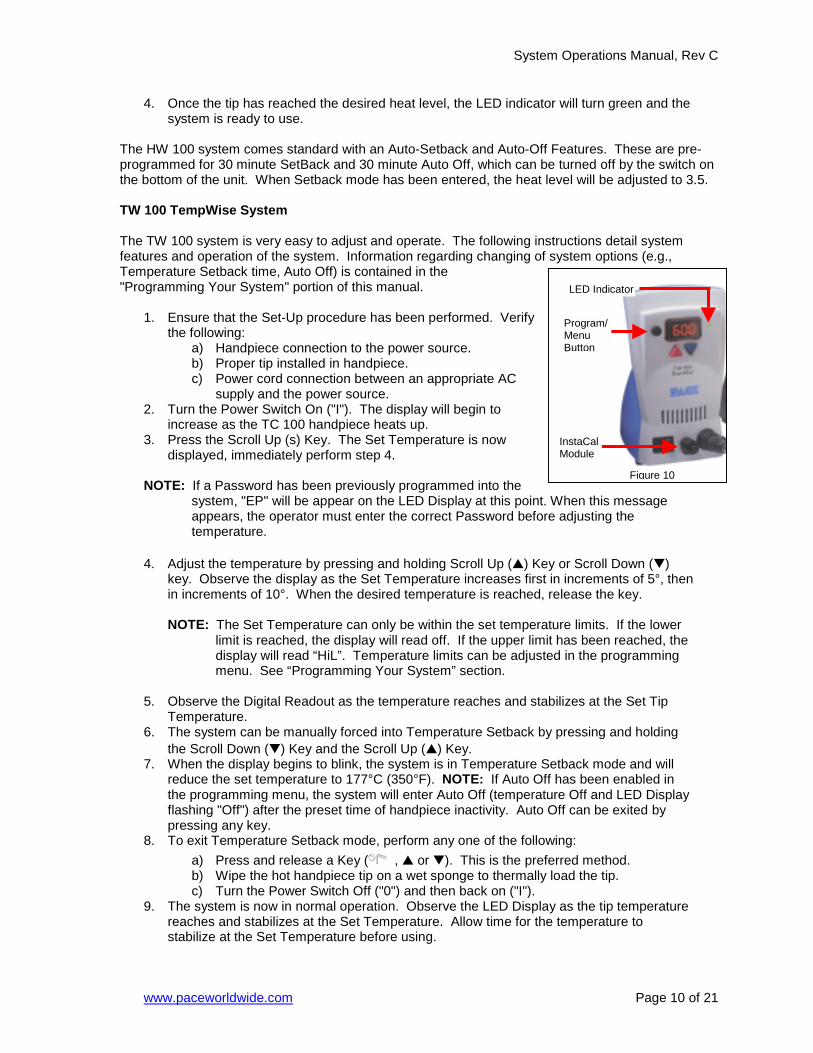
The TW 100 system is very easy to adjust and operate. The following instructions detail system features and operation of the system. Information regarding changing of system options (e.g., Temperature Setback time, Auto Off) is contained in the "Programming Your System" portion of this manual.
1. Ensure that the Set-Up procedure has been performed. Verify
the following: a) Handpiece connection to the power source. b) Proper tip installed in handpiece. c) Power cord connection between an appropriate AC
supply and the power source. 2. Turn the Power Switch On ("I"). The display will begin to
increase as the TC 100 handpiece heats up. 3. Press the Scroll Up (s) Key. The Set Temperature is now
displayed, immediately perform step 4.
NOTE: If a Password has been previously programmed into the system, "EP" will be appear on the LED Display at this point. When this meappears, the operator must enter the correct Password before adjusting thetemperature.
4. Adjust the temperature by pressing and holding Scroll Up (▲) Key or Scroll Dow
key. Observe the display as the Set Temperature increases first in increments in increments of 10°. When the desired temperature is reached, release the ke NOTE: The Set Temperature can only be within the set temperature limits. If t
limit is reached, the display will read off. If the upper limit has been readisplay will read “HiL”. Temperature limits can be adjusted in the progrmenu. See “Programming Your System” section.
5. Observe the Digital Readout as the temperature reaches and stabilizes at the S
Temperature. 6. The system can be manually forced into Temperature Setback by pressing and
the Scroll Down (▼) Key and the Scroll Up (▲) Key. 7. When the display begins to blink, the system is in Temperature Setback mode a
reduce the set temperature to 177°C (350°F). NOTE: If Auto Off has been enathe programming menu, the system will enter Auto Off (temperature Off and LEflashing "Off") after the preset time of handpiece inactivity. Auto Off can be exitpressing any key.
8. To exit Temperature Setback mode, perform any one of the following: a) Press and release a Key ( , ▲ or ▼). This is the preferred method. b) Wipe the hot handpiece tip on a wet sponge to thermally load the tip. c) Turn the Power Switch Off ("0") and then back on ("I").
9. The system is now in normal operation. Observe the LED Display as the tip temreaches and stabilizes at the Set Temperature. Allow time for the temperature stabilize at the Set Temperature before using.
F
LED Indicator
I M
igure 10
nstaCalodule
Program/ Menu Button
Page 10 of 21
ssage
n (▼) of 5°, then y.
he lower ched, the amming
et Tip
holding
nd will bled in D Display ed by
perature to
System Operations Manual, Rev C
www.paceworldwide.com Page 11 of 21
NOTE: Read the “Programming Your System” sections of this manual to utilize the full capabilities of the system.
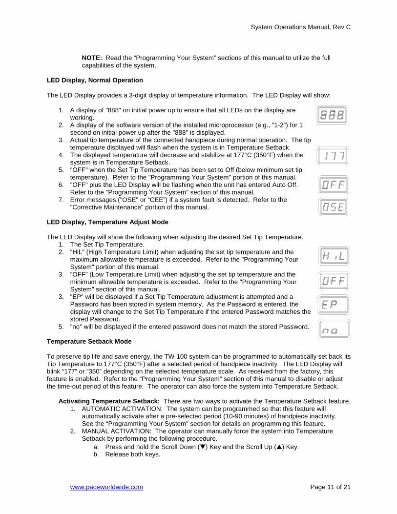
LED Display, Normal Operation The LED Display provides a 3-digit display of temperature information. The LED Display will show:
1. A display of "888" on initial power up to ensure that all LEDs on the display are working.
2. A display of the software version of the installed microprocessor (e.g., "1-2") for 1 second on initial power up after the "888" is displayed.
3. Actual tip temperature of the connected handpiece during normal operation. The tip temperature displayed will flash when the system is in Temperature Setback.
4. The displayed temperature will decrease and stabilize at 177°C (350°F) when the system is in Temperature Setback.
5. "OFF" when the Set Tip Temperature has been set to Off (below minimum set tip temperature). Refer to the "Programming Your System" portion of this manual.
6. "OFF" plus the LED Display will be flashing when the unit has entered Auto Off. Refer to the "Programming Your System" section of this manual.
7. Error messages ("OSE" or “CEE”) if a system fault is detected. Refer to the "Corrective Maintenance" portion of this manual.
LED Display, Temperature Adjust Mode The LED Display will show the following when adjusting the desired Set Tip Temperature.
1. The Set Tip Temperature. 2. "HiL" (High Temperature Limit) when adjusting the set tip temperature and the
maximum allowable temperature is exceeded. Refer to the "Programming Your System" portion of this manual.
3. "OFF" (Low Temperature Limit) when adjusting the set tip temperature and the minimum allowable temperature is exceeded. Refer to the "Programming Your System" section of this manual.
3. "EP" will be displayed if a Set Tip Temperature adjustment is attempted and a Password has been stored in system memory. As the Password is entered, the display will change to the Set Tip Temperature if the entered Password matches the stored Password.
5. "no" will be displayed if the entered password does not match the stored Password. Temperature Setback Mode To preserve tip life and save energy, the TW 100 system can be programmed to automatically set back its Tip Temperature to 177°C (350°F) after a selected period of handpiece inactivity. The LED Display will blink “177” or “350” depending on the selected temperature scale. As received from the factory, this feature is enabled. Refer to the “Programming Your System” section of this manual to disable or adjust the time-out period of this feature. The operator can also force the system into Temperature Setback.
Activating Temperature Setback: There are two ways to activate the Temperature Setback feature. 1. AUTOMATIC ACTIVATION: The system can be programmed so that this feature will
automatically activate after a pre-selected period (10-90 minutes) of handpiece inactivity. See the “Programming Your System” section for details on programming this feature.
2. MANUAL ACTIVATION: The operator can manually force the system into Temperature Setback by performing the following procedure.
a. Press and hold the Scroll Down (▼) Key and the Scroll Up (▲) Key. b. Release both keys.

System Operations Manual, Rev C
www.paceworldwide.com Page 12 of 21
Exiting Temperature Setback: Listed below are 3 ways to exit Temperature Setback. 1. Press and release any key on the front panel (( , ▲ or ▼). This is the preferred
method. 2. Wipe the hot handpiece tip on a wet sponge to thermally load the tip. 3. Turn the Power Switch “OFF” (“0”) and then back “ON” (“l”).
Set Tip Temperature values will be restored. For optimum performance, do not attempt to use the attached handpiece until the Set Tip Temperature is achieved and the LED indicator is green.
Auto Off Safety System Mode When enabled, the Auto Off safety system of the TW 100 system turns off the power to the handpiece 10-90 minutes after entering Temperature Setback. When the system has entered Temperature Setback, an Auto Off timer within the system circuitry will start running if Auto Off is turned on in the Programming Menu. When Auto Off has activated, the LED Display will blink “OFF”.
1. If any key is pressed during the selected time out period, the Auto Off timer is reset. The system will return to normal operation.
2. At the end of the time out period, the system will enter Auto Off. Power is turned off to the heater and the LED Display will show a flashing “OFF ” and the LED indicator will turn red.
Exiting Auto Off: Auto Off can be exited; returning to normal operation by:
1. Pressing and releasing any key on the front panel. ( , ▲ or ▼), or 2. By turning the Power Switch OFF (“0”) and then back ON (“l”).
Using the InstaCal Feature The TW 100 features InstaCal calibration. InstaCal allows the user to calibrate using an independent, laser trimmed, Platinum RTD sensor. The system is calibrated so the display matches the measured tip temperature. Calibration can be completed, as often or as little as you like to meet your own internal specifications. The system will prompt the user to calibrate under specific conditions, for example, after a cartridge has been changed. The system indicates whether calibration is required or not through the color of the LED Indicator Light. When the LED Indicator is Green, the system is calibrated and ready for use, when it is Amber, the system may need to be calibrated , and when it is Red, the system should be calibrated. The following chart explains the function of the LED Indicator Light.
LED Indicator Activity
Power On Amber Calibration Complete Green Tip Cartridge Removed
Red
Heater Open Sensor Red System In SetBack Amber or Green* System in Auto-Off Amber or Green* System reactivated after Auto-Off
Amber or Green*
*The LED will be Amber or Green depending on the color when it entered Setback, or Auto Off. Ensure the InstaCal Module has been installed on the front panel of the TW 100. See Figure 11. To calibrate, the tip is tinned with solder and then placed on the InstaCal Module that contains a laser trimmed, platinum RTD sensor. See Figure 11. If necessary, add a small quantity of solder to ensure

System Operations Manual, Rev C
www.paceworldwide.com P
good linkage between tip and sensor. The System will automatically recognize that the InstaCal Module is in use and the LED Display will change to “CAL”. The calibration process will last for approximately 20 to 30 seconds. When completed, the LED Display will change to “CC” for Calibration Complete, and the LED Indicator light will turn green. The system is now ready for use. The temperature can be adjusted, as needed, and does not need to be recalibrated until the tip cartridge has been replaced. Calibration can still be activated when the LED Indicator is green, although it is unnecessary.
NOTE: Before calibration is attempted, the system should be allowed to reach set temperature. After turning on the system or changing tip cartridges, wait for at least 15 seconds before calibrating.
Programming Your System The menu driven LED Display of the TW 100 system allows you to easily customize your system. By accessing the programming menu, you can:
• Enter, remove or change a Password. • Set the Default Temperature scale to °F or °C as desired. • Change the Upper and Lower Temperature limits. • Enable or disable the Temperature Setback feature and adjust the time-out period. • Enable or disable the Auto Off feature and adjust the time-out period. • Enable or disable the Calibration mode.
The following instructions should be performed to familiarize the operator with the system.
Entering the Programming Menu 1. Place Power Switch in the “OFF” (“0”) position. 2. Press and hold the Program Key ( ) while turning on the Power
Switch (“I” position).
Password 3. The LED Display will display the version of the microprocessor and change to re
or "EP". 4. If the display reads "EP", a Password has been stored in system memory. Enter
digit Password (using the scroll up/down keys). If the Password entered is incorappears on the display and the system then returns to normal operation. If this orepeat steps 1 through 5 and enter the correct Password.
5. The LED Display reads "P--". Choose one of the following options: a) Press the Program Key ( ) to keep the currently stored Password (inc
no Password). b) Press and release the Scroll Up (▲) or Scroll Down Key to enter a new
Password. c) Set the display to “000” for no password.
Temperature Scale
6. The LED Display now shows the stored default Temperature Scale (°C or °F temperature shown on LED Display). Choose one of the following:
a) Press the Program Key ( ) to keep the stored default Temperature Scale.
b) Press and release the Scroll Up (s) Key to change the default TemperatuScale. Press and release the Program Key.
Temperature Limits
Figure 11age 13 of 21
ad “P--”
the 3 rect, "no" ccurs,
luding
re

System Operations Manual, Rev C
www.paceworldwide.com Page 14 of 21
7. The LED Display now shows the stored default High ("Hi") Temperature Limit with the display alternating to show "Hi" and the stored limit. Choose one of the following:
a) Press and release the Program Key ( ) to keep the stored High Temperature Limit.
b) Press and release the Scroll Up (▲) Key to increase the stored High Temperature Limit (up to 425°C, (800°F)). Press and release the Program Key to proceed to the next step.
c) Press and release the Scroll Down (▼) Key to decrease the stored High Temperature Limit. Press and release the Program Key to proceed to the next step.
8. The LED Display now shows the stored default Low ("Lo") Temperature Limit with the display alternating to show "Lo" and the stored limit. Choose one of the following:
a) Press and release the Program Key ( ) to keep the stored Low Temperature Limit (260°C, 500°F).
b) Press and release the Scroll Up (▲) Key to increase the stored Low Temperature Limit. Press and release the Program Key to proceed to the next step.
c) Press and release the Scroll Down (▼) Key to decrease the stored Low Temperature Limit. Press and release the Program Key to proceed to the next step.
Temperature Setback
9. The LED Display now shows the stored Temperature Setback time as "S-X" (x=0 thru 9). Time is shown as tens of minutes (e.g., "S-3" equals 30 minutes). A display of "S- 0" indicates that Setback is disabled. Choose one of the following: a) Press and release the Program Key ( ) to keep the currently stored
Temperature Setback time. b) Press and release the Scroll Up (▲) Key to enable and/or increase the stored
Temperature Setback time. Press and release the Program Key to proceed to the next step.
c) Press and release the Scroll Down (▼) Key to decrease or disable the stored Temperature Setback time. Press and release the Program Key to proceed to the next step.
Auto Off
10. The LED Display now shows the stored Auto Off time as "AOx" (x=0 thru 9). Time is shown as tens of minutes (e.g., "AO3" equals 30 minutes). A display of "AO0" indicates that Auto Off is disabled. Choose one of the following: a) Press and release the Program Key ( ) to keep the currently stored Auto Off
time. b) Press and release the Scroll Up (▲) Key to enable and/or increase the Auto Off.
Press and release the Program Key to proceed to the next step. d) Press and release the Scroll Down (▼) Key to decrease or disable the stored
Auto Off time. Press and release the Program Key to proceed to the next step. Cartridge OffSet
11. The LED Display now reads “COS”. This stands for “Cartridge Offset. The offset value can be set anywhere between –45 °C (-50°F) and 38 °C (100 °F) The Cartridge Offset is used to compensate for large SMT tips as they may run slightly cooler than a single point soldering tip. Use the Scroll Up (▲) and Scroll Down (▼) keys to change the value. When
System Operations Manual, Rev C
www.paceworldwide.com Page 15 of 21
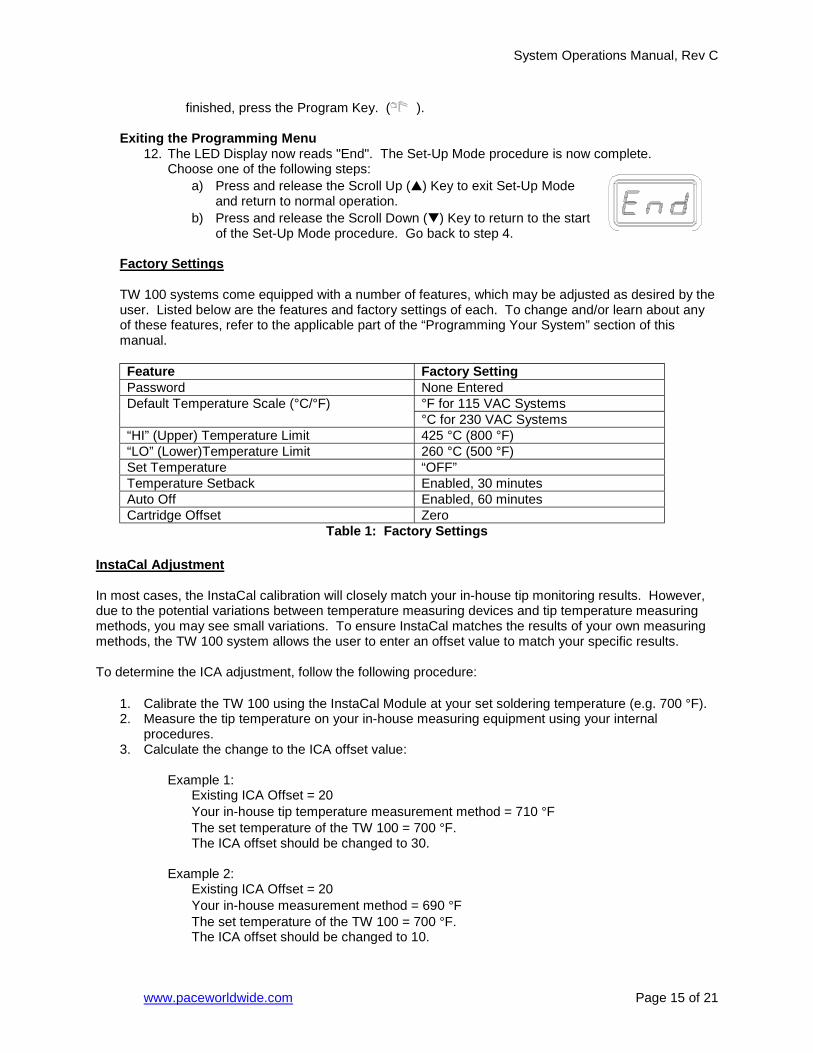
finished, press the Program Key. ( ). Exiting the Programming Menu
12. The LED Display now reads "End". The Set-Up Mode procedure is now complete. Choose one of the following steps:
a) Press and release the Scroll Up (▲) Key to exit Set-Up Mode and return to normal operation.
b) Press and release the Scroll Down (▼) Key to return to the start of the Set-Up Mode procedure. Go back to step 4.
Factory Settings TW 100 systems come equipped with a number of features, which may be adjusted as desired by the user. Listed below are the features and factory settings of each. To change and/or learn about any of these features, refer to the applicable part of the “Programming Your System” section of this manual.
Feature Factory Setting Password None Entered
°F for 115 VAC Systems Default Temperature Scale (°C/°F) °C for 230 VAC Systems
“HI” (Upper) Temperature Limit 425 °C (800 °F) “LO” (Lower)Temperature Limit 260 °C (500 °F) Set Temperature “OFF” Temperature Setback Enabled, 30 minutes Auto Off Enabled, 60 minutes Cartridge Offset Zero
Table 1: Factory Settings InstaCal Adjustment In most cases, the InstaCal calibration will closely match your in-house tip monitoring results. However, due to the potential variations between temperature measuring devices and tip temperature measuring methods, you may see small variations. To ensure InstaCal matches the results of your own measuring methods, the TW 100 system allows the user to enter an offset value to match your specific results. To determine the ICA adjustment, follow the following procedure:
1. Calibrate the TW 100 using the InstaCal Module at your set soldering temperature (e.g. 700 °F). 2. Measure the tip temperature on your in-house measuring equipment using your internal
procedures. 3. Calculate the change to the ICA offset value:
Example 1:
Existing ICA Offset = 20 Your in-house tip temperature measurement method = 710 °F The set temperature of the TW 100 = 700 °F. The ICA offset should be changed to 30.
Example 2: Existing ICA Offset = 20 Your in-house measurement method = 690 °F The set temperature of the TW 100 = 700 °F. The ICA offset should be changed to 10.
System Operations Manual, Rev C
www.paceworldwide.com Page 16 of 21
The ICA offset also allows for improvements to be made to the InstaCal Module without losing backwards compatibility with all existing systems. All InstaCal modules are shipped with an ICA Offset value. When the new InstaCal module in installed, the ICA offset value of the new module should be compared to the value already stored in the system and modified if necessary. To access the InstaCal Adjustment (ICA) offset follow the procedure below:
1. With the power turned off, press and hold the program button ( ) and the up key (▲). 2. Turn on the power switch. The LED Display will show the software version (e.g. 1-2) then will
begin to flash between “ICA” and the entered ICA off set value. NOTE: If a password has been entered into the system, the LED Display will first show
“EPO” and the password must be entered before access to the ICA offset is granted. 3. Using the up and down keys, adjust the ICA offset as needed. 4. Press the program key ( ) to exit the ICA menu and resume normal operation.
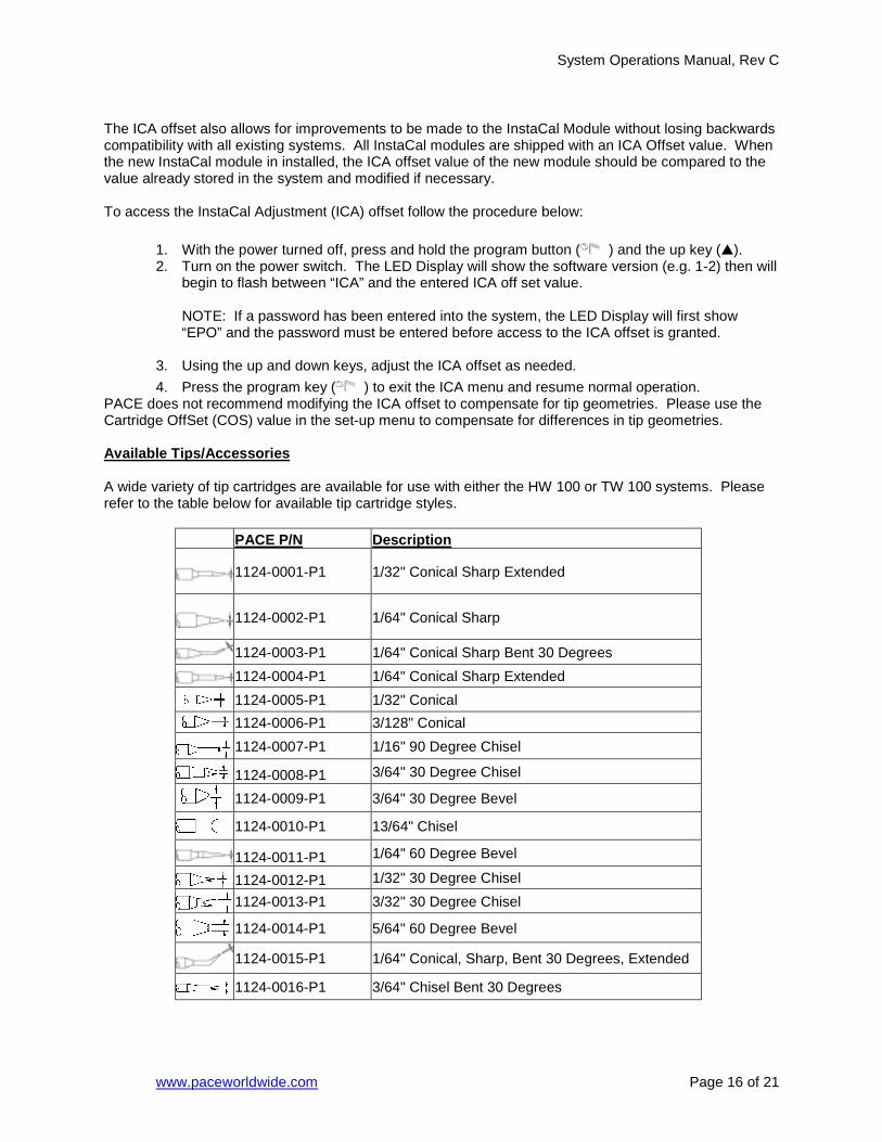
PACE does not recommend modifying the ICA offset to compensate for tip geometries. Please use the Cartridge OffSet (COS) value in the set-up menu to compensate for differences in tip geometries. Available Tips/Accessories A wide variety of tip cartridges are available for use with either the HW 100 or TW 100 systems. Please refer to the table below for available tip cartridge styles.
PACE P/N Description
1124-0001-P1 1/32" Conical Sharp Extended
1124-0002-P1 1/64" Conical Sharp
1124-0003-P1 1/64" Conical Sharp Bent 30 Degrees 1124-0004-P1 1/64" Conical Sharp Extended
1124-0005-P1 1/32" Conical
1124-0006-P1 3/128" Conical
1124-0007-P1 1/16" 90 Degree Chisel
1124-0008-P1 3/64" 30 Degree Chisel
1124-0009-P1 3/64" 30 Degree Bevel
1124-0010-P1 13/64" Chisel
1124-0011-P1 1/64" 60 Degree Bevel
1124-0012-P1 1/32" 30 Degree Chisel
1124-0013-P1 3/32" 30 Degree Chisel
1124-0014-P1 5/64" 60 Degree Bevel
1124-0015-P1 1/64" Conical, Sharp, Bent 30 Degrees, Extended
1124-0016-P1 3/64" Chisel Bent 30 Degrees
System Operations Manual, Rev C
www.paceworldwide.com Page 17 of 21
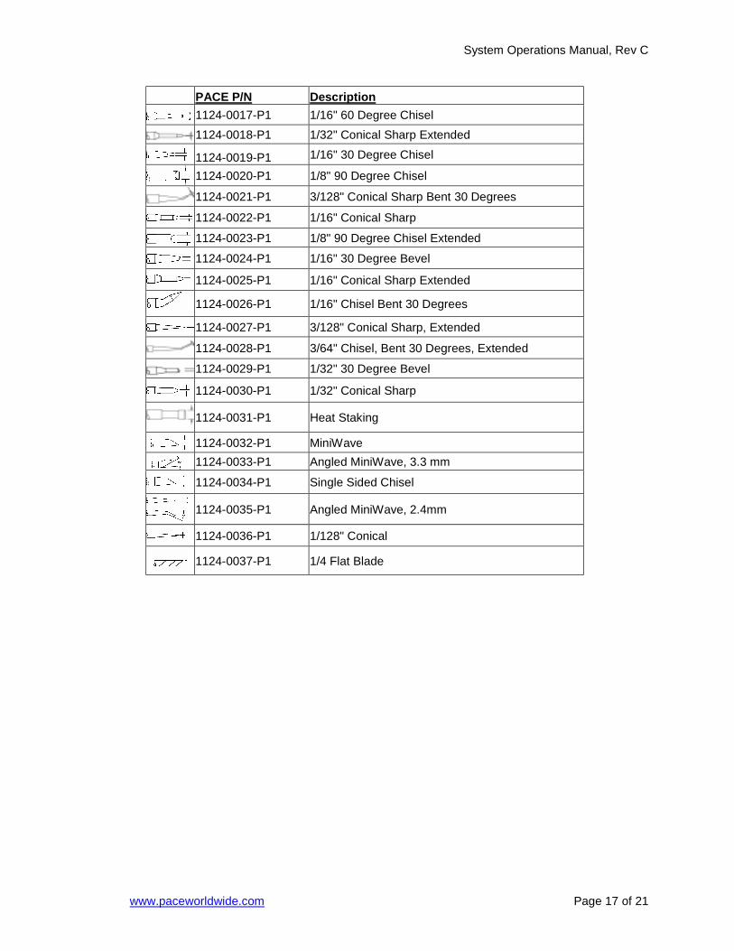
PACE P/N Description
1124-0017-P1 1/16" 60 Degree Chisel 1124-0018-P1 1/32" Conical Sharp Extended
1124-0019-P1 1/16" 30 Degree Chisel
1124-0020-P1 1/8" 90 Degree Chisel
1124-0021-P1 3/128" Conical Sharp Bent 30 Degrees
1124-0022-P1 1/16" Conical Sharp
1124-0023-P1 1/8" 90 Degree Chisel Extended
1124-0024-P1 1/16" 30 Degree Bevel
1124-0025-P1 1/16" Conical Sharp Extended
1124-0026-P1 1/16" Chisel Bent 30 Degrees
1124-0027-P1 3/128" Conical Sharp, Extended
1124-0028-P1 3/64" Chisel, Bent 30 Degrees, Extended
1124-0029-P1 1/32" 30 Degree Bevel
1124-0030-P1 1/32" Conical Sharp
1124-0031-P1 Heat Staking
1124-0032-P1 MiniWave
1124-0033-P1 Angled MiniWave, 3.3 mm
1124-0034-P1 Single Sided Chisel
1124-0035-P1 Angled MiniWave, 2.4mm
1124-0036-P1 1/128" Conical
1124-0037-P1 1/4 Flat Blade
System Operations Manual, Rev C
www.paceworldwide.com Page 18 of 21
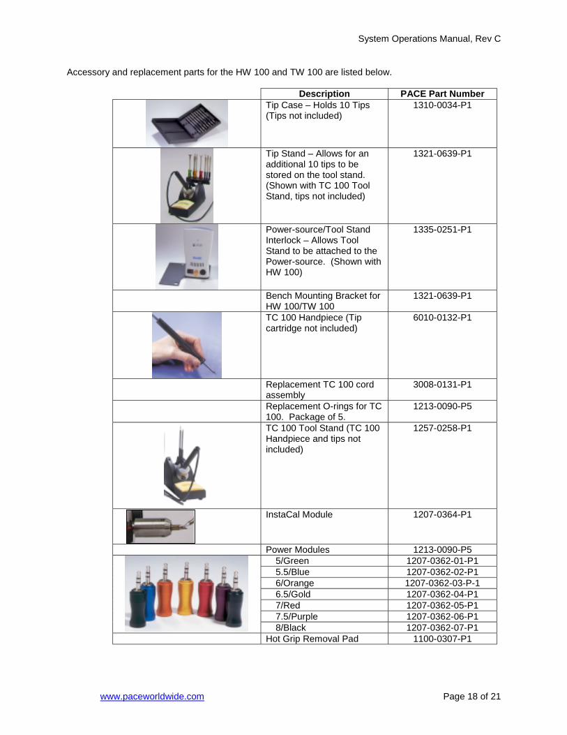
Accessory and replacement parts for the HW 100 and TW 100 are listed below.
Description PACE Part Number
Tip Case – Holds 10 Tips (Tips not included)
1310-0034-P1
Tip Stand – Allows for an additional 10 tips to be stored on the tool stand. (Shown with TC 100 Tool Stand, tips not included)
1321-0639-P1
Power-source/Tool Stand Interlock – Allows Tool Stand to be attached to the Power-source. (Shown with HW 100)
1335-0251-P1
Bench Mounting Bracket for HW 100/TW 100
1321-0639-P1
TC 100 Handpiece (Tip cartridge not included)
6010-0132-P1
Replacement TC 100 cord assembly
3008-0131-P1
Replacement O-rings for TC 100. Package of 5.
1213-0090-P5
TC 100 Tool Stand (TC 100 Handpiece and tips not included)
1257-0258-P1
InstaCal Module 1207-0364-P1
Power Modules 1213-0090-P5 5/Green 1207-0362-01-P1 5.5/Blue 1207-0362-02-P1 6/Orange 1207-0362-03-P-1 6.5/Gold 1207-0362-04-P1 7/Red 1207-0362-05-P1 7.5/Purple 1207-0362-06-P1
8/Black 1207-0362-07-P1 Hot Grip Removal Pad 1100-0307-P1
System Operations Manual, Rev C
ww
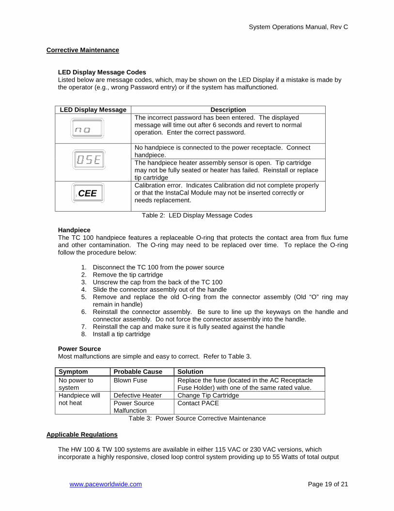
Corrective Maintenance
LED Display Message Codes Listed below are message codes, which, may be shown on the LED Display if a mistake is made by the operator (e.g., wrong Password entry) or if the system has malfunctioned. LED Display Message Description
The incorrect password has been entered. The displayed message will time out after 6 seconds and revert to normal operation. Enter the correct password. No handpiece is connected to the power receptacle. Connect handpiece.
The handpiece heater assembly sensor is open. Tip cartridge may not be fully seated or heater has failed. Reinstall or replace tip cartridge
Calibration error. Indicates Calibration did not complete properly or that the InstaCal Module may not be inserted correctly or
HandpThe TCand othfollow t
Power Most m
SymptNo powsystemHandpinot hea
Applicable
The HWincorpo
E
CEw.paceworldwide.com Page 19 of 21
needs replacement.
Table 2: LED Display Message Codes
iece 100 handpiece features a replaceable O-ring that protects the contact area from flux fume er contamination. The O-ring may need to be replaced over time. To replace the O-ring
he procedure below:
1. Disconnect the TC 100 from the power source 2. Remove the tip cartridge 3. Unscrew the cap from the back of the TC 100 4. Slide the connector assembly out of the handle 5. Remove and replace the old O-ring from the connector assembly (Old “O” ring may
remain in handle) 6. Reinstall the connector assembly. Be sure to line up the keyways on the handle and
connector assembly. Do not force the connector assembly into the handle. 7. Reinstall the cap and make sure it is fully seated against the handle 8. Install a tip cartridge
Source alfunctions are simple and easy to correct. Refer to Table 3.
om Probable Cause Solution er to
Blown Fuse Replace the fuse (located in the AC Receptacle Fuse Holder) with one of the same rated value.
Defective Heater Change Tip Cartridge ece will t Power Source
Malfunction Contact PACE
Table 3: Power Source Corrective Maintenance
Regulations
100 & TW 100 systems are available in either 115 VAC or 230 VAC versions, which rate a highly responsive, closed loop control system providing up to 55 Watts of total output
System Operations Manual, Rev C
www.paceworldwide.com Page 20 of 21
power. The 230 VAC version system bears the CE Conformity Marking, which assures the user that it conforms to EMC 89/336/EEC. The 115 VAC version systems conform to FCC Emission Control Standard, Title 47, Subpart B, Class A. This standard is designed to provide reasonable protection against harmful interference when the equipment is operated in a commercial environment.
Service & Warranty
Please contact PACE or your local distributor for service and repair.
LIMITED WARRANTY Seller warrants to the first user that products manufactured by it and supplied hereunder are free of defects in materials and workmanship for a period of three (3) years from the date of receipt by such user. Blowers and motor pumps (which wear out during normal use) are warranted for a period of one (1) year. This warranty does not cover wear and tear under normal use, repair or replacement required as a result of misuse, improper application, mishandling or improper storage. Consumable items such as tips, heaters, filters, etc. which wear out under normal use are excluded. Failure to perform recommended routine maintenance, alterations or repairs made other than in accordance with Seller’s directions, or removal or alteration of identification plates in any way will void this warranty. This warranty is available only to the first user, but the exclusions and limitations herein apply to all persons and entities. SELLER MAKES NO OTHER WARRANTY, EXPRESS OR IMPLIED, AND MAKES NO WARRANTY OF MERCHANTABILITY OR FITNESS FOR A PARTICULAR PURPOSE. Seller will, at its option, repair or replace any defective products at its facility or other location approved by it at no charge to user, or provide parts without charge for installation by the user in the field at user’s expense and risk. User will be responsible for all costs of shipping equipment to Seller or other location for warranty service. EXCEPT FOR THE REMEDY ABOVE DESCRIBED, UNLESS OTHERWISE REQUIRED BY APPLICABLE LAW, SELLER WILL HAVE NO OTHER OBLIGATION WITH REGARD TO ANY BREACH OF WARRANTY OR OTHER CLAIM WITH RESPECT TO THE PRODUCTS, OR LIABILITY FOR ANY DIRECT, INDIRECT, CONSEQUENTIAL, OR INCIDENTAL LOSS OR DAMAGE CAUSED BY OR OCCURRING IN CONNECTION WITH ANY OF THE PRODUCTS. Warranty service may be obtained by contacting the appropriate PACE Company or local Authorized PACE distributor as set forth below to determine if return of any item is required, or if repairs can be made by the user in the field. Defective products may not be returned to PACE without a Service Authorization (“SA”) Number. Any warranty or other claim with respect to the products must be made in writing delivered to PACE (or local Authorized PACE distributor for Buyers outside the USA and the United Kingdom) within a reasonable time of the expiration date of this warranty with sufficient evidence of purchase and date of receipt, otherwise user’s rights under this warranty shall be deemed waived.

System Operations Manual, Rev C
www.paceworldwide.com Page 21 of 21
PACE Incorporated retains the right to make changes to specifications contained herein at any time, without notice. Contact your local authorized PACE Distributor or PACE Incorporated to obtain the latest specifications. The following are trademarks and/or service marks of PACE, Incorporated, MD, USA:
INSTACAL , FUMEFLO , HEATWISE , PACEWORLDWIDE , PERMAGROUND , POWERPORT , POWERMODULE , and TEMPWISE .
The following are registered trademarks and/or service marks of PACE Incorporated, Laurel Maryland U.S.A.
ARM-EVAC , FLO-D-SODR , MINIWAVE , PACE , SENSATEMP , SNAP-VAC , SODRTEK , SODR-X-TRACTOR , THERMOFLO , THERMOJET , THERMOTWEEZ , and VISIFILTER .
PACE products meet or exceed all applicable military and civilian EOS/ESD, temperature stability and other specifications including MIL STD 2000, ANSI/JSTD 001, IPC7711, and IPC A-610.
PACE USA PACE Europe 9893 Brewers Court Sherbourne House Laurel, MD 20723 Sherbourne Drive USA Tilbrook, Milton Keynes MK7 8HX United Kingdom Tel: (301) 490-9860 (44) 1908-277666 Fax: (301) 498-3252 (44) 1908-277777