Embed Size (px)
Citation preview

1
Operation and Maintenance Instructions Geared Head Bench Lathe Model GHB-1236
JET 427 New Sanford Road LaVergne, Tennessee 37086 Part No. M-321236 Ph.: 800-274-6848 Edition 1 04/2017 www.jettools.com Copyright © 2017 JET

1.0 IMPORTANT SAFETY INSTRUCTIONS
Read and understand the entire owner's manual before attempting set-up or operation of this lathe.
1. This machine is designed and intended for use by properly trained and experienced personnel only. If you are not familiar with the proper and safe use of lathes, do not use this machine until proper training and knowledge have been obtained.
2. Keep guards in place. Safety guards must be kept in place and in working order.
3. Remove adjusting keys and wrenches. Before turning on machine, check to see that any adjusting wrenches are removed from the tool.
4. Reduce the risk of unintentional starting. Make sure switch is in the OFF position before plugging in the tool.
5. Do not force tools. Always use a tool at the rate for which it was designed.
6. Use the right tool. Do not force a tool or attachment to do a job for which it was not designed.
7. Maintain tools with care. Keep tools sharp and clean for best and safest performance. Follow instructions for lubrication and changing accessories.
8. Always disconnect the tool from the power source before adjusting or servicing.
9. Check for damaged parts. Check for alignment of moving parts, breakage of parts, mounting, and any other condition that may affect the tool’s operation. A guard or any part that is damaged should be repaired or replaced.
10. Turn power off. Never leave a tool unattended. Do not leave a tool until it comes to a complete stop.
11. Keep work area clean. Cluttered areas and benches invite accidents.
12. Do not use in a dangerous environment. Do not use power tools in damp or wet locations, or expose them to rain. Keep work area well lighted.
13. Keep children and visitors away. All visitors should be kept a safe distance from the work area.
14. Make the workshop child proof. Use padlocks, master switches, and remove starter keys.
15. Wear proper apparel. Loose clothing, gloves, neckties, rings, bracelets, or other jewelry may get caught in moving parts. Non-slip footwear is recommended. Wear protective hair covering to contain long hair. Do not wear any type of glove.
16. Always use safety glasses. Every day glasses only have impact resistant lenses; they are not safety glasses.
17. Do not overreach. Keep proper footing and balance at all times.
18. Do not place hands near the chuck while the machine is operating.
19. Do not perform any set-up work while machine is operating.
20. Read and understand all warnings posted on the machine.
21. This manual is intended to familiarize you with the technical aspects of this lathe. It is not, nor was it intended to be, a training manual.
22. CALIFORNIA PROPOSITION 65 WARNING: This product contains chemicals known to the State of California to cause cancer, or birth defects or other reproductive harm.
23. This product, when used for welding, cutting, or working with metal, produces fumes, gases, or dusts which contain chemicals known to the State of California to cause birth defects and, in some cases, cancer. (California Health and Safety Code Section 25249.5 et seq.)
24. Do not attempt to adjust or remove tools during operation.
25. Never stop a rotating chuck or workpiece with your hands.
26. Choose a low spindle speed when working unbalanced workpieces, and for threading and tapping operations.
27. Do not exceed the maximum speed of the workholding device.
28. Do not exceed the clamping capacity of the chuck.
29. Workpieces longer than 3 times the chucking diameter must be supported by the tailstock or a steady rest.
30. Avoid small chuck diameters with large turning diameters.
31. Avoid short chucking lengths and small chucking contact.
32. Turn off the machine and disconnect from power before cleaning. Use a brush to remove shavings or debris — do not use your hands.

3
33. Do not stand on the machine. Serious injury could occur if the machine tips over.
34. Never leave the machine running unattended. Turn the power off and do not leave the machine until moving parts come to a complete stop.
35. Remove loose items and unnecessary work pieces from the area before starting the machine.
36. Do not operate the lathe in flammable or explosive environments. Do not use in a damp environment or expose to rain.
Familiarize yourself with the following safety notices used in this manual:
This means that if precautions are not heeded, it may result in minor injury and/or possible machine damage.
This means that if precautions are not heeded, it may result in serious, or possibly even fatal, injury.
2.0 About this manual This manual is provided by JET, covering the safe operation and maintenance procedures for a JET Model GHB-1236 Lathe. This manual contains instructions on installation, safety precautions, general operating procedures, and maintenance instructions. Your machine has been designed and constructed to provide consistent, long-term operation if used in accordance with the instructions as set forth in this document.
This manual is not intended to be a training guide for lathe operations, or tool and workpiece selection. Consult a machinery handbook or shop supervisor for information on proper speed and feed rates for specific materials, or type of cutter suitable for a particular operation. Whatever accepted methods or materials are used, always make personal safety a priority.
If there are questions or comments, please contact your local supplier or JET. JET can also be reached at our web site: www.jettools.com.
Retain this manual for future reference. If the machine transfers ownership, the manual should accompany it.
Read and understand the entire contents of this manual before attempting assembly or operation! Failure to comply may cause serious injury!
Register your product using the mail-in card provided, or register online: http://www.jettools.com/us/en/service-and-support/warranty/registration/

3.0 Table of contents Section Page 1.0 IMPORTANT SAFETY INSTRUCTIONS ....................................................................................................... 2 2.0 About this manual .......................................................................................................................................... 3 3.0 Table of contents ............................................................................................................................................ 4 4.0 Specifications ................................................................................................................................................. 6
4.1 Dimensions for provided stand ................................................................................................................... 7 5.0 Setup and assembly ....................................................................................................................................... 8
5.1 Shipping contents ....................................................................................................................................... 8 5.2 Uncrating and cleanup ............................................................................................................................... 9 5.3 Chuck preparation (three jaw) .................................................................................................................... 9 5.4 Chuck guard installation ........................................................................................................................... 10
6.0 Lubrication .................................................................................................................................................... 10 7.0 Electrical connections .................................................................................................................................. 11
7.1 GROUNDING INSTRUCTIONS ............................................................................................................... 11 7.2 Extension cords ........................................................................................................................................ 12
8.0 General description ...................................................................................................................................... 12 8.1 Lathe bed .................................................................................................................................................. 12 8.2 Carriage .................................................................................................................................................... 12 8.3 Headstock ................................................................................................................................................. 12 8.4 Quick change tool post ............................................................................................................................. 12 8.5 Apron ........................................................................................................................................................ 13 8.6 Tailstock ................................................................................................................................................... 13 8.7 Leadscrew and feed rod ........................................................................................................................... 13 8.8 Gear box ................................................................................................................................................... 13 8.9 Steady rest ............................................................................................................................................... 13 8.10 Follow rest .............................................................................................................................................. 13
9.0 Controls ........................................................................................................................................................ 13 10.0 Operation ................................................................................................................................................... 15
10.1 Break-in procedure ................................................................................................................................. 15 10.2 Feed and thread selection ...................................................................................................................... 15 10.3 Change gear replacement ...................................................................................................................... 15 10.4 Automatic feed operation and feed changes .......................................................................................... 15 10.5 Powered carriage travel ......................................................................................................................... 16 10.6 Thread cutting ........................................................................................................................................ 16
11.0 Adjustments ............................................................................................................................................... 16 11.1 Saddle adjustment .................................................................................................................................. 16 11.2 Cross slide adjustment ........................................................................................................................... 16 11.3 Compound slide adjustment ................................................................................................................... 16 11.4 Tailstock adjustment ............................................................................................................................... 16 11.5 Half nut gib adjustment ........................................................................................................................... 17 11.6 Headstock alignment .............................................................................................................................. 17 11.7 Removing gap bridge ............................................................................................................................. 17 11.8 Installing gap bridge ............................................................................................................................... 17
12.0 Thread and feed chart ................................................................................................................................ 18 13.0 Replacement parts ..................................................................................................................................... 19
13.1.1 Bed Assembly – Exploded View .......................................................................................................... 19 13.1.2 Bed Assembly – Parts List .................................................................................................................. 19 13.2.1 Headstock Assembly – Exploded View ............................................................................................... 20 13.2.2 Headstock Assembly – Parts List ........................................................................................................ 22 13.3.1 Gearbox Assembly – Exploded View .................................................................................................. 24 13.3.2 Gearbox Assembly – Parts List ........................................................................................................... 26 13.4.1 Apron Assembly – Exploded View ...................................................................................................... 28 13.4.2 Apron Assembly – Parts List ............................................................................................................... 29 13.5.1 Cross Slide Assembly – Exploded View .............................................................................................. 31 13.5.2 Cross Slide Assembly – Parts List ...................................................................................................... 32 13.6.1 Compound Rest Assembly – Exploded View ...................................................................................... 33 13.6.2 Compound Rest Assembly – Parts List ............................................................................................... 34 13.7.1 Tailstock Assembly – Exploded View .................................................................................................. 36 13.7.2 Tailstock Assembly – Parts List ........................................................................................................... 37
5
13.8.1 Change Gears – Exploded View ......................................................................................................... 38 13.8.2 Change Gears – Parts List .................................................................................................................. 38 13.9.1 Feed Rod Assembly – Exploded View ................................................................................................ 39 13.9.2 Feed Rod Assembly – Parts List ......................................................................................................... 40 13.10.2 Motor and Change Gear Enclosure – Exploded View ....................................................................... 41 13.10.2 Motor and Change Gear Enclosure – Parts List ................................................................................ 42 13.11.1 Stand/Brake/Coolant Pump – Exploded View ................................................................................... 43 13.11.2 Stand/Brake/Coolant Pump – Parts List ............................................................................................ 45 13.12.1 Electrical Box Assembly – Exploded View ........................................................................................ 46 13.12.2 Electrical Box Assembly – Parts List ................................................................................................. 47 13.13.1 Steady Rest and Follow Rest – Parts List ......................................................................................... 48 13.13.2 Steady Rest and Follow Rest – Parts List ......................................................................................... 49 13.14.1 Chuck and Leadscrew Guards – Exploded View .............................................................................. 50 13.14.2 Chuck and Leadscrew Guards – Parts List ....................................................................................... 50 13.15.1 Accessories – Exploded View ........................................................................................................... 51 13.15.2 Accessories – Parts List .................................................................................................................... 52
14.0 Wiring Diagram for GHB-1236 ................................................................................................................... 53 15.0 Warranty and service ................................................................................................................................. 54

6
4.0 Specifications Table 1
Model number GHB-1236 Stock number 321236 Motor and Electricals Motor type TEFC induction Horsepower 2 HP (1.5 kW) Phase single Voltage 230V only Cycle 60 Hz Listed FLA (full load amps) 8.5 A Start capacitor 150μF 250V Run capacitor 20μF 450V Motor speed 1720 RPM Power cord 16AWG, 3 x 1.31 mm2 Power plug installed n/a Recommended circuit size 1 15 A Sound emission without load 2 88 dB Capacities Swing over bed 13 in. (330 mm) Swing over cross slide 7-1/2 in. (190.5 mm) Distance between centers 33 in. (838 mm) Swing through gap 18 in. (457 mm) Length of gap 8-3/4 in. (222.25 mm) Steady rest capacity 5/16 – 2-15/16 in. (8 – 74.6 mm) Follow rest capacity 2-3/16 in. (55.6 mm) Headstock Hole through spindle 1-9/16 in. (39.7 mm) Spindle nose D1-4 Taper in spindle nose MT5 Spindle taper adaptor MT3 Spindle bearing type Taper roller bearing Number of spindle speeds 9 Range of spindle speeds 75-1400 RPM Leadscrew 7/8 in. x 8 TPI Feed rod diameter 3/4 in. (19 mm) Gearbox Number of longitudinal and cross feed rates 48/36 Range of longitudinal feeds 0.0019 – 0.0472 in./rev Range of cross feeds 0.0014 – 0.0116 in./rev Number of inch threads 36 Range of inch threads 4 – 60 TPI Number of metric threads 32 Range of metric threads 0.4 – 7 mm Compound and carriage Tool post type Quick change Maximum tool size 5/8 x 5/8 in. Maximum compound slide travel 3 in. (76.2 mm) Maximum cross slide travel 5-1/2 in. (140 mm) Maximum carriage travel 27-3/8 in. (695.3 mm)
7
Tailstock Tailstock spindle travel 3-1/2 in. (89 mm) Diameter of tailstock spindle 1-1/4 in. (31.8 mm) Taper in tailstock spindle MT3 Main materials Headstock Cast iron Bed Cast iron Apron/Saddle Cast iron Tailstock Cast iron Splash guard Steel Stand Steel Dimensions Bed width 7-1/8 in. (181 mm) Overall dimensions, L x W x H 66-3/16 x 29-1/2 x 57-1/2 in. (1681 x 749.3 x 1460.5 mm) Shipping dimensions, L x W x H 66-1/2 x 29-9/16 x 57-1/8 in. (1690 x 750 x 1451 mm) Weights Net weight, approx. 1210 lb. (548.8 kg) Shipping weight, approx. 1430 lb. (648.6 kg)
1 subject to local and national electrical codes. 2 The specified values are emission levels and are not necessarily to be seen as safe operating levels. As workplace conditions vary, this information is intended to allow the user to make a better estimation of the hazards and risks involved only.
L = length, W = width, H = height, TPI = threads per inch
n/a = not applicable
The specifications in this manual were current at time of publication, but because of our policy of continuous improvement, JET reserves the right to change specifications at any time and without prior notice, without incurring obligations.
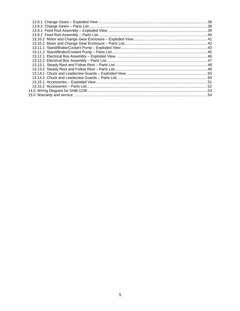
4.1 Dimensions for provided stand
Figure 4-1: stand dimensions

8
5.0 Setup and assembly
5.1 Shipping contents See Figure 5-1.
1 Lathe 1 Steady Rest (mounted on lathe) 1 Follow Rest (mounted on lathe) 1 6" Three Jaw Chuck (mounted on lathe) 1 8" Four Jaw Chuck (strapped to container) 1 10" Face Plate (strapped to container) 1 Tool Box (strapped to container) 1 Chip Tray 1 Splash Guard Tool Box contents: 3 Open End Wrenches (10/12, 14/17, 17/19mm) 1 Oil Gun 1 Hex Key Set (2, 3, 4, 5, 6mm) 1 22T Gear 1 26T Gear 1 38T Gear 1 44T Gear 1 52T Gear 2 MT-3 Dead Centers 1 MT-3 Live Center 1 MT-3 to MT-5 Center Sleeve 1 Cross Point Screwdriver 1 Flat Head Screwdriver 1 Quick Change Tool Holders
(250-202, 250-204, 250, 207, 250-210) 1 Key for 3-Jaw Chuck 1 Key for 4-Jaw Chuck 1 Key for Cam Locks 1 Set of Reverse Jaws for 3-Jaw Chuck 1 Handle for Cross Slide Handwheel 1 Handle for Apron Handwheel 2 V-Belts (A-813) 6 Leveling Pads (with M14x50 Bolts & Washers) 1 Operation and Maintenance Instructions 1 Packing List 1 Test Record 1 Product Registration Card
Figure 5-1

9
5.2 Uncrating and cleanup
Machine is heavy. Use an appropriate lifting device and use extreme caution when moving the machine to its final location. Failure to comply may cause serious injury.
1. Finish removing wooden crate from around lathe.
2. Unbolt lathe from shipping crate bottom.
3. Choose a location for the lathe that is dry, has good lighting, and has enough room to be able to service the lathe on all four sides.
4. Move carriage and tailstock to the tailstock end of the bed.
5. Place two steel rods or pipes of sufficient strength into four holes (A, Figure 5-2) of lathe stand. Sling the lathe with properly rated straps. Do not lift by spindle. With adequate lifting equipment, slowly raise lathe off shipping crate bottom. Make sure lathe is balanced before moving to sturdy bench or optional stand.
Figure 5-2
6. To avoid twisting the bed, the lathe's location must be absolutely flat and level. Bolt lathe to stand (if used). If using a bench, through-bolt for best performance.
7. Clean all rust protected surfaces using a mild commercial solvent, kerosene or diesel fuel. Do not use paint thinner, gasoline, or lacquer thinner, as these will damage painted surfaces. Cover all cleaned surfaces with a light film of Mobil DTE® Oil Heavy Medium or equivalent.
8. Remove end gear cover. Clean all components of end gear assembly and coat all gears with a heavy, non-slinging grease.
9. Using a machinist’s precision level on the bedways, check to make sure lathe is level side to side and front to back. If necessary,
loosen mounting bolts, shim, and retighten mounting bolts. The lathe must be level to be accurate.
5.3 Chuck preparation (three jaw)
Read and understand all directions for chuck preparation. Failure to comply may cause serious injury and/or damage to the lathe.
Note: Before removing chuck from spindle, place a way board across bedways under the chuck.
1. Support the chuck while turning three camlocks 1/4 turn counter-clockwise with the chuck key enclosed in the toolbox. Figure 5-3 shows the cam in the secure position. Line up the two marks (A, Figure 5-3) for removal.
Figure 5-3
2. Carefully remove chuck from spindle and place on an adequate work surface.
3. Inspect the camlock studs. Make sure they have not become cracked or broken during transit. Clean all parts thoroughly with solvent. Also clean spindle and camlocks.
4. Cover all chuck jaws and scroll inside the chuck with Mobilith® AW2. Cover spindle, cam locks, and chuck body with a light film of Mobil DTE® Oil Heavy Medium.
5. Lift chuck up to spindle nose and press onto spindle. Tighten in place by turning cam locks 1/4 turn clockwise. The index mark (A, Figure 5-3) on the camlock should be between the two indicator arrows (B, Figure 5-3). If the index mark is not between the two arrows, remove chuck and adjust the camlock studs by either turning out one full turn (if cams will not engage) or turning in one full turn (if cams turn beyond indicator marks).
6. Install chuck and tighten in place.
ATTENTION: Only when the incised line on chuck lines up with that on the spindle, can the chuck be mounted.

10
5.4 Chuck guard installation Install chuck guard to headstock, if it is not already mounted. (See parts breakdown if clarification is needed for assembly.)
6.0 Lubrication
Lathe must be serviced at all lubrication points and all reservoirs filled to operating level before lathe is placed into service. Failure to comply may cause serious damage to lathe.
1. Headstock – Oil must be up to indicator mark in oil sight glass (A, Figure 6-1). Top off with Mobil DTE® Oil Heavy Medium. Fill by pulling plug located on top of headstock cover beneath rubber mat. Drain oil by removing drain plug (C, Figure 6-2) and refill after first month of operation. Clean out any metal shavings. Then, change oil in headstock annually.
2. External Gears – Coat all gears with a heavy, non-slinging grease, see Figure 6-2. Do not get grease on pulleys or belts.
3. Gear Shaft – Remove set screw (F, Figure 8-2) and oil with a couple drops of Mobil DTE® Oil Heavy Medium once weekly.
4. Gearbox – Oil must be up to indicator mark in oil sight glass (B, Figure 6-1). Top off with Mobil DTE® Oil Heavy Medium. Fill by removing plug (D, Figure 6-2). Drain oil by removing drain plug (E, Figure 6-2) and refill after first month of operation. Then, change oil in gearbox annually.
5. Apron – Oil must be up to indicator mark in oil sight glass (A, Figure 6-3). Top off with Mobil DTE® Oil Heavy Medium. Fill by removing oil plug (B, Figure 6-3). After the first three months of operation, drain oil completely (drain is on bottom of apron) and refill with Mobil DTE® Oil Heavy Medium, or equivalent to the indicator line. Then, change oil annually.
6. Carriage – Lubricate two ball oilers on top of carriage once daily with Mobil DTE® Oil Heavy Medium.
Figure 6-1
Figure 6-2
Figure 6-3
11
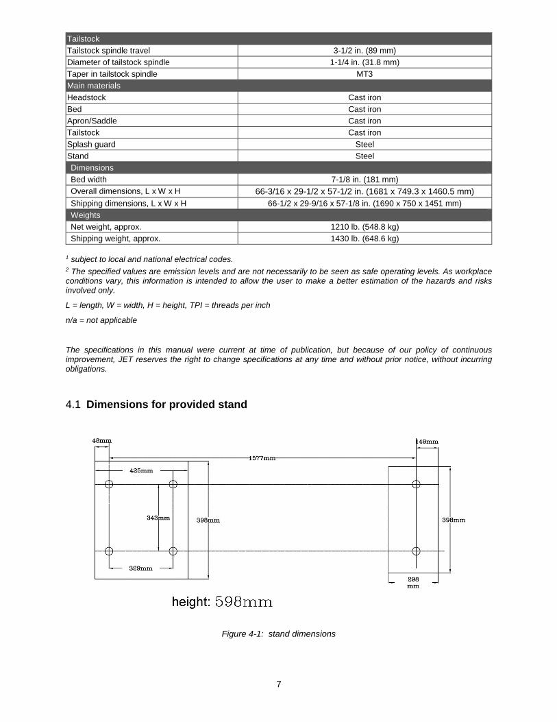
7. Compound Rest – Lubricate three ball oilers (F, Figure 6-4) once daily with Mobil DTE® Oil Heavy Medium.
8. Cross Slide – Lubricate four ball oilers (G, Figure 6-4) once daily with Mobil DTE® Oil Heavy Medium.
9. Longitudinal Feed Handwheel – Lubricate ball oiler (H, Figure 6-4) once daily with Mobil DTE® Oil Heavy Medium.
Figure 6-4
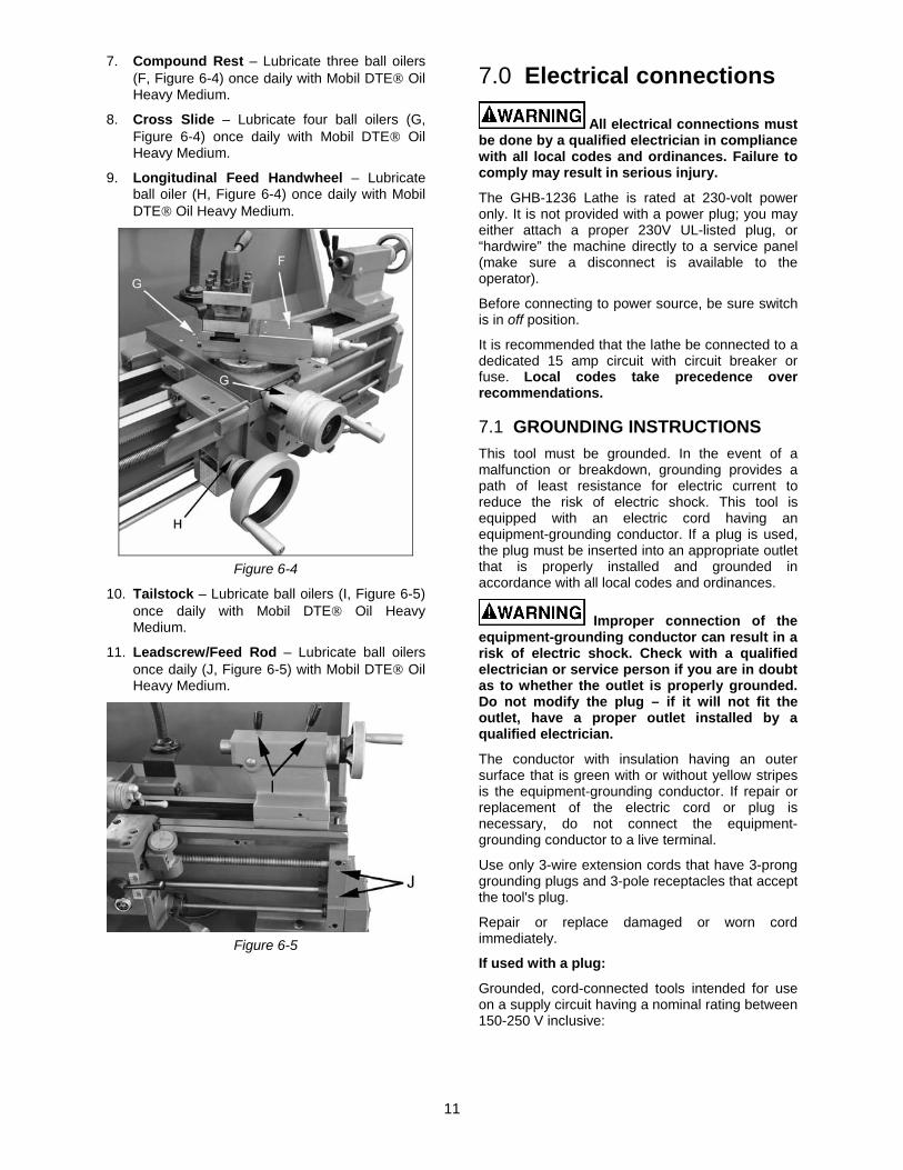
10. Tailstock – Lubricate ball oilers (I, Figure 6-5) once daily with Mobil DTE® Oil Heavy Medium.
11. Leadscrew/Feed Rod – Lubricate ball oilers once daily (J, Figure 6-5) with Mobil DTE® Oil Heavy Medium.
Figure 6-5
7.0 Electrical connections
All electrical connections must be done by a qualified electrician in compliance with all local codes and ordinances. Failure to comply may result in serious injury.
The GHB-1236 Lathe is rated at 230-volt power only. It is not provided with a power plug; you may either attach a proper 230V UL-listed plug, or “hardwire” the machine directly to a service panel (make sure a disconnect is available to the operator).
Before connecting to power source, be sure switch is in off position.
It is recommended that the lathe be connected to a dedicated 15 amp circuit with circuit breaker or fuse. Local codes take precedence over recommendations.
7.1 GROUNDING INSTRUCTIONS This tool must be grounded. In the event of a malfunction or breakdown, grounding provides a path of least resistance for electric current to reduce the risk of electric shock. This tool is equipped with an electric cord having an equipment-grounding conductor. If a plug is used, the plug must be inserted into an appropriate outlet that is properly installed and grounded in accordance with all local codes and ordinances.
Improper connection of the equipment-grounding conductor can result in a risk of electric shock. Check with a qualified electrician or service person if you are in doubt as to whether the outlet is properly grounded. Do not modify the plug – if it will not fit the outlet, have a proper outlet installed by a qualified electrician.
The conductor with insulation having an outer surface that is green with or without yellow stripes is the equipment-grounding conductor. If repair or replacement of the electric cord or plug is necessary, do not connect the equipment-grounding conductor to a live terminal.
Use only 3-wire extension cords that have 3-prong grounding plugs and 3-pole receptacles that accept the tool's plug.
Repair or replace damaged or worn cord immediately.
If used with a plug:
Grounded, cord-connected tools intended for use on a supply circuit having a nominal rating between 150-250 V inclusive:
12
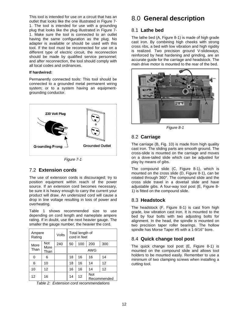
This tool is intended for use on a circuit that has an outlet that looks like the one illustrated in Figure 7-1. The tool is intended for use with a grounding plug that looks like the plug illustrated in Figure 7-1. Make sure the tool is connected to an outlet having the same configuration as the plug. No adapter is available or should be used with this tool. If the tool must be reconnected for use on a different type of electric circuit, the reconnection should be made by qualified service personnel; and after reconnection, the tool should comply with all local codes and ordinances.
If hardwired:
Permanently connected tools: This tool should be connected to a grounded metal permanent wiring system; or to a system having an equipment-grounding conductor.
Figure 7-1
7.2 Extension cords The use of extension cords is discouraged; try to position equipment within reach of the power source. If an extension cord becomes necessary, be sure it is heavy enough to carry the current your product will draw. An undersized cord will cause a drop in line voltage resulting in loss of power and overheating.
Table 1 shows recommended size to use depending on cord length and nameplate ampere rating. If in doubt, use the next heavier gauge. The smaller the gauge number, the heavier the cord.
Ampere Rating Volts Total length of
cord in feet
More Than
Not More Than
240 50 100 200 300
AWG
00 06 18 16 16 14 06 10 18 16 14 12 10 12 16 16 14 12
12 16 14 12 Not Recommended
Table 2: Extension cord recommendations
8.0 General description
8.1 Lathe bed The lathe bed (A, Figure 8-1) is made of high grade cast iron. By combining high cheeks with strong cross ribs, a bed with low vibration and high rigidity is realized. Two precision ground V-slideways, reinforced by heat hardening and grinding, are an accurate guide for the carriage and headstock. The main drive motor is mounted to the rear of the bed.
Figure 8-1
8.2 Carriage The carriage (B, Fig. 10) is made from high quality cast iron. The sliding parts are smooth ground. The cross-slide is mounted on the carriage and moves on a dove-tailed slide which can be adjusted for play by means of gibs.
The compound slide (C, Figure 8-1), which is mounted on the cross slide (D, Figure 8-1), can be rotated through 360°. The compound slide and the cross slide travel in a dovetail slide and have adjustable gibs. A four-way tool post (E, Figure 8-1) is fitted on the compound slide.
8.3 Headstock The headstock (F, Figure 8-1) is cast from high grade, low vibration cast iron. It is mounted to the bed by four bolts with two adjusting bolts for alignment. In the head, the spindle is mounted on two precision taper roller bearings. The hollow spindle has Morse Taper #5 with a 1-9/16" bore.
8.4 Quick change tool post The quick change tool post (E, Figure 8-1) is mounted on the compound slide and allows tool holders to be mounted easily. Remember to use a minimum of two clamping screws when installing a cutting tool.
13
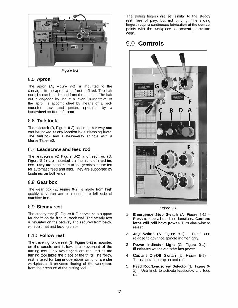
Figure 8-2
8.5 Apron The apron (A, Figure 8-2) is mounted to the carriage. In the apron a half nut is fitted. The half nut gibs can be adjusted from the outside. The half nut is engaged by use of a lever. Quick travel of the apron is accomplished by means of a bed-mounted rack and pinion, operated by a handwheel on front of apron.
8.6 Tailstock The tailstock (B, Figure 8-2) slides on a v-way and can be locked at any location by a clamping lever. The tailstock has a heavy-duty spindle with a Morse Taper #3.
8.7 Leadscrew and feed rod The leadscrew (C Figure 8-2) and feed rod (D, Figure 8-2) are mounted on the front of machine bed. They are connected to the gearbox at the left for automatic feed and lead. They are supported by bushings on both ends.
8.8 Gear box The gear box (E, Figure 8-2) is made from high quality cast iron and is mounted to left side of machine bed.
8.9 Steady rest The steady rest (F, Figure 8-2) serves as a support for shafts on the free tailstock end. The steady rest is mounted on the bedway and secured from below with bolt, nut and locking plate.
8.10 Follow rest The traveling follow rest (G, Figure 8-2) is mounted on the saddle and follows the movement of the turning tool. Only two fingers are required as the turning tool takes the place of the third. The follow rest is used for tuning operations on long, slender workpieces. It prevents flexing of the workpiece from the pressure of the cutting tool.
The sliding fingers are set similar to the steady rest, free of play, but not binding. The sliding fingers require continuous lubrication at the contact points with the workpiece to prevent premature wear.
9.0 Controls
Figure 9-1
1. Emergency Stop Switch (A, Figure 9-1) – Press to stop all machine functions. Caution: lathe will still have power. Turn clockwise to re-set.
2. Jog Switch (B, Figure 9-1) – Press and release to advance spindle momentarily.
3. Power Indicator Light (C, Figure 9-1) – Illuminates whenever lathe has power.
4. Coolant On-Off Switch (D, Figure 9-1) – Turns coolant pump on and off.
5. Feed Rod/Leadscrew Selector (E, Figure 9-1) – Use knob to activate leadscrew and feed rod.
14
6. Speed Selector Levers (F, Figure 9-1) – Use to select spindle speeds in ranges.
7. Feed Direction Selector (G, Figure 9-1) – Selects carriage travel direction when chuck is rotating in forward direction (or counter-clockwise as viewed from front of chuck).
8. Feed Rate Selector (H, Figure 9-1) – Use knobs to set desired feed, or lead rates.
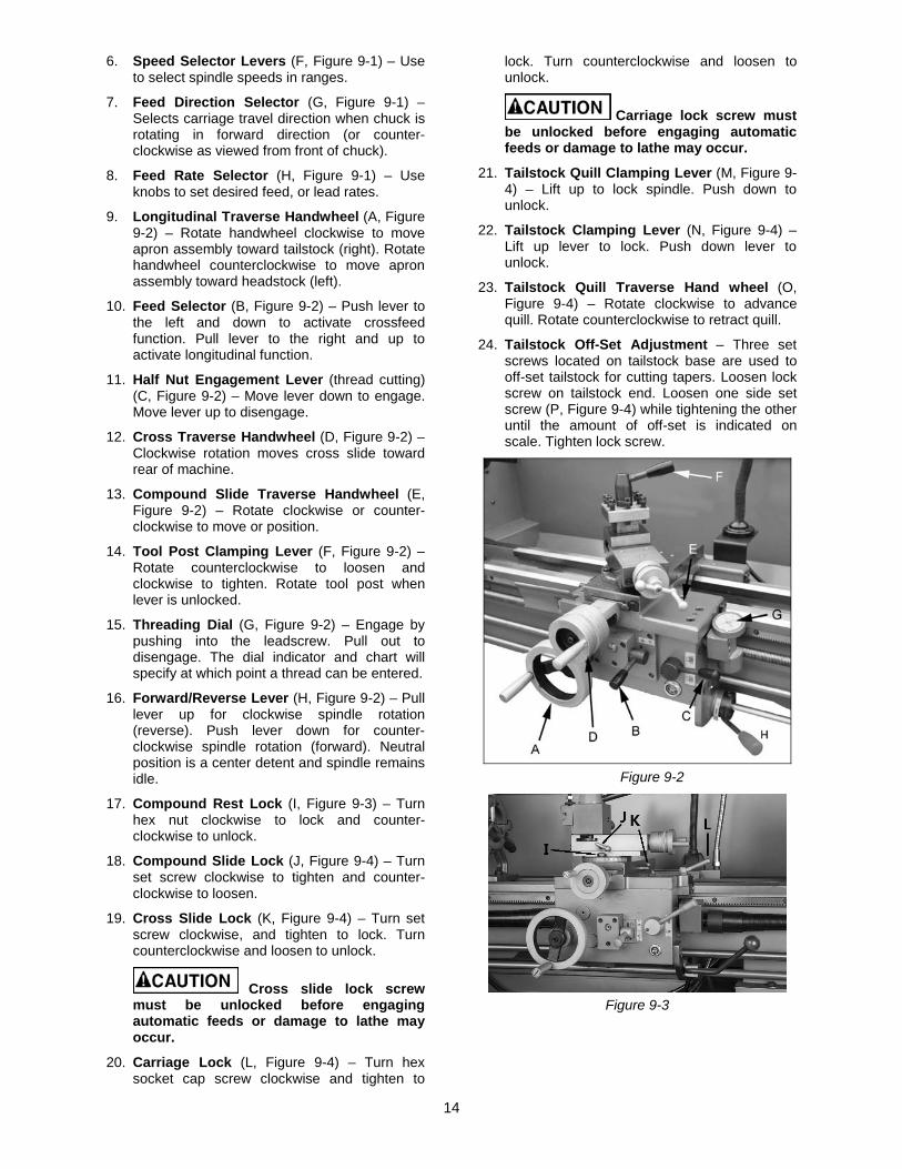
9. Longitudinal Traverse Handwheel (A, Figure 9-2) – Rotate handwheel clockwise to move apron assembly toward tailstock (right). Rotate handwheel counterclockwise to move apron assembly toward headstock (left).
10. Feed Selector (B, Figure 9-2) – Push lever to the left and down to activate crossfeed function. Pull lever to the right and up to activate longitudinal function.
11. Half Nut Engagement Lever (thread cutting) (C, Figure 9-2) – Move lever down to engage. Move lever up to disengage.
12. Cross Traverse Handwheel (D, Figure 9-2) – Clockwise rotation moves cross slide toward rear of machine.
13. Compound Slide Traverse Handwheel (E, Figure 9-2) – Rotate clockwise or counter-clockwise to move or position.
14. Tool Post Clamping Lever (F, Figure 9-2) – Rotate counterclockwise to loosen and clockwise to tighten. Rotate tool post when lever is unlocked.
15. Threading Dial (G, Figure 9-2) – Engage by pushing into the leadscrew. Pull out to disengage. The dial indicator and chart will specify at which point a thread can be entered.
16. Forward/Reverse Lever (H, Figure 9-2) – Pull lever up for clockwise spindle rotation (reverse). Push lever down for counter-clockwise spindle rotation (forward). Neutral position is a center detent and spindle remains idle.
17. Compound Rest Lock (I, Figure 9-3) – Turn hex nut clockwise to lock and counter-clockwise to unlock.
18. Compound Slide Lock (J, Figure 9-4) – Turn set screw clockwise to tighten and counter-clockwise to loosen.
19. Cross Slide Lock (K, Figure 9-4) – Turn set screw clockwise, and tighten to lock. Turn counterclockwise and loosen to unlock.
Cross slide lock screw must be unlocked before engaging automatic feeds or damage to lathe may occur.
20. Carriage Lock (L, Figure 9-4) – Turn hex socket cap screw clockwise and tighten to
lock. Turn counterclockwise and loosen to unlock.
Carriage lock screw must be unlocked before engaging automatic feeds or damage to lathe may occur.
21. Tailstock Quill Clamping Lever (M, Figure 9-4) – Lift up to lock spindle. Push down to unlock.
22. Tailstock Clamping Lever (N, Figure 9-4) – Lift up lever to lock. Push down lever to unlock.
23. Tailstock Quill Traverse Hand wheel (O, Figure 9-4) – Rotate clockwise to advance quill. Rotate counterclockwise to retract quill.
24. Tailstock Off-Set Adjustment – Three set screws located on tailstock base are used to off-set tailstock for cutting tapers. Loosen lock screw on tailstock end. Loosen one side set screw (P, Figure 9-4) while tightening the other until the amount of off-set is indicated on scale. Tighten lock screw.
Figure 9-2
Figure 9-3

15
Figure 9-4
10.0 Operation
10.1 Break-in procedure During manufacturing and testing, this lathe has been operated in the low RPM range for three hours.
To allow time for the gears and bearings to break-in and run smoothly, do not run the lathe above 755 RPM for the first six hours of operation and use.
10.2 Feed and thread selection 1. Reference the feed and thread table (A, Figure
10-1).
2. Move knobs and handle (B, Figure 10-1) to appropriate positions.
Figure 10-1
10.3 Change gear replacement Note: The 24T, 127T, and 48T gears are installed in the end gear compartment when delivered from the factory. This combination will cover most inch
feeds and threads under normal circumstances. The additional gears found in the toolbox are used for some metric threads and feeds.
1. Disconnect machine from power source.
2. Open the cover on left end of headstock.
3. Loosen hex nuts (E/F, Figure 10-2). Move quadrant out of the way.
4. Change gears (G, Figure 10-2) to match feed and thread chart.
5. Thoroughly clean and install new gears.
6. Move quadrant so the large gear meshes with the smaller gears, and tighten to secure in place. Note: Make sure there is backlash of 0.002” – 0.003” between gears. Setting gears too tight will cause excessive noise and wear.
7. Close cover and connect machine to power source.
Figure 10-2
10.4 Automatic feed operation and feed changes
1. Move the forward/reverse selector (A, Figure 10-3) up or down depending on desired direction.
Figure 10-3

16
2. Turn knob (B, Figure 10-4) counterclockwise so the arrow is pointing up to start the feed rod rotating.
Figure 10-4
10.5 Powered carriage travel Push lever (C, Figure 10-3) down to engage cross feed. Pull lever up to engage longitudinal feed.
10.6 Thread cutting 1. Set feed rate selectors (D/E/F, Figure 10-4) in
proper position for correct feed rate of the thread pitch to be cut.
2. Turn knob (B, Figure 10-4) clockwise so the arrow is pointing up to start the thread cutting.
3. Engage half nut lever (G, Figure 10-3).
4. The half nut lever and the threading dial are used to thread in the conventional manner. The thread dial chart specifies at which point a thread can be entered using the threading dial.
5. To cut metric threads, the half nuts must be left continually engaged once the start point has been selected and the half nut is initially engaged (thread dial cannot be used).
11.0 Adjustments
11.1 Saddle adjustment 1. Loosen four hex nuts (A, Figure 11-1) found on
the bottom rear of cross slide.
2. Turn each of four set screws (B, Figure 11-1) equally with a hex wrench until a slight resistance is felt. Do not overtighten.
3. Move carriage with handwheel and determine if drag is to your preference. Readjust setscrews as necessary to achieve desired drag.
4. Hold socket set screw firmly with a hex wrench and tighten hex nut to lock in place.
5. Move the carriage again and adjust if necessary. Note: Over-adjustment will cause excessive, premature wear of gibs.
Figure 11-1
11.2 Cross slide adjustment If the cross slide is too loose, follow procedure below to tighten: 1. Loosen the rear gib screw (C, Fig. 20)
approximately one turn.
2. Tighten front gib screw a quarter turn. Turn the cross slide handwheel to see if the cross slide is still loose. If it is still loose, tighten the front screw a bit more and try again.
3. When cross slide is properly adjusted, snug rear gib screw. Do not overtighten; this will cause premature wear on the gib and mating parts.
11.3 Compound slide adjustment Follow same procedure as for cross slide adjustment, to adjust the compound rest.
11.4 Tailstock adjustment If the handle will not lock the tailstock securely, use the following procedure:
1. Lower handle to unlocked position.
2. Slide tailstock to an area that will allow you to reach under the tailstock.
3. Tighten tailstock clamping nut 1/4 turn, and re-test for proper locking. Repeat as necessary.

17
11.5 Half nut gib adjustment 1. Remove thread dial assembly by unscrewing
the screw (D, Figure 11-2).
2. Loosen three hex nuts (E, Figure 11-2) found on side of apron, and turn three set screws (F, Figure 11-2) equally with a hex wrench.
3. Adjust properly for wear and play. Hold socket set screw firmly with a hex wrench and tighten hex nut to lock in place. Note: Over-adjustment will cause excessive, premature wear on gib and mating parts.
Figure 11-2
11.6 Headstock alignment The headstock has been aligned at the factory and should not require adjustment. However, if adjustment is deemed necessary, follow procedure below to align headstock.
1. Using an engineer's precision level on the bedways, make sure lathe is level side-to-side and front-to-back. If lathe is not level, correct to a level condition before proceeding. Re-test alignment if any leveling adjustments were made.
2. From steel bar stock of approximately two inches in diameter, cut a piece approximately eight inches long.
3. Place two inches of bar stock into chuck and tighten chuck. Do not use tailstock or center to support the other end.
4. Set up and cut along five inches of bar stock.
5. Using a micrometer, measure bar stock next to the chuck and at the end. The measurement should be the same.
6. If the measurements are not the same and adjustment is required, loosen the four bolts that hold headstock to bed. Do not loosen completely; some drag should remain.
7. Loosen two hex nuts found on the two adjusting bolts located on backside of headstock just above motor mount bracket. Adjust the bolts for alignment and tighten hex nuts. Tighten headstock bolts and make another cut. Keep adjusting screws after each cut until the bar stock measurements are the same. Tighten all headstock bolts and jam nuts on adjusting screws.
11.7 Removing gap bridge 1. Using an open end wrench, tighten the two
hex nuts (A, Figure 11-3). This will cause the taper pins (B, Figure 11-3) to release. Remove the taper pins.
2. Remove the four hex socket cap screws (C, Figure 11-3) with a hex key wrench.
3. Gap bridge can now be removed.
11.8 Installing gap bridge 1. Clean bottom and ends of gap bridge
thoroughly.
2. Set gap bridge in place and align.
3. Remove nuts (A, Figure 11-3) from taper pins (B, Figure 11-3).
4. Slide taper pins in their respective holes and seat using a mallet. Install nuts on taper pins finger tight.
5. Install four socket head cap screws (C, Figure 11-3) and tighten securely.
Figure 11-3
18
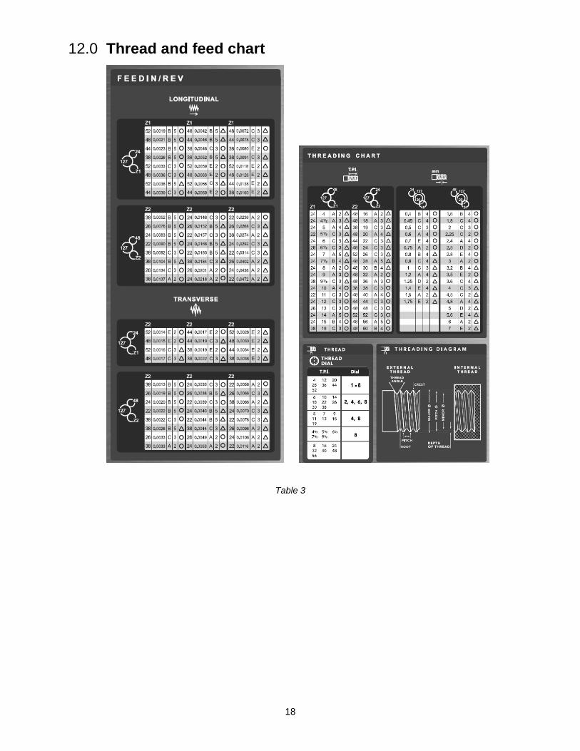
12.0 Thread and feed chart
Table 3

19
13.0 Replacement parts Replacement parts are listed on the following pages. To order parts or reach our service department, call 1-800-274-6848 Monday through Friday, 8:00 a.m. to 5:00 p.m. CST. Having the Model Number and Serial Number of your machine available when you call will allow us to serve you quickly and accurately.
Non-proprietary parts, such as fasteners, can be found at local hardware stores, or may be ordered from JET. Some parts are shown for reference only, and may not be available individually.
13.1.1 Bed Assembly – Exploded View
13.1.2 Bed Assembly – Parts List
Index No. Part No. Description Size Qty 101 ............ GHB1236-101 ........... Lathe Bed ................................................................ ...................................... 1 102 ............ TS-1492041 .............. Hex Cap Screw ........................................................ M12X40 ........................ 6 103 ............ GHB1236-103 ........... Rack Gear................................................................ ...................................... 1 104 ............ JJP8BT-123 .............. Hex Socket Hd Cap Screw ...................................... M6X15 .......................... 6 105 ............ ZX-H218 .................... Taper Pin ................................................................. 6X25MM ....................... 6 106 ............ GHB1236-106 ........... Rack......................................................................... ...................................... 2 107 ............ TS-2360121 .............. Flat Washer ............................................................. 12MM ............................ 6 108 ............ TS-1540081 .............. Hex Nut .................................................................... M12 ............................... 1 109 ............ TS-1506041 .............. Hex Socket Hd Cap Screw ...................................... M12X35 ........................ 1
20
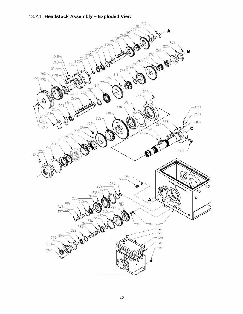
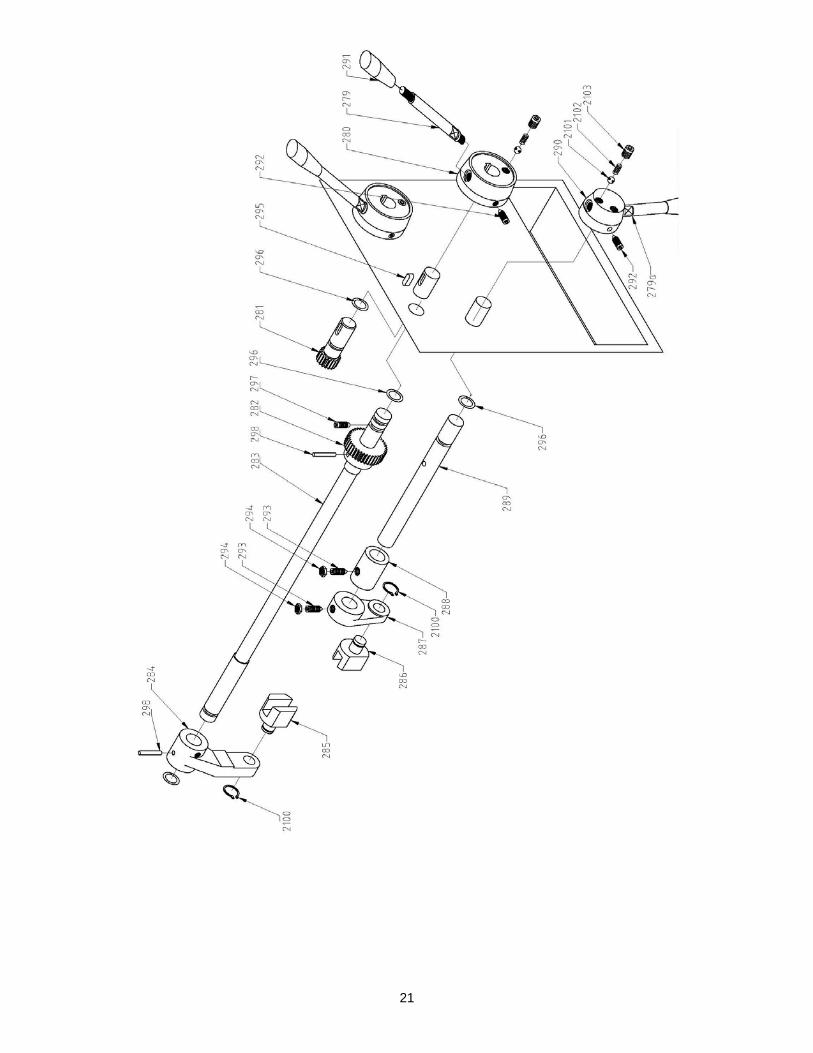
13.2.1 Headstock Assembly – Exploded View
21
22
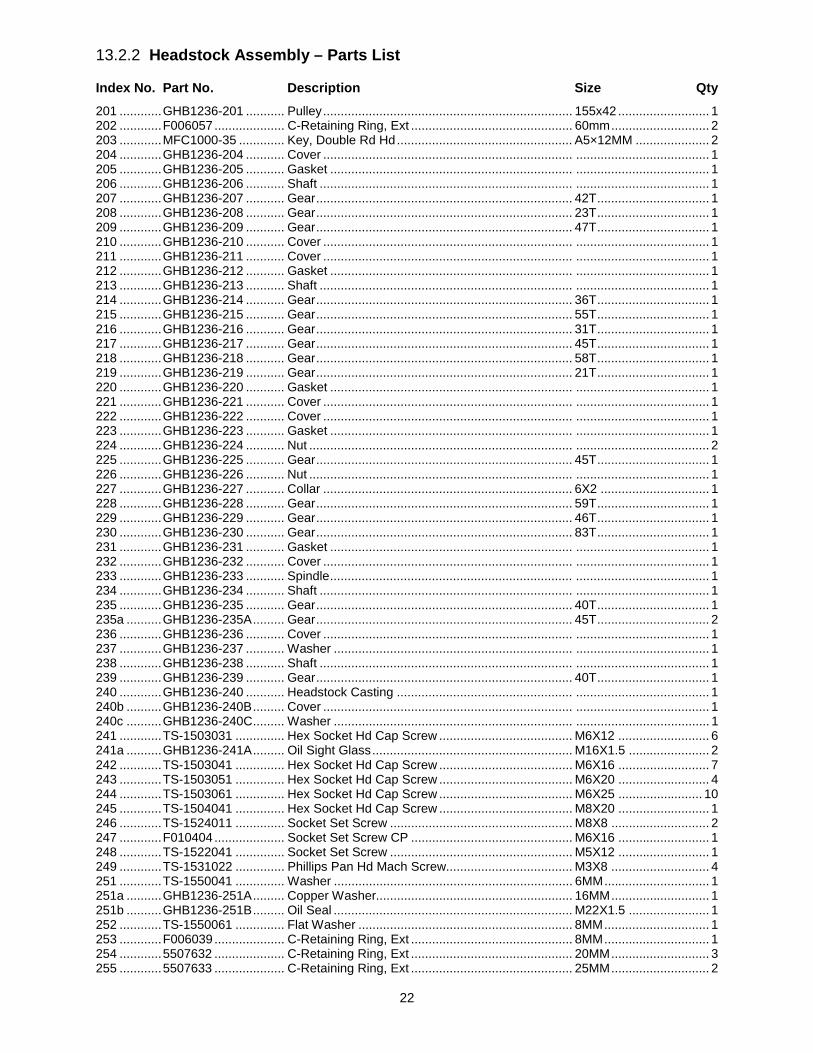
13.2.2 Headstock Assembly – Parts List
Index No. Part No. Description Size Qty 201 ............ GHB1236-201 ........... Pulley ....................................................................... 155x42 .......................... 1 202 ............ F006057 .................... C-Retaining Ring, Ext .............................................. 60mm ............................ 2 203 ............ MFC1000-35 ............. Key, Double Rd Hd .................................................. A5×12MM ..................... 2 204 ............ GHB1236-204 ........... Cover ....................................................................... ...................................... 1 205 ............ GHB1236-205 ........... Gasket ..................................................................... ...................................... 1 206 ............ GHB1236-206 ........... Shaft ........................................................................ ...................................... 1 207 ............ GHB1236-207 ........... Gear ......................................................................... 42T ................................ 1 208 ............ GHB1236-208 ........... Gear ......................................................................... 23T ................................ 1 209 ............ GHB1236-209 ........... Gear ......................................................................... 47T ................................ 1 210 ............ GHB1236-210 ........... Cover ....................................................................... ...................................... 1 211 ............ GHB1236-211 ........... Cover ....................................................................... ...................................... 1 212 ............ GHB1236-212 ........... Gasket ..................................................................... ...................................... 1 213 ............ GHB1236-213 ........... Shaft ........................................................................ ...................................... 1 214 ............ GHB1236-214 ........... Gear ......................................................................... 36T ................................ 1 215 ............ GHB1236-215 ........... Gear ......................................................................... 55T ................................ 1 216 ............ GHB1236-216 ........... Gear ......................................................................... 31T ................................ 1 217 ............ GHB1236-217 ........... Gear ......................................................................... 45T ................................ 1 218 ............ GHB1236-218 ........... Gear ......................................................................... 58T ................................ 1 219 ............ GHB1236-219 ........... Gear ......................................................................... 21T ................................ 1 220 ............ GHB1236-220 ........... Gasket ..................................................................... ...................................... 1 221 ............ GHB1236-221 ........... Cover ....................................................................... ...................................... 1 222 ............ GHB1236-222 ........... Cover ....................................................................... ...................................... 1 223 ............ GHB1236-223 ........... Gasket ..................................................................... ...................................... 1 224 ............ GHB1236-224 ........... Nut ........................................................................... ...................................... 2 225 ............ GHB1236-225 ........... Gear ......................................................................... 45T ................................ 1 226 ............ GHB1236-226 ........... Nut ........................................................................... ...................................... 1 227 ............ GHB1236-227 ........... Collar ....................................................................... 6X2 ............................... 1 228 ............ GHB1236-228 ........... Gear ......................................................................... 59T ................................ 1 229 ............ GHB1236-229 ........... Gear ......................................................................... 46T ................................ 1 230 ............ GHB1236-230 ........... Gear ......................................................................... 83T ................................ 1 231 ............ GHB1236-231 ........... Gasket ..................................................................... ...................................... 1 232 ............ GHB1236-232 ........... Cover ....................................................................... ...................................... 1 233 ............ GHB1236-233 ........... Spindle ..................................................................... ...................................... 1 234 ............ GHB1236-234 ........... Shaft ........................................................................ ...................................... 1 235 ............ GHB1236-235 ........... Gear ......................................................................... 40T ................................ 1 235a .......... GHB1236-235A ......... Gear ......................................................................... 45T ................................ 2 236 ............ GHB1236-236 ........... Cover ....................................................................... ...................................... 1 237 ............ GHB1236-237 ........... Washer .................................................................... ...................................... 1 238 ............ GHB1236-238 ........... Shaft ........................................................................ ...................................... 1 239 ............ GHB1236-239 ........... Gear ......................................................................... 40T ................................ 1 240 ............ GHB1236-240 ........... Headstock Casting .................................................. ...................................... 1 240b .......... GHB1236-240B ......... Cover ....................................................................... ...................................... 1 240c .......... GHB1236-240C ......... Washer .................................................................... ...................................... 1 241 ............ TS-1503031 .............. Hex Socket Hd Cap Screw ...................................... M6X12 .......................... 6 241a .......... GHB1236-241A ......... Oil Sight Glass ......................................................... M16X1.5 ....................... 2 242 ............ TS-1503041 .............. Hex Socket Hd Cap Screw ...................................... M6X16 .......................... 7 243 ............ TS-1503051 .............. Hex Socket Hd Cap Screw ...................................... M6X20 .......................... 4 244 ............ TS-1503061 .............. Hex Socket Hd Cap Screw ...................................... M6X25 ........................ 10 245 ............ TS-1504041 .............. Hex Socket Hd Cap Screw ...................................... M8X20 .......................... 1 246 ............ TS-1524011 .............. Socket Set Screw .................................................... M8X8 ............................ 2 247 ............ F010404 .................... Socket Set Screw CP .............................................. M6X16 .......................... 1 248 ............ TS-1522041 .............. Socket Set Screw .................................................... M5X12 .......................... 1 249 ............ TS-1531022 .............. Phillips Pan Hd Mach Screw.................................... M3X8 ............................ 4 251 ............ TS-1550041 .............. Washer .................................................................... 6MM .............................. 1 251a .......... GHB1236-251A ......... Copper Washer........................................................ 16MM ............................ 1 251b .......... GHB1236-251B ......... Oil Seal .................................................................... M22X1.5 ....................... 1 252 ............ TS-1550061 .............. Flat Washer ............................................................. 8MM .............................. 1 253 ............ F006039 .................... C-Retaining Ring, Ext .............................................. 8MM .............................. 1 254 ............ 5507632 .................... C-Retaining Ring, Ext .............................................. 20MM ............................ 3 255 ............ 5507633 .................... C-Retaining Ring, Ext .............................................. 25MM ............................ 2

23
Index No. Part No. Description Size Qty 256 ............ F006081 .................... C-Retaining Ring, Ext .............................................. 36MM ............................ 1 257 ............ F006056 .................... C-Retaining Ring, Ext .............................................. 45MM ............................ 1 258 ............ F006077 .................... C-Retaining Ring, Int ............................................... 42MM ............................ 1 259 ............ F006075 .................... C-Retaining Ring, Int ............................................... 47MM ............................ 3 260 ............ GHD20PF-379 .......... Key, Double Rd Hd .................................................. A5×28 ........................... 2 261 ............ GHB1236-261 ........... Key, Spcl.................................................................. C5×20 ........................... 1 262 ............ GHB1236-262 ........... Key, Spcl.................................................................. C5×24 ........................... 1 263 ............ HVBS710SG-307 ...... Key, Double Rd Hd .................................................. A5×80 ........................... 1 264 ............ JWL1640EVS-113 ..... Key, Double Rd Hd .................................................. A8×80 ........................... 1 265 ............ GHB1236-265 ........... Key, Double Rd Hd .................................................. A8×45 ........................... 1 266 ............ GHB1236-266 ........... Key, Double Rd Hd .................................................. A8×180 ......................... 1 267 ............ GHB1236-267 ........... Oil seal ..................................................................... 20X40X10MM ............... 1 268 ............ GHB1236-268 ........... Oil seal ..................................................................... 25X40X10MM ............... 1 269 ............ BB-6004Z .................. Bearing .................................................................... 6004-Z .......................... 1 270 ............ BB-6005Z .................. Bearing .................................................................... 6005-Z .......................... 1 271 ............ BB-6004 .................... Bearing .................................................................... 6004 .............................. 2 272 ............ BB-6204 .................... Bearing .................................................................... 6204 .............................. 1 273 ............ BB-6304 .................... Bearing .................................................................... 6304 .............................. 1 274 ............ BB-6005 .................... Bearing .................................................................... 6005 .............................. 2 275 ............ BB-30211 .................. Bearing .................................................................... 30211/P5 ...................... 1 276 ............ BB-30212 .................. Bearing .................................................................... 30212/P5 ...................... 1 277 ............ GHB1236-277 ........... Oil seal ..................................................................... 22×2.4mm ..................... 1 278 ............ GHB1236-278 ........... Pulley Brake Assembly ............................................ 25x125 .......................... 1 279 ............ GHB1236-279 ........... Handle ..................................................................... ...................................... 2 279a .......... GHB1236-279A ......... Handle ..................................................................... ...................................... 1 280 ............ GHB1236-280 ........... Boss ......................................................................... ...................................... 2 281 ............ GHB1236-281 ........... Gear ......................................................................... 19T ................................ 2 282 ............ GHB1236-282 ........... Gear ......................................................................... 38T ................................ 2 283 ............ GHB1236-283 ........... Shaft ........................................................................ ...................................... 2 284 ............ GHB1236-284 ........... Shaft Arm ................................................................. ...................................... 2 285 ............ GHB1236-285 ........... Shift Fork ................................................................. ...................................... 2 286 ............ GHB1236-286 ........... Shift Fork ................................................................. ...................................... 1 287 ............ GHB1236-287 ........... Shaft arm ................................................................. ...................................... 1 288 ............ GHB1236-288 ........... Collar. ...................................................................... ...................................... 1 289 ............ GHB1236-289 ........... Shaft ........................................................................ ...................................... 1 290 ............ GHB1236-290 ........... Boss ......................................................................... ...................................... 1 291 ............ GHB1236-291 ........... Handle Grip.............................................................. M8X40 .......................... 3 292 ............ TS-1523061 .............. Socket Set Screw CP .............................................. M6X20 .......................... 3 293 ............ TS-1524041 .............. Socket Set Screw CP .............................................. M8X16 .......................... 2 294 ............ GHB1236-294 ........... Hex Thin Nut ............................................................ M8 ................................. 2 295 ............ 50605005 .................. Key, Double Rd Hd .................................................. A5X14 ........................... 2 296 ............ GHB1236-296 ........... Oil seal ..................................................................... 16X2.4mm .................... 7 297 ............ F010438 .................... Socket Set Screw DP .............................................. M6X16 .......................... 2 298 ............ ZX-T36 ...................... Taper Pin ................................................................. 6X32 ............................. 4 2100 .......... GHD20PF-97 ............ C-Retaining Ring, Ext .............................................. 12MM ............................ 3 2101 .......... SB-6MM .................... Steel Ball.................................................................. 6MM .............................. 4 2102 .......... GHB1236-2102 ......... Spring ...................................................................... 1.2X5X14mm ................ 4 2103 .......... F010439 .................... Socket Set Screw FP ............................................... M8X8 ............................ 4 2104 .......... GHB1236-2104 ......... Shaft ........................................................................ ...................................... 1 2105 .......... CGHB1236-2105 ....... Rocker Pin ............................................................... ...................................... 1 2106 .......... TS-1504031 .............. Hex Socket Hd Cap Screw ...................................... M8X16 .......................... 3 2107 .......... GHB1236-2107 ......... Spring ...................................................................... 4.5x16x0.8mm .............. 3 2108 .......... GHB1236-2108 ......... Cam Pin ................................................................... ...................................... 3 2109 .......... GHB1236-2109 ......... Cam ........................................................................ ...................................... 3
24
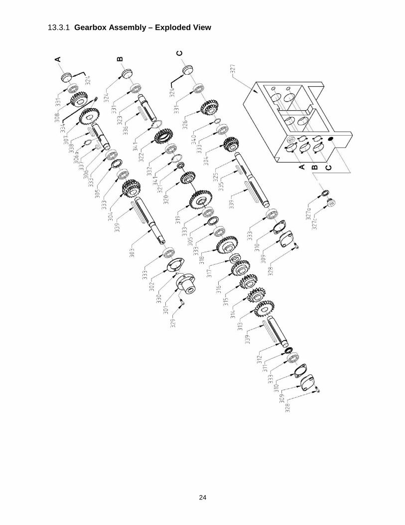
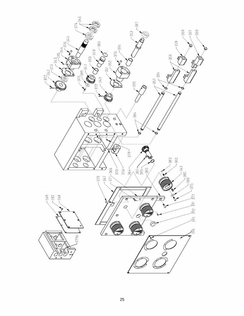
13.3.1 Gearbox Assembly – Exploded View
25

26
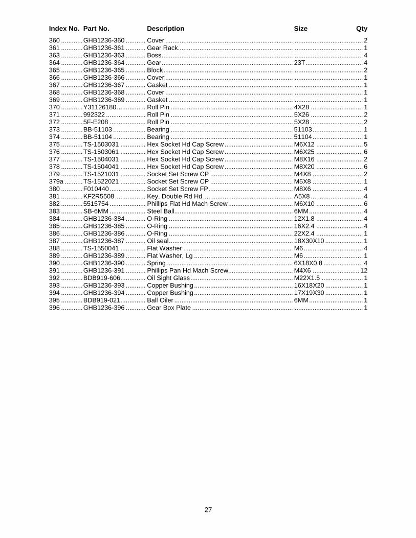
13.3.2 Gearbox Assembly – Parts List
Index No. Part No. Description Size Qty 301 ............ GHB1236-301 ........... Cover ....................................................................... ...................................... 1 302 ............ GHB1236-302 ........... Oil Seal .................................................................... ...................................... 1 303 ............ GHB1236-303 ........... Shaft ........................................................................ ...................................... 1 304 ............ GHB1236-304 ........... Compound Gear ...................................................... 18T/18T/18T ................. 2 305 ............ GHB1236-305 ........... Washer .................................................................... ...................................... 2 306 ............ GHB1236-306 ........... Shaft ........................................................................ ...................................... 1 306a .......... AB1012W-F13 ........... C-Retaining Ring, Ext .............................................. 20MM ............................ 1 307 ............ GHB1236-307 ........... Gear ......................................................................... 27T ................................ 1 308 ............ GHB1236-308 ........... Gear ......................................................................... 21T ................................ 2 309 ............ GHB1236-309 ........... Cover ....................................................................... ...................................... 2 310 ............ GHB1236-310 ........... Oil Seal .................................................................... ...................................... 2 311 ............ GHB1236-311 ........... Washer .................................................................... ...................................... 1 312 ............ GHB1236-312 ........... Shaft ........................................................................ ...................................... 1 313 ............ GHB1236-313 ........... Gear ......................................................................... 24T ................................ 1 314 ............ GHB1236-314 ........... Gear ......................................................................... 16T ................................ 1 315 ............ GHB1236-315 ........... Gear ......................................................................... 18T ................................ 1 316 ............ GHB1236-316 ........... Gear ......................................................................... 20T ................................ 1 317 ............ GHB1236-317 ........... Washer .................................................................... ...................................... 1 318 ............ GHB1236-318 ........... Gear ......................................................................... 28T ................................ 1 319 ............ GHB1236-319 ........... Compound Gear ...................................................... 30T/18T ........................ 1 320 ............ GHB1236-320 ........... Gear ......................................................................... 22T ................................ 1 321 ............ GHB1236-321 ........... Washer .................................................................... ...................................... 1 322 ............ GHB1236-322 ........... Gear ......................................................................... 23T ................................ 1 323 ............ GHB1236-323 ........... Shaft ........................................................................ ...................................... 1 324 ............ GHB1236-324 ........... Cap .......................................................................... ...................................... 3 325 ............ GHB1236-325 ........... Shaft ........................................................................ ...................................... 1 326 ............ GHB1236-326 ........... Gear ......................................................................... 22T/15T ........................ 1 327 ............ GHB1236-327 ........... Gear Box Casting .................................................... ...................................... 1 327a .......... GHB1236-327A ......... Copper Washer........................................................ 16mm ............................ 2 327c .......... GHB1236-327C ......... Oil Plug .................................................................... M16X1.5 ....................... 2 328 ............ TS-1503031 .............. Hex Socket Hd Cap Screw ...................................... M6X12 .......................... 4 329 ............ TS-1503041 .............. Hex Socket Hd Cap Screw ...................................... M6X16 .......................... 3 330 ............ BDB919-021 .............. Oil Port ..................................................................... 6MM .............................. 1 331 ............ BB-6002 .................... Bearing .................................................................... 6002 .............................. 3 332 ............ BB-16003 .................. Bearing .................................................................... 16003 ............................ 1 333 ............ BB-6003 .................... Bearing .................................................................... 6003 .............................. 8 334 ............ TS-2276081 .............. Socket Set Screw .................................................... M6X8 ............................ 1 335 ............ EGH1740-B62 ........... Key, Double Rd Hd .................................................. A5×35 ........................... 1 336 ............ 5303911 .................... Key........................................................................... C5X40 ........................... 1 337 ............ EGH1880-G19 .......... Key, Double Rd Hd .................................................. A6×15 ........................... 1 338 ............ JWBS14SF-216 ........ Key, Double Rd Hd .................................................. A6×35 ........................... 1 339 ............ E1340VS-A119 ......... Key, Double Rd Hd .................................................. A6×90 ........................... 3 340 ............ HVBS7M-219B .......... C-Retaining Ring, Ext .............................................. 17MM ............................ 1 341 ............ EBL1236VS-G81 ....... C-Retaining Ring, Int ............................................... 35MM ............................ 2 342 ............ GHB1236-342 ........... Gear ......................................................................... 21T ................................ 1 343 ............ GHB1236-343 ........... Oil seal ..................................................................... ...................................... 1 344 ............ GHB1236-344 ........... Cover ....................................................................... ...................................... 1 345 ............ GHB1236-345 ........... Shaft ........................................................................ ...................................... 1 346 ............ GHB1236-346 ........... Nut ........................................................................... ...................................... 2 347 ............ GHB1236-347 ........... Gear ......................................................................... 17T ................................ 1 348 ............ GHB1236-348 ........... Shaft ........................................................................ ...................................... 1 349 ............ GHB1236-349 ........... Gear ......................................................................... 15T ................................ 1 351 ............ GHB1236-351 ........... Oil Seal .................................................................... ...................................... 1 352 ............ GHB1236-352 ........... Cover ....................................................................... ...................................... 1 353 ............ GHB1236-353 ........... Shaft ........................................................................ ...................................... 1 355 ............ GHB1236-355 ........... Shaft ........................................................................ ...................................... 1 356 ............ GHB1236-356 ........... Position Piece .......................................................... ...................................... 1 357 ............ GHB1236-357 ........... Shaft ........................................................................ ...................................... 2 358 ............ GHB1236-358 ........... Gear Rack................................................................ ...................................... 2 359 ............ GHB1236-359 ........... Gear Rack................................................................ ...................................... 1
27
Index No. Part No. Description Size Qty 360 ............ GHB1236-360 ........... Cover ....................................................................... ...................................... 2 361 ............ GHB1236-361 ........... Gear Rack................................................................ ...................................... 1 363 ............ GHB1236-363 ........... Boss ......................................................................... ...................................... 4 364 ............ GHB1236-364 ........... Gear ......................................................................... 23T ................................ 4 365 ............ GHB1236-365 ........... Block ........................................................................ ...................................... 2 366 ............ GHB1236-366 ........... Cover ....................................................................... ...................................... 1 367 ............ GHB1236-367 ........... Gasket ..................................................................... ...................................... 1 368 ............ GHB1236-368 ........... Cover ....................................................................... ...................................... 1 369 ............ GHB1236-369 ........... Gasket ..................................................................... ...................................... 1 370 ............ Y31126180 ................ Roll Pin .................................................................... 4X28 ............................. 1 371 ............ 992322 ...................... Roll Pin .................................................................... 5X26 ............................. 2 372 ............ 5F-E208 .................... Roll Pin .................................................................... 5X28 ............................. 2 373 ............ BB-51103 .................. Bearing .................................................................... 51103 ............................ 1 374 ............ BB-51104 .................. Bearing .................................................................... 51104 ............................ 1 375 ............ TS-1503031 .............. Hex Socket Hd Cap Screw ...................................... M6X12 .......................... 5 376 ............ TS-1503061 .............. Hex Socket Hd Cap Screw ...................................... M6X25 .......................... 6 377 ............ TS-1504031 .............. Hex Socket Hd Cap Screw ...................................... M8X16 .......................... 2 378 ............ TS-1504041 .............. Hex Socket Hd Cap Screw ...................................... M8X20 .......................... 6 379 ............ TS-1521031 .............. Socket Set Screw CP .............................................. M4X8 ............................ 2 379a .......... TS-1522021 .............. Socket Set Screw CP .............................................. M5X8 ............................ 1 380 ............ F010440 .................... Socket Set Screw FP ............................................... M8X6 ............................ 4 381 ............ KF2R5508 ................. Key, Double Rd Hd .................................................. A5X8 ............................. 4 382 ............ 5515754 .................... Phillips Flat Hd Mach Screw .................................... M6X10 .......................... 6 383 ............ SB-6MM .................... Steel Ball.................................................................. 6MM .............................. 4 384 ............ GHB1236-384 ........... O-Ring ..................................................................... 12X1.8 .......................... 4 385 ............ GHB1236-385 ........... O-Ring ..................................................................... 16X2.4 .......................... 4 386 ............ GHB1236-386 ........... O-Ring ..................................................................... 22X2.4 .......................... 1 387 ............ GHB1236-387 ........... Oil seal ..................................................................... 18X30X10 ..................... 1 388 ............ TS-1550041 .............. Flat Washer ............................................................. M6 ................................. 4 389 ............ GHB1236-389 ........... Flat Washer, Lg ....................................................... M6 ................................. 1 390 ............ GHB1236-390 ........... Spring ...................................................................... 6X18X0.8 ...................... 4 391 ............ GHB1236-391 ........... Phillips Pan Hd Mach Screw.................................... M4X6 .......................... 12 392 ............ BDB919-606 .............. Oil Sight Glass ......................................................... M22X1.5 ....................... 1 393 ............ GHB1236-393 ........... Copper Bushing ....................................................... 16X18X20 ..................... 1 394 ............ GHB1236-394 ........... Copper Bushing ....................................................... 17X19X30 ..................... 1 395 ............ BDB919-021 .............. Ball Oiler .................................................................. 6MM .............................. 1 396 ............ GHB1236-396 ........... Gear Box Plate ........................................................ ...................................... 1

28
13.4.1 Apron Assembly – Exploded View
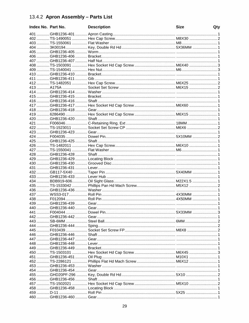
29
13.4.2 Apron Assembly – Parts List
Index No. Part No. Description Size Qty 401 ............ GHB1236-401 ........... Apron Casting .......................................................... ...................................... 1 402 ............ TS-1490051 .............. Hex Cap Screw ........................................................ M8X30 .......................... 2 403 ............ TS-1550061 .............. Flat Washer ............................................................. M8 ................................. 1 404 ............ 3K00194 .................... Key, Double Rd Hd .................................................. 5X36MM ....................... 1 405 ............ GHB1236-405 ........... Worm ....................................................................... ...................................... 1 406 ............ GHB1236-406 ........... Bracket..................................................................... ...................................... 1 407 ............ GHB1236-407 ........... Half Nut .................................................................... ...................................... 1 408 ............ TS-1503091 .............. Hex Socket Hd Cap Screw ...................................... M6X40 .......................... 3 409 ............ TS-1540041 .............. Hex Nut .................................................................... M6 ................................. 3 410 ............ GHB1236-410 ........... Bracket..................................................................... ...................................... 1 411 ............ GHB1236-411 ........... Gib ........................................................................... ...................................... 1 412 ............ TS-1482051 .............. Hex Cap Screw ........................................................ M6X25 .......................... 2 413 ............ A175A ....................... Socket Set Screw .................................................... M6X15 .......................... 2 414 ............ GHB1236-414 ........... Washer .................................................................... ...................................... 1 415 ............ GHB1236-415 ........... Bracket..................................................................... ...................................... 1 416 ............ GHB1236-416 ........... Shaft ........................................................................ ...................................... 1 417 ............ GHB1236-417 ........... Hex Socket Hd Cap Screw ...................................... M6X60 .......................... 1 418 ............ GHB1236-418 ........... Gear ......................................................................... ...................................... 1 419 ............ 6286490 .................... Hex Socket Hd Cap Screw ...................................... M6X15 .......................... 1 420 ............ GHB1236-420 ........... Shaft ........................................................................ ...................................... 1 421 ............ F006046 .................... C-Retaining Ring, Ext .............................................. 18MM ............................ 1 422 ............ TS-1523011 .............. Socket Set Screw CP .............................................. M6X6 ............................ 2 423 ............ GHB1236-423 ........... Gear ......................................................................... ...................................... 1 424 ............ F004035 .................... Dowel Pin................................................................. 5X10MM ....................... 2 425 ............ GHB1236-425 ........... Shaft ........................................................................ ...................................... 1 426 ............ TS-1482011 .............. Hex Cap Screw ........................................................ M6X10 .......................... 1 427 ............ TS-1550041 .............. Flat Washer ............................................................. M6 ................................. 1 428 ............ GHB1236-428 ........... Shaft ........................................................................ ...................................... 1 429 ............ GHB1236-429 ........... Locating Block ......................................................... ...................................... 1 430 ............ GHB1236-430 ........... Grooved Disc ........................................................... ...................................... 1 431 ............ GHB1236-431 ........... Lever ........................................................................ ...................................... 1 432 ............ GB117-5X40 ............. Taper Pin ................................................................. 5X40MM ....................... 1 433 ............ GHB1236-433 ........... Lever Hub ................................................................ ...................................... 1 434 ............ BDB919-606 .............. Oil Sight Glass ......................................................... M22X1.5 ....................... 1 435 ............ TS-1533042 .............. Phillips Pan Hd Mach Screw.................................... M5X12 .......................... 2 436 ............ GHB1236-436 ........... Washer .................................................................... ...................................... 1 437 ............ WSS3-017 ................. Roll Pin .................................................................... 4X30MM ....................... 1 438 ............ F012094 .................... Roll Pin .................................................................... 4X50MM ....................... 1 439 ............ GHB1236-439 ........... Gear ......................................................................... ...................................... 1 440 ............ GHB1236-440 ........... Gear ......................................................................... ...................................... 1 441 ............ F004044 .................... Dowel Pin................................................................. 5X33MM ....................... 3 442 ............ GHB1236-442 ........... Gear ......................................................................... ...................................... 1 443 ............ SB-6MM .................... Steel Ball.................................................................. 6MM .............................. 2 444 ............ GHB1236-444 ........... Sping........................................................................ ...................................... 2 445 ............ F010439 .................... Socket Set Screw FP ............................................... M8X8 ............................ 2 446 ............ GHB1236-446 ........... Shaft ........................................................................ ...................................... 1 447 ............ GHB1236-447 ........... Gear ......................................................................... ...................................... 1 448 ............ GHB1236-448 ........... Lever ........................................................................ ...................................... 1 449 ............ GHB1236-449 ........... Bracket..................................................................... ...................................... 1 450 ............ TS-1503101 .............. Hex Socket Hd Cap Screw ...................................... M6X45 .......................... 3 451 ............ GHB1236-451 ........... Oil Plug .................................................................... M10X1 .......................... 1 452 ............ TS-2286121 .............. Phillips Flat Hd Mach Screw .................................... M6X12 .......................... 1 453 ............ GHB1236-453 ........... Washer .................................................................... ...................................... 1 454 ............ GHB1236-454 ........... Gear ......................................................................... ...................................... 1 455 ............ GHD20PF-296 .......... Key, Double Rd Hd .................................................. 5X10 ............................. 2 456 ............ GHB1236-456 ........... Shaft ........................................................................ ...................................... 1 457 ............ TS-1502021 .............. Hex Socket Hd Cap Screw ...................................... M5X10 .......................... 2 458 ............ GHB1236-458 ........... Locating Block ......................................................... ...................................... 1 459 ............ D-11 .......................... Roll Pin .................................................................... 5X25 ............................. 1 460 ............ GHB1236-460 ........... Gear ......................................................................... ...................................... 1
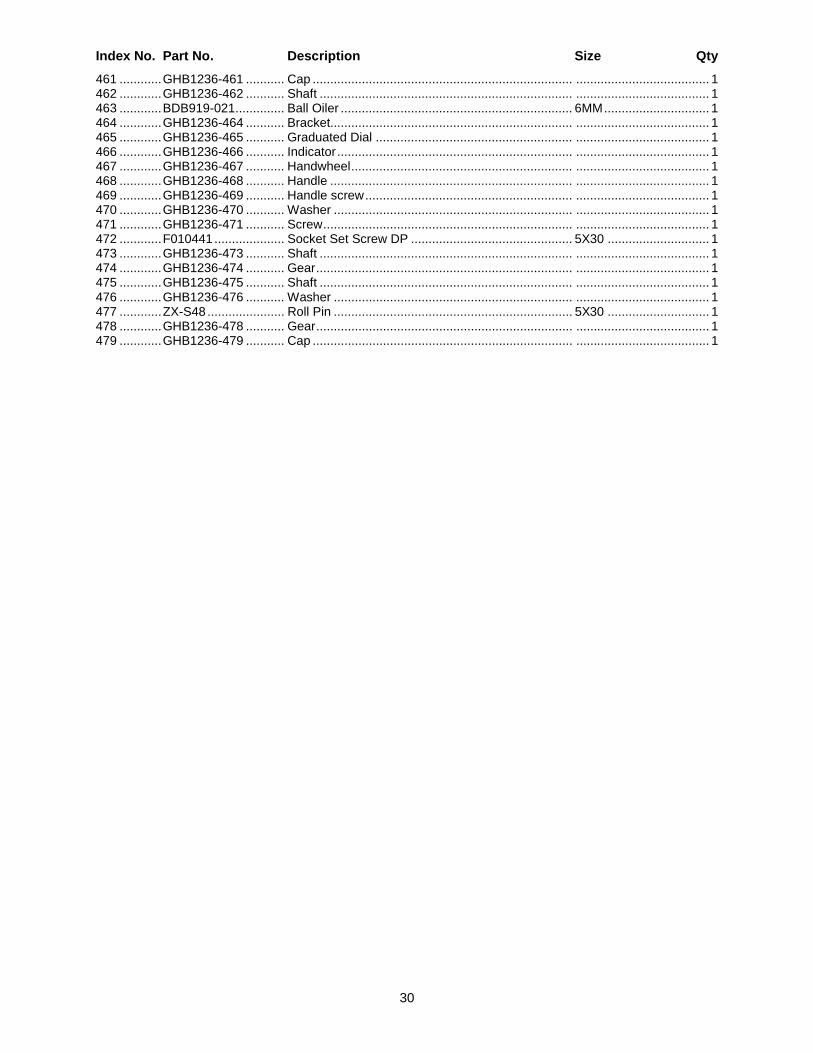
30
Index No. Part No. Description Size Qty 461 ............ GHB1236-461 ........... Cap .......................................................................... ...................................... 1 462 ............ GHB1236-462 ........... Shaft ........................................................................ ...................................... 1 463 ............ BDB919-021 .............. Ball Oiler .................................................................. 6MM .............................. 1 464 ............ GHB1236-464 ........... Bracket..................................................................... ...................................... 1 465 ............ GHB1236-465 ........... Graduated Dial ........................................................ ...................................... 1 466 ............ GHB1236-466 ........... Indicator ................................................................... ...................................... 1 467 ............ GHB1236-467 ........... Handwheel ............................................................... ...................................... 1 468 ............ GHB1236-468 ........... Handle ..................................................................... ...................................... 1 469 ............ GHB1236-469 ........... Handle screw ........................................................... ...................................... 1 470 ............ GHB1236-470 ........... Washer .................................................................... ...................................... 1 471 ............ GHB1236-471 ........... Screw ....................................................................... ...................................... 1 472 ............ F010441 .................... Socket Set Screw DP .............................................. 5X30 ............................. 1 473 ............ GHB1236-473 ........... Shaft ........................................................................ ...................................... 1 474 ............ GHB1236-474 ........... Gear ......................................................................... ...................................... 1 475 ............ GHB1236-475 ........... Shaft ........................................................................ ...................................... 1 476 ............ GHB1236-476 ........... Washer .................................................................... ...................................... 1 477 ............ ZX-S48 ...................... Roll Pin .................................................................... 5X30 ............................. 1 478 ............ GHB1236-478 ........... Gear ......................................................................... ...................................... 1 479 ............ GHB1236-479 ........... Cap .......................................................................... ...................................... 1
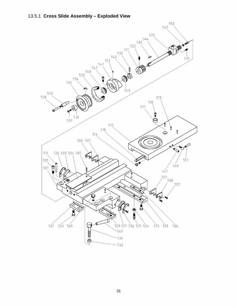
31
13.5.1 Cross Slide Assembly – Exploded View
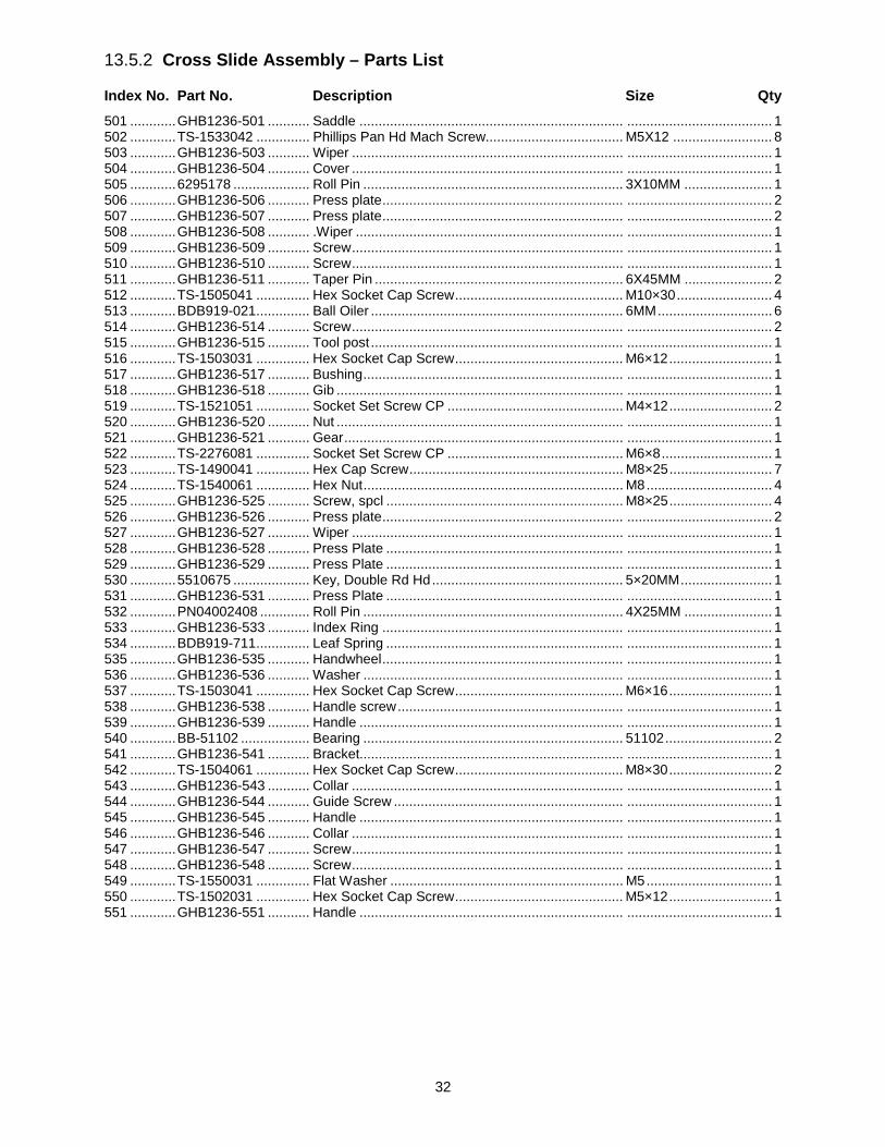
32
13.5.2 Cross Slide Assembly – Parts List
Index No. Part No. Description Size Qty 501 ............ GHB1236-501 ........... Saddle ..................................................................... ...................................... 1 502 ............ TS-1533042 .............. Phillips Pan Hd Mach Screw.................................... M5X12 .......................... 8 503 ............ GHB1236-503 ........... Wiper ....................................................................... ...................................... 1 504 ............ GHB1236-504 ........... Cover ....................................................................... ...................................... 1 505 ............ 6295178 .................... Roll Pin .................................................................... 3X10MM ....................... 1 506 ............ GHB1236-506 ........... Press plate ............................................................... ...................................... 2 507 ............ GHB1236-507 ........... Press plate ............................................................... ...................................... 2 508 ............ GHB1236-508 ........... .Wiper ...................................................................... ...................................... 1 509 ............ GHB1236-509 ........... Screw ....................................................................... ...................................... 1 510 ............ GHB1236-510 ........... Screw ....................................................................... ...................................... 1 511 ............ GHB1236-511 ........... Taper Pin ................................................................. 6X45MM ....................... 2 512 ............ TS-1505041 .............. Hex Socket Cap Screw ............................................ M10×30 ......................... 4 513 ............ BDB919-021 .............. Ball Oiler .................................................................. 6MM .............................. 6 514 ............ GHB1236-514 ........... Screw ....................................................................... ...................................... 2 515 ............ GHB1236-515 ........... Tool post .................................................................. ...................................... 1 516 ............ TS-1503031 .............. Hex Socket Cap Screw ............................................ M6×12 ........................... 1 517 ............ GHB1236-517 ........... Bushing .................................................................... ...................................... 1 518 ............ GHB1236-518 ........... Gib ........................................................................... ...................................... 1 519 ............ TS-1521051 .............. Socket Set Screw CP .............................................. M4×12 ........................... 2 520 ............ GHB1236-520 ........... Nut ........................................................................... ...................................... 1 521 ............ GHB1236-521 ........... Gear ......................................................................... ...................................... 1 522 ............ TS-2276081 .............. Socket Set Screw CP .............................................. M6×8 ............................. 1 523 ............ TS-1490041 .............. Hex Cap Screw ........................................................ M8×25 ........................... 7 524 ............ TS-1540061 .............. Hex Nut .................................................................... M8 ................................. 4 525 ............ GHB1236-525 ........... Screw, spcl .............................................................. M8×25 ........................... 4 526 ............ GHB1236-526 ........... Press plate ............................................................... ...................................... 2 527 ............ GHB1236-527 ........... Wiper ....................................................................... ...................................... 1 528 ............ GHB1236-528 ........... Press Plate .............................................................. ...................................... 1 529 ............ GHB1236-529 ........... Press Plate .............................................................. ...................................... 1 530 ............ 5510675 .................... Key, Double Rd Hd .................................................. 5×20MM ........................ 1 531 ............ GHB1236-531 ........... Press Plate .............................................................. ...................................... 1 532 ............ PN04002408 ............. Roll Pin .................................................................... 4X25MM ....................... 1 533 ............ GHB1236-533 ........... Index Ring ............................................................... ...................................... 1 534 ............ BDB919-711 .............. Leaf Spring .............................................................. ...................................... 1 535 ............ GHB1236-535 ........... Handwheel ............................................................... ...................................... 1 536 ............ GHB1236-536 ........... Washer .................................................................... ...................................... 1 537 ............ TS-1503041 .............. Hex Socket Cap Screw ............................................ M6×16 ........................... 1 538 ............ GHB1236-538 ........... Handle screw ........................................................... ...................................... 1 539 ............ GHB1236-539 ........... Handle ..................................................................... ...................................... 1 540 ............ BB-51102 .................. Bearing .................................................................... 51102 ............................ 2 541 ............ GHB1236-541 ........... Bracket..................................................................... ...................................... 1 542 ............ TS-1504061 .............. Hex Socket Cap Screw ............................................ M8×30 ........................... 2 543 ............ GHB1236-543 ........... Collar ....................................................................... ...................................... 1 544 ............ GHB1236-544 ........... Guide Screw ............................................................ ...................................... 1 545 ............ GHB1236-545 ........... Handle ..................................................................... ...................................... 1 546 ............ GHB1236-546 ........... Collar ....................................................................... ...................................... 1 547 ............ GHB1236-547 ........... Screw ....................................................................... ...................................... 1 548 ............ GHB1236-548 ........... Screw ....................................................................... ...................................... 1 549 ............ TS-1550031 .............. Flat Washer ............................................................. M5 ................................. 1 550 ............ TS-1502031 .............. Hex Socket Cap Screw ............................................ M5×12 ........................... 1 551 ............ GHB1236-551 ........... Handle ..................................................................... ...................................... 1
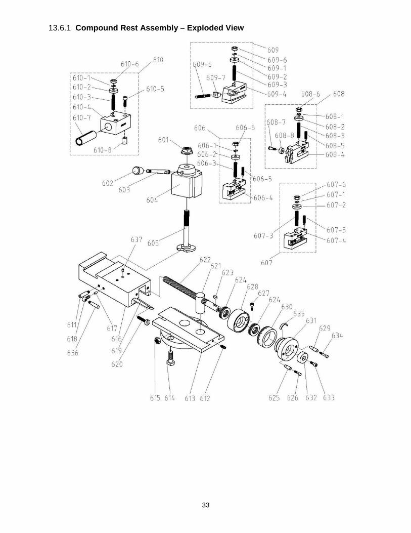
33
13.6.1 Compound Rest Assembly – Exploded View
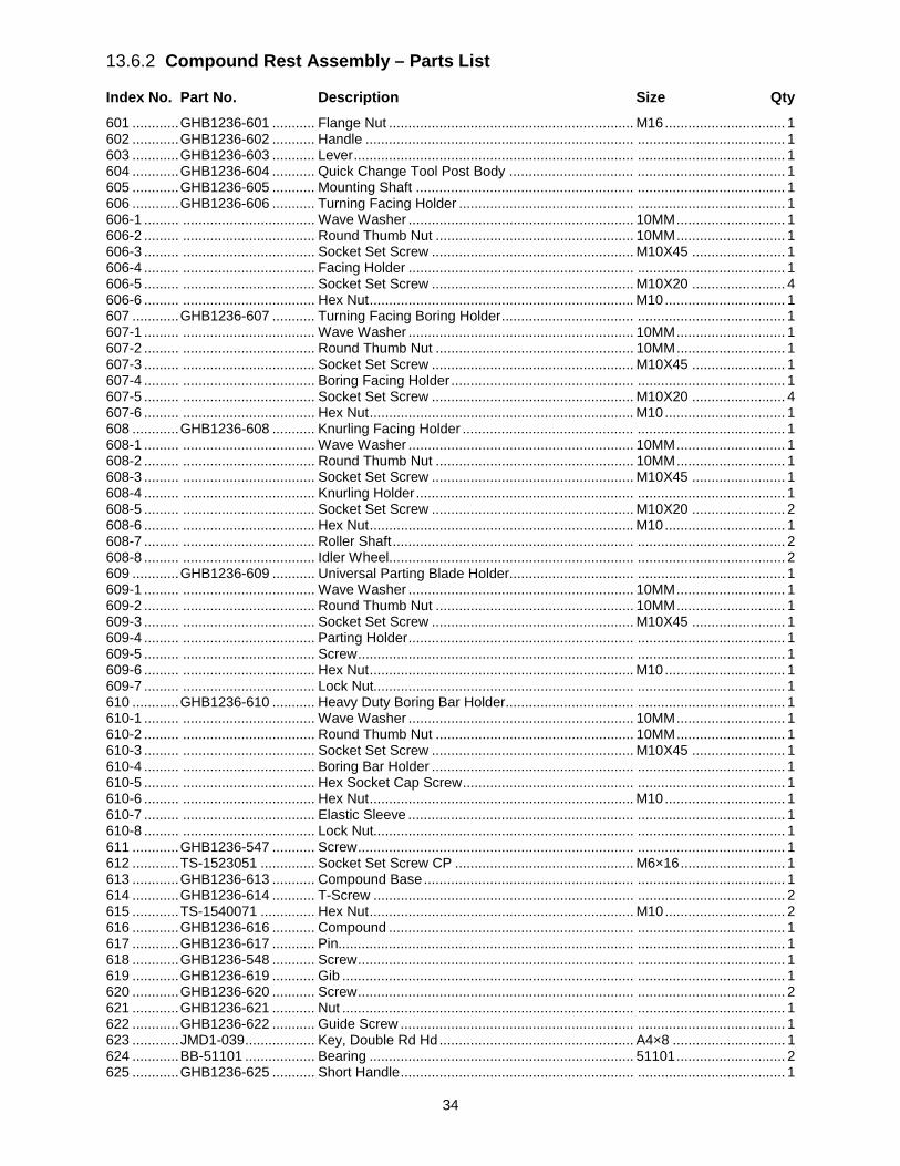
34
13.6.2 Compound Rest Assembly – Parts List
Index No. Part No. Description Size Qty 601 ............ GHB1236-601 ........... Flange Nut ............................................................... M16 ............................... 1 602 ............ GHB1236-602 ........... Handle ..................................................................... ...................................... 1 603 ............ GHB1236-603 ........... Lever ........................................................................ ...................................... 1 604 ............ GHB1236-604 ........... Quick Change Tool Post Body ................................ ...................................... 1 605 ............ GHB1236-605 ........... Mounting Shaft ........................................................ ...................................... 1 606 ............ GHB1236-606 ........... Turning Facing Holder ............................................. ...................................... 1 606-1 ......... .................................. Wave Washer .......................................................... 10MM ............................ 1 606-2 ......... .................................. Round Thumb Nut ................................................... 10MM ............................ 1 606-3 ......... .................................. Socket Set Screw .................................................... M10X45 ........................ 1 606-4 ......... .................................. Facing Holder .......................................................... ...................................... 1 606-5 ......... .................................. Socket Set Screw .................................................... M10X20 ........................ 4 606-6 ......... .................................. Hex Nut .................................................................... M10 ............................... 1 607 ............ GHB1236-607 ........... Turning Facing Boring Holder .................................. ...................................... 1 607-1 ......... .................................. Wave Washer .......................................................... 10MM ............................ 1 607-2 ......... .................................. Round Thumb Nut ................................................... 10MM ............................ 1 607-3 ......... .................................. Socket Set Screw .................................................... M10X45 ........................ 1 607-4 ......... .................................. Boring Facing Holder ............................................... ...................................... 1 607-5 ......... .................................. Socket Set Screw .................................................... M10X20 ........................ 4 607-6 ......... .................................. Hex Nut .................................................................... M10 ............................... 1 608 ............ GHB1236-608 ........... Knurling Facing Holder ............................................ ...................................... 1 608-1 ......... .................................. Wave Washer .......................................................... 10MM ............................ 1 608-2 ......... .................................. Round Thumb Nut ................................................... 10MM ............................ 1 608-3 ......... .................................. Socket Set Screw .................................................... M10X45 ........................ 1 608-4 ......... .................................. Knurling Holder ........................................................ ...................................... 1 608-5 ......... .................................. Socket Set Screw .................................................... M10X20 ........................ 2 608-6 ......... .................................. Hex Nut .................................................................... M10 ............................... 1 608-7 ......... .................................. Roller Shaft .............................................................. ...................................... 2 608-8 ......... .................................. Idler Wheel............................................................... ...................................... 2 609 ............ GHB1236-609 ........... Universal Parting Blade Holder................................ ...................................... 1 609-1 ......... .................................. Wave Washer .......................................................... 10MM ............................ 1 609-2 ......... .................................. Round Thumb Nut ................................................... 10MM ............................ 1 609-3 ......... .................................. Socket Set Screw .................................................... M10X45 ........................ 1 609-4 ......... .................................. Parting Holder .......................................................... ...................................... 1 609-5 ......... .................................. Screw ....................................................................... ...................................... 1 609-6 ......... .................................. Hex Nut .................................................................... M10 ............................... 1 609-7 ......... .................................. Lock Nut................................................................... ...................................... 1 610 ............ GHB1236-610 ........... Heavy Duty Boring Bar Holder................................. ...................................... 1 610-1 ......... .................................. Wave Washer .......................................................... 10MM ............................ 1 610-2 ......... .................................. Round Thumb Nut ................................................... 10MM ............................ 1 610-3 ......... .................................. Socket Set Screw .................................................... M10X45 ........................ 1 610-4 ......... .................................. Boring Bar Holder .................................................... ...................................... 1 610-5 ......... .................................. Hex Socket Cap Screw ............................................ ...................................... 1 610-6 ......... .................................. Hex Nut .................................................................... M10 ............................... 1 610-7 ......... .................................. Elastic Sleeve .......................................................... ...................................... 1 610-8 ......... .................................. Lock Nut................................................................... ...................................... 1 611 ............ GHB1236-547 ........... Screw ....................................................................... ...................................... 1 612 ............ TS-1523051 .............. Socket Set Screw CP .............................................. M6×16 ........................... 1 613 ............ GHB1236-613 ........... Compound Base ...................................................... ...................................... 1 614 ............ GHB1236-614 ........... T-Screw ................................................................... ...................................... 2 615 ............ TS-1540071 .............. Hex Nut .................................................................... M10 ............................... 2 616 ............ GHB1236-616 ........... Compound ............................................................... ...................................... 1 617 ............ GHB1236-617 ........... Pin............................................................................ ...................................... 1 618 ............ GHB1236-548 ........... Screw ....................................................................... ...................................... 1 619 ............ GHB1236-619 ........... Gib ........................................................................... ...................................... 1 620 ............ GHB1236-620 ........... Screw ....................................................................... ...................................... 2 621 ............ GHB1236-621 ........... Nut ........................................................................... ...................................... 1 622 ............ GHB1236-622 ........... Guide Screw ............................................................ ...................................... 1 623 ............ JMD1-039 .................. Key, Double Rd Hd .................................................. A4×8 ............................. 1 624 ............ BB-51101 .................. Bearing .................................................................... 51101 ............................ 2 625 ............ GHB1236-625 ........... Short Handle ............................................................ ...................................... 1

35
626 ............ GHB1236-626 ........... Bolt........................................................................... ...................................... 1 627 ............ GHB1236-627 ........... Hex Socket Hd Cap Screw ...................................... M6×25 ........................... 2 628 ............ GHB1236-628 ........... Bearing Housing ...................................................... ...................................... 1 629 ............ GHB1236-629 ........... Long Handle ............................................................ ...................................... 1 630 ............ GHB1236-630 ........... Index Ring ............................................................... ...................................... 1 631 ............ GHB1236-631 ........... Handwheel ............................................................... ...................................... 1 632 ............ GHB1236-632 ........... Washer .................................................................... ...................................... 1 633 ............ GHB1236-633 ........... Hex Socket Cap Screw ............................................ M6×12 ........................... 1 634 ............ GHB1236-634 ........... Bolt........................................................................... ...................................... 1 635 ............ GHB1236-635 ........... Leaf spring ............................................................... ...................................... 1 636 ............ GHB1236-551 ........... Handle ..................................................................... ...................................... 1 637 ............ BDB919-021 .............. Ball Oiler .................................................................. 6MM .............................. 3
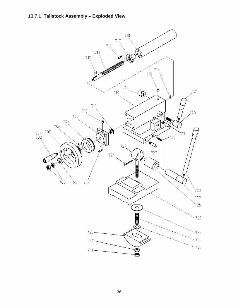
36
13.7.1 Tailstock Assembly – Exploded View
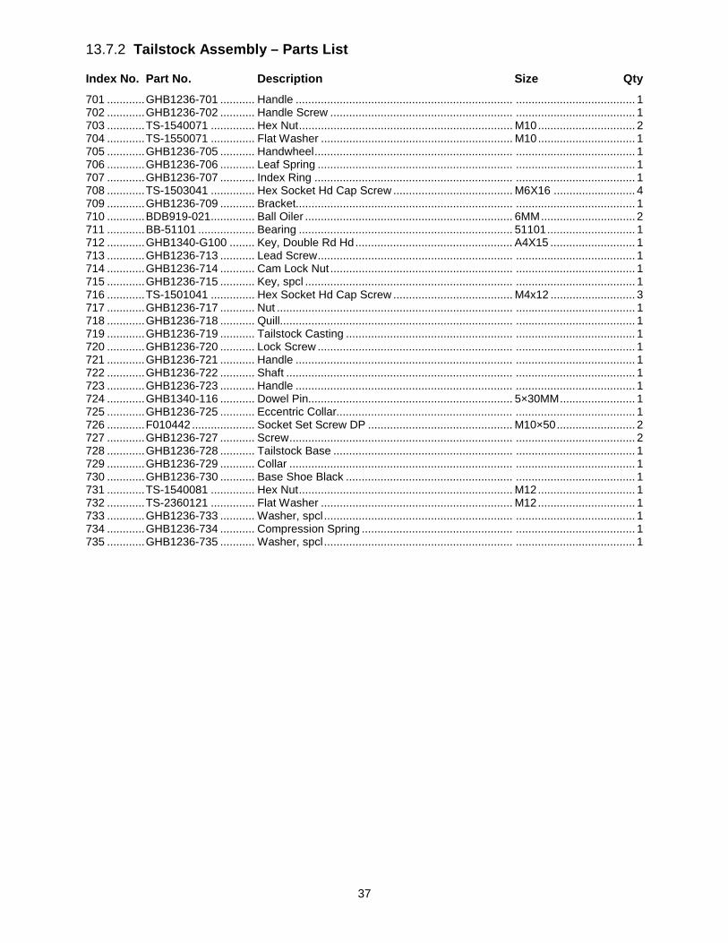
37
13.7.2 Tailstock Assembly – Parts List
Index No. Part No. Description Size Qty 701 ............ GHB1236-701 ........... Handle ..................................................................... ...................................... 1 702 ............ GHB1236-702 ........... Handle Screw .......................................................... ...................................... 1 703 ............ TS-1540071 .............. Hex Nut .................................................................... M10 ............................... 2 704 ............ TS-1550071 .............. Flat Washer ............................................................. M10 ............................... 1 705 ............ GHB1236-705 ........... Handwheel ............................................................... ...................................... 1 706 ............ GHB1236-706 ........... Leaf Spring .............................................................. ...................................... 1 707 ............ GHB1236-707 ........... Index Ring ............................................................... ...................................... 1 708 ............ TS-1503041 .............. Hex Socket Hd Cap Screw ...................................... M6X16 .......................... 4 709 ............ GHB1236-709 ........... Bracket..................................................................... ...................................... 1 710 ............ BDB919-021 .............. Ball Oiler .................................................................. 6MM .............................. 2 711 ............ BB-51101 .................. Bearing .................................................................... 51101 ............................ 1 712 ............ GHB1340-G100 ........ Key, Double Rd Hd .................................................. A4X15 ........................... 1 713 ............ GHB1236-713 ........... Lead Screw .............................................................. ...................................... 1 714 ............ GHB1236-714 ........... Cam Lock Nut .......................................................... ...................................... 1 715 ............ GHB1236-715 ........... Key, spcl .................................................................. ...................................... 1 716 ............ TS-1501041 .............. Hex Socket Hd Cap Screw ...................................... M4x12 ........................... 3 717 ............ GHB1236-717 ........... Nut ........................................................................... ...................................... 1 718 ............ GHB1236-718 ........... Quill.......................................................................... ...................................... 1 719 ............ GHB1236-719 ........... Tailstock Casting ..................................................... ...................................... 1 720 ............ GHB1236-720 ........... Lock Screw .............................................................. ...................................... 1 721 ............ GHB1236-721 ........... Handle ..................................................................... ...................................... 1 722 ............ GHB1236-722 ........... Shaft ........................................................................ ...................................... 1 723 ............ GHB1236-723 ........... Handle ..................................................................... ...................................... 1 724 ............ GHB1340-116 ........... Dowel Pin................................................................. 5×30MM ........................ 1 725 ............ GHB1236-725 ........... Eccentric Collar........................................................ ...................................... 1 726 ............ F010442 .................... Socket Set Screw DP .............................................. M10×50 ......................... 2 727 ............ GHB1236-727 ........... Screw ....................................................................... ...................................... 2 728 ............ GHB1236-728 ........... Tailstock Base ......................................................... ...................................... 1 729 ............ GHB1236-729 ........... Collar ....................................................................... ...................................... 1 730 ............ GHB1236-730 ........... Base Shoe Black ..................................................... ...................................... 1 731 ............ TS-1540081 .............. Hex Nut .................................................................... M12 ............................... 1 732 ............ TS-2360121 .............. Flat Washer ............................................................. M12 ............................... 1 733 ............ GHB1236-733 ........... Washer, spcl ............................................................ ...................................... 1 734 ............ GHB1236-734 ........... Compression Spring ................................................ ...................................... 1 735 ............ GHB1236-735 ........... Washer, spcl ............................................................ ...................................... 1

38
13.8.1 Change Gears – Exploded View
13.8.2 Change Gears – Parts List
Index No. Part No. Description Size Qty 801 ............ GHB1236-801 ........... Hex Socket Hd Cap Screw ...................................... M6X12 .......................... 2 802 ............ GHB1236-389 ........... Flat Washer, Large .................................................. M6 ................................. 2 803 ............ GHB1236-803 ........... Gear ......................................................................... 24T ................................ 1 804 ............ KF2R5508 ................. Key, Double Rd Hd .................................................. A5X8 ............................. 1 805 ............ TS-1540071 .............. Hex Nut .................................................................... M10 ............................... 2 806 ............ TS-1550071 .............. Flat Washer ............................................................. M10 ............................... 1 807 ............ GHB1236-807 ........... Compound Gear ...................................................... 120T/127T .................... 1 808 ............ BB-6003 .................... Bearing .................................................................... 6003 .............................. 2 809 ............ GHB1236-809 ........... Collar ....................................................................... ...................................... 1 810 ............ GHB1236-810 ........... Quadrant .................................................................. ...................................... 1 811 ............ GHB1236-811 ........... Screw ....................................................................... ...................................... 1 812 ............ F006033 .................... C-Retaining Ring, Int ............................................... 35MM ............................ 1 813 ............ TS-1550071 .............. Flat Washer ............................................................. M10 ............................... 1 814 ............ GHB1236-814 ........... Double End Stud ..................................................... M10X60 ........................ 1 815 ............ GHB1236-815 ........... Spacer ..................................................................... ...................................... 1 816 ............ GHB1236-816 ........... Gear ......................................................................... 48T ................................ 1 817 ............ KF2R5508 ................. Key, Double Rd Hd .................................................. A5X8MM ....................... 1 818 ............ GHB1236-818 ........... Washer .................................................................... ...................................... 1 819 ............ GHB1236-819 ........... Change gear ............................................................ 22T ................................ 1 820 ............ GHB1236-820 ........... Change gear ............................................................ 26T ................................ 1 821 ............ GHB1236-821 ........... Change gear ............................................................ 38T ................................ 1 822 ............ GHB1236-822 ........... Change gear ............................................................ 44T ................................ 1 823 ............ GHB1236-823 ........... Change gear ............................................................ 52T ................................ 1

39
13.9.1 Feed Rod Assembly – Exploded View

40
13.9.2 Feed Rod Assembly – Parts List
Index No. Part No. Description Size Qty 901 ............ GHB1236-901 ........... Lead Screw .............................................................. ...................................... 1 902 ............ GHB1236-902 ........... Rod .......................................................................... ...................................... 1 903 ............ GHB1236-903 ........... Bracket..................................................................... ...................................... 1 904 ............ GB117-6X45 ............. Taper Pin ................................................................. 6X45MM ....................... 2 905 ............ TS-1504121 .............. Hex Socket Hd Cap Screw ...................................... M8X60 .......................... 2 906 ............ BDB919-021 .............. Ball Oiler .................................................................. 6MM .............................. 2 907 ............ SB-6MM .................... Steel Ball.................................................................. 6MM .............................. 5 908 ............ TS-1523031 .............. Socket Set Screw CP .............................................. M6×10 ........................... 1 909 ............ GHB1236-909 ........... Collar ....................................................................... ...................................... 1 910 ............ GHB1236-910 ........... Feed Rod ................................................................. ...................................... 1 911 ............ GHB1236-911 ........... Key, spcl .................................................................. ...................................... 1 912 ............ PN04002408 ............. Roll Pin .................................................................... 4X25MM ....................... 1 913 ............ GHB1236-913 ........... Bracket..................................................................... ...................................... 1 914 ............ GHB1236-914 ........... Spring ...................................................................... 10X1X12MM ................. 1 915 ............ TS-1503031 .............. Hex Socket Hd Cap Screw ...................................... M6X12 .......................... 2 916 ............ GHB1236-916 ........... Bracket..................................................................... ...................................... 1 917 ............ GHB1236-917 ........... Tapered Knob .......................................................... M10X50 ........................ 1 918 ............ GHB1236-918 ........... Handle ..................................................................... ...................................... 1 919 ............ F006053 .................... C-Retaining Ring, Ext .............................................. 32MM ............................ 1 920 ............ GHB1236-920 ........... Spring ...................................................................... 1×5×30MM .................... 1 921 ............ TS-1524011 .............. Socket Set Screw .................................................... M8X8 ............................ 5 922 ............ GHB1236-922 ........... Sleeve ...................................................................... ...................................... 1 923 ............ PS042400 ................. Roll Pin .................................................................... 4X24MM ....................... 1 923a .......... GHB1236-923A ......... Taper Pin ................................................................. 4X24MM ....................... 1 924 ............ GHB1236-924 ........... Shaft ........................................................................ ...................................... 1 925 ............ BD920N-GB39 .......... Roll Pin .................................................................... 4X20MM ....................... 1 926 ............ AH25C-060 ............... Roll Pin .................................................................... 4X30MM ....................... 1 927 ............ GHB1236-927 ........... Position Piece .......................................................... ...................................... 1 928 ............ JTS315-92 ................. Phillips Pan Hd Mach Screw.................................... M4X50 .......................... 2 929 ............ GHB1236-929 ........... Switch ...................................................................... LXW5-11M .................... 2 930 ............ TS-2284202 .............. Phillips Pan Hd Mach Screw.................................... M4X20 .......................... 2 931 ............ GHB1236-931 ........... Bracket..................................................................... ...................................... 1 932 ............ GHB1236-932 ........... Cover ....................................................................... ...................................... 1 933 ............ TS-1540021 .............. Hex Nut .................................................................... M4 ................................. 4 934 ............ PS040800 ................. Roll Pin .................................................................... 4X12MM ....................... 1 935 ............ D-11 .......................... Roll Pin .................................................................... 5X25MM ....................... 1 936 ............ GHB1236-936 ........... Clutch....................................................................... ...................................... 1 938 ............ GHB1236-938 ........... Clutch....................................................................... ...................................... 1 939 ............ GHB1236-939 ........... Spring ...................................................................... 6×1×25MM .................... 4 941 ............ F012095 .................... Roll Pin .................................................................... 4X42MM ....................... 1 942 ............ TS-1523031 .............. Socket Set Screw CP .............................................. M6X10 .......................... 1 943 ............ GHB1236-943 ........... Cover ....................................................................... ...................................... 1 944 ............ BB-51104 .................. Bearing. ................................................................... 51104 ............................ 1

41
13.10.2 Motor and Change Gear Enclosure – Exploded View

42
13.10.2 Motor and Change Gear Enclosure – Parts List
Index No. Part No. Description Size Qty 1001 .......... GHB1236-1001 ......... Change Gear Enclosure .......................................... ...................................... 1 1002 .......... GHB1236-1002 ......... Door ......................................................................... ...................................... 1 1003 .......... GHB1236-1003 ......... Motor Lower Cover .................................................. ...................................... 1 1004 .......... GHB1236-1004 ......... Motor Mounting Plate .............................................. ...................................... 1 1005 .......... TS-1550071 .............. Flat Washer ............................................................. M10 ............................... 5 1006 .......... TS-1491041 .............. Hex Cap Screw ........................................................ M10X30 ........................ 3 1007 .......... ESN40-33-1 .............. Key, Double Rd Hd .................................................. 8X35MM ....................... 1 1008 .......... GHB1236-1008 ......... Pulley ....................................................................... ...................................... 1 1009 .......... TS-2276081 .............. Socket Set Screw CP .............................................. M6X8 ............................ 1 1010 .......... GHB1236-1010 ......... Motor........................................................................ 2HP/230V/1PH ............. 1 1010-1 ....... GHB1236-1010-1 ...... Start Capacitor ......................................................... 150MFD/250V ............... 1 1010-2 ....... GHB1236-1010-2 ...... Run Capacitor .......................................................... 20mF/450V ................... 1 1011 .......... TS-1550061 .............. Flat Washer ............................................................. M8 ................................. 4 1012 .......... TS-1490041 .............. Hex Cap Screw ........................................................ M8X25 .......................... 4 1013 .......... TS-1540061 .............. Hex Nut .................................................................... M8 ................................. 2 1014 .......... TS-1490081 .............. Hex Cap Screw ........................................................ M8X45 .......................... 2 1015 .......... TS-1504061 .............. Hex Socket Hd Cap Screw ...................................... M8X30 .......................... 2 1016 .......... TS-1506031 .............. Hex Socket Hd Cap Screw ...................................... M12X30 ........................ 2 1017 .......... TS-2360121 .............. Flat Washer ............................................................. M12 ............................... 2 1018 .......... TS-1492031 .............. Hex Cap Screw ........................................................ M12X35 ........................ 2 1019 .......... TS-1505041 .............. Hex Socket Hd Cap Screw ...................................... M10X30 ........................ 4 1020 .......... ZX-C34 ...................... Taper Pin ................................................................. 6X30MM ....................... 2 1021 .......... VB-A813 .................... V-Belt ....................................................................... A813 ............................. 2 1022 .......... TS-1503071 .............. Hex Socket Hd Cap Screw ...................................... M6x30 ........................... 8 1023 .......... TS-1550031 .............. Flat Washer ............................................................. M5 ................................. 9 1024 .......... TS-1550021 .............. Flat Washer ............................................................. M4 ................................. 6 1025 .......... TS-2171012 .............. Phillips Pan Hd Mach Screw.................................... M4X6 ............................ 4 1026 .......... TS-1532032 .............. Phillips Pan Hd Mach Screw.................................... M4X10 .......................... 2 1027 .......... GHB1236-1027 ......... Switch Bracket ......................................................... ...................................... 1 1028 .......... TS-1540021 .............. Hex Nut .................................................................... M4 ................................. 2 1029 .......... GHB1236-1029 ......... Switch Key ............................................................... QKS8-1 ......................... 1 1030 .......... TS-1502071 .............. Hex Socket Hd Cap Screw ...................................... M5X30 .......................... 1 1031 .......... TS-1540031 .............. Hex Nut .................................................................... M5 ................................. 2 1032 .......... GHB1236-1032 ......... Switch ...................................................................... QKS8-2 ......................... 1 1033 .......... TS-2284302 .............. Phillips Pan Hd Mach Screw.................................... M4X30 .......................... 2 1034 .......... TS-1550041 .............. Flat Washer ............................................................. M6 ................................. 2 1035 .......... TS-1503031 .............. Hex Socket Hd Cap Screw ...................................... M6X12 .......................... 1 1036 .......... TS-1550041 .............. Flat Washer ............................................................. M6 ................................. 3 1037 .......... GHB1236-1037 ......... Door Cover .............................................................. ...................................... 1 1038 .......... TS-1541021 .............. Nylon Lock Hex Nut ................................................. M6 ................................. 1 1039 .......... GHB1236-1039 ......... Door Latch Assy ...................................................... ...................................... 1
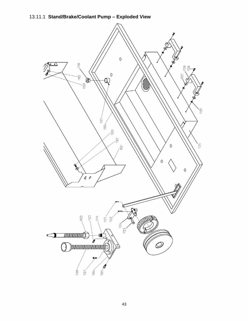
43
13.11.1 Stand/Brake/Coolant Pump – Exploded View
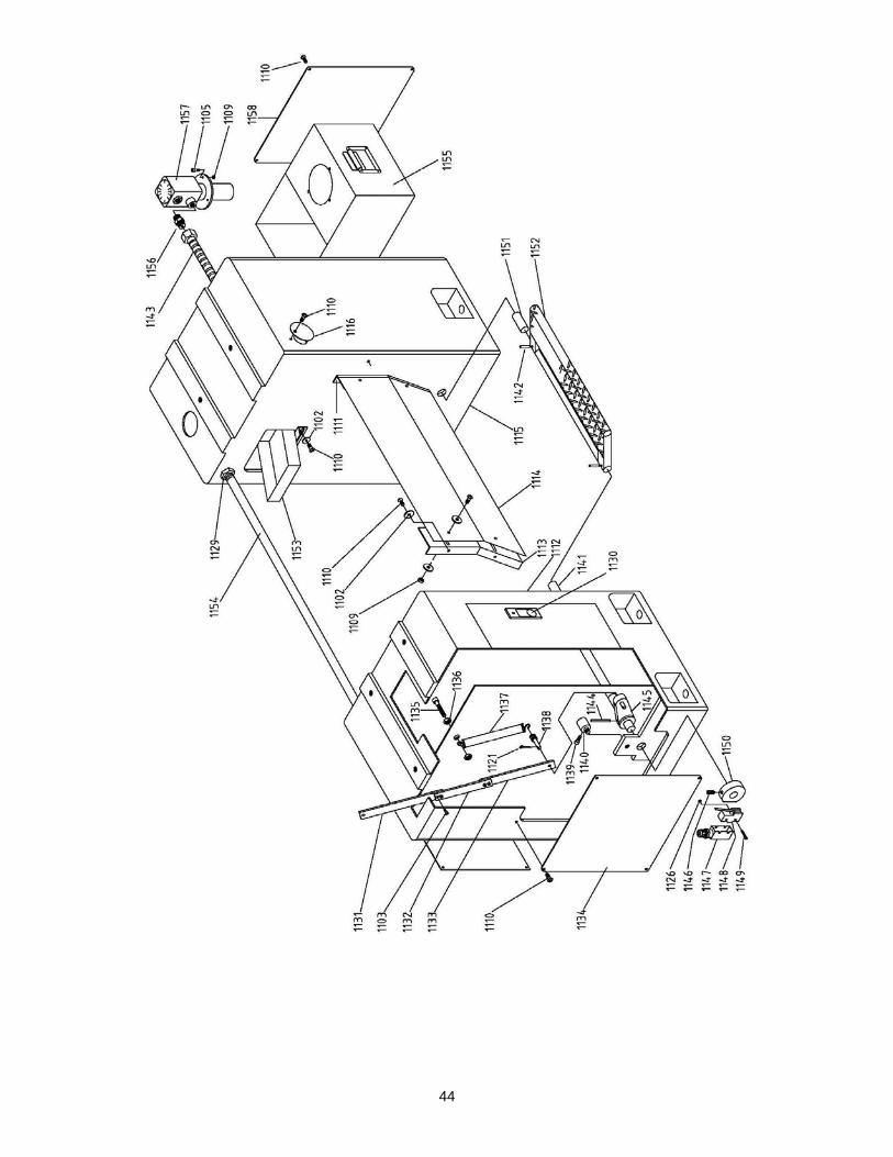
44
45
13.11.2 Stand/Brake/Coolant Pump – Parts List
Index No. Part No. Description Size Qty 1101 .......... GHB1236-1101 ......... Splash Guard ........................................................... ...................................... 1 1102 .......... TS-1550041 .............. Flat Washer ............................................................. M6 ............................... 16 1103 .......... TS-1503021 .............. Hex Socket Hd Cap Screw ...................................... M6X10 .......................... 4 1104 .......... GHB1236-1104 ......... Oil Pan ..................................................................... ...................................... 1 1105 .......... TS-1503051 .............. Hex Socket Hd Cap Screw ...................................... M6X20 .......................... 5 1106 .......... GHB1236-1106 ......... Bracket..................................................................... ...................................... 1 1107 .......... JBOS5-56 .................. Hex Socket Hd Cap Screw ...................................... M5X15 .......................... 4 1108 .......... GHB1236-1108 ......... Work Lamp .............................................................. ...................................... 1 1109 .......... TS-1540041 .............. Hex Nut .................................................................... M6 ............................... 10 1110 .......... TS-1534032 .............. Phillips Pan Hd Mach Screw.................................... M6X10 ........................ 26 1111 .......... GHB1236-1111 ......... Right Bracket ........................................................... ...................................... 1 1112 .......... GHB1236-1112 ......... Left Cabinet ............................................................. ...................................... 1 1113 .......... GHB1236-1113 ......... Left Bracket.............................................................. ...................................... 1 1114 .......... GHB1236-1114 ......... Back Plate................................................................ ...................................... 1 1115 .......... GHB1236-1115 ......... Right Cabinet ........................................................... ...................................... 1 1116 .......... GHB1236-1116 ......... Cover ....................................................................... ...................................... 4 1117 .......... TS-1501011 .............. Hex Socket Hd Cap Screw ...................................... M4X6 ............................ 1 1118 .......... GHB1236-1118 ......... Coolant Hose Collar................................................. ...................................... 1 1119 .......... GHB1236-1119 ......... Coolant Fitting.......................................................... ...................................... 1 1120 .......... GHB1236-1120 ......... Coolant Nozzle ........................................................ ...................................... 1 1121 .......... GHB1236-1121 ......... Cotter Pin ................................................................. 3X16MM ....................... 2 1122 .......... D-11 .......................... Roll Pin .................................................................... 5X25MM ....................... 1 1123 .......... GHB1236-1123 ......... Clevis Pin ................................................................. ...................................... 1 1124 .......... GHB1236-1124 ......... Rocker .................................................................... ........................................ 1125 .......... GHB1236-1125 ......... Oil Tray .................................................................... ...................................... 1 1126 .......... TS-1534042 .............. Phillips Pan Hd Mach Screw.................................... M6X12 .......................... 4 1127 .......... TS-1550041 .............. Flat Washer ............................................................. M6 ................................. 4 1128 .......... GHB1236-1128 ......... Handle ..................................................................... ...................................... 2 1129 .......... GHB1236-1129 ......... Nut ........................................................................... M16X1.5 ....................... 1 1130 .......... GHB1236-1130 ......... Door Latch Assy ...................................................... ...................................... 1 1131 .......... GHB1236-1131 ......... Brake Linkage/Upper ............................................... ...................................... 1 1132 .......... GHB1236-1132 ......... Brake Linkage/Middle .............................................. ...................................... 1 1133 .......... GHB1236-1133 ......... Brake Linkage/Lower ............................................... ...................................... 1 1134 .......... GHB1236-1134 ......... Cover ....................................................................... ...................................... 2 1135 .......... TS-1505041 .............. Hex Socket Hd Cap Screw ...................................... M10X30 ........................ 1 1136 .......... TS-1540071 .............. Hex Nut .................................................................... M10 ............................... 2 1137 .......... GHB1236-1137 ......... Drawspring............................................................... ...................................... 1 1138 .......... GHB1236-1138 ......... Pin............................................................................ ...................................... 1 1139 .......... TS-1503091 .............. Hex Socket Hd Cap Screw ...................................... M6X40 .......................... 1 1140 .......... GHB1236-1140 ......... Shaft ........................................................................ ...................................... 1 1141 .......... GHB1236-1141 ......... Shaft ........................................................................ ...................................... 1 1142 .......... 3P12312 .................... Roll Pin .................................................................... 5X28MM ....................... 4 1143 .......... GHB1236-1143 ......... Flexible Metal Tube ................................................. 2M ................................. 1 1144 .......... EHB916V-08-1 .......... Roll Pin .................................................................... 5X40MM ....................... 1 1145 .......... GHB1236-1145 ......... Rocker ..................................................................... ...................................... 1 1146 .......... TS-1523041 .............. Socket Set Screw CP .............................................. M6X12 .......................... 1 1147 .......... GHB1236-1147 ......... Limit Switch Cover ................................................... ...................................... 1 1148 .......... GHB1236-1148 ......... Limit Switch.............................................................. YBLXW-5/11N1 ............ 1 1149 .......... PS1652T-105 ............ Phillips Pan Hd Mach Screw.................................... M4X40 .......................... 2 1150 .......... GHB1236-1150 ......... Rocker Cam ............................................................. ...................................... 1 1151 .......... GHB1236-1151 ......... Shaft ........................................................................ ...................................... 1 1152 .......... GHB1236-1152 ......... Brake Pedal ............................................................. ...................................... 1 1153 .......... GHB1236-1153 ......... Funnel ...................................................................... ...................................... 1 1154 .......... GHB1236-1154 ......... Steel Tube ............................................................... ...................................... 1 1155 .......... GHB1236-1155 ......... Water Tank .............................................................. ...................................... 1 1156 .......... GHB1236-1156 ......... Connector ................................................................ ...................................... 1 1157 .......... GHB1236-1157 ......... Pump ....................................................................... ...................................... 1 1158 .......... GHB1236-1158 ......... Cover ....................................................................... ...................................... 1 .................. JET-138 ..................... JET Logo (not shown) ............................................. 138x57 mm ................... 1

46
13.12.1 Electrical Box Assembly – Exploded View
47
13.12.2 Electrical Box Assembly – Parts List
Index No. Part No. Description Size Qty 1201 .......... GHB1236-1201 ......... Circuit Breaker ......................................................... DZ47-63 -1PC3 ............. 1 1202 .......... GHB1236-1202 ......... Circuit Breaker ......................................................... DZ47-63-2PD16 ............ 1 1203 .......... GHB1236-1203 ......... Transformer ............................................................. JBK5-100VA-TH ........... 1 1204 .......... TS-2171012 .............. Phillips Pan Head Mach Screw ............................... M4X6 .......................... 15 1205 .......... GHB1236-1205 ......... Rail Clip ................................................................... ...................................... 1 1206 .......... GHB1236-1206 ......... Rubber Cushing ....................................................... ...................................... 4 1207 .......... GHB1236-1207 ......... Cover ....................................................................... ...................................... 1 1208 .......... TS-1550021 .............. Flat Washer ............................................................. M4 ................................. 6 1209 .......... TS-1501031 .............. Hex Socket Hd Cap Screw ...................................... M4×10 ........................... 6 1210 .......... TS-1540031 .............. Hex Nut .................................................................... M5 ................................. 4 1211 .......... GHB1236-1211 ......... Copper Sheet .......................................................... ...................................... 1 1212 .......... TS-1532042 .............. Phillips Pan Head Mach Screw ............................... M4X12 .......................... 5 1213 .......... GHB1236-1213 ......... Graphic Plate - Ground ............................................ ...................................... 1 1214 .......... GHB1236-1214 ......... Strain Relief ............................................................. M16X1.5 ....................... 5 1215 .......... GHB1236-1215 ......... Mounting Plate ......................................................... ...................................... 1 1216 .......... GHB1236-1216 ......... Strain Relief ............................................................. M20X1.5 ....................... 2 1217 .......... GHB1236-1217 ......... DIN Rall Lower......................................................... ...................................... 1 1218 .......... GHB1236-1218 ......... Rail Clip ................................................................... ...................................... 1 1220 .......... GHB1236-1220 ......... AC Contactor ........................................................... CJX2S-0901-24V .......... 3 1222 .......... GHB1236-1222 ......... Contactor Relay ....................................................... JZC4-40-24V ................ 1 1223 .......... TS-1502031 .............. Hex Socket Hd Cap Screw ...................................... M5X12 .......................... 4 1224 .......... GHB1236-1224 ......... Rail Clip ................................................................... ...................................... 1 1225 .......... GHB1236-1225 ......... Electric Box .............................................................. ...................................... 1 1226 .......... GHB1236-1226 ......... Power Switch ........................................................... LW26-20 ....................... 1 1227 .......... GHB1236-1227 ......... E-Stop Button .......................................................... XB2-BS545 ................... 1 1228 .......... GHB1236-1228 ......... Jog Button ............................................................... LAY5-22D/23 ................ 1 1229 .......... GHB1236-1229 ......... Button switch ........................................................... LAY3-11/2 ....................... 1230 .......... GHB1236-1230 ......... Power Light .............................................................. AD62-22D/S 23/24V ..... 1 1231 .......... TS-1540021 .............. Hex Nut .................................................................... M4 ................................. 3 1232 .......... GHB1236-1232 ......... Name Plate .............................................................. ...................................... 1 1233 .......... GHB1236-1233 ......... Motor Upper Cover .................................................. ...................................... 1

48
13.13.1 Steady Rest and Follow Rest – Parts List

49
13.13.2 Steady Rest and Follow Rest – Parts List
Index No. Part No. Description Size Qty 1301 .......... GHB1236-1301 ......... Pinned Knob ............................................................ ...................................... 3 1302 .......... B-56 ........................... Roll Pin .................................................................... 3X20MM ....................... 3 1303 .......... GHB1236-1303 ......... Collar ....................................................................... ...................................... 3 1304 .......... GHB1236-1304 ......... Jack Screw .............................................................. ...................................... 3 1305 .......... GHB1236-1305 ......... Finger Slide.............................................................. ...................................... 3 1306 .......... BB-625ZZ .................. Bearing .................................................................... 625ZZ ........................... 3 1306a ........ F004038 .................... Dowel Pin................................................................. 5X16MM ....................... 3 1307 .......... GHB1236-1307 ......... Knurled Thumb Knob ............................................... ...................................... 1 1308 .......... TS-1523031 .............. Socket Set Screw CP .............................................. M6X10 .......................... 3 1309 .......... GHB1236-1309 ......... Steady Rest Upper Body ......................................... ...................................... 1 1310 .......... F010438 .................... Socket Set Screw DP .............................................. M6×16 ........................... 3 1311 .......... TS-1540041 .............. Hex Nut .................................................................... M6 ................................. 3 1312 .......... GHB1236-1312 ......... Pivot Stud ................................................................ ...................................... 1 1313 .......... 5217841 .................... Roll Pin .................................................................... 4×20MM ........................ 1 1314 .......... GB119-N6X20 ........... Dowel Pin................................................................. 6×20MM ........................ 1 1315 .......... GHB1236-1315 ......... Steady Rest Lower Body ......................................... ...................................... 1 1316 .......... GHB1236-1316 ......... Clamp Block............................................................. ...................................... 1 1317 .......... GHB1236-1317 ......... T-Bolt ....................................................................... M12X60 ........................ 1 1318 .......... TS-1540081 .............. Hex Nut .................................................................... M12 ............................... 1 1319 .......... TS-2360121 .............. Flat Washer ............................................................. M12 ............................... 1 1401 .......... TS-209203 ................ Roll Pin .................................................................... 3X20MM ....................... 2 1402 .......... GHB1236-1402 ......... Pinned Knob ............................................................ ...................................... 2 1403 .......... GHB1236-1403 ......... Collar ....................................................................... ...................................... 2 1404 .......... GHB1236-1404 ......... Jack Screw .............................................................. ...................................... 2 1405 .......... GHB1236-1405 ......... Finger Slide.............................................................. ...................................... 2 1406 .......... GHB1236-1406 ......... Brass Finger ............................................................ ...................................... 2 1407 .......... TS-1523031 .............. Socket Set Screw CP .............................................. M6X10 .......................... 2 1408 .......... TS-1540041 .............. Hex Nut .................................................................... M6 ................................. 2 1409 .......... F010438 .................... Socket Set Screw DP .............................................. M6×16 ........................... 2 1410 .......... GHB1236-1410 ......... Follow Rest Body ..................................................... ...................................... 1 1411 .......... TS-1504081 .............. Hex Socket Hd Cap Screw ...................................... M8×40 ........................... 2
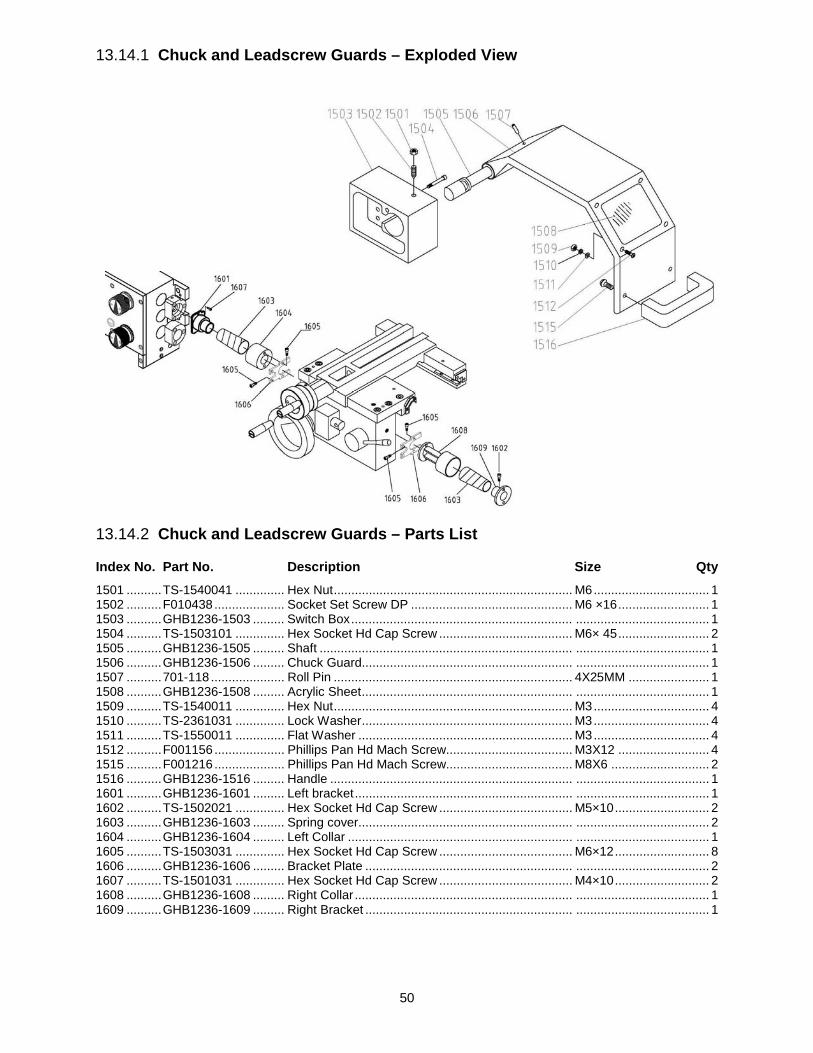
50
13.14.1 Chuck and Leadscrew Guards – Exploded View
13.14.2 Chuck and Leadscrew Guards – Parts List
Index No. Part No. Description Size Qty 1501 .......... TS-1540041 .............. Hex Nut .................................................................... M6 ................................. 1 1502 .......... F010438 .................... Socket Set Screw DP .............................................. M6 ×16 .......................... 1 1503 .......... GHB1236-1503 ......... Switch Box ............................................................... ...................................... 1 1504 .......... TS-1503101 .............. Hex Socket Hd Cap Screw ...................................... M6× 45 .......................... 2 1505 .......... GHB1236-1505 ......... Shaft ........................................................................ ...................................... 1 1506 .......... GHB1236-1506 ......... Chuck Guard............................................................ ...................................... 1 1507 .......... 701-118 ..................... Roll Pin .................................................................... 4X25MM ....................... 1 1508 .......... GHB1236-1508 ......... Acrylic Sheet ............................................................ ...................................... 1 1509 .......... TS-1540011 .............. Hex Nut .................................................................... M3 ................................. 4 1510 .......... TS-2361031 .............. Lock Washer ............................................................ M3 ................................. 4 1511 .......... TS-1550011 .............. Flat Washer ............................................................. M3 ................................. 4 1512 .......... F001156 .................... Phillips Pan Hd Mach Screw.................................... M3X12 .......................... 4 1515 .......... F001216 .................... Phillips Pan Hd Mach Screw.................................... M8X6 ............................ 2 1516 .......... GHB1236-1516 ......... Handle ..................................................................... ...................................... 1 1601 .......... GHB1236-1601 ......... Left bracket .............................................................. ...................................... 1 1602 .......... TS-1502021 .............. Hex Socket Hd Cap Screw ...................................... M5×10 ........................... 2 1603 .......... GHB1236-1603 ......... Spring cover............................................................. ...................................... 2 1604 .......... GHB1236-1604 ......... Left Collar ................................................................ ...................................... 1 1605 .......... TS-1503031 .............. Hex Socket Hd Cap Screw ...................................... M6×12 ........................... 8 1606 .......... GHB1236-1606 ......... Bracket Plate ........................................................... ...................................... 2 1607 .......... TS-1501031 .............. Hex Socket Hd Cap Screw ...................................... M4×10 ........................... 2 1608 .......... GHB1236-1608 ......... Right Collar .............................................................. ...................................... 1 1609 .......... GHB1236-1609 ......... Right Bracket ........................................................... ...................................... 1

51
13.15.1 Accessories – Exploded View

52
13.15.2 Accessories – Parts List
Index No. Part No. Description Size Qty 1701 .......... GHB1236-1701 ......... 3-Jaw Chuck Assembly ........................................... 160MM-D4 .................... 1 1701-1 ....... TS-1503031 .............. Hex Socket Hd Cap Screw ...................................... M6X12 .......................... 3 1701-2 ....... GHB1236-1701-2 ...... Camlock Stud .......................................................... ...................................... 3 1701-3 ....... GHB1236-1701-3 ...... 3-Jaw Chuck Key ..................................................... ...................................... 1 1701-4 ....... GHB1236-1701-4 ...... 3-Jaw chuck Body.................................................... ...................................... 1 1701-5 ....... GHB1236-1701-5 ...... Internal Jaws 3PCS Set ........................................... ...................................... 1 1701-6 ....... GHB1236-1701-6 ...... Reverse Jaws 3PCS Set ......................................... ...................................... 1 1702 .......... GHB1236-1702 ......... 4-Jaw Chuck Assembly ........................................... 200MM-D4 .................... 1 1702-1 ....... TS-1503031 .............. Hex Socket Hd Cap Screw ...................................... M6X12 .......................... 3 1702-2 ....... GHB1236-1702-2 ...... Camlock Stud .......................................................... ...................................... 3 1702-3 ....... GHB1236-1702-3 ...... 4-Jaw Chuck Key ..................................................... ...................................... 1 1702-4 ....... GHB1236-1702-4 ...... 4-Jaw Chuck Body ................................................... ...................................... 1 1702-5 ....... GHB1236-1702-5 ...... Jaws 4PCS Set ........................................................ ...................................... 1 1703 .......... GHB1236-1703 ......... Face Plate Assembly ............................................... 250MM .......................... 1 1703-1 ....... TS-1503031 .............. Hex Socket Hd Cap Screw ...................................... M6X12 .......................... 3 1703-2 ....... GHB1236-1703-2 ...... Camlock Stud .......................................................... ...................................... 3 1703-3 ....... GHB1236-1703-3 ...... Face Plate Body ...................................................... ...................................... 1 1704 .......... GHB1236-TBC .......... Tool Box Complete * ................................................ ...................................... 1 1705 .......... GHB1236-1705 ......... Key for Cam Locks * ................................................ ...................................... 1 1706 .......... GHB1236-1706 ......... Oil Gun * .................................................................. ...................................... 1 1707 .......... GHB1236-1707 ......... Dead Center * .......................................................... MT3 ............................... 1 1708 .......... GHB1236-1707 ......... Dead Center * .......................................................... MT3 ............................... 1 1709 .......... GHB1236-1709 ......... Tapered Reducing Sleeve * ..................................... MT5-MT3 ...................... 1 1710 .......... JHL610-901 ............... Hex Wrench *........................................................... 2MM .............................. 1 1711 .......... TS-152704 ................ Hex Wrench *........................................................... 3MM .............................. 1 1712 .......... TS-152705 ................ Hex Wrench *........................................................... 4MM .............................. 1 1713 .......... TS-152706 ................ Hex Wrench *........................................................... 5MM .............................. 1 1714 .......... TS-152707 ................ Hex Wrench *........................................................... 6MM .............................. 1 1715 .......... GHB1236-1715 ......... Live Center * ............................................................ MT3 ............................... 1 1716…..GH1340A-TBCP-16-04 ... Open End Wrench * ................................................. 10-12MM ....................... 1 1717 .......... JBOS5-105 ................ Open End Wrench * ................................................. 14-17MM ....................... 1 1718……GH1340A-TBCP-16-06 . Open End Wrench * ................................................. 17-19MM ....................... 1 1719 .......... ZX-OP-15 .................. Cross Point Screwdriver * ........................................ 3‘’ .................................. 1 1720 .......... ZX-OP-14 .................. Flat Blade Screwdriver * .......................................... 3‘’ .................................. 1 1721 .......... GHB1236-1721 ......... Sizing Block Assembly............................................. ...................................... 6 1721-1 ....... F008920 .................... Hex Cap Bolt............................................................ M14x50 ......................... 6 1721-2 ....... TS-154009 ................ Hex Nut .................................................................... M14 ............................. 12 1721-3 ....... TS-155009 ................ Flat Washer ............................................................. M14 ............................. 12 1721-4 ....... GHB1236-1721-4 ...... Washer, spcl ............................................................ ...................................... 6 * included in GHB1236-TBC, Tool Box

53
14.0 Wiring Diagram for GHB-1236

54
15.0 Warranty and service JET warrants every product it sells against manufacturers’ defects. If one of our tools needs service or repair, please contact Technical Service by calling 1-800-274-6846, 8AM to 5PM CST, Monday through Friday.
Warranty Period The general warranty lasts for the time period specified in the literature included with your product or on the official JET branded website.
• JET products carry a limited warranty which varies in duration based upon the product. (See chart below) • Accessories carry a limited warranty of one year from the date of receipt. • Consumable items are defined as expendable parts or accessories expected to become inoperable within a
reasonable amount of use and are covered by a 90 day limited warranty against manufacturer’s defects.
Who is Covered This warranty covers only the initial purchaser of the product from the date of delivery.
What is Covered This warranty covers any defects in workmanship or materials subject to the limitations stated below. This warranty does not cover failures due directly or indirectly to misuse, abuse, negligence or accidents, normal wear-and-tear, improper repair, alterations or lack of maintenance. JET woodworking machinery is designed to be used with Wood. Use of these machines in the processing of metal, plastics, or other materials may void the warranty. The exceptions are acrylics and other natural items that are made specifically for wood turning.
Warranty Limitations Woodworking products with a Five Year Warranty that are used for commercial or industrial purposes default to a Two Year Warranty. Please contact Technical Service at 1-800-274-6846 for further clarification.
How to Get Technical Support Please contact Technical Service by calling 1-800-274-6846.Please note that you will be asked to provide proof of initial purchase when calling. If a product requires further inspection, the Technical Service representative will explain and assist with any additional action needed. JET has Authorized Service Centers located throughout the United States. For the name of an Authorized Service Center in your area call 1-800-274-6846 or use the Service Center Locator on the JET website.
More Information JET is constantly adding new products. For complete, up-to-date product information, check with your local distributor or visit the JET website.
How State Law Applies This warranty gives you specific legal rights, subject to applicable state law.
Limitations on This Warranty JET LIMITS ALL IMPLIED WARRANTIES TO THE PERIOD OF THE LIMITED WARRANTY FOR EACH PRODUCT. EXCEPT AS STATED HEREIN, ANY IMPLIED WARRANTIES OF MERCHANTABILITY AND FITNESS FOR A PARTICULAR PURPOSE ARE EXCLUDED. SOME STATES DO NOT ALLOW LIMITATIONS ON HOW LONG AN IMPLIED WARRANTY LASTS, SO THE ABOVE LIMITATION MAY NOT APPLY TO YOU. JET SHALL IN NO EVENT BE LIABLE FOR DEATH, INJURIES TO PERSONS OR PROPERTY, OR FOR INCIDENTAL, CONTINGENT, SPECIAL, OR CONSEQUENTIAL DAMAGES ARISING FROM THE USE OF OUR PRODUCTS. SOME STATES DO NOT ALLOW THE EXCLUSION OR LIMITATION OF INCIDENTAL OR CONSEQUENTIAL DAMAGES, SO THE ABOVE LIMITATION OR EXCLUSION MAY NOT APPLY TO YOU. JET sells through distributors only. The specifications listed in JET printed materials and on official JET website are given as general information and are not binding. JET reserves the right to effect at any time, without prior notice, those alterations to parts, fittings, and accessory equipment which they may deem necessary for any reason whatsoever. JET® branded products are not sold in Canada by JPW Industries, Inc.
Product Listing with Warranty Period 90 Days – Parts; Consumable items 1 Year – Motors; Machine Accessories 2 Year – Metalworking Machinery; Electric Hoists, Electric Hoist Accessories; Woodworking Machinery used for industrial or commercial purposes 5 Year – Woodworking Machinery Limited Lifetime – JET Parallel clamps; VOLT Series Electric Hoists; Manual Hoists; Manual Hoist Accessories; Shop Tools; Warehouse & Dock products; Hand Tools; Air Tools NOTE: JET is a division of JPW Industries, Inc. References in this document to JET also apply to JPW Industries, Inc., or any of its successors in interest to the JET brand.

55
This page intentionally left blank.

56
427 New Sanford Road LaVergne, Tennessee 37086
Phone: 800-274-6848 www.jettools.com