Embed Size (px)
Citation preview

EN.GOLD.O&M.001
OPERATION AND MAINTENANCE INSTRUCTIONS FOR THE GOLD RX/PX/SD, GENERATION A
Applicable to program version 1.21 and newer versions
GOLD RXGOLD PX
The document was originally written in Swedish.
GOLD SD

GB.GOLDSKE.160208
1. Safety Instructions ................... 31.1 Safety Isolating Switch/Main Switch ..........31.2 Risks .......................................................31.3 Safety Guards ..........................................31.4 Glycol ......................................................3
2. General ..................................... 42.1 Handling of air handling units before commissioning ..............................................42.2 Range of Application ................................42.3 Mechanical Design ...................................42.4 Control System ........................................42.5 Environm. Documentation ........................42.6 Type of Heat Exchanger ............................42.7 Components of Air Handling Units ...........5
2.7.1 GOLD RX one-piece air handling unit with rotary heat exchanger .....................................................52.7.2 GOLD PX one-piece air handling unit with plate heat exchanger .....................................................62.7.3 GOLD SD separate supply air and return air handling units, sizes 05-08 ....................................72.7.4 GOLD SD separate supply air and return air handling units, size 11/12 ......................................82.7.5 GOLD SD separate supply air and return air handling units, Sizes 14-100, with coil heat exchangers ...........................................................9
3. Commissioning ....................... 103.1 General ..................................................103.3 To Adjust the Pressure Balance ................ 11
3.3.1 General ......................................................113.3.2. Ensure correct direction of air leakage .......12
4. IQnavigator Hand-held Terminal and Image Management ........... 134.1 IQnavigator Hand-held Terminal .............13
4.1.1 General ......................................................134.1.2 How to use the micro terminal ...................144.1.3 Buttons ......................................................154.1.4 Indicator symbols .......................................154.1.5 Keyboard ...................................................16
4.2 Image Management ...............................174.2.1 Selection of language .................................184.2.2 Dashboard .................................................18
4.2.2.1 General ................................................184.2.2.2 To change the operating mode .............184.2.2.3 Alarm log .............................................184.2.2.4 Log diagram .........................................194.2.2.5 Flow chart ............................................19
5. User (local) .............................. 205.1 Image Management ...............................205.2 Filter Calibration .....................................215.3 Functions ..............................................22
5.3.1 Airflow.......................................................225.3.1.1 Status ..................................................225.3.1.2 Operation level .....................................225.3.1.3 Air adjustment .....................................22
5.3.2 Temperature ...............................................235.3.2.1 Status ..................................................235.3.2.2 Settings ................................................23
5.3.3 Time and schedule .....................................255.3.3.1 Time and date ......................................255.3.3.3 Day schedule ........................................265.3.3.4 Exceptions schedule .............................265.3.3.5 Calendar 1 and 2..................................275.3.3.6 Prolonged operation .............................27
5.3.4 Energy monitoring .....................................285.3.5 Filters .........................................................285.3.6 Software ....................................................285.3.7 Language ...................................................28
6. Installation .............................. 296.1 Image Management ...............................29
6.2 Main Setup ............................................306.3 Filter Calibration .....................................306.4 Functions ...............................................31
6.4.1 Airflow.......................................................316.4.1.1 Status ..................................................316.4.1.2 Operation level .....................................316.4.1.3 Regulation mode ..................................326.4.1.4 Optimize ..............................................336.4.1.5 Set point displacement .........................336.4.1.6 Unit .....................................................336.4.1.7 Air adjustment .....................................336.4.1.8 Outdoor air compensation ....................346.4.1.9 Booster diffusers ..................................35
6.4.1.10 Automatic operation .............................356.4.2 Temperature ...............................................36
6.4.2.1 Status ..................................................366.4.2.2 Settings ................................................366.4.2.3 Regulation mode ..................................396.4.2.4 Unit of temperature..............................396.4.2.5 Set point displacement .........................396.4.2.6 Neutral zone ........................................406.4.2.7 External temperature sensors ................406.4.2.8 Regulation sequence ............................416.4.2.9 Min. exhaust air ...................................426.4.2.10 Morning Boost ...................................436.4.2.11 Heating Boost ....................................436.4.2.12 Cooling Boost ....................................446.4.2.13 Intermittent night heat .......................456.4.2.14 Summer night cool .............................466.4.2.15 Down regulation (airflow/pressure) .....47
6.4.3 Time and schedule .....................................486.4.3.1 Time and date ......................................486.4.3.2 Schedule settings .................................486.4.3.3 Day schedule ........................................496.4.3.4 Exceptions schedule .............................496.4.3.5 Calendar 1 and 2..................................506.4.3.6 Prolonged operation .............................50
6.4.4 Energy monitoring .....................................516.4.5 Filters .........................................................516.4.6 Software ....................................................516.4.7 Language ...................................................516.4.8 Alarm settings ............................................52
6.4.8.1 Fire alarms ............................................526.4.8.2 External alarms .....................................536.4.8.3 Temperature protection ........................536.4.8.4 Temperature alarm limits ......................546.4.8.5 Service period.......................................546.4.8.6 Alarm priority .......................................54
6.4.9 Log ............................................................556.4.9.1 Continuous log ....................................556.4.9.2 Log sender ...........................................55
6.4.10 Air handling unit .....................................566.4.10.1 Settings ..............................................566.4.10.2 Fan status...........................................576.4.10.3 Operation time ...................................576.4.10.4 VOC/CO2 sensor .................................576.4.10.5 Automatic functions ...........................57
6.4.11 Heat.........................................................586.4.11.1 Status ................................................586.4.11.2 Pre-heat .............................................586.4.11.3 Extra regulation sequences 1 and 2 .....596.4.11.4 Reheat ...............................................606.4.11.5 Xzone ................................................606.4.11.6 Electric air heater ................................616.4.11.7 Season Heat .......................................61
6.4.11.8 Automatic functions ..............................616.4.12 Cool.........................................................62
6.4.12.1 Status ................................................626.4.12.2 Extra regulation sequences 1 and 2 .....626.4.12.3 Cool ...................................................636.4.12.4 Xzone ................................................646.4.12.5 Delay time ..........................................656.4.12.6 Outdoor air limits ...............................656.4.12.7 Airflow, limits .....................................65
6.4.13 Heat/Cool recovery ...................................666.4.13.1 Status ................................................666.4.13.2 Carry over control...............................666.4.13.3 Defrost ...............................................67
6.4.13.4 Calibration/Optimization (GOLD PX) ...686.4.13.5 Automatic functions ...........................68
6.4.15 Humidity ..................................................696.4.15.1 Status ................................................696.4.15.2 Humidifying .......................................696.4.15.3 Dehumidifying ...................................706.4.15.4 Humidifier alarm ................................70
6.4.16 ReCO2 ................................................................................................71
6.4.17 All Year Comfort ......................................726.4.19 Inputs/Outputs .........................................736.4.20 Communication .......................................74
6.4.20.1 External Port B ....................................746.4.20.2 Wireless LAN ......................................746.4.20.3 E-mail ................................................756.4.20.4 EIA-485 ..............................................756.4.20.5 Modbus TCP ......................................756.4.20.6 BACnet IP...........................................756.4.20.7 EXOline TCP .......................................766.4.20.8 Operation level communication ..........76
6.4.21 Base setting .............................................776.4.22. Users.......................................................776.4.23 Notes .......................................................786.4.24 Manual test ..............................................786.4.25 IQnavigator (hand-held terminal) ............................................79
6.4.25.1 Connect to IQlogic .............................796.4.25.2 Backlight brightness ...........................796.4.25.3 Acoustics ...........................................79
7. Maintenance ........................... 807.1 Filter Change .........................................80
7.1.1 Removing filters .........................................807.1.2 Installing new filters ...................................80
7.2 Cleaning and Inspection .........................817.2.1 General ......................................................817.2.2 Filter spaces ...............................................817.2.3 Heat exchangers ........................................817.2.4 Fans and fan spaces ...................................81
7.3 General inspection and functionality check .......................................81
8. Alarms and Troubleshooting . 828.1 General ..................................................82
8.1.1 A and B alarms ...........................................828.1.2 Resetting the alarm ....................................828.1.3 Changing alarm settings .............................82
8.2 Alarm Descriptions with Factory Settings 83
9. Information Messages ........... 95
10. Technical Data ...................... 9710.1 Dimensions, GOLD RX one-piece air handling unit with rotary heat exchanger ...........................9710.2 Dimensions, GOLD PX one-piece air handling unit with plate heat exchanger ..........................10010.3 Dimensions, separate GOLD SD supply air and return air handling units ....................................101
10.5 Connection to wiring terminals ..........10510.6 Electrical data .....................................106
10.6.1 Air handling unit ....................................10610.6.2 Fans .......................................................10710.6.3 Electrical equipment cubicle ...................10810.6.4 Motor in rotary heat exchanger ..............109
10.6.4.1 Standard rotor .................................10910.6.4.2 Recosorptic rotor ..............................109
10.6.5 Control inaccuracy .................................10910.7 Volume of glycol/water SD coil heat exchangers ................................................109
www.swegon.com 3We reserve the right to alter specifications without notice.
EN.GOLD.O&M.001
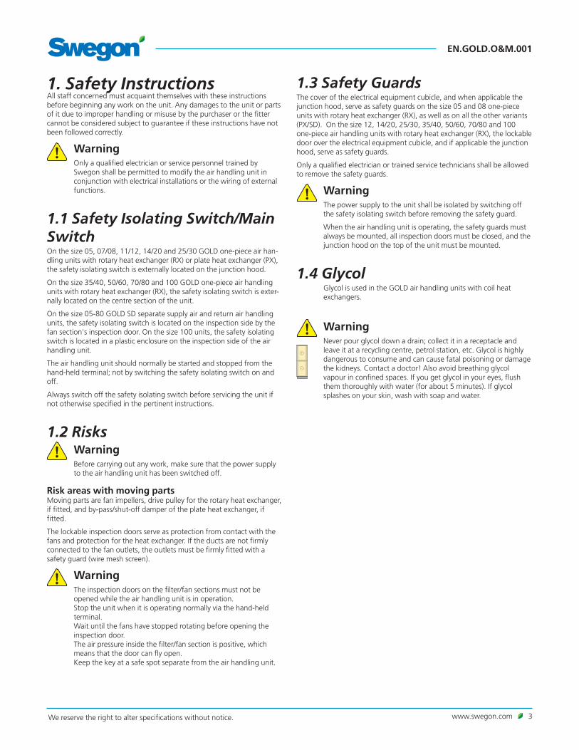
1.3 Safety GuardsThe cover of the electrical equipment cubicle, and when applicable the junction hood, serve as safety guards on the size 05 and 08 one-piece units with rotary heat exchanger (RX), as well as on all the other variants (PX/SD). On the size 12, 14/20, 25/30, 35/40, 50/60, 70/80 and 100 one-piece air handling units with rotary heat exchanger (RX), the lockable door over the electrical equipment cubicle, and if applicable the junction hood, serve as safety guards.
Only a qualified electrician or trained service technicians shall be allowed to remove the safety guards.
WarningThe power supply to the unit shall be isolated by switching off the safety isolating switch before removing the safety guard.
When the air handling unit is operating, the safety guards must always be mounted, all inspection doors must be closed, and the junction hood on the top of the unit must be mounted.
1.4 GlycolGlycol is used in the GOLD air handling units with coil heat exchangers.
Warning Never pour glycol down a drain; collect it in a receptacle and leave it at a recycling centre, petrol station, etc. Glycol is highly dangerous to consume and can cause fatal poisoning or damage the kidneys. Contact a doctor! Also avoid breathing glycol vapour in confined spaces. If you get glycol in your eyes, flush them thoroughly with water (for about 5 minutes). If glycol splashes on your skin, wash with soap and water.
1. Safety InstructionsAll staff concerned must acquaint themselves with these instructions before beginning any work on the unit. Any damages to the unit or parts of it due to improper handling or misuse by the purchaser or the fitter cannot be considered subject to guarantee if these instructions have not been followed correctly.
WarningOnly a qualified electrician or service personnel trained by Swegon shall be permitted to modify the air handling unit in conjunction with electrical installations or the wiring of external functions.
1.1 Safety Isolating Switch/Main SwitchOn the size 05, 07/08, 11/12, 14/20 and 25/30 GOLD one-piece air han-dling units with rotary heat exchanger (RX) or plate heat exchanger (PX), the safety isolating switch is externally located on the junction hood.
On the size 35/40, 50/60, 70/80 and 100 GOLD one-piece air handling units with rotary heat exchanger (RX), the safety isolating switch is exter-nally located on the centre section of the unit.
On the size 05-80 GOLD SD separate supply air and return air handling units, the safety isolating switch is located on the inspection side by the fan section's inspection door. On the size 100 units, the safety isolating switch is located in a plastic enclosure on the inspection side of the air handling unit.
The air handling unit should normally be started and stopped from the hand-held terminal; not by switching the safety isolating switch on and off.
Always switch off the safety isolating switch before servicing the unit if not otherwise specified in the pertinent instructions.
1.2 Risks WarningBefore carrying out any work, make sure that the power supply to the air handling unit has been switched off.
Risk areas with moving partsMoving parts are fan impellers, drive pulley for the rotary heat exchanger, if fitted, and by-pass/shut-off damper of the plate heat exchanger, if fitted.
The lockable inspection doors serve as protection from contact with the fans and protection for the heat exchanger. If the ducts are not firmly connected to the fan outlets, the outlets must be firmly fitted with a safety guard (wire mesh screen).
WarningThe inspection doors on the filter/fan sections must not be opened while the air handling unit is in operation. Stop the unit when it is operating normally via the hand-held terminal. Wait until the fans have stopped rotating before opening the inspection door. The air pressure inside the filter/fan section is positive, which means that the door can fly open. Keep the key at a safe spot separate from the air handling unit.

EN.GOLD.O&M.001
4 www.swegon.com We reserve the right to alter specifications without notice.
2. General
2.1 Handling of air handling units before commissioningThe air handling unit and its duct connections should be pro-tected against wetness and condensation until the unit is com-missioned.
2.2 Range of ApplicationThe GOLD units are designed for use in comfort ventilation applications. Depending on the variant selected, GOLD units can be utilised in build-ings such as office buildings, schools, day nurseries, public buildings, shops, residential buildings, etc.
GOLD units equipped with plate heat exchangers (PX) and separate supply air and return air handling units (SD) can also be used for the ven-tilation of moderately humid buildings; however not where the humidity is continuously high, such as in indoor swimming baths.
The separate GOLD supply air and return air handling units (SD) are designed for applications in which the supply air and return air flows need to be completely separated from one another or where, due to limited available space, separate units for supply air and return air respec-tively are needed. They can also be used individually if only one of the variants is needed.
In order to fully obtain all the benefits the GOLD system has to offer, it is important to take the special characteristics of the air handling units into account when planning them into the project, installing, commissioning and operating them.
The air handling unit in its basic version should be installed indoors. The ABTA/ABTB accessory should be used if the air handling units are installed outdoors. If the duct accessories are installed outdoors, they must be housed in an insulated casing (type ACxx).
Important!Always read the safety instructions in Section 1 that explain the risks involved in running the unit and designate who shall be permitted to operate and service the unit, and carefully follow the installation instructions provided in each paragraph.
The product identification plates are located on the inspection side of the air handling unit and on a wall inside the fan section. Refer to the particu-lars on the product identification plate when you contact Swegon.
2.3 Mechanical DesignThe GOLD is available in 9 physical sizes and for 16 airflow ranges.
Its sheet steel exterior is painted in a beige colour. NCS S2005-Y30R. The inner skin material is coated galvanized sheet steel. Environmental class C4. Panel thickness of 2 in. with intervening insulation consisting of mineral wool.
All units are equipped with MERV 13 supply air and return air filters made of glass fibre. All units come equipped to accept a MERV 8 2"cartridge prefilter.
The plate heat exchangers are as standard equipped with bypass and shut-off dampers for variable and automatic control of the heat exchang-er’s efficiency on heat recovery.
The supply air and return air fans are of GOLD Wing+ type, an axi-cen-
trifugal fan with backward-curved blades. The fans are direct-driven and have a motor controller for variable speed control.
2.4 Control SystemThe IQlogic control system is microprocessor-based and is integrated into the air handling unit. It controls and regulates the fans, heat exchanger, temperatures, airflows, in operation times and a large number of internal and external functions as well as alarms.
2.5 Environm. DocumentationThe air handling unit is designed in such a way that it can be dismantled into its natural parts for scrapping. When the unit has ended its useful product life, the services of an accredited recycling company should be utilized for disposal.
The recyclable weight of the GOLD is about 94% of its initial weight.
Swegon AB is associated with the REPA Register, No. 5560778465.
Contact Swegon NA, Phone: 416-291-7371, if you have any questions regarding the dismantling instructions or the air handling unit’s impact on the environment.
2.6 Type of Heat ExchangerThe GOLD one-piece air handling unit is supplied with either a rotary heat exchanger (RX) or a plate heat exchanger (PX). A coil heat exchanger is available as an option for the separate supply air and return air handling units (SD).
If any section, function, etc. deals only with one type of heat exchanger, it is marked with an appropriate symbol as specified below:
Rotary heat exchanger (RX)
Coil heat exchangers (SD)
Plate heat exchanger (PX)
www.swegon.com 5We reserve the right to alter specifications without notice.
EN.GOLD.O&M.001
2.7 The Components of the Air Handling Units
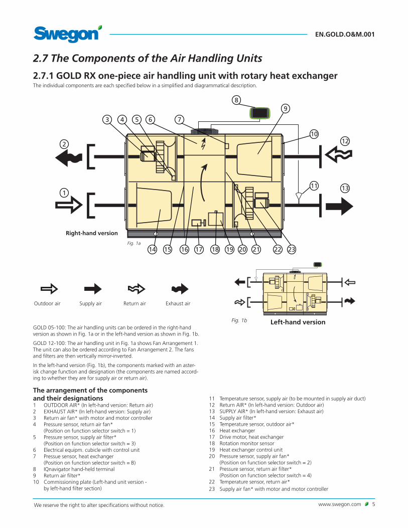
2.7.1 GOLD RX one-piece air handling unit with rotary heat exchangerThe individual components are each specified below in a simplified and diagrammatical description.
GOLD 05-100: The air handling units can be ordered in the right-hand version as shown in Fig. 1a or in the left-hand version as shown in Fig. 1b.
GOLD 12-100: The air handling unit in Fig. 1a shows Fan Arrangement 1. The unit can also be ordered according to Fan Arrangement 2. The fans and filters are then vertically mirror-inverted.
In the left-hand version (Fig. 1b), the components marked with an aster-isk change function and designation (the components are named accord-ing to whether they are for supply air or return air).
The arrangement of the components and their designations1 OUTDOOR AIR* (In left-hand version: Return air)2 EXHAUST AIR* (In left-hand version: Supply air)3 Return air fan* with motor and motor controller4 Pressure sensor, return air fan*
(Position on function selector switch = 1)5 Pressure sensor, supply air filter*
(Position on function selector switch = 3)6 Electrical equipm. cubicle with control unit7 Pressue sensor, heat exchanger
(Position on function selector switch = B)8 IQnavigator hand-held terminal9 Return air filter*10 Commissioning plate (Left-hand unit version -
by left-hand filter section)
11 Temperature sensor, supply air (to be mounted in supply air duct)12 Return AIR* (In left-hand version: Outdoor air)13 SUPPLY AIR* (In left-hand version: Exhaust air)14 Supply air filter*15 Temperature sensor, outdoor air*16 Heat exchanger17 Drive motor, heat exchanger18 Rotation monitor sensor19 Heat exchanger control unit20 Pressure sensor, supply air fan*
(Position on function selector switch = 2) 21 Pressure sensor, return air filter*
(Position on function selector switch = 4) 22 Temperature sensor, return air*23 Supply air fan* with motor and motor controller
Left-hand versionFig. 1b
Outdoor air Supply air Return air Exhaust air
Fig. 1a
Right-hand version
1
2
3 4 5 6
8
11
9
1012
13
15 16 17 18 19 20 21 22 2314
7
EN.GOLD.O&M.001
6 www.swegon.com We reserve the right to alter specifications without notice.
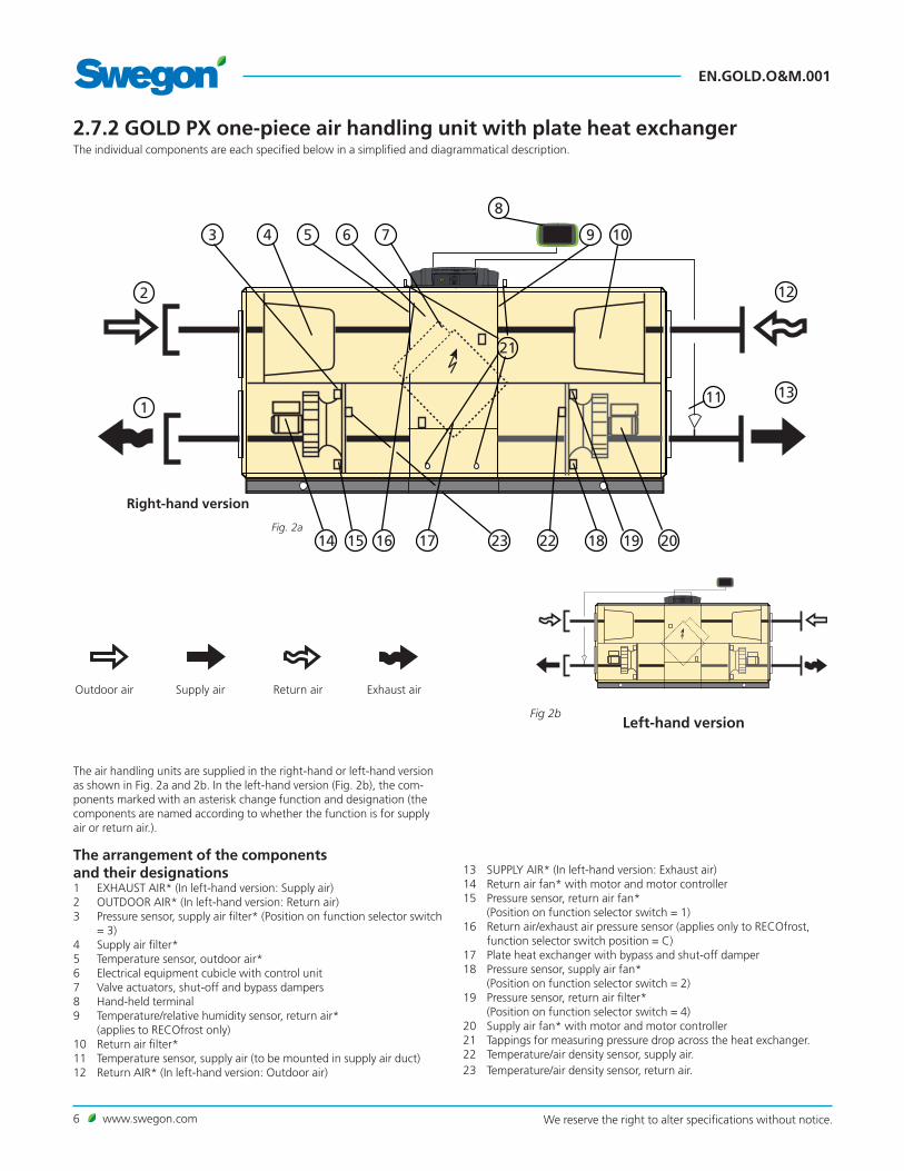
2.7.2 GOLD PX one-piece air handling unit with plate heat exchangerThe individual components are each specified below in a simplified and diagrammatical description.
Left-hand versionFig 2b
Outdoor air Supply air Return air Exhaust air
1
2
3 6
8
11
12
13
17 1918 2014
4
15
7 105 9
16
21
2223Fig. 2a
Right-hand version
The air handling units are supplied in the right-hand or left-hand version as shown in Fig. 2a and 2b. In the left-hand version (Fig. 2b), the com-ponents marked with an asterisk change function and designation (the components are named according to whether the function is for supply air or return air.).
The arrangement of the components and their designations1 EXHAUST AIR* (In left-hand version: Supply air)2 OUTDOOR AIR* (In left-hand version: Return air)3 Pressure sensor, supply air filter* (Position on function selector switch
= 3)4 Supply air filter*5 Temperature sensor, outdoor air*6 Electrical equipment cubicle with control unit7 Valve actuators, shut-off and bypass dampers8 Hand-held terminal9 Temperature/relative humidity sensor, return air*
(applies to RECOfrost only)10 Return air filter*11 Temperature sensor, supply air (to be mounted in supply air duct)12 Return AIR* (In left-hand version: Outdoor air)
13 SUPPLY AIR* (In left-hand version: Exhaust air)14 Return air fan* with motor and motor controller15 Pressure sensor, return air fan*
(Position on function selector switch = 1)16 Return air/exhaust air pressure sensor (applies only to RECOfrost,
function selector switch position = C)17 Plate heat exchanger with bypass and shut-off damper18 Pressure sensor, supply air fan*
(Position on function selector switch = 2)19 Pressure sensor, return air filter*
(Position on function selector switch = 4)20 Supply air fan* with motor and motor controller21 Tappings for measuring pressure drop across the heat exchanger.22 Temperature/air density sensor, supply air.23 Temperature/air density sensor, return air.

www.swegon.com 7We reserve the right to alter specifications without notice.
EN.GOLD.O&M.001
2.7.3 GOLD SD separate supply air and return air handling units, sizes 05-08The individual components are each specified below in a simplified and diagrammatical description.
Outdoor air Supply air
The air handling unit is supplied in the variant as shown in Fig. 4a. This variant can be positioned in several different ways as shown in Fig. 4b.
The air handling unit is shown here as a supply air handling unit. If the unit is used as an return air handling unit, the components marked with an asterisk change function and designation (the components are named according to whether the function is for supply air or return air).
The arrangement of the components and their designations1 OUTDOOR AIR*
(In return air handling units: Return air)2 Pressure sensor, supply air filter*, if applicable (Position on function
selector switch = 3) (In return air handling units: Pressure sensor, return air filter)
3 Temperature sensor, outdoor air/air density sensor, supply air* (In return air handling units: Temperature sensor, return air/air den-
sity sensor, exhaust air)4 Pressure sensor, supply air fan*
(Position on function selector switch = 2) (In return air handling units: Pressure sensor, return air fan)
5 Hand-held terminal6 Temperature sensor, supply air (to be mounted in supply air duct)
(Not used in return air handling units)7 SUPPLY AIR*
(In return air handling units: Exhaust air)8 Supply air fan* with motor and motor controller (In return air han-
dling units: Return air fan with motor and motor controller)9 Electrical equipment cubicle with control unit10 Supply air filter, if applicable*
(In return air handling units: Return air filter)
Fig. 4b
Fig. 4a
3
1
2 4
5
6 7
9 810
EN.GOLD.O&M.001
8 www.swegon.com We reserve the right to alter specifications without notice.
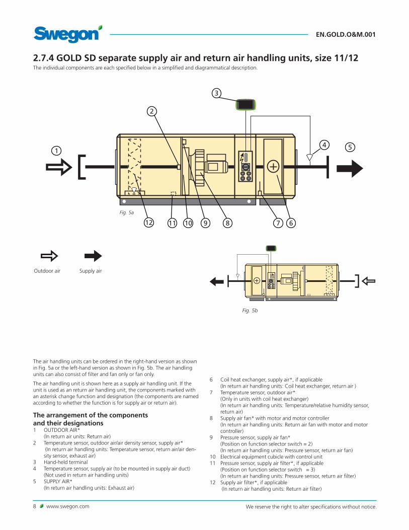
2.7.4 GOLD SD separate supply air and return air handling units, size 11/12The individual components are each specified below in a simplified and diagrammatical description.
The air handling units can be ordered in the right-hand version as shown in Fig. 5a or the left-hand version as shown in Fig. 5b. The air handling units can also consist of filter and fan only or fan only.
The air handling unit is shown here as a supply air handling unit. If the unit is used as an return air handling unit, the components marked with an asterisk change function and designation (the components are named according to whether the function is for supply air or return air).
The arrangement of the components and their designations1 OUTDOOR AIR* (In return air units: Return air)2 Temperature sensor, outdoor air/air density sensor, supply air*
(In return air handling units: Temperature sensor, return air/air den-sity sensor, exhaust air)
3 Hand-held terminal4 Temperature sensor, supply air (to be mounted in supply air duct)
(Not used in return air handling units)5 SUPPLY AIR*
(In return air handling units: Exhaust air)
6 Coil heat exchanger, supply air*, if applicable (In return air handling units: Coil heat exchanger, return air )
7 Temperature sensor, outdoor air* (Only in units with coil heat exchanger) (In return air handling units: Temperature/relative humidity sensor, return air)
8 Supply air fan* with motor and motor controller (In return air handling units: Return air fan with motor and motor controller)
9 Pressure sensor, supply air fan* (Position on function selector switch = 2) (In return air handling units: Pressure sensor, return air fan)
10 Electrical equipment cubicle with control unit11 Pressure sensor, supply air filter*, if applicable
(Position on function selector switch = 3) (In return air handling units: Pressure sensor, return air filter)
12 Supply air filter*, if applicable (In return air handling units: Return air filter)
Outdoor air Supply air
Fig. 5b
Fig. 5a
2
1
3
4 5
89 610 71112

www.swegon.com 9We reserve the right to alter specifications without notice.
EN.GOLD.O&M.001
The air handling units can be ordered in the right-hand version as shown in Fig. 6a or the left-hand version as shown in Fig. 6b. The air handling units can also consist of filter and fan only or fan only.
The air handling unit is shown here as a supply air handling unit. If the unit is used as an return air handling unit, the components marked with an asterisk change function and designation (the components are named according to whether the function is for supply air or return air).
The arrangement of the components and their designations1 OUTDOOR AIR*
(In return air handling units: Return air)2 Temperature sensor, outdoor air/air density sensor, supply air*
(In return air handling units: Temperature sensor, return air/air den-sity sensor, exhaust air)
3 Hand-held terminal4 Temperature sensor, supply air (to be mounted in supply air duct)
(Not used in return air handling units)5 SUPPLY AIR*
(In return air handling units: Exhaust air)
6 Supply air fan* with motor and motor controller (In return air handling units: Return air fan with motor and motor controller)
7 Pressure sensor, supply air fan* (Position on function selector switch = 2) (In return air handling units: Pressure sensor, return air fan)
8 Electrical equipment cubicle with control unit9 Coil heat exchanger, supply air*, if applicable
(In return air handling units: Coil heat exchanger, return air )10 Temperature sensor, outdoor air*
(Only in units with coil heat exchanger) (In return air handling units: Temperature/relative humidity sensor, return air)
11 Pressure sensor, supply air filter* (Position on function selector switch = 3) (In return air units: Pressure sensor, return air filter)
12 Supply air filter*, if applicable (In return air handling units: Return air filter)
2.7.5 GOLD SD separate supply air and return air handling units, Sizes 14-100, with coil heat exchangersThe individual components are each specified below in a simplified and diagrammatical description.
Outdoor air Supply air
Fig. 6a
2
1
3
4 5
679 8101112
Fig. 6b

EN.GOLD.O&M.001
10 www.swegon.com We reserve the right to alter specifications without notice.
3. Commissioning
3.1 GeneralCommissioning sequence:
1. Remove the air handling unit’s protective plastic foil.
2. Check that there are no foreign objects inside the unit, duct system or functional sections.
3. Check that rotary heat exchanger rotor (only GOLD RX) rotates easily. On sizes 50-100, the rotary heat exchanger must be angled slightly towards the filter, see drawing below.
If the inclination needs adjusting, see special instructions for adjust-ing the inclination of the rotary heat exchanger (05-80).
GOLD RX, sizes 50-100: The illustration shows the factory-preset ro-tor inclination for Fan Arrangement 1. The inclination must always be toward the filter, which means that the inclination for Fan Arrangement
2 is in the other direction.
4. Turn the safety isolating switch to the ON position (I).
5. Select the appropriate language, if you have not already done so. See Section 5.3.7 or 6.4.7.
6. The air handling unit has a factory setting that makes it ready to oper-ate. See Section 11.2 Commissioning Report.
However, in many cases, these settings need to be adjusted to suit the current installation.
If necessary, enter the fan position setting (inspection side), see Sec-tion 6.4.10.
Program the timer (switch clock), operating mode, temperatures, airflows and functions according to the procedures in Sections 4-15.
Select whether the airflow unit of measurement shall be l/s, m3/s, m3/h or cfm.
Fill out the Commissioning Record and save it in the document pocket of the air handling unit.
In some cases it might be necessary to adjust the P-band and the I-time if the heating regulation system is oscillating or operates slug-gishly. This requires entering a special code. Contact your Swegon representative.
7. Activate, if needed, manual or auto operation (Dashboard) or lock the speed of the fans (AIRFLOW ADJUSTMENT image). Adjust the airflow in the duct system and air terminals as described in Section 3.2.
8. Check and adjust, if required, the pressure balance in the air handling unit as described in Section 3.3.
9. Finish off with a filter calibration as described in Section 6.3.
L
L
≈ 0,5xL
≈ 0,5xL

www.swegon.com 11We reserve the right to alter specifications without notice.
EN.GOLD.O&M.001
3.3 To Adjust the Pressure Balance Applicable to air handling units with rotary heat exchanger only.
OPEN(Remove commissioning plates)
CLOSE(Insert one or more
commissioning plates)
Commissioning plates
3.3.1 GeneralThere should be a certain degree of negative pressure in the return air section so that the direction of air leakage through the heat exchanger and the function of the purging sector will be correct. This ensures that return air will not be transferred to the supply air.
The pressure balance in the unit should be adjusted when the ventilation system has been fully installed and the airflows discharged from all the air diffusers and registers have been adjusted, and when the supply air and return airflows are as they should be while the air handling unit is operat-ing normally.GOLD RX
Air intake viewed from the side
Sizes 05 – 12, 1 – 2 plates Sizes 14 – 100, 1 – 5 platesAir intake viewed from above
Sizes 14 – 30, 2 plates
Secure the commissioning plates to the ceiling with self-tapping screws from inside the AHU.
Adjust the pressure balance by blanking off the holes in the commissioning plate using the plastic plugs supplied with it (reach up and insert plastic plug through the rectangular hole in the commissioning plate).

EN.GOLD.O&M.001
12 www.swegon.com We reserve the right to alter specifications without notice.
3.3.2. Ensure correct direction of air leakageThe commissioning plates fitted in the return air inlet are used for adjusting the pressure balance in the unit. The commissioning plates are supplied separately and should be fitted in the unit by the fitter when he connects the return air ducting to the air handling unit. See the illustra-tions on the following pages.
Connect a pressure gauge to the pressure measurement tappings of the air handling unit. The unit has four pressure measurement tappings. The two tappings closest to the return air duct should be used. The blue pres-sure measurement tapping is used for measuring the negative pressure in the return air section and the white pressure measurement tapping is used for measuring the negative pressure in the supply air section.
On the size 05-08 units, the pressure measurement tappings are in the electrical equipment cubicle/electrical distribution box and on the size 11-100 units they are inside in the centre section of the unit.
Note that both pressure measurement tappings are used for measuring negative pressure.
MEASURED VALUES
The negative pressure in the return air section should be higher or the same as the negative pressure in the supply air section.
If the negative pressure in the return air section is the same or up to 0.08 in. WG. greater than the negative pressure in the supply air section, then you’ve finished this adjustment.
DeviationsIf the negative pressure in the return air section is less than that in the supply air section, the damper setting must be adjusted as follows:
1. Stop the air handling unit, open the inspection door to access the return air filter. GOLD RX with air intake from above: Blank off an appropriate number of holes in the commissioning plate using the plastic plugs supplied.
GOLD RX with air intake from the side: Slightly push the commission-ing plates forward (close them) in the return air intake. For full face connection (duct accessory in insulated casing): If the commissioning plate(s) is/are completely closed and the sub-atmo-spheric pressure in the return air section is still less than in the supply air section, blank off an appropriate number of holes in the commis-sioning plate using the plastic plugs supplied.
3. Close the inspection door and restart the unit.
4. Measure the pressures.
Repeat this procedure until the negative pressure in the return air section is just as high or up to 0.08 in. WG higher than the negative pressure in the supply air section (0–0.08 in. WG).
5. If the negative pressure in the return air section is higher than 0.08 in. WG. compared with the supply air section, although the commis-sioning plates are completely open, the leakage and purging air flow will be more than necessary, and this will cause the return air fan to consume more power.
Pressure measurement tappings, direction of air leakage (Right-hand air handling unit)
- (blue) + (white)
GOLD 05-08
GOLD 11-80
– (blue)
+ (white)
Return AIR
Return AIR
GOLD 100
– (blue)
+ (white)
Return AIR

www.swegon.com 13We reserve the right to alter specifications without notice.
EN.GOLD.O&M.001
4. IQnavigator Hand-held Terminal and Image Management
4.1 IQnavigator Hand-held Terminal
4.1.1 GeneralThe hand-held terminal consists of a 7” capacitive touch screen with a 3 metre long cable for connection to the air handling unit's control circuit card by means of a quick-fit connector.
The hand-held terminal is switched on/off with an on/off button located on the top side of the terminal. If the hand-held terminal is not used for 45 minutes, it switches over to the sleep mode.
See the illustrations below for particulars of the connections, buttons and LEDs.
IQnavigator can be used outdoors, but it must be kept at a weatherproof place.
N.B.! When you disconnect the cable from IQnavigator, squeeze the connector so that you press in the catch inside the connec-tor (hidden under the protective rubber covering).
Alarm indicating LED Flashes red in event of an alarm
In operation indicating LED Green steady glow while unit is operating
Light sensor
SD card for future function
USB connection for future function Connection for
external power supply (accessory)
Headphone connection For future function
Data:Operating temperature: -4 – 120°F (-20 – 50°C)Height from which it can be dropped without damage: 3 feet
On/off button:
When the touch screen is at rest or is switched off: Brief press of the On/Off button = touch screen awakens or starts up
When the touch screen is on: Brief press of the On/Off button = touch screen at rest
Long press of the On/Off button = Question, "Do you want to power off IQnavigator?" is displayed, press OK, touch screen switches off
RJ45 connection for power and com-munication cable for IQnavigator (PoE) or
connection to the network (requires a ABLZ-1-70 net adapter accessory)
RJ12 contact for future function
EN.GOLD.O&M.001
14 www.swegon.com We reserve the right to alter specifications without notice.
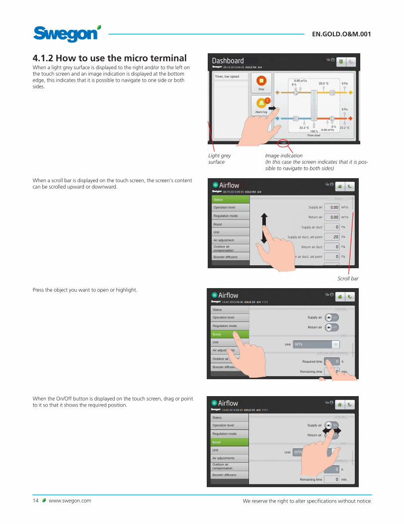
4.1.2 How to use the micro terminal
Airflow
Status
Regulation mode
Boost
Unit
Air adjustments
Outdoor air compensation
Booster diffusers
Operation level Supply air
Return air
Unit
Remaining time
Required time h
min.
FORCING
UNIT
AIRFLOW ADJUSTMENTS
When a scroll bar is displayed on the touch screen, the screen's content can be scrolled upward or downward.
Scroll bar
When a light grey surface is displayed to the right and/or to the left on the touch screen and an image indication is displayed at the bottom edge, this indicates that it is possible to navigate to one side or both sides.
Light grey surface
Image indication (In this case the screen indicates that it is pos-sible to navigate to both sides)
Dashboard
Stop
Alarm log
Timer, low speed
Flow chart
Airflow
Supply air
Return air
Supply air duct
Supply air duct, set point
Return air duct
Return air duct, set point
Status
Regulation mode
Boost
Unit
Air adjustment
Outdoor air compensation
Booster diffusers
Operation level
Status
When the On/Off button is displayed on the touch screen, drag or point to it so that it shows the required position.
Press the object you want to open or highlight.
Airflow
Status
Regulation mode
Boost
Unit
Air adjustments
Outdoor air compensation
Booster diffusers
Operation level Supply air
Return air
Unit
Remaining time
Required time h
min.
FORCING
UNIT
AIRFLOW ADJUSTMENTS

www.swegon.com 15We reserve the right to alter specifications without notice.
EN.GOLD.O&M.001
Dashboard
Stop
Alarm log
Timer, low speed
Flow chart
4.1.3 ButtonsButtons along the upper edge of the touch screen have the following functions:
Press this button to log out.
Press this button to go one step upward in the image tree.
Press this button to close a window and to return to a previously displayed object.
Press this button to return to the dashboard.
Help texts for the current view.
4.1.4 Indicator symbols
Hand-held terminal connected.
The hand-held terminal has no connection.
Not logged on
Logged on user (local)
Logged on installation
Indicates that the web page is active
Indicates that some communication protocol is activated
The current time/date, type of air handling unit and the name of the plant are displayed along the upper edge of the touch screen. See also Section 6.4.10.1.
Dashboard
Stop
Alarm log
Timer, low speed
Flow chartLog graph
Log graph

EN.GOLD.O&M.001
16 www.swegon.com We reserve the right to alter specifications without notice.
4.1.5 KeyboardThe value that can be changed is highlighted in grey. A keyboard is dis-played at the lower edge of the touch screen when you log on and enter settings.
A value you want to change can be highlighted by pressing it on the touch screen.
Then enter the required value and save it by pressing on the Done button.
The function of the buttons:
Decimal point
Deletes previous character
Decreases the highlighted value
Increases the highlighted value
Minus sign. Used for writing negative values.
Unspecified value. Used for the time and schedule function.
User selection
Enter PIN code
Cancel Done
www.swegon.com 17We reserve the right to alter specifications without notice.
EN.GOLD.O&M.001
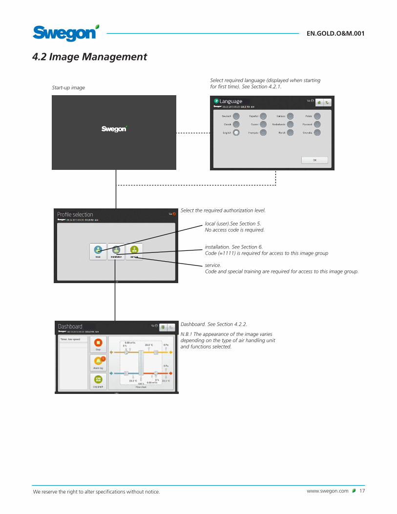
4.2 Image Management
Start-up image Select required language (displayed when starting for first time). See Section 4.2.1.
Dashboard. See Section 4.2.2.
N.B.! The appearance of the image varies depending on the type of air handling unit and functions selected.
Select the required authorization level.
local (user).See Section 5. No access code is required.
installation. See Section 6. Code (=1111) is required for access to this image group
service. Code and special training are required for access to this image group.
Profile selection
Dashboard
Stop
Alarm log
Timer, low speed
Flow chartLog graph

EN.GOLD.O&M.001
18 www.swegon.com We reserve the right to alter specifications without notice.
Dashboard
Stop
Alarm log
Timer, low speed
Flow chart
4.2.1 Selection of languageWhen the air handling unit starts up for the first time, a language selec-tion image is displayed. Select required language and press OK.
If you want to change to a different language later on – or if you’ve selected the wrong language – you can change the language under Func-tions in the hand-held terminal. See Section 5.3.7.
4.2.2 Dashboard
4.2.2.1 GeneralThe dashboard is normally displayed if no other image has been selected.
The touch screen switches to the sleep mode after 45 minutes. To leave the sleep mode, press on the touch screen's On/Off button.
The content in the flow chart changes depending on the selected type of air handling unit and other functions that affect the relevant operating conditions.
4.2.2.2 To change the operating modeYou can start and stop the air handling unit or change over to manual or automatic operation from the dashboard.
The air handling unit should normally be started and stopped from the hand-held terminal; not by switching the safety isolat-ing switch on and off.
4.2.2.3 Alarm logActive alarms, pending alarms and alarm history (50 latest) can be viewed under Alarm log. See also Section 8.
Shows number of cur-rent alarms
Shows current operation status
Log graph

www.swegon.com 19We reserve the right to alter specifications without notice.
EN.GOLD.O&M.001
4.2.2.4 Log diagramAn SD card must be fitted into the air handling unit's control circuit card (installed from the factory) in order to make this function possible. Does not apply to the real time log.
Under "Log diagram", a number of signals can be read in diagram form. Up to four signals can be freely selected and read in the list under the "Signals" button. The log diagram's time interval can be selected as fol-lows: 4 hours, day, week, month or year.
In the list under the "Signals" button, you can also choose to mark one of the signals to display it with a thicker line in the log diagram. This is done by tapping the desired coloured square.
The program automatically adjusts the resolution of the signals. The means that the program adapts the amplitude of the signal to the height of the diagram within the selected time interval.
The Log diagram can be selected in two types: History or Real time, under the "Mode" button.
The cursor of the diagram is fixed and the time line can be moved by scrolling to the right or to the left.
4.2.2.5 Flow chartThe flow chart can be displayed in full screen by tapping the Flow chart heading.
Setting the Edit button to ON makes the flow chart editable.
The positions of all the components marked with a green frame are interchangeable, for example the mutual order between the air heater and the air cooler. Place your finger on the relevant component, drag it to the desired position and lift your finger. The circulation pump of the air heater can be hidden by clicking on the air heater symbol.
The grey-marked components with green frame are inactive. These can be activated by tapping the desired component.
Flow chart
Edit
Edit button Component with green frame
Signals button Time intervals
Example of coloured square
Mode button
Log graph
Cursor
Signals Position 4 hours Day Week MonthYear
Summation, outdoor air regulation
Outdoor air
Add signal

EN.GOLD.O&M.001
20 www.swegon.com We reserve the right to alter specifications without notice.
Profile selection
Guides
5. User (local)
5.1 Image ManagementIf the touch screen is at rest, press the hand-held terminal's On/Off button.
Profile selection. Press on local (user). Does not require entering a code
Filter calibration. See Section 5.2
Dashboard. See Section 4.2.2
Functions. See Section 5.3
Filtercalibration
Dashboard
Stop
Alarm log
Timer, low speed
Flow chart
Functions
Airflow Temperature Filters Software
Language
Time and schedule
Energy monitoring
Log graph
www.swegon.com 21We reserve the right to alter specifications without notice.
EN.GOLD.O&M.001
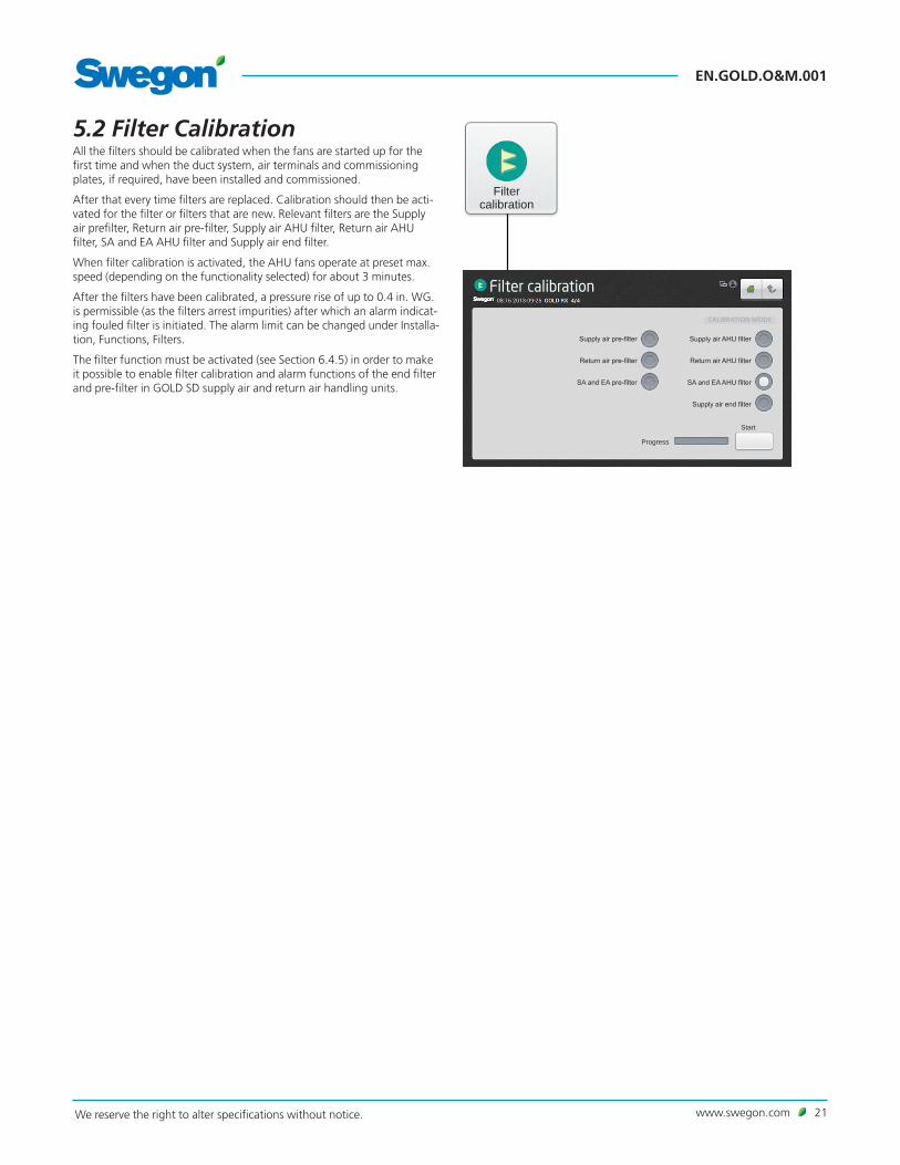
5.2 Filter CalibrationAll the filters should be calibrated when the fans are started up for the first time and when the duct system, air terminals and commissioning plates, if required, have been installed and commissioned.
After that every time filters are replaced. Calibration should then be acti-vated for the filter or filters that are new. Relevant filters are the Supply air prefilter, Return air pre-filter, Supply air AHU filter, Return air AHU filter, SA and EA AHU filter and Supply air end filter.
When filter calibration is activated, the AHU fans operate at preset max. speed (depending on the functionality selected) for about 3 minutes.
After the filters have been calibrated, a pressure rise of up to 0.4 in. WG. is permissible (as the filters arrest impurities) after which an alarm indicat-ing fouled filter is initiated. The alarm limit can be changed under Installa-tion, Functions, Filters.
The filter function must be activated (see Section 6.4.5) in order to make it possible to enable filter calibration and alarm functions of the end filter and pre-filter in GOLD SD supply air and return air handling units.
Filter calibration
Filter calibration
Supply air pre-filter
Return air pre-filter
SA and EA pre-filter
Supply air AHU filter
Return air AHU filter
SA and EA AHU filter
Supply air end filter
Progress
Start
CALIBRATION MODE

EN.GOLD.O&M.001
22 www.swegon.com We reserve the right to alter specifications without notice.
5.3.1 AirflowSee also Section 6.4.1 in which the functions for airflow described in detail.
5.3.1.1 StatusAll the relevant values can be read here. Used for performance checks.
5.3.1.2 Operation levelThe functions selected (under Installation) and the min. and max. airflows of each AHU size (see the table below) determine which values can be set.
Values for airflow (l/s, m3/s, m3/h, cfm), pressure (Pa, psi, in. wc.) or input signal strength (%) can be preset depending on the function selected.
Low speedShould always be preset. The value for low speed cannot be higher than the value for high speed. Low speed can be set to 0, which means that the AHU is idle.
High SpeedShould always be preset. The value or pressure for high speed cannot be lower than the value for low speed.
Max. speedShould always be preset. Used mainly for filter calibration. While filter calibration is in progress, the max. speed setting should be as high as the ventilation system permits without causing any breakdown. Also used for the pressure regulation, forcing, Heating Boost and Cooling Boost functions. The value for max speed cannot be lower than the value for high speed.
5.3 Functions
Airflow
Status
Operation level
Air adjustment
Min. /Max. speedUsed for the demand control function (the previous section also applies to max. speed). Preset the lowest and highest permissible flows for each fan. This means that the fans will not operate outside these limits, regard-less the load.
5.3.1.3 Air adjustmentThe speed of the fans can be locked for up to 72 hours. When the func-tion is activated, the speed is locked at the current speed of operation. This is practical when making airflow adjustments in the duct system and air terminals. The desired period is preset, but can be interrupted earlier by selecting Stop or by changing the time setting to 0.
Min./Max. flows
1) When adjusting the flow, round off the value to the nearest settable step.2) If pressure regulation is used, the airflow can be regulated to zero, however this presupposes a certain static pressure drop in the ducting (approx. 0.2 in. WG).
AIRFLOW MIN. FLOW FOR AIRFLOW REG., ALL VARIANTS2
MAX. FLOW, ONE-PIECE AHU
ROTARY HEAT EXCH. (RX)
MAX. FLOW, ONE-PIECE AHU PLATE H. EXCH.
(PX)
MAX. FLOW, SA AND EA AHU’S
(SD)
SMALLEST STEP
SIZE CFM L/s CFM L/s CFM L/s CFM L/s CFM L/s
GOLD 05 170 80 1377 650 1377 650 1695 800 15 7
GOLD 07 170 80 1589 750 1589 750 1695 800 15 7
GOLD 08 424 200 2119 1000 2119 1000 2543 1200 15 7
GOLD 11 424 200 2331 1100 2331 1100 2543 1200 15 7
GOLD 12 424 200 2967 1400 2967 1400 3814 1800 15 7
GOLD 14 424 200 3496 1650 3496 1650 3814 1800 15 7
GOLD 20 636 300 4450 2100 4450 2100 5933 2800 15 7
GOLD 25 636 300 5298 2500 5298 2500 5933 2800 15 7
GOLD 30 1060 500 6781 3200 6781 3200 8476 4000 15 7
GOLD 35 1060 500 8264 3900 8476 4000 59 28
GOLD 40 1589 750 10595 5000 12714 6000 59 28
GOLD 50 1271 600 10595 5000 12714 6000 59 28
GOLD 60 2119 1000 13774 6500 16952 8000 59 28
GOLD 70 2119 1000 15893 7500 16952 8000 59 28
GOLD 80 3179 1500 20131 9500 25428 12000 59 28
GOLD 100 3179 1500 23309 11000 25428 12000 59 28

www.swegon.com 23We reserve the right to alter specifications without notice.
EN.GOLD.O&M.001
5.3.2 TemperatureBasic functions can be set under Installation and the values can be read and set under User (local).
Therefore see also Section 6.4.2 in which the functions for tem-perature are described in detail.
N.B.! If the entry of new temperature settings involve large changes, you should first stop the AHU before you enter the new settings.
Specific temperatures, such as set points, should be specified in °C or °F, whereas displacements, deviations and differentials should be specified in K (Kelvin).
If only GOLD SD supply air handling units are installed, they require an external room sensor for ERS, ORE and return air regulation.
5.3.2.1 StatusAll the relevant values can be read here. Used for performance checks.
5.3.2.2 Settings
ERS Regulation 1The control unit regulates the ratio between the supply air and return air temperature according to a factory-preset curve.
Settings (see also diagram to the right):
Value Setting range
Factory setting
Return related supply air-1 step 1 – 4 2Return related supply air-1 diff 1– 7 K 3 KReturn related supply air-1 breakpoint (refers to return air temperature)
54 – 79°F 72°F
ERS Regulation 2An individually adjusted curve regulates the ratio between the supply air and the return air temperature. The curve has four adjustable break-points.
Settings (see also diagram to the right):
Value Setting range
Factory setting
Return air temperature
Return related supply air-2 X1 50 – 104°F 59°FReturn related supply air-2 X2 50 – 104°F 68°F
Return related supply air-2 X3 50 – 104°F 72°F
Return related supply air-2 X4 50 – 104°F 72°F
Supply air temperature set pointReturn related supply air-2 Y1 50 – 104°F 68°F
Return related supply air-2 Y2 50 – 104°F 64°F
Return related supply air-2 Y3 50 –104°F 57°F
Return related supply air-2 Y4 50 –104°F 54°F
Temperature
Settings
Status
15
10
20
12 15 20 25
Return air temperature °F
Sup
ply
air
tem
per
atu
re s
et p
oin
t °
F Step 1
Step 2Breakpoint
ERS 1
diff
.Step 3
Step 4
1
2
3
4
15
20
22
9
10
12 15 20 25 27
X = Return air temperature °F
Y =
Su
pp
ly a
ir t
emp
erat
ure
set
po
int
°F
ERS Regulation 2, example
68
68
72
68
68
77
77 81
59
59
50
50
48
54
54
59
59

EN.GOLD.O&M.001
24 www.swegon.com We reserve the right to alter specifications without notice.
Supply air regulationSupply air regulation involves maintaining a constant supply air tempera-ture without consideration to the load in the premises.
Settings:
Value Setting range
Factory setting
Supply air (temp. set point) 32 – 104°F 70°F
Return air regulationReturn air regulation involves maintaining a constant temperature in the return air duct (the premises), by regulating the supply air temperature.
Settings:
Value Setting range
Factory setting
Return air (temp. set point) 32 – 104°F 70°F
Supply air, min. 32 – 68°F 59°F
Supply air, max. 61 – 122°F 82°F
ORS regulation An individually adjusted curve regulates the ratio between the outdoor air and the supply air temperature. The curve has four adjustable break-points.
Settings (see also diagram to the right):
Value Setting range
Factory setting
Outdoor air temperature
Outdoor related supply air X1 -58 – 122°F -4°FOutdoor related supply air X2 -58 – 122°F 14°FOutdoor related supply air X3 -58 – 122°F 50°FOutdoor related supply air X4 -58 – 122°F 68°FSupply air temperature set pointOutdoor related supply air Y1 50°F 71°FOutdoor related supply air Y2 50°F 71°FOutdoor related supply air Y3 50°F 71°FOutdoor related supply air Y4 50°F 71°F
ORE regulation An individually adjusted curve regulates the ratio between the outdoor air and the return air temperature. The curve has four adjustable break-points.
Settings (see also diagram to the right):
Value Setting range
Factory setting
Supply air, min. 32 – 68°F 60.8°F
Supply air, max. 32 –112°F 82.4°F
Outdoor air temperature
Outdoor related return air X1 -58 – 122°F -4°FOutdoor related return air X2 -58 – 122°F 14°FOutdoor related return air X3 -58 – 122°F 50°FOutdoor related return air X4 -58 – 122°F 68°FReturn air temperature set pointOutdoor related return air Y1 50°F 71°FOutdoor related return air Y2 50°F 71°FOutdoor related return air Y3 50°F 71°FOutdoor related return air Y4 50°F 71°F
X = Outdoor air temperature °F
Y =
Ret
urn
air
tem
per
atu
re s
et p
oin
t °
F
ORE regulation, example
X = Outdoor air temperature °F
Y =
Su
pp
ly a
ir t
emp
erat
ure
set
po
int
°F
ORS regulation, example
1
2 3
4
15
20
25
-30 -20 -10 0 +30+20+10
1
2 3
4
15
20
25
-30 -20 -10 0 +30+20+10
77
77
68
68
59
59
–30
–30
–4
–4
14
14
32
32
50
50
68
68
86
86

www.swegon.com 25We reserve the right to alter specifications without notice.
EN.GOLD.O&M.001
5.3.2.3 Regulation ModeThe temperature, at which seasonal controlled temperature regulation shall be enabled and disabled respectively, can be preset.
Settings:
If only GOLD SD supply air handling units are installed, they require an external room sensor for ERS, ORE and return air regulation.
Value Setting range
Factory setting
Seasonal controlled temperature regulation, enabled Seasonal controlled temperature regulation, disabled
-4 – 104°F
-4 – 104°F
32°F
32°F

EN.GOLD.O&M.001
26 www.swegon.com We reserve the right to alter specifications without notice.
5.3.3 Time and scheduleThe built-in timer enables you to control the AHU's operating mode/time. Certain other oversteering functions such as external timer, communica-tion, etc. affect the preset operating modes.
There are five different operating modes: Total stop = The AHU is completely stopped, no internal automatic func-tions or external control commands can start the AHU. Total stop also oversteers manual operation via the hand-held terminal.
Low speed = The AHU is running at the preset low speed setting. High speed = The AHU is running at the preset high speed setting. Normal Stop = The AHU has stopped, however all the internal and exter-nal automatic functions oversteer the stop. Extended Normal Stop = The AHU has stopped, however all the internal and external automatic functions, with exception of Summer night cool, oversteer the stop.
5.3.3.1 Time and dateThe current date and time can be set and adjusted if needed. The timer automatically takes leap years into consideration.
The relevant region and city can be selected, summer time/winter time change-over will then be managed automatically.
Time source can be set to manual or via SNTP (requires connection to
network) and BACnet. The time format and date format can be set.
5.3.3.2 Schedule settingsThe relevant operating mode can be read under Schedule settings. Here you can also set a preselected operating mode, in which the air handling unit always operates during non-programmed time, under Day schedule and Exceptions schedule. This setting (start and stop date not activated) is used most often and covers the majority of needs.
When the start and stop date is activated, this means that during the preset period (date) preset time applies during the day schedule and the exceptions schedule, and at all other times the AHU runs in the prese-lected operating mode.
Settings:
Value Setting range
Factory settings
Preselected operating mode Total stop/Low speed/High speed/Normal Stop/ Extended Normal Stop
Low speed
Start date Active/Inactive InactiveStart date Year/Month/DayStop date Active/Inactive InactiveStop date Year/Month/Day
Time and schedule
Time and date
Schedule settings

www.swegon.com 27We reserve the right to alter specifications without notice.
EN.GOLD.O&M.001
Day schedule5.3.3.3 Day scheduleTimes and days can be set when the air handling unit is to run in the high speed mode, low speed mode or be switched off.
For each day (Monday - Sunday), six different events can be set to occur at a given point in time. Here, it is also possible to set six different events for two exceptions under Ex1 and Ex2. The provisions for these excep-tions can then be set under Exceptions schedule, Calendar 1 and Calen-dar 2.
Note that the preset event will not be carried over to the next 24-hour period. If no event is set from 00.00 hours of the next 24-hour period, the AHU will operate in the preselected operating mode preset under Schedule settings.
Settings:
Value Setting range
Factory settings
Day Mon/Tues/Wed/Thurs/Fri/Sat/Sun/Ex1/Ex2Time 00:00-23:59 00:00Action Inactive/Total stop/Low speed/High speed/
Normal Stop/ Extended Normal Stop/Ignore
Inactive
5.3.3.4 Exceptions schedulePossible exceptions (Ex1 and Ex2), previously preset in the day schedule can be set in the Exceptions schedule. Here you can determine on which date or weekday the relevant exception shall apply. If you select Calendar 1 or Calendar 2, which is the most often the case, these can be set ac-cording to particulars in the next section.
Settings:
Value Setting range
Factory settings
Exceptions schedule 1/2Exceptions method Inactive/Date/Date
range/Weekday/Calendar 1/Calendar 2
Calendar 1/2
DateStart date Year/Month/DayStart weekday Each day/Monday/
Tuesday/Wednesday/Thursday/Friday/Saturday/Sunday
Each day
Date rangeStart date Year/Month/DayStart weekday Each day/Monday/
Tuesday/Wednesday/Thursday/Friday/Saturday/Sunday
Each day
Stop date Year/Month/DayStop weekday Each day/Monday/
Tuesday/Wednesday/Thursday/Friday/Saturday/Sunday
Each day
WeekdayStart date Mon 1-12/Odd/Even/
Each Day 1-7/8-14/15-21/22-28/29-31/Latest 7 days/Each day
Start weekday Each day/Monday/Tuesday/Wednesday/Thursday/Friday/ saturday/Sunday
Each day
Calender 1 See next chapterCalender 2 See next chapter
Exceptions schedule

EN.GOLD.O&M.001
28 www.swegon.com We reserve the right to alter specifications without notice.
Calendar 15.3.3.5 Calendar 1 and 2The specific days when Exceptions schedule 1 or 2 shall apply can be set in Calendars 1 and 2. On condition that Calendar 1 or 2 is selected, see previous section. In other cases, these settings will have no effect.
There is a total of ten possible settings under each calendar and various functions can be selected for each.
Settings (For Calendar 1 and Calendar 2 respectively):
Value Setting range
Factory setting
Function 1-10 Inactive/Date/Date range/Weekday InactiveDateStart date Year/Month/DayStart weekday Each day/Monday/Tuesday/
Wednesday/Thursday/Friday/Saturday/Sunday
Each day
Date rangeStart date Year/Month/DayStop date Year/Month/DayWeekdayStart date Month 1-12/Odd/Even/Each
Day 1-7/8-14/15-21/22-28/29-31/Latest 7 days/Each day
Start weekday Each day/Monday/Tuesday/Wednesday/Thursday/Friday/Saturday/Sunday
Each day
5.3.3.6 Prolonged operationThe control unit inputs for external low speed (terminals 14-15) and external high speed (terminals 16-17) respectively, can be supplemented with prolonged operation. They can be used for overtime running acti-vated by a push button, for example.
The required time in hours and minutes can be set as follows.
Settings:
Value Setting range
Factory setting
Ext. low speed 0:00 - 23:59 0:00 Ext. high speed 0:00 - 23:59
(hrs.:min.)0:00 (hrs.:min.)
Calendar 2
Prolonged operation

www.swegon.com 29We reserve the right to alter specifications without notice.
EN.GOLD.O&M.001
5.3.4 Energy monitoringStatus of the power consumed by fans and other AHU components can be viewed here. SFP status for the AHU fans and the efficiency on heat transfer of the rotary heat exchanger can also be viewed.
Energy monitoring
5.3.5 FiltersBasic functions can be set under Installation and the values can be read and set under User (local).
The filter status and the current alarm limit status for filters with activated monitoring can be viewed here. Relevant filters are the Supply air prefil-ter, Return air pre-filter, Supply air AHU filter, Return air AHU filter, SA and EA AHU filter and Supply air end filter.
Filter calibration can be manually activated for each filter. For more detailed information, see Section 5.2.
Filters
5.3.6 SoftwareThe relevant program versions for the IQlogic control unit, IQnaviga-tor hand-held terminal and input units on the communication bus can be viewed and updated from the SD circuit card inserted in the IQlogic control unit (this can take a few minutes). Software
5.3.7 LanguageThe language desired can be set here. The appropriate language is nor-mally selected the first time the AHU is started up. However, the language setting can be changed at any time.
Settings:
Value Setting range
Factory setting
Language Available languages are displayed
English
Language
EN.GOLD.O&M.001
30 www.swegon.com We reserve the right to alter specifications without notice.
Functions
Air flow Temperature Filters Software
Language
Time and schedule
Energy monitoring
Alarm prioritys
Air handling unit
Heat Cool
SMART Link Air humidity ReCO2
All Year Comfort
Log
MIRU Control
Profile selection
6. Installation
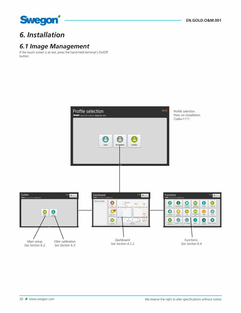
6.1 Image ManagementIf the touch screen is at rest, press the hand-held terminal's On/Off button.
Profile selection. Press on installation. Code=1111.
Filter calibration. See Section 6.3.
Dashboard. See Section 4.2.2.
Functions. See Section 6.4
Main setup. See Section 6.2.
Guides
Filtercalibration
Dashboard
Stop
Alarm log
Timer, low speed
Flow chart
Main setup
Log graphHeat/Cool recovery

www.swegon.com 31We reserve the right to alter specifications without notice.
EN.GOLD.O&M.001
6.2 Main SetupMain setup can be selected when installing the AHU and is an aid for configuring and starting up the AHU.
Time and date, air flow unit, airflow regulation mode, airflow operation level, temperature regulation, temperature settings and fan position set-tings can be entered here.
For mosre detailed information, see the relevant function below.
Main setup
6.3 Filter CalibrationAll the filters should be calibrated when the fans are started up for the first time and when the duct system, air terminals and commissioning plates, if required, have been installed and commissioned.
After that every time filters are replaced. Calibration should then be activated for the filter or filters that are new. Relevant filters are the Supply air prefilter, Return air pre-filter, Supply air AHU filter, Return air AHU filter, SA and EA AHU filter and Supply air end filter.
When filter calibration is activated, the air handling unit runs at the preset max. speed (depending on the functionality selected) for about 70 seconds.
After the filters have been calibrated, a pressure rise of up to 100 Pa is permissible (as the filters arrest impurities) after which an alarm indicating fouled filter is initiated. The alarm limit can be changed under Installation, Functions, Filters.
The filter function must be activated (see Section 6.4.5) in order to make it possible to enable filter calibration and alarm functions of the end filter and pre-filter in GOLD SD supply air and return air handling units.
See Section 6.4.3.1
See Section 6.4.1.3
See Section 6.4.1.2
See Section 6.4.2.3
See Section 6.4.2.2
See Section 6.4.10.1
Main setup
1 Time and date
Time2 Air flow unit
3 Air flow regulation mode
4 Air flow operation level
5 Temperature regulation
6 Temperature settings
7 Fan position
8 Finish
TIME AND DATE
Date
Weekday
Time zone
Wednesday
Filter calibration
Filter calibration
Supply air pre-filter
Return air pre-filter
SA and EA pre-filter
Supply air AHU filter
Return air AHU filter
SA and EA AHU filter
Supply air end filter
Progress
Start
CALIBRATION MODE
See Sections 6.4.1.6 and 6.4.2.4

EN.GOLD.O&M.001
32 www.swegon.com We reserve the right to alter specifications without notice.
6.4.1 Airflow
6.4.1.1 StatusAll the relevant values can be read here. Used for performance checks.
6.4.1.2 Operation levelThe functions selected and the min. and max. airflows of each AHU size (see the table below) determine which values can be set.
Depending on the function selected, flows can be set as follows (l/s, m3/s, m3/h, cfm), pressure (Pa, psi, in. wc.) or input signal strength (%).
Low speedShould always be preset. The value for low speed cannot be higher than the value for high speed. Low speed can be set to 0, which means that the AHU is idle.
High SpeedShould always be preset. The value or pressure for high speed cannot be lower than the value for low speed.
Max. speedShould always be preset. Used mainly for filter calibration. While filter calibration is in progress, the max. speed setting should be as high as the ventilation system permits without causing any breakdown. Also used
6.4 Functions
Airflow
Status
Operation level
Min./Max. flows
1) When adjusting the flow, round off the value to the nearest settable step.2) If pressure regulation is used, the airflow can be regulated to zero, however this presupposes a certain static pressure drop in the ducting (approx. 50 Pa).
for the pressure regulation, boosting, Heating Boost and Cooling Boost functions. The value for max speed cannot be lower than the value for high speed.
Min. /Max. speedUsed for the demand control function (the previous section also applies to max. speed). Preset the lowest and highest permissible flows for each fan. This means that the fans will not operate outside these limits, regard-less the load.
AIRFLOW MIN. FLOW FOR AIRFLOW REG., ALL VARIANTS2
MAX. FLOW, ONE-PIECE AHU
ROTARY HEAT EXCH. (RX)
MAX. FLOW, ONE-PIECE AHU PLATE H. EXCH.
(PX)
MAX. FLOW, SA AND EA AHU’S
(SD)
SMALLEST STEP
SIZE CFM L/s CFM L/s CFM L/s CFM L/s CFM L/s
GOLD 05 170 80 1377 650 1377 650 1695 800 15 7
GOLD 07 170 80 1589 750 1589 750 1695 800 15 7
GOLD 08 424 200 2119 1000 2119 1000 2543 1200 15 7
GOLD 11 424 200 2331 1100 2331 1100 2543 1200 15 7
GOLD 12 424 200 2967 1400 2967 1400 3814 1800 15 7
GOLD 14 424 200 3496 1650 3496 1650 3814 1800 15 7
GOLD 20 636 300 4450 2100 4450 2100 5933 2800 15 7
GOLD 25 636 300 5298 2500 5298 2500 5933 2800 15 7
GOLD 30 1060 500 6781 3200 6781 3200 8476 4000 15 7
GOLD 35 1060 500 8264 3900 8476 4000 59 28
GOLD 40 1589 750 10595 5000 12714 6000 59 28
GOLD 50 1271 600 10595 5000 12714 6000 59 28
GOLD 60 2119 1000 13774 6500 16952 8000 59 28
GOLD 70 2119 1000 15893 7500 16952 8000 59 28
GOLD 80 3179 1500 20131 9500 25428 12000 59 28
GOLD 100 3179 1500 23309 11000 25428 12000 59 28

www.swegon.com 33We reserve the right to alter specifications without notice.
EN.GOLD.O&M.001
Regulation mode6.4.1.3 Regulation modeThe regulation mode can be selected individually for the supply air or the return air respectively.
AirflowFlow regulation involves operating the air handling unit to keep the preset airflow constant. The speed of the fans is automatically regulated to provide correct airflow even if the filters begin to become clogged, if air diffusers become blocked, etc.
A constant airflow is advantageous, since the airflow is always at the level preset from the beginning.
It should however be noted that everything that increases the pressure drop in the ventilation system, such as the blocking of air devices and dust accumulating in the filters, causes the fans to run at a higher speed. This causes higher power consumption and may also cause discomfort to the occupants such as excessive sound.
Duct pressureThe airflow automatically varies to provide constant pressure in the ducting. This type of regulation is therefore also called VAV Regulation (Variable Air Volume).
Pressure regulation is used when e.g. damper operations increase the air volume in sections of the ventilation system.
The duct pressure is measured by an external in-duct pressure sensor which is connected to the control unit's BUS communication. The set point required (separate for low speed and high speed) is preset in Pa.
The function can be limited so that the fan speed will not exceed the preset max. values.
DemandThe airflow required is regulated in response to 0-10 V input signals from an external sensor, such as a carbon dioxide sensor, connected to control unit terminals 18-19. The required set point is set as a percentage of the input signal or in ppm.
The function can be limited so that the flow will not be higher or lower than the preset max. and min. values respectively.
SlaveThe flow is constantly regulated to the same value as the other fan. If one fan is pressure-controlled or demand-controlled, the other one can be controlled as a slave to generate the same airflow.
The performance of the slave fan can be restricted if its maximum flow is set to a lower airflow rate.
It is not possible to control both fans as slaves. If you select one fan to operate as a slave, you lose the option to select the other fan as a slave.
Settings:
Value SettingsSupply air Airflow
Duct pressureDemandSlave
Return air AirflowDuct pressureDemandSlave
EN.GOLD.O&M.001
34 www.swegon.com We reserve the right to alter specifications without notice.
6.4.1.6 UnitThe required unit of airflow and unit of pressure can be set.
Settings:
Value Setting range Factory settings
Unit of airflow l/s m3/s m3/hcfm
m3/s
Unit of pressure Papsiin.wc
Pa
6.4.1.7 Air adjustmentThe speed of the fans can be locked for up to 72 hours. When the func-tion is activated, the speed is locked at the current speed of operation. This is practical when making airflow adjustments in the duct system and air terminals. The desired period is preset, but can be interrupted earlier by selecting Stop or by changing the time setting to 0.
Unit
Air adjustment
Set point displacement6.4.1.5 Set point displacementThe airflow is regulated between two flows in response to an 0-10 V DC input signal from an external signal, for example a potentiometer. The TBIQ-3-2 IQlogic+ module accessory is required.
Set point displacement can be used e.g. in assembly halls, where a higher rate of air change is needed under full-load conditions.
The function is activated only when the AHU fans operate at high speed.
On a 0-10 V DC signal, the fans are gradually accelerated from the AHU’s high speed setting to its max. speed setting. On a max. input 10 V DC signal, the AHU fans operate at max. speed.
The function must be activated separately for the supply air fan and for the return air fan.
Settings:
Value Setting range
Factory setting
Supply air On/Off OffReturn air On/Off Off
6.4.1.4 OptimizeThe Optimize function optimises the air handling unit's airflow for the connected WISE system; see separate documentation for the WISE.
The function requires that the duct pressure setting is preset regulation type.
Settings:
Value Setting range
Factory setting
Optimize On/Off Off
Optimize

www.swegon.com 35We reserve the right to alter specifications without notice.
EN.GOLD.O&M.001
6.4.1.8 Outdoor air compensationOutdoor air compensation of the airflow can be activated if you want to change the airflow for specific outdoor air temperatures. An individually adjusted curve regulates the ratio between the airflow and the outdoor air temperature. The curve has four adjustable breakpoints.
If the function is selected solely for low speed or high speed operation, the curve will regulate only one of these. The airflow for the operating case that has not been selected will then be according to the preset set point for airflow/duct pressure.
In the flow regulation mode, the current set point for airflow is changed. When pressure regulation is selected, the current set point for pressure is changed. The function has no effect if the airflow is demand-controlled.
The airflow change is expressed in the preset airflow unit and pressure in Pa.
Settings:
Value Setting range
Factory setting
Outdoor air compensation mode Inactive/Low speed/High speed/Low speed and High speed
Inactive
X1, breakpoint, outdoor air temp. -58 – 122°F -4°FX2, breakpoint, outdoor air temp. -58 – 122°F -14°FX3, breakpoint, outdoor air temp. -58 – 122°F 68°FX4, breakpoint, outdoor air temp. -58 – 122°F 68°FSupply air, flowY1, breakpoint, supply air 1) 25% of max. airflow
for air handling unit
Y2, breakpoint, supply air 1) 25% of max. airflow for air handling unit
Y3, breakpoint, supply air 1) 25% of max. airflow for air handling unit
Y4, breakpoint, supply air 1) 25% of max. airflow for air handling unit
Return air, flow
Y1, breakpoint, return air 1) 25% of max. airflow for air handling unit
Y2, breakpoint, return air 1) 25% of max. airflow for air handling unit
Y3, breakpoint, return air 1) 25% of max. airflow for air handling unit
Y4, breakpoint, return air 1) 25% of max. airflow for air handling unit
Supply air, pressure
Y1, breakpoint, supply air 0.08 - 3 in W.G. 0.4 in W.G.
Y2, breakpoint, supply air 0.08 - 3 in W.G. 0.4 in W.G.
Y3, breakpoint, supply air 0.08 - 3 in W.G. 0.4 in W.G.
Y4, breakpoint, supply air 0.08 - 3 in W.G. 0.4 in W.G.Return air, pressureY1, breakpoint, return air 0.08 - 3 in W.G. 0.4 in W.G.Y2, breakpoint, return air 0.08 - 3 in W.G. 0.4 in W.G.Y3, breakpoint, return air 0.08 - 3 in W.G. 0.4 in W.G.Y4, breakpoint, return air 0.08 - 3 in W.G. 0.4 in W.G.
1) See table for min./max. flows in Section 6.4.1.2
Outdoor air compensation
Example:
Flow regulated air handling unit The same principle can be applied to a pressure regulated AHU, however this well cause a reduction in pressure in W.G.
If the outdoor air temperature is under −4°F (X1), the flow set point will be a constant 4238 cfm (Y1).
If the outdoor air temperature is between −4°F (X1) and 50°F (X2), the airflow will decrease from 4238 cfm (Y1) to 2119 cfm (Y2) as shown in the curve.
If the outdoor air temperature is between −14°F (X2) and 10 °C (X3), the flow set point will be a constant 2119 cfm (Y2 and Y3).
If the outdoor air temperature is between 50°F (X3) and 68°F (X4), the airflow will increase from 2119 cfm (Y3) to 5297 cfm (Y4) as shown in the curve.
If the outdoor air temperature is over 68°F (X4), the flow set point will be a constant 5297 cfm.
Y =
Set
po
int
for
airfl
ow
, cfm
X = Outdoor air temperature °F
1
2 3
42,5
3,0
-30 -20 -10 0 +10 +20
2,0
1,0
0,5
1,5
−22
1054
2118
3177
4236
5295
6354
−4 14 32 50 68

EN.GOLD.O&M.001
36 www.swegon.com We reserve the right to alter specifications without notice.
Booster diffusers6.4.1.9 Booster diffusersThe function for Booster diffusers is used for controlling the air damper inside the air terminal and can be activated for heating or cooling. Heating or cooling is modulated depending on whether the supply air is warmer or colder than the room/return air. An indicator is displayed if heating or cooling is active.
The IQlogic+ module, ABIQ-3-2, accessory is required.
Value Setting range
Factory setting
Booster diffusers On/Off Off
6.4.1.10 Automatic operation
Density-corrected airflowThe density of the air is different at different temperatures. This means that a specific volume of air changes at various air densities. The AHU automatically corrects this, so that correct air volume is always obtained.
The control equipment always displays the corrected airflow.
Pressure balance corrected return airflowThe return airflow is corrected by continuously measuring the pressure balance across the rotary heat exchanger. The return airflow is guaran-teed with consideration given to the air purging and leakage air flow.

www.swegon.com 37We reserve the right to alter specifications without notice.
EN.GOLD.O&M.001
6.4.2 TemperatureN.B.! If the entry of new temperature settings involve large changes, you should first stop the AHU before you enter the new settings.
Specific temperatures, such as set points, should be specified in °C or °F, whereas displacements, deviations and differentials should be specified in K (Kelvin).
If only GOLD SD supply air handling units are installed, they require an external room sensor for ERS, ORE and return air regulation.
6.4.2.1 StatusAll the relevant values can be read here. Used for performance checks.
6.4.2.2 Settings
ERS Regulation 1ERS regulation refers to Return air temperature-Related Supply air tem-perature regulation. This means that the temperature of the supply air is regulated in relation to the temperature of the return air.
Under normal circumstances, the supply air temperature is regulated to be a few degrees lower than the return air temperature. In this way, the heat exchanger will provide optimal performance, and this means excellent operating economy. ERS control is suitable for use when there is surplus heat in the premises generated e.g. by machinery, lighting or people, and the premises have supply air diffusers suitable for discharging air below room temperature.
ERS Regulation 1
The control unit regulates the ratio between the supply air and return air temperature according to a factory-preset curve.
See the diagram to the right.
The step in the curve, breakpoint and differential can be changed.
Settings:
Value Setting range
Factory setting
Return related supply air-1 step 1 – 4 2Return related supply air-1 diff 1–7 K 3 KReturn related supply air-1 breakpoint (refers to return air temperature)
54 – 79°F 72°F
The setting range for breakpoint and deviation are limited by the min. and max. settings.
Temperature
Status
Settings
Factory setting means:
If the return air temperature is below 72°F (breakpoint), the supply air temperature set point will be automatically regulated to be 3 K (diff.) lower.
If the return air temperature is above 72°F, the supply air temperature set point will constantly be 66°F (step 2).
Return air temperature °F
Sup
ply
air
tem
per
atu
re s
et p
oin
t °
F
15
10
20
12 15 20 25
Step 1
Step 2Breakpoint
ERS 1
diff
.Step 3
Step 4
ERS Regulation 1
54 59 68 77
50
59
68

EN.GOLD.O&M.001
38 www.swegon.com We reserve the right to alter specifications without notice.
ERS Regulation 2
Used if the factory preset performance curve in the ERS Control 1 func-tion does not provide the results desired to meet special needs and condi-tions. Depending on which setting have been entered, the installation of an air heater for reheating may be required.
An individually adjusted curve regulates the ratio between the supply air and the return air temperature. The curve has four adjustable break-points..
See the diagram to the right.
Settings:
Value Setting range Factory settingReturn air temperature
Return related supply air-2 X1 50 - 104°F 59°FReturn related supply air-2 X2 50 - 104°F 68°FReturn related supply air-2 X3 50 - 104°F 72°FReturn related supply air-2 X4 50 - 104°F 72°FSupply air temperature set pointReturn related supply air-2 Y1 50 - 104°F 68°FReturn related supply air-2 Y2 50 - 104°F 64°FReturn related supply air-2 Y3 50 - 104°F 57°FReturn related supply air-2 Y4 50 - 104°F 54°F
The set point displacement and Summer night cool functions can also affect the preset temperatures.
Breakpoints according to factory setting involve the following:
If the return air temperature is below 59°F (X1), the supply air tempera-ture set point will constantly be 68°F (Y1).
If the return air temperature is between 59°F (X1) and 68°F (X2), the supply air temperature set point is regulated from 68°F (Y1) down to 64°F (Y2) as shown in the curve.
If the return air temperature is between 68°F (X2) and 72°F (X3), the supply air temperature set point is regulated from 64°F (Y2) down to 57°F (Y3) as shown in the curve.
When the return air temperature is 72°F (X4), the supply air temperature set point is regulated from 57°F (Y3) down to 54°F (Y4).
If the return air temperature is over 72°F (X4), the supply air temperature set point will constantly be 54°F (Y4).
Supply air regulationSupply air regulation involves maintaining a constant supply air tempera-ture without consideration to the load in the premises.
This type of regulation can be used when the load and temperatures of the premises are predictable. In most cases this requires the installation of an air heater for reheating, possibly an air cooler as well.
Settings:
Value Setting range Factory settingSupply air (temp. set point) 32 – 104°F 70°F
Return air regulationReturn air control involves maintaining a constant temperature in the return air duct (the premises), by regulating the supply air temperature.
This provides a uniform temperature in the premises regardless of the load and this type of regulation requires the installation of an air heater for reheating; possibly a cooling coil as well.
The return air temperature is measured by the air handling unit's internal temperature sensor. If this internal temperature sensor does not give an adequate representative return air temperature reading, an external room temperature sensor can be installed and wired to the control unit’s communications BUS (optional COM1-3).
Settings:
Value Setting range Factory settingReturn air (temp. set point) 32 - 104°F 70°FSupply air, min. 32 - 68°F 61°FSupply air, max. 61 - 122°F 82°F
1
2
3
4
15
20
22
9
10
12 15 20 25 27
X = Return air temperature °FY
= S
up
ply
air
tem
per
atu
re s
et p
oin
t °
F
ERS Regulation 2
5448
50
59
68
72
59 68 77 81

www.swegon.com 39We reserve the right to alter specifications without notice.
EN.GOLD.O&M.001
ORS regulationORS regulation refers to Outdoor air temperature-Related Supply air tem-perature regulation. This means that the temperature of the supply air is regulated in relation to the temperature of the outdoor air.
An individually adjusted curve regulates the ratio between the supply air and the outdoor air temperature. The curve has four adjustable break-points.
Settings (see also diagram to the right):
Value Setting range
Factory setting
Outdoor air temperature
Outdoor related supply air X1 -58 – 122°F -4°FOutdoor related supply air X2 -58 – 122°F 14°FOutdoor related supply air X3 -58 – 122°F 50°FOutdoor related supply air X4 -58 – 122°F 68°FSupply air temperature set pointOutdoor related supply air Y1 50 – 104°F 71°FOutdoor related supply air Y2 50 – 104°F 71°FOutdoor related supply air Y3 50 – 104°F 71°FOutdoor related supply air Y4 50 – 104°F 71°F
Example:If the outdoor air temperature is under −22°F (X1), the supply air tem-perature set point will constantly be 64°F (Y1).If the outdoor air temperature is between 86°F (X1) and 14°F (X2), the supply air temperature set point is regulated from 64 °F (Y1) up to 20 °F (Y2) as shown in the curve.If the outdoor temperature is between 14°F (X2) and 50°F (X3) the sup-ply air set point will constantly be 20°F (Y3).If the outdoor air temperature is between 68°F (X3) and 86°F (X4), the supply air temperature set point is regulated from 68 °F (Y3) down to 64°F (Y4) as shown in the curve.If the outdoor air temperature is over 86°F (X4), the supply air tempera-ture set point will constantly be 64°F (Y4).
Example:If the outdoor air temperature is under −22°F (X1), the return air tem-perature set point will constantly be 64°F (Y1).If the outdoor air temperature is between −22°F (X1) and 14°F (X2), the return air temperature set point is regulated from 64°F (Y1) up to 68°F (Y2) as shown in the curve.If the outdoor temperature is between 14°F (X2) and 50°F (X3) the return air set point will constantly be 68°F (Y3).If the outdoor air temperature is between 50°F (X3) and 86°F (X4), the return air temperature set point is regulated from 68°F (Y3) down to 64°F (Y4) as shown in the curve.If the outdoor air temperature is over 86°F (X4), the return air tempera-ture set point will constantly be 64°F (Y4).
ORE regulationORE regulation refers to Outdoor air temperature-Related Return air temperature regulation. This means that the return air temperature is regulated in relation to the outdoor air temperature.
An individually adjusted curve regulates the ratio between the return air and the outdoor air temperature. The curve has four adjustable break-points.
Settings (see also diagram to the right):
Value Setting range
Factory setting
Supply air, min. 32 – 68°F 61°F
Supply air, max. 61 – 122°F 82°F
Outdoor air temperature
Outdoor related return air X1 -58 - 122°F -4°F
Outdoor related return air X2 -58 - 122°F 14°F
Outdoor related return air X3 -58 - 122°F 50°FOutdoor related return air X4 -58 - 122°F 68°FReturn air temperature set pointOutdoor related return air Y1 50 - 104°F 71°FOutdoor related return air Y2 50 - 104°F 71°FOutdoor related return air Y3 50 - 104°F 71°FOutdoor related return air Y4 50 - 104°F 71°F
X = Outdoor air temperature °FY =
Su
pp
ly a
ir t
emp
erat
ure
set
po
int
°F
ORS regulation
1
2 3
4
15
20
25
-30 -20 -10 0 +30+20+10
59
−22 −4 14 32 50 68 86
68
72
X = Outdoor air temperature °FY =
Ret
urn
air
tem
per
atu
re s
et p
oin
t °F
ORE regulation
1
2 3
4
15
20
25
-30 -20 -10 0 +30+20+10
59
−22 −4 14 32 50 68 86
68
72

EN.GOLD.O&M.001
40 www.swegon.com We reserve the right to alter specifications without notice.
Regulation mode6.4.2.3 Regulation modeSelect ERS 1, ERS 2, Supply air, Extract air, ORS or ORE temperature regulation.
Seasonal controlled temperature regulation makes it possible to have two different temperature regulation modes that alternate at preset outdoor temperatures.
Seasonal controlled temperature regulation operates with the air hadling unit’s internal temperature sensor, however for the best performance we recommend external outdoor temperature sensor ABLZ-1-24-3; see separate installation instructions.
Enable seasonal controlled temperature regulation and tempera-ture regulation (ERS 1, ERS 2, Supply air, Extract air, ORS or ORE). Set the temperature at which seasonal controlled temperature regulation shall be enabled and disabled respectively. By setting a span between the differ-ent temperatures, unwanted switching operations between the types of regulation can be avoided.
Settings:
Value Setting range
Factory setting
Temperature controlSeasonal controlled temperature regulation
Seasonal controlled temperature regulationSeasonal controlled temperature regulation, enabled Seasonal controlled temperature regulation, disabled
ERS 1/ERS 2/Supply air/Extract air/ORS/ORE
On/Off
ERS 1/ERS 2/Supply air/Return air/ORS/ORE-4 – 104°F
-4 – 104°F
Supply air
Off
Return Air
32°F
68°F

www.swegon.com 41We reserve the right to alter specifications without notice.
EN.GOLD.O&M.001
6.4.2.5 Set point displacementUsed for changing the supply air and return air temperature set points by means of an external 0-10 VDC signal. For example, the temperature can be increased or decreased at certain times of the day by means of an external timer or potentiometer.
The accessory, IQlogic+ module ABIQ-3-2, is required.
The set point can be influenced by 9°F.
If the AHU is operating in the supply air regulation or ORS regulation mode, the supply air temperature set point is displaced and the AHU is operating in the return air regulation or ORE regulation mode, the return air temperature set point is displaced.
When the AHU is operating in the ERS regulation 1 mode, the difference between return air and supply air is influenced. The difference cannot be less than 0°F. The difference will decrease as the input signal increases.
If the AHU is operating in the ERS regulation 2 mode, the supply air set point will be displaced.
When the function is activated, the set point is displaced as plotted in the diagram to the right.
Set point displacement will not affect any possible extra temperature zone (Xzone) which regulates according to its ordinary set point if set point displacement is in operation.
Settings:
Value Setting range
Factory setting
Set point displacement On/Off Off
Set point displacement
Unit of temperature6.4.2.4 Unit of temperatureThe desired unit of temperature can be set.
Settings:
Value Setting range
Factory settings
Unit °C/ °F °F
1050
+5+4+3+2+10-1-2-3-4-5
Control signal V DC
Set point displacement involves the following:Control signal 0 V DC: The set point is decreased by 9°F.Control signal 5 V DC: No change in set point.Control signal 10 V DC: The set point increases by 9°F.
Set
po
int
dis
pla
cem
ent
°F
+10 +8 +6 +4 +2
0 −2 −4 −6 −8
−10

EN.GOLD.O&M.001
42 www.swegon.com We reserve the right to alter specifications without notice.
6.4.2.7 External temperature sensorsAn return air duct temperature sensor, ABLZ-1-76, can be connected to the air handling unit’s control circuit card. See separate instructions for installation.
Up to four external room temperature and/or outdoor temperature sen-sors can be wired to the air handling unit’s control circuit card. The ABLZ-1-24-2 room temperature sensor or ABLZ-1-24-3 outdoor temperature sensor accessories should be used. See separate installation instructions.
The sensor can be selected to control only intermittent night heat and/or summer night cooling (the AHU is then controlled during the daytime in response to signals from the internal sensor inside the AHU).
Locate the temperature sensors at suitable places to obtain representative readings.
The air handling unit is controlled in response to a computed mean value of the temperature sensors' readings, alternatively in response to signals from the temperature sensor that measures the lowest or highest value.
As an alternative, a temperature reading can be transmitted to the air handling via communication from e.g. a main system.
The same provision is available for room sensors for the Xzone function.
Settings:
Value Setting range
Factory setting
Return air duct, temperature sensor
On/Off Off
Room sensor 1 On/Off OffRoom sensor 2 On/Off OffRoom sensor 3 On/Off OffRoom sensor 4 On/Off OffRoom sensor function Medium/min./Max. MediumRoom temperature from communication
On/Off Off
Room temperature, for intermittent night heat only
On/Off Off
Room temperature, for summer night cooling only
On/Off Off
Outdoor air sensor 1 On/Off OffOutdoor air sensor 2 On/Off OffOutdoor air sensor 3 On/Off OffOutdoor air sensor 4 On/Off OffOutdoor air sensor function Medium/min./Max. MediumOutdoor temperature from communication
On/Off Off
External temperature sensors
Neutral zone6.4.2.6 Neutral zoneThe neutral zone prevents the cooling and heating systems from counter-acting each other.
The preset neutral zone is added to the set point for heating and the sum of these provides the set point for cooling.
When return air regulation is active, the supply air set point is not affected. The neutral zone has no effect if the unit is operating in the ERS regulation mode.
Settings:
Value Setting range
Factory setting
Supply air, temperature control 0.0 - 10 K 0.5 KReturn air, temperature control 0.0 - 10 K 0.5 K

www.swegon.com 43We reserve the right to alter specifications without notice.
EN.GOLD.O&M.001
6.4.2.8 Regulation sequenceHeating mode The mutual order for the heating mode regulation sequence can be selected as specified below.
Functions that have not been selected have no effect on the relevant regulation sequence.
Value Setting range
Factory setting
Heating mode 1/2/3/4/5/6* 1
* 1 = HX - Extra regulation sequence - ReCO2 - Reheating - Down regu-lation of fan
2 = HX - Extra regulation sequence - Reheating - ReCO2 - Down regu-lation of fan
3 = HX - Reheating - ReCO2 - Extra regulation sequence - Down regulation of fan
4 = HX - Reheating - Extra regulation sequence - ReCO2 - Down regu-lation of fan
5 = HX - ReCO2 - Reheating - Extra regulation sequence - Down regu-lation of fan
6 = HX - ReCO2 - Extra regulationsequence - Reheating - Down regu-lation of fan
HX (heat exchanger): The temperature efficiency of the air handling unit’s heat exchanger is modulated to provide max. heat recovery.
Extra regulation sequence: Used in the heating mode for air heater (if required), air recirculation damper, etc.
ReCO2: Recirculated air is variably mixed in up to the lowest permissible supply airflow. Assumes inclusion of the ACBR air recirculation section accessory.
Reheating: Air heater for reheating provides heating capacity.
Down regulation of fan: Down regulation can be selected for supply air only or supply air and return air.
Regulation sequence

EN.GOLD.O&M.001
44 www.swegon.com We reserve the right to alter specifications without notice.
Min. exhaust air6.4.2.9 Min. exhaust air
The min. exhaust air function can be used whenever the exhaust air temperature is not permitted to be below a predetermined value.
The function controls the heat exchanger rotor speed (efficiency) in order to limit the exhaust air temperature to the required value. The function decelerates the heat exchanger rotor speed from the current level, until the exhaust air temperature reaches the preset minimum permissible setting.
Exhaust air regulation requires a separate ABLZ-1-58-aa temperature sensor (accessory) fitted in the AHU's exhaust air.
See separate installation instructions for the ABLZ-1-58-aa Internal temperature sensor.
Settings:
Value Setting range
Factory setting
Min. exhaust air On/Off OffMin. exhaust air temperature -40 – 68°F 41°F
Cooling mode The mutual order for the cooling mode regulation sequence can be selected as specified below.
Functions that have not been selected have no effect on the relevant regulation sequence.
Value Setting range
Factory setting
Cooling mode 1/2/3/4/5/6* 1
* 1 = HX - Cooling Boost - Extra regulation sequence - ReCO2 - Cooling 2 = HX - Cooling Boost - Extra regulation sequence - Cooling - ReCO2
3 = HX -Cooling Boost - Cooling - ReCO2 - Extra regulation sequence 4 = HX - Cooling Boost - Cooling - Extra regulation sequence - ReCO2
5 = HX - ReCO2 - Cooling Boost - Cooling - Extra regulation sequence 6 = HX - ReCO2 - Cooling Boost - Extra regulation sequence - Cooling
HX (heat exchanger): The temperature efficiency of the air handling unit’s heat exchanger is modulated to provide max. cool recovery.
Cooling Boost (Economy): Involves increasing the supply air and return air airflows to convey more cooling energy to the premises. The flow increase takes place between the current flow and the preset max. flow.
Extra regulation sequence: Used in the cooling mode for air cooler (if required), etc.
ReCO2: Recirculated air is variably mixed in up to the lowest permissible supply airflow. Assumes inclusion of the ACBR air recirculation section accessory.
Cooling: Air cooler provides cooling capacity.

www.swegon.com 45We reserve the right to alter specifications without notice.
EN.GOLD.O&M.001
6.4.2.10 Morning BoostThe unit is utilized for heating the premises during a preset period prior to the switch-in time set on the timer.
The function is used if an air recirculation section is installed.
The AHU starts up prematurely and uses the same temperature regulation settings. The airflow / air pressure is adjustable.
When the function starts, the air recirculation damper opens and the supply air fan starts up. The return air fan and the outdoor air damper remain closed.
Settings:
Value Setting range
Factory setting
Morning Boost On/Off OffStart time (before the ordinary start time according to the timer)
hour:min. 00:00
Supply air, set point 1) 50% of max. supply air for AHU alt. 0.4 in W.G.
1) The setting range is the same as the AHU's min./max. setting for flow regulation and 10-750 Pa for pressure regulation
Morning Boost
6.4.2.11 Heating BoostHeating boost (forced heating) means that the air handling unit, operat-ing in the normal flow regulation mode, increases both the supply airflow and the return airflow in order to carry more heat into the premises.
The fans are permitted to operate in the range between current flow modes or pressure (low speed, high speed) and the preset max speed. See Section 6.4.1.2.
The functions operates only when the AHU is operating in the return air regulation and ORE regulation mode. If demand control or boost is selected in combination with heating boost, the flow is controlled by the function that transmits the highest output signal to the fans.
A regulated ramp function switches in and gradually increases the airflow when there is a heating load, and the supply air temperature is 3 K (preset at factory) lower than the preset max. supply air temperature.
Settings:
Value Setting range
Factory setting
Heating Boost On/Off OffStart limit 2-10 K 3 K
Heating Boost

EN.GOLD.O&M.001
46 www.swegon.com We reserve the right to alter specifications without notice.
6.4.2.12 Cooling BoostCooling Boost (forced cooling) means that the supply air and return air airflows are increased to convey more cool air to the premises.
The fans are permitted to operate in the range between current flow modes or pressure (low speed, high speed) and the preset max speed. See Section 6.4.1.2.
The function can be selected in five variants as follows:
ComfortThe cooling outputs are activated if there is a cooling load.
A regulated ramp function switches in and gradually increases the airflow when there is a cooling load, and the supply air temperature is 3 K (preset at factory) higher than the preset max. supply air temperature.
EconomyCooling Boost Economy initially uses a higher airflow to cool the prem-ises, before a start signal is transmitted to chillers.
The function can also operate without the cooling function activated.
In the event of a cooling load, the airflows are slowly increased up to preset maximum flow. When the flows are up to max and if a cooing load is still present, the output contacts for cooling are activated.
The function requires that the outdoor air temperature is at least 2 K lower than the return air temperature for it to be activated. The normal cooling function is activated if the temperature difference is too small.
SequenceThe Cooling Boost Sequence is used if a chiller is sized for a higher cool-ing flow than normal flow.
If there is a cooling load, the flow is increased up to the preset max. flow and the cooling function is activated afterwards.
The Cooling Boost Sequence is blocked if no cooling function has been selected.
Comfort and economyThe comfort variant and the economy variant can be combined. The function that has the highest signal (highest setpoint) applies.
Economy and sequenceThe economy variant and the sequence variant can be combined. The function that has the highest signal (highest setpoint) applies.
Sequence and comfortThe sequence variant and the comfort variant can be combined. The function that has the highest signal (highest setpoint) applies.
Comfort, economy and sequenceThe comfort variant, economy variant and the sequence variant can be combined. The function that has the highest signal (highest setpoint) applies.
Cooling Boost
Settings:
Value Setting range
Factory setting
Cooling Boost Inactive InactiveComfortEconomySequenceComfort and economyEconomy and sequenceSequence and comfort/ Comfort, economy and sequence
Start limit (Comfort) 2-10 K 3 K

www.swegon.com 47We reserve the right to alter specifications without notice.
EN.GOLD.O&M.001
6.4.2.13 Intermittent night heatThe AHU is utilized for heating the premises when it is normally stopped by timer.
The function requires that an external room sensor is wired to the control unit’s communication BUS (optional COM 1-3) and that the AHU is fitted with an air heater for reheating the air. The function works best if the GOLD is equipped with an air recirculation section and shut-off dampers for the outdoor air and the exhaust air.
When the function is activated, the air handling unit detects when the room temperature drops below the preset start temperature. The unit starts with preset flows and the supply air temperature set point. At the same time, the damper in the air recirculation section opens, if one is installed.
If recirculation is in the Off position, the return air fan is operating and the damper relay is open. The return airflow setting can be decreased to the air handling unit‘s min. flow.
Intermittent night heat does not affect any possible extra temperature zone (Xzone) which regulates according to its ordinary set point if Inter-mittent night heat is in operation.
Conditions to be met for intermittent night-time heating to start:
• The AHU must be set to normal stop or extended normal stop.
• The room temperature must be lower than the preset start tempera-ture.
Conditions to be met so that Intermittent night heat will stop:
• The air handling unit is running at normal low/high speed or external/manual stop has been activated.
• The room temperature exceeds the preset stop temperature.
• The alarm with preset stop priority trips. (If needed, the air handling unit fans will continue to operate to cool the electric air heater although other conditions for stop have been met.)
Settings:
Value Setting range
Factory setting
Intermittent night heat On/Off Off
Air recirculation On/Off On
Room temperature, start 41 - 77°F 61°F
Room temperature, stop 41 - 77°F 64°F
Supply air temperature, set point 41 - 122°F 82°F
Supply airflow, set point 1) 50% of max. supply air for AHU alt. 100 Pa
Return air flow, set point 1) 50% of max. supply air for AHU alt. 100 Pa
1) The setting range is the same as the AHU's min./max. setting for flow regulation and 0.04 – 3 in W.G. for pressure regulation
Intermittent night heat with air recirculation section:
Recirculation in the On position:
When conditions for start are met, outdoor air and exhaust air shut-off dampers remain closed. The damper in the air recirculation section opens. The return air fan is idle.
The supply air fan operates according to the preset supply airflow and the air heater for reheating operates according to the preset supply air temperature set point, until the conditions for stop are met.
Return AIR
SUPPLY AIR
Intermittent night heat
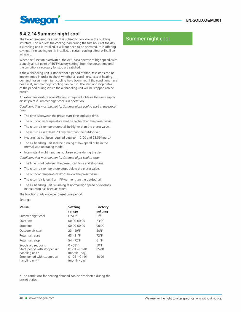
EN.GOLD.O&M.001
48 www.swegon.com We reserve the right to alter specifications without notice.
6.4.2.14 Summer night coolThe lower temperature at night is utilized to cool down the building structure. This reduces the cooling load during the first hours of the day. If a cooling unit is installed, it will not need to be operated, thus offering savings. If no cooling unit is installed, a certain cooling effect will still be achieved.
When the function is activated, the AHU fans operate at high speed, with a supply air set point of 50°F (factory setting) from the preset time until the conditions necessary for stop are satisfied.
If the air handling unit is stopped for a period of time, test starts can be implemented in order to check whether all conditions, except heating demand, for summer night cooling have been met. If the conditions have been met, summer night cooling can be run. The start and stop dates of the period during which the air handling unit will be stopped can be preset.
An extra temperature zone (Xzone), if required, obtains the same supply air set point if Summer night cool is in operation.
Conditions that must be met for Summer night cool to start at the preset time:
• The time is between the preset start time and stop time.
• The outdoor air temperature shall be higher than the preset value.
• The return air temperature shall be higher than the preset value.
• The return air is at least 2°F warmer than the outdoor air.
• Heating has not been required between 12.00 and 23.59 hours.*
• The air handling unit shall be running at low speed or be in the normal stop operating mode.
• Intermittent night heat has not been active during the day.
Conditions that must be met for Summer night cool to stop:
• The time is not between the preset start time and stop time.
• The return air temperature drops below the preset value.
• The outdoor temperature drops below the preset value.
• The return air is less than 1°F warmer than the outdoor air.
• The air handling unit is running at normal high speed or external/manual stop has been activated.
The function starts once per preset time period.
Settings:
Value Setting range
Factory setting
Summer night cool On/Off Off
Start time 00:00-00:00 23:00
Stop time 00:00-00:00 06:00
Outdoor air, start 23 - 59°F 50°F
Return air, start 63 - 81°F 72°F
Return air, stop 54 - 72°F 61°F
Supply air, set pointStart, period with stopped air handling unit* Stop, period with stopped air handling unit*
0 - 68°F01-01 – 01-01(month - day)01-01 – 01-01(month - day)
50°F05-01
10-01
Summer night cool
* The conditions for heating demand can be deselected during the preset period.

www.swegon.com 49We reserve the right to alter specifications without notice.
EN.GOLD.O&M.001
6.4.2.15 Down regulation (airflow/pressure)Down regulation of the supply air flow is the last step in the regulation sequence for heating. The supply air fan or both the supply air and return air fan can be selected. The return air fan only cannot be selected.
See also Section 6.4.2.7.
Down regulation can take place to max. of 50% of the preset value, however not lower than the min. flow or 0.08 in. WG.
Settings:
Value Setting range
Factory setting
Down regulation Inactive/Supply air/Supply air and return air
Supply air
Down regulation

EN.GOLD.O&M.001
50 www.swegon.com We reserve the right to alter specifications without notice.
6.4.3 Time and scheduleThe built-in timer enables you to control the AHU's operating mode/time. Certain other oversteering functions such as external timer, communica-tion, etc. affect the preset operating modes.
There are five different operating modes: Total stop = The AHU is completely stopped, no internal automatic func-tions or external control commands can start the AHU. Normal Stop = The AHU has stopped, however all the internal and exter-nal automatic functions oversteer the stop. Extended Normal Stop = The AHU has stopped, however all the internal and external automatic functions, with exception of Summer night cool, oversteer the stop. Low speed = The AHU is running at the preset low speed setting. High speed = The AHU is running at the preset high speed setting.
6.4.3.1 Time and dateThe current date and time can be set and adjusted if needed. The timer automatically takes leap years into consideration.
The relevant region and city can be selected, summer time/winter time change-over will then be managed automatically.
Time source can be set to manual or via SNTP (requires connection to network) and BACnet. The time format and date format can be set.
6.4.3.2 Schedule settingsThe relevant operating mode can be read under Schedule settings. Here you can also set a preselected operating mode, in which the air handling unit always operates during non-programmed time, under Day schedule and Exceptions schedule. This setting (start and stop date not activated) is used most often and covers the majority of needs.
When the start and stop date is activated, this means that during the preset period (date) preset time applies during the day schedule and the exceptions schedule, and at all other times the AHU runs in the prese-lected operating mode.
Settings:
Value Setting range
Factory settings
Preselected operating mode Total stop/Low speed/High speed/Normal Stop/ Extended Normal Stop
Low speed
Start date Active/Inactive InactiveStart date Year/Month/DayStop date Active/Inactive InactiveStop date Year/Month/Day
Time and schedule
Time and date
Schedule settings
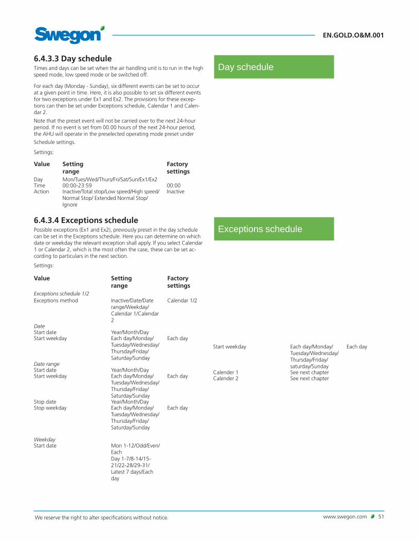
www.swegon.com 51We reserve the right to alter specifications without notice.
EN.GOLD.O&M.001
Day schedule6.4.3.3 Day scheduleTimes and days can be set when the air handling unit is to run in the high speed mode, low speed mode or be switched off.
For each day (Monday - Sunday), six different events can be set to occur at a given point in time. Here, it is also possible to set six different events for two exceptions under Ex1 and Ex2. The provisions for these excep-tions can then be set under Exceptions schedule, Calendar 1 and Calen-dar 2.
Note that the preset event will not be carried over to the next 24-hour period. If no event is set from 00.00 hours of the next 24-hour period, the AHU will operate in the preselected operating mode preset under
Schedule settings.
Settings:
Value Setting range
Factory settings
Day Mon/Tues/Wed/Thurs/Fri/Sat/Sun/Ex1/Ex2Time 00:00-23:59 00:00Action Inactive/Total stop/Low speed/High speed/
Normal Stop/ Extended Normal Stop/Ignore
Inactive
6.4.3.4 Exceptions schedulePossible exceptions (Ex1 and Ex2), previously preset in the day schedule can be set in the Exceptions schedule. Here you can determine on which date or weekday the relevant exception shall apply. If you select Calendar 1 or Calendar 2, which is the most often the case, these can be set ac-cording to particulars in the next section.
Settings:
Value Setting range
Factory settings
Exceptions schedule 1/2Exceptions method Inactive/Date/Date
range/Weekday/Calendar 1/Calendar 2
Calendar 1/2
DateStart date Year/Month/DayStart weekday Each day/Monday/
Tuesday/Wednesday/Thursday/Friday/Saturday/Sunday
Each day
Date rangeStart date Year/Month/DayStart weekday Each day/Monday/
Tuesday/Wednesday/Thursday/Friday/Saturday/Sunday
Each day
Stop date Year/Month/DayStop weekday Each day/Monday/
Tuesday/Wednesday/Thursday/Friday/Saturday/Sunday
Each day
WeekdayStart date Mon 1-12/Odd/Even/
Each Day 1-7/8-14/15-21/22-28/29-31/Latest 7 days/Each day
Exceptions schedule
Start weekday Each day/Monday/Tuesday/Wednesday/Thursday/Friday/ saturday/Sunday
Each day
Calender 1 See next chapterCalender 2 See next chapter

EN.GOLD.O&M.001
52 www.swegon.com We reserve the right to alter specifications without notice.
Calendar 16.4.3.5 Calendar 1 and 2The specific days when Exceptions schedule 1 or 2 shall apply can be set in Calendars 1 and 2. On condition that Calendar 1 or 2 is selected, see previous section. In other cases, these settings will have no effect.
There is a total of ten possible settings under each calendar and various functions can be selected for each.
Settings (For Calendar 1 and Calendar 2 respectively):
Value Setting range
Factory setting
Function 1-10 Inactive/Date/Date range/Weekday InactiveDateStart date Year/Month/DayStart weekday Each day/Monday/Tuesday/
Wednesday/Thursday/Friday/Saturday/Sunday
Each day
Date rangeStart date Year/Month/DayStop date Year/Month/DayWeekdayStart date Month 1-12/Odd/Even/Each
Day 1-7/8-14/15-21/22-28/29-31/Latest 7 days/Each day
Start weekday Each day/Monday/Tuesday/Wednesday/Thursday/Friday/Saturday/Sunday
Each day
6.4.3.6 Prolonged operationThe control unit inputs for external low speed (terminals 14-15) and external high speed (terminals 16-17) respectively, can be supplemented with Prolonged operation. They can be used for overtime running acti-vated by a push button, for example.
The required time in hours and minutes can be set as follows.
Settings:
Value Setting range
Factory setting
Ext. low speed 0:00 - 23:59 00:00 Ext. high speed 0:00 - 23:59
(hrs.:min.)00:00 (hrs.:min.)
Calendar 2
Prolonged operation

www.swegon.com 53We reserve the right to alter specifications without notice.
EN.GOLD.O&M.001
6.4.5 FiltersStatusThe current filter status and the current alarm limit can be viewed here. Used for performance checks.
CalibrationThe filters should be calibrated when the fans are started up for the first time and when the duct system, air terminals and commissioning plates, if required, have been installed and commissioned. After that every time filters are replaced. See also Section 6.3.
Pre-filter/AHU filter (GOLD SD)/End filter Filter monitoring must be activated for the filter (in addition to the inter-nal filter in the GOLD RX/PX) to be monitored.
Settings:
Value Setting range
Factory setting
Pre-filter Inactive/Supply air/Return air/Supply air and return air
Inactive
AHU filters Inactive/Supply air/Return air/Supply air and return air
Inactive
End filter On/Off Off
Alarm limitsAlarm limit for installed filters can be changed.
Setting:
Value Setting range
Factory setting
Installed filters 0-2 in W.G. 0.4 in W.G.
Filters
6.4.6 SoftwareThe current program versions for the IQlogic control unit, IQnavigator hand-held terminal and the component units on the communications bus can be viewed and updated from the SD circuit card.
Software
6.4.7 LanguageThe language desired can be set here. The appropriate language is nor-mally selected the first time the AHU is started up. However, the language setting can be changed at any time.
Settings:
Value Setting range
Factory setting
Language Available languages are displayed
English
Language
6.4.4 Energy monitoringReadings of the power consumed by fans and other AHU components can be viewed here. SFP readings for the AHU fans and the efficiency on heat transfer of the rotary heat exchanger can also be viewed. Accumu-lated energy consumption can be reset to zero. Energy
monitoring

EN.GOLD.O&M.001
54 www.swegon.com We reserve the right to alter specifications without notice.
Fire alarms
6.4.8 Alarm settings
6.4.8.1 Fire alarms
Internal fire alarmThe air handling unit’s internal temperature sensors serve as fire protec-tion thermostats. An alarm is initiated if the supply air temperature sensor registers more than 158°F or when the return air temperature sensor registers more than 122°F.
If an external Return air/Room temperature sensor is connected and activated, this works parallel with the return air temperature sensor of the AHU.
External fire alarm 1 and 2External fire alarm 1 (Terminals 6-7) and external fire alarm 2 (Terminals 8-9) are used for external fire-control equipment.
Alarm resetThe resetting of internal fire alarms as well as the external fire alarms 1 and 2 can be individually selected to manual or automatic.
After cool The After cool function for electric air heaters can be individually acti-vated, for internal fire alarms as well as external fire alarms 1 and 2.
Fan operation at fire alarm The fans of the air handling unit can be used for evacuating smoke, etc. It is possible to individually select the type of fan operation for each sepa-rate fire alarm.
If the AHU is idle, the fans selected start up (10-100%), irrespective of whether stop (all types) is activated.
The AHU's damper relay is energized and the AHU's operation relay is de-energized. The damper that should be open in event of fire, shall be con-nected to the damper relay (control unit terminals 28-30). The damper that should be closed in event of fire, shall be connected to the operation relay (terminals 26-27 of the control unit, potential-free contact).
Priority The mutual priority of the internal and the external fire alarms can be set. If automatic is selected, this means that the first input to be activated is given priority.
Alarm settings
Settings:
Value Setting range
Factory settings
Internal fire alarm On/Off OffInternal fire alarm reset Manual/Auto Manual Internal fire alarm after cool Active/Inactive InactiveExternal fire alarm 1/2, resetting
Manual/Auto Manual
External fire alarm 1/2, after cool
Active/Inactive Inactive
Fan operation on an internal fire alarm
Inactive/Supply air/Return air/Supply air and return air
Inactive
Supply air fan on an internal fire alarm
10-100% 100%
Return air fan on an internal fire alarm
10-100% 100%
Fan operation on external fire alarm 1/2
Inactive/Supply air/Return air/Supply air and return air
Inactive
Supply air fan on external fire alarm 1/2
10-100% 100%
Return air fan on external fire alarm 1/2
10-100% 100%
Order of priority External fire alarm 1/External fire alarm 2/Internal fire alarm/Automatic
External fire alarm 1

www.swegon.com 55We reserve the right to alter specifications without notice.
EN.GOLD.O&M.001
6.4.8.2 External alarmsExternal alarms can be used for external functions (control unit terminals 10-11 and 12-13).
Typical uses:
– Motor protection for the circulation pump in the heating or cooling circuit.
– Service alarm actuated by smoke detectors.
Set the following: Manual or automatic alarm reset, post-cooling for electric air heater and whether the alarm shall be activated on a closed or open circuit. The alarm can be time delayed.
Settings:
Value Setting range
Factory setting
External alarm 1 reset Manual/Auto ManualExternal alarm 1 after cool Inactive/Active ActiveExternal alarm 1 input Closed circuit/
Open circuitClosed circuit
External alarm 1 delay time
0-600 sec. 10 sec.
External alarm 2 reset Manual/Auto ManualExternal alarm 2 after cool Inactive/Active ActiveExternal alarm 2 input Closed circuit/
Open circuitClosed circuit
External alarm 2 delay time
0-600 sec. 10 sec.
External alarms
Temperature protection6.4.8.3 Temperature protectionIn the GOLD PX units, the sensor in the inlet of the supply air fan can be used as temperature protection. Alarm priority and whether the AHU shall stop or not in event of an alarm can be set under Alarm priority, se Section 6.4.8.6.
For the GOLD RX unit, it is possible to use a separate sensor and its wiring is routed to the control unit. Select sensor input 4 for supply air = right and select sensor input 3 for supply air = left.
The alarm limit and alarm delay can be set for the sensor.
Settings:
Value Setting range
Factory settings
Temperature protection On/Off OffAlarm delay 1-900 sec. 30 sec.Alarm limit 30 – 68°F 45°F

EN.GOLD.O&M.001
56 www.swegon.com We reserve the right to alter specifications without notice.
Temperature alarm limits6.4.8.4 Temperature alarm limits
Changes in the factory-preset alarm limits should only be made if you have special reasons for doing so and you should be aware of the consequences.
Pre-heating below set pointYou can preset how much the temperature downstream of the pre-heater should be permitted to be below the temperature set point before an alarm is initiated.
Supply air below/above set pointYou can preset how much the supply air temperature shall be permit-ted to be below or above the supply air temperature set point before an alarm is initiated. The alarm for supply air above the set point is normally blocked. Used in the cases in which cooling is installed.
Return air below alarm limit You can preset how much the return air temperature shall be permitted to be below the return air temperature set point before an alarm is initi-ated.
Outdoor temperature, stop limitOn tripped heat exchanger alarms, alarm numbers: 15:1-15:4, 16;1-16:4, 17:1, 17:4-17:9 (see Section 8.2), the following applies: if the outdoor air temperature is above this stop limit, an alarm only will be initiated and if it is below the stop limit, the AHU will stop and an alarm will be initiated.
Settings:
Value Setting range
Factory setting
Pre-heat below set point 2 – 15 K 5.0 KSupply air below set point 2 – 15 K 5.0 KSupply air above set point 2 – 15 K 7.0 KReturn air below alarm limit 18 68°F 54°FOutdoor temperature limit stop -40 122°F 41°F
6.4.8.6 Alarm priorityChanges in alarm priority should only be made if you have special reasons for doing so and you should be aware of the conse-quences. The priority of certain alarms cannot be changed.
Settings:
Value Setting range
Alarm number 1:1 - 60:10Active On/OffPriority Info*/A/BAir handling unit stop On/Off
* Alarms are indicated as a flashing red LED on the hand-held terminal, no group alarm is forwarded.
Alarm priority
6.4.8.5 Service periodThe air handling unit's service period can be set here. The remaining time to alarm can be read. An alarm will be initiated after the time interval has expired. If you reset the alarm in the alarm log, the alarm will trip again after 7 days. Following completed service, the alarm must always be reset in this menu and this will launch a new service interval.
Settings:
Value Setting range
Factory setting
Service period 0 – 99 months 12 months
Service period

www.swegon.com 57We reserve the right to alter specifications without notice.
EN.GOLD.O&M.001
Continuous log
6.4.9 LogAn SD card must be fitted into the AHU's control card for the log function to work (4 GB SD cards are installed from the factory.)
6.4.9.1 Continuous logThe continuous log can be activated here. The login interval is one minute (1440 logins per 24-hour period). One login file is created for each 24-hour period.
Settings:
Value Setting range
Factory settings
Log file period On/Off On
6.4.9.2 Log senderThe log function has a log sender function which can e-mail the log to an optional e-mail address and/or FTP address.
Settings:
Value Setting range
Factory setting
Log sender active On/Off OffLive mode E-mail/FTP/E-mail
and FTPE-mail
Other settings can be entered in the AHU's web page.
Log
Log sender

EN.GOLD.O&M.001
58 www.swegon.com We reserve the right to alter specifications without notice.
Settings
6.4.10 Air handling unit
6.4.10.1 SettingsSet the type of air handling unit here. The type of air handling unit is normally preset for the unit supplied; except the GOLD SD return air unit which must be set here. N.B.! Do not change the air handling unit setting to a type that differs from the one supplied. If you do so, the air handling unit will not operate satisfactorily.
The air handling unit can be given a specific name (e.g. the unit's serial number). Naming in the hand-held terminal can only be done with digits, however on the web page the naming can also be done with alphabetical characters. The given name is then shown in all the images in the hand-held terminal and web page.
The type of AHU, size of the supply air and return air fan respectively can be viewed.
GOLD RX/PXThe AHU’s fan position 1 (left-hand fan seen from the inspection side, see illustrations) can be read and preset. N.B.! This changes the function of the fans from supply air to return air and vice versa. GOLD RX size 05-100 can be changed at the site. The other variants must not be changed from the factory setting.
The fan position in the flow chart can be read and should be set accord-ing to the AHU's actual configuration.
GOLD SDThe fan position, upper or lower level, can be read and should be set according to the AHU’s actual configuration.
Settings:
Value Setting range
Factory setting
Type of air handling unit GOLD RX/GOLD PX/GOLD SD Supply air/GOLD SD Return air/GOLD SD Supply air+GOLD SD Sup-ply air+Return air/GOLD SD Supply air+Return air
Type of air handling unit supplied, except the GOLD SD return air han-dling unit
GOLD RX/PXName OptionalFan position 1 Return air/
Supply airReturn air
Flow chart, supply air fan position
Upper level/Lower level
Lower level
GOLD SDName OptionalFlowchart fan position Upper level/Lower
levelLower level
Air handling unit
GOLD RX 05-40
Fan arrangement 1
Fan arrangement 2
Fan pos. 1 set as return air (right-hand inspection side)
Fan pos. 1 set as supply air (left-hand inspection side)
Fan pos. 1 set as return air (right-hand inspection side)
Fan pos. 1 set as supply air (left-hand inspection side)

www.swegon.com 59We reserve the right to alter specifications without notice.
EN.GOLD.O&M.001
6.4.10.5 Automatic functions
Start up sequenceThe air handling unit has a start up sequence with a factory-preset time delay between each step as follows:
1. The damper relay is energized and opens the shut-off damper (if installed). The heat exchanger is controlled to max. heat recovery (not the GOLD SD without heat exchanger). The valve for reheating opens to 40% (if installed)
Time delay: 30 seconds.
2. The return air fan starts in the current operating mode (not for venti-lation systems with GOLD SD supply air handling unit only)
Time delay: 60 seconds.
3. The supply air fan starts (not for ventilation systems with GOLD SD return air handling unit only)
Time delay: 30 seconds.
4. The reheating function is ramped up or down depending on the heat-ing load. Ramp time: 180 seconds. After that the heat exchanger is ramped up or down depending on the heating load. Ramp time: 180 seconds.
The entire start up sequence can be followed in the dashboard image.
The start up sequence prevents the return air fan from starting up if the shut-off damper is closed. By first starting up the return air fan and the heat exchanger, you can avoid chilling the premises with supply air on a start up under cold weather conditions.
Zero point calibrationThe pressure sensor of the AHU is automatically calibrated. The calibra-tion process takes about 70 seconds after the AHU has stopped (a noti-fication is shown if the AHU has not stopped). The zero point calibration text is displayed in the hand-held terminal. The fans cannot start while calibration is in progress.
Operation time6.4.10.3 Operation timeIn operation times (in days) can if applicable be viewed for fan controls, heat exchanger/cooling recovery, preheating, extra heating regulation sequence, Xzone heating, AHU reheating, ReCO2 heating, extra cooling regulation sequence, Xzone cooling, AHU cooling, ReCO2 cooling, AYC heating water and AYC cooling water.
Fan status6.4.10.2 Fan statusThe fan control speed setting can be viewed in percent of max. speed here.
6.4.10.4 VOC/CO2 sensorYou can select here the operating mode for the VOC sensor and the CO2 unit. The VOC level can be read. The VOC sensor position in the flow chart can be selected if only monitoring has been selected.
Settings:
Value Setting range
Factory setting
VOC sensor mode Inactive/Monitoring only/Monitoring and regulation
Inactive
CO2 unit %/ppm %Flow chart, VOC sensor position Supply air/
Return airSupply air
VOC/CO2 sensor

EN.GOLD.O&M.001
60 www.swegon.com We reserve the right to alter specifications without notice.
Heat
6.4.11 Heat
6.4.11.1 Status All the relevant values can be read here. Used for performance checks.
6.4.11.2 Pre-heatBy preheating the outdoor air, it is possible to prevent moisture precipita-tion in the AHU's outdoor air filter, to reduce the risk of frosting in the heat exchanger and to eliminate the risk that pressure sensors and motor control systems are operating in too low ambient temperature.
Scope for setting Outdoor air temperature related preheat is available.
See also the Pre-heat function guide for more detailed information.
Settings:
Value Setting range
Factory setting
Pre-heat On/Off OffPre-heat set pointOutdoor air temperature related Difference, outdoor air temperature Preheat, min. limit
−40 - 104°FOn/Off
0–25 K
−40 - 104°F
41°F
5 K
14°FPeriodic operation of pump On/Off OnPeriodic operation of valve On/Off OnPeriodic operation interval 0 - 168 hrs. 24 hrs.Periodic operation period 0 - 60 min. 3 min.Alarm input, function Inactive/Alarm
on open contact/Alarm on closed contact/Contactor function
Inactive
Status
Pre-heat

www.swegon.com 61We reserve the right to alter specifications without notice.
EN.GOLD.O&M.001
6.4.11.3 Extra regulation sequences 1 and 2Used for extra regulation functions controlled by a 0-10 V (10-0 V) signal with ordinary temperature regulation sequence.
The function can be used for utilizing existing heating or cooling sources, such as from a chiller. The function can also be used for an extra air heater or air cooler.
It can also be used for controlling dampers for recirculation, if required. In these cases, an inverted 10-0 V output is used.
Recirculation control is used for the ABBD mixing section (GOLD SD only) The 10-0 V inverted output should be in the On position.
The maximum output signal can be limited from 100% down to 0 %.
The output signal of the extra regulation sequence is controlled from the ABIQ-3-2 IQlogic+ module accessory, see separate installation instructions.
The extra regulation sequence makes it possible to control two air heaters at the same time in the following combinations: water - electricity, water - water, electricity - electricity (Season heat, see also Section 6.4.11.7). The air heater for hot water is available without or without frost guard function.
When the output of the first air heater is not sufficient, the second is automatically brought into the sequence.
A start-up sequence, frost guard function, pump control, post-cooling for electric air heater and other functionality are available.
For the start-up sequence, frost guard function, periodic operation and post-cooling, the same settings are used as for regular reheating.
Settings:
Value Setting range
Factory setting
Extra regulation sequence 1/2 Inactive/Heat/Cool/Heat and cool
Inactive
Inverted output 10-0V On/Off OffRecirculation control On/Off OffMax. output signal 0-100% 100%Periodic operation of pump On/Off OnPeriodic operation of valve On/Off OnPeriodic operation interval 0-168 hrs. 24 hrs.Periodic operation period 0-60 min. 3 min.Pump alarm Inactive/Alarm on
open contact/Alarm on closed contact/Contactor function
Inactive
Extra regulation sequence 1/2

EN.GOLD.O&M.001
62 www.swegon.com We reserve the right to alter specifications without notice.
6.4.11.4 ReheatThe air heater is equipped with a quick-fit connector for connection to the AHU's control unit which automatically senses the type of air heater in use.
Air heater for hot waterWhen there is a reheating load, and the function Periodic operation of pump or of pump+valve is selected , the relay output is activated (con-trol unit terminals 20-21) and this starts the circulation pump of the air heater.
If the outdoor temperature is low (colder than 54°F), the pump output contact is continuously activated. During other times, the pump output contact is activated 3 min./day (factory setting) for periodic operation the circulation pump.
Settings:
Value Setting range
Factory setting
Air heater for hot waterPeriodic operation of pump On/Off OnPeriodic operation of valve On/Off OnPeriodic operation interval 0-168 hrs. 24 hrs.Periodic operation period 0-60 min. 3 min.
Electric air heaterWhen there is a reheating load, the relay output is activated (control unit terminals 20-21).
The relay output can be used for indicating or blocking the external func-tion.
Reheat
Xzone6.4.11.5 XzoneThe Xzone temperature control function is designed for controlling one extra temperature zone via the ventilation system.
Xzone can be used for all types of air handling units, and both reheating and cooling can be controlled in the extra zone.
See also the Xzone function guide for more detailed information.
Settings:
Value Setting range
Factory setting
Xzone On/Off OffAir heater for hot waterPeriodic operation of pump On/Off OnPeriodic operation of valve On/Off OnPeriodic operation interval 0-168 hrs. 24 hrs.Periodic operation period 0-60 min. 3 min.Alarm input, function Inactive/Alarm on
open contact/Alarm on closed contact/Contactor function
Inactive

www.swegon.com 63We reserve the right to alter specifications without notice.
EN.GOLD.O&M.001
6.4.11.6 Electric air heaterIf the electric air heater has been in operation, the air heater is post-cooled for about 3 minutes (factory setting) when stop has been acti-vated.
The text “After cool” appears in the hand-held terminal.
Settings:
Value Setting range
Factory setting
After cool 1 - 25 min 3 min.
Electric air heater
6.4.11.7 Season HeatThe Season Heat function involves that the extra regulation sequence 1 functions is activated. See Section 6.4.11.3.
When both the standard function for reheating and the extra heating sequence are activated, it is possible to alternate between these via a digital input or communication.
Example: Hot water is only available in the winter. In the summer, any reheating load is backed up by an electric air heater. Changeover can be done manually or via external thermostat, external clock function or the like.
Settings:
Value Setting range Factory settingSeason Heat Inactive/Extra reg.
seq. 1 closed contact/Extra reg. seq. 1 open contact/Extra reg. seq. 1 Manual 1)
Inactive
Extra reg. seq. enabled(manual only)
On/Off 2) Off
Season Heat
6.4.11.8 Automatic functions
Frost guard function, air heater for waterThe frost guard function is always active if the connected air heater for hot water has been supplied by Swegon.
The function activates a heating device that keeps the temperature in the coil at 55°F while the air handling unit is operating and 77°F in the coil when the unit is stopped. An alarm is initiated and stops the AHU if the temperature sensor senses a temperature below 45°F.
Capacity reduction of the electric air heaterOnly in combination with Swegon's electric air heater.
A min. permissible air velocity of 394 fpm is required for preventing the electric heating elements from becoming overheated when they are generating full heating output.
If the air handling unit supply airflow drops below the value that cor-responds to an air velocity of 394 fpm across the heat exchanger, the heating output of the air heater will be automatically reduced.
1) Extra regulation sequence 1 closed contact = When the contact is closed, only the standard reheating function is active. When the contact is opened a changeover to extra heating regulation sequence occurs. Extra regulation sequence 1 open contact = When the contact is open, only the standard reheating function is active. When the contact is closed, a changeover to extra heating regulation sequence occurs.Extra regulation sequence 1 Manual = Changeover is done in the hand-held terminal or on the AHU's web page.2) Extra regulation sequence in Off position involves that the standard function for reheating is active and in the On position a changeover to extra regulation sequence occurs.

EN.GOLD.O&M.001
64 www.swegon.com We reserve the right to alter specifications without notice.
Status
Extra regulation sequence 1/2
6.4.12 Cool
6.4.12.1 Status All the relevant values can be read here. Used for performance checks.
6.4.12.2 Extra regulation sequences 1 and 2Used for extra regulation functions controlled by a 0-10 V (10-0 V) signal with ordinary temperature regulation sequence.
The function can be used for utilizing existing heating or cooling sources, such as from a chiller. The function can also be used for an extra air heater or air cooler.
It can also be used for controlling dampers for recirculation, if required. In these cases, an inverted 10-0 V output is used.
Recirculation control is used for the ABBD mixing section (GOLD SD only) The 10-0 V inverted output should be in the On position.
The maximum output signal can be limited from 100% down to 0 %.
The output signal of the extra regulation sequence is controlled from the ABIQ-3-2 IQlogic+ module accessory, see separate installation instructions.
Settings:
Value Setting range
Factory setting
Extra regulation sequence 1/2 Inactive/Heat/Cool/Heat and cool
Inactive
Output inverse 10-0V On/Off OffRecirculation control On/Off OffMax. output signal 0-100% 100%Periodic operation of pump On/Off OnPeriodic operation of valve On/Off OnPeriodic operation interval 0-168 hrs. 24 hrs.Periodic operation period 0-60 min. 3 min.Pump alarm Inactive/Alarm on
open contact/Alarm on closed contact/Contactor function
Inactive
Cool

www.swegon.com 65We reserve the right to alter specifications without notice.
EN.GOLD.O&M.001
6.4.12.3 CoolThe valve actuator of the air cooler for water is equipped with a quick-fit connector for connection to the AHU's control unit which automatically activates the cooling function.
1-stepUsed if cooling in one step is connected. The cooling controller of the AHU regulates the cooling output according to the cooling load, 0-100 %. The cooling relay is energized when the cooling load exceeds 5 % and is de-energized when the cooling load is below 2 %.
2-stepUsed when cooling in 2 steps is connected. The cooling controller of the AHU regulates the cooling output according to the cooling load, 0-100 %.
Cooling relay 1 is energized when the cooling load exceeds 5 % and is de-energiszed when the cooling load is less than 2 %. Cooling relay 2 is energized when the cooling load exceeds 55 % and is de-energized when the cooling load is less than 50 %.
3-step, binaryUsed when cooling with two inputs controlled with three binary steps is connected. The cooling controller of the AHU regulates the cooling output according to the cooling load, 0-100 %.
On an increasing cooling load:
Cooling relay 1 is energized when the cooling load is above 5 % and is de-energized when the cooling load is between 40-70 %. Cooling relay 2 is energized when the cooling load is above 40 %. Cooling relay 1 is energized again (together with cooling relay 2) when the cooling load is above 70%.
On a decreasing cooling load:
Cooling relay 1 is de-energized when cooling load is below 60 %, it is energized again when cooling load is below 30 % and is de-energized again when cooling load is below 2 %. Cooling relay 2 is de-energized when cooling load is below 30 %.
Settings:
Value Setting range
Factory setting
Cooling Inactive/1 step/2 steps/3 steps, binary
Inactive
Air cooler for waterPeriodic operation of pump 1 On/Off OnPeriodic operation of pump 2 On/Off OnPeriodic operation of valve On/Off OnPeriodic operation interval 0-168 hrs. 24 hrs.Periodic operation period 0-60 min. 3 min.
Cool

EN.GOLD.O&M.001
66 www.swegon.com We reserve the right to alter specifications without notice.
Xzone6.4.12.4 XzoneThe Xzone temperature control function is designed for controlling one extra temperature zone via the ventilation system.
Xzone can be used for all types of air handling units, and both reheating and cooling can be controlled in the extra zone.
See also the Xzone function guide for more detailed information.
Settings:
Value Setting range
Factory setting
Cooling Inactive/1 step/2 steps/3 steps, binary
Inactive
Air cooler for waterPeriodic operation of pump 1 On/Off OnPeriodic operation of pump 2 On/Off OnPeriodic operation of valve On/Off OnPeriodic operation interval 0-168 hrs. 24 hrs.Periodic operation period 0-60 min. 3 min.Alarm input 1, function Inactive/Alarm on
open contact/Alarm on closed contact/Contactor function
Inactive
Alarm input 2, function Inactive/Alarm on open contact/Alarm on closed contact/Contactor function
Inactive

www.swegon.com 67We reserve the right to alter specifications without notice.
EN.GOLD.O&M.001
6.4.12.5 Delay timeRestart time is computed from when the compressor starts until it is permitted to start again.
Step switch time is the time delay between two steps.
Stop/start time is computed from when the compressor stops until it is permitted to start again.
Settings:
Value Setting range
Factory setting
Restart time 0-20 min. 5 min.Step switch time 0-15 min. 5 min.Stop/start time 0-15 min. 5 min.
6.4.12.6 Outdoor air limitsProvision is available for setting an outdoor temperature-related blocking function in 3 steps. If the outdoor temperature is below each step limit, the function of the cooling relays will be blocked. The function is used for preventing the relevant compressors from being switched on and off too many times.
Settings:
Value Setting range
Factory setting
Step 1 32 – 86°F 59°FStep 2 32 – 86°F 64°FStep 3 32 – 86°F 68°F
6.4.12.7 Airflow, limits
Cooling, 0-10 V:The cooling function is blocked if the supply or return airflows are lower than the preset limit.
If the airflow limit function is not of immediate interest, both flow limits are set to 0.
Cooling, On/Off:The current airflow must exceed the preset airflow as a condition for the respective cooling step to be put into operation.
Settings:
Value Setting range
Factory settings
Cooling, 0-10 VSupply air, 0-10 V 0 - Max. flow 25% of max. airflow for
air handling unitReturn air, 0-10 V 0 - Max. flow 25% of max. airflow for
air handling unitCooling, On/OffSupply air, On/Off, step 1 0 - Max. flow 25% of max. airflow for
air handling unitReturn air, On/Off, step 1 0 - Max. flow 25% of max. airflow for
air handling unitSupply air, On/Off, step 2 0 - Max. flow 50% of max. airflow for
air handling unitReturn air, On/Off, step 2 0 - Max. flow 50% of max. airflow for
air handling unitSupply air, On/Off, step 3 0 - Max. flow 75% of max. airflow for
air handling unitReturn air, On/Off, step 3 0 - Max. flow 75% of max. airflow for
air handling unit
Delay time
Outdoor air limits
Air flow limits

EN.GOLD.O&M.001
68 www.swegon.com We reserve the right to alter specifications without notice.
Status
Carry over control
6.4.13 Heat/Cool recovery
6.4.13.1 StatusAll the relevant values can be read here. Used for performance checks. Heat/Cool
recovery
6.4.13.2 Carry over controlIf the fans are generating low airflows, the rotary heat exchanger is decelerated to an appropriate speed to ensure a correct purg-ing airflow through the heat exchanger.
Settings:
Value Setting range
Factory setting
Carry over control On/Off Off
Efficiency measurement6.4.13.3 Efficiency measurementThe efficiency measurement of heat exchangers for RX/PX can be ena-bled here.
The function requires two extra sensors, ABLZ-2-31-2 (extract air) and ABLZ-2-31-4 (exhaust air) which measure temperature and humidity. See the separate installation instructions.
Measured values are specified under the humidity function.
Settings:
Value Setting range
Factory setting
Efficiency measurement On/Off Off
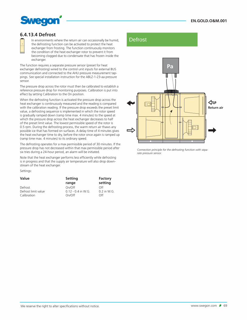
www.swegon.com 69We reserve the right to alter specifications without notice.
EN.GOLD.O&M.001
6.4.13.4 DefrostIn environments where the return air can occasionally be humid, the defrosting function can be activated to protect the heat exchanger from frosting. The function continuously monitors the condition of the heat exchanger rotor to prevent it from becoming clogged due to condensate that has frozen inside the exchanger.
The function requires a separate pressure sensor (preset for heat exchanger defrosting) wired to the control unit inputs for external BUS communication and connected to the AHU pressure measurement tap-pings. See special installation instruction for the ABLZ-1-23-aa pressure sensor.
The pressure drop across the rotor must then be calibrated to establish a reference pressure drop for monitoring purposes. Calibration is put into effect by setting Calibration to the On position.
When the defrosting function is activated the pressure drop across the heat exchanger is continuously measured and the reading is compared with the calibration reading. If the pressure drop exceeds the preset limit value, a defrosting sequence is implemented in which the rotor speed is gradually ramped down (ramp time max. 4 minutes) to the speed at which the pressure drop across the heat exchanger decreases to half of the preset limit value. The lowest permissible speed of the rotor is 0.5 rpm. During the defrosting process, the warm return air thaws any possible ice that has formed on surfaces. A delay time of 4 minutes gives the heat exchanger time to dry, before the rotor once again is ramped up (ramp time max. 4 minutes) to its ordinary speed.
The defrosting operates for a max permissible period of 30 minutes. If the pressure drop has not decreased within that max permissible period after six tries during a 24-hour period, an alarm will be initiated.
Note that the heat exchanger performs less efficiently while defrosting is in progress and that the supply air temperature will also drop down-stream of the heat exchanger.
Settings:
Value Setting range
Factory setting
Defrost On/Off OffDefrost limit value 0.12 - 0.4 in W.G. 0.2 in W.G.Calibration On/Off Off
Connection principle for the defrosting function with sepa-rate pressure sensor.
Return air
Defrost

EN.GOLD.O&M.001
70 www.swegon.com We reserve the right to alter specifications without notice.
6.4.13.6 Automatic functions
GOLD RX (rotary heat exchanger)Purging function Purging is an automatic function that prevents the rotary heat exchanger from standing still in the same position for a longer period when no heat-ing is necessary.
Purging operation is activated when the AHU is operating but the heat exchanger rotor is not rotating. The heat exchanger rotor then rotates for 10 seconds every 10 minutes to purge its surfaces clean of impurities.
Calculation of the efficiency The efficiency is calculated and displayed (0 – 100%).
Calculation of recovered energy Recovered sensible energy is calculated and the values are displayed (instantaneous and accumulated).
Cooling recovery Cooling recovery is an automatic function that helps the air handling unit on a cooling load and high outdoor air temperature to utilize the rela-tive "cooling energy" that can be indoors. The heat exchanger rotates at max. speed and in this way recovers the relative cooling energy or chilli-ness in the return air.
The conditions for this function to be activated are that there is a cooling demand and that the outdoor temperature is 1°F higher than the return air. The function stops when the cooling load ceases to exist or when the outdoor temperature is the same as that of the return air.
Overtime heat exchanger operation If the AHU stops, the heat exchanger automatically continues to recover heat for about 1 minute.
It takes a little time for the fans to stop rotating after a stop has been ordered and this prevents the supply air from chilling the premises.
GOLD SD (coil heat exchanger)Pump control, coil heat exchanger The pump of the pipework package starts when heat recovery is needed. If heat recovery is not needed for more than 24 hours, the pump is exer-cised once a day.
Anti-frost protection
In cold weather, and if the return air is humid, there is risk of frosting in the coil heat exchanger. The GOLD SD is equipped with anti-frosting protection.
The temperature of the liquid circulated to the return air coil and the humidity in the return air are measured.
Taking the humidity into consideration, the control system calculates the lowest permissible temperature without risk of frosting inside the coil. The valve in the pipework package is then regulated to prevent the circulated liquid from dropping below this temperature.
GOLD PX (plate heat exchanger)In cold weather, and when the return air is humid, there is risk of frost-ing in the plate heat exchanger. The GOLD PX is therefore equipped with anti-frost protection.
Anti-frost protection, standard The pressure drop across the heat exchanger and the outdoor air tem-perature are measured.
With consideration given to the pressure drop across the heat exchanger and the outdoor air temperature, the control system regulates damp-ers for bypass and heat exchanger (interlinked) in order to prevent the formation of frost.
RECOfrost anti-frost protection The pressure drop across the heat exchanger, return air temperature, moisture content in the return air and outdoor air temperature are measured.
With consideration given to the pressure drop across the heat exchanger, the return air temperature, the moisture content in the return air and the outdoor air temperature, the control system individually regulates damp-ers for bypass and the heat exchanger for section-by-section defrosting without the formation of frost.
Calibration/Optimization6.4.13.5 Calibration/Optimization (GOLD PX)
Defrosting, Standard When the air handling unit is started up or if needed, a calibra-tion should be carried out. When calibration is in progress, the air handling unit's limit values for alarms and defrosting are calculated.
Defrosting, RECOfrostWhen the air handling unit is started up or if needed, a calibration should be carried out. When calibration is in progress, the air handling unit's limit values for alarms and defrosting are calculated.
When the air handling unit is started up or if needed, bypass optimiza-tion should be carried out. When bypass optimization is in progress, the damper positions of the bypass are optimized.
Calibration and bypass optimization can be activated to occur at the same time or individually. If they are activated individually, whichever one is activated first is of no importance.
Settings:
Value Setting range
Factory settings
Calibration On/Off OffBypass optimization (RECOfrost only)
On/Off Off

www.swegon.com 71We reserve the right to alter specifications without notice.
EN.GOLD.O&M.001
6.4.15 HumidityIf the functions Dehumidifying regulation and Humidifying are activated at the same time, Dehumidifying regulation has priority and the possible settings for Humidifying are limited to being the same or lower than the setting for Dehumidifying regulation. There is a delay of 5 minutes between Dehumidifying regulation having stopped and Humidifying starting up (and vice versa).
6.4.15.1 StatusAll the relevant values can be read here. Used for performance checks.
Humidity
Status
6.4.15.2 Humidifying
Evaporative humidification (On/Off)This function is suitable together with an evaporative humidifier (not Swegon).
The function requires the ABIQ-3-1 IQlogic+ module accessory and one ABLZ-31-2 humidity sensor. See separate installation instructions. Install the humidity sensor in the return air duct (or in the premises), see draw-ing.
The humidity in the return air duct (the premises) is regulated between adjustable start and stop limits.
Steam humidification (0 - 10V)The function is appropriate for operation together with a steam humidi-fier (not supplied by Swegon) and is a variable control system via 0-10 V control signal, as well as a contact function which interlocks the humidi-fier if the air handling unit stops, if Summer night cool is used or if the humidity in the supply air exceeds the set point by more than 10%.
The function requires the ABIQ-3-1 IQlogic Plus module accessory and one ABLZ-31-1 humidity sensor accessories (for supply air regulation) or two ABLZ-31-1/2 humidity sensor accessories (for return air regulation), see separate installation instructions. Install the humidity sensors in the return air duct and the supply air duct respectively. See drawing!
The function keeps the humidity level constant in the return air duct (the premises) by regulating the humidity in the supply air. In order to prevent the humidity in the supply air from being too high, it is restricted to a maximum limit.
Alternatively the humidity in the supply air duct can be kept constant by selecting a regulating humidity sensor in the supply air.
The set point cannot be set higher than the max limit. If the dehumidifi-cation function is activated, the max limit cannot be set higher than the set point for dehumidification.
Settings:
Value Setting range
Factory setting
Humidifying Inactive/On/Off/ 0-10V
Inactive
Regulation sensor Supply air/Return air Supply airEvaporativeStart 10 - 95%RH 40%RHStop 10 - 95%RH 45%RHSteamSet point 10 - 95%RH 30%RHMax. supply air 10 - 95%RH 80%RH
Example, steam humidification
ABLZ-1-31-1 Humidity sensor, supply air
ABLZ-1-31-2 Humidity sensor, return air
Humidifying

EN.GOLD.O&M.001
72 www.swegon.com We reserve the right to alter specifications without notice.
6.4.15.3 DehumidifyingThe function is intended for dehumidifying the supply air in order to prevent condensation in the supply air duct or in connected air condition-ing products.
The dehumidification regulation function controls the humidity in the supply air duct or the return air duct by means of an air cooler and an air heater for reheating.
The function requires that an air cooler be mounted upstream of the air heater in the supply air duct. See the example to the right.
If control of the humidity in the supply air duct is required, install a ABLZ-1-31-1 humidity sensor in the supply air duct. If control of the humidity in the return air duct is required, install a ABLZ-1-31-2 humidity sensor in the return air duct and a ABLZ-1-31-1 humidity sensor in the supply air duct. Connect the sensor to the AHU. See separate installation instruc-tions.
Cooling energy is emitted to condense the moisture in the supply airflow, which then is heated to the desired supply air temperature. This causes a reduction in the moisture content of the supply air.
The cooling unit used must be sized so that the temperature of the supply air will be below the dew point, otherwise no condensation will arise and no dehumidification will occur.
Settings:
Value Setting range
Factory settings
Dehumidification Inactive/Supply air/Return air
Inactive
Supply air - relative humidity 10-90%RH 50%RHReturn air - relative humidity 10-90%RH 50%RH
Dehumidifying
6.4.15.4 Humidifier alarmThe alarm input can be selected to closed circuit, open circuit or contac-tor function.
Settings:
Value Setting range
Factory setting
Alarm input Inactive/Closed circuit/Open circuit/Contactor function 1)
Inactive
1) Closed circuit involves closing the circuit in order to initiate an alarm. Open circuit involves opening the circuit in order to initiate an alarm. Contactor function involves the use of an auxiliary contact from a contac-tor, which controls the humidifier. The aux. contact is connected to the alarm input.
Humidifier alarm
Temperature sensor, supply air
ABLZ-1-31-1 Humidity sensor
Example: Dehumidification regulation
ABLZ-1-31-2 Humidity sensor

www.swegon.com 73We reserve the right to alter specifications without notice.
EN.GOLD.O&M.001
6.4.16 ReCO2The ReCO2 function is designed for ensuring the correct air qual-ity or air temperature, by means of recirculating return air and minimizing the inflow of outdoor air.
The function can be used in ventilation systems in which recirculated air intermixture is acceptable.
The function presupposes that the outdoor air damper and the damper in the air recirculation section are equipped with modulating damper actuators.
Lower outdoor air and exhaust air flows as well as lower return air fan speed enable the unit to consume less power. A separate air quality sensor continuously measures the air quality of the ventilation system.
The pressure drop across the rotor must then be calibrated to establish a reference pressure drop for the function. Calibration is put into effect by setting Calibration to the On position.
For more information, see the ReCO2 function guide.
Settings:
Value Setting range
Factory setting
Regulation mode
CO2/VOC, operating mode Inactive/ CO2/VOC / CO2/VOC and air flow boost
Inactive
Temperature mode Inactive/Heat sequence/Cool sequence/Heat and cool sequence
Inactive
CO2/VOCSet point 0 - 100% 50%CO2, set point 0 - 10000 ppm 1000 ppmVOC, set point 0 - 10000 ppm 1500 ppmMin. outdoor air 1) 25% of max.
airflow for air handling unit
Min. exhaust air 1) 25% of max. airflow for air handling unit
Calibration On/Off OffTemperatureMin. outdoor air 1) 25% of max.
airflow for air handling unit
Min. exhaust air 1) 25% of max. airflow for air handling unit
Calibration On/Off Off
1) The setting range is the same as the AHU's min. - max. settings.
Return air
Supply air
Exhaust air
Outdoor air
Pressure sensor for outdoor air measurement
Outdoor airflow kept constant by pressure sensor
When the recirculation damper opens the return air fan speed decreases and vice versa.
ReCO2

EN.GOLD.O&M.001
74 www.swegon.com We reserve the right to alter specifications without notice.
6.4.17 All Year ComfortThe All Year Comfort function controls, via control valves, the supply flow temperature to the comfort modules, cooling beams, perimeter wall units, etc. The water temperature is measured by two strap-on tempera-ture sensors mounted on the water pipe of each circuit.
All Year Comfort has functions for outdoor compensation, room com-pensation, night compensation, dew point compensation as well as the monitoring and exercising of pumps and valves.
For more information, see the All Year Comfort function guide.
Settings:
Value Setting range
Factory setting
Function Inactive/Cooling water/Heating water/
Inactive
Cooling water and heating water
Chilled waterChilled water 1) 41 – 86°F 57°FOutdoor temp compensation On/Off OffOutdoor temp X1 -40 – 104°F 122°FOutdoor temp X2 -40 – 104°F 68°FOutdoor temp X3 -40 – 104°F 77°FOutdoor temp X4 -40 – 104°F 86°FChilled water temp Y1 41 – 86°F 72°FChilled water temp Y2 41 – 86°F 64°FChilled water temp Y3 41 – 86°F 57°FChilled water temp Y4 41 – 86°F 54°FOutdoor temp for pump start -40 – 104°F 50°FOutdoor temp for pump stop -40 – 104°F 50°F
Room temp compensation On/Off OffRoom temp. set point 32 – 104°F 70°FRoom temp. P-band 1 - 10 K 5 KRoom comp. night block On/Off Off
Night compensation On/Off OffNight reduction 0 - 10 K 2 KTime channel 1/2 start of night 00:00 - 23:59 00:00Time channel 1/2 end of night 00:00 - 23:59 00:00Time channel 1/2 period Inactive/Monday/
Tuesday/Wednesday/Thursday/Friday/Saturday/Sunday Mon - Fri/Mon - Sun/ Sat - Sun
Inactive
Dew point compensation On/Off OffAir flow compensation On/Off OffPeriodic operation pump On/Off OnPeriodic operation valve exercising On/Off OffPeriodic operation interval 0-168 hrs. 24 hrs.Periodic operation period 0-60 min. 3 min.Pump alarm Inactive/Alarm on
closed contact/Alarm on open contact/Contactor function
Inactive
Valve alarm On/Off OffHeated waterHeated water1) 50 - 176°F 86°FOutdoor temp compensation On/Off OffOutdoor temp X1 −40 - 104°F −4°FOutdoor temp X2 −40 - 104°F 32°FOutdoor temp X3 −40 - 104°F 41°FOutdoor temp X4 −40 - 104°F 59°FHeated water temp Y1 50 – 176°F 104°FHeated water temp Y2 50 – 176°F 68°FHeated water temperatue Y3 50 – 176°F 68°FHeated water temp Y4 50 – 176°F 59°F
Outdoor temp for pump start -40 - 104°F 59°FOutdoor temp for pump stop -40 – 104°F 54°F
Room temp compensation On/Off OffRoom temp. set point 32 - 104°F 70°FRoom temp. P-band 1 - 10 K 5 KRoom comp. night block On/Off OffNight compensation On/Off OffNight reduction 0 – -10 K -2 KTime channel 1/2 start of night 00:00 - 23:59 00:00Time channel 1/2 end of night 00:00 - 23:59 00:00Time channel 1/2 period Inactive/Monday/
Tuesday/Wednesday/Thursday/Friday/Saturday/Sunday Mon - Fri/Mon - Sun/ Sat - Sun
Inactive
Air flow compensation On/Off OffPeriodic operation pump On/Off OnPeriodic operation valve exercising On/Off OffPeriodic operation interval 0-168 hrs. 24 hrs.Periodic operation period 0-60 min. 3 min.Pump alarm Inactive/Alarm on
closed contact/Alarm on open contact/Contactor function
Inactive
Valve alarm On/Off Off
All Year Comfort
1) Omitted if the outdoor temperature compensation is selected.

www.swegon.com 75We reserve the right to alter specifications without notice.
EN.GOLD.O&M.001
6.4.19 Inputs/OutputsCan for example be used if the air handling unit will be controlled/moni-tored via microprocessor substation or a PLC system.
External operation module 3/6 requires the ABIQ-3-2 IQlogic+ module accessory; external communication module A/B/C requires the ABIQ-3-1 accessory. See separate installation instructions.
Settings:
Value Setting range
Factory setting
External operation module 3/6Digital output 1/2 mode
Inactive/Air handling unit in operation/Air handling unit in auto operation/ Air handling unit in manual operation/Air handling unit in low speed operation/Air handling unit in high speed operation/A alarm/B alarm/Damper relay/Heat exchanger/Heat exchanger defrost/Reheat/ Reheating power reduction/Heat-ing Boost/Morning Boost/Inter-mittent night heat/Airflow down regulation/Extra reg. sequence 1/2 heat/Extra reg. sequence 1/2 cool/Cooling/Cooling Boost/Summer night cool/ Supply air fan in opera-tion/Return air fan in operation/Internal fire alarm tripped/External fire alarm 1/External fire alarm 2/External fire alarm 1 or 2/Any fire alarm
Inactive
Digital input 1/2 Inactive/Alarm reset/Stop AYC heated water/Stop AYC chilled water
Inactive
Analogue output 1 Indicates present supply airflow, from 0 to air handling unit’s max. speed (%)
Analogue output 2 Indicates present return airflow, from 0 to air handling unit’s max. speed (%)
Analogue input 1/2* Inactive/Set point displacement/Set point displacement, supply air/Set point displacement, return air
Inactive
External communica-tion module A/B/CExternal communica-tion module A/B/C
On/Off Off
Temperaturesensor no. 1
On/Off Off
Temperaturesensor no. 2
On/Off Off
* If analogue inputs 1 and 2 are both selected for setpoint displacement, only analogue input 1 will be used.
Inputs/Outputs
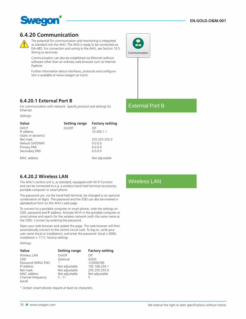
EN.GOLD.O&M.001
76 www.swegon.com We reserve the right to alter specifications without notice.
6.4.20 CommunicationThe potential for communication and monitoring is integrated as standard into the AHU. The AHU is ready to be connected via EIA-485. For connection and wiring to the AHU, see Section 10.5 Wiring to terminals.
Communication can also be established via Ethernet without software other than an ordinary web browser such as Internet Explorer.
Further information about interfaces, protocols and configura-tion is available at www.swegon.se (com).
Communication
External Port B
Wireless LAN6.4.20.2 Wireless LANThe AHU's control unit is, as standard, equipped with Wi-Fi function and can be connected to e.g. a wireless hand-held terminal (accessory), portable computer or smart phone.
The password can, via the hand-held terminal, be changed to an optional combination of digits. The password and the SSID can also be entered in alphabetical form on the AHU's web page.
To connect to a portable computer or smart phone, note the settings on SSID, password and IP address. Activate Wi-Fi in the portable computer or smart phone and search for the wireless network (with the same name as the SSID). Connect by entering the password.
Open your web browser and update the page. The web browser will then automatically connect to the control circuit card. To log on, write your user name (local or installation), and enter the password (local = 0000, installation = 1111, factory setting).
Settings:
Value Setting range Factory settingWireless LAN On/Off OffSSID Optional GOLDPassword (WPA2-PSK) 1) 123456789IP address Not adjustable 192.168.234.1Net mask Not adjustable 255.255.255.0MAC address Not adjustable Not adjustableChannel (frequency band)
5 - 11 5
1) Certain smart phones require at least six characters.
6.4.20.1 External Port BFor communication with network. Specify protocol and settings for Ethernet.
Settings:
Value Setting range Factory settingDHCP On/Off OffIP address (static or dynamic) Net maskDefault GATEWAYPrimary DNSSecondary DNS
10.200.1.1
255.255.255.00.0.0.00.0.0.00.0.0.0
MAC address Not adjustable

www.swegon.com 77We reserve the right to alter specifications without notice.
EN.GOLD.O&M.001
6.4.20.4 EIA-485Specify protocol and settings for EIA-485.
Settings:
Value Setting range Factory settingProtocol Inactive/Modbus/EXOline/
Metasys N2 Open/LONModbus
Baud rate 4800/9600/19200/38400 9600Parity None/Even/Odd NoneStopbits 1/2 2Modbus ID/Metasys ID/PLA
1 - 247 1
ELA 1-255 1Shortest feedback delay
0 - 100 ms 0 ms
EIA-485
6.4.20.5 Modbus TCPSpecify settings for Modbus TCP.
Settings:
Value Factory settingPort number 502Approved client IP address 0.0.0.0Approved client netmask 0.0.0.0
Modbus TCP
6.4.20.3 E-mailYou can select whether the AHU shall handle outgoing e-mail here.
The settings can be entered on the AHU web page. See separate instruc-tions.
There is a button for test transmission.
Settings:
Value Setting range
Factory setting
SMTP server External/Internal ExternalSMTP server Optional addressSMTP port number 25SMTP username Optional, to be entered on the
web pageSMTP password Optional, to be entered on the
web pageEncryption On/Off OffE-mail sender Optional, to be entered on the
web pageE-mail reply path Optional, to be entered on the
web page
6.4.20.6 BACnet IPEnter the BACnet IP settings.
Settings:
Value Factory settingNetwork number Ext. B 0Internal network number A 0Device ID 0Port number 47808
BACnet IP

EN.GOLD.O&M.001
78 www.swegon.com We reserve the right to alter specifications without notice.
6.4.20.8 Operation level communicationIt is possible to change the operation level communication here.
Settings:
Value Setting range Factory settingOperation level communication
Inactive/Total stop/Low speed/High speed/Normal stop/ Extended normal stop
Inactive
Operation level Communication
6.4.20.7 EXOline TCPEXOline can be activated and enter the port number.
Settings:
Value Setting range
Factory setting
Port number 26486PLA 1 - 247 1ELA 1-255 1
EXOline TCP

www.swegon.com 79We reserve the right to alter specifications without notice.
EN.GOLD.O&M.001
6.4.21 Base settingUsed for saving, loading and restoring the settings.
Date and time for the latest saved backup copy can be viewed.
The AHU's settings/communication settings are saved/loaded to/from the control unit's internal memory or external SD circuit card that can be inserted into the control unit.
The AHU settings involve all settings except communication settings.
Communication settings involve all settings (except AHU settings).
Factory reset and Reset air handling settings, means restoring all the set-tings except communication settings and calibrated values.
Factory reset and Reset air handling and communication settings, means restoring all the settings except calibrated values.
Total Factory reset means restoring all the settings. Note that even the calibrated values on the pressure sensor, etc., will be restored.
Settings:
Value AlternativeAir handling settings
Export air handling settings Export to local backup/Export to SD card
Import air handling settings Import from local backup/Import from SD card
Communication settings
Export communication settings Export to local backup/Export to SD card
Import communication settings Import from local backup/Import from SD card
Factory reset Reset air handling settings/Reset air handling and communication settings/Total Factory reset
Base setting
IQnavigator user6.4.22. UsersThe requirements for password can be activated here under User level (local). The password is always 0000.
Settings:
Value Setting range
Factory setting
Requirements for user password On/Off Off
Users

EN.GOLD.O&M.001
80 www.swegon.com We reserve the right to alter specifications without notice.
6.4.24 Manual testNB! Manual test running can cause indoor comfort problems. There is also risk of overloading the system. The responsibility for discomfort and overload rests totally on the person who activates the function.
When you enter manual test, you must select a safe mode or live mode. Safe mode involves stopping the AHU and being able to run each installed function separately or together. In the safe mode the heat exchanger is oversteered in relation to the fan speed. Live mode involves permitting the AHU to continue to operate in the normal operating mode and installed functions can be influenced manually. In this live mode the heat exchanger is not oversteered in relation to the fan speed.
Manual test operation can take place for testing the inputs and outputs, fans and heat exchanger, etc.
Used for installation or troubleshooting to test that wired connections and functions operate correctly.
Certain alarms, functions and normal control modes will be blocked while manual testing is in progress.
On a return to the other image groups, the controller resumes normal operation and all settings for manual testing will be terminated.
Each image indicates which functions can be test run.
6.4.23 NotesNotes can be read here. Notes can only be written on the AHU’s web page.
Manual test
Notes

www.swegon.com 81We reserve the right to alter specifications without notice.
EN.GOLD.O&M.001
Connect to IQlogic
IQnavigator
6.4.25 IQnavigator (hand-held terminal)
6.4.25.1 Connect to IQlogicThe method of connection between the IQnavigator and IQlogic can be selected here.
Can be selected as direct (standard cable), DHCP or static IP (requires connection to network), and direct/wireless (requires the IQnavigator hand-held terminal with WLAN ABLZ-1-71-2 accessory. See separate instructions).
Settings:
Value Setting range
Factory setting
Connect to IQlogic Direct/DHCP/Static IP/Direct/Wireless
Direct
IQnavigator IP address Optional
IQnavigator Netmask Optional
Pre-selected IQnavigator gateway
Optional
IQlogic IP address Optional
Brightness mode6.4.25.2 Backlight brightnessThe hand-held terminal can be set to four different backlight brightness settings.
Settings:
Value Setting range
Factory setting
Brightness mode Auto adjust/Low/Medium/High
Auto adjust
Acoustics6.4.25.3 AcousticsButton sound effects on the hand-held terminal can be activated and the volume can be set in five steps.
Settings:
Value Setting range
Factory settings
Button sound effects On/Off Off
Volume 1-5 3

EN.GOLD.O&M.001
82 www.swegon.com We reserve the right to alter specifications without notice.
7. MaintenanceWarningBefore carrying out any work, make sure that the power supply to the air handling unit has been switched off.
7.1 Filter ChangeFilters made of glass fibre should be replaced, and if a pre-filter made of woven aluminum is fitted, it should be washed, when the corresponding filter alarm has been activated.
Order new filters from Swegon or your nearest Swegon representative. Specify the size of the GOLD unit, whether the replacement concerns one or two directions of airflow and if you are replacing standard filters and/or possibly a pre-filter.
7.1.1 Removing filtersIt is advisable to clean inside the filter space while the filters are removed.
Standard filters: Pull out the handles (A) to free the filters from the filter holder. Withdraw the filters.
Pre-filters, if required, in the AHU: Withdraw the filters.
7.1.2 Installing new filtersStandard filter: Insert the filters into the filter holder At the same time, stretch the filter bags, so that they will not become caught, damaged or folded.
Insert the filters as far as possible into the unit and press them lightly against the filter frames, so that they fit tightly.
Push in the handles (A) to clamp the filters in position in the filter holder.
Close the inspection doors.
Calibrate the filters as described in Section 6.3.
Possible pre-filters in the AHU: Insert the filters as far as possible into the unit and press them lightly against the filter frames, so that they fit tightly
Calibrate the filters as described in Section 6.3.
A
A

www.swegon.com 83We reserve the right to alter specifications without notice.
EN.GOLD.O&M.001
7.2 Cleaning and Inspection
7.2.1 GeneralClean the interior of the air handling unit if needed. Inspection of the air handling unit should be performed when you change filters or at least twice a year.
7.2.2 Filter spacesThe most appropriate time to clean the unit is when you change the filters.
7.2.3 Heat exchangersCheck at least twice a year whether cleaning is necessary. Cleaning can be done from the filter space.
Rotary heat exchangerThe heat exchanger should above all be cleaned by vacuum cleaning with a soft nozzle to prevent damage to the air passages in the rotor.
Turn the rotor by hand to reach all surfaces. If the heat exchanger is sub-stantially fouled, its surfaces can be blown clean with compressed air.
If needed, the heat exchanger can be withdrawn from the unit casing and washed with de-greasing solvent. Only service personnel trained by Swegon shall be permitted to wash it in this way.
Vinyl-coated fabric seal
Lift up the fabric seal and inspect its underside. Clean if needed by brush-ing or vacuum cleaning.
If the fabric seal is worn or substantially fouled, it should be replaced. Do not lubricate it!
Drive belt tension
Replace the drive belt if it feels loose or worn and slightly slips if it meets resistance. Contact service personnel trained by Swegon.
Plate heat exchangersAlways clean against the regular direction of airflow.
Cleaning must only be done by blowing with compressed air, vacuum cleaning with a soft nozzle or wet cleaning with water and/or solvent. Before you begin cleaning, cover adjacent functional sections to protect them.
If cleaning solvent is used, do not use solvent that will corrode aluminium or copper. Swegon’s cleaning agent is recommended. This cleaning agent is sold by Swegon Service.
Inspect the drain to make sure that it isn’t clogged. The by-pass and shut-off dampers do not require maintenance.
Coil heat exchangersMake sure that the coils are purged of air. If a droplet eliminator is fitted, remove it and flush it clean with water.
Always clean against the regular direction of airflow.
Cleaning must only be done by blowing with compressed air, vacuum cleaning with a soft nozzle or wet cleaning with water and/or solvent. Before you begin cleaning, cover adjacent functional sections to protect them.
If cleaning solvent is used, do not use solvent that will corrode aluminium or copper. Swegon's cleaning agent is recommended. This cleaning agent is sold by Swegon Service.
While cleaning, check whether venting is necessary, check the content of glycol in the water and the condition of the coil for leakage. Also check that the drain is not clogged.
7.2.4 Fans and fan spacesInspect and, if needed, clean the fan impellers to remove dirt deposits.
Check the impeller to make sure that it is not out of balance.
Vacuum clean the fan motor or brush its surfaces. It can also be cleaned by carefully wiping it with a damp cloth and with dishwashing detergent.
Clean the fan space, if needed.
7.3 General inspection and functionality checkA general inspection and functionality check should be performed when-ever you change filters or at least once a year.
Parts subject to wear such as fan bearings, seals, drive belts, etc. should be checked and be replaced if necessary.
Compare the air handling unit‘s values with the commissioning report. Remedial measures should be taken to correct any possible inconsisten-cies.

EN.GOLD.O&M.001
84 www.swegon.com We reserve the right to alter specifications without notice.
8. Alarms and Troubleshooting
8.1 GeneralAlarms are displayed by a flashing red LED in the hand-held terminal.
When the LED flashes, go in under Alarm log in the dashboard. See Sec-tion 4.2.2.3.
Active alarms, pending alarms and alarm history (50 latest) can be viewed under Alarm log.
For resetting alarms, you can select individual alarms or all the alarms.
The reset time can also be viewed under History.
A fault can be traced by examining the function or functional component indicated in the alarm text.
If the fault cannot be immediately remedied:Consider whether the air handling unit can continue to operate until the fault has been remedied. Choose to block the alarm and/or to change it from stop to operation. See Section 6.4.8.6.
8.1.1 A and B alarmsA alarms send an indication to the output for alarm relay A (IQlogic module+).
B alarms send an indication to the output for alarm relay B (IQlogic module+).
Alarms can be forwarded with different priority via these relays.
8.1.2 Resetting the alarmAlarms with manual resetting can be reset from the hand-held terminal. Select reset in the alarm log.
Alarms that reset themselves automatically will do so as soon as the fault has been remedied.
Alarms can also be reset via a communication network (not applicable to frost guard alarm).
8.1.3 Changing alarm settingsSee Section 6.4.8.6.

www.swegon.com 85We reserve the right to alter specifications without notice.
EN.GOLD.O&M.001A
larm
No
. Alarm textFunction
Priority Stop Delay Resetting
0 = Blocked 0 = In operat. s = second 0 = manual
A = A alarm 1 = Stop m = minute 1 = automatic
B = B alarm h=hour
Alarm group 1: Fire alarm1:1 EXTERNAL FIRE ALARM NO. 1 TRIPPED
For the fire protection function connected to terminals 6-7.A1) 1 3 s 0
1:2 EXTERNAL FIRE ALARM NO. 2 TRIPPEDFor the fire protection function connected to terminals 8-9.
A1) 1 3 s 0
1:3 INTERNAL FIRE ALARM TRIPPEDThe air handling unit’s supply air sensor measures more than 158°F and/or its return air temperature sensor measures more than 122°F. The function must be activated manually.
A1) 1 3 s 0
Alarm group 2: External alarm2:1 EXTERNAL ALARM NO. 1 TRIPPED
External alarm, connected to control unit terminals 10-11, has tripped..A 13) 1 s2) 0
2:2 EXTERNAL ALARM NO. 2 TRIPPEDExternal alarm, connected to control unit terminals 12-13, has tripped..
B 03) 1 s2) 0
Alarm group 3: Pre-heating3:1 PRE-HEAT, I/O MODULE NO. 9 COMMUNICATION ERROR
The air handling unit’s control unit cannot establish correct communica-tion with I/O module No. 9 for pre-heating.
A 03) 10 s 1
3:2 PRE-HEAT, OVERHEATING PROTECTION FOR ELECTRIC AIR HEATER TRIPPEDThe overheating protection, electric air heater, has tripped.
A1) 03) 10 s 0
3:3 PRE-HEAT, FROST GUARD TRIPPEDFrost guard temperature sensor measures temperature less than preset alarm limit.Factory setting: 45°F.
A1) 1 5 s 0
3:4 PRE-HEAT, FROST GUARD TEMPERATURE SENSOR DEFECTIVEFrost guard temperature sensor is defective or is not connected.
A1) 1 3 s 1
3:5 PRE-HEAT, TEMPERATURE SENSOR DEFECTIVESensor is defective or is not connected.
A 03) 3 s 1
3:6 PRE-HEAT, VALVE MONITORING TRIPPEDValve actuator, air heater for water is defective.
A 03) 10 m 0
3:7 PRE-HEAT, TEMPERATURE BELOW SET POINT ALARM LIMITTemperature is below preset set point longer than 20 minutes.
A 03) 20 m 0
3:8 PRE-HEAT, ALARM INPUT TRIPPEDAlarm input pre-heat has tripped.
A 0 20 s 0
Alarm group 4: Extra regulation sequence4:1 EXTRA REGULATION SEQUENCE 1, I/O-MODULE No E
COMMUNICATION ERRORThe air handling unit's control unit cannot establish correct communica-tion with I/O module No. E for extra regulation sequence.
A 03) 10 s 1
4:2 EXTRA REGULATION SEQUENCE 1, OVERHEATING PROTECTION FOR ELECTRIC AIR HEATER TRIPPED Overheating protection, electric air heater, has tripped.
A1) 03) 10 s 0
4:3 EXTRA REGULATION SEQUENCE 1, FROST GUARD TRIPPEDFrost guard temperature sensor measures temperature less than preset alarm limit.Factory setting: 45°F.
A1) 1 5 s 0
4:4 EXTRA REGULATION SEQUENCE 1, FROST GUARD TEMPERATURE SEN-SOR DEFECTIVEFrost guard temperature sensor is defective or is not connected.
A1) 1 3 s 1
8.2 Alarm Descriptions with Factory Settings

EN.GOLD.O&M.001
86 www.swegon.com We reserve the right to alter specifications without notice.
Ala
rm N
o. Alarm text
Function
Priority Stop Delay Resetting
0 = Blocked 0 = In operat. s = second 0 = manual
A = A alarm 1 = Stop m = minute 1 = automatic
B = B alarm h=hour
4:5 EXTRA REGULATION SEQUENCE 1, VALVE MONITORING TRIPPED Valve actuator, air heater for water, is defective.
B 03) 10 m 0
4:6 EXTRA REGULATION SEQUENCE 1, ALARM INPUT TRIPPEDAlarm input extra regulation sequence has tripped.
A 0 20 s 0
4:7 EXTRA REGULATION SEQUENCE 1, TEMPERATURE PROTECTION VIA COMMUNICATION, COMMUNICATION ERRORThe air handling unit’s control unit is not receiving any temperature read-ing via the external communication interface within the preset time limit.
B 0 5 m 1
4:9 EXTRA REGULATION SEQUENCE 2, I/O-MODULE No F COMMUNICATION ERRORThe air handling unit's control unit cannot establish correct communica-tion with I/O module No. E for extra regulation sequence.
A 03) 10 s 1
4:10 EXTRA REGULATION SEQUENCE 2, OVERHEATING PROTECTION FOR ELECTRIC AIR HEATER TRIPPED Overheating protection, electric air heater, has tripped.
A1) 03) 10 s 0
4:11 EXTRA REGULATION SEQUENCE 2, FROST GUARD TRIPPEDFrost guard temperature sensor measures temperature less than preset alarm limit.Factory setting: 45°F.
A1) 1 5 s 0
4:12 EXTRA REGULATION SEQUENCE 2, FROST GUARD TEMPERATURE SEN-SOR DEFECTIVEFrost guard temperature sensor is defective or is not connected.
A1) 1 3 s 1
4:13 EXTRA REGULATION SEQUENCE 2, VALVE MONITORING TRIPPED Valve actuator, air heater for water, is defective.
B 03) 10 m 0
4:14 EXTRA REGULATION SEQUENCE 2, ALARM INPUT TRIPPEDAlarm input extra regulation sequence has tripped.
A 0 20 s 0
Alarm group 5: Reheating5:1 REHEAT, OVERHEATING PROTECTION FOR ELECTRIC AIR HEATER
TRIPPEDThe overheating protection, electric air heater, has tripped.
A1) 03) 10 s 0
5:2 REHEAT, FROST GUARD TRIPPEDFrost guard temperature sensor measures temperature less than preset alarm limit. Factory setting: 45°F.
A1) 1 5 s 0
5:3 REHEAT, FROST GUARD TEMPERATURE SENSOR DEFECTIVEFrost guard temperature sensor is defective or is not connected.
A1) 1 3 s 1
5:4 REHEAT, VALVE MONITORING TRIPPED Valve actuator, air heater for water is defective.
B 03) 10 m 0
Alarm group 6: Xzone I/O-module no. A6:1 Xzone, I/O-MODULE NO. A COMMUNICATION ERROR
The air handling unit's control unit cannot establish correct communica-tion with I/O module No. A for Xzone.
A 03) 10 s 1
6:2 Xzone, OVERHEATING PROTECTION FOR ELECTRIC AIR HEATER TRIPPEDThe overheating protection, electric air heater, has tripped.
A1) 03) 10 s 0
6:3 Xzone, FROST GUARD TRIPPEDFrost guard temperature sensor measures temperature less than preset alarm limit. Factory setting: 45°F.
A1) 1 5 s 0
6:4 Xzone, FROST GUARD TEMPERATURE SENSOR DEFECTIVEFrost guard temperature sensor is defective or is not connected.
A1) 1 3 s 1

www.swegon.com 87We reserve the right to alter specifications without notice.
EN.GOLD.O&M.001A
larm
No
. Alarm textFunction
Priority Stop Delay Resetting
0 = Blocked 0 = In operat. s = second 0 = manual
A = A alarm 1 = Stop m = minute 1 = automatic
B = B alarm h=hour
6:5 Xzone, SUPPLY AIR TEMPERATURE SENSOR DEFECTIVESupply air sensor is defective or is not connected.
A 13) 3 s 1
6:6 Xzone, HEATING VALVE MONITORING TRIPPED Valve actuator, air heater for water is defective.
B 03) 10 m 0
6:7 Xzone, SUPPLY AIR TEMPERATURE BELOW SET POINT ALARM LIMITThe supply air temperature is below the preset set point (ERS and Supply air regulation) or Min SA temp (Return air regulation) longer than 20 minutes.
A 03) 20 m 0
6:8 Xzone, SUPPLY AIR TEMPERATURE ABOVE SET POINT ALARM LIMITThe supply air temperature is above the preset set point (ERS and Supply air regulation) or Max. SA temp (Return air regulation) longer than 20 minutes.
B 03) 20 m 0
6:9 Xzone, HEAT, ALARM INPUT TRIPPEDAlarm input Xzone heat has tripped.
A 0 20 s 0
Alarm group 7: Xzone I/O-module no. B7:1 Xzone, I/O-MODULE NO. B COMMUNICATION ERROR
The air handling unit's control unit cannot establish correct communica-tion with I/O module No. B for Xzone.
A 03) 10 s 1
7:2 Xzone, Return AIR TEMPERATURE SENSOR DEFECTIVEReturn air sensor is defective or is not connected.
A 13) 3 s 1
7:3 Xzone, COOLING VALVE MONITORING TRIPPED Valve actuator, air cooler for water is defective.
B 03) 10 m 0
7:4 Xzone, Return AIR TEMPERATURE SENSOR BELOW SET POINT ALARM LIMITThe return air temperature is below preset alarm limit for more than 20 minutes.
A 03) 20 m 0
7:5 Xzone, COOL, ALARM INPUT 1 TRIPPEDAlarm input 1 Xzone cool has tripped.
A 0 20 s 0
7:6 Xzone, COOL, ALARM INPUT 2 TRIPPEDAlarm input 2 Xzone cool has tripped.
A 0 20 s 0
Alarm group 8: Cooling8:5 COOLING, VALVE MONITORING TRIPPED
Valve actuator, air cooler, is defective.B 03) 10 s 0
Alarm group 9: SpareAlarm group 10: AHU, internal temperature sensor
10:1 SUPPLY AIR TEMPERATURE SENSOR DEFECTIVESupply air sensor is defective or is not connected.
A 13) 3 s 1
10:2 SUPPLY AIR TEMPERATURE SENSOR FOR DENSITY COMPENSATION DEFECTIVESupply air sensor in the supply air fan intake cannot establish correct communication or shows an incorrect value.
B 03) 3 s 1
10:3 Return AIR TEMPERATURE SENSOR DEFECTIVEReturn air sensor is defective or is not connected.
A 13) 3 s 1
10:4 Return AIR TEMPERATURE SENSOR FOR DENSITY COMPENSATION DEFECTIVE (GOLD RX/PX) Temperature sensor in return air fan intake cannot establish correct com-munication or shows incorrect value.GOLD RX: Exhaust air regulation has been selected, but the temperature sensor in the exhaust air is defective or is not connected.
B 03) 3 s 1

EN.GOLD.O&M.001
88 www.swegon.com We reserve the right to alter specifications without notice.
Ala
rm N
o. Alarm text
Function
Priority Stop Delay Resetting
0 = Blocked 0 = In operat. s = second 0 = manual
A = A alarm 1 = Stop m = minute 1 = automatic
B = B alarm h=hour
10:5 Return AIR TEMPERATURE SENSOR FOR HEAT EXCHANGER DEFROSTING DEFECTIVETemperature sensor, for heat exchanger defrosting is defective.
A 13) 10 s 1
10:6 Return AIR TEMPERATURE SENSOR FOR DENSITY COMPENSATION IN SD AHU DEFECTIVE Temperature sensor in return air fan intake cannot establish correct com-munication or shows incorrect value.
A 13) 10 s 1
10:7 Return AIR DUCT TEMPERATURE SENSOR DEFECTIVE The temperature sensor in the return air duct is defective or is not con-nected.
A 13) 10 s 1
10:10 OUTDOOR AIR TEMPERATURE SENSOR DEFECTIVE (GOLD SD)Outdoor temperature sensor is defective or is not connected.
B 03) 3 s 1
Alarm group 11: External temperature sensors11:1 ROOM TEMPERATURE SENSOR NO. 1 DEFECTIVE
Temperature sensor 1 is defective or is not connected. B 03) 10 s 1
11:2 ROOM TEMPERATURE SENSOR NO. 2 DEFECTIVERoom temperature sensor 2 is defective or is not connected.
B 03) 10 s 1
11:3 ROOM TEMPERATURE SENSOR NO. 3 DEFECTIVERoom temperature sensor 3 is defective or is not connected.
B 03) 10 s 1
11:4 ROOM TEMPERATURE SENSOR NO. 4 DEFECTIVERoom temperature sensor 4 is defective or is not connected.
B 03) 10 s 1
11:5 Xzone, ROOM TEMPERATURE SENSOR NO. 5 DEFECTIVEXzone room temperature sensor 5 is defective or is not connected.
B 03) 10 s 1
11:6 Xzone, ROOM TEMPERATURE SENSOR NO. 6 DEFECTIVEXzone room temperature sensor 6 is defective or is not connected.
B 03) 10 s 1
11:7 Xzone, ROOM TEMPERATURE SENSOR NO. 7 DEFECTIVEXzone room temperature sensor 7 is defective or is not connected.
B 03) 10 s 1
11:8 Xzone, ROOM TEMPERATURE SENSOR NO. 8 DEFECTIVEXzone room temperature sensor 8 is defective or is not connected.
B 03) 10 s 1
11:9 OUTDOOR TEMPERATURE SENSOR NO. A DEFECTIVEOutdoor temperature sensor A is defective or is not connected.
B 03) 10 s 1
11:10 OUTDOOR TEMPERATURE SENSOR NO. B DEFECTIVEOutdoor temperature sensor B is defective or is not connected.
B 03) 10 s 1
11:11 OUTDOOR TEMPERATURE SENSOR NO. C DEFECTIVEOutdoor temperature sensor C is defective or is not connected.
B 03) 10 s 1
11:12 OUTDOOR TEMPERATURE SENSOR NO. D DEFECTIVEOutdoor temperature sensor D is defective or is not connected.
B 03) 10 s 1
11:13 ROOM TEMPERATURE VIA COMMUNICATION, COMMUNICATION ER-RORThe air handling unit’s control unit is not receiving any temperature read-ing via the external communication interface within the preset time limit.
B 03) 5 m2) 1
11.14 Xzone, ROOM TEMPERATURE VIA COMMUNICATION, COMMUNICA-TION ERRORThe air handling unit’s control unit is not receiving any temperature read-ing via the external communication interface within the preset time limit.
B 03) 5 m2) 1
11:15 OUTDOOR TEMPERATURE VIA COMMUNICATION, COMMUNICATION ERRORThe air handling unit’s control unit is not receiving any temperature read-ing via the external communication interface within the preset time limit.
B 03) 5 m2) 1
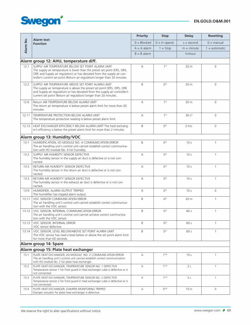
www.swegon.com 89We reserve the right to alter specifications without notice.
EN.GOLD.O&M.001A
larm
No
. Alarm textFunction
Priority Stop Delay Resetting
0 = Blocked 0 = In operat. s = second 0 = manual
A = A alarm 1 = Stop m = minute 1 = automatic
B = B alarm h=hour
Alarm group 12: AHU, temperature diff.12:1 SUPPLY AIR TEMPERATURE BELOW SET POINT ALARM LIMIT
The supply air temperature is lower than the preset set point (ERS, ORS, ORE and Supply air regulation) or has deviated from the supply air con-troller’s current set point (Return air regulation) longer than 20 minutes.
A 13) 20 m 0
12:2 SUPPLY AIR TEMPERATURE ABOVE SET POINT ALARM LIMITThe supply air temperature is above the preset set point (ERS, ORS, ORE and Supply air regulation) or has deviated from the supply air controller’s current set point (Return air regulation) longer than 20 minutes.
B 03) 20 m 0
12:6 Return AIR TEMPERATURE BELOW ALARM LIMITThe return air temperature is below preset alarm limit for more than 20 minutes.
A 13) 20 m 0
12:11 TEMPERATURE PROTECTION BELOW ALARM LIMITThe temperature protection reading is below preset alarm limit.
A 13) 30 s2) 0
12:13 HEAT EXCHANGER EFFICIENCY BELOW ALARM LIMIT The heat exchang-er’s efficiency is below the preset alarm limit for more than 2 minutes.
B 03) 2 hrs. 0
Alarm group 13: Humidity/VOC13:1 HUMIDIFICATION, I/O MODULE NO. 4 COMMUNICATION ERROR
The air handling unit's control unit cannot establish correct communica-tion with I/O module No. 4 for humidity.
B 03) 10 s 1
13:2 SUPPLY AIR HUMIDITY SENSOR DEFECTIVEThe humidity sensor in the supply air duct is defective or is not con-nected.
A 03) 10 s 1
13:3 RETURN AIR HUMIDITY SENSOR DEFECTIVEThe humidity sensor in the return air duct is defective or is not con-nected.
A 03) 10 s 1
13:3 RETURN AIR HUMIDITY SENSOR DEFECTIVE The humidity sensor in the exhaust air duct is defective or is not con-nected.
A 03) 10 s 1
13:9 HUMIDIFIER, ALARM OUTPUT TRIPPEDThe humidifier has tripped alarm output.
A 03) 10 s 0
13:11 VOC SENSOR COMMUNICATION ERRORThe air handling unit's control unit cannot establish correct communica-tion with the VOC sensor.
B 03) 20 m 1
13:12 VOC SENSOR, INTERNAL COMMUNICATION ERRORThe air handling unit's control unit cannot achieve correct communica-tion with the VOC sensor.
B 03) 60 s 1
13:13 VOC SENSOR, INTERNAL ERRORVOC sensor defective.
B 03) 60 s 1
13:14 VOC SENSOR, LEVEL BELOW/ABOVE SET POINT ALARM LIMITThe VOC sensor has read a level below or above the set point alarm limit for more than 60 seconds.
B 03) 60 s 1
Alarm group 14: SpareAlarm group 15: Plate heat exchanger
15:1 PLATE HEAT EXCHANGER, I/O-MODULE NO. 2 COMMUNICATION ERRORThe air handling unit's control unit cannot establish correct communication with I/O module No. 2 for plate heat exchanger.
A 13)4) 10 s 1
15:2 PLATE HEAT EXCHANGER, TEMPERATURE SENSOR NO. 1 DEFECTIVETemperature sensor 1 for frost guard in heat exchanger cube is defective or is not connected.
A 13)4) 3 s 1
15:3 PLATE HEAT EXCHANGER, TEMPERATURE SENSOR NO. 2 DEFECTIVETemperature sensor 2 for frost guard in heat exchanger cube is defective or is not connected.
A 13)4) 3 s 1
15:4 PLATE HEAT EXCHANGER, DAMPER MONITORING TRIPPEDDamper actuator for plate heat exchanger is defective.
A 03)4) 10 m 0

EN.GOLD.O&M.001
90 www.swegon.com We reserve the right to alter specifications without notice.
Ala
rm N
o. Alarm text
Function
Priority Stop Delay Resetting
0 = Blocked 0 = In operat. s = second 0 = manual
A = A alarm 1 = Stop m = minute 1 = automatic
B = B alarm h=hour
15:7 PLATE HEAT EXCHANGER, I/O-MODULE NO. 3 COMMUNICATION ERRORThe air handling unit's control unit cannot establish correct communication with I/O module No. 3 for the plate heat exchanger.
A 13)4) 10 s 1
15:8 PLATE HEAT EXCHANGER, BYPASS DAMPER MONITORING TRIPPEDThe bypass damper monitoring function of the plate heat exchanger has tripped.
A 03)4) 10 m 0
15:9 PLATE HEAT EXCHANGER, DAMPER NO. 1 MONITORING TRIPPEDThe section damper 1 monitoring function of the plate heat exchanger has tripped.
A 03)4) 10 m 0
15:10 PLATE HEAT EXCHANGER, DAMPER NO. 2 MONITORING TRIPPEDThe section damper 2 monitoring function of the plate heat exchanger has tripped.
A 03)4) 10 m 0
15:11 PLATE HEAT EXCHANGER, I/O-MODULE NO. 3 COMMUNICATION ERRORThe air handling unit's control unit cannot establish correct communication with I/O module No. 3 for the plate heat exchanger.
A 13)4) 10 s 1
15:12 PLATE HEAT EXCHANGER, BYPASS DAMPER MONITORING TRIPPEDThe bypass damper monitoring function of the plate heat exchanger has tripped.
A 03)4) 10 m 0
15:13 PLATE HEAT EXCHANGER, COUNTER-FLOW, DEFROSTING PRESSURE OVER ALARM LIMIT There has been a continuous need for full defrosting for 2 hours.
B 13)4) 2 h 0
15:14 PLATE HEAT EXCHANGER, DEFROSTING SENSOR NO. C COMMUNICATION ERRORThe air handling unit’s control unit cannot establish correct communication with defrosting sensor C for the heat exchanger.
B 0 10 m 1
15:15 PLATE HEAT EXCHANGER, DEFROSTING PRESSURE OVER ALARM LIMITThe need for defrosting has been over 95% continuously for 144 minutes.
B 1 2.4 h 0
Alarm group 16: Coil heat exchangers16:1 COIL HEAT EXCHANGER, I/O-MODULE NO. 1 COMMUNICATION ERROR
The air handling unit's control unit cannot establish correct communica-tion with I/O module No. 1 for coil heat exchanger.
A 13)4) 10 s 1
16:2 COIL HEAT EXCHANGER, TEMPERATURE SENSOR DEFECTIVEThe temperature sensor on the coil heat exchanger’s pipework package for the frost guard is defective or is not connected.
A 13)4) 3 s 1
16:3 COIL HEAT EXCHANGER, VALVE MONITORING TRIPPEDValve actuator of the coil heat exchanger is defective.
A 03)4) 10 m 0
16:4 COIL HEAT EXCHANGER, PUMP MONITORING TRIPPEDNo in-service indication from the pump is obtained.
A 13)4) 20 s 0
16:5 COIL HEAT EXCHANGER, I/O-MODULE NO. C COMMUNICATION ERRORThe air handling unit's control unit cannot establish correct communica-tion with I/O module No. C for coil heat exchanger.
A 0 10 s 1
16:6 COIL HEAT EXCHANGER, PRESSURE SENSOR DEFECTIVEPressure sensor for the coil heat exchanger is defective or is not connec-ted.
A 0 10 m 1
16:7 COIL HEAT EXCHANGER, LOW PRESSURE IN FLUID CIRCUITExcessively low pressure in coil heat exchanger's fluid circuit.
A 0 5 m 0
Alarm group 17: Rotary heat exchanger17:1 ROTARY HEAT EXCHANGER, MOTOR CONTROLLER COMMUNICATION
ERRORThe air handling unit’s control unit cannot establish correct communica-tion with the heat exchanger motor controller.
A 13)4) 10 s 1
17:2 ROTARY HEAT EXCHANGER, DEFROSTING PRESSURE SENSOR NO. 7 COMMUNICATION ERRORThe air handling unit’s control unit cannot establish correct communica-tion with the heat exchanger pressure sensor no. 7. Applicable to the defrosting function only.
B 03) 10 s 1

www.swegon.com 91We reserve the right to alter specifications without notice.
EN.GOLD.O&M.001A
larm
No
. Alarm textFunction
Priority Stop Delay Resetting
0 = Blocked 0 = In operat. s = second 0 = manual
A = A alarm 1 = Stop m = minute 1 = automatic
B = B alarm h=hour
17:3 ROTARY HEAT EXCHANGER, DEFROSTING PRESSURE OVER ALARM LIMITThe need for defrosting has been over 95% continuously for 144 minutes.
B 13)4) 2,4 h 0
17:4 ROTARY HEAT EXCHANGER, ROTATION DETECTOR TRIPPED No impulses from the rotation detector are registered with the heat exchanger controller.
A1) 13)4) 3 s 0
17:5 ROTARY HEAT EXCHANGER, MOTOR CONTROLLER OVERCURRENTHeat exchanger motor controller has registered excessively high current supplier to the drive motor.
A1) 13)4) 3 s 0
17:6 ROTARY HEAT EXCHANGER, MOTOR CONTROLLER UNDERVOLTAGELow feed voltage is supplied to the rotary heat exchanger’s motor controller.
A1) 13)4) 3 s 0
17:7 ROTARY HEAT EXCHANGER, MOTOR CONTROLLER OVERVOLTAGEHigh feed voltage is supplied to the rotary heat exchanger's motor controller.
A1) 13)4) 3 s 0
17:8 ROTARY HEAT EXCHANGER, MOTOR CONTROLLER EXCESS TEMPERA-TUREHigh temperature (194°F) inside the heat exchanger’s motor controller.
A1) 13)4) 3 s 0
17:9 ROTARY HEAT EXCHANGER, MOTOR CONTROLLER START UP ERRORDrive motor does not rotate during start up.
A1) 13)4) 3 s 0
Alarm group 18: AYC18:1 AYC, I/O MODULE No. 7 COMMUNICATION ERROR
The air handling unit's control unit cannot establish correct communica-tion with I/O module No. 7 for AYC.
A 03) 10 s 1
18:2 AYC HEATING, TEMPERATURE SENSOR DEFECTIVEHeating temperature sensor is defective or is not connected.
A 03) 3 s 1
18:3 AYC HEATING, VALVE MONITORING TRIPPEDThe heated water valve actuator is defective.
B 03) 10 m 0
18:4 AYC HEATING, PUMP MONITORING TRIPPEDThe heated water pump is defective.
A 03) 20 s 0
18:5 AYC HEATING, TEMPERATURE BELOW SET POINT LIMITHeating water temperature is below preset set point longer than 30 minutes.
A 03) 30 m 0
18:6 AYC HEATING, TEMPERATURE ABOVE SET POINT ALARM LIMIT 5)
Heating water temperature exceeds preset set point longer than 30 minutes.
B 03) 30 m 0
18:9 AYC COOLING, TEMPERATURE SENSOR DEFECTIVETemperature sensor for the AYC function (All Year Comfort) cooling is defective or is not connected.
A 03) 3 s 1
18:10 AYC COOLING, VALVE MONITORING TRIPPEDThe chilled water valve actuator is defective.
B 03) 10 m 0
18:11 AYC COOLING, PUMP MONITORING TRIPPEDThe chilled water pump is defective.
A 03) 20 s 0
18:12 AYC COOLING, TEMPERATURE BELOW SET POINT ALARM LIMITHeating water temperature is below preset set point longer than 30 minutes.
A 03) 30 m 0
18:13 AYC COOLING, TEMPERATURE ABOVE SET POINT ALARM LIMIT 5)
Cooling water temperature exceeds preset set point longer than 30 minutes.
B 03) 30 m 0
Alarm group 19-20: Spare

EN.GOLD.O&M.001
92 www.swegon.com We reserve the right to alter specifications without notice.
Ala
rm N
o. Alarm text
Function
Priority Stop Delay Resetting
0 = Blocked 0 = In operat. s = second 0 = manual
A = A alarm 1 = Stop m = minute 1 = automatic
B = B alarm h=hour
Alarm group 22: SpareAlarm group 24-25: SpareAlarm group 26: Pre-filter
26:1 PRE-FILTER, SUPPLY AIR PRESSURE SENSOR NO. 8 COMMUNICATION ERRORThe air handling unit’s control unit cannot establish correct communica-tion with the sensor of the supply air pre-filter.
B 03) 10 s 1
26:2 PRE-FILTER, SUPPLY AIR FOULEDThe pressure across the supply air pre-filter exceeds the preset alarm limit for more than 10 minutes.
B 03) 10 m 0
26:7 PRE-FILTER, Return AIR PRESSURE SENSOR NO. 9 COMMUNICATION ERRORThe air handling unit's control unit cannot establish correct communica-tion with the sensor of the return air pre-filter.
B 03) 10 s 1
26:8 PRE-FILTER, Return AIR FOULEDThe pressure across the return air pre-filter exceeds the preset alarm limit for more than 10 minutes.
B 03) 10 m 0
Alarm group 27: AHU, internal filters27:1 AHU FILTER, SUPPLY AIR PRESSURE SENSOR NO. 3/4 COMMUNICATION
ERRORThe air handling unit's control unit cannot establish correct communica-tion with the sensor of the AHU supply air filter.
B 03) 10 s 1
27:2 AHU FILTER, SUPPLY AIR FOULEDThe pressure across the AHU supply air filter has exceeded the preset alarm limit for more than 10 minutes.
B 03) 10 m 0
27:7 AHU FILTER, Return AIR PRESSURE SENSOR NO. 3/4 COMMUNICATION ERRORThe air handling unit's control unit cannot establish correct communica-tion with the sensor of the AHU return air filter.
B 03) 10 s 1
27:8 AHU FILTER, Return AIR FOULEDThe pressure across the AHU return air filter has exceeded the preset alarm limit for more than 10 minutes.
B 03) 10 m 0
Alarm group 28: Final filter28:1 END FILTER, SUPPLY AIR PRESSURE SENSOR NO. A COMMUNICATION
ERRORThe air handling unit's control unit cannot establish correct communica-tion with the sensor of the supply air end filter.
B 03) 10 s 1
28:2 END FILTER, SUPPLY AIR, FOULEDThe pressure across the supply air end filter has exceeded the preset alarm limit for more than 10 minutes.
B 03) 10 m 0
Alarm group 29: SpareAlarm group 30: Flow measurement
30:1 AIRFLOW MEASUREMENT, SUPPLY AIR PRESSURE SENSOR NO. 1/2 COM-MUNICATION ERRORThe air handling unit's control unit cannot establish correct communica-tion with the flow pressure sensor in the supply air.
A 13) 10 s 1
30:2 AIRFLOW MEASUREMENT, SUPPLY AIRFLOW BELOW SET POINT ALARM LIMITThe supply airflow has gone below its set point by more that 10%, dur-ing a longer period than 20 minutes.
B 03) 20 m 0

www.swegon.com 93We reserve the right to alter specifications without notice.
EN.GOLD.O&M.001A
larm
No
. Alarm textFunction
Priority Stop Delay Resetting
0 = Blocked 0 = In operat. s = second 0 = manual
A = A alarm 1 = Stop m = minute 1 = automatic
B = B alarm h=hour
30:3 AIRFLOW MEASUREMENT, SUPPLY AIRFLOW ABOVE SET POINT ALARM LIMITThe supply airflow has exceeded its set point by more that 10%, during a longer period than 20 minutes.
B 03) 20 m 0
30:6 AIRFLOW MEASUREMENT, Return AIR PRESSURE SENSOR NO. 1/2 COM-MUNICATION ERRORThe air handling unit's control unit cannot establish correct communica-tion with the flow pressure sensor in the return air.
A 13) 10 s 1
30:7 AIRFLOW MEASUREMENT,Return AIRFLOW BELOW SET POINT ALARM LIMITThe return airflow has gone below its set point by more that 10%, dur-ing a longer period than 20 minutes.
B 03) 20 m 0
30:8 AIRFLOW MEASUREMENT, Return AIRFLOW ABOVE SET POINT ALARM LIMITThe return airflow has exceeded its set point by more that 10%, during a longer period than 20 minutes.
B 03) 20 m 0
30:11 AIRFLOW MEASUREMENT, PURGING PRESSURE SENSOR NO. B COM-MUNICATION ERRORThe air handling unit's control unit cannot establish correct communica-tion with the sensor of the rotary heat exchanger purging sector.
B 03) 10 s 1
Alarm group 31: Pressure regulation31:1 PRESSURE REGULATION, SUPPLY AIR PRESSURE SENSOR NO. 5 COM-
MUNICATION ERRORThe air handling unit's control unit cannot establish correct communi-cation with the duct pressure sensor in the supply air. Applies only to pressure regulation of the supply air.
A 13) 10 s 1
31:2 PRESSURE REGULATION, SUPPLY AIR PRESSURE BELOW SET POINT ALARM LIMITThe duct pressure has gone below its set point by more that 10%, dur-ing a longer period than 20 minutes ( if pressure sensors are connected).
B 03) 20 m 0
31:3 PRESSURE REGULATION, SUPPLY AIR PRESSURE ABOVE SET POINT ALARM LIMITThe supply air duct pressure has exceeded its set point by more that 10%, during a longer period than 20 minutes (if pressure sensors are connected).
B 03) 20 m 0
31:6 PRESSURE REGULATION, Return AIR PRESSURE SENSOR NO. 6 COMMU-NICATION ERRORThe air handling unit's control unit cannot establish correct communi-cation with the duct pressure sensor in the return air. Applies only to pressure regulation of the return air.
A 13) 10 s 1
31:7 PRESSURE REGULATION, Return AIR PRESSURE BELOW SET POINT ALARM LIMITThe return air duct pressure has gone below its set point by more that 10%, during a longer period than 20 minutes (if pressure sensors are connected).
B 03) 20 m 0
31:8 PRESSURE REGULATION, Return AIR PRESSURE ABOVE SET POINT ALARM LIMITThe return air duct pressure has exceeded its set point by more that 10%, during a longer period than 20 minutes (if pressure sensors are connected).
B 03) 20 m 0
Alarm group 32: ReCO2/Intermittent night heating32:1 ReCO2, I/O MODULE NO. 0 COMMUNICATION ERROR
The air handling unit's control unit cannot establish correct communica-tion with I/O module no. 0.
A 03) 10 s 1
32:2 ReCO2, PRESSURE SENSOR NO. 0 COMMUNICATION ERRORThe air handling unit's control unit cannot establish correct communica-tion with the pressure sensor.
A 03) 10 s 1

EN.GOLD.O&M.001
94 www.swegon.com We reserve the right to alter specifications without notice.
Ala
rm N
o. Alarm text
Function
Priority Stop Delay Resetting
0 = Blocked 0 = In operat. s = second 0 = manual
A = A alarm 1 = Stop m = minute 1 = automatic
B = B alarm h=hour
32:3 ReCO2/INTERMITTENT NIGHT HEATING, RECIRCULATED AIR DAMPER MONITORING TRIPPEDThe damper actuator does not move to the right position. The position-confirming output signal from the damper is not the same as the input control signal.
B 03) 10 m 0
32:4 ReCO2, OUTDOOR AIR DAMPER MONITORING TRIPPEDThe damper actuator does not move to the right position. The position-confirming output signal from the damper is not the same as the input control signal.
B 03) 10 m 0
Alarm group 33: Service33:1 PERIOD BETWEEN SERVICING PAST ALARM LIMIT
The preset service period has expired.If the alarm is RESET via the hand-held terminal, the alarm will be initi-ated again after 7 days. A new service period can be set and reset under ALARM SETTINGS.
B 03) 5 s 2) 0
33:15 LOCK FUNCTION TRIPPEDContact Swegon or their representative.
– – – 06)
Alarm group 34: External controls34:1 EXTERNAL CONTROL, I/O MODULE NO. 3 COMMUNICATION ERROR
The air handling unit's control unit cannot establish correct communica-tion with I/O module No. 3 for external control.
B 03) 10 s 1
34:2 EXTERNAL CONTROL, I/O MODULE NO. 6 COMMUNICATION ERRORThe air handling unit's control unit cannot establish correct communica-tion with I/O module No. 6 for external control.
B 03) 10 s 1
Alarm group 35: Booster diffusers35:1 BOOSTER AIR TERMINALS, I/O MODULE NO. 8 COMMUNICATION ER-
RORThe air handling unit's control unit cannot establish correct communica-tion with I/O module No. 8 for Booster diffusers.
B 03) 10 s 1
Alarm group 36: External communication, I/O-modules36:1 EXTERNAL COMMUNICATION, I/O MODULE NO. A COMMUNICATION
ERRORThe air handling unit’s control unit cannot establish correctcommunication with I/O module No. A.
B 03) 10 s 1
36:2 EXTERNAL COMMUNICATION, I/O MODULE NO. A TEMPERATURESENSOR NO. 1 DEFECTIVEI/O-module A, temperature sensor 1, is defective or is notconnected.
B 03) 3 s 1
36:3 EXTERNAL COMMUNICATION, I/O MODULE NO. A TEMPERATURESENSOR NO. 2 DEFECTIVEI/O-module A, temperature sensor 2, is defective or is notconnected
B 03) 3 s 1
36:6 EXTERNAL COMMUNICATION, I/O MODULE NO. B COMMUNICATIONERRORThe air handling unit’s control unit cannot establish correctcommunication with I/O module No. B.
B 03) 10 s 1
36:7 EXTERNAL COMMUNICATION, I/O MODULE NO. B TEMPERATURESENSOR NO. 1 DEFECTIVEI/O-module B, temperature sensor 1, is defective or is notconnected.
B 03) 3 s 1
36:8 EXTERNAL COMMUNICATION, I/O MODULE NO. B TEMPERATURESENSOR NO. 2 DEFECTIVEI/O-module B, temperature sensor 2, is defective or is notconnected.
B 03) 3 s 1

www.swegon.com 95We reserve the right to alter specifications without notice.
EN.GOLD.O&M.001A
larm
No
. Alarm textFunction
Priority Stop Delay Resetting
0 = Blocked 0 = In operat. s = second 0 = manual
A = A alarm 1 = Stop m = minute 1 = automatic
B = B alarm h=hour
36:11 EXTERNAL COMMUNICATION, I/O MODULE NO. C COMMUNICATIONERRORThe air handling unit’s control unit cannot establish correctcommunication with I/O module No. C.
B 03) 10 s 1
36:12 EXTERNAL COMMUNICATION, I/O MODULE NO. C TEMPERATURESENSOR NO. 1 DEFECTIVEI/O-module C, temperature sensor 1, is defective or is notconnected.
B 03) 3 s 1
36:13 EXTERNAL COMMUNICATION, I/O MODULE NO. C TEMPERATURESENSOR NO. 2 DEFECTIVEI/O-module C, temperature sensor 2, is defective or is notconnected.
B 03) 3 s 1
Alarm group 37: SpareAlarm group 49-54: Supply air fan no. 1A-3B 8)
49-54:1 SUPPLY AIR FAN 1-3/A-B COMMUNICATION ERRORThe air handling unit's control unit cannot establish correct communica-tion with the supply air fan motor controller.
A 13) 10 s 1
49-54:2 SUPPLY AIR FAN 1-3/A-B MOTOR CONTROLLER OVERCURRENTHigh current supplied to motor
A1) 13) 10 s 0
49-54:3 SUPPLY AIR FAN 1-3/A-B MOTOR CONTROLLER UNDERVOLTAGEVoltage below the normal level is supplied.
A1) 13) 10 s 0
49-54:4 SUPPLY AIR FAN 1-3/A-B MOTOR CONTROLLER OVERVOLTAGEExcessively high voltage is supplied.
A1) 13) 10 s 0
49-54:5 SUPPLY AIR FAN 1-3/A-B MOTOR CONTROLLER EXCESS TEMPERATUREHigh internal temperature.
A1) 13) 10 s 0
49-54:6
SUPPLY AIR FAN 1-3/A-B MOTOR CONTROL START UP ERRORSupply air fan does not rotate on a start up, rotates in wrong direction or rotates at excessively high speed.
A1) 13) 10 s 0
49-54:7 SUPPLY AIR FAN 1-3/A-B MOTOR CONTROLLER UNEVEN PHASE VOLT-AGEHigh voltage difference between the phases (3-phase, 400 V), which causes rippling.
A1) 13) 10 s 1
49-54:8 SUPPLY AIR FAN 1-3/A-B MOTOR CONTROLLER PHASE FAILUREPhase failure in motor controller.
A1) 13) 10 s 1
49-54:9 SUPPLY AIR FAN 1-3/A-B MOTOR CONTROLLER MEMORY ERRORInternal memory error in motor controller.
A1) 13) 10 s 1
49-54:10
SUPPLY AIR FAN 1-3/A-B MOTOR CONTROLLER CURRENT LIMITATIONCurrent/Voltage limitation in motor controller.
B 03) 60 s 1
49-51:11
SUPPLY AIR FAN 1A-3A MOTOR CONTROLLER INTERNAL COMMUNICA-TION ERRORInternal communication error in motor controller.
A 13) 10 s 1
Alarm group 55-60: Return air fan no. 1A-3B 9)
55-60:1 Return AIR FAN 1-3/A-B COMMUNICATION ERRORThe air handling unit's control unit cannot establish correct communica-tion with the return air fan motor controller.
A 13) 10 s 1
55-60:2 Return AIR FAN 1-3/A-B MOTOR CONTROLLER OVERCURRENTHigh current supplied to motor
A1) 13) 3 s 0
55-60:3 Return AIR FAN 1-3/A-B MOTOR CONTROLLER UNDERVOLTAGEVoltage below the normal level is supplied.
A1) 13) 3 s 0
55-60:4 Return AIR FAN 1-3/A-B MOTOR CONTROLLER OVERCURRENTExcessively high voltage is supplied.
A1) 13) 3 s 0

EN.GOLD.O&M.001
96 www.swegon.com We reserve the right to alter specifications without notice.
Ala
rm N
o. Alarm text
Function
Priority Stop Delay Resetting
0 = Blocked 0 = In operat. s = second 0 = manual
A = A alarm 1 = Stop m = minute 1 = automatic
B = B alarm h=hour
55-60:5 Return AIR FAN 1-3/A-B MOTOR CONTROLLER EXCESS TEMPERATUREHigh internal temperature.
A1) 13) 3 s 0
55-60:6
Return AIR FAN 1-3/A-B MOTOR CONTROLLER START UP ERRORReturn air fan does not rotate on a start up, rotates in wrong direction or rotates at excessively high speed.
A1) 13) 3 s 0
55-60:7
Return AIR FAN 1-3/A-B MOTOR CONTROLLER UNEVEN PHASE VOLTAGEHigh voltage difference between the phases (3-phase, 400 V), which causes rippling.
A1) 13) 5 s 1
55-60:8 Return AIR FAN 1-3/A-B MOTOR CONTROLLER PHASE FAILUREPhase failure in motor controller.
A1) 13) 5 s 1
55-60:9 ETRACT AIR FAN 1-3/A-B MOTOR CONTROLLER MEMORY ERRORInternal memory error in motor controller.
A1) 13) 5 s 1
55-60:10
Return AIR FAN 1-3/A-B MOTOR CONTROLLER CURRENT LIMITATIONCurrent/Voltage limitation in motor controller.
B 03) 60 s 1
55-57:11
Return AIR FAN 1A-3A MOTOR CONTROLLER INTERNAL COMMUNICA-TION ERRORInternal communication error in motor controller.
A 13) 5 s 1
Alarm group 61: Supply air fan, I/O module
61:1 SUPPLY AIR FAN NO. 1A I/O MODULE COMMUNICATION ERRORThe air handling unit's control unit cannot establish correct communica-tion with supply air fan no. 1A I/O module.
A 13) 10 s 1
61:6 SUPPLY AIR FAN NO. 2A I/O MODULE COMMUNICATION ERRORThe air handling unit's control unit cannot establish correct communica-tion with supply air fan no. 2A I/O module.
A 13) 10 s 1
61:11 SUPPLY AIR FAN NO. 3A I/O MODULE COMMUNICATION ERRORThe air handling unit's control unit cannot establish correct communica-tion with supply air fan no. 3A I/O module.
A 13) 10 s 1
Alarm group 62: Return air fan, I/O module
62:1 Return AIR FAN NO. 1A I/O MODULE COMMUNICATION ERRORThe air handling unit's control unit cannot establish correct communica-tion with return air fan no. 1A I/O module.
A 13) 10 s 1
62:6 Return AIR FAN NO. 2A I/O MODULE COMMUNICATION ERRORThe air handling unit's control unit cannot establish correct communica-tion with return air fan no. 2A I/O module.
A 13) 10 s 1
62:11 Return AIR FAN NO. 3A I/O MODULE COMMUNICATION ERRORThe air handling unit's control unit cannot establish correct communica-tion with return air fan no. 3A I/O module.
A 13) 10 s 1
1) Cannot be blocked.2) The delay is adjustable.3) Adjustable.4) Stops the AHU if the temperature is below the adjustable limit.5) Inactive as factory setting.6) Contact Swegon or their representative.7) Alarm group 38 = MIRU Control 1. Alarm group 39 = MIRU Control 2. Alarm group 40 = MIRU Control 3. Alarm group 41 = MIRU Control 4. Alarm group 42 = MIRU Control 5. Alarm group 43 = MIRU Control 6. Alarm group 44 = MIRU Control 7. Alarm group 45 = MIRU Control 8. Alarm group 46 = MIRU Control 9. Alarm group 47 = MIRU Control 10.8) Alarm group 49 = Supply air fan 1A. Alarm group 50 = Supply air fan 2A. Alarm group 51 = Supply air fan 3A. Alarm group 52 = Supply air fan 1B. Alarm group 53 = Supply air fan 2B. Alarm group 54 = Supply air fan 3B.9) Alarm group 55 = Extrat air fan 1A. Alarm group 56 = Extrat air fan 2A. Alarm group 57 = Extrat air fan 3A. Alarm group 58 = Extrat air fan 1B. Alarm group 59 = Extrat air fan 2B. Alarm group 60 = Extrat air fan 3B.
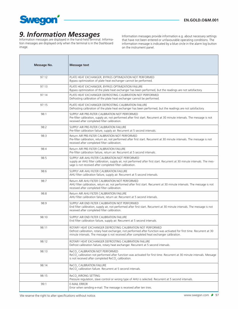
www.swegon.com 97We reserve the right to alter specifications without notice.
EN.GOLD.O&M.001
9. Information MessagesInformation messages are displayed in the hand-held terminal. Informa-tion messages are displayed only when the terminal is in the Dashboard image.
Message No. Message text
97:12 PLATE HEAT EXCHANGER, BYPASS OPTIMIZATION NOT PERFORMEDBypass optimization of plate heat exchanger cannot be performed.
97:13 PLATE HEAT EXCHANGER, BYPASS OPTIMIZATION FAILUREBypass optimization of the plate heat exchanger has been performed, but the readings are not satisfactory.
97:14 PLATE HEAT EXCHANGER DEFROSTING CALIBRATION NOT PERFORMEDDefrosting calibration of the plate heat exchanger cannot be performed.
97:15 PLATE HEAT EXCHANGER DEFROSTING CALIBRATION FAILUREDefrosting calibration of the plate heat exchanger has been performed, but the readings are not satisfactory.
98:1 SUPPLY AIR PRE-FILTER CALIBRATION NOT PERFORMEDPre-filter calibration, supply air, not performed after first start. Recurrent at 30 minute intervals. The message is not received after completed filter calibration.
98:2 SUPPLY AIR PRE-FILTER CALIBRATION FAILUREPre-filter calibration failure, supply air. Recurrent at 5 second intervals.
98:3 Return AIR PRE-FILTER CALIBRATION NOT PERFORMEDPre-filter calibration, return air, not performed after first start. Recurrent at 30 minute intervals. The message is not received after completed filter calibration.
98:4 Return AIR PRE-FILTER CALIBRATION FAILUREPre-filter calibration failure, return air. Recurrent at 5 second intervals.
98:5 SUPPLY AIR AHU FILTER CALIBRATION NOT PERFORMEDsupply air AHU filter calibration, supply air, not performed after first start. Recurrent at 30 minute intervals. The mes-sage is not received after completed filter calibration.
98:6 SUPPLY AIR AHU FILTER CALIBRATION FAILUREAHU filter calibration failure, supply air. Recurrent at 5 second intervals.
98:7 Return AIR AHU FILTER CALIBRATION NOT PERFORMEDAHU filter calibration, return air, not performed after first start. Recurrent at 30 minute intervals. The message is not received after completed filter calibration.
98:8 Return AIR AHU FILTER CALIBRATION FAILUREAHU filter calibration failure, return air. Recurrent at 5 second intervals.
98:9 SUPPLY AIR END FILTER CALIBRATION NOT PERFORMEDEnd filter calibration, supply air, not performed after first start. Recurrent at 30 minute intervals. The message is not received after completed filter calibration.
98:10 SUPPLY AIR END FILTER CALIBRATION FAILUREEnd filter calibration failure, supply air. Recurrent at 5 second intervals.
98:11 ROTARY HEAT EXCHANGER DEFROSTING CALIBRATION NOT PERFORMEDDefrost calibration, rotary heat exchanger, not performed after function was activated for first time. Recurrent at 30 minute intervals. The message is not received after completed heat exchanger calibration.
98:12 ROTARY HEAT EXCHANGER DEFROSTING CALIBRATION FAILUREDefrost calibration failure, rotary heat exchanger. Recurrent at 5 second intervals.
98:13 ReCO2 CALIBRATION NOT PERFORMEDReCO2 calibration not performed after function was activated for first time. Recurrent at 30 minute intervals. Message is not received after completed ReCO2 calibration.
98:14 ReCO2 CALIBRATION FAILUREReCO2 calibration failure. Recurrent at 5 second intervals.
98:15 ReCO2 WRONG SETTINGPressure regulation, slave control or wrong type of AHU is selected. Recurrent at 5 second intervals.
99:1 E-MAIL ERRORError when sending e-mail. The message is received after ten tries.
Information messages provide information e.g. about necessary settings that have not been entered or unfavourable operating conditions. The information message is indicated by a blue circle in the alarm log button on the instrument panel.

EN.GOLD.O&M.001
98 www.swegon.com We reserve the right to alter specifications without notice.
Ala
rm N
o. Alarm text
Function
99:5 FTP ERRORError when sending to ftp. The message is received after ten tries.
99:7 SD SHORT MEMORY SOON FULLThe SD card's memory is soon full. The oldest log data will sonn be deleted.
99:8 SD SHORT MEMORY FULLThe SD card's memory is full. The oldest log data is being deleted.
99:14 INTERNAL SERIAL MEMORY ERROR CPEx1Internal serial memory error CPEx1
99:15 CLOCK CIRCUIT DEFECTIVECircuit for the clock is defective

www.swegon.com 99We reserve the right to alter specifications without notice.
EN.GOLD.O&M.001
16"0.6" 2"*
2" 2"
GOLD GOLD
0.5"
4" 4"2"2" 2"2"
M
4"
M
4"
0.5"
16"0.6"
GOLD GOLD
0.5"
4" 4"
2"*
2"2"2"2" 2"2"
M
4"M
4"
0.5"
10. Technical Data10.1 Dimensions, GOLD RX one-piece air handling unit with rotary heat exchangerGOLD 05, 07/08
GOLD 11/12
* The air handling unit is supplied without end connection panel if a duct accessory housed in an insulated casing will be connected.
Size A B C D F G H J K L Weight, lb
05 29.53 32.48 22.09 13.58 12 18 36.22 2.26 7.24 4.53 534.6
07 31.50 39.17 28.74 17.32 14 24 42.72 2.02 7.59 4.04 662.2
08 31.50 39.17 28.74 17.32 14 24 42.72 2.02 7.59 4.04 679.8
11 25.79 47.20 36.81 21.65 18 32 50.98 1.92 7.60 3.84 1091.2
12 25.79 47.20 36.81 21.65 18 32 50.98 1.92 7.60 3.84 1139.6
Size A B C D F G H J K L Weight, kg
05 750.00 825.00 561.00 345.00 300 450 920.00 57.50 187.50 114.99 243.0
07 800.00 995.00 730.00 440.00 350 600 1085.00 51.27 197.50 102.54 301.0
08 800.00 995.00 730.00 440.00 350 600 1085.00 51.27 197.50 102.54 309.0
11 655.00 1199.00 935.00 550.00 450 800 1295.00 48.72 199.50 97.45 496.0
12 655.00 1199.00 935.00 550.00 450 800 1295.00 48.72 199.50 97.45 518.0
* The air handling unit is supplied without end connection panel if a duct accessory housed in an insulated casing will be connected.
Base beams are optional.
Imperial
Metric

EN.GOLD.O&M.001
100 www.swegon.com We reserve the right to alter specifications without notice.
* The air handling unit is supplied without end connection panel if a duct accessory housed in an insulated casing will be connected.
The dimension print shows the connection configuration for fan arrangement 1. For fan arrangement 2 the connections are mirror-inverted.
E
M
M
16"
GOLD GOLD
0.5"
4"
2"2" 2"
2" 2"
4"
4"
0.5"
1" 2"*
1"
2"
4"
GOLD 14/20, 25/30
* The air handling unit is supplied without end connection panel if a duct accessory housed in an insulated casing will be connected.
The dimension print shows the connection configuration for fan arrangement 1. For fan arrangement 2 the connections are mirror-inverted.
M
M
GOLD GOLD
0.5"
4"
2" 2"2" 2"
2" 2"
4"
2"*
1"
1"
1"
GOLD 35/40
GOLD 50/60 GOLD 70/80
GOLD
GOLD
1"
1"
1" 1" 3"4"
3"
1"*
Size A B C D E F G H I J K L M Weight, lb
14 30.12 55.12 44.72 21.65 8.19 16 40 54.92 11.73 4.29 7.87 81.89 7.40 1295.8
20 30.12 55.12 44.72 21.65 8.19 16 40 54.92 11.73 4.29 7.87 81.89 7.40 1375.0
25 32.87 62.99 52.60 21.65 7.60 20 48 62.80 11.73 3.70 7.87 87.40 7.99 1641.2
30 32.87 62.99 52.60 21.65 7.60 20 48 62.80 11.73 3.70 7.87 87.40 7.99 1729.2
35 37.32 78.35 67.95 21.65 7.87 24 56 78.15 15.43 6.02 11.61 96.30 9.45 2354.0
40 37.32 78.35 67.95 21.65 7.87 24 56 78.15 15.43 6.02 11.61 96.30 9.45 2464.0
50 41.34 91.26 22.44 5.91 32 64 88.70 16.65 4.53 14.17 105.12 3121.8
60 41.34 91.26 22.44 5.91 32 64 88.70 16.65 4.53 14.17 105.12 3295.6
70 50.20 103.82 22.44 6.46 40 72 103.94 12.56 6.34 16.50 122.83 4864.2
80 50.20 103.82 22.44 6.46 40 72 103.94 12.56 6.34 16.50 122.83 5357.0
* The air handling unit is supplied without end connection panel if a duct accessory housed in an insulated casing will be connected.
GOLD
GOLD
1"
1"
1"5" 1"
4"4"
3" 3"
2"*
2"
Imperial

www.swegon.com 101We reserve the right to alter specifications without notice.
EN.GOLD.O&M.001
Size A B C D E F G H I J K L M Weight, kg
14 765 1400 1136 550 208 400 1000 1395 298 109 200 2080 188 589
20 765 1400 1136 550 208 400 1000 1395 298 109 200 2080 188 625
25 835 1600 1336 550 193 500 1200 1595 298 94 200 2220 203 746
30 835 1600 1336 550 193 500 1200 1595 298 94 200 2220 203 786
35 948 1990 1726 550 200 600 1400 1985 392 153 295 2446 240 1070
40 948 1990 1726 550 200 600 1400 1985 392 153 295 2446 240 1120
50 1050 2318 - 570 150 800 1600 2253 423 115 360 2670 - 1419
60 1050 2318 - 570 150 800 1600 2253 423 115 360 2670 - 1498
70 1275 2637 - 570 164 1000 1800 2640 319 161 419 3120 - 2211
80 1275 2637 - 570 164 1000 1800 2640 319 161 419 3120 - 2435
GOLD 100
Size A B D E F G H I J K L M N O P Weight, lb
100 44.33 131.50 42.13 7.52 48 96 135.43 20.47 8.27 18.50 130.79 31.50 6.69 98.43 67.72 8580.0
Size A B D E F G H I J K L M N O P Weight, kg
100 1126 3340 1070 191 1200 2400 3440 520 210 470 3322 800 170 2500 1720 3900
N OM
N
P
P
GOLD
GOLD
GOLD
1"
1"2"
2"*
2"4"4" 42"
127"
42"40"
3"3"
5"
1"
* The air handling unit is supplied without end connection panel if a duct accessory housed in an insulated casing will be connected.
Imperial
Metric
Metric

EN.GOLD.O&M.001
102 www.swegon.com We reserve the right to alter specifications without notice.
D
E E
GOLD GOLD
GOLD
NN
0.5"
4"
4"
3"3"
4"2"2"2"
2"2"2"
2"*16"
1"
4"
0.5"
10.2 Dimensions, GOLD PX one-piece air handling unit with plate heat exchanger
GOLD 05, 07/08 GOLD 11/12
GOLDGOLD
0.5" 0.5"
4" 4"
7"
3"
2" 2"
1"
2"
3"
1"
1"
2"
2"*
NN
16"
* The air handling unit is supplied without end connection panel if a duct accessory housed in an insulated casing will be connected.
* The air handling unit is supplied without end connection panel if a duct accessory housed in an insulated casing will be connected.
D
E E
M M
N
GOLD GOLD
1" 2"*
2" 2"2"
3"
4"
4"
0.5"
2"
16"
1"
* The air handling unit is supplied without end connection panel if a duct accessory housed in an insulated casing will be connected.
GOLD 14/20, 25/30
Size A B C D E F G H I J K L M N Weight, lb
05 31.50 32.48 - 13.58 - 12 18 36.22 4.53 2.26 7.24 78.74 - 2.26 741.4
07 36.02 39.17 - 17.32 - 14 24 42.72 4.04 2.02 7.59 87.80 - 2.02 921.8
08 36.02 39.17 - 17.32 - 14 24 42.72 4.04 2.02 7.59 87.80 - 2.02 941.6
11 25.79 47.20 36.81 47.24 15.63 18 32 50.98 3.84 1.92 7.60 98.82 - 1.92 1421.2
12 25.79 47.20 36.81 47.24 15.63 18 32 50.98 3.84 1.92 7.60 98.82 - 1.92 1469.6
14 30.12 55.12 44.72 51.18 17.72 16 40 54.92 11.92 7.52 7.56 111.42 8.19 4.36 1700.6
20 30.12 55.12 44.72 51.18 17.72 16 40 54.92 11.92 7.52 7.56 111.42 8.19 4.36 1779.8
25 32.87 62.99 52.60 61.02 22.64 20 48 62.80 11.92 8.12 7.50 126.77 7.60 3.76 2327.6
30 32.87 62.99 52.60 61.02 22.64 20 48 62.80 11.92 8.12 7.50 126.77 7.60 3.76 2415.6
Size A B C D E F G H I J K L M N Weight, kg
05 800 825 - 345 - 300 450 920 115 57 184 2000 - 57 337
07 915 995 - 440 - 350 600 1085 103 51 193 2230 - 51 419
08 915 995 - 440 - 350 600 1085 103 51 193 2230 - 51 428
11 655 1199 935 1200 397 450 800 1295 97 49 193 2510 - 49 646
12 655 1199 935 1200 397 450 800 1295 97 49 193 2510 - 49 668
14 765 1400 1136 1300 450 400 1000 1395 303 191 192 2830 208 111 773
20 765 1400 1136 1300 450 400 1000 1395 303 191 192 2830 208 111 809
25 835 1600 1336 1550 575 500 1200 1595 303 206 190 3220 193 96 1058
30 835 1600 1336 1550 575 500 1200 1595 303 206 190 3220 193 96 1098
Imperial
Metric

www.swegon.com 103We reserve the right to alter specifications without notice.
EN.GOLD.O&M.001
Size L B H A C D E F G I J Weight, lb
05 43.27 32.48 19.29 36.89 6.38 12 18 4.02 22.09 7.24 3.65 261.8
07 46.22 39.17 22.64 39.84 6.38 14 24 2.87 28.74 7.59 4.32 292.6
08 46.22 39.17 22.64 39.84 6.38 14 24 2.87 28.74 7.59 4.32 301.4
L1GF 6"1" 1"
L2E D
A2" 2" 2" 2"2"*
2"*4"
4"
GOLD GOLD
B
H
0.5"
F
J
G
L1GF 6"1" 1"
L2E D
A2" 2" 2" 2"2"*
2"*4"
4"
GOLD GOLD
B
H
0.5"
F
J
G
LA C1" 1"
2"*F 2" 2"GF
0.5"B B
H
0.5"
4"
GOLDF
J
G
F
J
G
GOLD 11/12
10.3 Dimensions, separate GOLD SD supply air and return air handling unitsGOLD 05, 07/08
Size L B H A C D E F G I J Weight, kg
05 1099 825 490 937 162 300 450 102 561 187.5 95 119
07 1174 995 575 1012 162 350 600 73 730 197.5 112.5 133
08 1174 995 575 1012 162 350 600 73 730 197.5 112.5 137
Size L1 L2 B H A D E F G I J K L
11 1404 2092 1199 648 935 740 1352 540 650 199.5 99 450 800
12 1404 2092 1199 648 935 740 1352 540 650 199.5 99 450 800
Size L1 L2 B H A D E F G I J K L
11 55.28 82.36 47.20 25.51 36.81 29.13 53.23 21.26 25.59 7.85 3.90 18 32
12 55.28 82.36 47.20 25.51 36.81 29.13 53.23 21.26 25.59 7.85 3.90 18 32
Size Weight, kg fan + filter
Weight, kg fan + filter + coil
11 176 347
12 187 358
Size Weight, lb fan + filter
Weight, lb fan + filter + coil
11 387 763
12 411 788
* If a duct accessory housed in an insulated casing will be con-nected, the air handling unit is supplied with an end connection panel designed for connection to the duct accessory.
* The air handling unit is supplied without end connection panel if a duct accessory housed in an insulated casing will be connected.** Width of coil heat exchanger (if required) = B + 200 mm.
Fan Fan + Coil heat exchanger
Base beams are optional.
Imperial
Metric
Imperial
Metric

EN.GOLD.O&M.001
104 www.swegon.com We reserve the right to alter specifications without notice.
1"1"
1"
8"F E
L1
CL2
E D CL3
2" 2"*2" A 2"
0.5"
1"
BGI
FH
J
J
4"
GOLD GOLD GOLD
1"1"
1"
8"F E
L1
CL2
E D CL3
2" 2"*2" A 2"
0.5"
1"
BGI
FH
J
J
4"
GOLD GOLD GOLD
GOLD 25/30, 35/40
Size Weight, lb fan
Weight, lb fan + filter
Weight, lb fan + filter + coil
25/30 587.4 840.4 1491.6
35/40 770.0 1069.2 1894.2
Size Weight, kg fan
Weight, kg fan + filter
Weight, kg fan + filter + coil
25/30 267 382 678
35/40 350 486 861
Size L1 L2 L3 B H A C D E F G I J
25/30 1145 1980 2720 1600 1026 1336 1093 740 887 500 1200 200 263
35/40 1145 1980 2720 1990 1126 1726 1093 740 887 600 1400 295 263
Size L1 L2 L3 B H A C D E F G I J
25/30 45.08 77.95 107.09 62.99 40.39 52.60 43.03 29.13 34.92 20 48 7.87 10.35
35/40 45.08 77.95 107.09 78.35 44.33 67.95 43.03 29.13 34.92 24 56 11.61 10.35
Fan Fan + filter Fan + filter + coil heat exchanger
* If a duct accessory housed in an insulated casing will be connected, the air handling unit is supplied with an end connection panel designed for connection to the duct accessory.
** Width of coil heat exchanger (if required) = B + 200 mm
1"1"
1"
8"F E
L1
CL2
E D CL30.5"
F H
J
1"
J
BGI
4"2" 2"*2" A 2"
GOLD GOLD GOLD
1"1"
1"
8"F E
L1
CL2
E D CL30.5"
F H
J
1"
J
BGI
4"2" 2"*2" A 2"
GOLD GOLD GOLD
GOLD 14/20
Size Weight, lb fan Weight, lb fan + filter
Weight, lb fan + filter + coil
14/20 413.6 642.4 1139.6
Size Weight, kg fan Weight, kg fan + filter
Weight, kg fan + filter + coil
14/20 188 292 518
Size L1 L2 L3 B H A C D E F G I J
14/20 40.94 73.82 102.95 55.12 31.73 44.72 38.90 29.13 34.92 16 40 7.87 7.99
Size L1 L2 L3 B H A C D E F G I J
14/20 1040 1875 2615 1400 806 1136 988 740 887 400 1000 200 203
Fan Fan + filter Fan + filter + coil heat exchanger
* The air handling unit is supplied without end connection panel if a duct accessory housed in an insulated casing will be connected.** Width of coil heat exchanger (if required) = B + 200 mm
Imperial
Imperial
Metric
Metric
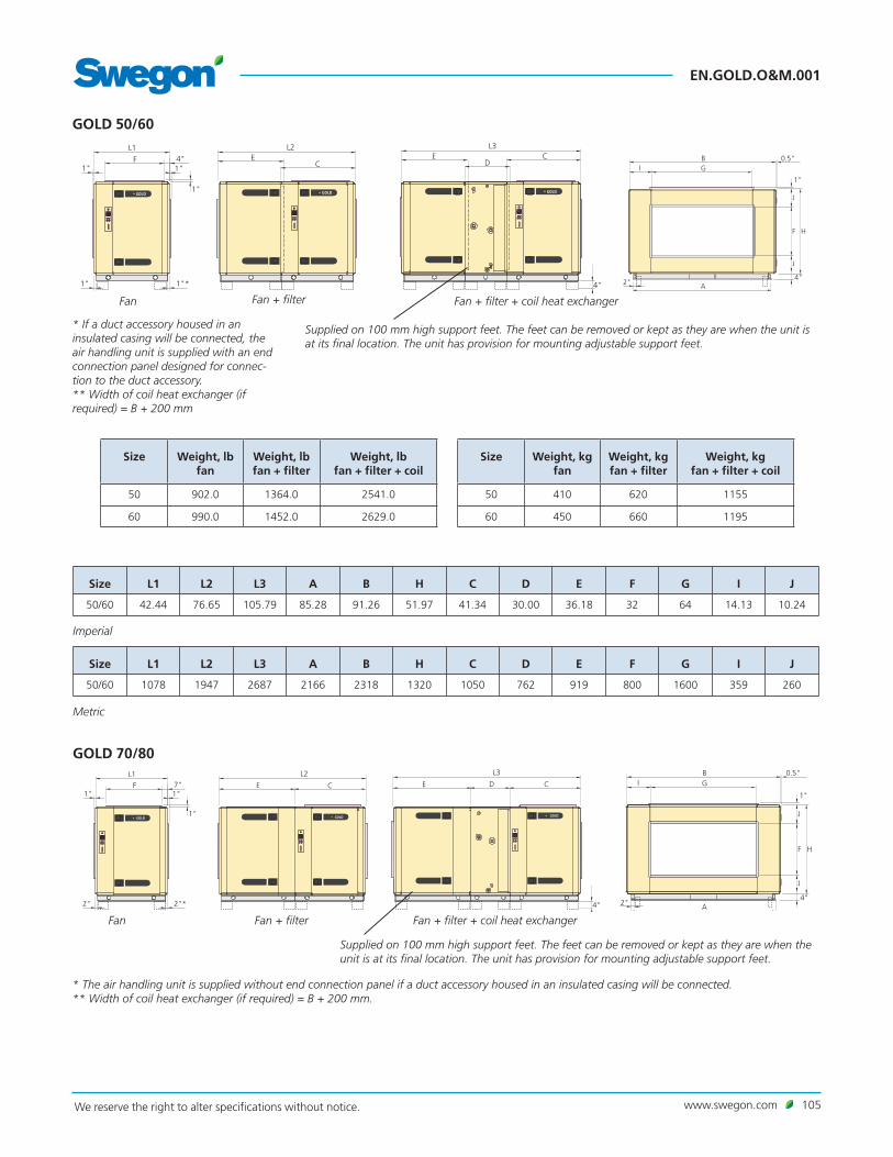
www.swegon.com 105We reserve the right to alter specifications without notice.
EN.GOLD.O&M.001
1"1"
1"
4"F EC
L1 L2E C
D
L3
1" 1"* 4"2" A
0.5"
1"
BGI
F H
J
J
4"
GOLD GOLD GOLD
1"1"
1"
4"F EC
L1 L2E C
D
L3
1" 1"* 4"2" A
0.5"
1"
BGI
F H
J
J
4"
GOLD GOLD GOLD
GOLD 50/60
Size Weight, lb fan
Weight, lb fan + filter
Weight, lb fan + filter + coil
50 902.0 1364.0 2541.0
60 990.0 1452.0 2629.0
Size Weight, kg fan
Weight, kg fan + filter
Weight, kg fan + filter + coil
50 410 620 1155
60 450 660 1195
Size L1 L2 L3 A B H C D E F G I J
50/60 42.44 76.65 105.79 85.28 91.26 51.97 41.34 30.00 36.18 32 64 14.13 10.24
Size L1 L2 L3 A B H C D E F G I J
50/60 1078 1947 2687 2166 2318 1320 1050 762 919 800 1600 359 260
Fan Fan + filter Fan + filter + coil heat exchanger
* If a duct accessory housed in an insulated casing will be connected, the air handling unit is supplied with an end connection panel designed for connec-tion to the duct accessory.** Width of coil heat exchanger (if required) = B + 200 mm
Supplied on 100 mm high support feet. The feet can be removed or kept as they are when the unit is at its final location. The unit has provision for mounting adjustable support feet.
Imperial
Metric
1"1"
1"
7"F E C
L1 L2E CD
L3
2" 2"* 4"2" A
0.5"
1"
BGI
F H
J
J
4"
GOLD GOLD GOLD
1"1"
1"
7"F E C
L1 L2E CD
L3
2" 2"* 4"2" A
0.5"
1"
BGI
F H
J
J
4"
GOLD GOLD GOLD
GOLD 70/80
* The air handling unit is supplied without end connection panel if a duct accessory housed in an insulated casing will be connected.** Width of coil heat exchanger (if required) = B + 200 mm.
Fan Fan + filter Fan + filter + coil heat exchanger
Supplied on 100 mm high support feet. The feet can be removed or kept as they are when the unit is at its final location. The unit has provision for mounting adjustable support feet.

EN.GOLD.O&M.001
106 www.swegon.com We reserve the right to alter specifications without notice.
1"
1"
8"ME K
L1K C
L2
2"
2"*2"
127"3"5" 48" 40" 42"
3"
1"
BGO N 5"N
I I
F H
J
J
4"
C E D
L3
C
GOLD GOLD GOLD
1"
1"
8"ME K
L1K C
L2
2"
2"*2"
127"3"5" 48" 40" 42"
3"
1"
BGO N 5"N
I I
F H
J
J
4"
C E D
L3
C
GOLD GOLD GOLD
GOLD 100
Section for power conn. + fan
Filter + section for power conn. + fan
Filter + coil heat exchanger + fan
Size Weight, lb section for power connection + fan
Weight, lb filter + section for power conn. + fan
Weight, lb filter + coil +
fan
100 2373.8 3537.6 5207.4
Size Weight, kg section for power connection + fan
Weight, kg filter + section for power conn. + fan
Weight, kg filter + coil +
fan
100 1079 1608 2367
Size L1 L2 L3 B H C D E F G I J K M N O
100 66.22 108.35 133.70 131.50 63.78 44.33 45.04 44.33 48 96 18.50 8.27 19.69 31.50 6.69 100.39
Size L1 L2 L3 B H C D E F G I J K M N O
100 1682 2752 3396 3340 1620 1126 1144 1126 1200 2400 470 210 500 800 170 2550
* The air handling unit is supplied without end connection panel if a duct accessory housed in an insulated casing will be connected.** Width of coil heat exchanger (if required) = B + 200 mm
Size Weight, lb fan
Weight, lb fan + filter
Weight, lb fan + filter + coil
70 1298.0 1889.8 3605.8
80 1408.0 1999.8 3715.8
Size Weight, kg fan
Weight, kg fan + filter
Weight, kg fan + filter + coil
70 590 859 1639
80 640 909 1689
Size L1 L2 L3 A B H C D E F G I J
70/80 52.24 100.39 135.91 97.83 103.82 51.97 50.20 35.51 50.20 40 72 16.50 6.30
Size L1 L2 L3 A B H C D E F G I J
70/80 1327 2550 3452 2485 2637 1320 1275 902 1275 1000 1800 419 160
Imperial
Imperial
Metric
Metric

www.swegon.com 107We reserve the right to alter specifications without notice.
EN.GOLD.O&M.001
SD
WLAN
CPU 1
CPU 2
1A
2B
3GND
4+
5-
6+
7-
8+
9-
10+
11-
12+
13-
SA TempCom 5Com 4Com 3Com 2Com 1
14+
15-
16+
17-
18+
19-
Heat Cool
20C
21NO
22C
23NO
24C
25NO
26C
27NO
28P
29G
30G0
31G
32G0
24V AC
Sensor 1 Sensor 2 Sensor 4Sensor 3 Com 6 Com 7 Com 8 Com 9 Com 10 Com 11+33
-34
G35
G036
Y37
U38 39 40
24V AC In41 42
18V AC In45 46230V AC In
4743 44230V AC Out
10.5 Connection to wiring terminals
Digital inputs, terminals 4-17, are of extra-low voltage type. Analogue input, terminals 18-19 have an input impedance of 66 kΩ. 230 VAC control voltage is on external terminals 101 (L) and 102 (N).
Wiring terminal
Function Remarks
1,2,3 Connections for EIA -485 1= Communication connection A/RT+, 2= Communication connection B/RT–, 3= GND/COM.
4,5 External stop Stops the air handling unit by opening the circuit. On delivery, this function is fitted with a jumper. If the connection is interrupted, the air handling unit will stop.
6,7 External fire/smoke function 1 External fire and smoke function. On delivery, this function is fitted with a jumper. If the connection is interrupted, the function will trip and initiate an alarm.
8,9 External fire/smoke function 2 External fire and smoke function. On delivery, this function is fitted with a jumper. If the connection is interrupted, the function will trip and initiate an alarm.
10,11 External alarm 1 External contact function. Optional: Normally open/normally closed.
12,13 External alarm 2 External contact function. Optional: Normally open/normally closed.
14,15 External low speed External contact function. Oversteers the timer from stop to low speed operation.
16,17 External high speed External contact function. Oversteers the timer from stop or low speed to high speed operation.
18,19 Demand control Input for 0-10 VDC. The input signal influences the supply air/return airflow set point if the unit is operating in the demand control mode. For connection of a sensor, for example CO2, CO and VOC
20,21 Circulation pump, heating circuit Independent contact, max. 5 A/AC1, 2 A/AC3, 250 VAC. Closes on a heating load.
22,23 Circulation pump, cooling circuit or cooling on/off, 1-step operation
Independent contact, max. 5 A/AC1, 2 A/AC3, 250 VAC. Closes on a cooling load.
24,25 Cooling, on/off, 2-step operation Independent contact, max. 5 A/AC1, 2 A/AC3, 250 VAC. Closes on a cooling load.
26,27 In-operation indication Independent contact, max. 5 A/AC1, 2 A/AC3, 250 VAC. Closes when the unit is operating.
28,29,30 Damper control 24 VAC. 28= Controlled 24 VAC (G), 29= 24 VAC (G), 30= 24 VAC (G0).
31,32 Control voltage 1) 24 VAC control voltage. Terminals 31-32 are loaded with a total of 16 VA. Opened by means of the safety isolating switch.
33,34 Reference voltage Output for constant 10 VDC. Max. permissible load: 8 mA.
35,36,37,38 Control, recirculation damper The recirculation damper can be loaded with max. 2 mA at 10 VDC. 35= 24 V AC (G), 36= 24 V AC (G0), 37= 0-10 V DC control signal, 38= 0-10 VDC feedback signal.
The max. permissible load on the corresponding connection is 16 VA.
Glass fuse, 3.15A
The max permissible common load on terminals 31-32, outputs for Heat/Cool and damper output (terminals 28-30) is max 32 VA (SD) eller 50 VA (RX/PX).1) GOLD 100: If more than 16 VA is required, use wiring terminals 201 (G) and 202 (G0). Terminals 201-202 can be loaded with a total of max. 48 VA.

EN.GOLD.O&M.001
108 www.swegon.com We reserve the right to alter specifications without notice.
10.6 Electrical data
10.6.1 Air handling unitMIN. POWER SUPPLY, ONE-PIECE GOLD UNIT WITH ROTARY (RX) OR PLATE (PX) HEAT EXCHANGER. GOLD 05, capacity variant 2: 1-phase, 3-wire, 230 V -10/+15%, 60 Hz, 15 AT
GOLD 07, capacity variant 2: 1-phase, 3-wire, 230 V -10/+15%, 60 Hz, 15 AT GOLD 08, capacity variant 1: 1-phase, 3-wire, 230 V -10/+15%, 60 Hz, 15 AT
GOLD 11, capacity variant 1: 1-phase, 3-wire, 230 V -10/+15%, 60 Hz, 15 AT
GOLD 12, capacity variant 2: 3-phase, 4-wire, 460 V -10/+15%, 60 Hz, 15 AT 3-phase, 4-wire, 600 V -10/+15%, 60 Hz, 15 AT
GOLD 14, capacity variant 2: 3-phase, 4-wire, 460 V -10/+15%, 60 Hz, 15 AT 3-phase, 4-wire, 600 V -10/+15%, 60 Hz, 15 AT
GOLD 20, capacity variant 2: 3-phase, 4-wire, 460 V -10/+15%, 60 Hz, 15 AT 3-phase, 4-wire, 600 V -10/+15%, 60 Hz, 15 AT
GOLD 25, capacity variant 2: 3-phase, 4-wire, 460 V -10/+15%, 60 Hz, 15 AT 3-phase, 4-wire, 600 V -10/+15%, 60 Hz, 15 AT
GOLD 30, capacity variant 2: 3-phase, 4-wire, 460 V -10/+15%, 60 Hz, 20 AT 3-phase, 4-wire, 600 V -10/+15%, 60 Hz, 15 AT
GOLD 35, capacity variant 2: 3-phase, 4-wire, 460 V -10/+15%, 60 Hz, 20 AT 3-phase, 4-wire, 600 V -10/+15%, 60 Hz, 15 AT
GOLD 40, capacity variant 2: 3-phase, 4-wire, 460 V -10/+15%, 60 Hz, 30 AT 3-phase, 4-wire, 600 V -10/+15%, 60 Hz, 20 AT
GOLD 50, capacity variant 2: 3-phase, 4-wire, 460 V -10/+15%, 60 Hz, 30 AT 3-phase, 4-wire, 600 V -10/+15%, 60 Hz, 20 AT
GOLD 60, capacity variant 2: 3-phase, 4-wire, 460 V -10/+15%, 60 Hz, 50 AT 3-phase, 4-wire, 600 V -10/+15%, 60 Hz, 40 AT
GOLD 70, capacity variant 2: 3-phase, 4-wire, 460 V -10/+15%, 60 Hz, 50 AT 3-phase, 4-wire, 600 V -10/+15%, 60 Hz, 40 AT
GOLD 80, capacity variant 1: 3-phase, 4-wire, 460 V -10/+15%, 60 Hz, 50 AT 3-phase, 4-wire, 600 V -10/+15%, 60 Hz, 40 AT
GOLD 100, capacity variant 1: 3-phase, 4-wire, 460 V -10/+15%, 60 Hz, 50 AT 3-phase, 4-wire, 600 V -10/+15%, 60 Hz, 40 AT
MIN. POWER SUPPLY, SEPARATE SUPPLY AIR AND Return AIR HANDLING UNITS, GOLD (SD)
GOLD 05, capacity variant 2: 1-phase, 3-wire, 230 V -10/+15%, 60 Hz, 15 AT
GOLD 07, capacity variant 2: 1-phase, 3-wire cable, 230 V -10/+15%, 60 Hz, 15 AT
GOLD 08, capacity variant 1: 1-phase, 3-wire cable, 230 V -10/+15%, 60 Hz, 15 AT
GOLD 11, capacity variant 1: 1-phase, 3-wire cable, 230 V -10/+15%, 60 Hz, 15 AT
GOLD 12–35, capacity variant 2: 3-phase, 4-wire, 460 V -10/+15%, 60 Hz, 15 AT 3-phase, 4-wire, 600 V -10/+15%, 60 Hz, 15 AT
GOLD 40, capacity variant 2: 3-phase, 4-wire, 460 V -10/+15%, 60 Hz, 20 AT 3-phase, 4-wire, 600 V -10/+15%, 60 Hz, 15 AT
GOLD 50, capacity variant 2: 3-phase, 4-wire, 460 V -10/+15%, 60 Hz, 15 AT 3-phase, 4-wire, 600 V -10/+15%, 60 Hz, 15 AT
GOLD 60, capacity variant 2: 3-phase, 4-wire, 460 V -10/+15%, 60 Hz, 30 AT 3-phase, 4-wire, 600 V -10/+15%, 60 Hz, 20 AT
GOLD 70, capacity variant 2: 3-phase, 4-wire, 460 V -10/+15%, 60 Hz, 30 AT 3-phase, 4-wire, 600 V -10/+15%, 60 Hz, 20 AT
GOLD 80, capacity variant 1: 3-phase, 4-wire, 460 V -10/+15%, 60 Hz, 30 AT 3-phase, 4-wire, 600 V -10/+15%, 60 Hz, 20 AT
GOLD 100, capacity variant 1: 3-phase, 4-wire, 460 V -10/+15%, 60 Hz, 30 AT 3-phase, 4-wire, 600 V -10/+15%, 60 Hz, 20 AT

www.swegon.com 109We reserve the right to alter specifications without notice.
EN.GOLD.O&M.001
10.6.2 FansRATED DATA PER FANGOLD 05: Motor shaft power: 1.15 kW, motor controller: 1 x 230 V, 60 Hz
GOLD 07: Motor shaft power: 1.15 kW, motor controller: 1 x 230 V, 60 Hz
GOLD 08: Motor shaft power: 1.15 kW, 1 x 230 V, 60 Hz
GOLD 11: Motor shaft power: 1.15 kW, 1 x 230 V, 60 Hz
GOLD 12: Motor shaft power: 2.4 kW, motor controller: 3 x 460 or 600 V, 60 Hz
GOLD 14: Motor shaft power: 2.4 kW, motor controller: 3 x 460 or 600 V, 60 Hz
GOLD 20: Motor shaft power: 3.4 kW, motor controller: 3 x 460 or 600 V, 60 Hz
GOLD 25: Motor shaft power: 3.4 kW, motor controller: 3 x 460 or 600 V, 60 Hz
GOLD 30: Motor shaft power: 5.0 kW, motor controller: 3 x 460 or 600 V, 60 Hz
GOLD 35: Motor shaft power: 5.0 kW, motor controller: 3 x 460 or 600 V, 60 Hz
GOLD 40: Motor shaft power: 6.5 kW, motor controller: 3 x 460 or 600 V, 60 Hz
GOLD 50: Motor shaft power: 3.4 kW, motor controller: 3 x 460 or 600 V, 60 Hz
GOLD 60: Motor shaft power: 2 x 6.5 kW, motor controller: 3 x 460 or 600 V, 60 Hz
GOLD 70: Motor shaft power: 2 x 6.5 kW, motor controller: 3 x 460 or 600 V, 60 Hz
GOLD 80: Motor shaft power: 2 x 6.5 kW, motor controller: 3 x 460 or 600 V, 60 Hz
GOLD 100: Motor shaft power: 2 x 6.5 kW, motor controller: 3 x 460 or 600 V, 60 Hz
* The motor controller limits the output power to the value specified.
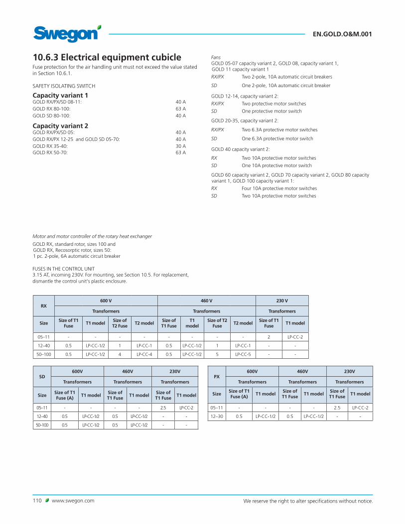
EN.GOLD.O&M.001
110 www.swegon.com We reserve the right to alter specifications without notice.
10.6.3 Electrical equipment cubicleFuse protection for the air handling unit must not exceed the value stated in Section 10.6.1.
SAFETY ISOLATING SWITCH
Capacity variant 1GOLD RX/PX/SD 08-11: 40 AGOLD RX 80-100: 63 AGOLD SD 80-100: 40 A
Capacity variant 2GOLD RX/PX/SD 05: 40 AGOLD RX/PX 12-25 and GOLD SD 05-70: 40 AGOLD RX 35-40: 30 A GOLD RX 50-70: 63 A
FansGOLD 05-07 capacity variant 2, GOLD 08, capacity variant 1, GOLD 11 capacity variant 1
RX/PX Two 2-pole, 10A automatic circuit breakers
SD One 2-pole, 10A automatic circuit breaker
GOLD 12-14, capacity variant 2:
RX/PX Two protective motor switches
SD One protective motor switch
GOLD 20-35, capacity variant 2:
RX/PX Two 6.3A protective motor switches
SD One 6.3A protective motor switch
GOLD 40 capacity variant 2:
RX Two 10A protective motor switches
SD One 10A protective motor switch
GOLD 60 capacity variant 2, GOLD 70 capacity variant 2, GOLD 80 capacity variant 1, GOLD 100 capacity variant 1:
RX Four 10A protective motor switches
SD Two 10A protective motor switches
FUSES IN THE CONTROL UNIT3.15 AT, incoming 230V. For mounting, see Section 10.5. For replacement, dismantle the control unit's plastic enclosure.
Motor and motor controller of the rotary heat exchanger
GOLD RX, standard rotor, sizes 100 and GOLD RX, Recosorptic rotor, sizes 50: 1 pc. 2-pole, 6A automatic circuit breaker
RX600 V 460 V 230 V
Transformers Transformers Transformers
SizeSize of T1
FuseT1 model
Size of T2 Fuse
T2 modelSize of T1 Fuse
T1 model
Size of T2 Fuse
T2 modelSize of T1
FuseT1 model
05–11 - - - - - - - - 2 LP-CC-2
12–40 0.5 LP-CC-1/2 1 LP-CC-1 0.5 LP-CC-1/2 1 LP-CC-1 - -
50–100 0.5 LP-CC-1/2 4 LP-CC-4 0.5 LP-CC-1/2 5 LP-CC-5 - -
SD600V 460V 230V
Transformers Transformers Transformers
SizeSize of T1 Fuse (A)
T1 modelSize of T1 Fuse
T1 modelSize of T1 Fuse
T1 model
05–11 - - - - 2.5 LP-CC-2
12–40 0.5 LP-CC-1/2 0.5 LP-CC-1/2 - -
50–100 0.5 LP-CC-1/2 0.5 LP-CC-1/2 - -
PX600V 460V 230V
Transformers Transformers Transformers
SizeSize of T1 Fuse (A)
T1 modelSize of T1 Fuse
T1 modelSize of T1 Fuse
T1 model
05–11 - - - - 2.5 LP-CC-2
12–30 0.5 LP-CC-1/2 0.5 LP-CC-1/2 - -

www.swegon.com 111We reserve the right to alter specifications without notice.
EN.GOLD.O&M.001
10.6.4 Motor in rotary heat exchanger
10.6.4.1 Standard rotor GOLD RX 05-30: Stepping motor, 2 Nm On starting max. 6.0 A/77 W. During operation max. 5 A/69 W.GOLD RX 35-40: Stepping motor, 4 Nm On starting max. 9.6 A/146 W. During operation max. 8A/130W.GOLD RX 50-80: Stepping motor, 6 Nm On starting max. 12 A/220 W. During operation max. 10A/195W.GOLD RX 100: 3-phase step motor. Max 4.5 A/380 W.
10.6.4.2 Recosorptic rotorGOLD RX 05-08: Stepping motor, 2 Nm On starting: max. 6.0 A/77 W. During operation: max. 5 A/69 W.GOLD RX 11-40: Stepping motor, 4 Nm On starting: max. 9.6A/146W. During operation: max. 8A/130W.GOLD RX 50-100: 3-phase stepping motor. Max 4.5 A/380 W.
10.6.5 Control inaccuracyTemperature ± 1oC.Airflow ± 5%.
10.7 Volume of glycol/water SD coil heat exchangersTotal volume of the coils (excl. pipework package and piping):SD, size 11/12 58 litresSD, size 14/20 90 litresSD, size 25/30 136 litres SD, size 35/40 184 litresSD, size 50/60 256 litresSD, size 70/80 280 litresSD, size 100 452 litres

EN.GOLD.O&M.001
112 www.swegon.com We reserve the right to alter specifications without notice.
All documentation is available in digital form and can be downloaded fromwww.swegon.com