Embed Size (px)
Citation preview
Operating System
(May 2018)
Q.1. a) Explain the difference between monolithic and micro kernel 5M
b) What is Mutual Exclusion? Explain its Significance. 5M
At the same time as one processor executes the shared variable, all remaining processes
wishing to accomplish so at the same instant should be kept waiting; when that process
has over executing the shared variable, one of the processes waiting to perform so should
be permitted to carry on. In this manner, each process executing the shared variable keep
outs all others from doing so at the same time. Only one process should be allowed to
execute in critical section. This is called as Mutual Exclusion.
Monolithic Kernel Micro Kernel
1. If virtually entire operating system code is executed in kernel mode, then it is a monolithic program that runs in a single address space.
1. In microkernel, set of modules for managing the hardware is kept which can uniformly well be executed in user mode. A small microkernel contains only code that must execute in kernel mode. It is the second part of operating system.
2. There is same address space for user mode as well as kernel mode.
2. There is different address space for user mode as well as kernel mode.
3. It has a large space as compared to micro kernel.
3. It has a small space as compared to monolithic kernel.
4. Execution speed is faster than micro kernel.
4. Execution speed is slower than monolithic kernel.
5. If one service crashes whole operating system fails.
5. If one service crashes whole operating system do not fails, it does not affect working of other part micro kernel.
6. Kernel calls the function directly for communication.
6. Communication is done through message passing.
Significance:
1) It avoids Race around condition.
2) Prevents multiple threads to enter critical section at the same time.
c) Discuss various Scheduling Criteria. 5M
A number of scheduling algorithms are being designed that can be applied to different
processes having different properties. The scheduling criteria are mentioned below.
* CPU Utilization – It is amount of time CPU remains busy.
* Throughput – Number of jobs processed per unit time.
* Turnaround Time – Time elapsed between submission of jobs and completion of its
execution.
* Waiting Time – Processes waits in ready queue to get CPU. Sum of times spent In ready
queues waiting time.
* Response Time – Time from submission till the first response is produced.
* Fairness – Every process should get fair share of the CPU time.
d) Explain various file allocation techniques. 5M
Files are usually stored on secondary storage devices such as disk. These files are then
called back when needed. As part of their implementation, files must be stored in the hard
disk. This has to be done in such a way that the disk space is utilized effectively and the
files can be accessed quickly. There are following methods used majority in different
operating system:
Contiguous allocation
Linked List allocation
Linked List allocation using a table in memory.
Indexed allocation
I-nodes
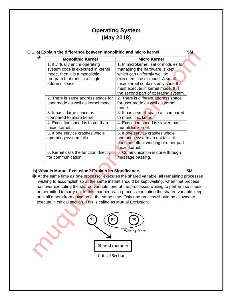
1) Contiguous Allocation: Each file takes up a set of contiguous blocks on the disk. Disk
address defines a linear ordering on the disk. If each block size on disk is 2 KB, then 30
KB file would be allocated 15 consecutive blocks. The directory entry for each file
specifies the address of the starting block and the total number of blocks allocated for
this file. Directory entry is shown below. File A starts at block 0 and it is 3 block long
occupying block 0.

Advantage:
• Contiguous allocation is easy to implement.
Disadvantage:
• When allocated file is deleted, continuously allocated blocks to the file become free.
2) Linked List Allocation: This overcomes the disadvantage of contiguous allocation. In
linked list allocation, each file is linked list of disk block. The scattered disk on the disk
can be allocated to the file. The directory contains a pointer to the first and the last block.
Below figure shows thee linked list allocation for file Pics. The file pics of 5 blocks starts
at block 2 and continue 13, then block 18, then block 12, and finally block 7.
Advantage:
• Reading file sequentially is simple.
Disadvantage:
• In each block pointer takes some space, so each file requires slightly more disk space
rather than its actual size.
3) Linked List allocation using table in memory: Each block needs to store pointer
information; therefore, entire block is not fully used to store file content. This limitation
can be overcome by keeping pointer information in table which always remains in
memory. Refer Linked list fig for Table.
Physical Next block
0 2 (File Pics
Starts from here )
1 13
2 18
3 12
Advantage:
• Random access is much easier
Disadvantage:
• Whole table must be in memory all the time to make it work.
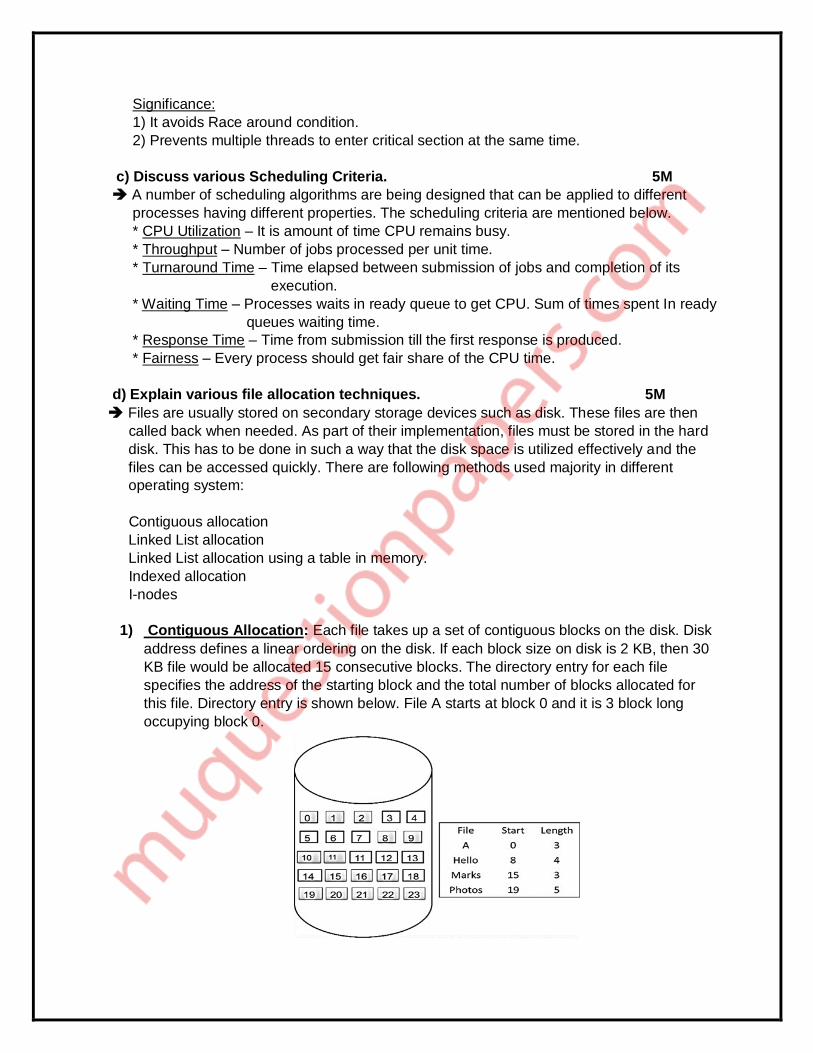
4) Indexed allocation: With file allocation table in memory, Linked list allocation support
random access, but this entire table must be in memory all the time. In indexed
allocation, all the pointers are kept in one location called as index block. There is an
index block assigned to each file and this index block holds the disk block addresses of
that particular file.
Advantage:
• Indexed allocation supports random access.
Disadvantage:
• The pointer overhead of index block is more with compare to the pointer overhead of
linked allocation.
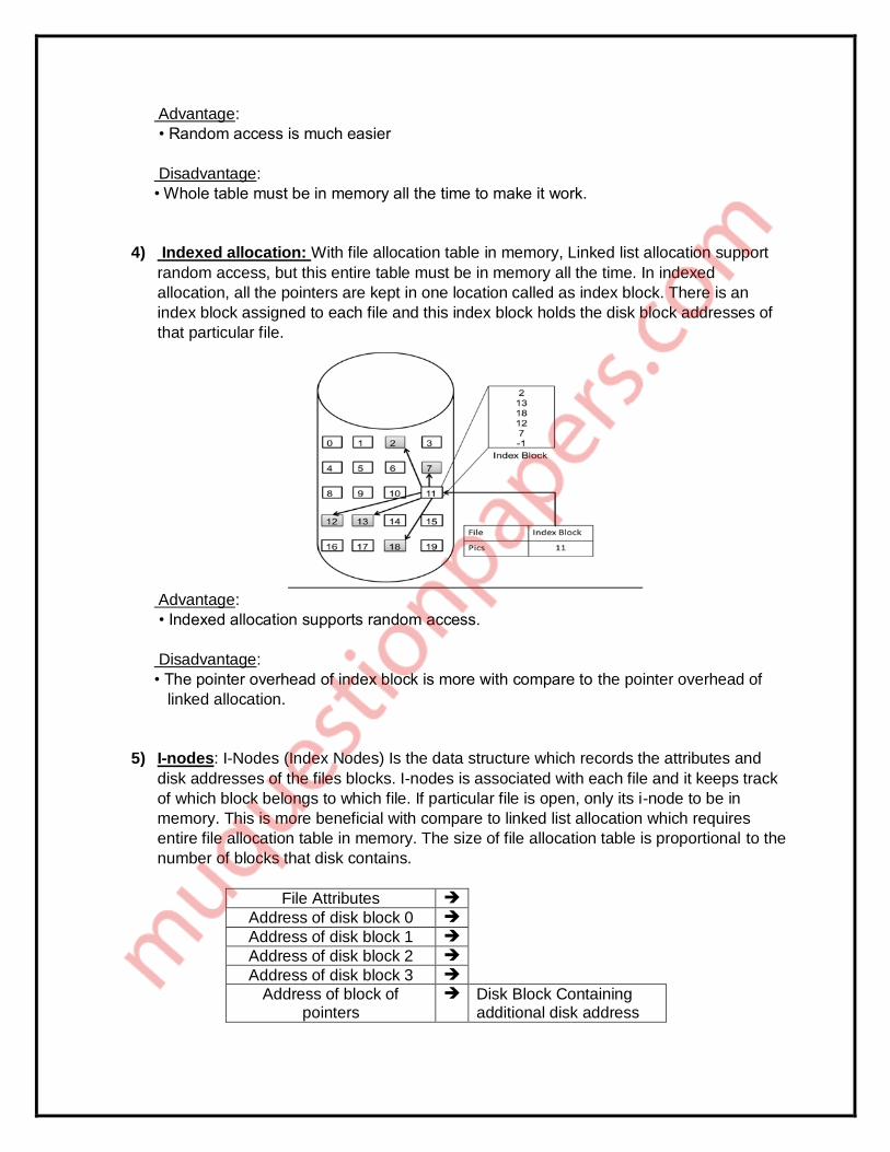
5) I-nodes: I-Nodes (Index Nodes) Is the data structure which records the attributes and
disk addresses of the files blocks. I-nodes is associated with each file and it keeps track
of which block belongs to which file. If particular file is open, only its i-node to be in
memory. This is more beneficial with compare to linked list allocation which requires
entire file allocation table in memory. The size of file allocation table is proportional to the
number of blocks that disk contains.
File Attributes
Address of disk block 0
Address of disk block 1
Address of disk block 2
Address of disk block 3
Address of block of pointers
Disk Block Containing additional disk address
e) Explain the disk cache. 5M
1) In main memory, a buffer is reserved for disk sectors called as cache.
2) The cache keeps copy of data in some of the sectors on the disk.
3) To fulfill an I/O request for a particular sector, first disk cache is checked to see
whether the sector is in disk cache.
4) If it is present, then request is fulfilled via the cache.
5) If not present, then required sector is read into the disk cache from the disk.
6) The disk cache improves the performance as some request is satisfied from it.
7) The property of locality of reference is used.
8) When a block of data is present in cache to fulfill a single I/O request, it is expected
that same block will be needed in future.
____________________________________________________________________________
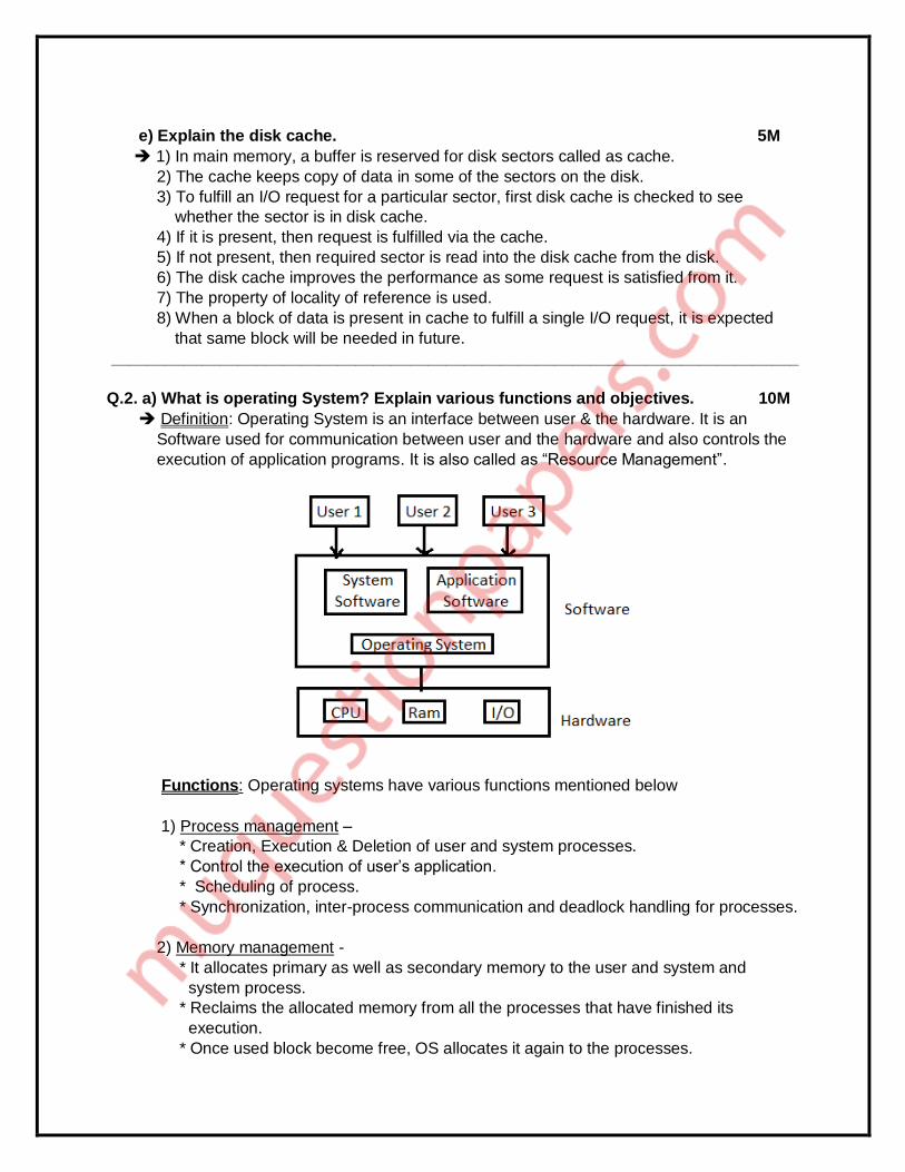
Q.2. a) What is operating System? Explain various functions and objectives. 10M
Definition: Operating System is an interface between user & the hardware. It is an
Software used for communication between user and the hardware and also controls the
execution of application programs. It is also called as “Resource Management”.
Functions: Operating systems have various functions mentioned below
1) Process management –
* Creation, Execution & Deletion of user and system processes.
* Control the execution of user’s application.
* Scheduling of process.
* Synchronization, inter-process communication and deadlock handling for processes.
2) Memory management -
* It allocates primary as well as secondary memory to the user and system and
system process.
* Reclaims the allocated memory from all the processes that have finished its
execution.
* Once used block become free, OS allocates it again to the processes.

* Monitoring and keeping track of how much memory used by the process.
3) File management -
* Creation & Deletion of files and directories.
* It allocates storage space to the files by using different file allocations methods.
* It keeps back-up of files and offers the security for files.
4) Device management -
* Device drivers are open, closed and written by OS.
* Keep an eye on device driver. communicate, control and monitor the device driver.
5) Protection & Security -
* The resources of the system are protected by the OS.
* Keeps back-up of data.
* Lock the system for security purpose by password.
Objectives: There are three objectives of operating system.
* Convenient – Because pf operating system it is very convenient to use computers.
* Efficiency – Because of operating system efficiency of computer increases. We can
work efficiently. We can use resource efficiently.
* Ability to Evolve – If we add more modules in our computers then also our computer
works It does not get damage.
b) What is deadlock? Explain the necessary and sufficient condition for deadlock.
What is the difference between deadlock avoidance and prevention? 10M
Deadlock:
* We know that processes need different resources in order to complete the execution.
* So in a multiprogramming environment, many processes may compete for a multiple
Number of resources.
* In a system, resources are finite. So with finite number of resources, it is not possible to
fulfill the resource request of all processes.
* When a process requests a resource and if the resource is not available at that time. The
process enters a wait state. In multiprogramming environment, it may happen with many
processes.
* There is chance that waiting processes will remain in same state and will never again
change state.
* It is because the resource they have requested are held by other waiting processes.
When such type of situation occurs then it is called as Deadlock.
The necessary and sufficient conditions for deadlock to occur are:
Mutual Exclusion
o A resource at a time can only be used by one process.
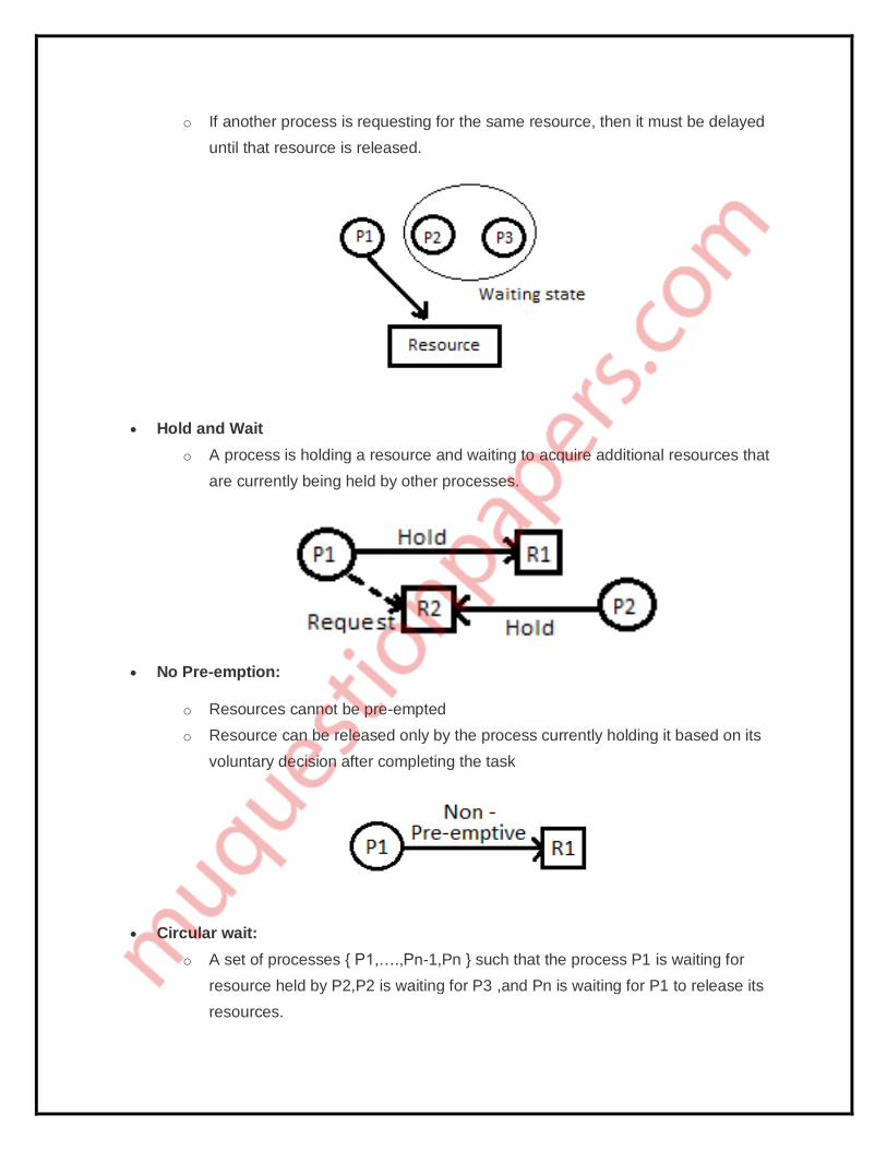
o If another process is requesting for the same resource, then it must be delayed
until that resource is released.
Hold and Wait
o A process is holding a resource and waiting to acquire additional resources that
are currently being held by other processes.
No Pre-emption:
o Resources cannot be pre-empted
o Resource can be released only by the process currently holding it based on its
voluntary decision after completing the task
Circular wait:
o A set of processes { P1,….,Pn-1,Pn } such that the process P1 is waiting for
resource held by P2,P2 is waiting for P3 ,and Pn is waiting for P1 to release its
resources.
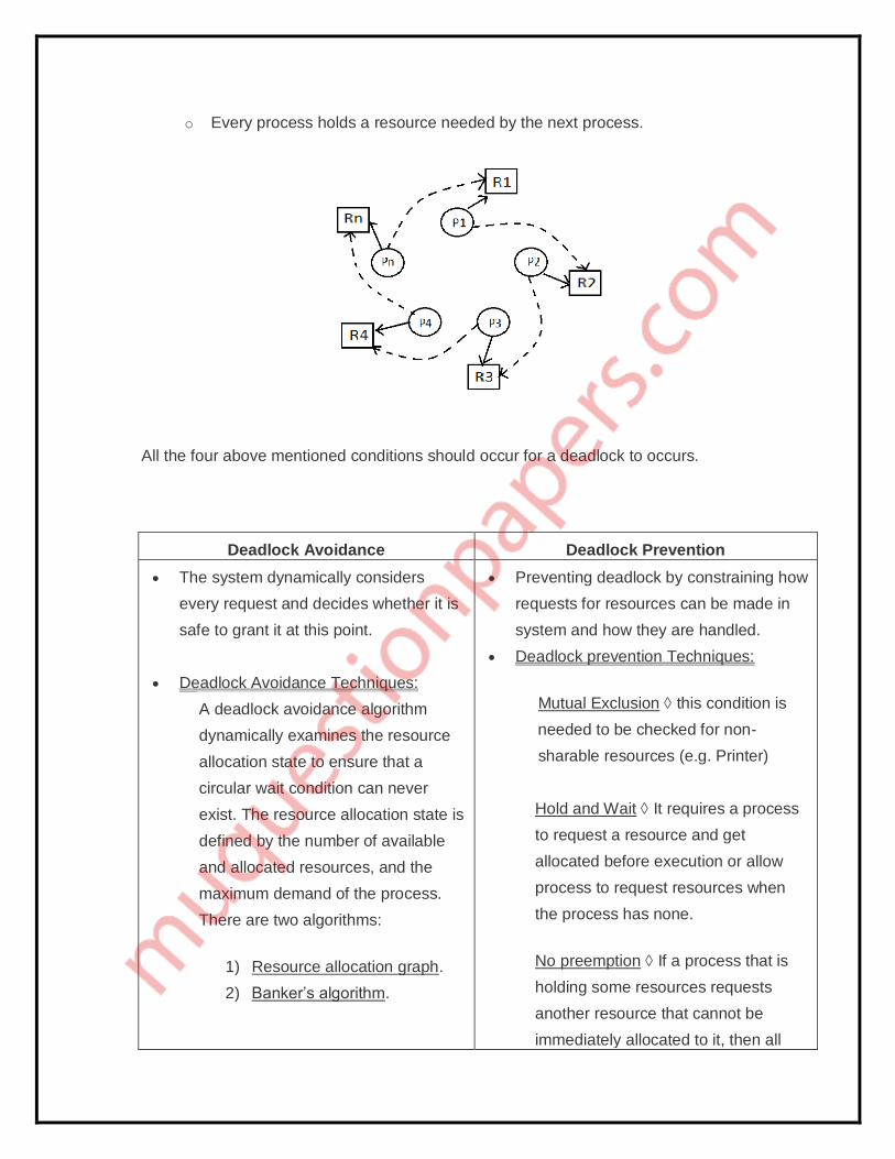
o Every process holds a resource needed by the next process.
All the four above mentioned conditions should occur for a deadlock to occurs.
Deadlock Avoidance Deadlock Prevention
The system dynamically considers
every request and decides whether it is
safe to grant it at this point.
Deadlock Avoidance Techniques:
A deadlock avoidance algorithm
dynamically examines the resource
allocation state to ensure that a
circular wait condition can never
exist. The resource allocation state is
defined by the number of available
and allocated resources, and the
maximum demand of the process.
There are two algorithms:
1) Resource allocation graph.
2) Banker’s algorithm.
Preventing deadlock by constraining how
requests for resources can be made in
system and how they are handled.
Deadlock prevention Techniques:
Mutual Exclusion this condition is
needed to be checked for non-
sharable resources (e.g. Printer)
Hold and Wait It requires a process
to request a resource and get
allocated before execution or allow
process to request resources when
the process has none.
No preemption If a process that is
holding some resources requests
another resource that cannot be
immediately allocated to it, then all

The goal is to ensure that the resource
which are allocated to the process
should be in safe state to avoid
deadlock.
A major drawback of this method is that
it is difficult to know at the beginning
itself of the maximum resource
required.
resources currently being held are
released
Circular Waitwe can impose a total
ordering of all resource types, and ask
that each process requests resources
in an increasing order of enumeration.
The goal is to ensure that at least one of
the above mentioned conditions for
deadlock can never hold.
Disadvantage is that it can lead to low
device utilization and reduced system
throughput.
___________________________________________________________________________
Q.3. a) Explain the following in brief: 10 M
i) Process Synchronization – Process Synchronization means sharing system
resources by processes in such a way that, Concurrent access to shared data is
handled thereby minimizing the chance of inconsistent data.
Each process executes its own operations on shared variables sequentially, as
specified by its own program. Nevertheless, different processes may execute their operations on the same shared variable concurrently. That is, operation executions of different processes may overlap, and they may affect one another.
Each operation on a shared variable, when executed indivisibly, transforms the variable from one consistent value to another. However, when the operations arc executed concurrently on a shared variable, the consistency of its values may not the guaranteed.
The behaviors of operation executions on shared variables must, be predictable for effective inter-process communication.
Thus, operation executions on shared variables may need to be coordinated to ensure their consistency semantics.
Coordination of accesses to shared variables is called synchronization.
A synchronization solution coordinates accesses from processes to shared variables. where all accesses to shared variables are channeled through access controllers
The controllers do the coordination. Most operating systems implement a few different synchronization schemes for process coordination purposes. Each scheme

supports a set of primitives. The primitives are used when it is absolutely necessary to have orderly executions of operations on shared variables in a particular manner.
ii) Inter-Process Communication –
* Synchronization and communication are two basic requirements should be satisfied When processes communicate with each other. * Synchronization of processes is required to achieve the mutual exclusion. * Independent processes do not communicate with each other but cooperating processes may need to exchange information. Cooperative processes either communicates through shared memory or message passing. * Cooperating processes require an inter process communication (IPC) mechanism that will allow them to exchange data and information. * There are two fundamental models of inter process communication. 1) Shared Memory - In the shared memory model, a region of memory that is shared by cooperating processes are established. - Processes can then exchange information by reading and writing data to the shared region. - In the message passing model, communication takes place by means of message exchanged between the cooperating process. 2) Message Passing - Following are the two primitives used in message passing: Send (destination, message) Receive (Source. message) - This is the minimum two operations required for processes to send and receive the message. - A process sends data in the form of a message to another process indicated by destination. - A process receive data by executing the received primitives, indicating the source and the message. b) Consider the following set of processes, assuming all are arriving at time 0. 10M
Calculate average waiting time and turn-around time for FCFS, SJF
(Non-pre-emptive), Priority and RR (Quantum=2).
1) FCFS – Mode- Non-Pre-emptive
Criteria- Arrival Time
Process Burst time Priority
P1 2 2
P2 1 1
P3 8 4
P4 4 5
P5 5 3
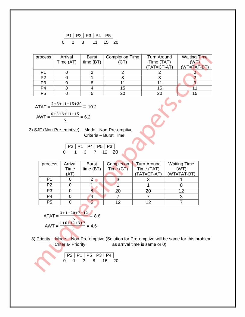
0 2 3 11 15 20
ATAT = 2+3+11+15+20
5 = 10.2
AWT = 0+2+3+11+15
5 = 6.2
2) SJF (Non-Pre-emptive) – Mode - Non-Pre-emptive
Criteria – Burst Time.
P2 P1 P4 P5 P3
0 1 3 7 12 20
process Arrival Time (AT)
Burst time (BT)
Completion Time (CT)
Turn Around Time (TAT)
(TAT=CT-AT)
Waiting Time (WT)
(WT=TAT-BT)
P1 0 2 3 3 1 P2 0 1 1 1 0 P3 0 8 20 20 12 P4 0 4 7 7 3 P5 0 5 12 12 7
ATAT = 3+1+20+7+12
5 = 8.6
AWT = 1+0+12+3+7
5 = 4.6
3) Priority – Mode – Non-Pre-emptive (Solution for Pre-emptive will be same for this problem
Criteria- Priority as arrival time is same or 0)
0 1 3 8 16 20
P1 P2 P3 P4 P5
process Arrival Time (AT)
Burst time (BT)
Completion Time (CT)
Turn Around Time (TAT)
(TAT=CT-AT)
Waiting Time (WT)
(WT=TAT-BT)
P1 0 2 2 2 0
P2 0 1 3 3 2
P3 0 8 11 11 3
P4 0 4 15 15 11
P5 0 5 20 20 15
P2 P1 P5 P3 P4

ATAT = 3+1+16+20+8
5 = 9.6
AWT = 1+0+8+16+3
5 = 5.6
4) RR(Quantum=2) – Mode – Pre-emptive
Criteria – Arrival time
Queue:
P1 P2 P3 P4 P5 P3 P4 P5 P3 P5 P3
0 2 3 5 7 9 11 13 15 17 18 20
process Arrival Time (AT)
Burst time (BT)
Completion Time (CT)
Turn Around Time (TAT)
(TAT=CT-AT)
Waiting Time (WT)
(WT=TAT-BT)
P1 0 2 2 2 0
P2 0 1 3 3 2
P3 0 8 20 20 12
P4 0 4 13 13 9
P5 0 5 18 18 13
ATAT = 2+3+20+13+18
5 = 11.2
AWT = 0+2+12+9+13
5 = 7.2
____________________________________________________________________________
Q.4. a) What is paging? Explain LRU, FIFO and Optimal page replacement policy for the
following String. Page frame size is 4.
1,2,3,4,5,3,4,1,6,7,8,7,8,9,7,8,9,5,4,5,4,2. 10M
Paging:
1. The date required by the application is brought from external memory to the main
memory in form of blocks(pages) This process is called as Paging.
process Arrival Time (AT)
Burst time (BT)
Priority Completion Time (CT)
Turn Around Time (TAT)
(TAT=CT-AT)
Waiting Time (WT)
(WT=TAT-BT)
P1 0 2 2 3 3 1
P2 0 1 1 1 1 0
P3 0 8 4 16 16 8
P4 0 4 5 20 20 16
P5 0 5 3 8 8 3
P1 P2 P3 P4 P5 P3 P4 P5 P3 P5 P3

2. Paging is a memory management scheme which allows the physical address of a
process to be non-contiguous.
3. Paging concept is used to remove the problem fragmentation. Here we are able to
allocate physical memory to the process in non-contiguous manner wherever memory
is available.
4. Paging avoids external fragmentation and need for compaction.
There are three types of page replacement policies explained below:
1) FIFO- In this page replacement policy the page which has arrived first is removed first.
Example:
1 2 3 4 5 3 4 1 6 7 8 7 8 9 7 8 9 5 4 5 4 2
1 1 1 1 5 5 5 5 5 5 8 8 8 8 8 8 8 8 8 8 8 2
2 2 2 2 2 2 1 1 1 1 1 1 9 9 9 9 9 9 9 9 9
3 3 3 3 3 3 6 6 6 6 6 6 6 6 6 5 5 5 5 5
4 4 4 4 4 4 7 7 7 7 7 7 7 7 7 4 4 4 4
M M M M M H H M M M M H H M H H H M M H H M
Page Hit = 9 Page Hit ratio = 9
22 * 100 = 40.90%
Page Miss = 13 Page Miss ratio = 13
22 * 100 = 59.10%
Advantage – Easy to implement
Disadvantage – Performance is not always good. It may suffers from
belady’s anomaly.
2) LRU- In this page replacement policy we replace that page that was used farthest
back in past.
Example:
1 2 3 4 5 3 4 1 6 7 8 7 8 9 7 8 9 5 4 5 4 2
1* 1 1 1 5* 5 5 5 6* 6 6 6 6 6 6 6 6 5* 5 5* 5 5
2* 2 2 2 2 2 1* 1 1 1 1 1 9* 9 9 9* 9 9 9 9 9
3* 3 3 3* 3 3 3 7* 7 7* 7 7 7* 7 7 7 4* 4 4* 4
4* 4 4 4* 4 4 4 8* 8 8* 8 8 8* 8 8 8 8 8 2* M M M M M H H M M M M H H M H H H M M H H M
Page Hit = 9 Page Hit ratio = 9
22 * 100 = 40.90%
Page Miss = 13 Page Miss ratio = 13
22 * 100 = 59.10%
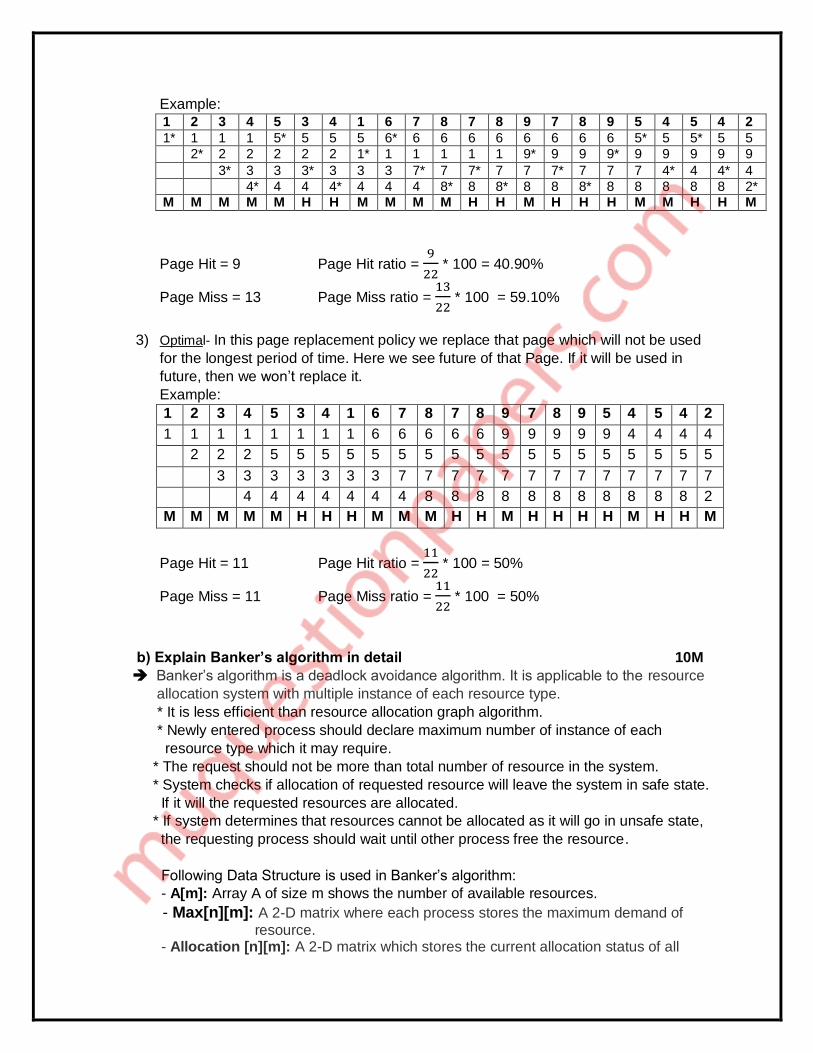
3) Optimal- In this page replacement policy we replace that page which will not be used
for the longest period of time. Here we see future of that Page. If it will be used in
future, then we won’t replace it.
Example:
1 2 3 4 5 3 4 1 6 7 8 7 8 9 7 8 9 5 4 5 4 2
1 1 1 1 1 1 1 1 6 6 6 6 6 9 9 9 9 9 4 4 4 4
2 2 2 5 5 5 5 5 5 5 5 5 5 5 5 5 5 5 5 5 5
3 3 3 3 3 3 3 7 7 7 7 7 7 7 7 7 7 7 7 7
4 4 4 4 4 4 4 8 8 8 8 8 8 8 8 8 8 8 2
M M M M M H H H M M M H H M H H H H M H H M
Page Hit = 11 Page Hit ratio = 11
22 * 100 = 50%
Page Miss = 11 Page Miss ratio = 11
22 * 100 = 50%
b) Explain Banker’s algorithm in detail 10M
Banker’s algorithm is a deadlock avoidance algorithm. It is applicable to the resource
allocation system with multiple instance of each resource type.
* It is less efficient than resource allocation graph algorithm.
* Newly entered process should declare maximum number of instance of each
resource type which it may require.
* The request should not be more than total number of resource in the system.
* System checks if allocation of requested resource will leave the system in safe state.
If it will the requested resources are allocated.
* If system determines that resources cannot be allocated as it will go in unsafe state,
the requesting process should wait until other process free the resource.
Following Data Structure is used in Banker’s algorithm:
- A[m]: Array A of size m shows the number of available resources.
- Max[n][m]: A 2-D matrix where each process stores the maximum demand of
resource. - Allocation [n][m]: A 2-D matrix which stores the current allocation status of all

resource types to various process in the system.
- Need [n][m]: A 2-D matrix which tells the current remaining resource need of each process. It is the maximum demand of a process and the current allocation status. Algorithm: Let process Pi Request i Step1: if Request i ≤ Need Go to step2 else error Step2: if Request i ≤ Available Go to step3 else wait Step3: Available i = Available i – Request i Allocation i = Allocation i + Request i Need i = Need i – Request i Step4: Check if new state is in safe state or not. Safety Algorithm Step1: Work = Available. Finish(i) = false Step2: find an i such that finish[i]=false and need i ≤ work. If no such i, go to step4 Step3: finish[i] = true Work = work + allocation. Go to step2 Step4: If finish[i] = True for all i Then system is safe ___________________________________________________________________________ Q.5. a) What is system call? Explain any five system call in details. 10M
1) The interface between OS and user programs is defined by the set of system calls that the operating system offers. System call is the call for the operating system to perform some task on behalf of the user’s program. Therefore, system calls make up the interface between processes and the operating system. 2) The system calls are functions used in the kernel itself. From programmer’s point view, the system call is a normal C function call.
3) Due to system call, the code is executed in the kernel so that there must be a mechanism to change the process mode from user mode to kernel mode.
System call is categorized in five groups.
Sr. No.
Group Examples
1 Process control End, abort, load, execute, create process, get process attributes, set process attributes, wait for time, wait event, allocate and free memory.
2 Device Manipulation Request device, release device, read, write, reposition, get device attributes, set device attributes, logically attach or detach devices.

3 Communications Create, delete communication connection, send, receive message, transfer status information, attach or detach devices.
4 File Manipulation Create file, delete file, open, close, read, write, reposition, get file attributes, set file attributes.
5 Information Maintenance Get time or date, set time or date, get system data, set system data, get process, file, or device attributes, set process, file or device attributes.
Some examples of System Calls
Open() A program initializes access to a file in a file system using the open system call.
Read() A program that needs to access data from a file stored in a file system uses the read system call.
Write() It writes data from a buffer declared by the user to a given device, maybe a file. This is primary way to output data from a program by directly using a system call.
Exec() exec is a functionality of an operating system that runs an executable file in the context of an already existing process, replacing the previous executable
Fork() fork is an operation whereby a process creates a copy of itself. Fork is the primary method of process creation on Unix-like operating systems.
b) Explain paging hardware with TLB along with protection bits in page table. 10M
The (Translation look aside buffer) TLB is similar to the page table. Important or most used pages are stored in TLB. First pages are searched in TLB if page is found then it proceeds further else it searches pages in page table. TLB reduce execution time. TLB is a piece of very fast, associative memory, capable of searching many areas of memory simultaneously. This means that many table entries can be searched at the same time for a logical-page entry. This type of memory is very expensive which means that not much of it is used; Memory Management Unit (MMUs) usually use TLBs with between 64 and 1024 entries.
A new page table causes all the entries stored in the TLB to become useless. When a new page table is used for example, on a context switch the TLB entries must be erased to make sure the new process's logical-address space maps to the old process's physical-address space.
Protection bits
o With all the paging and replacement that goes on, it might be easy to forget that there needs to be protective barriers thrown up around memory pages.

o We need to prevent code from straying beyond the boundaries of its pages. Our scheme must embrace the swapping and paging ideas we have developed. Protection in a paged environment mug focus on physical-memory frames. Since every memory reference goes through the page table to reference frames, we can add protection bits for frames and store them in the page table. These bits can give certain properties for frames: read-only or read-write.
0 4 Valid
1 Invalid
2 6 Valid
3 Invalid
4 Invalid
5 9 Valid
6 invalid
o For further protection, we can add an execute bit. To support paging, we can add a valid-invalid bit, which indicates if the page being accessed is actually in memory. Note that these protection schemes are focused on the page table. Property bits are the easiest way to provide protection.
o When logical-to-physical translation is taking place, the nature and owner of the request is also analyzed.
If the process that issues the address is not the process that owns the page or if the requested operation is something that is not permitted by the access bits, the attempt is ruled illegal and the operating system is notified. The valid-invalid bit is set when paging occurs. If the bit is set to invalid, this means the page has been swapped to virtual memory and a page fault should be triggered.
____________________________________________________________________________
Q.6. Write short notes on (any two) 20M
a) Linux Virtual file system.
The object oriented principle is used in Virtual File System (VFS). - It has two modules: a set of definitions that states what file –system objects are permissible
to seems to be and software layer for these objects manipulation. - Following four major object types are defined by VFS:
1) I-node Object – An individual file is represented by I-node Object. 2) File Object – An open file is represented by file object. 3) Superblock Object – An entire file system is represented by a Superblock Object. 4) Dentry Object – An individual directory entry is represented by Dentry object.
- A set of operations are defined for each of the type of objects. Each object of one of these points to a function table.
- The record of addresses of the actual functions is kept in function table. These functions implement the defined set of operations for that object.

- The VFS software layer need not recognize earlier about what kind of object it is dealing with. It can carry out an operation on one of the file-system objects by invoking the right function from the object’s function table.
- The VFS remains unaware about whether an i-node represents a networked file, a disk file, a network socket, or a directory file. The function table contains suitable function to read the file.
- The VFS software layer will invoke that function without worrying about the way of reading the data. The file can be accesses with the help of i-node and file objects.
- An i-node object is a data structure that holds pointers to the disk blocks. The actual file data is present on disk block.
- The file object denotes a point of access to the data in an open file. In order to access the i-node contents, the process first has to access a file object pointing to the i-node.
- The i-node objects do not belong to single process. Whereas file objects belong to single process.
- The i-node object is cached by the VFS to get better performance in near future access of the file. Therefore, although processes is not currently using the file, its i-node is cached by VFS.
- All cached file data are linked onto list in the file’s i-node object. The i-node also keeps standard information about each file, for example the owner, size, and time most recently modified.
- Directory files are treated in a different way from other files. - The programming interface of UNIX defines several operations on directories, for example
creation, deletion, and renaming of a file in a directory. - The system calls for these directory operations do not have need of the user open the files
concerned, unlike the case for reading or writing data. - Therefore, these directory operations are defined by VFS in the i-node object, instead of in
the file object. - The super block object represents files of entire file system. - The operating system kernel keeps a single superblock object for each disk device mounted
as a file system and each networked file system at present connected. The main duty of the superblock object is to offer access to i-nodes.
- The VFS recognize each i-node by a unique file-system / i-node number pair. - It locates the i-node analogous to a particular i-node number by requesting the superblock
object to return the i-node with that number. - A entry object represents a directory entry that may include the name of a directory in the
path name of a file (such as /usr) or the actual file. b) Process Control Block
Process Control Block (PCB) is the data structure used by the operating system to keep track on the processes. Any process is identified by its PCB. - All the information associated with process is kept in PCB. There is separate PCB for each process. - Traffic controller module keeps a track on the status of the processes. PCB’s of the processes which are in the same state (ready, waiting, executing, etc) are linked together giving a specific name to the list such as ready list. - If may processes wait for the device, the PCB’s of all these processes are linked together in chain waiting for that device. - If the processes are available in that device chain, then again it is placed back to ready state to request that device again.
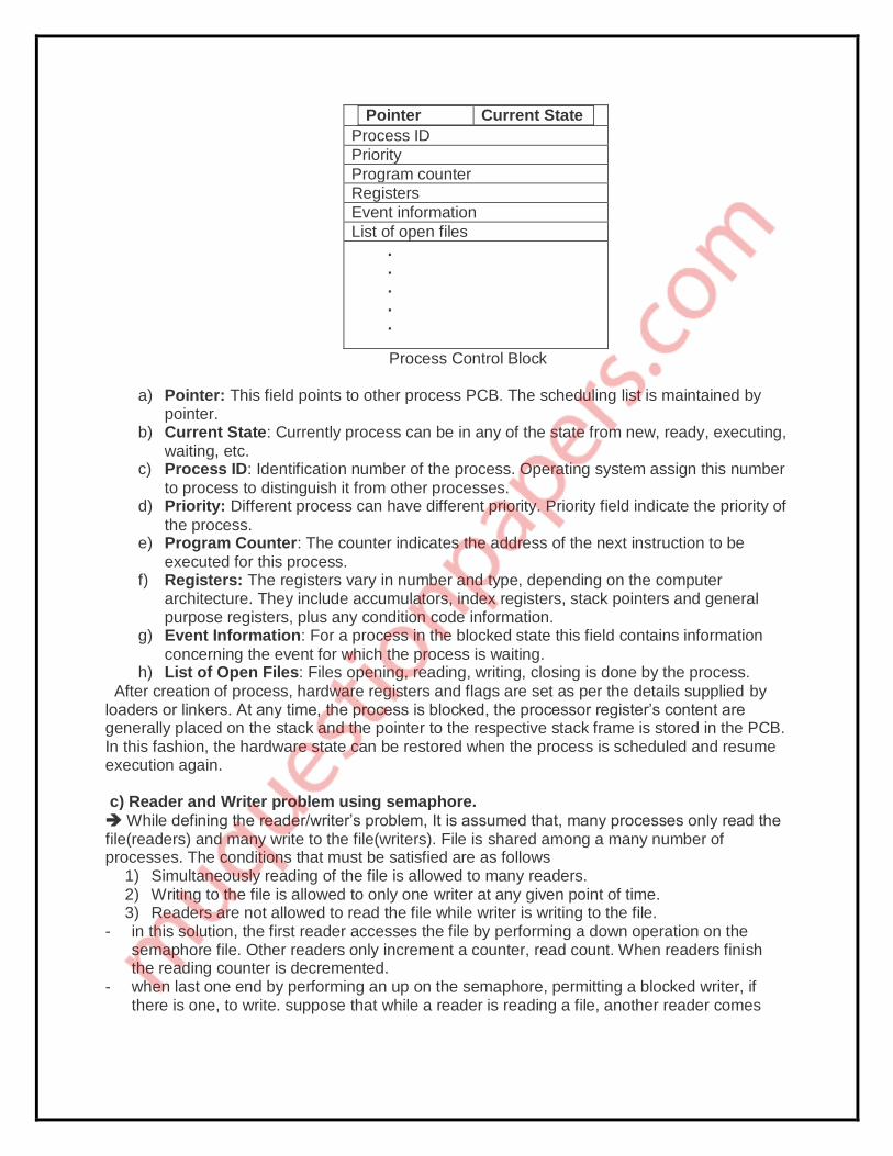
Pointer Current State
Process ID
Priority
Program counter
Registers
Event information
List of open files
. . . . .
Process Control Block
a) Pointer: This field points to other process PCB. The scheduling list is maintained by pointer.
b) Current State: Currently process can be in any of the state from new, ready, executing,
waiting, etc. c) Process ID: Identification number of the process. Operating system assign this number
to process to distinguish it from other processes. d) Priority: Different process can have different priority. Priority field indicate the priority of
the process. e) Program Counter: The counter indicates the address of the next instruction to be
executed for this process. f) Registers: The registers vary in number and type, depending on the computer
architecture. They include accumulators, index registers, stack pointers and general purpose registers, plus any condition code information.
g) Event Information: For a process in the blocked state this field contains information
concerning the event for which the process is waiting. h) List of Open Files: Files opening, reading, writing, closing is done by the process.
After creation of process, hardware registers and flags are set as per the details supplied by loaders or linkers. At any time, the process is blocked, the processor register’s content are generally placed on the stack and the pointer to the respective stack frame is stored in the PCB. In this fashion, the hardware state can be restored when the process is scheduled and resume execution again. c) Reader and Writer problem using semaphore.
While defining the reader/writer’s problem, It is assumed that, many processes only read the file(readers) and many write to the file(writers). File is shared among a many number of processes. The conditions that must be satisfied are as follows
1) Simultaneously reading of the file is allowed to many readers. 2) Writing to the file is allowed to only one writer at any given point of time. 3) Readers are not allowed to read the file while writer is writing to the file.
- in this solution, the first reader accesses the file by performing a down operation on the semaphore file. Other readers only increment a counter, read count. When readers finish the reading counter is decremented.
- when last one end by performing an up on the semaphore, permitting a blocked writer, if there is one, to write. suppose that while a reader is reading a file, another reader comes

along. Since having two readers at the same time is not a trouble, the second readers and later readers can also be allowed if they come.
- After this assumes that a writer wants to perform a write operation on the file. The writer can’t be allowed to write the file, since writer is suspended. The writer will suspend until no reader is reading the file. If new reader arrives continuously with short interval and perform reading, the writer will never obtain the access to the file.
- To stop this circumstance, the program is written in a different way: when a reader comes and at the same time a writer is waiting, the reader is suspended instead of being allowed immediately.
- Now writer will wait for readers that were reading and about to finish but does not have to wait for readers that came along with him. The drawback of this solution is that it achieves less concurrency and thus lower performance. Algorithm
Writer process While(TRUE) { Wait(w) # perform write operation Signal(w) }
Reader Process While(TRUE) { Wait(m) Read_count ++; //reader enters If (Read_count == 1) Wait(w) //blocks writer Signal(m) # perform read operation Wait(m) Read_count - -; If (Read_count == 0) //No reader Signal(w) //Writer can write Signal(m) } d) Explain disk scheduling algorithms. In operating systems, seek time is very important. Since all device requests are linked in
queues, the seek time is increased causing the system to slow down. Disk Scheduling Algorithms are used to reduce the total seek time of any request.
TYPES OF DISK SCHEDULING ALGORITHMS
1) First Come-First Serve (FCFS)
2) Shortest Seek Time First (SSTF)
3) Elevator (SCAN)
4) Circular SCAN (C-SCAN)
5) LOOK
6) C-LOOK
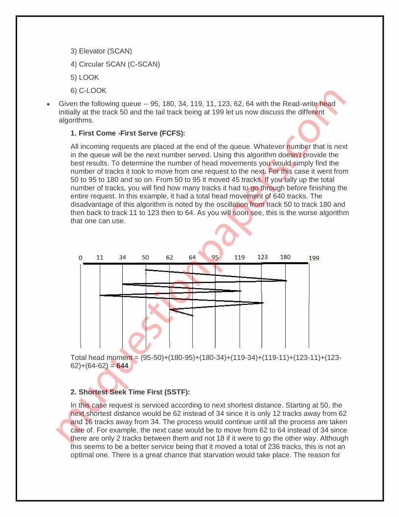
Given the following queue -- 95, 180, 34, 119, 11, 123, 62, 64 with the Read-write head initially at the track 50 and the tail track being at 199 let us now discuss the different algorithms.
1. First Come -First Serve (FCFS):
All incoming requests are placed at the end of the queue. Whatever number that is next in the queue will be the next number served. Using this algorithm doesn't provide the best results. To determine the number of head movements you would simply find the number of tracks it took to move from one request to the next. For this case it went from 50 to 95 to 180 and so on. From 50 to 95 it moved 45 tracks. If you tally up the total number of tracks, you will find how many tracks it had to go through before finishing the entire request. In this example, it had a total head movement of 640 tracks. The disadvantage of this algorithm is noted by the oscillation from track 50 to track 180 and then back to track 11 to 123 then to 64. As you will soon see, this is the worse algorithm that one can use.
Total head moment = (95-50)+(180-95)+(180-34)+(119-34)+(119-11)+(123-11)+(123-62)+(64-62) = 644
2. Shortest Seek Time First (SSTF):
In this case request is serviced according to next shortest distance. Starting at 50, the next shortest distance would be 62 instead of 34 since it is only 12 tracks away from 62 and 16 tracks away from 34. The process would continue until all the process are taken care of. For example, the next case would be to move from 62 to 64 instead of 34 since there are only 2 tracks between them and not 18 if it were to go the other way. Although this seems to be a better service being that it moved a total of 236 tracks, this is not an optimal one. There is a great chance that starvation would take place. The reason for

this is if there were a lot of requests close to each other the other requests will never be handled since the distance will always be greater.
Total head moment = (62-50)+(64-62)+(64-34)+(34-11)+(95-64)+(119-95)+(123-119)+(180-123) = 238
3. Elevator (SCAN):
This approach works like an elevator does. It scans down towards the nearest end and then when it hits the bottom it scans up servicing the requests that it didn't get going down. If a request comes in after it has been scanned it will not be serviced until the process comes back down or moves back up. This process moved a total of 230 tracks. Once again this is more optimal than the previous algorithm, but it is not the best.
Total head moment = (50-34)+(34-11)+(11-0)+(62-0)+(64-62)+(95-64)+(119-95)+(123-119)+(180-123) = 230
4. Circular Scan (C-SCAN)
Circular scanning works just like the elevator to some extent. It begins its scan toward the nearest end and works it way all the way to the end of the system. Once it hits the bottom or top it jumps to the other end and moves in the same direction. Keep in mind that the huge jump doesn't count as a head movement. The total head movement for this algorithm is only 187 tracks, but still this isn't the more sufficient.
Total head moment = (50-34)+(34-11)+(11-0)+(199-0)+(199-180)+(180-123)+(123-119)+(119-95)+(95-64)+(64-62) = 386
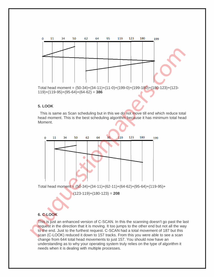
5. LOOK
This is same as Scan scheduling but in this we do not move till end which reduce total head moment. This is the best scheduling algorithm because it has minimum total head Moment.
Total head moment = (50-34)+(34-11)+(62-11)+(64-62)+(95-64)+(119-95)+
(123-119)+(180-123) = 208
6. C-LOOK
This is just an enhanced version of C-SCAN. In this the scanning doesn't go past the last request in the direction that it is moving. It too jumps to the other end but not all the way to the end. Just to the furthest request. C-SCAN had a total movement of 187 but this scan (C-LOOK) reduced it down to 157 tracks. From this you were able to see a scan change from 644 total head movements to just 157. You should now have an understanding as to why your operating system truly relies on the type of algorithm it needs when it is dealing with multiple processes.

Total head moment = (50-34)+(34-11)+(180-11)+(180-123)+(123-119)+(119-95)+ (95-64)+(64-62) = 326
***********