Embed Size (px)
Citation preview

1997 DESIGN 140T GOTTWALD/JAMALPUR CRANE ISSUE 1997
Railway Crane Operating Manual
Rigging 5.1 (P-1/1)
5.1.1 Couple/ Uncouple Match Truck 5.1.2 Suspension Blocking Cylinder/Engage/Disengage Travel Gear 5.1.3 Transport Position 5.1.4 Lower /Raise Counterweight Support/lock/Unlock Superstructure 5.1.5 Brake System 5.1.6 Outriggers 5.1.7 Re-railing 5.1.8 Counterweight 5.1.9 Pick up and Set Down Counterweight 5.1.10 Increase/Decrease Counterweight Radius 5.1.11 Raise /Lower Boom 5.1.12 Retract Main Hoist Hook Block to Boom

1997 DESIGN 140T GOTTWALD/JAMALPUR CRANE ISSUE 1997
Railway Crane Operating Manual
Couple/Uncouple the Match Truck 5.1.1 (P-1/1)
Description
The match truck serves in the train formation to store and to protect the boom as the boom protrudes beyond the buffer. The match truck is not part of the scope of supply. Should a match truck without a handbrake arrangement be used, the match truck must be underpinned with drag shoes when it is parked.
Safety Instructions
Use caution in the area between the crane and the match truck. Standing between crane and match truck is prohibited during pulling in and out! Danger of being crushed! Danger of accidents! Operating Instructions The following procedures are applicable for coupling the match truck to and uncoupling the match truck from the crane as well as coupling the crane or match truck to and uncoupling the crane or match truck from other wagons in the train formation. 1. To couple:
Travel the crane to the match truck buffer. Note: Please maintain the following work sequence: • Connect the hook • Secure the crane and the match truck against rolling according to regulations • Connect the brake air pressure or vacuum brake system coupling heads • Air pressure brake system only: Open the stops for the brake air pressure • If necessary, remove drag shoes • Release the handbrake (See section 5.1.5 on the Brake System)
2. To Uncouple:
It is assumed that the match truck remains at the uncoupling site and the crane travels to job site. Note: Please maintain the following work sequence: • Secure the crane against rolling according to regulations • Apply the match truck handbrake and, if necessary, underpin with drag shoes • Air pressure brake system only: Close the stops cocks for the brake air pressure • Release the brake air pressure or vacuum brake system coupling heads • Disconnect the train hook

1997 DESIGN 140T GOTTWALD/JAMALPUR CRANE ISSUE 1997
Railway Crane Operating Manual
Suspension Blocking Cylinder/Engage/Disengage Traveling Gear 5.1.2 (P-1/1)
Description
The spring deflection on the wheel set springs is blocked via hydraulic cylinders during crane and travel operations. When the crane is being hauled in train formation, the suspension spring block is released. The travel gear must be disengaged when the crane is being hauled in train formation. The change-over for “engage/disengage travel gear” is coupled to the suspension spring blocking as the suspension spring blocking is released for hauling in train formation.
Safety Instructions
Caution – Change-over may be only be carried out when the crane is at a standstill! Secure the crane according to regulations against rolling. Caution! - The condition of the suspension blocking cylinders must be checked after change-over, i.e. it must be checked as to whether the suspension blocking cylinders have been engaged or disengaged.
Operating Instructions The change- over for the suspension blocking cylinders is located on the undercarriage. It is coupled to the function engage/disengage travel gear”. 1. Crane and travel operations:
To engage travel gear / switch on suspension blocking: • Suspension blocking “ON” – Place lever (Item 1) in upright position. • The indicator (Item 2) is red.
2. Hauling operation in train formation: To disengage travel gear /switch off suspension blocking: • Suspension blocking “OFF” Place lever (Item 1) in downward position. • The indicator (item 2) is green.

1997 DESIGN 140T GOTTWALD/JAMALPUR CRANE ISSUE 1997
Railway Crane Operating Manual
Transport Position 5.1.3 (P-1/2)
Description Transport position is to be understood as the position specified for the crane when it is being hauled in train formation.
Safety Instructions
Conveying persons or loads in the customary fashion is prohibited!
Operating Instructions Transport position: The crane wagon may only be traveled when:
1. the crane wagon is coupled to the match truck.
1. a the counterweights are stored on the match truck and the remaining counterweight on the undercarriage is place on the cab side and secured
2. the crane superstructure is locked to the undercarriage by means of the lowered counterweight support
3. the boom is stored on and locked to the match truck
3. a the ropes are slack
4. the hook gear is stored properly on the match truck.
1997 DESIGN 140T GOTTWALD/JAMALPUR CRANE ISSUE 1997
Railway Crane Operating Manual
Transport Position 5.1.3 (P-2/2)
5. The travel gear pinions are disengaged and suspension blocking is switched on
6. The outrigger pads are stored in their mountings on the match truck
7. The outrigger cylinders have been retracted to their retainers and the outrigger beams have been swung in and secured
8. The parking brake has been released
8. a The barking system is set to the corresponding brake system (vacuum/air pressure).
Conveyance in both travel directions is permissible.
1997 DESIGN 140T GOTTWALD/JAMALPUR CRANE ISSUE 1997
Railway Crane Operating Manual Lower/Raise the Counterweight Support/ Lock/Unlock Superstructure 5.1.4
(P-1/2)
Description
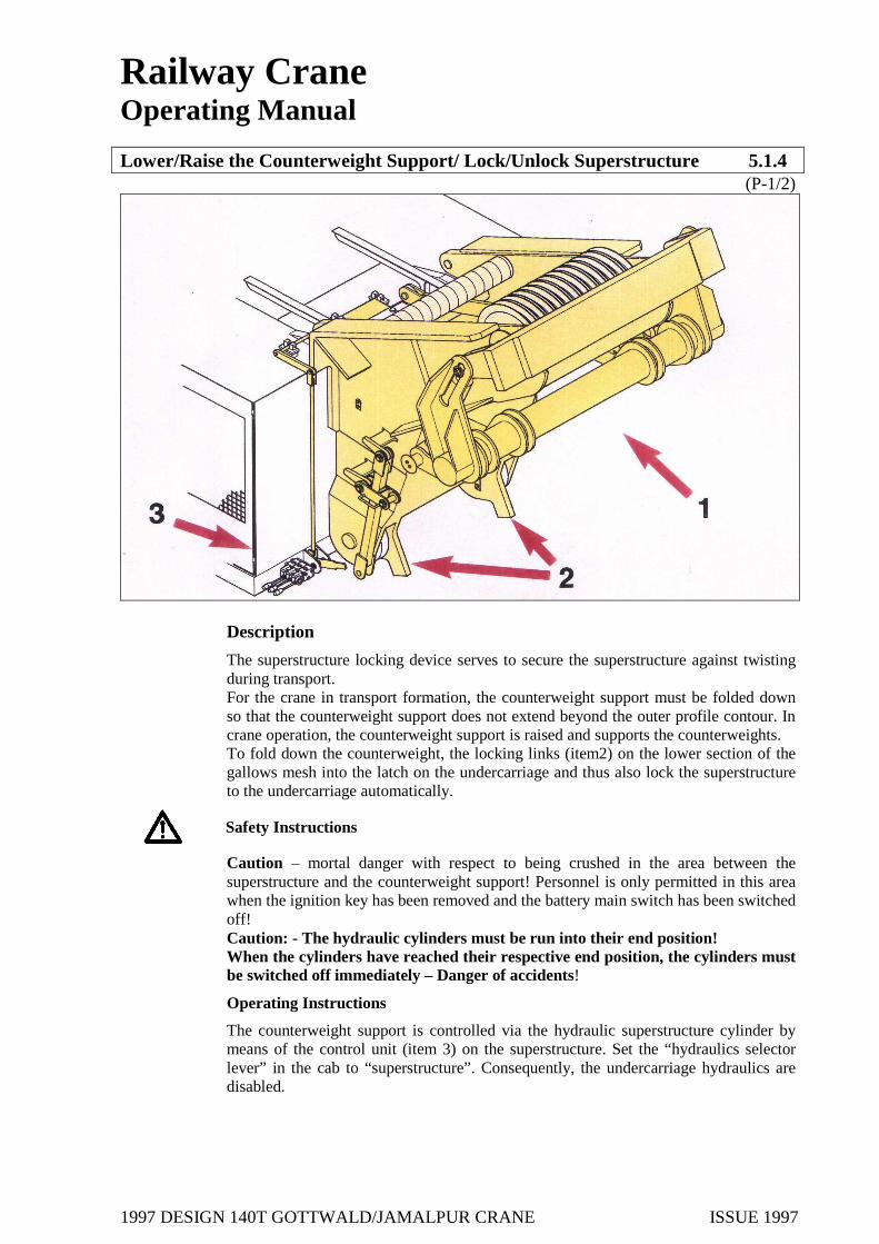
The superstructure locking device serves to secure the superstructure against twisting during transport. For the crane in transport formation, the counterweight support must be folded down so that the counterweight support does not extend beyond the outer profile contour. In crane operation, the counterweight support is raised and supports the counterweights. To fold down the counterweight, the locking links (item2) on the lower section of the gallows mesh into the latch on the undercarriage and thus also lock the superstructure to the undercarriage automatically.
Safety Instructions
Caution – mortal danger with respect to being crushed in the area between the superstructure and the counterweight support! Personnel is only permitted in this area when the ignition key has been removed and the battery main switch has been switched off! Caution: - The hydraulic cylinders must be run into their end position! When the cylinders have reached their respective end position, the cylinders must be switched off immediately – Danger of accidents!
Operating Instructions
The counterweight support is controlled via the hydraulic superstructure cylinder by means of the control unit (item 3) on the superstructure. Set the “hydraulics selector lever” in the cab to “superstructure”. Consequently, the undercarriage hydraulics are disabled.
1997 DESIGN 140T GOTTWALD/JAMALPUR CRANE ISSUE 1997
Railway Crane Operating Manual Lower/Raise the Counterweight Support/ Lock/Unlock Superstructure 5.1.4
(P-2/2)
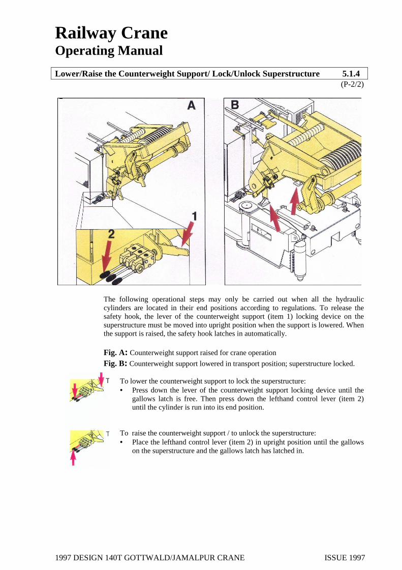
The following operational steps may only be carried out when all the hydraulic cylinders are located in their end positions according to regulations. To release the safety hook, the lever of the counterweight support (item 1) locking device on the superstructure must be moved into upright position when the support is lowered. When the support is raised, the safety hook latches in automatically.
Fig. A: Counterweight support raised for crane operation
Fig. B: Counterweight support lowered in transport position; superstructure locked. To lower the counterweight support to lock the superstructure: • Press down the lever of the counterweight support locking device until the
gallows latch is free. Then press down the lefthand control lever (item 2) until the cylinder is run into its end position.
To raise the counterweight support / to unlock the superstructure: • Place the lefthand control lever (item 2) in upright position until the gallows
on the superstructure and the gallows latch has latched in.

1997 DESIGN 140T GOTTWALD/JAMALPUR CRANE ISSUE 1997
Railway Crane Operating Manual
Brake System 5.1.5 (P-1/4)
Description
The crane is fitted with a dual brake system. The crane can be operated with the air pressure brake system or the vacuum brake system. Switch-over is carried out by means of two levers, which are located on both sides of the cranes. In addition, the crane has a parking brake with a quick-release device which can be controlled independently of the train brake system by means or air pressure or the vacuum system. The status of the brakes can be read off via the corresponding indicators (red and green). The spring–loaded cylinders also have a mechanical emergency release device which can be actuated by means of Bowden cables on the axles. Caution! – If the emergency release device is used, you must pressurize the brake system with air pressure before you can be begin a new braking procedure.
Safety Instructions
Caution! – Please note that the brake system must be pressurized before a new braking procedure can be carried out when the Bowden cables have been activated. Prior to releasing the parking brake, start up the crane and secure via the service brake. On exiting the crane, always apply (switch on) the parking brake. Caution! – Only begin travel operation when the parking brake has been completely released! - It is prohibited to begin travel when the brake is still on.
Operating Instructions
1. To apply parking brake: � Place the parking brake lever (Item 1) to “On” position. The “parking brake”
indicator (Item 2) is red.

1997 DESIGN 140T GOTTWALD/JAMALPUR CRANE ISSUE 1997
Railway Crane Operating Manual
Brake System 5.1.5 (P-2/4)
To release parking brake: • Place the parking brake lever (Item 1) to the “Off” position. The “braking
brake” indicator (Item 2) is green. 2. To release the brake quickly:
The brake has handle (Item 3) for quick-release. The quick-release acts directly on the KE brake valve during operation of the air pressure system or on the vacuum control valve during vacuum operation: To operate the quick-release for the air pressure system: • Pull out the handle once until the brake has been completely released (opened). To operate the quick-release for the vacuum system: • Pull out the handle once until the vacuum has been completely equalized.
3. To switch the brake system from air pressure to vacuum:
Note: The switch-over devices for the air pressure and vacuum systems are coupled to each other mechanically, i.e. when the air pressure brake system is switched on, the vacuum brake system is switched off automatically and vice versa. Generally, the following applies: Lever in horizontal position: Brake “ON”, Lever in vertical position Brake “OFF”. It is also possible to switch off both brake systems simultaneously. Caution: danger of the crane rolling – secure the crane without fail using drag shoes.

1997 DESIGN 140T GOTTWALD/JAMALPUR CRANE ISSUE 1997
Railway Crane Operating Manual
Brake System 5.1.5 (P-3/4)
1. To switch on the air pressure brake: • Set the air pressure brake (Item 4) to “On”. The “service brake” indicator (item
6) is red. 2. To switch off air pressure brake: • Set the air pressure brake (Item 4) to “Off”. The “service brake” indicator (Item
6) is red. 3. To switch on the vacuum brake: • Set the vacuum brake (item 5) to “On”. The “service brake” indicator (Item 6) is
red. 4. To switch off the vacuum brake: • Set the vacuum brake (Item 5) to “Off”. The “service brake” indicator (Item 6) is
red. 5 To switch off the service brake: Both brake system can be switched off: • Set the levers (Item 4 and 5) to “Off”. The “service brake” indicator (Item 6) is
green.

1997 DESIGN 140T GOTTWALD/JAMALPUR CRANE ISSUE 1997
Railway Crane Operating Manual
Brake System 5.1.5 (P-4/4)
6. Mechanical emergency release device of the spring-loaded cylinders (not illustrated): Caution! – Once the Bowden cables have been actuated, the crane is without brakes until the brake have been re-pressurized Danger of accidents! The mechanical emergency quick-release device is actuated via 6 Bowden cables on the bogies. The spring-loaded brake is not active until sufficient pressure is available. The pressure required can be generated via the compressor on the diesel engine or the air pressure compressors in the undercarriage. When the pressure required is to be generator during travel in an air pressure operated train, set the control lever for the parking brake on the undercarriage to “released” position. Otherwise the parking brake closes automatically when the activating pressure has been reached. When the pressure is set in a vacuum brake operated train, the air supply for activating the spring-loaded and service brakes must be checked prior to departure, as no braking function is possible until the pressure has been generated via the axle compressors. Filling only the main air line is not sufficient to activate the brake system (max. 5bar) but it is enough to make the service brake functional. Parking the crane rake is released is prohibited. Danger of the crane rolling! Secure the crane by means of drag shoes or the like. To actuate the emergency quick-release device: • Pull the Bowden cables on the bogies to release the spring –loaded
cylinders.
1997 DESIGN 140T GOTTWALD/JAMALPUR CRANE ISSUE 1997
Railway Crane Operating Manual
Outriggers 5.1.6 (P-1/3)
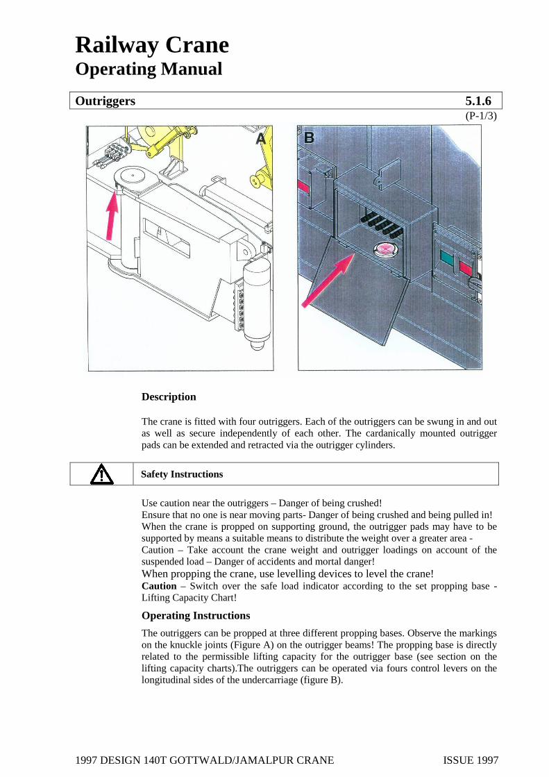
Description The crane is fitted with four outriggers. Each of the outriggers can be swung in and out as well as secure independently of each other. The cardanically mounted outrigger pads can be extended and retracted via the outrigger cylinders.
Safety Instructions
Use caution near the outriggers – Danger of being crushed! Ensure that no one is near moving parts- Danger of being crushed and being pulled in!
When the crane is propped on supporting ground, the outrigger pads may have to be supported by means a suitable means to distribute the weight over a greater area - Caution – Take account the crane weight and outrigger loadings on account of the suspended load – Danger of accidents and mortal danger! When propping the crane, use levelling devices to level the crane! Caution – Switch over the safe load indicator according to the set propping base - Lifting Capacity Chart!
Operating Instructions
The outriggers can be propped at three different propping bases. Observe the markings on the knuckle joints (Figure A) on the outrigger beams! The propping base is directly related to the permissible lifting capacity for the outrigger base (see section on the lifting capacity charts).The outriggers can be operated via fours control levers on the longitudinal sides of the undercarriage (figure B).
1997 DESIGN 140T GOTTWALD/JAMALPUR CRANE ISSUE 1997
Railway Crane Operating Manual
Outriggers 5.1.6 (P-2/3)
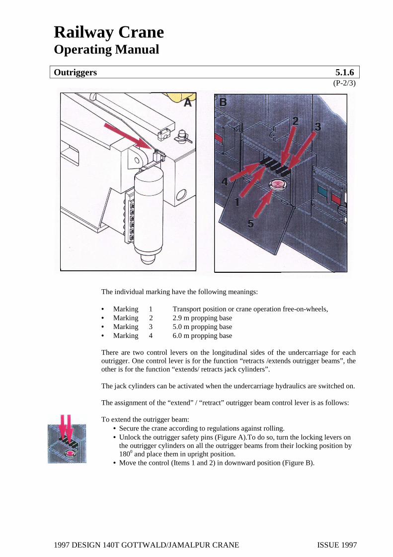
The individual marking have the following meanings: • Marking 1 Transport position or crane operation free-on-wheels, • Marking 2 2.9 m propping base • Marking 3 5.0 m propping base • Marking 4 6.0 m propping base There are two control levers on the longitudinal sides of the undercarriage for each outrigger. One control lever is for the function “retracts /extends outrigger beams”, the other is for the function “extends/ retracts jack cylinders”. The jack cylinders can be activated when the undercarriage hydraulics are switched on. The assignment of the “extend” / “retract” outrigger beam control lever is as follows: To extend the outrigger beam:
• Secure the crane according to regulations against rolling. • Unlock the outrigger safety pins (Figure A).To do so, turn the locking levers on
the outrigger cylinders on all the outrigger beams from their locking position by 1800 and place them in upright position.
• Move the control (Items 1 and 2) in downward position (Figure B).
1997 DESIGN 140T GOTTWALD/JAMALPUR CRANE ISSUE 1997
Railway Crane Operating Manual
Outriggers 5.1.6 (P-3/3)
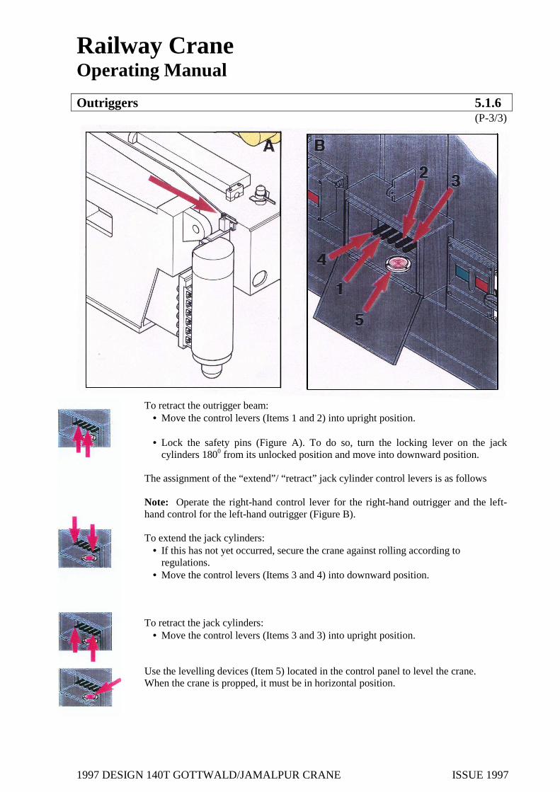
To retract the outrigger beam:
• Move the control levers (Items 1 and 2) into upright position.
• Lock the safety pins (Figure A). To do so, turn the locking lever on the jack cylinders 1800 from its unlocked position and move into downward position.
The assignment of the “extend”/ “retract” jack cylinder control levers is as follows Note: Operate the right-hand control lever for the right-hand outrigger and the left-hand control for the left-hand outrigger (Figure B). To extend the jack cylinders:
• If this has not yet occurred, secure the crane against rolling according to regulations.
• Move the control levers (Items 3 and 4) into downward position. To retract the jack cylinders:
• Move the control levers (Items 3 and 3) into upright position.
Use the levelling devices (Item 5) located in the control panel to level the crane. When the crane is propped, it must be in horizontal position.

1997 DESIGN 140T GOTTWALD/JAMALPUR CRANE ISSUE 1997
Railway Crane Operating Manual
Re-Railing 5.1.7 (P-1/1)
Description
In the event that the crane is de-railed, the crane can be re-railed by using the hydraulic outriggers.
Safety Instructions
Use caution near the outriggers- Danger of being crushed!
Ensure that no one is near moving parts- Danger of being crushed and being pulled in! When the crane is propped on supporting ground, the outrigger pads may have to be; supported by means a suitable means to distribute the weight over a greater area- Caution – Remember to take the load attached when cane weight and outrigger loadings are calculated- Danger of accidents! Mortal danger! Caution – an increase degree of attention is required for re-railing –Danger of accidents! Mortal danger!
Operating Instructions
The individual bogies are re-railed, i.e. first the front and then the rear bogie. Let us assume that the crane has de-railed to the left of the track. The diesel engine is running and the outrigger beams are unlocked. 1. Set the “hydraulics” selector switch to “undercarriage” 2. Extend the outrigger beams, as described, to the middle propping base beams
3. Position the outrigger pads, extend the right and left outrigger and raise the crane
evenly in this way.
4. Simultaneously retract the right-hand outrigger beam and extend the left-hand outrigger beam until the wheels of the bogie are located directly above the rails or have reached the maximum width of 50 mm. If the cylinders must be run shift the crane again, the right and left jack cylinders must be retracted and the crane must be lowered evenly. Run out the jack cylinders 50 mm at maximum in the direction in which the crane is to be shifted and raise the bogie again. Repeat step 4 as often as required until the wheel of the bogies is located directly above the rails.
5. Retract the right and left outrigger cylinders and lower the crane evenly in this way
until the wheels are on the rails.
6. Retract the outrigger cylinders completely, retract the outrigger beams completely and secure.
Then, repeat this procedure for the second bogie.
If the swing-out angle of the outrigger beams is not sufficient to re-rail the crane in one cycle, the re-railing procedure must be repeated in several steps.

1997 DESIGN 140T GOTTWALD/JAMALPUR CRANE ISSUE 1997
Railway Crane Operating Manual
Counterweight 5.1.8 (P-1/3)
Description
The counterweight consists of 3 counterweight slabs (Figure A): Counterweight 1 24 t : Item 1 Counterweight 2 15 t : Item 2 Counterweight 3 08 t : Item 3 The counterweight slabs are combined by means of a connecting mechanism and spacer brackets and secured by means of locking claws onto the crane counterweight support.
Safety Instructions
As the rigging procedures present particularly dangerous situations, ensure that sight and voice contact between the crane operator and assisting personnel runs smoothly. Ensure that no one is near moving parts - Danger of being crushed or pulled into the equipment! Use caution when the counterweight is picked up and set down. In addition an increased degree of attention is required when the locking claws and connecting mechanism are required. When work is carried out on the counterweight and the counterweight support, contact must be maintained continuously to the crane operator; it may be necessary to have additional banksmen - Danger of accidents! Mortal danger! Operation may only be carried out using the pertaining handles and levers- Danger of being crushed or sheared! Danger of accidents! Caution! –Danger of being crushed or sheared when the locking claws need to be thrown over.

1997 DESIGN 140T GOTTWALD/JAMALPUR CRANE ISSUE 1997
Railway Crane Operating Manual
Counterweight 5.1.8 (P-2/3)
Operating Instructions
1. Locking claws on the first counterweight: Caution: The counterweight locking device safety claws on the first counterweight consists of two sections which are connected to each other by means of a round steel bar (Item 5) so that both sections can be thrown over at the same time.
Unlocked condition (figure A):
Caution! – Danger of being crushed or sheared when the locking claws need to be thrown over. • The locking claws must be unlocked before it can be picked up by the
counterweight support; if required, unlock the locking claws. Locked condition (Figure B):
• In order to lock the locking claws properly after the counterweight has been picked up by the counterweight support, the claws (Items 1 and 2) must be thrown over the counterweight support bolts by means of a lever (Item 3).
• Next, turn the locking bolts (Items 4) to upright position into locking position
and then move the locking bolt downward to secure the locking claws from becoming unintentionally loose.

1997 DESIGN 140T GOTTWALD/JAMALPUR CRANE ISSUE 1997
Railway Crane Operating Manual
Counterweight 5.1.8 (P-3/3)
2. Connecting mechanisms and spacer brackets: The counterweights are fitted with connecting mechanisms and spacer brackets on their front and rear sides (Figure A). The locking procedure for two counterweights is as follows:
To connect the counterweights: • Move the spacer brackets (Item 1) into upright position (only on the second
counterweight!). • Set down the counterweight, as described in 5.19 according to regulations onto
the lower counterweight. • Grab hold of the links (Item 2) of the connecting mechanisms by their handles
(Item 3) and push upward into upright position (as shown in Figure B). • To do so, insert the bolts by means of their handles (Item 4) into the openings
of the counterweight and links until the handles reach the end stop and then secure the handle against loosening behind the locking plate by turning downward.

1997 DESIGN 140T GOTTWALD/JAMALPUR CRANE ISSUE 1997
Railway Crane Operating Manual
Pick Up and Set Down Counterweight 5.1.9
(P-1/14)
Description
The lower counterweight slab (8t) is stored on the undercarriage for transport ahead of the cab. The other two counterweights are stored on the match truck as shown in the Figures. For crane operation with counterweight, the two counterweights must be picked up off the match truck and set down on the counterweight located on the undercarriage. Counterweight pick-up and set-down can be carried out by the crane without any assisting equipment.
Safety Instructions
As the rigging procedures present particularly dangerous situations, ensure that sight and voice
contact between the crane operator and assisting personnel runs smoothly. Use caution when the counterweight is picked up and set down. In additions an increased degree of attention is required when the locking claws and connecting mechanisms are required. When work is carried out on the counterweight and the counterweight support, contact to the crane operator must be maintained continuously; it may be necessary to have additional banksmen – Danger of accidents! Mortal danger! The counterweights may only be combined as laid down in the lifting capacity charts! Ensure that no one is near moving parts – Danger of being crushed, sheared or pulled into the equipment! Caution! Danger of being crushed and sheared when the locking claws are thrown. Caution: The hydraulic cylinders must be run into their respective end positions. When they have reached their respective end position, the hydraulic cylinders must be switched off immediately – Danger of accidents! Caution – Mortal danger of being crushed in the area between the superstructure and the counterweight support!

1997 DESIGN 140T GOTTWALD/JAMALPUR CRANE ISSUE 1997
Railway Crane Operating Manual
Pick Up and Set Down Counterweight 5.1.9
(P-2/14)
Standing in this area is only permitted when the ignition key has been removed and battery main switch has been switched off!
Operating Instructions
Note: In Sections 1, and 2, the pick-up of the entire counterweight (Figure B; counterweight slabs 1 to 3) and its supports are described. Then in section 3 and 4, the pick-up of set-down of the first counterweight (Figure C) is described. 1. To pick up the entire counterweight: 0.1. Requirements: It is assumed that the following requirements have been met when the counterweight is picked up:
• The diesel engine is running. • The boom is erected according to regulations. • The counterweight support is completely erected, the safety hooks have latched in (Section
5.1.4) and the hydraulic cylinders of the counterweight support (Item 6 to 9) are extended completely for the counterweight pick-up. (figure A).
• The counterweights are in their following prescribed position (Left-hand figure):
- The first counterweight (24 t, item 1) is in the centre of the match truck. - The second counterweight (15 t, item2) is at the head end of the match truck
where the crane is. - The third counterweight (8 t, item 3) is located on the crane undercarriage.

1997 DESIGN 140T GOTTWALD/JAMALPUR CRANE ISSUE 1997
Railway Crane Operating Manual
Pick Up and Set Down Counterweight 5.1.9
(P-3/14)
• The code according to regulations has been set on the safe load indicator (see the
section on the lifting capacity charts (Section 5.7.1) The counterweight support is operated via three control levers on the crane left hand side (Item 4, right-hand figure). Thus, the hydraulic cylinder must be operated as follows: Left control lever: Cylinder (Item 5) to raise / lower the counterweight support
(see Section5.1.4) Centre control lever: Cylinders (Items 6 &7) to increase and decrease respectively
the counterweight radius (See Section 5.1.10) Right control lever: Cylinders (Items 8 & 9) to pick up and set down the
counterweight.

1997 DESIGN 140T GOTTWALD/JAMALPUR CRANE ISSUE 1997
Railway Crane Operating Manual
Pick Up and Set Down Counterweight 5.1.9
(P-4/14)
1.1 To check the locking claws and spacer brackets (see section 5.18): Caution! Danger of being crushed and sheared when the locking claws are thrown over. • Check the locking claws of the counterweight locking device on the first
counterweight (Item 1). The mechanism must be unlocked, i.e. if required, unlock.
• Fold the four spacer brackets of the second counterweight on the match truck upwards.
1.2 Connect the first counterweight (Item 1) to the second counterweight (Item 2).
• Attach the first counterweight lying on the match truck to the main hoist hook
block using slings according to regulations (Figure A). • Raise the first counter weight and set down on the spacer brackets of the second
counterweight (|Figure B). • Do not remove the slings. • Lock and secure the two counterweights to each other using the link/bolt
connections according to regulations (see section 5.1.8). • To do so, insert the bolts by means of their handles (Item 4) into the openings of
the counterweight and links until the handles reach the end stop and the secure the handle against loosening behind the locking plate by turning downward.

1997 DESIGN 140T GOTTWALD/JAMALPUR CRANE ISSUE 1997
Railway Crane Operating Manual
Pick Up and Set Down Counterweight 5.1.9
(P-5/14)
1.3 Set down the first and second counterweight on the third counterweight (8 t) of the undercarriage and lock to each other (see Figure):
Note: the entire preparatory work for the counterweight takes place directly on the undercarriage, i.e. when the frame mechanism is not folded up.
• Raise the main hoist hook with the suspended first and second counterweights. • Operate the derricking gear until both counterweights are positioned over the
third counterweight on the crane undercarriage. To do so, bridge the limit switch when the steepest boom position has been reached by pressing the button on the left hand control liver while derricking the boom.
Caution – Do not exceed the ultimate end position when bridging – Danger of accidents!
• Operate the main boom hook to lower the counterweights. • Lock and secure the two counterweights with the counterweight on the
undercarriage according regulations as described under 2.

1997 DESIGN 140T GOTTWALD/JAMALPUR CRANE ISSUE 1997
Railway Crane Operating Manual
Pick Up and Set Down Counterweight 5.1.9
(P-6/14)
1.4 To position the counterweight on the frame mechanism which has been folded upward. • Raise the entire counterweight by raising the main hoist hook. • Fold up both sides of the frame mechanism (Figure A, Item 1, Note: Figure
provides a view without counterweight). • Position the counterweight exactly above the frame mechanism and lower. • Remove main hoist hook; if required secure slings. • Rotate the undercarriage 1800 .
1.5 To pick up the counterweight by using the counterweight support:
• Retract the cylinders to increase and decrease the counterweight until the claws on the counterweight support (Figure B, Item 2) have latched into the counterweight.
• To do so, press the centre control lever into upright position.
Caution! Danger of being crushed and sheared when the locking claws are thrown over. • Check locking claws as to whether it has latched in correctly, throw over locking
claws and lock by means of the locking bolts (Note: Figure on the left provides view without counterweight).
• To retract cylinders for the counterweight pick-up completely. • To do so, press the righthand control lever into upright position. • Fold down the frame mechanism.

1997 DESIGN 140T GOTTWALD/JAMALPUR CRANE ISSUE 1997
Railway Crane Operating Manual
Pick Up and Set Down Counterweight 5.1.9
(P-7/14)
• To extend the cylinders for counterweight pick-up completely: • To do so, press down the right hand control lever. The counterweight is now freely extended (Figure B).
1.6 To select other options (see also lifting capacity charts and Section 5.1.10):
a. 5.5 m counterweight radius: • Press the centre lever into upright position (Item 1) in order to retract the
counterweight radius cylinder completely. • Lock and secure the short ends of the locking rods on both side of the
counterweight support to the counterweight (Item 2).
� The crane is now ready for operation. b. 6.5 m counterweight radius:
• Press the centre lever in downward position (Item 1) in order extends the counterweight radius cylinder completely.
• Lock and secure the long ends of the locking rods on both sides of the counterweight support to the counterweight (Item 3). Note: It may be necessary for the telescopic locking rods to be adjusted by turning their threads.
� The Crane is now ready for operation.

1997 DESIGN 140T GOTTWALD/JAMALPUR CRANE ISSUE 1997
Railway Crane Operating Manual
Pick Up and Set Down Counterweight 5.1.9
(P-8/14)
2. To set down the entire counterweight: The counterweight is set down like it is picked up: 2.1 To set down the counterweight on the frame mechanism:
• Release the locking rods of the counterweights and secure in the respective devices on the counterweight support.
• Activate the counterweight radius cylinders until the counterweight is exactly above the folded-down frame mechanism.
• To do so, activate the centre control levers. Note: The direction in which the cylinder must be run depends on the position the cylinder is already in (5.5 or 6.5 counterweight radius ).
• Retract the counterweight support cylinder completely. • To do so, press the right hand control lever in upright position.

1997 DESIGN 140T GOTTWALD/JAMALPUR CRANE ISSUE 1997
Railway Crane Operating Manual
Pick Up and Set Down Counterweight 5.1.9
(P-9/14)
• Fold up the cylinders of the frame mechanism. • Extend the counterweight support cylinder completely in order to set down
the counterweight on the frame mechanism.
• Press the righthand control lever in downward position. 2.2 To remove the counterweight from the counterweight support:
Caution! Danger of being crushed and sheared when the locking claws are thrown.
• Release the locking bolts on the counterweight (unlock) and pull back the claws on the locking claws by means of their handles.
• Extend the counterweight radius cylinders completely. • To so do, press the centre control lever into downward position.

1997 DESIGN 140T GOTTWALD/JAMALPUR CRANE ISSUE 1997
Railway Crane Operating Manual
Pick Up and Set Down Counterweight 5.1.9
(P-10/14)
2.3 To set down the counterweight sections on the undercarriage.
• Rotate the superstructure 1800
• Position the hook block above the counterweight; to do so, bridge the limit switch when the steepest boom position has been reached by pressing the button on the left hand control lever while derricking the boom. Caution! - Do not exceed the ultimate end position when bridging- Danger of accidents!
• Attach the counterweight according to regulation to the main hoist hook block
• Raise the entire counterweight by means of the main hoist hook • Fold down both sides of the frame mechanism. • Insert the centering ring on the undercarriage (Figure A). • Set down counterweight into its storage place on the undercarriage. • Release the counterweight locking device between the two upper (first and
second counterweights) counterweights and the lower counterweight (third counterweight).
• Raise the two upper counterweights by means of the hoist hook and set down the counterweights into the first position as seen from the crane on the match truck, the third the counterweight is now on the undercarriage (Figure B).
• Do not remove slings. • Unlock the counterweight locking device between the first and second
counterweights. • Set down the first counterweight in the centre position on the Match Truck. • Remove the slings.

1997 DESIGN 140T GOTTWALD/JAMALPUR CRANE ISSUE 1997
Railway Crane Operating Manual
Pick Up and Set Down Counterweight 5.1.9
(P-11/14)
3. To pick up the counterweights: To pick up the first counterweight, the operating steps are identical up to and including point 1.4 for the pick-up of the entire counterweight.
3.1-3.4 Correspond to 1.1 -1.4
3.5 To pick-up the first counterweight by means of the counterweight support: • Release the connecting mechanism between the first and second
counterweights. • Retract the cylinders to increase and decrease the counterweight radius
until the claws of the counterweight are latched onto the counterweight. • To do so, place the centre control lever in upright position
Caution! Danger of being crushed and sheared when the locking claws are thrown over. • Check the locking mechanism as to whether it has latched in properly, throw
over the locking claws and lock by means of the locking bolts (Note: figure on the left provides view without counterweight).
• Retract counterweight support cylinders: • To do so, place right hand control lever in upright position.

1997 DESIGN 140T GOTTWALD/JAMALPUR CRANE ISSUE 1997
Railway Crane Operating Manual
Pick Up and Set Down Counterweight 5.1.9
(P-12/14)
• Fold down all the spacer brackets on the second counterweight. • To extend the counterweight pick-up cylinders completely :
• To do so, press the right hand control lever in downward position. The first counterweight is now suspended freely.
3.6 To select other options (see also the lifting capacity charts and Section 5.1.10): a. 5.5 m counterweight radius :
a. Press the centre lever into upright position (Item 1) in order to extend the counterweight radius cylinder completely.
b. Lock and secure the short ends of the locking rods on the both sides of the counterweight to the counterweight (Figure A, item 2).
� The crane is ready for operation.

1997 DESIGN 140T GOTTWALD/JAMALPUR CRANE ISSUE 1997
Railway Crane Operating Manual
Pick Up and Set Down Counterweight 5.1.9
(P-13/14)
b. 6.5 m counterweight radius: • Press the centre lever (Item 1) into downward position in order to
extended the counterweight radius cylinder completely
• Lock and secure the long end of the locking rods on both sides of the counterweight to the counterweight (Figure B item 3).
Note: It may be necessary for the telescopic locking rods to be adjusted by turning their threads.
� The crane is ready for operation.
4. To set down the first counterweight:
The counterweight is set down like it is picked up. 4.1 To set down the first counterweight on the second counterweight:
• Release the locking rods on the counterweight and fix-mount the respective equipment on the counterweight support.
• Activate the counterweight radius cylinders until the first counterweight is exactly over the frame mechanism which had been folded down. • To do so, activate the two centre control levers.
Note: The direction in which the cylinder must be run depends on the position the cylinder is already in (5.5 or 6.5 counterweight radius).

1997 DESIGN 140T GOTTWALD/JAMALPUR CRANE ISSUE 1997
Railway Crane Operating Manual
Pick Up and Set Down Counterweight 5.1.9 (P-14/14)
• Retract the counterweight support cylinder completely. • To do so, move the right-hand control lever into upright position.
• Fold up all the spacer brackets on the second counterweight. • Extend the counterweight support cylinders completely in order to set
down the first counterweight on the spacer brackets of the second counterweight. • To do so, place the right hand control lever in downward position.
• Lock and secure both counterweights to each other according to regulations using the link and bolt connection (see Section 5.1.8) • To do so, insert the bolts by means of their handles (Item 4) into the
openings of the counterweight and links until the handles reach the end stop and then secure the handle against loosening behind the locking plate by turning downward.
• Check the connecting mechanisms between all the counterweights. All the counterweights should be connected to one other according to regulations; if not connect them!
In order to set down the entire counterweight, follow the instructions in Section 2.2.ff
1997 DESIGN 140T GOTTWALD/JAMALPUR CRANE ISSUE 1997
Railway Crane Operating Manual
To Increase / Decrease the Counterweight Radius 5.1.10 (P-1/2)
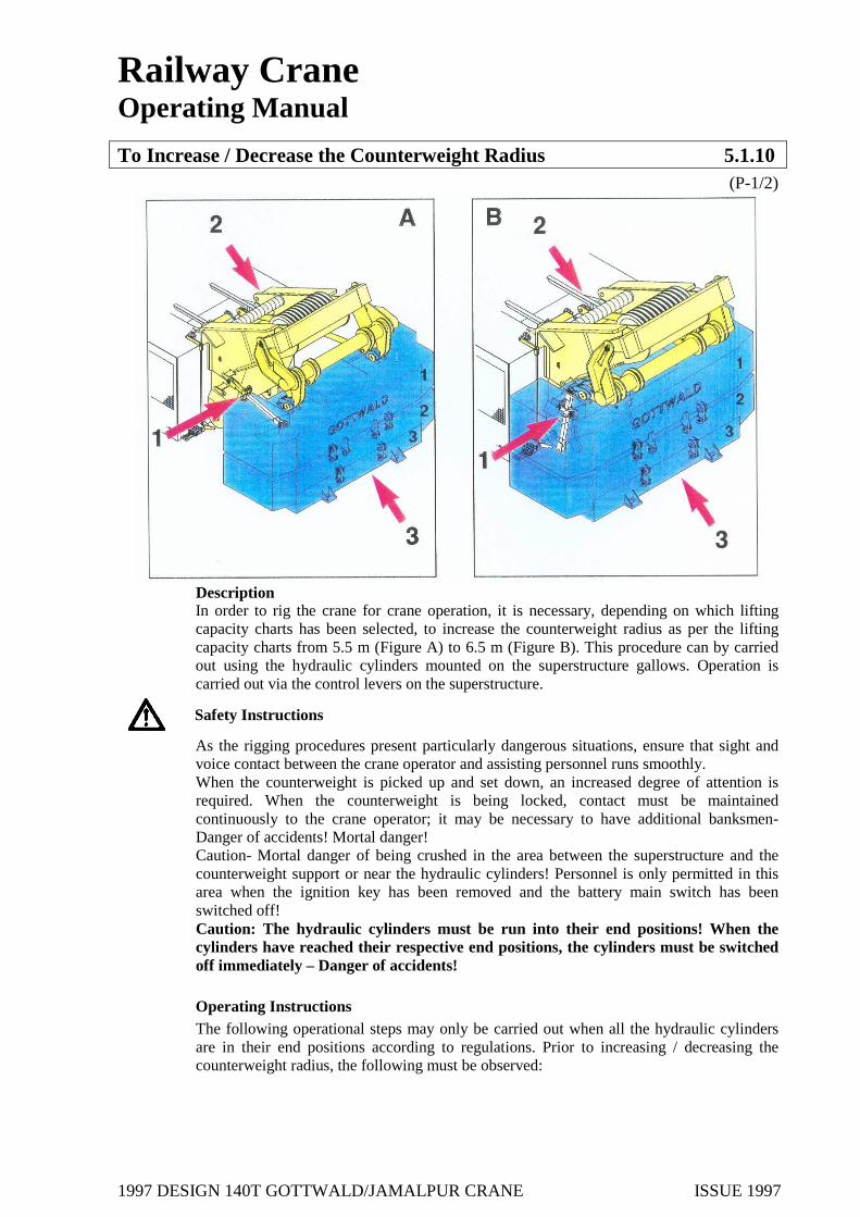
Description In order to rig the crane for crane operation, it is necessary, depending on which lifting capacity charts has been selected, to increase the counterweight radius as per the lifting capacity charts from 5.5 m (Figure A) to 6.5 m (Figure B). This procedure can by carried out using the hydraulic cylinders mounted on the superstructure gallows. Operation is carried out via the control levers on the superstructure.
Safety Instructions
As the rigging procedures present particularly dangerous situations, ensure that sight and voice contact between the crane operator and assisting personnel runs smoothly. When the counterweight is picked up and set down, an increased degree of attention is required. When the counterweight is being locked, contact must be maintained continuously to the crane operator; it may be necessary to have additional banksmen- Danger of accidents! Mortal danger! Caution- Mortal danger of being crushed in the area between the superstructure and the counterweight support or near the hydraulic cylinders! Personnel is only permitted in this area when the ignition key has been removed and the battery main switch has been switched off! Caution: The hydraulic cylinders must be run into their end positions! When the cylinders have reached their respective end positions, the cylinders must be switched off immediately – Danger of accidents! Operating Instructions The following operational steps may only be carried out when all the hydraulic cylinders are in their end positions according to regulations. Prior to increasing / decreasing the counterweight radius, the following must be observed:
1997 DESIGN 140T GOTTWALD/JAMALPUR CRANE ISSUE 1997
Railway Crane Operating Manual
To Increase / Decrease the Counterweight Radius 5.1.10 (P-2/2)
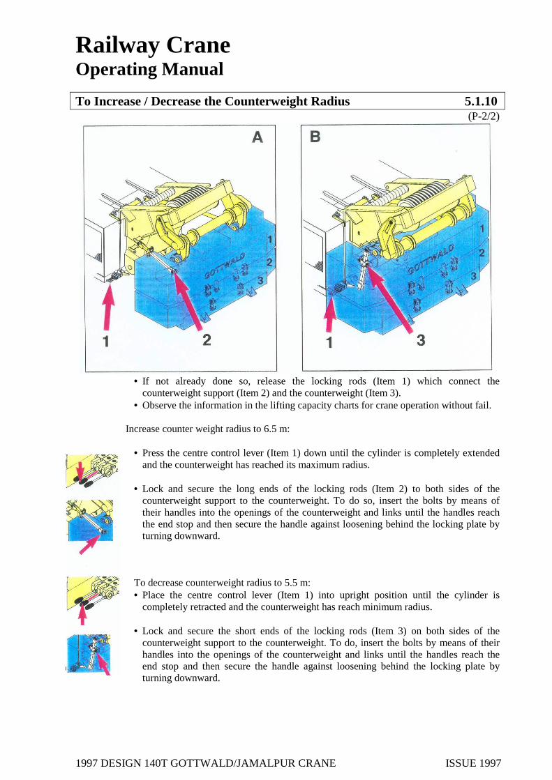
• If not already done so, release the locking rods (Item 1) which connect the
counterweight support (Item 2) and the counterweight (Item 3). • Observe the information in the lifting capacity charts for crane operation without fail.
Increase counter weight radius to 6.5 m:
• Press the centre control lever (Item 1) down until the cylinder is completely extended and the counterweight has reached its maximum radius.
• Lock and secure the long ends of the locking rods (Item 2) to both sides of the
counterweight support to the counterweight. To do so, insert the bolts by means of their handles into the openings of the counterweight and links until the handles reach the end stop and then secure the handle against loosening behind the locking plate by turning downward.
To decrease counterweight radius to 5.5 m: • Place the centre control lever (Item 1) into upright position until the cylinder is
completely retracted and the counterweight has reach minimum radius. • Lock and secure the short ends of the locking rods (Item 3) on both sides of the
counterweight support to the counterweight. To do, insert the bolts by means of their handles into the openings of the counterweight and links until the handles reach the end stop and then secure the handle against loosening behind the locking plate by turning downward.

1997 DESIGN 140T GOTTWALD/JAMALPUR CRANE ISSUE 1997
Railway Crane Operating Manual
Raise / Lower Boom 5.1.11 (P-1/4)
Description The boom can be lowered onto the boom support located on the match wagon coupled to the crane. In order to attain the necessary radius in curves, the boom fulcrum point must be extended forward from the superstructure.
Safety Instructions
As the rigging procedures present particularly dangerous situations, ensure that sight and voice contact between the crane operator and assisting personnel runs smoothly. Ensure that no one is near moving parts - Danger of being crushed or pulled into the equipment!
Operating Instructions The boom should not be lowered onto the match truck or be hoisted in curves, but rather only on straight sections.
For the rigging procedures, the boom must be run beyond the normal working position. To so do, press the button on the control lever (Item 1). The button is designed in such a way that it switches automatically to “Off” when it retracts into normal working range, i.e. when the normal working range must be exceeded, the button must be re-activated.
To raise the boom, the following operating steps in the indicated sequence must be observed.
It is assumed that the diesel engine is running, the counterweight support is erected, the suspension blocking is switched on and the selector lever for the hydraulics is in “center position”.

1997 DESIGN 140T GOTTWALD/JAMALPUR CRANE ISSUE 1997
Railway Crane Operating Manual
Raise / Lower Boom 5.1.11 (P-2/4)
1. Unlock the boom head on the match truck Boom support manually. 2. Pull back the control lever (Item 1) to “derrick in”.
Caution – tension the ropes for the main hoist and auxiliary hoist hook at the same via the right hand control lever by “hoisting”! Derrick in the boom until the boom is rigid-mounted in the fulcrum point. At the same time, the boom head is moved completely forward out of the support block.
3. “Derrick in “the boom further. Ensure that the rope retainer rod on the
Match truck is removed. Derrick in boom until it is least in its lowest working position. Caution – Watch the main hoist and auxiliary hoist hook ropes.
4. Release the brackets on the main and auxiliary hoist hook blocks and raise
the hoist ropes until the hook blocks are suspended freely.
1997 DESIGN 140T GOTTWALD/JAMALPUR CRANE ISSUE 1997
Railway Crane Operating Manual
Raise / Lower Boom 5.1.11 (P-3/4)
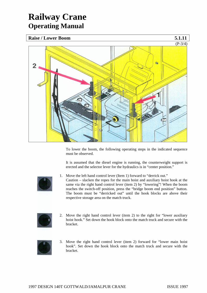
To lower the boom, the following operating steps in the indicated sequence must be observed. It is assumed that the diesel engine is running, the counterweight support is erected and the selector lever for the hydraulics is in “center position.”
1. Move the left hand control lever (Item 1) forward to “derrick out.” Caution – slacken the ropes for the main hoist and auxiliary hoist hook at the same via the right hand control lever (item 2) by “lowering”! When the boom reaches the switch-off position, press the “bridge boom end position” button. The boom must be “derricked out” until the hook blocks are above their respective storage area on the match truck.
2. Move the right hand control lever (item 2) to the right for “lower auxiliary hoist hook.” Set down the hook block onto the match truck and secure with the bracket.
3. Move the right hand control lever (item 2) forward for “lower main hoist hook”. Set down the hook block onto the match truck and secure with the bracket.

1997 DESIGN 140T GOTTWALD/JAMALPUR CRANE ISSUE 1997
Railway Crane Operating Manual
Raise / Lower Boom 5.1.11 (P-4/4)
4. Move the left hand control lever forward “to derrick out”.
Caution – At the same time, tension the main hoist and auxiliary hoist hook ropes by “hoisting” via the right hand control lever ((item 2). Lay the rope retainer bar on the match truck between the main hoist and auxiliary hoist ropes.
5. Lower the boom again until the guide bolts on the boom head are on the boom support on the match truck.
6. Caution – slacken the derricking ropes as well as the main hoist and auxiliary hoist ropes. The boom moves further forward during the next work step!
7. Activate the foot button (item 3) in the cab. The boom is thus pushed further forward form the boom fulcrum point via the hydraulic cylinders. At the same time, the bolts on the boom head slide into the guide on the boom support block on the match truck.
8. Check for proper locking on the boom support block.

1997 DESIGN 140T GOTTWALD/JAMALPUR CRANE ISSUE 1997
Railway Crane Operating Manual
Retract the Main Hoist Hook Block to the Boom 5.1.12 (P-1/2)
Description
To optimise certain lifting capacities, the main hoist hook block must be retracted to the boom (Observe the lifting capacity charts!)
Safety Instructions
As the rigging procedures present particularly dangerous situations, ensure that sight and voice contact between the crane operator and assisting personnel runs smoothly. Ensure that no one is near moving parts- Danger of being crushed or pulled into the equipment! Use caution near the swinging hook block- Danger of accidents! You may only climb up onto the crane to attach the tensioning ropes on to the hook block. The crane must be switched off while this activity is carried out. Operating Instructions To retract the main hoist hook block to the boom: 1. To move boom to its steepest position:
*Activate the luffing gear and main hoist until the main hoist hook block is in front of the cab. When the steepest boom position has been reached, press the button on the left hand control lever while derricking the bridge the end position. Caution- Do not exceed the ultimate end position after bridging –Danger of accident!
2. To attach the main hoist hook block:
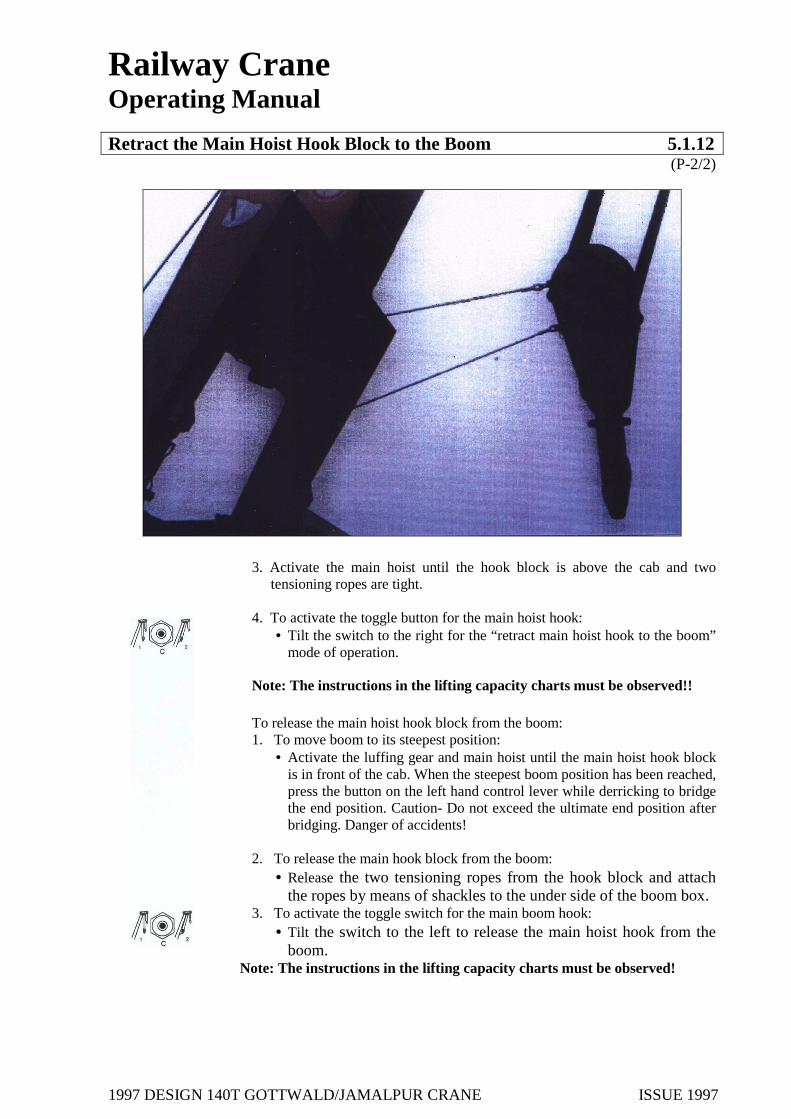
*Release the two tensioning ropes (Item 1) on the under side of the boom box and attach to the main hoist hook block by means of shackles.
1997 DESIGN 140T GOTTWALD/JAMALPUR CRANE ISSUE 1997
Railway Crane Operating Manual Retract the Main Hoist Hook Block to the Boom 5.1.12
(P-2/2)
3. Activate the main hoist until the hook block is above the cab and two tensioning ropes are tight.
4. To activate the toggle button for the main hoist hook:
• Tilt the switch to the right for the “retract main hoist hook to the boom” mode of operation.
Note: The instructions in the lifting capacity charts must be observed!! To release the main hoist hook block from the boom: 1. To move boom to its steepest position:
• Activate the luffing gear and main hoist until the main hoist hook block is in front of the cab. When the steepest boom position has been reached, press the button on the left hand control lever while derricking to bridge the end position. Caution- Do not exceed the ultimate end position after bridging. Danger of accidents!
2. To release the main hook block from the boom:
• Release the two tensioning ropes from the hook block and attach the ropes by means of shackles to the under side of the boom box.
3. To activate the toggle switch for the main boom hook: • Tilt the switch to the left to release the main hoist hook from the
boom. Note: The instructions in the lifting capacity charts must be observed!

1997 DESIGN 140T GOTTWALD/JAMALPUR CRANE ISSUE 1997
Railway Crane Operating Manual
Start-up Requirements 5.2 (P-1/1)
5.2.1 Hydraulics 5.2.2 Diesel Engine System 5.2.3 Battery Main Switch 5.2.4 Fuel Supply 5.2.5 Undercarriage Hydraulics On/Off 5.2.6 Ropes 5.2.7 Hoist and Lowering Limit Switches 5.2.8 Boom Length Sensor, Angle Sensor 5.2.9 Emergency Diesel Engine

1997 DESIGN 140T GOTTWALD/JAMALPUR CRANE ISSUE 1997
Railway Crane Operating Manual
Hydraulics 5.2.1 (P-1/1)
Description
The hydraulic system is driven by the diesel engine via a pump distributor gearbox. It must be ensured without fail that the hydraulics function properly in crane and in travel operation under own power.
Safety Instructions
Leakages or any other malfunctions on the hydraulic system may only be remedied by the respective specialist personnel.
Operating Instructions
Visual check: • Check the hydraulic oil tanks and its connections for external damage and
leakages. • Read off the oil level on the oil level indicator. The oil level should also be
read off later when the crane in at operating temperature. The maximum oil level has been reached when all the cylinders have been retracted. The oil must not fall below the minimum oil level when all the cylinders have been extended.
• Check the hydraulic system for leakages. • The cock stops must be open.
Check:
• Check whether the temperature for the hydraulic oil is too high. If the temperature is too high, the control lamp illuminates.
1997 DESIGN 140T GOTTWALD/JAMALPUR CRANE ISSUE 1997
Railway Crane Operating Manual
Diesel Engine System 5.2.2 (P-1/1)
Description
The diesel engine system drives the hydraulic pumps for travel and crane operations via the pump distributor gearbox. The diesel engine also supplies the air pressure system with air pressure via the its direct – mounted air compressor, as well as power to the batteries and thus the electric system via its direct-mounted 3- phase generator. The diesel engine is an air- cooled 6-cylinders, 4- cycle diesel engine with direct injection and exhaust turbo charger.
Safety Instructions
Prior to commencing check work on the crane, remove the ignition key from the cab and
affix a respective “check work’ sign.
Operating Instructions 1. Visual check:
Check the diesel engine for visible damage and external leakages. 2. Oil level:
Check the oil level on the oil dipstick. The exact oil level can first be read off after the engine has been at a stand still at least 10 minutes. Caution! – Some engines have two markings, one for idling and one for stand still. Ensure to read off the correcting marking.
The following points should be recorded by the crane operator and reported to the maintenance personnel: 1. Engine oil pressure too low 2. Low output 3. Excessive cylinder head and oil temperatures 4. Unusual noises 5. Heavy smoke 6. Above average consumption of coolant, fuel or lubricating oil. 7. Leakage in the fuel or lubricating systems.

1997 DESIGN 140T GOTTWALD/JAMALPUR CRANE ISSUE 1997
Railway Crane Operating Manual
Battery Main Switch 5.2.3 (P-1/1)
Description
By means of the battery main switch, the power supplied to the batteries can be cut off. This means that, for example, the diesel engine can be started up when the main battery switch is switched on. The crane has a separate battery main switch for the diesel and emergency diesel engines respectively.
Safety Instructions The battery main switches can be secured by removing the key for safekeeping.
Operating Instructions
The operation of both battery main switches is identical:
To switch: “ON” the battery main switch: • To switch On, insert the main switch key and turn 900.
To switch “OFF” the battery main switch:
• To switch “OFF” turn the main switch key 900 and remove.

1997 DESIGN 140T GOTTWALD/JAMALPUR CRANE ISSUE 1997
Railway Crane Operating Manual
Fuel Supply 5.2.4 (P-1/1)
Description
The diesel fuel tank supplies the fuel required for the diesel engines. The tank is integrated in the steel construction of the superstructure. The fuel capacity is approx. 900 I.
Safety Instructions
The fuel tank should not be completely run empty under any circumstances as subsequent bleeding and re-commissioning the diesel engine as a result necessitates a great deal of time and effort. In addition, it should be ensured that the fuel supply is sufficient to carry out the scheduled job as a dangerous situation could be caused under certain circumstances if the diesel engine were to come to a standstill. Caution – Fuel is inflammable! Naked light and smoking are prohibited when work is being performed near fuel- related parts.
Operating Instructions
The fuel supply is displayed in the cab. There should always be sufficient fuel for the scheduled job for the day.
The fuel consumption based on an average job operation is as follows:
Fuel consumption approx. 200- 220 kW / hr.
i.e., at full speed : 45 L / hr. half speed : 20-25 LI / hr.
Never run the tank until it is empty as this involves time- intensive cleaning and bleeding work before it can be re-used.
1997 DESIGN 140T GOTTWALD/JAMALPUR CRANE ISSUE 1997
Railway Crane Operating Manual
Undercarriage Hydraulics “On/ Off” 5.2.5 (P-1/1)
Description
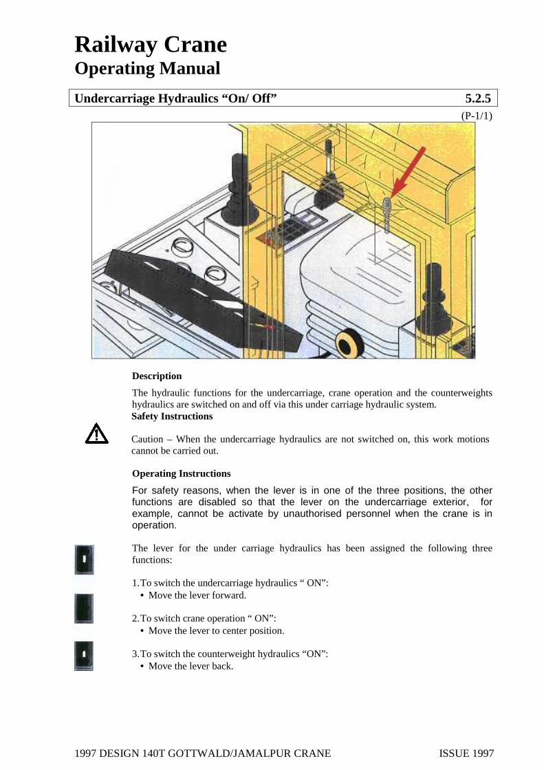
The hydraulic functions for the undercarriage, crane operation and the counterweights hydraulics are switched on and off via this under carriage hydraulic system.
Safety Instructions Caution – When the undercarriage hydraulics are not switched on, this work motions cannot be carried out.
Operating Instructions
For safety reasons, when the lever is in one of the three positions, the other functions are disabled so that the lever on the undercarriage exterior, for example, cannot be activate by unauthorised personnel when the crane is in operation. The lever for the under carriage hydraulics has been assigned the following three functions:
1. To switch the undercarriage hydraulics “ ON”:
• Move the lever forward. 2. To switch crane operation “ ON”:
• Move the lever to center position.
3. To switch the counterweight hydraulics “ON”: • Move the lever back.

1997 DESIGN 140T GOTTWALD/JAMALPUR CRANE ISSUE 1997
Railway Crane Operating Manual
Ropes 5.2.6 (P-1/1)
Description
The ropes must run properly and safety on the rope drums, the rope pulleys and the guides to provide safety crane operation. The ropes must be in defect-free condition. Damage ropes can cause accidents.
Safety Instructions Work on the ropes may only be carried out by Special maintenance personnel. Caution near the overhead lines! – Do not climb up onto the crane superstructure. Mortal danger!
Operating Instructions
Check the ropes for external damage. In addition, ensure that the ropes coil properly on the drums and run through the rope pulleys and guides. Always carry out a functional test without load prior to crane operation.

1997 DESIGN 140T GOTTWALD/JAMALPUR CRANE ISSUE 1997
Railway Crane Operating Manual
Hoist and Lowering Limit Switches 5.2.7 (P-1/1)
Description
The hoist and lowering limit switches for the luffing gear, the main hoist and the auxiliary hoist are located on the face sides of the winches located on the diesel engine side.
Safety Instructions Caution near the over headlines! – Do not climb up onto the crane superstructure! Mortal danger! In the event of a limit switch malfunction, crane operation must be started or crane operation must be stopped immediately.
Operating Instructions
Prior to commencing with a job, check the limit switches for proper functioning. To so, approach the respective end position slowly and without load. Also check limit switches after bridging the boom end positions (see sections 5.6.2 / 5.1.11).

1997 DESIGN 140T GOTTWALD/JAMALPUR CRANE ISSUE 1997
Railway Crane Operating Manual
Angle Sensor 5.2.8 (P-1/1)
Description
The angle sensor to determine the boom angle when the boom is derricked in and out is located in the boom lower section. The angle sensor for the superstructure / undercarriage rotation angle is located near the rotary lead-through.
Safety Instructions Caution near the over headlines! - Do not climb up onto the crane superstructure! Mortal danger! In the event of a limit switch malfunction, crane operation must be started or crane operation must be stopped immediately.
Operating Instructions
Prior to commencing work, check the angle sensor for proper functioning. To do so, move the boom to the smallest and greatest radius slowing without load. At the same time, check whether the corresponding radius is indicated correctly on the display.

1997 DESIGN 140T GOTTWALD/JAMALPUR CRANE ISSUE 1997
Railway Crane Operating Manual
Emergency Diesel Engine 5.2.9 (P-1/1)
Description
The emergency diesel engine drives a tandem gear pump and a 3-phase generator during emergency operation. The diesel engine can be started up electrically or manually.
Safety Instructions In the event the emergency diesel engine is not operation, crane operation must not be started. Caution- fuel is inflammable! When work is carried out near fuel-related parts, fire, naked light and smoking are prohibited!
Operating Instructions Prior to commencing with the work, check the emergency diesel engine as to whether the diesel engine is operational. To do so, the following points should be checked:
Visual check:
Check the emergency diesel engine and the mounted hydraulic auxiliary pump and their caps for external damage and firm seating. Also check the emergency diesel engine for leakages.
Fuel Supply:
The diesel fuel for the emergency diesel engine is taken from the diesel engine fuel tank, making a repeated check of the fuel supply as per Section 5.2.4 redundant.
Lubricating Oil:
Check the engine oil lever on the oil dipstick. Control panel:
Check the control panel for external damage.
1997 DESIGN 140T GOTTWALD/JAMALPUR CRANE ISSUE 1997
Railway Crane Operating Manual
Emergency Diesel Engine 5.3 (P-1/1)
5.3.1 Start / Stop Emergency Diesel Engine

1997 DESIGN 140T GOTTWALD/JAMALPUR CRANE ISSUE 1997
Railway Crane Operating Manual
Start/ Stop Emergency Diesel Engine 5.3.1 (P-1/4)
Description
The emergency diesel engine drives a tandem gear pump and a 3- phase generator during emergency operation. The diesel engine can be started up electrically or manually. The 2- cylinder four-cycle diesel engine has a cubic capacity of 1,8843 and an output of 16.9 kW at 1,800 rpm.
The fuel is supplied via the fuel tank of the diesel engine system so that the tanks must have a corresponding supply for the operation of the emergency diesel engine.
In the event the Main Diesel Engine fails, the crane can be brought into transport position by means of the emergency diesel engine. The following motions can be carried
• slewing of the superstructure • hoisting and lowering motions using hoists but without load • lowering motions using hoists under load • lowering of counterweights • retraction / swing-in of the outriggers
Safety Instructions The emergency diesel engine may only be operated in emergency situation in the event of a diesel engine failure in order to allow the crane to be brought into transport position. In addition, the battery can be re-charged using the emergency diesel engine. The emergency diesel engine is not designed for regular crane operation and thus it is not permissible to use this engine for regular crane operation.
1997 DESIGN 140T GOTTWALD/JAMALPUR CRANE ISSUE 1997
Railway Crane Operating Manual
Start/ Stop Emergency Diesel Engine 5.3.1 (P-2/4)
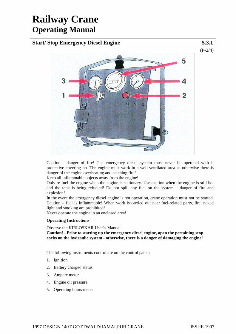
Caution - danger of fire! The emergency diesel system must never be operated with it protective covering on. The engine must work in a well-ventilated area as otherwise there is danger of the engine overheating and catching fire! Keep all inflammable objects away from the engine! Only re-fuel the engine when the engine is stationary. Use caution when the engine is still hot and the tank is being refueled! Do not spill any fuel on the system – danger of fire and explosion! In the event the emergency diesel engine is not operation, crane operation must not be started. Caution – fuel is inflammable! When work is carried out near fuel-related parts, fire, naked light and smoking are prohibited! Never operate the engine in an enclosed area!
Operating Instructions
Observe the KIRLOSKAR User’s Manual. Caution! - Prior to starting up the emergency diesel engine, open the pertaining stop cocks on the hydraulic system - otherwise, there is a danger of damaging the engine!
The following instruments control are on the control panel:
1. Ignition
2. Battery charged status
3. Ampere meter
4. Engine oil pressure
5. Operating hours meter
1997 DESIGN 140T GOTTWALD/JAMALPUR CRANE ISSUE 1997
Railway Crane Operating Manual
Start/ Stop Emergency Diesel Engine 5.3.1 (P-3/4)
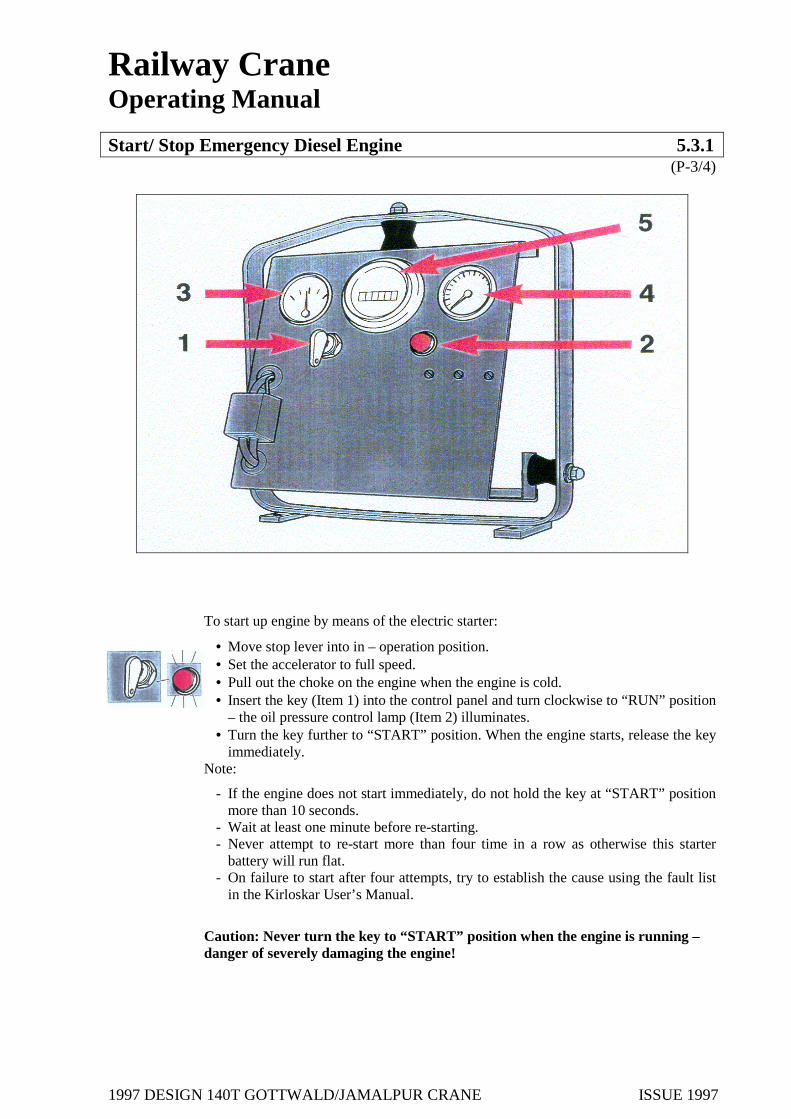
To start up engine by means of the electric starter:
• Move stop lever into in – operation position. • Set the accelerator to full speed. • Pull out the choke on the engine when the engine is cold. • Insert the key (Item 1) into the control panel and turn clockwise to “RUN” position
– the oil pressure control lamp (Item 2) illuminates. • Turn the key further to “START” position. When the engine starts, release the key
immediately. Note:
- If the engine does not start immediately, do not hold the key at “START” position more than 10 seconds.
- Wait at least one minute before re-starting. - Never attempt to re-start more than four time in a row as otherwise this starter
battery will run flat. - On failure to start after four attempts, try to establish the cause using the fault list
in the Kirloskar User’s Manual.
Caution: Never turn the key to “START” position when the engine is running – danger of severely damaging the engine!

1997 DESIGN 140T GOTTWALD/JAMALPUR CRANE ISSUE 1997
Railway Crane Operating Manual
Not - Diesel Start / Stop 5.3.1 (P-4/4)
To start up the engine manually:
• Move stop lever into in-operation position. • Set the accelerator to full speed. • Pull out the choke on the engine when the engine is cold. • Insert the key into the control panel and turn to “OFF” position. • Set both decompression levers in vertical position to “START”. • Mount the crank on the shaft of the emergency diesel engine and turn in arrow
direction (clockwise) until the engine starts. • When the engine has been started, set the decompression levers in horizontal
position one after the other. • Set the key of the electric start to “RUN” position.
To stop the engine:
• Never stop the emergency diesel engine directly after full-speed operation. • Allow the engine idle 2 to 3 minutes unloaded. • Then set the stop lever to “STOP” position. Do not release the stop lever until
the emergency diesel engine has come to a complete standstill. • Move the stop lever to in-operation position.

1997 DESIGN 140T GOTTWALD/JAMALPUR CRANE ISSUE 1997
Railway Crane Operating Manual
Diesel Engine System 5.4
(P-1/1) 5.4.1 “Start / In- operation / Stop” Diesel Engine 5.4.2 Accelerator

1997 DESIGN 140T GOTTWALD/JAMALPUR CRANE ISSUE 1997
Railway Crane Operating Manual
Start/ In –operation/ Stop Diesel Engine 5.4.1
(P-1/5)
Description
The diesel engine drives the hydraulic pumps for travel and crane operations via the pump distributor gearbox.
The diesel engine is an air-cooled 6 -cylinders, four-cycle diesel engine with direct injection and turbo charged cooling.
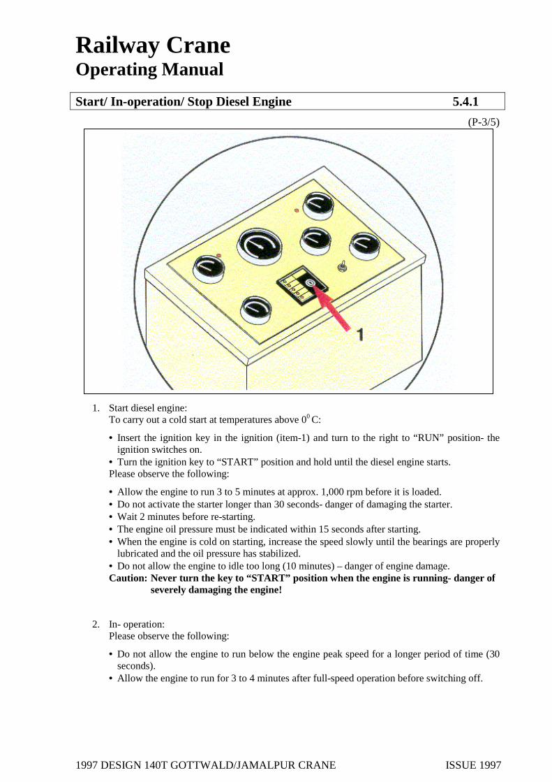
The control panel for the diesel engine is located in the cab on the front right hand side (see figure)
Safety Instructions It must be ensured that the crane cannot be switched on unknowingly. Remove ignition key and battery main switch and store in safekeeping to prevent unauthorised re-starting.
The diesel engine system and the emergency diesel engine must not be operated in an enclosed area- Danger of asphyxiation due to the exhaust fumes!
Never leave the crane untended when the diesel engine is running.
The crane must not be in the way of other vehicles.
Prior to starting, ensure there is sufficient fuel.
Operating Instructions
Observe the Cummins User’s Manual
1997 DESIGN 140T GOTTWALD/JAMALPUR CRANE ISSUE 1997
Railway Crane Operating Manual
Start/ In –operation/ Stop Diesel Engine 5.4.1
(P-2/5)
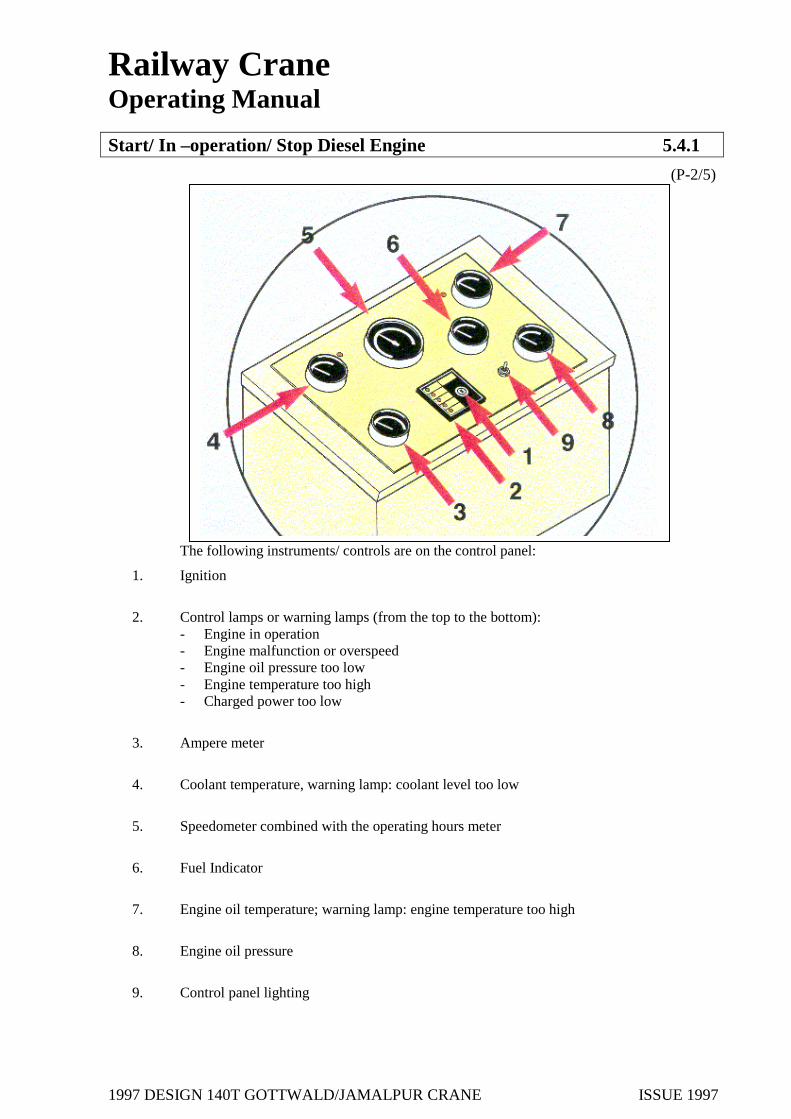
The following instruments/ controls are on the control panel:
1. Ignition
2. Control lamps or warning lamps (from the top to the bottom): - Engine in operation - Engine malfunction or overspeed - Engine oil pressure too low - Engine temperature too high - Charged power too low
3. Ampere meter
4. Coolant temperature, warning lamp: coolant level too low
5. Speedometer combined with the operating hours meter
6. Fuel Indicator
7. Engine oil temperature; warning lamp: engine temperature too high
8. Engine oil pressure
9. Control panel lighting
1997 DESIGN 140T GOTTWALD/JAMALPUR CRANE ISSUE 1997
Railway Crane Operating Manual
Start/ In-operation/ Stop Diesel Engine 5.4.1
(P-3/5)
1. Start diesel engine:
To carry out a cold start at temperatures above 00 C:
• Insert the ignition key in the ignition (item-1) and turn to the right to “RUN” position- the ignition switches on.
• Turn the ignition key to “START” position and hold until the diesel engine starts. Please observe the following:
• Allow the engine to run 3 to 5 minutes at approx. 1,000 rpm before it is loaded. • Do not activate the starter longer than 30 seconds- danger of damaging the starter. • Wait 2 minutes before re-starting. • The engine oil pressure must be indicated within 15 seconds after starting. • When the engine is cold on starting, increase the speed slowly until the bearings are properly
lubricated and the oil pressure has stabilized. • Do not allow the engine to idle too long (10 minutes) – danger of engine damage. Caution: Never turn the key to “START” position when the engine is running- danger of
severely damaging the engine!
2. In- operation: Please observe the following:
• Do not allow the engine to run below the engine peak speed for a longer period of time (30 seconds).
• Allow the engine to run for 3 to 4 minutes after full-speed operation before switching off.

1997 DESIGN 140T GOTTWALD/JAMALPUR CRANE ISSUE 1997
Railway Crane Operating Manual
Start/ In –operation/ Stop Diesel Engine 5.4.1
(P-4/5)
• Watch the oil pressure and coolant temperature indicators during operation and / or take into account the engine alarm function; if required, switch off the engine and eliminate problem.
• Lengthy operation at low (below 600C) or high (above 1000C) coolant temperatures can cause damage to the engine.
• If the engine threatens to overheat, reduce gas until the temperature remains in the normal operating range; otherwise, switch off the engine.
• Watch for early warning signs and if required take required measures. Early warning signs include:
- Misstarting, misfiring, backfiring - Excessive smoke - Shocks - Loss in power - Unusual engine noises - Increase oil consumption - Fuel, oil or coolant leakages - Increase fuel consumption - Sudden operating temperature or pressure fluctuations -
Note: In the event the engine alarm sounds (item 2, 4, 7) switch off the diesel engine immediately and eliminate the cause for the alarm. On exiting the crane cab, always switch off the diesel engine; remove the ignition key and store for safekeeping to prevent unauthorized re-starting.

1997 DESIGN 140T GOTTWALD/JAMALPUR CRANE ISSUE 1997
Railway Crane Operating Manual
Start/ In –operation/ Stop Diesel Engine 5.4.1
(P-5/5)
3. To stop the diesel engine: • Turn the ignition key (item 1) to “OFF” position and remove
Please observe the following:
• Allow the engine to run 3 to 5 minutes before switching off. • Do not allow the engine to idle too long. • Do not allow the ignition to remain switched on after the engine has been
switched off- Danger of engine damage through fuel running in from the fuel tank after the engine has been switched off.
4. Coolant Temperature: • An additional control lamp to indicate that the coolant temperature is too high is
located on the right hand control panel (Figure on the right hand side, item 2).

1997 DESIGN 140T GOTTWALD/JAMALPUR CRANE ISSUE 1997
Railway Crane Operating Manual
Accelerator 5.4.2
(P-1/1)
Description
The diesel engine speed is regulated by means of the foot-operated pedal for the accelerator. Thus, the speed can be adjusted smoothly for all travel and crane motions.
Safety Instructions
Caution! - Never store objects in the cab foot area. Any objects in this area could slide below or on the foot-operated pedals and cause a dangerous situation!
Caution! Only start travel operation when the parking brake has been completely released! - Do not begin to travel when the crane brake is applied.
Operating Instructions
The end speeds for the working motions are not only depending on how the foot-operated pedal is activated, but also on what speed has been selected via the respective control lever (see 5.5.1 and 5.6.1).
To increase speed: Depress the foot-operated at the front
To decrease speed: Release the foot –pedal.

1997 DESIGN 140T GOTTWALD/JAMALPUR CRANE ISSUE 1997
Railway Crane Operating Manual
Travel Operation 5.5
(P-1/1) 5.5.1 Travel Forwards / In Reverse 5.5.2 Brake

1997 DESIGN 140T GOTTWALD/JAMALPUR CRANE ISSUE 1997
Railway Crane Operating Manual
Travel Forwards/ In Reverse 5.5.1
(P-1/2)
Description
The crane has a changeover switch to change travel direction. This means that the travel lever motion always corresponds to the current sitting position. Thus, if the superstructure is rotated on the undercarriage, the travel lever motion is reversed when the superstructure is at approx 900 to the undercarriage.
Safety Instructions Caution! - The crane may only be traveled when the superstructure is in longitudinal position. Rotating the superstructure during travel or travel with the superstructure in transverse position is prohibited! Reverse travel direction! Caution! - When the Bowden cables have been activated, renewed braking action cannot be carried out until the brake system has been pressurised with air pressure. Before the parking brake is released, start up the crane and secure crane with the service brake. On exiting the crane, always apply the parking brake.
Caution! Only start travel operation when the parking brake has been completely released! - Do not begin to travel when the crane brake is applied.
Operating Instructions
The crane may be travel forwards or in reverse with or without load. The travel control lever is assigned the double function “Travel forwards/ reverse.”
1997 DESIGN 140T GOTTWALD/JAMALPUR CRANE ISSUE 1997
Railway Crane Operating Manual
Travel Forwards/ In Reverse 5.5.1
(P-2/2)
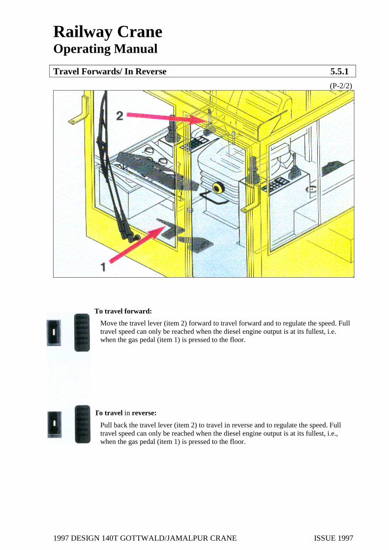
To travel forward:
Move the travel lever (item 2) forward to travel forward and to regulate the speed. Full travel speed can only be reached when the diesel engine output is at its fullest, i.e. when the gas pedal (item 1) is pressed to the floor.
To travel in reverse:
Pull back the travel lever (item 2) to travel in reverse and to regulate the speed. Full travel speed can only be reached when the diesel engine output is at its fullest, i.e., when the gas pedal (item 1) is pressed to the floor.
1997 DESIGN 140T GOTTWALD/JAMALPUR CRANE ISSUE 1997
Railway Crane Operating Manual
Brake 5.5.2
(P-1/1)
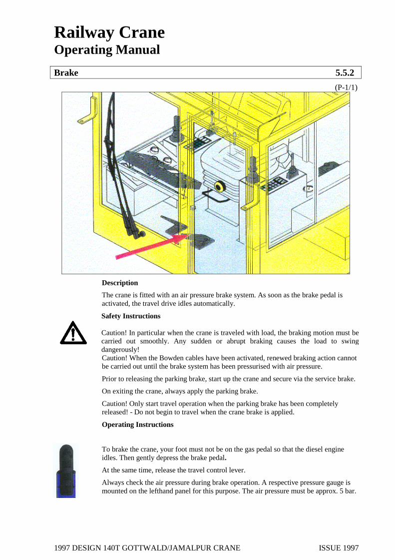
Description
The crane is fitted with an air pressure brake system. As soon as the brake pedal is activated, the travel drive idles automatically.
Safety Instructions Caution! In particular when the crane is traveled with load, the braking motion must be carried out smoothly. Any sudden or abrupt braking causes the load to swing dangerously! Caution! When the Bowden cables have been activated, renewed braking action cannot be carried out until the brake system has been pressurised with air pressure.
Prior to releasing the parking brake, start up the crane and secure via the service brake.
On exiting the crane, always apply the parking brake.
Caution! Only start travel operation when the parking brake has been completely released! - Do not begin to travel when the crane brake is applied.
Operating Instructions
To brake the crane, your foot must not be on the gas pedal so that the diesel engine idles. Then gently depress the brake pedal.
At the same time, release the travel control lever.
Always check the air pressure during brake operation. A respective pressure gauge is mounted on the lefthand panel for this purpose. The air pressure must be approx. 5 bar.

1997 DESIGN 140T GOTTWALD/JAMALPUR CRANE ISSUE 1997
Railway Crane Operating Manual
Crane Operation 5.6
(P-1/1) 5.6.1 Slew Right/ Left 5.6.2 Derrick in / out 5.6.3 Hoist/Lower using Main Hoist 5.6.4 Hoist/Lower using Auxiliary Hoist 5.6.5 Lifting Beams and Slings

1997 DESIGN 140T GOTTWALD/JAMALPUR CRANE ISSUE 1997
Railway Crane Operating Manual
Derrick In / Out 5.6.2
(P-1/2)
Description The boom position can be altered by means of the derricking gear. The winch, the rope drum, gearbox and drive assembly are located on the superstructure. When the boom is derricked out, the derricking gear uncoils the rope and moves the boom into its greatest radius. When the boom is derricked in, the derricking gear coils the rope and moves the boom into steepest position. Both end positions are monitored by means of the limit switches, which switch off operation automatically when the boom reaches the end positions.
For the rigging purposes, the end switch – off positions of the normal working range must be bridged by pressing the button on the control lever. The end positions (ultimate end positions) in rigging operation are also monitored by limit switches, which switch off operation automatically when the boom reaches the end positions. The boom position is sensed via the angle sensor. This data forms the basis for the lifting capacity charts.
The derricking gear is operated by means of the control lever in the cab.
Safety Instructions
During crane operation, always ensure that no persons or obstacles are in the working or danger zones.
Watch for train traffic on adjacent tracks- Danger of Accidents!
Do not stand or move below suspended loads – Mortal danger!
Caution!- observe the load indicator! In the event the load indicator or safe load indicator failure, crane operation must not be started or must be stopped immediately!
The crane may only be propped at the propping bases indicated in the Technical Data. The ground must withstand the propping pressures. Use caution near the overhead lines- Mortal danger!

1997 DESIGN 140T GOTTWALD/JAMALPUR CRANE ISSUE 1997
Railway Crane Operating Manual
Derrick In / Out 5.6.2
(P-2/2)
Keep out of slewing range! Loads must be lifted vertically. Diagonal pull is prohibited. The limit switches may only be bridged for rigging and not other purposes!
During crane operation, bridging the boom position limit switches is prohibited! Rigging must also be carried out in connection with a competent banksman.
Operating Instructions
When work is carried out near bridges, masts and overhead lines, the working height is restricted as otherwise there is a danger of the boom colliding with the overhead line – Use a banksman!
The control lever for the derricking motion is a combined function lever for the functions “slew right/ left” and “derrick in /out”.
To derrick in:
• Pull back control lever.
To derrick out:
• Move control lever forward.
Note: When the control lever is released, it returns to center position.
To bridge the boom end position:
• Press button on the control lever.

1997 DESIGN 140T GOTTWALD/JAMALPUR CRANE ISSUE 1997
Railway Crane Operating Manual
Hoist / Lower Using Main Hoist 5.6.3 (P-1/2)
Description
The crane is fitted with two hoists which work independently of one another. The main hoist lifts and lowers the ramshorn hook. You may select normal speed or high - speed to hoist and lower small and medium-sized loads in the range below full load.
Safety Instructions
During crane operation, always ensure that no persons or obstacles are in the working or danger zones. Caution- observe the load indicator! In the event the load indicator or safe load indicator failure, crane operation must not be started or must be stopped immediately!
Caution the high-speed gear may only be used to hoist and lower small and medium-sized
loads in the range below full load - Do not use this gear for any other purpose!
During crane operation in high-speed gear, watch the rope drum of the main hoist. If the rope is not properly coiled or the rope slackens during lowering, stop the hoist; if required, re-coil ropes properly and proceed with work at normal speed as otherwise there is a danger of rope damage and accidents.

1997 DESIGN 140T GOTTWALD/JAMALPUR CRANE ISSUE 1997
Railway Crane Operating Manual
Hoist / Lower Using Main Hoist 5.6.3 (P-2/2)
Operating Instructions The “hoist/lower” control lever is a combined function lever for the functions “hoist/lower using main hoist” or “hoist/lower using auxiliary hoist”. To change over from normal to high-speed gear, press the pushbutton on the control lever.
The lever motion for the main hoist corresponds to rope motion: To hoist using the main hoist:
• Pull back control lever. To lower using the main hoist:
• Move control lever forward. To switch to high-speed gear:
• Press the button on the control lever and keep depressed. To switch off the high-speed gear:
• Release the button on the control lever. Note: - After the button has been released, the control lever returns to center position.

1997 DESIGN 140T GOTTWALD/JAMALPUR CRANE ISSUE 1997
Railway Crane Operating Manual
Hoist/ Lower Using Auxiliary Hoist 5.6.4 (P-1/2)
Description
The crane is fitted with two hoists which work independently of one another. The auxiliary hoist lifts and lowers the single hook.
You may select normal speed or high-speed to hoist and lower small and medium-sized loads in the range below full load.
Safety Instructions
During crane operation, always ensure that no persons or obstacles are in the working or danger zones. Caution- observes the load indicator! In the event the load indicator or safe load indicator failure, crane operation must not be started or must be stopped immediately!
Caution the high-speed gear may only be used to hoist and lower small and medium-sized loads in the range below full load - Do not use this gear for any other purpose!
During crane operation in high- speed gear, watch the rope drum of the main hoist. If the rope is not properly coiled or the rope slackens during lowering, stop the hoist; if required, re-coil ropes properly and proceed with work at normal speed as otherwise there is a danger of rope damage and accidents.

1997 DESIGN 140T GOTTWALD/JAMALPUR CRANE ISSUE 1997
Railway Crane Operating Manual
Hoist/ Lower Using Auxiliary Hoist 5.6.4 (P-2/2)
Operating Instructions The “hoist/lower” control lever is combined function lever for the functions “hoist/lower using auxiliary hoist” or “hoist /lower using main hoist”. To change over from normal to high-speed gear, press the pushbutton on the control lever. The lever motion for the auxiliary hoist is as follows: To hoist using the auxiliary hoist:
• Move control lever to the left. To lower using the auxiliary hoist:
• Move control lever to the right. To switch to high –speed gear
• Press the button on the control lever and keep depressed. To switch off the high-speed gear:
• Release the button on the control lever. Note: After the button has been released, the control lever returns to center position.

1997 DESIGN 140T GOTTWALD/JAMALPUR CRANE ISSUE 1997
Railway Crane Operating Manual
Lifting Beams and Slings 5.6.5 (P-1/2)
Description
Two lifting beams (max. lifting capacities being 70 t or 140 t according to their two signs respectively; see figure above) as well as various slings and chains have been supplied.
Safety Instructions
Prior to attaching the lifting beams and slings/chains, check them for external damage. The lifting beams and slings/chains may only be used when operating safety has been ensured. Use only original parts for lifting purposes. The lifting beams may only be operated with the wedge tensioning device as laid down by regulations. Lifting beam bolts are secured with cotter pins. Use caution when the lifting beams are mounted and operated - Danger of being crushed or drawn into the equipment. Ensure that the bolt connection is firmly seated. An improperly mounted lifting beam or a suspended load on an improperly mounted lifting beam can cause serious accidents - Danger of accidents! Mortal danger! No persons may convey on a lifting beams or on a load suspended from a lifting beam - Mortal danger! Stay out of the range of lifting beams or suspended loads. The maximum loading for the lifting beams and for the individual slings and chains must not be exceeded.

1997 DESIGN 140T GOTTWALD/JAMALPUR CRANE ISSUE 1997
Railway Crane Operating Manual
Lifting Beams and Slings 5.6.5 (P-2/2)
Operating Instructions Lifting Beam (see figure above):
Both lifting beams are attached in the same manner: 1. Lower the hook to the lifting beam (1) so that the lifting beam can be attached to the hook
by means of the pin-and–bolt connections. 2. Insert the bolts until they reach the end stop through the opening in the lifting beams and
hook (2) and then turn them behind the links to secure against loosening (3). Note: To set down the lifting beam, proceed in reverse sequence. Slings and chains (not shown): When loads are being attached, observe the instructions on safety and use posted on the signs mounted on the slings and chains.

1997 DESIGN 140T GOTTWALD/JAMALPUR CRANE ISSUE 1997
Railway Crane Operating Manual
General Operating Functions 5.7 (P-1/1)
5.7.1 Safe load Indicator 5.7.2 Lighting 5.7.3 Signal Horns 5.7.4 Screen/Wiper System 5.7.5 Fans 5.7.6 Seat 5.7.7 Parking Crane Safely 5.7.8 Safe load Indicator Emergency Operation 5.7.9 Additional Equipment 5.7.10 Recovery Winch

1997 DESIGN 140T GOTTWALD/JAMALPUR CRANE ISSUE 1997
Railway Crane Operating Manual
Safe Load Indicator 5.7.1 (P-1/6)
The railway crane is secured during crane operation against overload by means of an electronic safe load indicator (SLI). This means that motion which increase the load moment during crane work are switched off.
The following factors are taken into account for the safe load indicator: 1. Propping base 2. Boom angle 3. Slewing angle 4. Load 5. Counterweight configuration 6. Counterweight radii: 5.5 m / 6.5m. 7. Main hoist hook block is retracting to / released from the boom. The figures (2-4) can be displayed on the safe load indicator display in the cab.
Safety Instructions
The safe load indicator is an automatic switch-off system in the event of an emergency situation. Always check the safe load indicator for proper functioning and the data it displays. Should the data appear unrealistic, there may by, for example, malfunctioning sensors which cannot be detected by the system itself. Have the safe load indicator checked immediately by specially trained personnel. The safe load indicator is to be tested by authorised personnel at the intervals set down by law - however, at least once a year. The safe load indicator is designed as an aid to the crane operator and should not be used carelessly. The figures in the lifting capacity charts are decisive for operation.

1997 DESIGN 140T GOTTWALD/JAMALPUR CRANE ISSUE 1997
Railway Crane Operating Manual
Safe Load Indicator 5.7.1 (P-2/6)
Please also note that improper operating techniques and inadmissible job conditions cannot be sensed by the system and therefore, the safe load indicator will switch off too late:
• Under slinging the load or the lifting gear • Pendulous swinging of the load • Breaking loose of loads which are struck • Loads falling into the rope • Diagonal pull • Non-vertical lifting of loads • Lifting inadmissibly heavy loads by derricking in the boom.
The SLI is fitted with a bridging switch which on activation switches off the control levers. This switch may only be used in emergency situations and may only be operated by authorised personnel. Non-observance of these instructions can cause damage and series or even mortal injuries!
Operating Instructions
The safe load indicator is operated via the panel in the cab. For further information, consult the PAT User’s Manual. To switch the safe load indicator from one lifting capacity chart to another, the following selector switches must be used: Item 11: Selector switch A: Propping base (Section 5.1.6), Item 12: Selector switch B: Counter weights (Section 5.1.4, 5.1.8, 5.1.9) Item 14: Selector switch C: Main hoist hook (Section 5.1.12), Item 15: Selector switch D: Counter weight radius (Section 5.1.10). Set the codes in accordance with the lifting capacity charts and the switch symbols on selector switches, A to D to rig, code 1-1-1-1 must be set.
Rigging may only be carried out in the sequence described below:
The actual rigging condition must be set on the safe load indicator directly after each rigging step has been carried out: 1: Set rigging code 1-1-1-1 on the safe load indicator. 2: Rig propping base (if required, for the selected lifting capacity chart) - then set rigging code
(selector switch A) 3: Select counterweight (if required, for the selected lifting capacity chart) - then set rigging cod
(selector switch B). 4: Select counterweight radius (if required, for the selected lifting capacity chart) - then set
rigging code (selector switch D) 5: Retract / releases main hoist hook block (if required, for the selected lifting capacity chart) -
then set rigging code (selector switch C).

1997 DESIGN 140T GOTTWALD/JAMALPUR CRANE ISSUE 1997
Railway Crane Operating Manual
Safe Load Indicator 5.7.1 (P-3/6)
Item 1: Load moment pre-warning light: The yellow load moment pre-warning light illuminates when the crane loading has reached 90% to 100% of the established pre-warning range. Caution: This means that the crane operator may only cautiously continue crane work!
Item 2: Overload warning lamp:
The red overload warning lamp shows the crane operator that an overload situation has occurred. The warning lamp illuminates when the crane loading has reached or exceeded 100% of the permissible maximum lifting capacity for the current mode of operation. At the same time, the crane motions which increase the load moment are switched off and an acoustic alarm sounds.
Item 3: “Buzzer off” button:
By activating the “buzzer off” button, the acoustic alarm can be suppressed for approx. 15 sec.
Item 4: Audible alarm: This module activates the audible alarm. Item 5: Load indicator:
The digital indicator shows the current load. The load type displayed depends on the position of the load selector switch.

1997 DESIGN 140T GOTTWALD/JAMALPUR CRANE ISSUE 1997
Railway Crane Operating Manual
Safe Load Indicator 5.7.1 (P-4/6)
Item 6: Load selector switch:
This rotary switch is used in connection with the load indicator to display the types of loads. • When the switch is turned to the left:
The rate load of crane in relation to the current crane work radius and the respective mode of operation are shown.
• When the switch is neutral position in the center: The total load is shown or when the lamp flashes the net load • When the switch is turned to the right:
The load is tared (set to zero). The switch is spring-loaded so it returns to neutral position after release. When the display flashes, the net load is shown. The display will changed back automatically to indicating the total load when the boom radius is altered, i.e. when the boom angle is altered. Note: The total weight includes the weight on the hook block, the hoist rope and all the lifting gear. The net load is the actual load on the hook block excluding the lifting gear. Display errors are possible due to external factors, e.g. wind acting on the crane and the load.
Item 7: Load moment display:
This instrument indicates how much of the crane rated capacity is being used. As the rated capacity of the crane changes as it is moved through its various emotions, the utilisation display will constantly change as well.
To provide a better display, the bar graph display has three sections: • green: “safe” range (0% to 90% of the rated capacity). • yellow: pre- warning range (90% to 100% of the rated capacity) • red: overload range (above 100% of the rated capacity)
Item 8: Boom data display:
This display provides information regarding the status of the operating geometry of the crane and possibly an error code. The data shown depends on the position of the selector switch.
Item 9: Symbols:
The type of geometric data is marked by a digit (1-12) based on the respective symbol.
Item 10: Boom data selector switch:
The position of this switch determines which data on the boom data digital display is shown. Te functions are assigned the following switch positions:

1997 DESIGN 140T GOTTWALD/JAMALPUR CRANE ISSUE 1997
Railway Crane Operating Manual
Safe Load Indicator 5.7.1 (P-5/6)
Position: Displayed
1 Main boom length in meters 2 Angle of the main boom in degrees 3 Main boom radius in meters 4 Angle of the fly jib as to the horizontal in degrees (if any jib) 5 Height of the boom tip above ground level of the crane 6 Operating code 7 Error code showing cause of error (see error chart in the PAT documentation) 8 Actual moment (not important for crane operator) 9 Slew angle in degrees 10 Test position: all lamps and characters of the liquid crystal displays will illuminate
and should be checked! 11 (not important for crane operator) 12 (not important for crane operator)
Operating code Warning: The correct setting of the rotary switch described below is of utmost importance for the proper functioning of the system and the crane. Therefore, only crane operators who are thoroughly familiar with crane lifting capacity charts and the use and operation of the system may set the Operating Code Switch. Failure to properly program the SLI with the correct operating code may result in property damage or serious bodily injury or death to personnel. To assure the cane is properly programmed, verify whether the operating code and the lifting capacity chart match the lifting configurat ion of the crane.
Item 11: Selector switch: Propping base This rotary switch serves to input the outrigger position in relation to the actual rigging state of the crane. The operating modes correspond to the symbols next to the operating mode switch. Please refer to the print-out of the operating modes supplied with each system for a detailed definition of the operations Item 12: Selector switch: Counterweight This rotary switch serves to input the counterweight option in relation to the actual rigging state of the crane. The operating modes correspond to the symbols next to the operating modes switch. Please refer to the print-out of the operating modes supplied with each system for a detailed definition of the operations. Item-13: Slewing angle display: The digital display provides information on the actual slewing angle and direction of the crane as shown in the symbol.
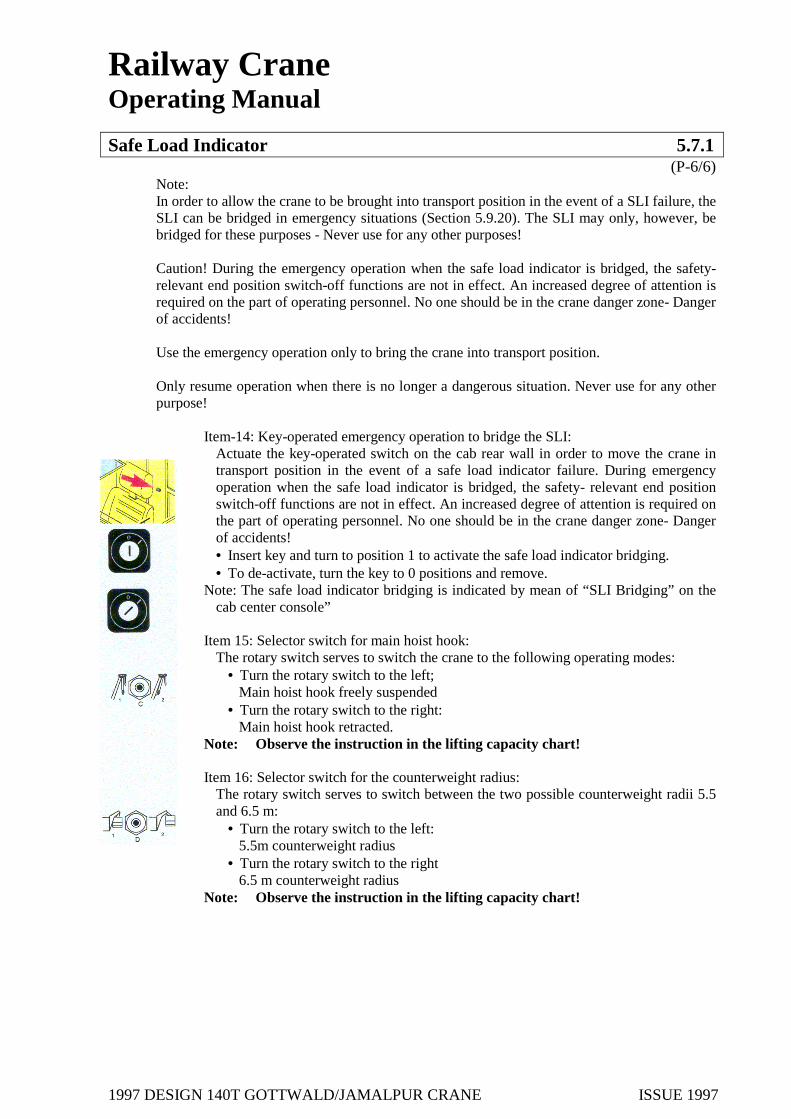
1997 DESIGN 140T GOTTWALD/JAMALPUR CRANE ISSUE 1997
Railway Crane Operating Manual
Safe Load Indicator 5.7.1 (P-6/6)
Note: In order to allow the crane to be brought into transport position in the event of a SLI failure, the SLI can be bridged in emergency situations (Section 5.9.20). The SLI may only, however, be bridged for these purposes - Never use for any other purposes! Caution! During the emergency operation when the safe load indicator is bridged, the safety-relevant end position switch-off functions are not in effect. An increased degree of attention is required on the part of operating personnel. No one should be in the crane danger zone- Danger of accidents! Use the emergency operation only to bring the crane into transport position. Only resume operation when there is no longer a dangerous situation. Never use for any other purpose!
Item-14: Key-operated emergency operation to bridge the SLI:
Actuate the key-operated switch on the cab rear wall in order to move the crane in transport position in the event of a safe load indicator failure. During emergency operation when the safe load indicator is bridged, the safety- relevant end position switch-off functions are not in effect. An increased degree of attention is required on the part of operating personnel. No one should be in the crane danger zone- Danger of accidents! • Insert key and turn to position 1 to activate the safe load indicator bridging. • To de-activate, turn the key to 0 positions and remove.
Note: The safe load indicator bridging is indicated by mean of “SLI Bridging” on the cab center console”
Item 15: Selector switch for main hoist hook: The rotary switch serves to switch the crane to the following operating modes:
• Turn the rotary switch to the left; Main hoist hook freely suspended • Turn the rotary switch to the right: Main hoist hook retracted.
Note: Observe the instruction in the lifting capacity chart! Item 16: Selector switch for the counterweight radius: The rotary switch serves to switch between the two possible counterweight radii 5.5
and 6.5 m: • Turn the rotary switch to the left: 5.5m counterweight radius • Turn the rotary switch to the right 6.5 m counterweight radius
Note: Observe the instruction in the lifting capacity chart!

1997 DESIGN 140T GOTTWALD/JAMALPUR CRANE ISSUE 1997
Railway Crane Operating Manual
Lighting 5.7.2 (P-1/2)
Description
The crane is fitted with sufficient lighting for crane and travel operations:
Safety Instructions
Crane operation is only permitted when there is adequate lighting. If visibility is considerably reduced in the event of lighting failure, operation must be stopped immediately.
Replace any faulty lighting equipment- Danger of accidents!
Operating Instructions:
The following is applicable to all buttons (item 12-19): To switch on the lighting: • Activate the buttons (items 12-19) once. To switch off the lighting: • Re-activate the buttons (items 12-19) Assignment of buttons
- Machinery house lighting - Cab lighting - Instrumental lighting - Boom head flood lights

1997 DESIGN 140T GOTTWALD/JAMALPUR CRANE ISSUE 1997
Railway Crane Operating Manual
Lighting 5.7.2 (P-2/2)
- Cab floodlights, left and right - Superstructure rope drum floodlights - Superstructure counterweight floodlights - Marker light
- -
- Diesel engine control panel lighting (see 5.4.1).
To switch on /off the diesel engine control panel: To switch on the lighting: • Turn the rotary switch downwards To switch off the lighting: • Turn the rotary switch upwards.

1997 DESIGN 140T GOTTWALD/JAMALPUR CRANE ISSUE 1997
Railway Crane Operating Manual
Signal Horns 5.7.3 (P-1/1)
Description The signal horns serve to provide and audible warning during crane and travel operations and generally in case of danger. The signal horns are installed at the front and rear on the superstructure. Each signal horn can be activated separately.
Safety Instructions
The signal horns serve to provide operating safety! Malfunctions must be reported immediately to the maintenance personnel. Operating Instructions To activate the signal horn at the front:
• Press button (3) as long as you desire the sound. To activate the signal horn at the rear:
• Press button (3) as long as you desire the sound. Note: As long as there are air pressure reserves, the signal horn function even when the ignition is switched off, i.e. when the crane is at standstill.

1997 DESIGN 140T GOTTWALD/JAMALPUR CRANE ISSUE 1997
Railway Crane Operating Manual
Screen Wiper / Wash System 5.7.4 (P-1/1)
Description
The electrically operated screen wiper and wash system serves to clean the front and roof screens. The front screen can be wiped and washed while the roof screen can only be wiped.
Safety Instructions The signal horns serve to provide operating safety! Malfunctions must be reported immediately to the maintenance personnel.
Operating Instructions:
Front Screen: To switch on/ off the front screen wiper: • The front screen wiper is switched on and off by pressing the wiper switch (4). To wash the front screen: • Activate the button (5) as long as required. Roof Screen: • The roof screen wiper is switched on and off by pressing the wiper switch (4).

1997 DESIGN 140T GOTTWALD/JAMALPUR CRANE ISSUE 1997
Railway Crane Operating Manual
Fans 5.7.5 (P-1/1)
Description: The fans serve to discharge the air from the cab interior. There are installed on the cab rear wall. Each fan can be switched on and off separately.
Safety Instructions The openings of the fans must not be blocked under any circumstances - Danger of short-circuiting and fire! Fan malfunctions must be reported to the maintenance ersonnel!
Operating Instructions: Fan 1: To switch on fan 1:
• Active button (1). To switch off fan 1.:
• Re-active button (1). Fan 2: To switch on fan 2:
• Active button (2). To switch off 2:
• Re-active switch (2)

1997 DESIGN 140T GOTTWALD/JAMALPUR CRANE ISSUE 1997
Railway Crane Operating Manual
Seat 5.7.6 (P-1/1)
Description
The seat installed is a comfortable seat with suspension and a number of adjusting possibilities.
Safety Instructions
For safety reasons, the individual control levers may only be released when the crane is stationary.
Caution! A proper seat serves to provide operating safety. Ensure that the seat can be properly adjusted. If the seat adjustment is faulty, stop crane operation immediately - Danger of accidents!
Operating Instructions Adjust the seat prior to commencing work to your personnel requirements. This will facilitate work and serve to provide operating safety. The seat can be adjusted as follows:
Item 1- Seat cushion inclination • The inclination of the seat cushion is infinitely variably adjustable by means of turning
the hand wheel clockwise or anti-clockwise. Item2- Seat height adjustment
• Infinitely variably adjustment to increase height- Turn handwheel clockwise; • Infinitely variably adjustment to decrease height- Turn handwheel anticlockwise. Adjust
the seat to your personal height and weight. Item 3 – Longitudinal adjustment
• Raise bar – shift the seat-release bar. Item 4 – Backrest inclination
• Backrest: Infinitely variably adjusted by means of a handwheel. • Headrest: Height can be infinitely variably adjusted. • Armrest: Infinitely variably adjusted by means of a handwheel; Can be completely
raised.

1997 DESIGN 140T GOTTWALD/JAMALPUR CRANE ISSUE 1997
Railway Crane Operating Manual
Parking Crane Safely 5.7.7 (P-1/1)
Description When the crane is not placed in train formation after completion of work, the crane must be parked safely.
Safety Instructions It is assumed that the ambient condition under which the crane is to be parked correspond to regulations. Operating Instructions The following requirements must be met to park the crane safely:
• Superstructure in longitudinal position • Boom in steepest working position • Boom without load • Outriggers must be propped and secured at least at the smallest propping base • Parking brake must be applied or brake shoes must be underpinned at the front and the rear • If required, leave on signal lights. • Suspension blocking applies / travel gear engaged • Ignition key must be removed and not on the crane • Closed and locked doors and windows • Closed protective housing • Remove both battery switches and store in safekeeping.
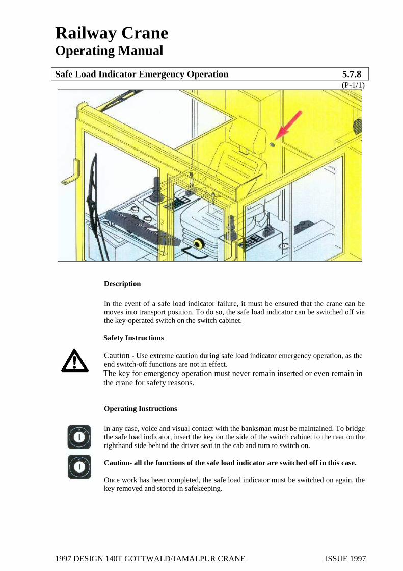
1997 DESIGN 140T GOTTWALD/JAMALPUR CRANE ISSUE 1997
Railway Crane Operating Manual
Safe Load Indicator Emergency Operation 5.7.8 (P-1/1)
Description
In the event of a safe load indicator failure, it must be ensured that the crane can be moves into transport position. To do so, the safe load indicator can be switched off via the key-operated switch on the switch cabinet.
Safety Instructions Caution - Use extreme caution during safe load indicator emergency operation, as the end switch-off functions are not in effect. The key for emergency operation must never remain inserted or even remain in the crane for safety reasons.
Operating Instructions
In any case, voice and visual contact with the banksman must be maintained. To bridge the safe load indicator, insert the key on the side of the switch cabinet to the rear on the righthand side behind the driver seat in the cab and turn to switch on. Caution- all the functions of the safe load indicator are switched off in this case. Once work has been completed, the safe load indicator must be switched on again, the key removed and stored in safekeeping.

1997 DESIGN 140T GOTTWALD/JAMALPUR CRANE ISSUE 1997
Railway Crane Operating Manual
Additional Equipment 5.7.9 (P-1/1)
Description The crane has extensive additional equipment such as electric sockets (24V), sun blinds and ash trays.
Safety Instructions
Any electrical unit malfunctions must be reported to the maintenance personnel for safety reasons. Caution – use only equipment in good order for the electrical sockets. Any electrical equipment must be unplugged from the sockets before travel operation begins – danger of accidents! Operating Instruction Electric sockets (24V) (Item 1):
The electrical sockets are splash-proof and are located in the cab as well as in both machinery houses. • Open the spring-loaded protective cap of the socket and plug in equipment which runs
on 24V direct current.
Sun blinds (Item 2): Sun blinds are mounted in the cab to provide protection against sun rays.

1997 DESIGN 140T GOTTWALD/JAMALPUR CRANE ISSUE 1997
Railway Crane Operating Manual
Recovery Winch 5.7.10 (P-1/2)
Description
By means of the recovery winch, objects can be recovered by derricking in. The winches, as well as the rope drum, gearbox and drive assembly are all located at the rear on the superstructure. The recovery winch rope is guided via a pulley guide from the rope exit on the front lefthand side below the cab, which is located on the superstructure to the winch.
Safety Instructions
Use caution when work is being carried out with the recovery winch-improper operation can cause serious injuries or properly damage - Danger of being crushed, bumped or drawn into the equipment! Loads not attached or pulled properly can cause serious accidents - Danger of accidents! Mortal danger! The tension figure indicated in the Technical Data for the recovery winch must not be exceeded under any circumstances. The maximum wire rope loading must not be exceeded under any circumstances. The recovery winch is not suitable for equipment used to convey or lift persons. Replace any damaged winch parts without fail before using!
The wire rope must be guided over all rope pulleys according to regulations. Caution, prior to beginning travel, the rope of the recovery winch must be completed coiled and no objects should be attached - Danger of Accidents!
The recovery winch can be used when the crane is free-on-wheels or propped- Caution- Never operate any crane or travel functions when the recovery winch is in use- Danger of accidents! Caution- When the winch is operated and the crane is free-on-wheels, underpin the wheels with drag shoes.
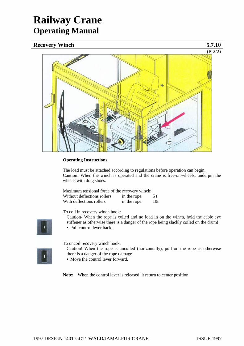
1997 DESIGN 140T GOTTWALD/JAMALPUR CRANE ISSUE 1997
Railway Crane Operating Manual
Recovery Winch 5.7.10 (P-2/2)
Operating Instructions The load must be attached according to regulations before operation can begin. Caution! When the winch is operated and the crane is free-on-wheels, underpin the wheels with drag shoes. Maximum tensional force of the recovery winch: Without deflections rollers in the rope: 5 t With deflections rollers in the rope: 10t To coil in recovery winch hook:
Caution- When the rope is coiled and no load in on the winch, hold the cable eye stiffener as otherwise there is a danger of the rope being slackly coiled on the drum! • Pull control lever back.
To uncoil recovery winch hook:
Caution! When the rope is uncoiled (horizontally), pull on the rope as otherwise there is a danger of the rope damage! • Move the control lever forward.
Note: When the control lever is released, it return to center position.

1997 DESIGN 140T GOTTWALD/JAMALPUR CRANE ISSUE 1997
Railway Crane Operating Manual
Operation Diagrams 6. (P-1/1)
Control Stand Diagram General Crane Diagram

1997 DESIGN 140T GOTTWALD/JAMALPUR CRANE ISSUE 1997
Railway Crane Operating Manual
Operation Diagram 6.1 (P-1/1)

1997 DESIGN 140T GOTTWALD/JAMALPUR CRANE ISSUE 1997
Railway Crane Operating Manual
Operation Diagram 6.2 (P-1/1)

1997 DESIGN 140T GOTTWALD/JAMALPUR CRANE ISSUE 1997
Railway Crane Operating Manual
Sub-Supplier Documentation 7 (P-1/1)
1. Recovery winch Type: GFT 36 W3 2021 2. Derricking gear: type: GFT W3 8228, German 3. Hoist 1: Type: GFT W3 8228, German 4. Hoist 2: Type: GFT 26 W2 8022, German 5. Slewing gear: Type: GFB 80 T3 1008, German 6. SAB brake unit, mode PBACF servicing regulations 7. SAB brake unit, model PBAC servicing regulations 8. Gutehoffnungshutte Radsatz GmbH / Drive and running wheel sets 9. BSI - wheel brake disk manual R780G 10. BSI - brake cylinder expander unit manual 11. PAT- safe load indicator / Operating Manual IK350/1327 12. Wabco, Instruction Recommendations and Maintenance Instructions for the
compressors 13. Kirloskar Oil Engines limited Type: HA 294 14. Cummins Diesel Engine 15. Pump distributor gearbox GFC 230 1048