Embed Size (px)
Citation preview

8/12/2019 Operating Microscopes in Endodontics
http://slidepdf.com/reader/full/operating-microscopes-in-endodontics 1/42
The Use of the Operating Microscope inEndodontics
Gary B. Carr and Arnaldo Castellucci
INTRODUCTION
Endodontists have frequently boasted they can do muchof their work blindfolded simply because there is “nothingto see.” The truth of the matter is that there is a great deal
to see if only we had the right tools.1
In the last fifteen years for both non-surgical and surgicalendodontics, there has been an explosion of newtechnologies, new instruments and new materials. Thesedevelopments have improved the precision with whichendodontics can be performed. These advances haveenabled clinicians to complete procedures which were onceconsidered impossible or which could be performed onlyby extremely talented or lucky clinicians. The mostimportant revolution has been the introduction and thenthe widespread adoption of the operating microscope.
Operating microscopes have been used for decades inmany other medical disciplines: ophthalmology,neurosurgery, reconstructive surgery, otorhinolaryngology,and vascular surgery. Its introduction into dentistry in the
last fifteen years, particularly in endodontics, hasrevolutionized how endodontics is practiced worldwide.
Until recently, endodontic therapy was performed usingour tactile sensitivity, and the only way to “see” inside theroot canal system was to take a radiograph. To performendodontic therapy entailed “working blind,” in that mostof the effort was done using only tactile skills with aminimum of visual information available. Before theintroduction of the operating microscope we could “feel”the presence of a problem (a ledge, a perforation, ablockage, a broken instrument), and the clinicalmanagement of that problem was never predictable anddepended on happenstance. Most endodontic procedures
occurred in a visual void which placed a premium on thedoctor’s tactile dexterity, mental imaging and perseverance.
The introduction of the operating microscope haschanged both non-surgical and surgical endodontics. Innon-surgical endodontics, every challenge existing in thestraight portion of the root canal system, even if located inthe most apical part, can be easily seen and managedcompetently under the microscope. In surgical endodontics,it is possible to carefully examine the apical segment of theroot-end and perform an apical resection of the root
without an exaggerated bevel, thereby making Class I cavitypreparations along the longitudinal axis of the root easy toperform.
The purpose of this chapter is to provide the basicinformation of how an operating microscope is used in a
clinical endodontic practice and to give an overview of itsclinical and surgical applications.
ON THE RELATIVE SIZES OF THINGS
It is difficult, even for a scientist, to have an intuitiveunderstanding of size. Specifically, a dentist must have anaccurate understanding of the relationship between thegross dimensions involved in restorative procedures and the
dimensions of those deleterious elements that causerestoration failure: bacteria, open margins, imperfection inrestorative materials, etc. In other words, a filling or acrown may appear to be well placed, but if bacteria can

8/12/2019 Operating Microscopes in Endodontics
http://slidepdf.com/reader/full/operating-microscopes-in-endodontics 2/42
A
leak through the junction between tooth and restorativematerial, then treatment is compromised.
A brief review of relative size may be helpful. Cells aremeasured in microns (millionths of a meter) and a singlebacterial cell is about one micron in diameter. One cubicinch of bacteria can hold about a billion cells. A typicalhuman (eukaryotic) cell is 25 microns in diameter so that anaverage cell can hold more than 10,000 bacteria. Bycomparison, viruses are so small that thousands can fit
within a single bacterial cell. Simple calculations show thatone cubic inch can contain millions of billions of viruses.
Unfortunately, the calculations do not end there. Forexample, macromolecules (e.g., bacterial toxins, etc.) aremeasured in nanometers, or one billionth of a meter (Fig.32.1). Some of these bacterial toxins are so potent that evennanograin quantities can cause serious complications andeven death. Clearly, dentists are at a severe disadvantage intheir attempts to replace natural tooth structure withartificial materials that do not leak, in view of the virtually
invisible microbiologic threats to restoration integrity.5
THE LIMITS OF HUMAN VISION
Webster defines resolution as the ability of an opticalsystem to make clear and distinguishable two separateentities. Although clinicians have routinely strived to createbacterial-free seals, the resolving power of the unaidedhuman eye is only .2 mm. In other words, most people who
view two points closer than .2 mm will see only one point.For example, Figure 32.2 shows an image of a dollar bill.
The lines making up George Washington’s face are .2mmapart. If one holds the bill close enough, one can probablyjust barely
B
make out the separation between these lines. In fact, if they were any closer together, you would not be able to discern

8/12/2019 Operating Microscopes in Endodontics
http://slidepdf.com/reader/full/operating-microscopes-in-endodontics 3/42
that they were separate lines. The square boxes behind Washington’s head are .1 mm apart and are not discernable
as separate boxes by most people. They are beyond theresolving power of the unaided human eye. For comparisonsake, it would take about 100 bacteria to span that square.Clinically, most dental practitioners will not be able to seean open margin smaller than .2 mm. The film thickness ofmost crown and bridge cements is 25 microns (.025 mm),or well beyond the resolving power of the naked eye.
Optical aids (loupes, microscopes, surgical headlamps,fiber optic handpiece lights, etc.) can improve resolution bymany orders of magnitude. For example, a commonoperating microscope can raise the resolving limit from .2mm to .006 mm (6 microns), a dramatic improvement.Figure 32.3 shows the improvement in resolution obtainedby the standard operating microscope used in dentistrytoday. At the highest power, a margin open only .006 mm isessentially sealed and even beyond the common cementthickness used in restorative dentistry. Table I summarizesthe relationship between object size and resolving power.
Table I
2.7x 4.1x 6.8x 10.9x 17x 80.9mm 53.9mm 32.4mm 0.2mm12.9mm
WHY ENHANCED VISION IS NECESSARY IN
DENTISTRY
It should be obvious from the previous discussion thatany device that enhances or improves a clinician’s resolvingpower is extremely beneficial in producing precision

8/12/2019 Operating Microscopes in Endodontics
http://slidepdf.com/reader/full/operating-microscopes-in-endodontics 4/42
dentistry. Restorative dentists, periodontists, andendodontists routinely perform procedures requiring
resolution well beyond the .2 mm limit of human sight.Crown margins, scaling procedures, incisions, root canal
location, caries removal, furcation and perforation repair,post placement or removal, and bone-and soft-tissue
grafting procedures are only a few of the procedures thatdemand tolerances well beyond the .2 mm limit.
OPTICAL PRINCIPLES
Since all clinicians must “construct” three-dimensionalstructures in a patient’s mouth, stereopsis, or three-dimensional perception, is critical to achieving precisiondentistry. Dentists appreciate that human mouth is arelatively small space in which to operate, especiallyconsidering the size of the available instruments ( burs,handpieces, etc.) and the comparatively large size of theoperator’s hands. Attempts have been made to use themagnifying endoscopes used in artroscopic procedures but
these devices require viewing on a two-dimensionalmonitor and the limitations of working in 2D space are toorestrictive to be useful.
Several elements are important for consideration inimproving clinical visualization. Included are factors suchas:
stereopsismagnification rangedepth of fieldresolving power
working distancespherical and chromatic distortion (i.e., aberration)ergonomicseyestrainhead and neck fatiguecost.
Dentists can increase their resolving ability without usingany supplemental device by simply moving closer to theobject of observation. This can be accomplished indentistry by raising the patient up in the dental chair tobe closer to the operator or by the operator bendingdown to be closer to the patient.
25
This method is limited,however, by the eye’s ability to refocus at the diminisheddistance.
Most people cannot refocus at distances closer than 10-12 cm. Furthermore, as the eye-subject distance (i.e., focallength) decreases, the eyes must converge, creatingeyestrain. One must also take into consideration the factthat as one ages the ability to focus at closer distances iscompromised. This phenomenon is called presbyopia and isdue to the fact that the lens of the eye loses flexibility with
age. The eye (lens) is unable to accommodate and produceclear images of near objects. The nearest point at which theeye can focus accurately, exceeds ideal working distance.25
As the focal distance decreases, depth of field decreasesas well. When one considers the problem of theuncomfortable proximity of the practitioner’s face to thepatient, moving closer to the patient is not a satisfactorysolution for increasing a clinician’s resolution.
Alternatively, image size and resolving power can be
increased with magnification, by magnifying the imagethrough lenses with no need for the position of the objector the operator to change.
LOUPES
Magnifying loupes were developed to address theproblem of proximity, decreased depth of field, andeyestrain occasioned by moving closer to the subject.
Loupes are classified by the optical method in which theyproduce magnification. There are three types of binocularmagnifying loupes: (1) a diopter, flat-plane, single-lensloupe, (2) a surgical telescope with a Galileian system
configuration (two lens system), (3) a surgical telescope with a Keplarian system configuration (prism roof designthat folds the path of light).
The diopter system relies on a simple magnifying lens. The degree of magnification is usually measured in diopters.One diopter (D) means that a ray of light that would befocused at infinity now would be focused at 1 meter (100cm or 40 inches). A lens with 2 D
∗ Depth of field refers to the ability of the lens system to focus on
objects that are both near and far without having to change the loupeposition. As magnification increases, depth of field decreases. Also, thesmaller the field of view, the shallower the depth of field. Depth of fieldis approximately 5 inches (12.5 cm) for a 2x loupe, 2 inches (6 cm) for a3.25x loupe, and 1 inch (2.5 cm) for a 4.5x loupe.
designation would focus to 50 cm (19 inches); a 5 D lens
would focus to 20 cm (8 inches). Confusion occurs when adiopter single-lens magnifying system is described as 5 D.

8/12/2019 Operating Microscopes in Endodontics
http://slidepdf.com/reader/full/operating-microscopes-in-endodontics 5/42
This does not mean 5x power (5 times the image size).Rather, the 5 D designation signifies that the focusing
distance of the eye to the object is 20 cm (less than 8inches) with an increased image size of approximately 2x (2times actual size).
“
The only advantage of the diopter systemis that is the most inexpensive system, but it is also the lessdesirable because the plastic lenses that uses are not alwaysoptically correct. Furthermore, the increased image sizedepends on being closer to the viewed object, and this cancompromise posture and create stresses and abnormalitiesin the musculoskeletal system. 25
The surgical telescope of either Galileian or Keplariandesign produce an enlarged viewing image with a multiple-lens system positioned at a working distance between 11and 20 inches (28-51 cm). The most used and suggested
working distance is between
11 and 15 inches (28-38 cm).
The Galileian system provides a magnification rangefrom 2x up to 4.5x and is a small, light and very compactsystem (Fig. 32.4).
The prism loupes (Keplarian system) use refractiveprisms and they are actually telescopes with complicatedlight paths, which provide magnifications up to 6x (Fig.32.5).
Both systems produce superior magnification, correctspherical and chromatic aberrations, have excellent depthof field, and are capable of increased focal length (30-45cm), thereby reducing both eyestrain and head and neckfatigue. Both these types of loupes offer significantadvantages over simple magnification eyeglasses.
The disadvantage of loupes is that the practicalmaximum magnification is only about 4.5 diameters.Loupes are available with higher magnification, but they areheavy and unwieldy with limited field of view. Usingcomputerized techniques, some manufacturers can provide
magnifications from 2.5x to 6x with an expanded field.Nevertheless, such loupes require a constrained physicalposture and cannot be worn for long periods of time
without producing significant head, neck, and back strain.
THE PROBLEM OF LIGHT
By increasing light levels, one can increase apparentresolution (the ability to distinguish two object close toeach other as separate and distinct). Light intensity isdetermined by the inverse square law, which states that theamount of light received from a source is inverselyproportional to the square of the distance. For example, ifthe distance of the light to the subject is decreased by half,the amount of light at the subject increases four times.
Based on the law, therefore, most standard dental operatorylights are too far away to provide the adequate light levelsrequired for many dental procedures.
8/12/2019 Operating Microscopes in Endodontics
http://slidepdf.com/reader/full/operating-microscopes-in-endodontics 6/42
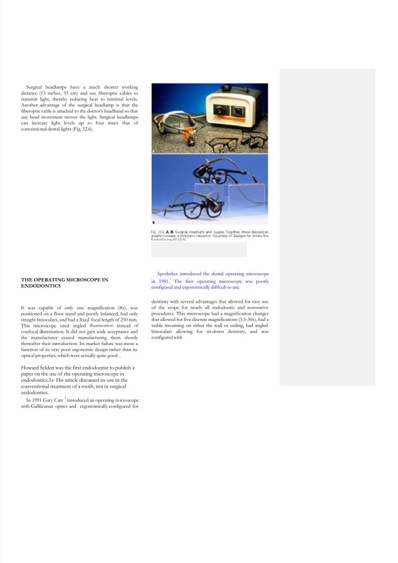
Surgical headlamps have a much shorter workingdistance (13 inches, 35 cm) and use fiberoptic cables to
transmit light, thereby reducing heat to minimal levels. Another advantage of the surgical headlamp is that thefiberoptic cable is attached to the doctor’s headband so thatany head movement moves the light. Surgical headlampscan increase light levels up to four times that ofconventional dental lights (Fig. 32.6).
THE OPERATING MICROSCOPE IN
ENDODONTICS
Apotheker introduced the dental operating microscope
in 1981.1
The first operating microscope was poorlyconfigured and ergonomically difficult to use.
It was capable of only one magnification (8x), waspositioned on a floor stand and poorly balanced, had onlystraight binoculars, and had a fixed focal length of 250 mm.
This microscope used angled illumination instead ofconfocal illumination. It did not gain wide acceptance andthe manufacturer ceased manufacturing them shortlythereafter their introduction. Its market failure was more afunction of its very poor ergonomic design rather than itsoptical properties, which were actually quite good. .
Howard Selden was the first endodontist to publish apaper on the use of the operating microscope inendodontics.1a His article discussed its use in theconventional treatment of a tooth, not in surgical
endodontics.In 1991 Gary Carr
3introduced an operating microscope
with Gallileanan optics and ergonomically configured for
dentistry with several advantages that allowed for easy useof the scope for nearly all endodontic and restorativeprocedures. This microscope had a magnification changerthat allowed for five discrete magnifications (3.5-30x), had astable mounting on either the wall or ceiling, had angledbinoculars allowing for sit-down dentistry, and wasconfigured with

8/12/2019 Operating Microscopes in Endodontics
http://slidepdf.com/reader/full/operating-microscopes-in-endodontics 7/42
adapters for an assistant’s scope and video/35 mm cameras
(Fig. 32.7). It utilized a confocal illumination module sothat the light path was in the same optical path as the visualpath and this gave far superior illumination than the angledlight path of the earlier scope. This microscope gained rapidacceptance within the endodontic community, and now isthe instrument of choice not only for endodontics but forperiodontics and restorative dentistry as well. The opticalprinciples of the dental microscope are seen in Figure 32.8.
The efficient use of the microscope requires advancedtraining. Many endodontic procedures are performed at 10-15x and some requires magnifications as high as 30x.Operating comfortably at these magnifications requiresaccommodation to new skills that until recently were nottaught in dental schools. Among other things, working atthese higher-power magnifications brings the clinician intothe realm where even slight hand movements are disruptive
and physiologic hand tremor can be a problem.In 1995 the American Association of Endodontists
formally recommended to the Commission on Dental Accreditation (CODA) of the American Dental Associationthat microscopy training be included in the new
Accreditation Standards for Advanced Specialty EducationProg rams in Endodontics. At the Commission’s January1996 meeting, the proposal was agreed upon, and in
January 1997 the new standards, making microscopytraining mandatory, became effective.20
Efficient use of an operating microscope inendodontics
Although the operating microscope is now recognized as apowerful adjunct in endodontics, it has not been adopteduniversally by all endodontists.. It is seen by manyendodontists as simply “another tool” and not as “a way ofpractice” that defines how an endodontist works. Althoughcost is frequently cited as the major impediment, in truth, itis not cost, but a failure to understand and implement thepositional and ergonomic skills necessary to effectively usea microscope that has restricted its universal use on allendodontic cases.
The occasional or intermittent use of a microscope on acase results in the very inefficient use of a clinician’s time and represents a disruption in the treatment flow of a case
that can only negatively affect the final result. Clinicians who practice this way seldom realize the full advantage of amicroscopic approach and never develop the visual andergonomic skills necessary to operate at the highest level.
The skillful use of an operating microscope entails its use forthe entire procedure from start to finish. Working in such a
way depends upon refinement of ergonomic and visualskills to a very high level.
Comment [DC1]: MigrationConfirmed set by D
Carr

8/12/2019 Operating Microscopes in Endodontics
http://slidepdf.com/reader/full/operating-microscopes-in-endodontics 8/42
THE ANATOMY OF THEOPERATING MICROSCOPE
The operating microscope consists of three primarycomponents: the supporting structure, the body of themicroscope, and the light source.
The supporting structure
It is essential that the microscope be stable while inoperation, yet remain maneuverable with ease andprecision, particularly when used at high power.
12
Thesupporting structure can be mounted on the floor, ceiling,or wall (Fig. 32.9). As the distance between the fixationpoint and the body of the microscope is decreased, thestability of the set up is increased. In clinical settings withhigh ceilings or distant walls, the floor mount is preferable.
Although it is stated that it can be easily moved from oneoperatory room to another, in fact, it is very cumbersometo do this and is a very ineffective way to use a microscope.
Fig. 32.9. A. Global ProtegeTM
Floorstand model. Compact H-base withlarge locking casters occupies minimal floor space. B. Global Protege
TM
Wallmount model. The extension arm and oblique coupler allow greatermaneuverability. C. Global Protege
TM
Ceiling mount model. The ceilingmount is designed to permit maximum range of operation while totallyeliminating the use of floor space, and when not in use it folds into a
convenient storage position (Courtesy of Global Surgical
TM
Corporation,St. Louis, MO, USA).
Far preferable is the wall mount or, even better, the ceilingmount. Careful attention should be given to the precisesetting of the arms. The built-in springs should be tightenedaccording to the weight of the body of the microscope toestablish perfect balance in any position. This permitsprecise visualization and renders the fine focus unnecessaryin the majority of c linical circumstances. 12
The body of the microscope
The body of the microscope is the most importantcomponent of the instrument (Fig. 32.10), and it containsthe lenses and prisms responsible of magnification andstereopsis. The body of the microscope is made of
eyepieces, binoculars, magnification changer factor, and theobjective lens.

8/12/2019 Operating Microscopes in Endodontics
http://slidepdf.com/reader/full/operating-microscopes-in-endodontics 9/42
Eyepieces are generally available in powers of 10x, 12.5x,
16x, and 20x. The most commonly used are 10x and 12.5x. The end of each eyepiece has a rubber cup that can beturned down for clinicians who wear eyeglasses. Eyepiecesalso have adjustable diopter settings. Diopter settings rangefrom -5 to +5 and are used to adjust for accommodation,
which is the ability to focus the lens of the eyes. Diopter
setting is particularly important when an assistant scope anddocumentation equipment are used, so that everything is
uniformly in focus (par focalled). It is suggested to checkthe diopter settings frequently. If documentationaccessories are used, the eyepiece which is on the same sideof the accessory should be provided with a “reticule” that
will help to keep the images well centered in the field. The binoculars contain the eyepieces and allow the
adjustment of the interpupillary distance. Their focal lengthis 125 or 160 mm. They are aligned manually or with asmall knob until the two divergent circles of light combineto effect a single focus. Once the diopter setting andinterpupillary distance adjustments have been made, theyshould not have to be changed until the microscope is usedby a surgeon with different optical requirements. 19
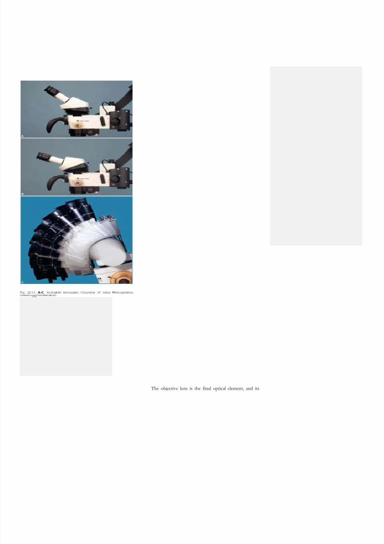
Binoculars are
available with straight, inclined, or inclinable tubes. Straighttube binoculars are orientated so that the tubes are parallelto the head of the microscope. They are generally used inotology and are not well suited for dentistry. Inclined tubesare fixed at a 45° angle to the line of sight of themicroscope (Fig. 32.11). The inclinable tubes are adjustable(Fig. 32.12) through a range of angles and allow theclinician to always establish a very comfortable workingposition. It is therefore obvious that, even if moreexpensive, the inclinable binocular is always to be preferred.
Magnification changers are available as 3-, 5-, or 6-stepmanual changers, or a power-zoom changer. They arelocated within the head of the microscope. Manual step
changers consist of lenses that are mounted on a turret thatis connected to a dial located on the side of the microscope.
The magnification is altered by rotating the dial. A powerzoom changer is a series of lenses that move back and forthon a focusing ring to give a wide range of magnificationfactors. Focusing with a power zoom microscope isperformed by a foot control or by a manual overridecontrol knob located on the head of the microscope. Theadvantage of the power zoom changers is that they avoid
the momentary visual disruption or jump that occurs withmanual step changers as the clinician rotates the turret andprogresses up or down in magnification. The disadvantagesare the following: the excursion from the minimum to themaximum magnification is quite slow, while it is must faster
with the manual step changers; the number of lenses ismuch higher compared to the manual step changers, andthis means a greater absorption of light; power zoomchanger are much more expensive.
8/12/2019 Operating Microscopes in Endodontics
http://slidepdf.com/reader/full/operating-microscopes-in-endodontics 10/42
The objective lens is the final optical element, and its
8/12/2019 Operating Microscopes in Endodontics
http://slidepdf.com/reader/full/operating-microscopes-in-endodontics 11/42
focal length determines the working distance between themicroscope and the surgical field. The range of focal length
varies from 100 mm to 400 mm. A 200 mm focal lengthallows approximately 20 cm (8 inches) of working distance,
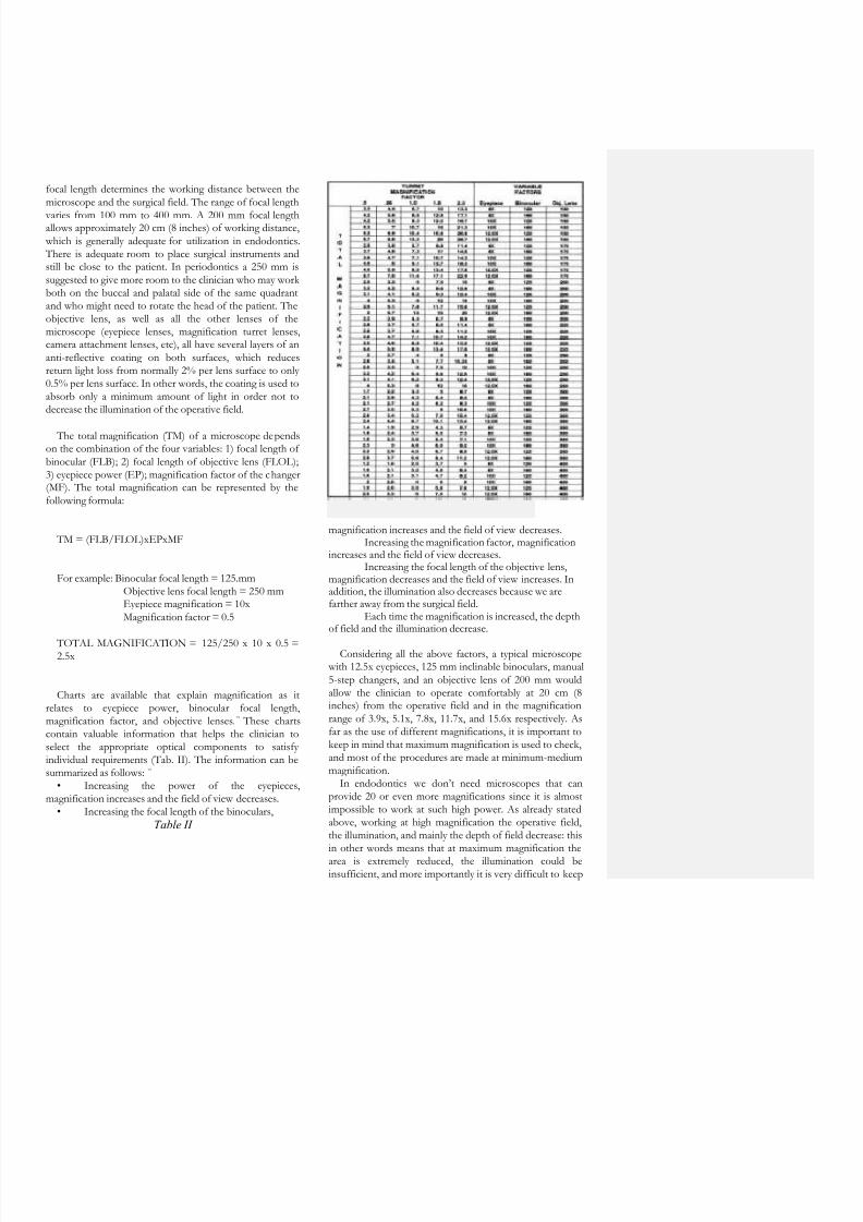
which is generally adequate for utilization in endodontics. There is adequate room to place surgical instruments andstill be close to the patient. In periodontics a 250 mm issuggested to give more room to the clinician who may workboth on the buccal and palatal side of the same quadrantand who might need to rotate the head of the patient. Theobjective lens, as well as all the other lenses of themicroscope (eyepiece lenses, magnification turret lenses,camera attachment lenses, etc), all have several layers of ananti-reflective coating on both surfaces, which reducesreturn light loss from normally 2% per lens surface to only0.5% per lens surface. In other words, the coating is used toabsorb only a minimum amount of light in order not todecrease the illumination of the operative field.
The total magnification (TM) of a microscope dependson the combination of the four variables: 1) focal length ofbinocular (FLB); 2) focal length of objective lens (FLOL);3) eyepiece power (EP); magnification factor of the changer(MF). The total magnification can be represented by thefollowing formula:
TM = (FLB/FLOL)xEPxMF
For example: Binocular focal length = 125.mmObjective lens focal length = 250 mmEyepiece magnification = 10xMagnification factor = 0.5
TOTAL MAGNIFICATION = 125/250 x 10 x 0.5 =2.5x
Charts are available that explain magnification as itrelates to eyepiece power, binocular focal length,magnification factor, and objective lenses.
19
These chartscontain valuable information that helps the clinician toselect the appropriate optical components to satisfyindividual requirements (Tab. II). The information can besummarized as follows: 19
• Increasing the power of the eyepieces,magnification increases and the field of view decreases.
• Increasing the focal length of the binoculars,
Table II
magnification increases and the field of view decreases.Increasing the magnification factor, magnification
increases and the field of view decreases.Increasing the focal length of the objective lens,
magnification decreases and the field of view increases. Inaddition, the illumination also decreases because we arefarther away from the surgical field.
Each time the magnification is increased, the depthof field and the illumination decrease.
Considering all the above factors, a typical microscope with 12.5x eyepieces, 125 mm inclinable binoculars, manual5-step changers, and an objective lens of 200 mm wouldallow the clinician to operate comfortably at 20 cm (8inches) from the operative field and in the magnificationrange of 3.9x, 5.1x, 7.8x, 11.7x, and 15.6x respectively. Asfar as the use of different magnifications, it is important tokeep in mind that maximum magnification is used to check,and most of the procedures are made at minimum-mediummagnification.
In endodontics we don’t need microscopes that canprovide 20 or even more magnifications since it is almostimpossible to work at such high power. As already statedabove, working at high magnification the operative field,the illumination, and mainly the depth of field decrease: thisin other words means that at maximum magnification the
area is extremely reduced, the illumination could beinsufficient, and more importantly it is very difficult to keep

8/12/2019 Operating Microscopes in Endodontics
http://slidepdf.com/reader/full/operating-microscopes-in-endodontics 12/42
the operative field constantly in focus. A little movement ofthe patient or sometimes just his/her breathing can be
enough to be completely out of focus.
The fine focus can be done manually using the deviceintegrated in the objective lens, or rotating a fine focusknob, which raises the entire body of the microscope, or byan electric foot control.
One might think that working constantly with themicroscope will cause eyestrain and eye fatigue. Not only isthis not true, but what is true is just the opposite. As a
matter of fact, operating microscopes possess the additionalbenefit of Galileian Optics, as they focus at infinity andsend parallel beams of light to each eye.
12,19
With parallellight, the operator’s eyes are at rest, as though looking offinto the distance, permitting performance of time-consuming procedures without inducing eye fatigue, like wehave if we are working with the naked eye at a smalldistance from the patient requiring convergent optics.
The light source
The light source is one of the most important features ofan operating microscope.12 Besides optics, the light source is
responsible for operating in operative fields that are smalland deep like the root canal. This is possible because themicroscope provides a powerful coaxial illumination, whichmeans that the light is coaxial with the line of sight andeliminates the presence of any shadows.
Some microscopes provide a double beam of light, sothat the operative field gets the light from two differentangles. This type of illumination is to be avoided; eventhough the illumination is apparently double, in realityneither of the two beams of light is coaxial. Therefore it willbe impossible to have enough light inside the root canal.
Two light source systems are commonly available:halogen light and xenon light. The halogen light frequentlydoes not provide enough illumination for qualitydocumentation especially at higher powers. The xenonlight is much more powerful and provides a brighter light atabout 5,000° Kelvin approximating day light. In both casesthe light intensity is controlled by a rheostat and cooled bya fan. After the light reaches the surgical field, it is reflectedback through the objective lens, through the magnificationchanger lenses, and through the binoculars and then exitsto the eyes as two separate beams of light. The separationof the light beams is what produces the stereoscopic effectthat allows the clinician to see depth of field.19
Some microscopes are able to focus the light to a smallerdiameter. At minimum magnification, the illuminated areais about 6 cm in diameter. The same area is illuminated
when we work at medium or maximum magnification, while the area of the operative field is much smaller maybeless than 1 cm. To avoid this and to concentrate the light
where it is really useful, some manufacturer produce a
condenser which not only reduces the illumination field size(like any diaphragm can do), but mainly condenses to asmall spot the same amount of light that at smallmagnification is illuminating a bigger area (Fig. 32.13).
Accessories
Some microscopes are built with fixed components and
don’t allow the insertion any accessories. Some others canbe personalized with accessories like the assistant scope and

8/12/2019 Operating Microscopes in Endodontics
http://slidepdf.com/reader/full/operating-microscopes-in-endodontics 13/42
documentation tools, like a 35-mm and a video camera. Tosupply light to such accessories, a beam splitter must be
inserted in the pathway of light as it returns to theoperator’s eyes between the binoculars and themagnification changer. The beam splitter divides each pathof light into two parts (50:50); one goes to the operator eyeand the other goes to the accessory (Fig. 32.14). Usually,half of the light of the left beam goes to the assistant scope,half of the light of
the right beam goes to the documentation accessories. Inother words, this means that our dental assistant will see
what we see with our left eye, and we will document what we see with our right eye. Furthermore, even though thedental assistant has her binoculars, she cannot have a
stereoscopic view because she will see with two eyes the visual field from just the left port of the beam splitter.
Global Surgical Corporation makes a “VirtualBeamsplitter”, which splits the light in a ratio of 95% to 5%instead of the traditional 50/50 (Fig. 32.15). The split isdone by having a totally reflective coating across a smallarea of the beam splitter, while the remaining area of thebeam splitter is completely transmissive. This implies thatthe primary surgeon receives 100% of the light across thelarge area of the beam splitter, and the camera receives100% of the light across the
A
B
small area of the beam splitter. In practice, the amount oflight received by the virtual beam splitter is enough for theassistant scope or for the videocamera, but it is not enoughfor the 35 mm camera.
The accessories for documentation are the video cameraand the 35 mm camera. They can be mounted separately orcombined, through specifically designed photo or videoadaptors connected to the beam splitter. In case one wantsto use both, it is important to keep in mind that the 50% oflight that goes to the documentation accessories will be onemore time divided in two parts, one for the video cameraand one for the 35 mm camera. Designs for Vision(Ronkonkoma, NY) makes a particular adaptor which,instead of mounting a prism that divides the light into twoparts, has a mirror which deviates all the light either to the
video or to the photographic documentation. With thisadaptor, there is no loss of light. The only disadvantage isthat it is impossible to take pictures while the video isrecording.
While the light provided by the light source of themicroscope is enough for video documentation of good
quality, it is not enough for the 35 mm camera to take goodpictures. For this reason, it is usually necessary tosupplement the microscope’s lighting system by adding a

8/12/2019 Operating Microscopes in Endodontics
http://slidepdf.com/reader/full/operating-microscopes-in-endodontics 14/42
strobe over the objective lens. Several strobes arecommercially available and can be adapted to the operating
microscope (Fig. 32.16). The digital camera can also
download the images directly into a computer, allowing therapid organization of a rich database of images.
The video camera can be connected to a monitor, a videotape recorder, and a video printer. The monitor can beused not only to motivate the patient, who can see theentire videotaped procedure, but mainly to the secondsurgical assistant, who can follow the surgical procedureand give to the operator the right instruments at the rightmoment. Looking at the monitor, the dental assistant canalso work as a video director, and pause the recording if heor she thinks the picture is off center or out of focus.
Photo and cine adaptors are available with different focallength, so that the clinician can choose the one that willallow the recording of an image with the samemagnification and field of view as seen through themicroscope.
Other important accessories are the eyepiece with thereticle and the assistant scope.
An eyepiece with a reticle field can be substituted for aconventional eyepiece and can prove an invaluable aid foralignment during videotaping and 35 mm photography.
19
Very useful is the assistant scope (Fig. 32.17), whichallows the assistant to “assist” the operator during theentire procedure. Particularly during surgical endodontics,the dental assistant can do
A
B
C

8/12/2019 Operating Microscopes in Endodontics
http://slidepdf.com/reader/full/operating-microscopes-in-endodontics 15/42
her job much more precisely looking through the assistantscope, compared to just looking at the monitor. The second
assistant of surgical endodontics will follow the procedurethrough the monitor, while the first assistant is controllingthe bleeding with the suction tips using the auxiliaryarticulating binocular (Fig. 32.18).
The Laws of Ergonomics
An understanding of efficient work flow using amicroscope entails a knowledge of the basics of ergonomic
motion. Ergonomic motion is divided up into five(5)classes of motion:
1. ClassI Motion: moving only the fingers
2. Class II Motion: Moving only the fingers and wrists
3. Class III Motion: Movement originating from theelbow
4. Class IV Motion: Movement originating from theshoulder
5. Class V Motion: Movement that involve twisting orbending at the waist

8/12/2019 Operating Microscopes in Endodontics
http://slidepdf.com/reader/full/operating-microscopes-in-endodontics 16/42
Positioning the microscope
The introduction of the operating microscope in a dentaloffice requires significant forethought , planning, and anunderstanding of the required ergonomic skills necessary touse the microscope efficiently. Proper positioning, for theclinician, patient, and assistant is absolutely necessary. Mostproblems in using a microscope in a clinical setting arerelated either to positioning errors or lack of ergonomicskills on the part of the clinician. . It is possible to work atthe microscope in complete comfort with little or nomuscle tension if proper ergonomic guidelines are followed.
In chronological order, the preparation of themicroscope involves the following maneuvers:1 Operator positioning2 Rough positioning of the patient3 Positioning of the microscope and focusing4 Adjustment of the interpupillary distance5 Fine positioning of the patient6 Parfocal adjustment7 Fine focus adjustment8 Assistant scope adjustment
1) operator positioninG
The correct operator position for nearly all endodonticprocedures is directly behind the patient at the 11 or12 O’clock position. Positions other than the 11 or 12o’clock position (for example 9 o’clock) may seemmore comfortable when first learning to use amicroscope, but as greater skills are acquired, changingto other positions rarely serves any purpose. Clinicians
who are constantly changing their positions around thescope are extremely inefficient in their procedures.
The operator should adjust the seating position so thatthe hips are 90 degrees to the floor, the knees are 90degrees to the hips and the forearms are 90 degrees to theupper arms. 14 The operator forearms should lie comfortablyon the armrest of the operator’s chair and his or her feetshould be placed flat on the floor (Fig. 32.19). The backshould be in a neutral position, erect, perpendicular to thefloor, with the natural lordosis of the back being supportedby the lumbar support of the chair, with the eyepiece
inclined so that the head and neck can be held at an anglethat can be comfortably be sustained. This position is
maintained regardless of the arch or quadrant being workedon. It is the patient who is moved to accommodate thisposition. After the patient has been positioned correctly,the arm rests of the doctor’s and assistant’s chairs areadjusted so that the hands can be comfortably placed at thelevel of the patient’s mouth. The trapezius,sternocleidomastoid, and erector spinae muscles of theneck and back are completely at rest in this position.
A common problem in establishing proper posture in
microscopic dentistry results from chair headrests thatposition the patient’s head too far from the doctor’s waist.Such positioning will result in the doctor having to bendforward from the waist (Fig. 32.20). Holding this positionfor long periods results in muscle fatigue and musclesplinting, with resultant pain and chronic injury. Mostdental chairs that have too long a headrest are bestmodified by simply removing the headrest and placing asoft pillow in its place. (pic from carr)

8/12/2019 Operating Microscopes in Endodontics
http://slidepdf.com/reader/full/operating-microscopes-in-endodontics 17/42
Both Global Surgical Corp. and Zeiss have adapters (Fig.32.21), which solves the problem of the caudally placedpatient or the doctor with expanded girth. These adaptersallow the doctor to sit upright even if the patient’s headcannot be ideally placed. The adapter can be easily added tothese microscopes along with inclinable binoculars (Fig.32.22). It is attached between the binocular head and
microscope body or beamsplitter.6
Fig.32.21.The Carr Binocular Extender can be added to any Globalmicroscope.

8/12/2019 Operating Microscopes in Endodontics
http://slidepdf.com/reader/full/operating-microscopes-in-endodontics 18/42
2) rouGh positioninG of the patient
The patient is placed in the Trendelenberg position and
the chair is raised until the patient is in focus. The mainadvantage of the Zeiss Pro-Ergo microscope is that thepatient height can be varied to fit the most comfortableposition because the focal length of the microscope can beoptically changed simple by activating the zoom control.
This ability to easily change the focal length of the lensmakes patient positioning to the ideal height possible onnearly all patients.
3) positioninG of the miCrosCope and fine foCus
After turning on the light of the microscope, themicroscope should be maneuvered so that the circle of lightshines on the working area. Knowing the focal length ofthe objective lens, the operator moves the body of themicroscope approximately to the working distance andthen, looking through the eyepiece, moves the microscope
up and down until the working area comes into focus.During this maneuver, the fine focus device of theobjective lens should be in an intermediate position inorder to allow a wide range (20 mm) during the finefocusing of the operative field. The inclinable eyepiece isnow adjusted so that the operator’s head and spine canmaintain a comfortable position with the working area infocus.
4) adjustment of the interpupillary distanCe
Looking through the binocular, each eye sees a smallcircle of light. The interpupillary distance should be nowadjusted by taking the two halves of the binocular head ofthe microscope (Fig. 32.23), and moving them apart andthen together, until the two circles are combined and onlyone illuminated circle is seen. With some microscopes, thismaneuver is made moving a knob located on the binocular.
Adjustable rubber cups extend from the ends of theeyepieces. Those who wear glasses should have the cups inthe lowered position and those who work without glassesshould work with the cups in the raised position.
5) f ine positioninG of the patient
Now it is necessary to make little movements with theback of the dental chair, in order to position the patient inthe definitive position. With this in mind, one should takeinto consideration that in nonsurgical endodontics 100% ofthe work at the microscope is done in indirect visionthrough the mirror. Therefore, the definitive position of the
patient depends on the angle that the light of themicroscope has to make in order to illuminate the root
canal where the clinician is working. If the light beam isperpendicular to the floor and the mirror is at 45° to thelight, the patient must be positioned in order to allow thelight to enter the root canal to be treated. In other words,the root canal of the tooth to be treated must be positionedat 90° to the light beam, while the mirror is at 45° angle.
Therefore, to work in a maxillary root canal the patientshould be horizontal, parallel to the floor (Fig. 32.24A); to
work in mandibular root canal the patient should be in“Trendelenburg” position, which means with the he adslightly lowered to the pelvis (Fig. 32.24B).

8/12/2019 Operating Microscopes in Endodontics
http://slidepdf.com/reader/full/operating-microscopes-in-endodontics 19/42
6) parfoCal adjustment
The eyepieces should now be individually adjusted (Fig.32.25) so that the focused view of the working area will stay

8/12/2019 Operating Microscopes in Endodontics
http://slidepdf.com/reader/full/operating-microscopes-in-endodontics 20/42
sharp as the magnification setting is changed. This processis called parfocaling, and it is important to perform it
correctly especially when the assistant scope or thedocumentation accessories are mounted on the microscope.In fact, it is mandatory that when the working area is infocus for the operator, it is also in focus for the assistant,for the video camera or for the still camera.
These are the steps to follow for the parfocal adjustment:1 Position the microscope above a flat, stationarysurface.2 Using a pen or pencil, make an “X” on a piece of
white paper to serve as a focus target and place it within theillumination field of the microscope.
3. Set both the eyepiece diopter settings to “0”.
Also set assistant’s eyepieces (if any) to “0”.1 Set the microscope near the middle of its focus
range.2 Position the microscope vertically at a convenient
view height and so that the target is within the view range.3 Set the microscope on its highest magnificationsetting (zoom in), and focus using the fine-focus controluntil a sharp image is obtained.4 Being careful not to physically shift the microscopeposition, change the magnification setting to its lowestposition (zoom out). Focus left and right eyepieces, one at atime, by turning the diopter ring until the image is clear andsharp. Tighten the diopter lock button to lock in thisposition, and record the setting for future use.5 Each operator will have their own particularsettings that are to be dialed in whenever that particularoperator uses the microscope.6 This procedure does not have to be repeated by thesame operator each time the microscope is used, but rather
the diopter settings noted the first time the parfocalingprocedure was performed by that operator should be used.However, due to changes in eye correction associated withtime, it is recommended that this procedure be repeated bythe operator once or twice per year.
7) f ine foCus adjustment
Installing an operating microscope should also beconsidered a new ergonomic organization in the dentaloffice. This should also include the dental chair, whichshould have its back thin enough to allow the operator toposition his or her legs underneath. In fact, the fine focusand even more, changing the focused area from one planeto another dipper inside the root canal, is made lifting justa few millimeters the entire back of the dental chair withthe operator’s knee (Fig. 32.26). This way, working inside aroot canal, the area in focus can be changed from the
orifice level to the deepest point of the canal itself withoutusing the hands and without moving the hands from the
working area.
8) assistant sCope adjustment
Once the clinician has completed all the abovementioned procedures, the dental assistant will perform thesame adjustments on the binocular and on the eyepieces,obviously without changing the position of the microscope.
Usually, the adjustment 4, 6 and 8 are made only once, while the others are made each time the opera
tor starts a new endodontic procedure.

8/12/2019 Operating Microscopes in Endodontics
http://slidepdf.com/reader/full/operating-microscopes-in-endodontics 21/42
Ergonomics and the Microscope
Basic ergonomic principles actually dictate the design ofa microscopic-centered practice. Questions pertaining tothe placement of the patient chair, how to construct theback and side walls, what type of cart to use and where toposition it, where to place the cabinets, and where to mountthe microscope cannot be completely answered withoutfirst answering the question of “how a doctor works.”“How you work” is really just an analysis of a clinician’smotion which is the subject of the Science of Ergonomics.
The organizing ergonomic principle of a microscopic-centered practice is called “circle of influence”. Thisprinciple states that all necessary equipment andsupplies needed by both the doctor and assistant are
within an arm’s reach of either, preferably withnothing more than a Class III motion. So allinstruments, suction, handpieces, indeed everythingneeded for the procedure, is no more that an armlength away. This design principle therefore placessignificant design constraints on the width of theoperatory and the design of the back and side walls.
An ergonomically designed back wall is shown in FigX.
To develop the highest efficiency, most endodontic
procedures should be performed utilizing only Class I andClass II motions. Therefore the operator should never lose

8/12/2019 Operating Microscopes in Endodontics
http://slidepdf.com/reader/full/operating-microscopes-in-endodontics 22/42
the distance relationship between his or her hands and themouth of the patient and every instrument should be
positioned by the dental assistant not just in his or herhands, but in his or her fingers. This is very easy toaccomplish if the doctor restricts the motions to only ClassI and Class II motions. When Class III motions creep in,inefficiencies increase exponentially.
In nonsurgical endodontics, most procedures are madeusing indirect vision via a mirror (Fig. 32.27). From themirror, the light will be reflected to enter inside the rootcanal. Sometimes the mirror can be positioned close to thecrown of the tooth where the clinician is working, but most
of the time the mirror is positioned far away from thetooth, even outside the mouth, on the chick, just to make
room for the instruments or handpieces (Fig. 32.28). Themirror should be positioned far enough to allow the headof the handpiece to enter the working field and not toobstruct the operator’s view. In some instances, theoperator’s view is improved by using a buccal photographicmirror instead of a mouth mirror. The buccal photographicmirror pro-vides a broader viewing area. It also enhancesthe operator’s ability to reposition the reflected imageallowing for ideal handpiece placement.
Once the ideal position is established, the operator placesthe microscope on one of the lower magnifications tolocate the working area in its proper angle of orientation.
The image is focused and stepped up to highermagnifications if desired.
21

8/12/2019 Operating Microscopes in Endodontics
http://slidepdf.com/reader/full/operating-microscopes-in-endodontics 23/42
The use of the operating microscope in endodontics
Diagnosis
The operating microscope enables the endodontist toassess the marginal integrity of restorations and to detectcracks or fractures.
The crack can be coronal, responsible for the “crackedtooth syndrome”or it may be found after the removal of a
restoration. Once the tooth has been accessed, cracks canalso be detected on the floor of the pulp chamber (Fig.32.29A). For optimal visibility, it is important to control the
hydration of the dentin. If the dentin is too dry, the textureappears white and chalky, and the crack will not be visible;if the dentin is too wet, the reflection of water on thesurface will mask the crack. To precisely adjust the dryingof the dentin surface, a Stropko irrigator (Sybron Dental,Orange, California) can be used. 12 The use of a dye likemethylene blue or a caries detector can be very helpful tobetter visualize the crack and to follow its length to itstermination. (Fig. 32.29B).

8/12/2019 Operating Microscopes in Endodontics
http://slidepdf.com/reader/full/operating-microscopes-in-endodontics 24/42
The operating microscope can also be useful to detectradicular cracks and fractures, avoiding the necessity ofexploratory surgery. The diagnosis can be made both byexamining the external surface of the root (Fig. 28.96) orexamining the internal wall of the root canal (Fig. 28.97)after the removal of the old filling material. In many
instances, the width of the crack is merely that of a hairlineand would remain unnoticed without the use of the
operating microscope.If the microscope is equipped with the documentation
accessories, a video print can be recorded and presented tothe patient or to the referring dentist. 12
Locating the canal orifices
Accessing the pulp chamber and locating the canalorifices constitute important visual phases of endodontictherapy.12 Errors at this level will compromise the entiretreatment. The operating microscope has proven to beindispensable for the localization of coronally obstructedcanals. There is no longer any need for guesswork whensearching for calcified canals or canals occluded byrestorative materials. The microscope can bring thepractitioner right into the pulp chamber floor, with high-
intensity light revealing in intimate detail an area that wasonce under-illuminated and which required guesswork andgreat caution. Practitioners can proceed with confidenceand skill because they can see. Subtle and minutedifferences in color and calcification patterns becomeimmediately obvious, serving as a road map in removing
the obstructions.3
Small instruments are used under themicroscope to localize the canal orifices, like the JW-17 (CK Dental Specialties) or the Micro Opener (DensplyMaillefer) (Fig. 32.30).
The initial step is represented by the complete removalof the roof of the pulp chamber. This procedure isaccomplished by using ultrasonic tips in combination with abrush-cutting action to safely eliminate the secondarydentin overlying the orifices and the pulpstones that may bepresent in the pulp chamber. Pulp tissue changes with age,repeated restorative procedures, trauma from injury, and
occlusal wear by depositing layers of amorphic calcifieddentin. In a chamber that has obliterated itself withsecondary and tertiary dentin, the possibility of perforatingthe floor during endodontic coronal access (Figg. 32.31,
32.32) becomes a real concern.2
Unless one is using highlevels of magnification when approaching the floor of thepulp chamber, it is difficult to discern the roof of thechamber from the natural floor. Proceeding blindly

8/12/2019 Operating Microscopes in Endodontics
http://slidepdf.com/reader/full/operating-microscopes-in-endodontics 25/42
Fig. 32.31. A. In the attempt to locate the buccal canals, the previousdentist was almost making a perforation of the pulpal floor of this uppersecond molar. B. The Micro Opener is locating the mesio-buccal canal.
C. The mesio-buccal canal has been shaped. D. The orifice of the disto-buccal canal is now evident. E. The Micro Opener is entering the disto-
buccal canal. F, G. The canals of this molar have been cleaned andshaped. Now is even more evident where the other dentist was lookingfor the canal orifices.

8/12/2019 Operating Microscopes in Endodontics
http://slidepdf.com/reader/full/operating-microscopes-in-endodontics 26/42
without the aid of magnification invites perforation and
subsequent failure.2
Common “aberrant” canals frequently seen are theMB1/MB2/MB3 (Fig. 32.33) and the DB1/DB2 (Fig.32.34) of maxillary molars, and the DB1/DB2 and the
MB1/MB2/ML of mandibular molars (Fig. 32.35).5
According to recent studies,13,24
the second canal ofmesiobuccal roots is present and can be clinically negotiatedin almost 100% of cases. If we compare this result with
those published 10 or 15 years before, we can conclude thatthe higher percentage of these findings today is due tonothing else than the use of the operating microscope (seeChapter 11).
Retreatment
The biggest advantage in using the microscope is duringretreatment. To perform a retreatment can be as simple asthe removal of gutta-percha from a poorly obturated canalto more complex, delicate and time consuming procedures,like removing screw posts, separated instruments, silver
points, amalgam pins, carbon fiber posts, or repairing aperforation or obturating an immature open apex.
Before the introduction of the operating microscope,everything in endodontics was performed using tactilesensitivity, so that the clinician could “feel” the presence ofa problem, like a ledge, a blockage, a broken instrument, aperforation, and the solution to that problem was neverpredictable.
Until recently, instruments separated within the canal were treated by attempting to bypass the fragments (Fig.32.36). This method was not only time consuming, but inmany instances could increase the risk of separating asecond instrument or perforating the root.16
With the use of the operating microscope everychallenge existing in the straight portion of the root canalsystem, even if located in the most apical part, can be easilyseen and then resolved, thanks to magnification and coaxialillumination. In a case of a broken instrument, for instance,the fragment can be visualized and then with ultrasonic
vibrations can be removed, without damaging the root(Figs. 32.37, 32.38).

8/12/2019 Operating Microscopes in Endodontics
http://slidepdf.com/reader/full/operating-microscopes-in-endodontics 27/42
Fig.32.35.This lower first molar has five canals,two distal and threemesial,ea-Fig. 32.34.This upper first molar has MB1 and MB2, and also
DB1 and DB2. ch one with an independent foramen.

8/12/2019 Operating Microscopes in Endodontics
http://slidepdf.com/reader/full/operating-microscopes-in-endodontics 28/42
Fig. 32.36. A. Two broken instruments are present in the mesial root ofthis lower second molar. B. A #10 K File is bypassing the brokeninstrument in the mesio-lingual canal. C. Just enlarging the canalaround, the fragment has been removed from the mesio-lingual canal.D. A #10 K File is now bypassing the broken instrument in the mesio-
buccal canal. E. A gutta-percha point has been inserted in the mesio-lingual and then the K File has been introduced in the mesio-buccal, todetect if the canals are joining together: the impression left on the gutta-percha from the file is confirming that the two canals have a commonforamen, therefore it is useless trying to remove the second fragmentfrom the mesio-buccal canal. F. The gutta-percha is condensed in themesio-lingual canal and now is in contact with the broken instrument in
the other canal. G. Post-operative radiograph. H. Two year recall.
Removing fractured instruments
Separation of an instrument inside the confines of thecanal is one of the most vexing problems in endodontics.Iatrogenic accidents of this sort subject the patient andtreating doctor to harmful stress levels, provide the legalprofession with cases and frequently lead to further damagein attempting to remove or bypass the obstruction.
Traditionally, fractured instrument cases are handled byattempting to bypass the instrument with other
instruments, thereby running the risk of perforation or theseparation of additional instruments. Other methods relyon trephine burs or extractors using cyanoacrylic glue (Figs.
32.39, 32.40) or pinch-pressure devices (Figs. 32.41, 32.42)to remove the offending instrument. These methods areingenious, but unfortunately the scale of these devices isoften too large for the task and frequently results inperforations or gross destruction of root structure.
Using the operating microscope and a specially designedultrasonic unit and tips, most instruments can now be easilyremoved. The instrument is visualized using highmagnification. Then a specialized ultrasonic tip is energized,creating a trough around the coronal 2mm of theinstrument. The doctor has commanding visual control at
all times during this procedure, resulting in minimal loss ofroot dentin.
After the troughing procedure, the instrument is vibrated

8/12/2019 Operating Microscopes in Endodontics
http://slidepdf.com/reader/full/operating-microscopes-in-endodontics 29/42
with the side of the tip. It will begin to spin and movecoronally because of its tapered shape. It can then be
removed using microsurgical forceps that can bemanipulated in the pulp chamber because of their smallsize.
Instruments large and small can be removed in thismanner whether they are in the coronal, middle or apicalthird of a straight root. Instruments separated apical tosevere curvatures are not good candidates for this
procedure.3
Fig.32.41.A. The I.R.S.Instrument Removal System (DentsplyMaillefer).The kit contains two different gauged instruments used forgrasping broken files. Each instrument is comprised of a microtubecontaining a beveled end and cutout window and an insert threaded
wedge. B. The microtube is introduced so that its beveled end isoriented toward the outer wall of the canal in order to “scoop-up”thehead of the broken file. C. The insert wedge is actively engaging anddisplacing the head of the file out the cutout window.

8/12/2019 Operating Microscopes in Endodontics
http://slidepdf.com/reader/full/operating-microscopes-in-endodontics 30/42
Repairing of perforations
Locating and repairing canal-periodontal ligamentcommunications through a delicate and precise intra-canalaccess can only be accomplished with the aid of enhanced
vision and illumination from a high powered microscope.2
In fact, the operating microscope will clearlydemonstrate the location of perforations and allows formore efficient management of this complication (seeChapter 28).
Surgical Endodontics
Of all the areas in endodontics, surgical endodontics hasperhaps benefited most by the introduction of theoperating microscope. Although a comprehensivediscussion of its role in surgical endodontics is beyond thescope of this chapter, the reader will gain some appreciationof the tremendous advance this instrument has provided byconsidering the following uses.
Surgical endodontics demands an entirely different set ofskills than conventional endodontics. The practitioner musthave a comprehensive knowledge and understanding of themultiple parameters involved in the management of both,hard and soft tissue, as well as an appreciation for the many
factors involved in surgical wound healing. The operatingmicroscope enhances surgical skill in both soft and hardtissue management. Light and visibility are critical for any
surgical procedure; the operating microscope provideslevels of i llumination and magnification that are appropriatefor surgical endodontics.
Surgical correction of failing endodontic treatment has acheckered history. About 15 years ago some articles placedthe success rate for apicoectomy at 40 to 60 percent. 9,10 Thereason for such a low success rate were unknown and werethe subject of much debate and speculation within theprofession.
3,11
Since there were undoubtedly a multitude of reasons forsurgical failure, this chapter cannot address all these
possibilities. Certainly one of the main causes of periapicalbreakdown following surgery is the failure to sealhermetically all portals of exit.22 This failure can be the resultof inadequate lighting, visibility and technique. Thefollowing is a brief review of some of the errors commonlymade in apical surgery and how the operating microscope
can help to avoid such mistakes and raise the level of care.3
Soft tissue management
The most frequent errors in flap management in surgicalendodontics is unnecessary trauma during incision,reflection, retraction and suturing. When sulcular incisionsare made, frequently the sulcular epithelium is removed orcrushed during the incision or elevation procedure.Preserving this tissue is probably the single most importantfactor in ensuring rapid wound healing.11 The same
principles should be applied when using the sub-marginalflap (Ochsenbein-Luebke). Microsurgical scalpel blades(Fig. 32.43), curved to conform to the cervical contour of

8/12/2019 Operating Microscopes in Endodontics
http://slidepdf.com/reader/full/operating-microscopes-in-endodontics 31/42
the tooth, enable the surgeon to make a sulcular incision without damaging the epithelial lining of the sulcus. When
performed under the microscope, sharp dissection andcompletely atraumatic elevation of the papilla andinterdental col area is accomplished. Specially designedcurrettes allow for an undermining elevation of the flap(Fig. 32.44). By elevating a full-thickness flap, maximumhealing and reattachment potential are preserved. 11 Whenthe flap is handled under the microscope, the physicaltrauma is lessened and gentle manipulation is assured.Microsurgical suturing techniques take advantage of smallergauge tapered-point needles and smaller suture sizes. Suturesizes of 5-0 and 6-0 are handled with ease (Fig. 32.45);sutures are placed much more accurately than with thenaked eye. If one follows an atraumatic microsurgical flapmanagement technique, sutures can be removed in 24 to 48hours, with startling healing rates evident (Fig. 32.46).

8/12/2019 Operating Microscopes in Endodontics
http://slidepdf.com/reader/full/operating-microscopes-in-endodontics 32/42
Root-End Procedures
Although the introduction of the operating microscopeto endodontics is fairly recent, the surgical procedures thatendodontists perform have always been true microsurgicalprocedures. Like other areas of endodontics, surgicalendodontics is extremely technique-sensitive, with only asmall margin for error. Traditionally, these procedures havebeen done without the lighting and magnification needed toperform them properly. Evaluation, preparation and fillingof the root apex are true microsurgical procedures, andsimply cannot be done predictably without magnification.Recently introduced optical grade micromirrors (Fig. 32.47)allow the surgeon to examine the beveled root apex inminute detail. The ability to observe the beveled edge of theroot at high magnification brings a whole new world ofdetail into focus. Poorly condensed gutta-percha (Fig.32.48), leakage around sealer voids, eccentric and irregularcanal shapes (Fig. 32.49), uninstrumented isthmus areas
(Fig. 32.50), accessory canals (Fig. 32.51) and canal fins andcircumferential resorption of prior retrofilling materials, allbecome very obvious, helping the practitioner design and
implement a corrective design to his retro-preparation.Based on a large number of microsurgical inspections offailed apicoectomies, these authors believe that one of themost significant problems in apical surgery responsible forsuch a high failure rate is poor design and preparation ofthe retropreparation itself. Because instruments were notavailable to allow preparation down the long axis of theroot, almost all retropreparations were placed obliquely intothe root (Fig. 32.52). This has the unfortunate consequenceof having to rely on the axial wall of the preparation to dothe sealing, when ideally it is the pulpal floor of thepreparation which should do the sealing, with the axial wallsonly used for retention.
Because most roots sustain an exaggerated bevel at thetime of their resection, the needed preparation mustbecome broad buccal-lingually. This is exceedingly difficultto accomplish with conventional or microhandpiece
preparations as one moves further lin-

8/12/2019 Operating Microscopes in Endodontics
http://slidepdf.com/reader/full/operating-microscopes-in-endodontics 33/42
Fig.32
.49
.Beveled edge of r oot w
ith eccentr ic r etr opr ep
made with a bur .The r et
r of i

8/12/2019 Operating Microscopes in Endodontics
http://slidepdf.com/reader/full/operating-microscopes-in-endodontics 34/42
lli
ng mater ial has
jus
t been r emoved.

8/12/2019 Operating Microscopes in Endodontics
http://slidepdf.com/reader/full/operating-microscopes-in-endodontics 35/42
gually in the crypt.
Fortunately, the recent introduction of specializedultrasonic tips solves this problem (Fig. 32.53). Nowretropreparations can be placed down the longitudinal axisof the pulpal space and the preparations can be extended tothe correct buccal-lingual dimension with ease. Using the
surgical microscope and retromirrors, we can now modifythe bevel and section roots more perpendicularly to thelong axis of the root (Fig. 32.54). We also have the ability toinspect, prepare and seal the isthmus area betweenconfluent canal systems (Fig. 32.55). This techniquedecreases the probability of lingual root perforations whenthe retropreparation must be extended lingually. Ultrasonicpreparations are G. V. Black-tipe slot preparations withparallel walls, which conform to the anatomic reality of theroot canal system. The ability to cut perpendicular to thelong axis is especially helpful in cases where there is a postplaced deep into the canal and where a standard bevel
would expose the post and compromise the retrofillingprocedure.
Together with the operating microscope, the surgeon cantoday use a complete series of micro-instruments,
specifically designed to work at high magnification. The incision is made very precisely with the micro-
scalpel CK 2, and the more precise incision allows a moreaccurate repositioning of the flap and a perfect healing withno scar tissue (Fig. 32.56).
The removal of the granulation tissue can be mademore precisely and more completely, and this allows abetter control of the bleeding in the bony crypt and less
work relative to wound healing. The cut or the root can be done with the high
speed handpiece (Impact Air 45, Sybron Dental, Orange,Ca) (Fig. 32.57) perpendicular to the long axis, which allowsless removal of root structure and lower number ofexposed dentinal tubules. Because this turbine is offset at45 degrees, the endodontic microsurgeon can also use thishandpiece to gain better access to the apices of maxillaryand mandibular molars. When used in conjunction with theoperating microscope, a longshanked surgical bur can beplaced with a high level of accuracy in the posterior regionsof the mouth.
The use of ultrasonic retrotips allowsretropreparations placed down the longitudinal axis of theroot canal, completely cleaned 360° and easily ins

8/12/2019 Operating Microscopes in Endodontics
http://slidepdf.com/reader/full/operating-microscopes-in-endodontics 36/42
D. ProUltra Surgical retrotips (Dentsply Maillefer) and CPR ultrasonicretrotips (Obtura Spartan). E. Close-up of CPR ultrasonic tips: note thewater port very close to the working end of the retrotip. F. BK3
ultrasonic retrotips, left and right (SybronEndo). G. Berutti retrotipdiamond coated (Piezon Master EMS). H. Stereo-microscopic view at60x of ultrasonic root-end preparation in a lower third molar. Noteparallel walls and conservative preparation of the isthmuses. I. SEM ofC-shaped canal, lower molar. J. Stereo-microscopic view at 60x ofultrasonic root-end preparation in a single-rooted tooth. Note parallelwalls and conservative preparation down the longitudinal axis of thepulpal space. K. SEM of ultrasonic root-end preparation

8/12/2019 Operating Microscopes in Endodontics
http://slidepdf.com/reader/full/operating-microscopes-in-endodontics 37/42

8/12/2019 Operating Microscopes in Endodontics
http://slidepdf.com/reader/full/operating-microscopes-in-endodontics 38/42
pected
withmicromirrors
before
retrofill.
The beveled surface can be easily examined for thepresence of apical vertical root fractures (Fig. 32.58), lateralcanals, isthmuses. In recent studies,18,25
a complete or partialisthmus was found at the 4mm level of the mesiobuccalroot of the maxillary first molar 100% of the time, and acomplete isthmus was found 90% of the time at the 3mmlevel of the mesial root of the mandibular first molar.
When present, the isthmus can be accuratelyprepared and sealed, without any risk of weakening the rootstructure. (Fig. 32.59)
The use of micromirrors enables the clinician tolook up into the apical preparation to check forcompleteness of tissue removal (Fig. 32.60). Before usingthese mirrors, it was impossible to assess the thoroughnessof apical preparation. Failure to completely remove old root
canal filling material and debris from the facial wall of theapical preparation before placement of an apical seal maybe why many surgeries failed in the past.
17
Lateral canals can be easily visualized, located andfilled, in order to accomplish a three-dimensional cleaning,shaping, and obturation of the root canal system through asurgical approach.
Suturing can also be accomplished more preciselyusing the operating microscope (even though some author 19
thinks that suturing doesn’t need ma

8/12/2019 Operating Microscopes in Endodontics
http://slidepdf.com/reader/full/operating-microscopes-in-endodontics 39/42
G. Post-operative radiograph. H. Three year recall.
gnification), allowing a more rapid healing by
primary A recent prospective study
18
showed that thesucintention and an early removal of the sutureitself. cess rate of surgical endodontics performed
under the• The removal of the suture, if made with ma-
operating microscope with microsurgical techniquegnification, will be easier, with no bleeding and nodi-was 96.8%. The average healing rateindependent of scomfort for the patient (Fig. 32.61).lesion size was 7.2 months.

8/12/2019 Operating Microscopes in Endodontics
http://slidepdf.com/reader/full/operating-microscopes-in-endodontics 40/42
Learning curve
As stated above, introducing an operatingmicroscope into a dental office involves asophisticated understanding of the role and
importance of ergonomic practice. There is a learningcurve in becoming competent at working at highmagnification and performing most proceduresindirectly, using a smaller mirror. The more themicroscope is used, the shorter the learning curve willbe. Sporatic or intermittent use, on the other hand,frequently leads to only frustration. Furthermore, since
working under the microscope involves working with“four hands,” it becomes mandatory to motivate andtrain the dental assistant.
Competency in microscope use can be acquired veryquickly with a disciplined and professional approach totraining. Rarely does one struggle for more than amonth or two if a conscientious effort is made.A

8/12/2019 Operating Microscopes in Endodontics
http://slidepdf.com/reader/full/operating-microscopes-in-endodontics 41/42
C D
Fig. 32.61. A. The microsurgical blade is making a sub-marginal flap. B.
Micro-scissor. C. The removal of the suture is made after 24 hoursunder the microscope. D. Complete healing after one month, with noscar formation.
Conclusion
The operating microscope has revolutionized thespecialty of endodontics. It represents a quantum leap inthe development of competence for endodontics anddentistry in general. The increased magnification and thecoaxial illumination have enhanced the treatment
possibilities in non-surgical and surgical endodontics. Treatment modalities that were not possible in the past
have become reliable and predictable. We can state that microscopes in endodontics represent
what the discovery of X-ray radiations represented fordentistry more than 100 years ago. As today we cannotimagine a dental office without the X-ray machine, in thesame way we can state that the day is not far away whendentistry will be entirely and diffusely performed under theoperating microscope. All endodontic graduate programsare now teaching its use as part of their curriculum. Theonly limitation that exist for the operating microscope is the
imagination and it is certainly a most useful adjunct in thecontinual search for endodontic excellence.
16
The future
The next stage in microscopic endodontics will involvethe use of even finer microscopic instruments and the
development of even more sophisticated techniques.Eventually, endodontists will be able to re-vascularize thepulp and grow dentin. These procedures will most certainlybe microscopic in nature and will be quickly embraced by aspecialty already well trained in microscopic procedures.
In the meantime, microscopic procedures are beingadopted by the other specialties in dentistry with impressiveresults. Restorative dentists and periodontists will be thenext disciples to embrace a microscopic approach, and thenit will be only a matter of time before all of operative
dentistry is performed microscopically.3
BIBLIOGRAPHY
1 . APOTHEKER, H.: A microscope for use in dentistry. J.
Microsurg. 3:7, 1981.
2. ARENS, D.E.: Introduction to magnification in endodontics. J.
Esthet. Restor. Dent. 15:426, 2003.
3 . CARR, G.B.: Microscopes in endodontics. J. Calif.Dent. Assoc. 20(11):55, 1992.
4 . CARR, G.B.: Advanced techniques and visual
enhancement for endodontic surgery. Endo. Report, 7:6, 1992.5 . CARR, G.B.: Magnification and illumination inendodontics. In: Hardin FJ, ed. Clark’s Clinical Dentistry, St. Louis, MO,Mosby; Vol. 4, 1-14, 1998.

8/12/2019 Operating Microscopes in Endodontics
http://slidepdf.com/reader/full/operating-microscopes-in-endodontics 42/42
1 CARR, G.B.: Controlling physical stress in microscopicdentistry. Global Insights. 5(1):1, 1999.2 CASTELLUCCI, A.: Avancées technologiques en chirurgieendodontique. Realites Cliniques, 12(1):213, 2001.3 CASTELLUCCI, A.: Magnification in endodontics: the use ofthe operating microscope. Pract. Periodont. Aesthet. Dent. 15(5):377,2003.4 FRANK, A., GLICK, D., et al: Long-term evaluation ofsurgically placed amalgam fillings. J. Endod. 18:391, 1992.5 FRIEDMAN, S., LUSTMANN, J., SHAHARDANY, V.:
Treatment results of apical surgery in premolar and molar teeth. J.Endod. 17:30, 1991.6 GUTTMAN, J., HARRISON, J.: Surgical Endodontics.Boston: Blackwell Scientific Publications, Inc., 313-16, 1991.
12 . KHAYAT, B.G.: The use of magnification in endodontic therapy:the operating microscope. Pract. Periodont. Aesthet. Dent.10(1):137, 1998.
13. KULID, J.C., PETERS, D.D.: Incidence and configuration of canalsystems in the mesiobuccal root of maxillary first and secondmolars. J. Endod. 16:311, 1990.
14 . MICHAELIDES, P.L.: Use of the operatingmicroscope in dentistry. J. Calif. Dent. Assoc. 24(6): 45, 1996.15 . MOUNCE, R.: Surgical operating microscopes in
endodontics: the quantum leap. Dentistry Today, 12(8):79, 1993.
16 . NAHMIAS, Y.: Microscopic endodontics. OralHealth, May:31, 1997.
17 . RUBINSTEIN, R.: Endodontic microsurgery andthe surgical operating microscope. Compendium, 18(7): 659, 1997.
18 . RUBINSTEIN, R., KIM, S.: Results of 94endodontic microsurgeries using SuperEBA retrofill. J. Endod. 22:188,1996.
19 . RUBINSTEIN, R.: The anatomy of the surgicaloperating microscope and operating positions. Dent. Clin. North Am.41(3): 391, 1997.
20 . SELDEN, H.S.: The dental-operating microscopeand its slow acceptance. J. Endod. 28:206, 2002.
21. SHEETS, C.G., PAQUETTE, J.M.: The magic of magnification.Dentistry Today, 17(12):84, 1998.
22 . SOMMER, R.F.: Essentials for successful root resection. Am. J.Ortho. Oral Surg. 32:76, 1946.
1 STRASSLER, H.E.: Enhanced visualization during dentalpractice using magnification systems. Compendium, 19(6): 595, 1998.2 STROPKO, J.J.: Canal morphology of maxillary molars:Clinical observations of canal configurations. J. Endod. 25:446, 1999.
25 . WELLER, N., NIEMCZYK, S., KIM, S.: The incidence and
position of the canal isthmus: part 1. The mesiobuccal root of themaxillary first molar. J. Endod. 21:380, 1995.