Embed Size (px)
Citation preview

OPERATING MANUAL
XR-100CR
X-RAY DETECTOR SYSTEM
and PX2CR POWER SUPPLY / SHAPER
Revision 13 October 2003
AMPTEK Inc. 14 DeAngelo Drive, Bedford, MA 01730-2204 Tele: +1 781 275-2242 Fax: +1 781 275-3470 E-mail: [email protected] www.amptek.com

Amptek Inc. XR-100CR Manual
- 2 -
Table of Contents 1 CAUTION ........................................................................................................................................3 2 SYSTEM SPECIFIC PERFORMANCE ...........................................................................................5 3 CONNECTION DIAGRAM: XR-100CR/PX2CR/MCA8000A (Figure 1) .........................................7 4 OPERATING NOTES FOR THE XR-100CR CONNECTED TO THE PX2CR ................................8 5 RISE TIME DISCRIMINATION (RTD) IN THE PX2CR AMPLIFIER .............................................10 6 PILEUP REJECTION (PU) IN THE PX2CR AMPLIFIER ..............................................................10 7 INPUT COUNT RATE (ICR) IN THE PX2CR AMPLIFIER ............................................................11 8 XR100CR / PX2CR Reset Waveforms..........................................................................................12 9 XR-100CR / PX2CR TROUBLESHOOTING .................................................................................13 10 XR-100CR CONNECTION DIAGRAM WITHOUT PX2CR (Figure 2) ..........................................14 11 OPERATING NOTES FOR THE XR-100CR WITHOUT THE PX2CR .........................................15
11.1 Equipment Required ................................................................................................15 11.2 Absolute Maximum Ratings .....................................................................................15 11.3 6-Pin Lemo Connector on the XR-100CR (Lemo Part# ERA.1S.306.CLL) .............15 11.4 9-Pin Cable D-Connector to PX2CR or External Power (standard 9-Pin D) ............15 11.5 Connections and Turn-On Procedure (see figure 2)................................................15
12 PROCEDURE TO LOWER THE HIGH VOLTAGE BIAS IN THE DETECTOR............................17 13 WARRANTY .................................................................................................................................18
13.1 Technical Questions ................................................................................................18 14 INTERNAL CONNECTIONS BETWEEN AXRCR / XR-100CR / PX2CR.....................................19 15 PX2CR FRONT AND BACK PANELS..........................................................................................20 16 XR-100CR EFFICIENCY CURVES..............................................................................................21 17 APPLICATION NOTES.................................................................................................................22
17.1 Use of Collimators....................................................................................................22 17.2 Detector Edge Effects (25 mm2 and 5 mm2, 500 m thick) ......................................23
18 X-RAY FLUORESCENCE (XRF) – A DESCRIPTION..................................................................24 19 XR-100CR-EX1.5 MECHANICAL DIMENSIONS .........................................................................26 20 XR-100CR SELECTION CHART (as of 7/08) ..............................................................................27 21 AMPTEK K AND L EMISSION LINE LOOKUP CHART ...............................................................28 22 PX2CR POWER SUPPLY SCHEMATIC FOR XR-100CR (Figure 3) ..........................................29 23 PX2CR SHAPER SCHEMATIC....................................................................................................30

Amptek Inc. XR-100CR Manual
- 3 -
1 CAUTION 1. DO NOT DROP OR CAUSE MECHANICAL SHOCK TO THE XR-100CR DETECTOR 2. DO NOT DAMAGE the AXRCR detector element. 3. DO NOT REMOVE the red protective cap from the AXRCR detector until data is to be taken.
The detector window is made from thin beryllium (0.001 in / 25 µm thick) which is extremely brittle and can shatter very easily. Do not have any object come in contact with the window. Also, do not touch the window because the oil from the fingers will cause it to oxidize. The window cannot be repaired. If the window shatters the detector assembly must be replaced. Keep the red protective cover nearby at all times and cover the AXRCR detector when the instrument is not in use. Beryllium windows damaged by improper handling will not be covered by the warranty.
4. AVOID holding the XR-100CR in the hand. Heat from the body will increase the operating temperature of the detector and increase the leaking current. Increased leaking current in the detector will result in poor energy resolution. Keep the XR-100CR away from incandescent lamps to avoid overheating.
5. BEST PERFORMANCE of the XR-100CR can be achieved by mounting it by one or two of its mounting holes to a metal plate. This will increase the surface area and allow the detector to run 4 to 6 degrees colder. A colder detector will result in better energy resolution. As a rule, if the correct heat sinking has been provided, the XR-100CR should NOT be warm to the touch.
6. RADIATION DAMAGE to the detector will occur if it is exposed to a high flux environment. Synchrotron Radiation Beams should be modified with attenuators before they are allowed to strike the detector or the fluorescence target. Damage to the detector will be permanent if the flux from an X-Ray Tube, a strong nuclear radiation source, or an accelerator is not attenuated.
A RADIATION DAMAGED DETECTOR WILL NOT BE COVERED UNDER
WARRANTY. 7. PX2CR WARNING: The Amplifier and Rise Time Discriminator (RTD) inside the PX2CR box
have been carefully adjusted at the factory for maximum performance.
CHANGING THE SETTINGS TO THE AMPLIFIER AND RTD INSIDE THE PX2CR BOX WILL VOID WARRANTY.
8. PLACE THE XR100CR AWAY FROM the PX2, and away from any computer terminal or CRT
monitor. Keep the XR100CR detector away from magnetic fields.

Amptek Inc. XR-100CR Manual
- 4 -
This page blank.

Amptek Inc. XR-100CR Manual
- 5 -
2 SYSTEM SPECIFIC PERFORMANCE Replace this page with the graph for the specific detector and any other additional system specific information.

Amptek Inc. XR-100CR Manual
- 6 -
Blank page

Amptek Inc. XR-100CR Manual
- 7 -
3 CONNECTION DIAGRAM: XR-100CR/PX2CR/MCA8000A (Figure 1)
Pocket MCAMCA8000A
AMPTEK
INPU
T
GAT
E 1
GAT
E 2
I/OSE
RIA
L PO
RT
LEM
O
XR10
0CR
POW
ER
AM
PTE
KXR
-100
CR
PX2C
RPO
WER
SU
PPLY
&A
MPL
IFIE
R
AC P
OW
ER
ICR
PU G
ATE
TEST
AMP
IN
AMP
OU
T
OU
TIE
C 3
20
BNC
BNC
LEM
O
LEM
O
PER
SON
ALC
OM
PUTE
RD
ESKT
OP
LAPT
OP
HP2
00LX
DE9
-OPT
ION
AL-
CO
UN
TER
-OPT
ION
AL-
PU
LSE
GEN
ERAT
OR
DE9
BNC
BNC
BNC
BNC
SER
IAL
POR
T
CO
NTR
OL
and
DIS
PLAY
Amptek Inc. XR-100CR Manual
- 8 -
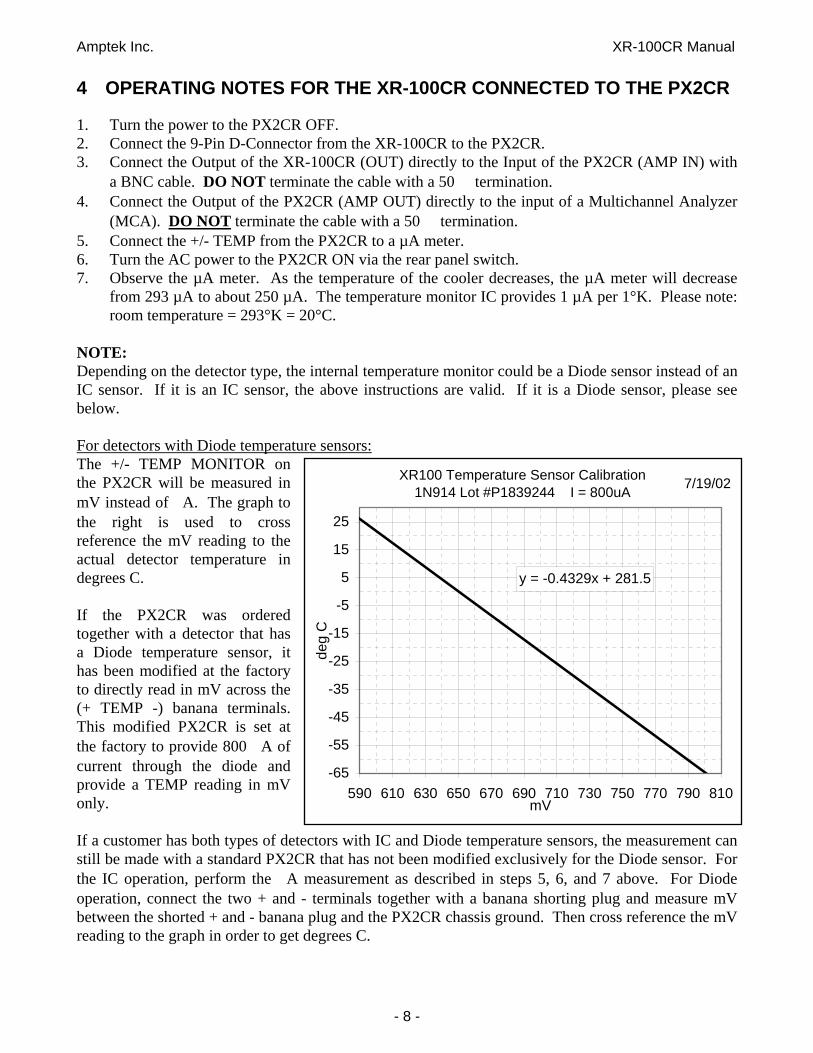
4 OPERATING NOTES FOR THE XR-100CR CONNECTED TO THE PX2CR 1. Turn the power to the PX2CR OFF. 2. Connect the 9-Pin D-Connector from the XR-100CR to the PX2CR. 3. Connect the Output of the XR-100CR (OUT) directly to the Input of the PX2CR (AMP IN) with
a BNC cable. DO NOT terminate the cable with a 50 termination. 4. Connect the Output of the PX2CR (AMP OUT) directly to the input of a Multichannel Analyzer
(MCA). DO NOT terminate the cable with a 50 termination. 5. Connect the +/- TEMP from the PX2CR to a µA meter. 6. Turn the AC power to the PX2CR ON via the rear panel switch. 7. Observe the µA meter. As the temperature of the cooler decreases, the µA meter will decrease
from 293 µA to about 250 µA. The temperature monitor IC provides 1 µA per 1°K. Please note: room temperature = 293°K = 20°C.
NOTE: Depending on the detector type, the internal temperature monitor could be a Diode sensor instead of an IC sensor. If it is an IC sensor, the above instructions are valid. If it is a Diode sensor, please see below. For detectors with Diode temperature sensors: The +/- TEMP MONITOR on the PX2CR will be measured in mV instead of A. The graph to the right is used to cross reference the mV reading to the actual detector temperature in degrees C. If the PX2CR was ordered together with a detector that has a Diode temperature sensor, it has been modified at the factory to directly read in mV across the (+ TEMP -) banana terminals. This modified PX2CR is set at the factory to provide 800 A of current through the diode and provide a TEMP reading in mV only. If a customer has both types of detectors with IC and Diode temperature sensors, the measurement can still be made with a standard PX2CR that has not been modified exclusively for the Diode sensor. For the IC operation, perform the A measurement as described in steps 5, 6, and 7 above. For Diode operation, connect the two + and - terminals together with a banana shorting plug and measure mV between the shorted + and - banana plug and the PX2CR chassis ground. Then cross reference the mV reading to the graph in order to get degrees C.
XR100 Temperature Sensor Calibration1N914 Lot #P1839244 I = 800uA
y = -0.4329x + 281.5
-65
-55
-45
-35
-25
-15
-5
5
15
25
590 610 630 650 670 690 710 730 750 770 790 810mV
deg
C
7/19/02

Amptek Inc. XR-100CR Manual
- 9 -
8. Once the temperature has stabilized (about one minute), start taking data on the MCA. For normal operation, there is no need to monitor the temperature. In order to avoid extraneous noise pick-up into the detector, disconnect the +/-TEMP wires from the PX2CR. Just turn the power ON to the PX2CR, wait a few seconds and start taking data.
9. The XR-100CR can be stimulated by either an X-Ray source or through the TEST input connector. A positive (100 ns rise, 1 ms fall) test pulse of 20 mV will produce an output from the XR-100CR roughly equivalent to a 20 keV X-Ray.
NOTE: For 5 mm2 and 25 mm2 detectors (500 m thick) with internal collimators only: Set the pulse generator to 4 Volts and the PX2CR GAIN to 2. This will produce an output from the AMP OUT of the PX2CR of about 1 Volt.
10. Please Note: The standard PX2CR Shaping Amplifier has a "triangular" fixed shaping time constant of about 12 µs, (see graph below). Optional PX2CR with 6 µs or 20 µs shaping time constants are also available. An external NIM amplifier, compatible with a reset type preamplifier, can also be used if other shaping time constants are desirable. Power to the XR-100CR can be supplied through the PX2CR even if an external amplifier is used.
Pulse Widths: 12 s Shaper: 22 s 6 s Shaper: 15 s 20 s Shaper: 54 s

Amptek Inc. XR-100CR Manual
- 10 -
5 RISE TIME DISCRIMINATION (RTD) IN THE PX2CR AMPLIFIER A Rise Time Discriminator circuit has been implemented in the PX2CR amplifier. See Specifications under THEORY OF OPERATION. When RTD is active (RTD switch up on the front panel), the shaped pulses are internally gated and only pulses corresponding to "good" X-Ray events are allowed to be sent to the MCA for analysis. The RTD internal threshold is set to about 2 keV. If energies less than 2 keV are to be detected do not use the RTD function. The graph bellow shows the shape of the output pulse when RTD is activated.
6 PILEUP REJECTION (PU) IN THE PX2CR AMPLIFIER A PileUp rejection circuit has been implemented in the PX2CR amplifier. The PU Gate located in the back panel of the PX2CR produces a positive TTL pulse. DO NOT terminate this signal with 50 . The PU Gate should be connected to a device of impedance greater than 1 k . For the duration of this gate, the Multichannel Analyzer (MCA) must reject any detected pulse. The PU Gate at the back of the PX2CR (bottom trace in plot) also combines the gate-off pulse to the MCA due to the reset preamplifier (see next page). When using the AMPTEK MCA8000 or MCA8000A Multichannel Analyzer, the PU Gate from the PX2CR should be connected to GATE 1 of the MCA.

Amptek Inc. XR-100CR Manual
- 11 -
7 INPUT COUNT RATE (ICR) IN THE PX2CR AMPLIFIER The Input Count Rate (ICR) pulse (bottom trace in plot) is provided through a rear panel BNC connector in the PX2CR amplifier. This pulse is produced from a fast low level discriminator which is set just above the noise threshold of the XR-100CR preamplifier. The ICR pulse is a positive TTL type with maximum duration of 2 µs. DO NOT terminate this signal with 50 . The ICR should be connected to a device of input impedance greater than 1 k . When connected to a counter, the ICR counting rate corresponds to the total number of X-ray events that strike the detector. The ICR can be used together with the RTD and PU in order to calculate absolute rates.

Amptek Inc. XR-100CR Manual
- 12 -
8 XR100CR / PX2CR Reset Waveforms 1. Typical waveform at the output of the XR-100CR 2. Reset pulse at the output of the XR-100CR 3. Reset pulse at the output of the PX2CR. Use
PU GATE to gate-off the MCA (GATE 1 for Amptek MCA8000A)

Amptek Inc. XR-100CR Manual
- 13 -
9 XR-100CR / PX2CR TROUBLESHOOTING The XR-100CR / PX2CR system has undergone extensive testing and burn-in before leaving the factory. If the performance of the system is not similar to the one recorded at the factory before shipping, please perform the following tests: IMPORTANT: AT ALL TIMES, BOTH CONNECTIONS FROM THE XR-100CR TO THE PX2CR AND FROM THE PX2CR TO THE MULTICHANNEL ANALYZER (MCA), SHOULD BE MADE DIRECTLY AND NOT WITH A 50 TERMINATION. PLACE THE XR-100CR AWAY FROM THE PX2CR, AND AWAY FROM ANY COMPUTER TERMINAL OR CRT MONITOR. KEEP THE XR100CR DETECTOR AWAY FROM MAGNETIC FIELDS. 1. Remove all X-Ray sources. Turn RTD OFF. 2. Connect the XR-100CR output to the PX2CR input. Connect the PX2CR output to a high
impedance input (NOT THROUGH 50 ) of an oscilloscope. Look for periodic noise pick-up on the scope by changing the time-base dial on the scope back and forth. If you find any periodic signal on the scope (other than the Reset Waveforms), try to eliminate its source or place the XR-100CR away from the pick-up area. Any periodic signal detected on the scope will degrade the resolution of the XR-100CR.
3. If no periodic signal is present, and the system is still not performing as designed, proceed to the
next step. 4. Set the gain of the PX2CR to 6.60. Connect the output of the PX2CR directly to the input of a
good, wide bandwidth RMS Voltmeter. If the reading is between 50-60 mVolts RMS (for a standard 7 mm2 detector), the unit is normal. If the RMS reading is high and there is no periodic pick-up signal at the output of the PX2CR, then the detector has been damaged.
CONTACT THE FACTORY FOR FURTHER ASSISTANCE AND RETURN PROCEDURES

Amptek Inc. XR-100CR Manual
- 14 -
10 XR-100CR CONNECTION DIAGRAM WITHOUT PX2CR (Figure 2)
AM
PTE
KXR
-100
CR
TEST
(INPU
T)
OU
T
BN
C
BN
C
LEM
OSHA
PIN
GA
MPL
IFIE
R
PULS
EG
ENER
ATO
R
OSC
ILLO
SCO
PESE
RIA
L PO
RT
CO
NTR
OL
and
DIS
PLAY
PER
SON
AL C
OM
PUTE
RD
ESKT
OP,
LAP
TOP,
HP2
00LX
PRE-
AM
PLIF
IER
POW
ER S
UPP
LY+/
- 9 V
OLT
SD
UA
L TR
AC
KIN
G
DET
ECTO
RB
IAS
SUPP
LY0-
110
VOLT
S, 1
0uA
VAR
IAB
LE
CO
OLE
R P
OW
ER
Typi
cal f
or 1
-sta
ge c
oole
rI =
0.8
AV
= 1.
4 V
Typi
cal f
or 2
-sta
ge c
oole
rI =
0.3
50 A
V =
3.5
V
TEM
P M
ON
ITO
R
0 to
400
μA
for I
C -
AD
590
0.5
V to
1 V
for D
iode
Pocket MCA
MCA8000A
AMPTEK
INP
UT
DE
9I/O
SE
RIA
L P
OR
T

Amptek Inc. XR-100CR Manual
- 15 -
11 OPERATING NOTES FOR THE XR-100CR WITHOUT THE PX2CR 11.1 Equipment Required
1. Power Supplies i. A dual tracking +/-9 VDC @ 35 mA with voltage meter & current limit. ii. A zero to +3 VDC @ 0.7 A adjustable with voltage and current meter. iii. A zero to +110 VDC adjustable @ 10 µA.
1. A zero to 400 µA DC meter with high input impedance (>1000 M ). 2. Shaping amplifier such as NIM standard Shaping Amplifier with an input impedance of 1 k .
A "triangular" type of pulse with 12 µs shaping time and base line restoration will be needed to realize the resolution of the XR-100CR. Example: Canberra Model 2025 or 2026.
3. Oscilloscope 4. A low energy radioactive x-ray source or tail pulse generator. 5. AC power outlet strip (preferably with surge suppression & EMI/RFI filtering).
11.2 Absolute Maximum Ratings Cooler power.............+0.7 AMPS Preamp power...........+/- 9 VOLTS Detector Bias (HV)....+110 VOLTS 11.3 6-Pin Lemo Connector on the XR-100CR (Lemo Part# ERA.1S.306.CLL) Pin 1: Temperature Monitor Pin 2: + H.V. Detector Bias, +110 Volt max. Pin 3: -9 Volt Preamp Power Pin 4: +9 Volt Preamp Power Pin 5: Cooler Power Return Pin 6: Cooler Power (0 to +2.1 Volt @ 0.7 A max.) CASE: Ground and Shield 11.4 9-Pin Cable D-Connector to PX2CR or External Power (standard 9-Pin D) Pin 1: +9 Volt Preamp Power Pin 2: -9 Volt Preamp Power Pin 3: 0 to +2.1 Volt Cooler Power @ 0.7 A max. Pin 4: + 9 Volt Temperature Monitor Power Pin 5: + H.V. Detector Bias, +110 Volt max. Pin 6: Ground and Case Pin 7: Cooler Power Return Pin 8: Ground and Case Pin 9: Ground and Case 11.5 Connections and Turn-On Procedure (see figure 2)
1. Turn all power supplies OFF. Plug all equipment to be used into one common AC power outlet strip. This will help prevent ground loops, which is crucial in getting good performance from the XR-100CR.
2. Set voltages on all power supplies to ZERO. Set current limits on all power supplies to ZERO.

Amptek Inc. XR-100CR Manual
- 16 -
3. Connect the LEMO CONNECTOR cable to the XR-100CR. Apply power to the XR-100CR through the D-CONNECTOR end of the cable according to Figure 2 and the Pin assignments given above in the manual.
4. Turn ON the +/-9 VDC power supplies to power the charge sensitive preamplifier. Verify that both the + and - Volt outputs are between 8 and 9 Volts. NEVER EXCEED 9 VOLTS. Increase the current limit on the power supplies as required so that it can just obtain this output voltage but will not allow any excessive current to flow.
5. Set the High Voltage Supply to zero. Slowly increase voltage to be between +35 and +45 volts.
6. Attach the OUTPUT of the XR-100CR to the INPUT of the shaping amplifier. A BNC connector is provided on the rear panel of the XR-100CR. The output pulses of the XR-100CR are NEGATIVE. A NIM standard shaping amplifier compatible with a reset type preamplifier and an input impedance of 1 k can be used. A shaping time constant of 12 µs or longer and "triangular" shaping with Base Line Restoration is optimum for this detector.
7. Attach the OUTPUT of the shaping amplifier to an oscilloscope. Observe that the output of the shaping amplifier is random noise. Make sure there is no repetitive signal such as the power line frequency or any type of RF signal. Any repetitive signal observed can be traced to ground loops or RFI generated from equipment such as computer monitors. If any repetitive signals are present, other than the “Reset Waveforms” described earlier in the manual, the performance of the XR-100CR will degrade significantly.
8. If the testing is to be done with a radioactive source, remove the red protective cover from the detector of the XR-100CR. Place the radioactive source in front of the AXRCR detector.
9. If a pulse generator is to be used, connect the OUTPUT of the pulse generator to the BNC TEST input of the XR-100CR. Set the test pulse generator to produce a 20 mV peak signal at a frequency of about 1 kHz. The rise time of the signal should be about 100 ns and the pulse width should be for about 1 ms. This will produce a pulse out of the XR-100CR equal to approximately a 20 keV X- ray event. Observe pulses on the oscilloscope.
NOTE: For 5 mm2 and 25 mm2 detectors (500 m thick) with internal collimators only: Set the pulse generator to 4 Volts. Set the PX2CR GAIN to 2. This will produce an output from the AMP OUT of the PX2CR of about 1 Volt.
10. Connect the + terminal of the temperature monitor µA meter to the + 8 Volt supply through a 10 k resistor. See Figure 1. Connect the - terminal of the meter to Pin 4 of the D-Connector in order to power the temperature monitor circuit. Observe that the reading in µA is approximately the room temperature in degrees KELVIN. (i.e. 300 µA corresponds to 300 K room temperature)
11. While observing the µA meter, slightly increase the cooler supply current until the temperature reading starts to change on the µA meter. Observe that the temperature is DECREASING. If the temperature increases, turn OFF the power supply and check the polarity of the cooler power wires. If the temperature is decreasing, increase the +3 V supply while observing the current. The current should be between +650 and +700 mA. The temperature displayed on the µA meter should decrease to about 250 K.
12. THE COOLER IS FRAGILE AND WILL BE PERMANENTLY DAMAGED IF EXCESSIVE CURRENT OR IF REVERSE POLARITY IS APPLIED. THE WARRANTY WILL BE VOID IF THE COOLER IS DAMAGED DUE TO EXCESSIVE CURRENT OR REVERSE POLARITY.
13. The temperature sensor has an offset associated with it. It is quite linear but it could have an offset of about 5 degrees Kelvin.

Amptek Inc. XR-100CR Manual
- 17 -
14. Also, once the temperature on the AXRCR gets below -10 °C the performance of the XR-100CR system will not change with a temperature variation of a few degrees. Hence, accurate temperature control is not necessary.
15. Increase the + H.V. supply to + 100 Volts. Now the XR-100CR is fully operational. 16. ALWAYS INCREASE THE + H.V. POWER SLOWLY TO PROTECT THE INPUT FET.
WHEN TURNING OFF THE XR-100CR, DECREASE THE + H.V. SLOWLY TO ZERO VOLTS BEFORE TURNING OFF THE XR-100CR. IF THE FET IS DAMAGED DUE TO HIGH VOLTAGE TRANSIENTS, THE WARRANTY WILL BE VOID.
12 PROCEDURE TO LOWER THE HIGH VOLTAGE BIAS IN THE
DETECTOR If the detector starts to breakdown or becomes noisy, it is probably the result of increased leakage current which may occur after exposure to accumulated radiation. The exact reason and the total radiation that will cause this increase of leakage current in the detector is very complex since it depends on the energy spectrum and intensity of radiation the detector was exposed to. Lowering the High Voltage bias from the factory set +100 Volts to 80-90 Volts can reduce the detector leakage. Please follow the instructions below:
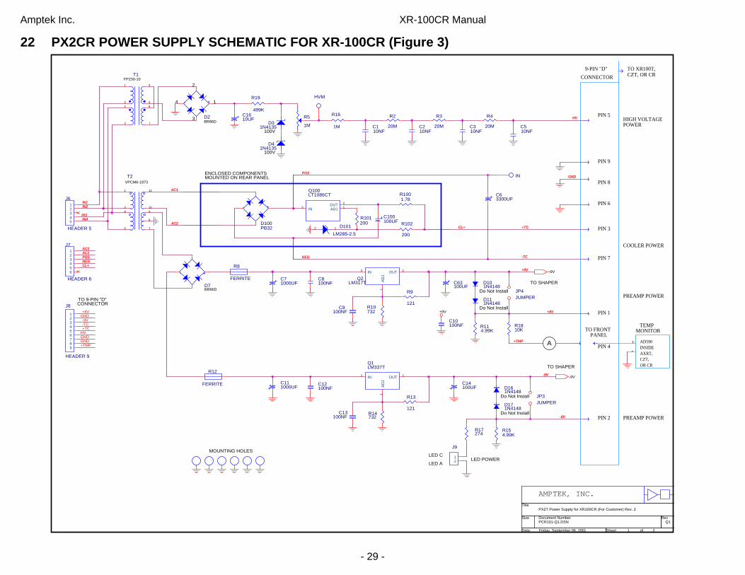
Refer to the “Power Supply Schematic” (figure 3) included in this manual. Unplug the PX2CR from AC power. Unplug the XR-100CR from the PX2CR. Open the PX2CR by removing the two screws from the bottom of the case. Locate the D3 and D4 zener diodes on the PX2CR mother board just below the input AC filter. Unsolder one of the connections on D3 or D4 so that no connection from R16 to ground is made. These two zener diodes set the high voltage to the detector. By removing the connection to ground the voltage is now set by the Potentiometer R5.
Turn POWER ON.
CAUTION: HIGH VOLTAGE AND AC LINE VOLTAGE ARE PRESENT. DO NOT TOUCH ANYTHING INSIDE THE PX2CR WITH BARE FINGERS. USE AN INSULATED SCREWDRIVER AND TEST LEADS.
With a high impedance voltmeter (>1000 M ) measure the detector bias voltage from the outside of the PX2CR at the 9-PIN D-Connector between Pins 5 and 8. It should be about +100 Volts. If a high impedance voltmeter is not available, use a standard 10 M input impedance meter and measure the voltage at the HVM point just next to R5.
Potentiometer R5 is located on the motherboard of the PX2CR in the back just below the AC input filter. This potentiometer adjusts the high voltage to the detector. With an INSULATED screwdriver turn the potentiometer's screw counter-clockwise to reduce the voltage to the detector by about 10 volts. Turn the R5 screw counter-clockwise to set the voltage to +90 Volts. Plug in the XR-100CR. Each time R5 is turned by 1/2 turn check to see if the detector is restored to normal. High voltage to the detector can be decreased by more than 10 volts as long as the resolution of the detector is acceptable.
If this procedure succeeds, operating the detector at the highest voltage below +100 Volts without breakdown is recommended. Once a new stable high voltage level has been established zener diodes D3 and D4 should be replaced with new zeners equal to the new high voltage. If new zeners are not available, leave the zener connection to ground open and operate the PX2CR temporarily without the
Amptek Inc. XR-100CR Manual
- 18 -
zeners. Note that if the input AC line varies too much at your location you might find the detector high voltage to be unstable without the zeners.
NOTE: The 25 mm2 and 5 mm2 (500 m thick) detectors require a normal high voltage bias of between +130 to +150 Volts. 13 WARRANTY AMPTEK, INC. warrants to the original purchaser this instrument to be free from defects in materials and workmanship for a period of one year from shipment. AMPTEK, INC. will, without charge, repair or replace (at its option) a defective instrument upon return to the factory. This warranty does not apply in the event of misuse or abuse of the instrument or unauthorized alterations or repair. AMPTEK, INC. shall not be liable for any consequential damages, including without limitation, damages resulting from the loss of use due to failure of this instrument. All products returned under the warranty must be shipped prepaid to the factory with documentation describing the problem and the circumstances under which it was observed. The factory MUST be notified prior to return shipment. The instrument will be evaluated, repaired or replaced, and promptly returned if the warranty claims are substantiated. A nominal fee will be charged for unsubstantiated claims. Please include the model and serial number in all correspondence with the factory. 13.1 Technical Questions For all technical questions, please contact the factory via PHONE: +1 781 275 2242 FAX: +1 781 275 3470 Email: <[email protected]> www.amptek.com

Amptek Inc. XR-100CR Manual
- 19 -
14 INTERNAL CONNECTIONS BETWEEN AXRCR / XR-100CR / PX2CR
1
2
3
4
5
9
8
6
11
10
7
12
TEMPERATURESENSOR
AD590
ELECTRICCOOLER
THERMO-
FEEDBACK
PREAMP
FILTER
1
2
3
4
5
6
1
2
3
4
5
6
7
8
9
SHAPINGAMP
GND
GND
GND
-9 VDC
+9 VDC
BIAS
COOLER-
COOLER+
TEMP.
DETECTOR
FET
Cf = 40 f F
Ctest = 40 f F 50 ohm
THERMAL SW.
9 PIN DCONN.
LEMOCONN.
XR-100CR PX2CRAXRCR
OUT
TEST
POWERIEC 320
AMPOUT
AC IN
X-RAYS
Be
CASE
ICR
PUGATE
RISE-TIMEDISC.
12 11 10
4 5 6
123
9
7 12
3
45
6
8
5 4 3 2 1
9 8 7 6
9 position DLemoTO-8
Top View End View Front View (female)

Amptek Inc. XR-100CR Manual
- 20 -
15 PX2CR FRONT AND BACK PANELS
PX2T/CR Front Panel
PX2T/CR Back Panel
To change selected voltage: Remove fuse cartridge using a small blade screwdriver or similar tool; select desired voltage by matching arrow on fuse cartridge with indicator located on bezel (lower left corner); replace fuse cartridge making sure the desired voltage arrow aligns with the indicator.
MODEL PX2T/CR POWER SUPPLY & AMPLIFIER
FOR THE XR-100T/CR Si DETECTOR
+ TEMP - MONITOR POWER
GAIN XR100T/CR
AMP TEK
AMP IN AMP OUT
RTD
PU GATE
MODEL# PX2T-CR
SERIAL # 000
AMPTEK INC.
6 De ANGELO DR.
BEDFORD, MA 01730 U.S.A.
ICR
o _
14 DEANGELO DR.

Amptek Inc. XR-100CR Manual
- 21 -
16 XR-100CR EFFICIENCY CURVES The figure on the left (linear scale) shows the intrinsic full energy detection efficiency for the XR-100CR detectors. This efficiency corresponds to the probability that an X-ray will enter the front of the detector and deposit all of its energy inside the detector via the photoelectric effect.
The figure on the left (log scale) shows the probability of a photon undergoing any interaction, along with the probability of a photoelectric interaction which results in total energy deposition. As shown, the photoelectric effect is dominant at low energies but at higher energies above about 40 keV the photons undergo Compton scattering, depositing less than the full energy in the detector. Both figures above
combine the effects of transmission through the Beryllium window (including the protective coating), and interaction in the silicon detector. The low energy portion of the curves is dominated by the thickness of the Beryllium window, while the high energy portion is dominated by the thickness of the active depth of the Si detector. Depending on the window chosen, 90% of the incident photons reach the detector at energies ranging from 2 to 3 keV. Depending on the detector chosen, 90% of the photons are detected at energies up to 9 to 12 keV.

Amptek Inc. XR-100CR Manual
- 22 -
17 APPLICATION NOTES 17.1 Use of Collimators
X-ray events that are produced near the edges of a detector may result in partial charge collection. Hence, a typical “tail” is observed at the low energy side of an energy peak. This “tail” is often called the “Background.” In the case of the 55Fe, the ratio of the counts at the 5.9 keV peak to the counts at about 2 keV is called the “Peak to Background Ratio” (P/B). The XR-100CR with a 7 mm2 uncollimated detector exhibits a P/B = 260. However, the same detector with an external Aluminum collimator having a 2 mm diameter hole has a P/B = 3150. See Figure below. The use of a collimator increases the signal to noise ratio of X-ray events that fall on the low energy tails of higher peaks, and thus, increasing the counting statistics in observing such events. As shown below, the 4.2 keV Silicon escape peak from the 5.9 keV is better defined with a collimated detector than with an uncollimated one. Furthermore, the 4.7 keV Silicon escape peak is clearly visible with the collimated detector, and not visible at all with the uncollimated detector. Collimators can be made from materials other than Aluminum, like Copper, Tungsten, Silver or other, provided the fluorescence peaks from the collimator material do not interfere with the anticipated measurement. In cases where fluorescence peaks produced from the edges of collimators need to be minimized or eliminated, a multilayer collimator can be made by progressively using lower Z materials. Each layer will act as an absorber to the fluorescence peaks of the previous layer. The final layer will be of the lowest Z material whose fluorescence peaks are of low enough energy to be outside the anticipated X-ray detection range.
XR100CR with and without Collimator55Fe Spectrum
1
10
100
1000
10000
100000
0.0 1.0 2.0 3.0 4.0 5.0 6.0 7.0
ENERGY (keV)
CO
UN
TS (L
OG
) Without CollimatorWith Collimator
5.9 keVP5.9keV
B2.0keV_____ Without Collimator = 260:1
With Collimator = 3150:1
Peak to Background Ratio
4.2 keVSi Escape Peak

Amptek Inc. XR-100CR Manual
- 23 -
17.2 Detector Edge Effects (25mm2 and 5mm2, 500 m thick) The 25 mm2 / 5 mm2 X 500 m thick detectors exhibit different "edge effects" than the standard
7 mm2 / 300 m detector. An edge effect event is produced at the edge of the detector and results in a pulse of partial charge collection. In the 7 mm2 / 300 m detectors, these events give rise to a "tail" at the low energy side of the energy peak. In order to reduce leakage current and improve resolution the new detector incorporates a grounded guard ring around the active 25 mm2 / 5 mm2 detection area. This guard-ring terminates the edges so uniformly that many edge effect pulses tend to produce a secondary peak rather than creating a random background tail.
The figures below, in log and linear scales, show the typical 55Fe spectrum taken with the 7 mm2 / 300 m and 25 / 5 mm2 500 m detectors. The 4.2 keV Si-escape peaks (5.9 keV - 1.7 keV/kaSi = 4.2 keV) are very similar in both detectors. The 3.3 keV secondary peak in the 25/5 mm2 detector represents 1.2% of the total counts under the 5.9 keV peak. The energy of the secondary peak is always 56% that of a particular primary energy peak. Please note that although four times the area, the 25 mm2 / 500 m detector exhibits a lower background at the low energy side of the secondary peak than the 7 mm2 / 300 m detector. It appears that the area between the two backgrounds, between 1 and 3 keV, is equal to the area under the 3.3 keV secondary peak. Although a small effect, in order to eliminate the secondary peak, an internal silver (Ag) collimator is now used on all 25 / 5 mm2 detectors. An external collimator is always possible and on special order Amptek can incorporate other materials for specific applications.
Amptek Inc. XR-100CR Manual
- 24 -
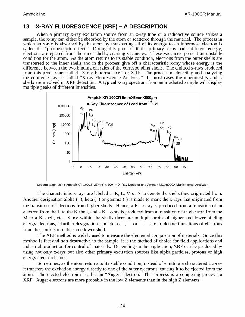
18 X-RAY FLUORESCENCE (XRF) – A DESCRIPTION When a primary x-ray excitation source from an x-ray tube or a radioactive source strikes a
sample, the x-ray can either be absorbed by the atom or scattered through the material. The process in which an x-ray is absorbed by the atom by transferring all of its energy to an innermost electron is called the “photoelectric effect.” During this process, if the primary x-ray had sufficient energy, electrons are ejected from the inner shells, creating vacancies. These vacancies present an unstable condition for the atom. As the atom returns to its stable condition, electrons from the outer shells are transferred to the inner shells and in the process give off a characteristic x-ray whose energy is the difference between the two binding energies of the corresponding shells. The emitted x-rays produced from this process are called “X-ray Fluorescence,” or XRF. The process of detecting and analyzing the emitted x-rays is called “X-ray Fluorescence Analysis.” In most cases the innermost K and L shells are involved in XRF detection. A typical x-ray spectrum from an irradiated sample will display multiple peaks of different intensities.
Spectra taken using Amptek XR-100CR 25mm2 x 500 m X-Ray Detector and Amptek MCA8000A Multichannel Analyzer.
The characteristic x-rays are labeled as K, L, M or N to denote the shells they originated from. Another designation alpha ( ), beta ( ) or gamma ( ) is made to mark the x-rays that originated from the transitions of electrons from higher shells. Hence, a K x-ray is produced from a transition of an electron from the L to the K shell, and a K x-ray is produced from a transition of an electron from the M to a K shell, etc. Since within the shells there are multiple orbits of higher and lower binding energy electrons, a further designation is made as , or , etc. to denote transitions of electrons from these orbits into the same lower shell. The XRF method is widely used to measure the elemental composition of materials. Since this method is fast and non-destructive to the sample, it is the method of choice for field applications and industrial production for control of materials. Depending on the application, XRF can be produced by using not only x-rays but also other primary excitation sources like alpha particles, protons or high energy electron beams. Sometimes, as the atom returns to its stable condition, instead of emitting a characteristic x-ray it transfers the excitation energy directly to one of the outer electrons, causing it to be ejected from the atom. The ejected electron is called an “Auger” electron. This process is a competing process to XRF. Auger electrons are more probable in the low Z elements than in the high Z elements.
Amptek XR-100CR 5mmX5mmX500μmX-Ray Fluorescence of Lead from 109Cd
1
10
100
1000
10000
100000
1000000
0 8 15 23 30 38 45 53 60 67 75 82 90 97
Energy (keV)
Cou
nts
(Log
)
PbLα
PbLβ
PbLγ
109Cd Pbkα2
Pbkα1 Pb
kβ1
109Cd88
22.1
25

Amptek Inc. XR-100CR Manual
- 25 -
3) When a vacancy is created in the L shell by either the primary excitation x-ray or by the previous event, an electron from the M or N shell “jumps in” to occupy the vacancy. In this process, it emits a characteristic x-ray unique to this element and in turn, produces a vacancy in the M or N shell.
2) An electron from the L or M shell “jumps in” to fill the vacancy. In the process, it emits a characteristic x-ray unique to this element and in turn, produces a vacancy in the L or M shell.
X-Ray Fluorescence Process Example: Titanium Atom (Ti = 22)
1) An electron in the K shell is ejected from the atom by an external primary excitation x-ray, creating a vacancy.
“Auger” Electron The excitation energy from the inner atom is transferred to one of the outer electrons causing it to be ejected from the atom.

Amptek Inc. XR-100CR Manual
- 26 -
19 XR-100CR-EX1.5 MECHANICAL DIMENSIONS
All Dimensions Are In Inches Except As Noted
KEY TAB
DETECTOR ORIENTATIONNOTE KEY TAB

Amptek Inc. XR-100CR Manual
- 27 -
20 XR-100CR SELECTION CHART (as of July 2008)

Amptek Inc. XR-100CR Manual
- 28 -
21 AMPTEK K AND L EMISSION LINE LOOKUP CHART
Amptek Inc. XR-100CR Manual
- 29 -
- +
D2BR86D
AC1
R3
20M
PIN 5
AC2
C1610UF
Do Not Install
TO XR100T,CZT, OR CR
D31N4135
R9
121
AC1
J9
12
Do Not Install
R114.99K
IN1
PREAMP POWER
+9V
GND
- +
D100PB32
R13
121
+8V
-8V
PIN 2
3
IN3
CL+
AD590INSIDEAXRT,CZT,OR CR
LED C
-TC
GND
C9100NF
D171N4148
CONNECTOR
CL+
HVMR19
499K
Do Not Install
CONNECTOR
+A
+9V
Q1LM337T
1
2 3
AD
JIN OUT
R2
20M
LED POWER
-TC
C8100NF
+9V
HV
R17274
MOUNTING HOLES
D111N4148
C110NF
C111000UF
TO SHAPER
9-PIN "D"
C510NF
R10732
AMPTEK, INC.
C63300UF
IN
TEMPMONITOR
IN4
+8V
R14732
Q2LM317T
1
3 2
AD
J
IN OUT
J6
HEADER 5
12345
D101LM285-2.5
3 2
R16
1M
GND
4
PCR101-Q1.DSN Q1
PX2T Power Supply for XR100CR (For Customer) Rev. 2
1 2Friday, September 06, 2002
Title
Size Document Number Rev
Date: Sheet of
LED A
C13100NF
C14100UF
R12
FERRITE
PIN 9
NEG
PIN 6
+TMP
C100100UF
TO 9-PIN "D"
R102
200
C63100UF
100V
D161N4148
HIGH VOLTAGEPOWER
C71000UF D10
1N4148
COOLER POWER
R5
1M
POS
GND
PIN 1
HV
+TC
-9V
J8
HEADER 9
123456789
JP3JUMPER
POS
R1001.78
PIN 7
T1FP230-101
3
42
5
68
7
C12100NF
D41N4135
C310NF
.
PIN 8
AC2
1
NEG
C10100NF
-
PIN 3
R1810K
J7
HEADER 6
123456
Do Not Install
+TC
TO SHAPER
IN2
T2VPCM6-1873
1
6
43
12
109
7
8
PIN 4
TO FRONT PANEL
100V
JP4JUMPER
ENCLOSED COMPONENTS
R8
FERRITE
-9V
-8V
- +
D7BR86D
R101200
PREAMP POWER
R154.99K
Q100LT1086CT
132
ADJINOUT
C210NF
R4
20M
MOUNTED ON REAR PANEL
+TMP
2
22 PX2CR POWER SUPPLY SCHEMATIC FOR XR-100CR (Figure 3)

Amptek Inc. XR-100CR Manual
- 30 -
23 PX2CR SHAPER SCHEMATIC
-
C431NF, NPO
R75 OPEN
+
-
U43
LT12273
26
7
4
+9
R522.80K
GN
ICR
R575.23K
FRONT
+5
R10423.7K
(RTD GND)
R831M
-
R45
3.57K
Q101 2N3906
+9
SHOUT -9V
C492.2UF
PCR101-Q0.DSN Q
Shaper (12uS Shaping) Schematic for XR100CR
2 2Friday, September 06, 2002
Titl
Siz Document Number Rev
Date: Sheet o
2mS
+9
R78 4.7
R41 1.74K
TO BACKPANEL
+9
R63
100
ICR
R6520K
R671K
R74
6.04K
2
+5
GN
GNC5847NF
R72549
R54
6.98K
ICU47B 74HC32
4 5 6
C65
47PF
GN
R73
1K
JP2 JUMPER
R79 4.7
-
R4829.4K
-9V
+5
R55
6.98K
PANEL
+9
D431N4148
OUT
VC
C41A OPEN
R494.87K
+
-
U45AD829 3
26
71
45
+9V
R471.82K
R81
1K
R82
2K
+ -
U41B OP467
5 6
7 4
11
C51-C54,C58-C61 = 47NF
U47D74HC32
12
1311
C5147NF
C67
2.2NF
+9
3
+9
R5810K
J10
HEADER 2 1 2 R50
4.87K
AMPTEK, INC.
C41 4.7NF,NPO
HOLES
C471NF, NPO
J12HEADER3
123
R102
1K
R421K
+
-
U41DOP46712
13 14
4
11
C50
0.22UF
U47A74HC32
1
23
R51
2.37K
(PANEL GND)
TO RTD
D41 SD101CCT-ND
+ -
U42 AD844 3
2 6 7 1
4 8
C57
0.22UF
PUGATE
+9
PUGATE
FROM RTDBOARD
C42
1NF, NPO
R70
49.9K
.
J21
HEADER 2 1 2 -
+5
+9V
R71
4.99K
R4349.9
J5
12 C66
10PF
R77 OPEN
C44 1NF, NPO
R56
1.96K
+
-
U46
LT12273
26
7
4
U48 LM78L05
3 1
2
VI VOUT GND
R5330.9K
-
MOUNTING
+9
J4
HEADER 5
1 2 3 4 5
R10120K
J11HEADER 2
12
SHOUT
R44
3.57K
R641M
+9
GND
-
PUGAT
+
-
U41COP46710
98
4
11
-
R10323.7K
-
C1012.2UF
D42
SD101CCT-ND
R68
1K
TO
-
-
+9
U47C74HC329
108
C46
1NF, NPO
-
C45 1NF, NPO
D1011N4148
+
-
U41AOP4673
21
4
11
DO NOT INSTALL R77 AND C41A
OUT
+5V
-
R80 20K
R661K
R46
2.10K
+9
1