Embed Size (px)
Citation preview

Don't work harder. Work smarter.
CUT-40 PLASMA ARC CUTTER
Revision: AB Issue Date: March 2011 Manual No.: 0-CUT400311
Operating Manual

We Appreciate Your Business. Thank you and congratulations on choosing Smarter Tools. Now you can stop working harder and start working smarter. This Operating Manual has been designed to instruct you on the correct use and operation of your Smarter Tools’ product. Your satisfaction with this product and its safe operation is our ultimate concern. Therefore please take the time to read the entire manual, especially the Safety Precautions. They will help you to avoid potential hazards that may exist when working with this product.
WARNING! READ AND UNDERSTAND ALL SAFETY PRECAUTIONS IN THIS MANUAL BEFORE OPERATING. FAILURE TO COMPLY WITH INSTRUCTIONS IN THIS MANUAL COULD RESULT IN PERSONAL INJURY, PROPERTY DAMAGE, AND/ OR VOIDING OF YOUR WARRANTY. SMARTER TOOLS WILL NOT BE LIABLE FOR ANY DAMAGE BECAUSE OF FAILURE TO FOLLOW THESE INSTRUCTIONS.
Operating Manual Number 0-CUT400311 Smarter Tools CUT-40 Portable Inverter Plasma Cutter Part No. CUT-40 Published by: Smarter Tools, Inc. 12195 Harley Club Drive Ashland, VA 23005 (804) 798.8588 www.usesmartertools.com Copyright © 2011 by Smarter Tools, Inc. Reproductions of this work, in whole or in part, without written permission of the publisher are strictly prohibited. The publisher does not assume and herby disclaims any liability to any party for any loss or damage caused by any error or omission in this Manual, whether such error results from negligence, accident, or any other cause. Publication Date: 03.30.11

Table of Contents SECTION 1: SAFETY INSTRUCTIONS AND WARNINGS .......................... 1-1 1.1 Symbol Usage ......................................................................................... 1-1 1.2 Plasma Cutting Hazards .......................................................................... 1-2 1.3 Additional Symbols for Installation, Operation, and Maintenance ............ 1-7 1.4 Principal Safety Standards ...................................................................... 1-9 1.5 Eye Protection ......................................................................................... 1-9 1.6 Protective Clothing .................................................................................. 1-11 1.7 EMF Information ...................................................................................... 1-13 1.8 General Precautionary Label ................................................................... 1-14 SECCIÓN 1: INSTRUCCIONES DE SEGURIDAD Y ADVERTENCIAS ...... 1-1A 1.1 Símbolo de uso ....................................................................................... 1-1A 1.2 Peligros del corte del plasma .................................................................. 1-2A 1.3 Símbolos adicionales para instalación, operación y mantenimiento ........ 1-7A 1.5 Principales normas de seguridad……………………………………………1-9A 1.6 Protección de los ojos………………………………………………………...1-10A 1.7 Ropa de protección ................................................................................. 1-12A 1.8 Información del EMF ............................................................................... 1-13A 1.9 Etiqueta General de precaución .............................................................. 1-14A SECTION 2: INTRODUCTION AND SPECIFICATIONS .............................. 2-1 2.1 Equipment Identification .......................................................................... 2-1 2. 2 Description ............................................................................................. 2-1 2.3 Specifications .......................................................................................... 2-1 2.4 Duty Cycle ............................................................................................... 2-2 2.5 Transportation Methods ........................................................................... 2-2 SECTION 3: INSTALLATION ....................................................................... 3-1 3.1 Selecting a Location ................................................................................ 3-1 3.2 Environment ............................................................................................ 3-1 3.3 Electrical Input Power .............................................................................. 3-2 3.4 Electromagnetic Compatibility ................................................................. 3-3 3.5 Setup for Cutting ..................................................................................... 3-5 3.6 Plasma ARC Cutting (PAC) Set-up ......................................................... 3-5 SECTION 4: OPERATION ............................................................................ 4-1 4.1 General Operation ................................................................................... 4-1 4.2 Front Panel/Controls................................................................................ 4-1 4.3 Back Panel/Power Switch ........................................................................ 4-2 4.4 Operating Instructions ............................................................................. 4-3 Sección 4: Operación .................................................................................. 4-1A 4.1 Funcionamiento general .......................................................................... 4-1A 4.2 Panel Frontal / Controles ......................................................................... 4-1A 4.3 Panel trasero / interruptor de alimentación………………………………...4-2A 4.4 Instrucciones de uso………………………………………………………….4-3A SECTION 5: MAINTENANCE AND TROUBLESHOOTING ........................ 5-1 5.1 Maintenance ............................................................................................ 5-1 5.2 Troubleshooting ....................................................................................... 5-1 5.3 System Schematic ................................................................................... 5-4 5.4 Parts List ................................................................................................. 5-5 SECCIÓN 5: MANTENIMIENTO Y RESOLUCIÓN DE PROBLEMAS ......... 5-1A 5.1 Mantenimiento ......................................................................................... 5-1A 5.2 Solución de problemas ........................................................................... 5-1A

5.3 Esquema del sistema .............................................................................. 5-6A 5.4 Lista de piezas ........................................................................................ 5-7A

1-1
SECTION 1: SAFETY INSTRUCTIONS AND WARNINGS 1.1 Symbol Usage This manual contains important information that you need to know and understand in order to assure YOUR SAFETY and PROPER OPERATION OF EQUIPMENT. The following symbols help you recognize this information. Please read the manual and pay attention to these sections.
Save These Important Safety Instructions! Read and understand all of these safety instructions. Be sure to retain them for future use.
WARNING! WARNINGS INDICATE A CERTAINTY OR STRONG POSSIBILITY OF PERSONAL INJURY OR DEATH IF INSTRUCTIONS ARE NOT FOLLOWED.
CAUTION: CAUTIONS INDICATE A POSSIBILITY OF EQUIPMENT DAMAGE IF INSTRUCTIONS ARE NOT FOLLOWED PROPERLY.
Note: Notes give helpful information
Welding products and welding processes can cause serious injury or death, or damage to other equipment or property, if the operator does not strictly observe all safety rules and take precautionary actions. Safe practices are outlined in the American National Standard Z49.1 entitled: SAFETY IN WELDING AND CUTTING. This publication and other guides to what you should learn before operating this equipment are listed at the end of these safety precautions. HAVE ALL INSTALLATION, OPERATION, REPAIR WORK, AND MAINTENANCE PERFORMED BY QUALIFIED PROFESSIONALS.

1-2
1.2 Plasma Cutting Hazards The symbols shown below are used throughout this manual to call attention to and identify possible hazards. When you see the symbol, watch out, and follow the related instructions to avoid the hazard. The safety information given below is only a summary of the more complete safety information found in the Safety Standards listed in Section 1-4. Read and follow all Safety Standards. Electric Shock can kill.
Plasma cutters can produce a shock that can cause injury or death. Touching live electrical parts can cause fatal shocks or severe burns. The electrode and work circuit is electrically live whenever the output is on. The input power circuit and machine internal circuits are also live when power is on. In semiautomatic or automatic wire welding, the wire, wire reel, drive roll housing, and all metal parts touching the welding wire are electrically live. Incorrectly installed or improperly grounded equipment is a hazard.
• Do not touch live electrical parts. • Wear dry, hole-free insulating gloves and body protection. • Insulate yourself from work and ground using dry insulating mats or covers
big enough to prevent any physical contact with the work or ground. • Do not use AC output in damp areas, if movement is confined, or if there is a
danger of falling. • Use AC output ONLY if required for the welding process. • If AC output is required; use remote output control if present on unit. • Disconnect input power or stop engine before installing or servicing this
equipment. Lockout/tagout input power according to OSHA 29 CFR 1910.147 (see Safety Standards).
• Properly install and ground this equipment according to its Owner’s Manual
and national, state, and local codes. • Always verify the supply ground – check and be sure that input power cord
ground wire is properly connected to ground terminal in disconnect box or that cord plug is connected to a properly grounded receptacle outlet.
• When making input connections attach proper grounding conductor first –
double-check connections. • Frequently inspect input power cord for damage or bare wiring – replace
cord immediately if damaged – bare wiring can kill. • Turn off all equipment when not in use. • Do not use worn, damaged, undersized, or poorly spliced cables.

1-3
• Do not drape cables over your body. • If earth grounding of the work-piece is required, ground it directly with a
separate cable. • Do not touch torch if you are in contact with the work, ground, or another
torch from a different machine. • Use only well-maintained equipment. Repair or replace damaged parts at
once. Maintain unit according to manual. • Wear a safety harness if working above floor level. • Keep all panels and covers securely in place. • Clamp work cable with good metal-to-metal contact to work-piece or
worktable as near the weld as practical. • Insulate work clamp when not connected to work-piece to prevent contact
with any metal object. • Do not connect more than one torch or work cable to any single output
terminal. SIGNIFICANT DC VOLTAGE exists after removal of input power. • Turn Off inverter, disconnect input power, and discharge input capacitors
according to instructions in Maintenance Section before touching any parts. FUMES AND GASES can be hazardous.
Fumes emitted from the plasma cutting process displace clean air and can result in injury or death. Breathing these fumes and gases can be hazardous to your health.
• Keep your head out of the fumes. Do not breathe the fumes. • If inside, ventilate the area and/or use exhaust at the arc to remove welding
fumes and gases. • If ventilation is poor, use an approved air-supplied respirator.

1-4
• Read the Material Safety Data Sheets (MSDSs) and the manufacturer’s instructions for metals, consumables, coatings, cleaners, and degreasers.
• Work in a confined space only if it is well ventilated, or while wearing an air-
supplied respirator. Always have a trained watchperson nearby. Welding fumes and gases can displace air and lower the oxygen level causing injury or death. Be sure the breathing air is safe.
• Do not weld/cut in locations near degreasing, cleaning, or spraying
operations. The heat and rays of the arc can react with vapors to form highly toxic and irritating gases.
• Do not weld/cut on coated metals, such as galvanized, lead, or cadmium
plated steel, unless the coating is removed from the weld/cut area, the area is well ventilated, and if necessary, while wearing an air-supplied respirator. The coatings and any metals containing these elements can give off toxic fumes if heated.
ARC RAYS can burn eyes and skin.
The plasma cutting arc produces ultraviolet (UV) and infrared (IR) rays that can cause injury to your eyes and skin. Do not look at the plasma cutting arc without proper eye protection.
• Wear a welding helmet fitted with a proper shade of filter to protect your face
and eyes when welding/cutting or watching (see ANSI Z49.1 and Z87.1 listed in Safety Standards 1.4).
• Wear approved safety glasses with side shields under your helmet. • Use protective screens or barriers to protect others from flash and glare;
warn others not to watch the arc. • Wear protective clothing made from durable, flame-resistant material
(leather and wool) and foot protection. CUTTING can cause fire or explosion.
Cutting on closed containers, such as tanks, drums, or pipes, can cause them to blow up. Sparks can fly off from the plasma cutting arc. The flying sparks, hot work-piece, and hot equipment can cause fires and burns. Accidental contact of the torch to metal objects can cause sparks, explosion, overheating, or fire. Check and be sure the area is safe before cutting.

1-5
• Protect yourself and others from flying sparks and hot metal. • Do not cut where flying sparks can strike flammable material. • Remove all flammables within 35 ft (10.7 m) of the plasma cutting arc. If this
is not possible, tightly cover them with approved covers. • Be alert that sparks and hot materials from plasma cutting can easily go
through small cracks and openings to adjacent areas. • Watch for fire, and keep a fire extinguisher nearby. • Be aware that cutting on a ceiling, floor, bulkhead, or partition can cause fire
on the hidden side. • Do not weld/cut on closed containers such as tanks, drums, or pipes; unless
they are properly prepared according to AWS F4.1 (see Safety Standards). • Connect work cable to the work as close to the welding area as practical to
prevent welding current from traveling long, possibly unknown paths and causing electric shock and fire hazards.
• Do not use plasma cutter to thaw frozen pipes. • Wear oil-free protective garments such as leather gloves, heavy shirt, cuff
less trousers, high shoes, and a cap. • Remove any combustibles, such as butane lighters or matches, from your
person before doing any welding. FLYING METAL can injure eyes.
• Cutting, chipping, wire brushing, and grinding cause sparks
and flying metal. As welds cool, they can throw off slag. • Wear approved safety glasses with side shields even under
your welding helmet.
HOT PARTS can cause severe burns.
• Do not touch plasma cut materials with bare hands. • Allow cooling period before working on gun or torch.

1-6
MAGNETIC FIELDS can affect pacemakers.
• Pacemaker wearers keep away. • Wearers should consult their doctor before going near
plasma cutting, arc welding, gouging, or spot welding operations.
NOISE can damage hearing.
• Excessive noise from some processes or equipment can
damage hearing. • Wear approved ear protection if noise level is high.
CYLINDERS can explode if damaged. Shielding gas cylinders contain gas under high pressure. If damaged, a cylinder can explode. Since gas cylinders are normally part of the welding/cutting process, be sure to treat them carefully.
• Protect compressed gas cylinders from excessive heat,
mechanical shocks, slag, open flames, sparks, and arcs. • Install cylinders in an upright position by securing to a
stationary support or cylinder rack to prevent falling or tipping.
• Keep cylinders away from any cutting or other electrical circuits. • Never drape torch over a gas cylinder. • Never allow the torch to touch any cylinder. • Never cut on a pressurized cylinder – explosion will result. • Use only correct shielding gas cylinders, regulators, hoses, and fittings
designed for the specific application; maintain them and associated parts in good condition.

1-7
• Turn face away from valve outlet when opening cylinder valve. • Keep protective cap in place over valve except when cylinder is in use or
connected for use. • Read and follow instructions on compressed gas cylinders, associated
equipment, and CGA publication P-1 listed in Safety Standards. 1.3 Additional Symbols for Installation, Operation, and Maintenance FIRE OR EXPLOSION hazard.
• Do not install or place unit on, over, or near combustible surfaces.
• Do not install unit near flammables. • Do not overload building wiring – be sure power supply system
is properly sized, rated, and protected to handle this unit. FALLING UNIT can cause injury.
• Use handle to lift unit only, NOT running gear, gas cylinders, or
any other accessories. • Use equipment of adequate capacity to lift and support unit. • If using lift forks to move unit, be sure forks are long enough to
extend beyond opposite side of unit.
OVERUSE can cause OVERHEATING
• Allow cooling period; follow rated duty cycle. • Reduce current or duty cycle before starting to cut again. • Do not block or filter airflow to unit.
STATIC (ESD) can damage PC boards.
• Put on grounded wrist strap BEFORE handling boards or parts. • Use proper static-proof bags and boxes to store, move, or ship
PC boards.
1-8
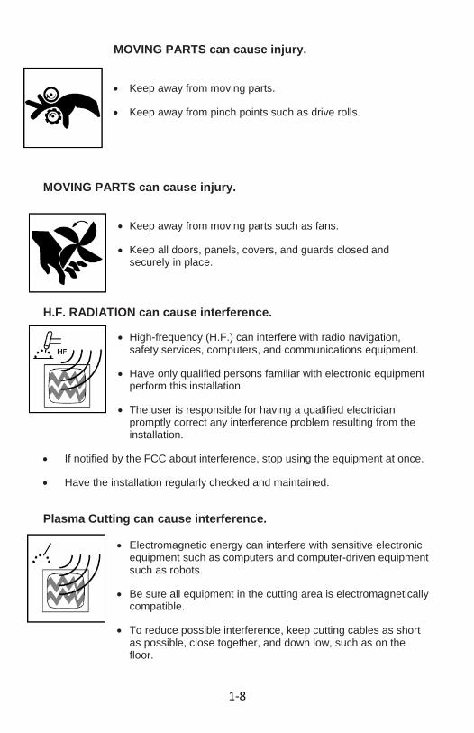
MOVING PARTS can cause injury.
• Keep away from moving parts. • Keep away from pinch points such as drive rolls.
MOVING PARTS can cause injury.
• Keep away from moving parts such as fans. • Keep all doors, panels, covers, and guards closed and
securely in place.
H.F. RADIATION can cause interference. • High-frequency (H.F.) can interfere with radio navigation,
safety services, computers, and communications equipment. • Have only qualified persons familiar with electronic equipment
perform this installation. • The user is responsible for having a qualified electrician
promptly correct any interference problem resulting from the installation.
• If notified by the FCC about interference, stop using the equipment at once. • Have the installation regularly checked and maintained. Plasma Cutting can cause interference.
• Electromagnetic energy can interfere with sensitive electronic
equipment such as computers and computer-driven equipment such as robots.
• Be sure all equipment in the cutting area is electromagnetically
compatible. • To reduce possible interference, keep cutting cables as short
as possible, close together, and down low, such as on the floor.

1-9
Proposition 65 Warning Plasma cutting equipment produces fumes or gases which contain chemicals known to the state of California to cause birth defects and, in some cases, cancer. (California Health & Safety code section 25249.5 et seq.) 1.4 Principal Safety Standards
Safety in Welding and Cutting, ANSI Standard Z49.1, from American Welding Society, 550 N.W. LeJeune Rd., Miami, FL 33126. Safety and Health Standards, OSHA 29 CFR 1910, from Superintendent of Documents, U.S. Government Printing Office, Washington, D.C. 20402. Recommended Safe Practices for the Preparation for Welding and Cutting of Containers That Have Held Hazardous Substances, American Welding Society Standard AWS F4.1, from American Welding Society, 550 N.W. LeJeune Rd., Miami, FL 33126. National Electrical Code, NFPA Standard 70, from National Fire Protection Association, Batterymarch Park, Quincy, MA 02269. Safe Handling of Compressed Gases in Cylinders, CGA Pamphlet P-1, from Compressed Gas Association, 1235 Jefferson Davis Highway, Suite 501, Arlington, VA 22202. Code for Safety in Welding and Cutting, CSA Standard W117.2, from Canadian Standards Association, Standards Sales, 178 Rexdale Blvd, Rexdale, Ontario, Canada M9W 1R3. Safe Practices for Occupation and Educational Eye and Face Protection, ANSI Standard Z87.1, from American National Standards Institute, 1430 Broadway, New York, NY 10018. Cutting and Welding Processes, NFPA Standard 51B, from National Fire Protection Association, Batterymarch Park, Quincy, MA 02269
1.5 Eye Protection Eye and face protectors for welding and related tasks, such as grinding and chipping, should comply with the requirements of ANSI Z87.1. Look for labels or markings indicating compliance. Depending on the specific work task, appropriate eye/face protection may include safety glasses with side protection (side shields or wrap-around frames), goggles, face shields, welding helmets, curtains, or combinations of the above. • Choose a tight fitting helmet to help reduce light reflection into the helmet
through the space between the shell and the head. • Wear the helmet correctly. Do not use it as a hand shield. • Protect the shade lens from impact and sudden temperature changes that
could cause it to crack. • Use a cover lens to protect the filter shade lens. Replace the cover lens if it
gets scratched or hazy. • Make sure to replace the gasket periodically if your helmet uses one. • Replace the clear retaining lens to protect your eyes from broken pieces. • Clean lenses periodically. • Discard pitted or damaged lenses.
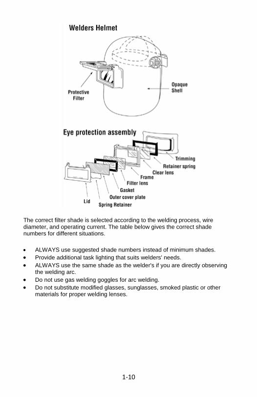
1-10
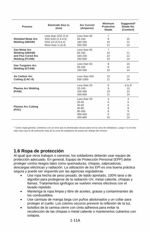
The correct filter shade is selected according to the welding process, wire diameter, and operating current. The table below gives the correct shade numbers for different situations.
• ALWAYS use suggested shade numbers instead of minimum shades. • Provide additional task lighting that suits welders' needs. • ALWAYS use the same shade as the welder's if you are directly observing
the welding arc. • Do not use gas welding goggles for arc welding. • Do not substitute modified glasses, sunglasses, smoked plastic or other
materials for proper welding lenses.

1-11
LENS SHADE SELECTOR Shade numbers are given as a guide only and may be varied to suit individual needs.
*As a rule of thumb, start with a shade that is too dark to see the weld zone. Then go to a lighter shade which gives sufficient view of the weld zone without going below the minimum.
1.6 Protective Clothing Like other jobs or careers, welders must wear suitable protective equipment. In general, Personal Protective Equipment (PPE) must protect against hazards such as burns, sparks, spatter, electric shock, and radiation. The use of PPE is a good safe practice and may be required by regulatory agencies. • Wear clothing made from heavyweight, tightly woven, 100% wool or cotton
to protect from UV radiation, hot metal, sparks and open flames. Flame retardant treatments become less effective with repeated laundering.
• Keep clothing clean and free of oils, greases and combustible contaminants. • Wear long-sleeved shirts with buttoned cuffs and a collar to protect the neck.
Dark colors prevent light reflection. • Tape shirt pockets closed to avoid collecting sparks or hot metal or keep
them covered with flaps.
Process Electrode Size in. (mm)
Arc Current (Amperes)
Minimum Protective
Shade
Suggested* Shade No. (Comfort)
Shielded Metal Are Welding (SMAW)
Less than 3/32 (2.4) 3/32-5/32 (2.4-4.0) 5/32-1/4 (4.0-6.4) More than ¼ (6.4)
Less than 60 60-160 160-250 250-550
7 8
10 11
- 10 12 14
Gas Metal Arc Welding (GMAW) and Flux Cored Arc Welding (FCAW)
Less than 60 60-160 160-250 250-550
7 10 10 10
- 11 12 14
Gas Tungsten Arc Welding (GTAW)
Less than 50 50-100 150-500
8 8
10
10 12 14
Air Carbon Arc Cutting (CAC-A) Less than 500
500-1000 10 11
12 14
Plasma Arc Welding (PAW)
Less than 20 20-100 100-400 400-800
6 8
10 11
6 to 8 10 12 14
Plasma Arc Cutting (PAC)
Less than 20 20-40 40-60 60-80 80-300 300-400 400-800
4 5 6 8 8 9
10
4 5 6 8 9
12 14

1-12
• Pant legs must not have cuffs and must cover the tops of the boots. Cuffs can collect sparks.
• Repair all frayed edges, tears or holes in clothing.

1-13
• Wear high top boots fully laced to prevent sparks from entering into the boots.
• Use fire-resistant boot protectors or spats strapped around the pant legs and boot tops, to prevent sparks from bouncing in the top of the boots.
• Remove all ignition sources such as matches and butane lighters from pockets. Hot welding sparks may light the matches or ignite leaking lighter fuel.
• Wear gauntlet-type cuff leather gloves or protective sleeves of similar material, to protect wrists and forearms. Leather is a good electrical insulator if kept dry.
• Direct any spark spray away from your clothing. • Wear leather aprons to protect your chest and lap from sparks when
standing or sitting. • Wear layers of clothing. To prevent sweating, avoid overdressing in cold
weather. Sweaty clothes cause rapid heat loss. Leather welding jackets are not very breathable and can make you sweat if you are overdressed.
• Wear a fire-resistant skull cap or balaclava hood under your helmet to protect your head from burns and UV radiation.
• Wear a welder's face shield to protect your face from UV radiation and flying particles.
• DO NOT wear rings or other jewelry. • DO NOT wear clothing made from synthetic or synthetic blends. The
synthetic fabric can burn vigorously, melt and produce bad skin burns. Protect all areas of your body from injury during welding or cutting by wearing the proper protective clothing and equipment. Do not weld or cut unless wearing the necessary PPE as specified in this manual and in ANSI Z49.1.
1.7 EMF Information Considerations about Welding and the Effects of Low Frequency Electric and Magnetic Fields Welding current, as it flows through welding cables, will cause electromagnetic fields. There has been and still is some concern about such fields. However, after examining more than 500 studies spanning 17 years of research, a special blue ribbon committee of the National Research Council concluded that: “The body of evidence, in the committee’s judgment, has not demonstrated that exposure to power-frequency electric and magnetic fields is a human-health hazard.” However, studies are still going forth and evidence continues to be examined. Until the final conclusions of the research are reached, you may wish to minimize your exposure to electromagnetic fields when welding or cutting. To reduce magnetic fields in the workplace, use the following procedures:
1. Keep cables close together by twisting or taping them. 2. Arrange cables to one side and away from the operator. 3. Do not coil or drape cables around your body.

1-14
4. Keep welding power source and cables as far away from operator as practical.
5. Connect work clamp to work-piece as close to the weld as possible.
About Pacemakers: Pacemaker wearers consult your doctor first. If cleared by your doctor, then following the above procedures is recommended. 1.8 General Precautionary Label Found on unit and packaging. Do not attempt to remove, destroy, or cover label.

1-1A
SECCIÓN 1: INSTRUCCIONES DE SEGURIDAD Y ADVERTENCIAS 1.1 Símbolo de uso Este manual contiene información importante que necesita conocer y comprender a fin de garantizar su seguridad y funcionamiento adecuado del equipo. Los símbolos siguientes le ayudarán a reconocer esta información. Por favor, lea el manual y prestar atención a estas secciones.
Guarde estas instrucciones de seguridad importantes! Lea y entienda todas las instrucciones de seguridad. Asegúrese de mantenerlas para su uso futuro.
ADVERTENCIA! Las advertencias indican una gran posibilidad de certeza o de lesiones personales o la muerte si no sigue las instrucciones.
ATENCIÓN: PRECAUCIONES INDICAN UNA POSIBILIDAD DE DAÑOS AL EQUIPO Si las instrucciones no se siguen correctamente.
Nota: Toma nota de dar información útil Productos de soldadura y procesos de soldadura puede causar lesiones graves o la muerte, o daños a otros equipos
o la propiedad, si el operador no tiene que observar estrictamente las normas de seguridad y tomar medidas de precaución.
Las normas de seguridad se describen en la Norma Nacional Americana Z49.1 titulado: SEGURIDAD EN LA SOLDADURA Y CORTE. Esta publicación y otras guías sobre lo que usted debe aprender antes de hacer funcionar este equipo se encuentra al final de las medidas de seguridad. TIENE TODAS LAS DE INSTALACIÓN, OPERACIÓN DE TRABAJO DE REPARACIÓN Y MANTENIMIENTO realizado por profesionales calificados

1-2A
1.2 Riesgos de corte por plasma Los símbolos se muestra a continuación se utilizan en este manual para llamar la atención e identificar los posibles peligros. Cuando vea el símbolo, tenga cuidado, y siga las instrucciones correspondientes para evitar el peligro. La información de seguridad dada abajo es solamente un resumen de la información de seguridad más completo que se encuentra en los estandares de seguridad en la Sección 1.4. Lea y siga todas las normas de seguridad. Una descarga eléctrica puede matar.
Cortadoras de plasma puede producir una descarga eléctrica que puede causar lesiones o la muerte. Tocar partes eléctricas vivas puede causar un toque fatal o quemaduras severas. El circuito de electrodo y trabajo está vivo eléctricamente cuando la salida está activada. El circuito de entrada y los circuitos internos de la máquina también están vivos cuando el aparato está encendido. En la soldadura con alambre semiautomática o automática, el alambre, carrete de alambre, la vivienda rodillos de alimentación y todas las partes de metal que tocan el
alambre de soldadura están vivos eléctricamente. Incorrectamente instalados o inadecuadamente a tierra es un peligro. • No tocar las partes eléctricas.
• Use guantes de aislamiento secos y sin huecos y protección del cuerpo.
• Aislar a ti mismo del trabajo y la tierra usando alfombras o cubiertas o
cubiertas suficientemente grande como para prevenir cualquier contacto físico con el trabajo o tierra.
• No use la salida de corriente alterna en áreas húmedas, si el movimiento se
limita, o si existe el peligro de caer.
• Use la salida CA SOLAMENTE si lo requiere el proceso de soldadura.
• Si la salida de CA se requiere utilizar el control remoto si hay uno presente en la unidad.
• Desconecte la corriente de entrada o pare el motor antes de instalar o dar
servicio a este equipo. Bloqueo y etiquetado de alimentación de entrada de acuerdo con OSHA 29 CFR 1910.147 (ver normas de seguridad).
• Instale el suelo y este equipo de acuerdo a sus códigos Manual de
instrucciones y nacionales, estatales y locales.
• Siempre verifique el suministro de tierra - chequee y asegúrese que la potencia de entrada alambre de tierra esté correctamente conectado al terminal de tierra en la caja de desconexión o que su enchufe esté conectado a una toma de toma de tierra adecuada.
• Cuando haga las conexiones de entrada adjuntar conductor de puesta a
tierra primero - doble chequee sus conexiones.
• Frecuentemente inspeccione el cordón de entrada de potencia por daño o por alambre desnudo - reemplace el cordón inmediatamente si está dañado - un alambre desnudo puede matarlo.
• Apague todo equipo cuando no esté en uso.

1-3A
• No utilice desgastados, rotos, o mal los cables empalmados.
• No envuelva los cables alrededor de su cuerpo.
• Si toma de tierra de la pieza de trabajo se requiere conexión de tierra con un
cable separado.
• No toque la antorcha si usted está en contacto con el trabajo, tierra, u otro la antorcha de una máquina diferente.
• Use solamente equipo bien mantenido. Repare o reemplace las piezas
dañadas a la vez. unidad de acuerdo al manual.
• Use un arnés de seguridad si se trabaja sobre el nivel del suelo.
• Mantenga todos los paneles y cubiertas en su sitio.
• El cable de la pinza de trabajo con un buen contacto metal-metal a la pieza de trabajo o mesa de trabajo lo más cerca de la soldadura como sea posible.
• Aísle la abrazadera cuando no están conectados a la pieza de trabajo para
evitar el contacto con cualquier objeto de metal.
• No conecte más de una antorcha o un cable de trabajo a cualquier terminal de salida única.
IMPORTANTE DC VOLTAJE existe después de la eliminación de la
potencia de entrada. • Apague el inversor, desconecte la corriente de entrada y descarga de condensadores de entrada de acuerdo a las instrucciones de la sección de mantenimiento antes de tocar cualquier pieza.
HUMOS Y GASES pueden ser peligrosos. Los humos emitidos por la corte por plasma proceso de desplazar el aire limpio y puede resultar en lesiones o la muerte. Respirando estos humos y gases pueden ser
peligrosos para su salud.
• Mantenga su cabeza fuera del humo. No respirar los vapores.
• Si está adentro, ventile el área y / o el uso de escape en el arco para eliminar los humos y gases de soldadura.
• Si la ventilación es mala, use un respirador aprobado con suministro de aire.
1-4A
• Lea las hojas de seguridad (MSDS) y las instrucciones del fabricante
para los metales, consumibles, recubrimientos, limpiadores y desengrasantes.
• Trabajar en un espacio cerrado solamente si está bien ventilado o mientras esté usando un respirador con suministro de aire. Tenga siempre un watchperson capacitados cerca. Los humos y gases pueden desplazar el aire y bajar el nivel de oxígeno causando daño o la muerte. Asegúrese de que el aire respirable es seguro.
• No soldar / cortar en lugares cerca de desengrase, limpieza o las operaciones de pulverización. El calor y los rayos del arco pueden hacer reacción con los vapores y formar gases altamente tóxicos e irritantes.
• No soldar / cortar en materiales de recubrimientos, como galvanizado, plomo o acero cadmiado, a menos que el recubrimiento se elimina de la soldadura / área de corte, la zona está bien ventilada, y si es necesario, mientras esté usando un respirador con suministro de aire . Los recubrimientos de cualquier metal que contiene estos elementos pueden emanar humos tóxicos cuando se calientan.
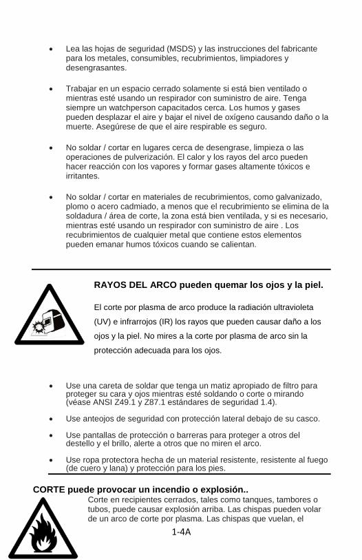
RAYOS DEL ARCO pueden quemar los ojos y la piel. El corte por plasma de arco produce la radiación ultravioleta (UV) e infrarrojos (IR) los rayos que pueden causar daño a los ojos y la piel. No mires a la corte por plasma de arco sin la protección adecuada para los ojos.
• Use una careta de soldar que tenga un matiz apropiado de filtro para proteger su cara y ojos mientras esté soldando o corte o mirando (véase ANSI Z49.1 y Z87.1 estándares de seguridad 1.4).
• Use anteojos de seguridad con protección lateral debajo de su casco. • Use pantallas de protección o barreras para proteger a otros del
destello y el brillo, alerte a otros que no miren el arco. • Use ropa protectora hecha de un material resistente, resistente al fuego
(de cuero y lana) y protección para los pies. CORTE puede provocar un incendio o explosión..
Corte en recipientes cerrados, tales como tanques, tambores o tubos, puede causar explosión arriba. Las chispas pueden volar de un arco de corte por plasma. Las chispas que vuelan, el
1-5A
trabajo en caliente pieza, y el equipo caliente pueden causar fuegos y quemaduras. El contacto accidental de la antorcha a los objetos de metal puede causar chispas, explosión, sobrecalentamiento, o fuego. Chequee y asegúrese que el área es segura antes de cortar. • Protéjase y proteja a otros de las chispas y metal caliente. • No corte, donde las chispas pueden impactar material inflamable. • Quite todo material inflamable dentro de 35 pies (10,7 m) de la corte por
plasma de arco. Si esto no es posible, cúbralo apretadamente con cubiertas aprobadas
• Esté alerta de que las chispas y materiales calientes del corte por plasma
puede ir fácilmente a través de pequeñas grietas y aberturas en las zonas adyacentes.
• Tenga cuidado con el fuego, y mantenga un extinguidor de fuego cerca • Tenga en cuenta que el corte en el techo, piso, pared o partición puede
causar fuego en la cara oculta. • No soldar / cortar en receptáculos cerrados como tanques o tambores o
tubería, a menos que estén debidamente preparados de acuerdo con AWS F4.1 (véase normas de seguridad).
• Conecte el cable de trabajo a la labor tan cerca de la zona de soldadura
como sea posible para evitar que la corriente de soldadura de viajar rutas de largo, posiblemente por partes desconocidas causando una descarga eléctrica y peligro de incendio.
• No utilice el cortador de plasma para descongelar tubos helados. • Use ropa protectiva sin aceite como guantes de cuero, camisa gruesa,
gemelos menos los pantalones, los zapatos de bebé, y una gorra. • Retire todo material combustible, tales como encendedores de butano o
fósforos, de su persona antes de comenzar a soldar.
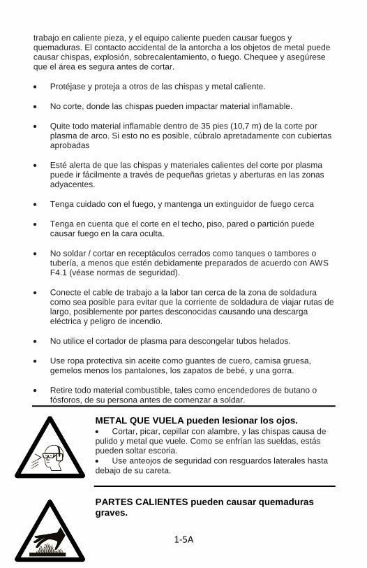
METAL QUE VUELA pueden lesionar los ojos. • Cortar, picar, cepillar con alambre, y las chispas causa de pulido y metal que vuele. Como se enfrían las sueldas, estás pueden soltar escoria. • Use anteojos de seguridad con resguardos laterales hasta debajo de su careta.
PARTES CALIENTES pueden causar quemaduras graves.

1-6A
• No toque los materiales de corte de plasma con las manos desnudas. • Permitir un período de enfriamiento antes de trabajar en la pistola o
antorcha.
CAMPOS MAGNÉTICOS pueden afectar a los marcapasos. • portadores de marcapasos mantenerlos alejados. • Los portadores deben consultar a su médico antes de ir cerca de corte por plasma, soldadura por arco, especulación, o las operaciones de soldadura por puntos.
EL RUIDO puede dañar el oído. • El exceso de ruido de algunos procesos o equipo puede dañar la audición. • Use protección aprobada para el oído si el nivel de ruido es alto.
CILINDROS pueden explotar si están dañadas. Cilindros de gas de protección contienen gas a alta presión. Si están averiados los cilindros pueden estallar. Como los cilindros son normalmente parte de la soldadura / proceso de corte, asegúrese de tratarlos con cuidado.
• Proteger los cilindros de gas comprimido del calor excesivo, golpes mecánicos, escoria, llamas, chispas y arcos. • Instale los cilindros en una posición vertical asegurándolos a un soporte estacionario o un sostén de cilindros para prevenir que se caigan o se desplomen.
• Mantenga los cilindros alejados de los circuitos eléctricos de corte o de otro tipo. • Nunca envuelva la antorcha sobre un cilindro de gas. • Nunca permita que la antorcha a toque ningún cilindro. • Nunca corte en un cilindro de presión - una explosión resultará. • Use solamente gas protectivo correcto, reguladores, mangueras y accesorios diseñados para la aplicación específica, mantenerlos y sus partes en buen estado.

1-7A
• Gire la cara lejos de la salida de la válvula cuando la válvula de cilindro. • Mantenga la tapa protectora en su lugar sobre la válvula excepto cuando el cilindro está en uso o conectado para ser usado. • Lea y siga las instrucciones de los cilindros de gas comprimido, equipo asociado, y la publicación P-1 que figuran en las normas de seguridad.
1.3 Símbolos adicionales para instalación, operación y
mantenimiento Incendio o explosión.
• No ponga la unidad encima de, sobre o cerca de superficies combustibles.
• No instale la unidad cerca de materiales inflamables.
• No sobrecarga a los alambres edificio - asegure que su sistema de alimentación es del tamaño adecuado, capacidad y protegido para manejar esta unidad.
UNIDAD QUE CAE puede causar lesiones.
• Utilizar los ojos de elevación para levantar la unidad, NO con tren de rodaje, cilindros de gas, o cualquier otro accesorio.
• Use equipo de capacidad adecuada para levantar y soporte de la unidad.
• Si usa montacargas para mover la unidad, asegure que los dedos son bastante largas para extender más allá al lado opuesto de la unidad.
SOBREUSO puede causar
• Permitir un período de enfriamiento, siga el ciclo de trabajo nominal.
• Reduzca la corriente o ciclo de trabajo antes de comenzar a soldar de nuevo.
• No bloquee o filtre el flujo de aire a la unidad.
ESTÁTICA (ESD) puede dañar las placas de PC. • Ponga los tirantes aterrizados de muñeca ANTES de tocar los
tableros o partes.
• Uso adecuado bolsas anti-estáticas y cajas para almacenar, mover o enviar tarjetas impresas de circuito. PARTES QUE SE MUEVEN pueden causar lesiones.

1-8A
• Manténgase alejado de las piezas móviles.
• Aléjese de todo punto que pellizque, tal como rodillos de
arrastre.
PARTES QUE SE MUEVEN pueden causar lesiones • Manténgase alejado de las piezas móviles, tales como ventiladores. • Mantenga todas las puertas, paneles, cubiertas y guardas cerrados y en su lugar.
H. F. puede causar interferencia. • Alta frecuencia (HF) puede interferir con la navegación de radio, servicios de seguridad, computadoras y equipos de comunicaciones. • Consiga que sólo personas calificadas, familiarizadas con los equipos electrónicos realizar esta instalación. • El usuario es responsable de tener a un electricista calificado
corregir rápidamente cualquier problema causado por la instalación. • Si se notifica por la FCC sobre la interferencia, deje de usar el equipo a la vez. • Asegure que la instalación revisan regularmente y se mantiene.
De corte de plasma puede causar interferencias. • La energía electromagnética puede interferir con equipos electrónicos sensibles, tales como computadoras y equipo de cómputo basada en como los robots. • Asegúrese de que todos los equipos en la zona de corte es compatible electromagnéticamente.
• Para reducir la posible interferencia, mantenga los cables de corte lo más breve posible, juntos, y muy abajo, como en el suelo.

1-9A
La Proposición 65 Advertencia Equipos de corte por plasma produce humos o gases que contienen sustancias
químicas que el estado de California para causar defectos de nacimiento y, en algunos casos, cáncer. (California, Salud y Seguridad, sección 25249.5 del código y ss.)
1.4 Principales normas de seguridad La seguridad en cortar y soldar, estándar ANSI Z49.1, de la American Welding Society, 550 NW LeJeune Rd., Miami, FL 33126. Normas de seguridad y salud, OSHA 29 CFR 1910, del Superintendente de Documentos, EE.UU. Government Printing Office, Washington, DC 20402. Prácticas Seguras Recomendadas para la Preparación de soldadura y corte de los envases que han contenido sustancias peligrosas, la American Welding Society Norma AWS F4.1, de la American Welding Society, 550 NW LeJeune Rd., Miami, FL 33126. Código Eléctrico Nacional, NFPA estándar 70, de la National Fire Protection Association, Batterymarch Park, Quincy, MA 02269. Manejo seguro de gases comprimidos en cilindros, pamfleto CGA P-1, de la Compressed Gas Association, 1235 Jefferson Davis Highway, Suite 501, Arlington, VA 22202. Código para seguridad en cortar y soldar, estándar CSA W117.2, de la Asociación Canadiense de Estándares, Normas de ventas, 178 Rexdale Blvd, Rexdale, Ontario, Canadá M9W 1R3. Prácticas Seguras para la Ocupación y la Educación de ojos y cara Protección, estándar ANSI Z87.1 del American National Standards Institute, 1430 Broadway, Nueva York, NY 10018. Procesos de corte y soldadura, estándar NFPA 51B de la National Fire Protection Association, Batterymarch Park, Quincy, MA 02269 1.5 Protección de los ojos Los ojos y la cara para la soldadura y tareas relacionadas, tales como la molienda y saltar, deberá cumplir con los requisitos de la norma ANSI Z87.1. Busque las etiquetas o marcas que indiquen el cumplimiento. Dependiendo de la tarea de trabajo específica, adecuada para los ojos / la cara pueden incluir gafas de seguridad con protección lateral (protección lateral o una envoltura-alrededor de los marcos), gafas, máscaras, cascos de la soldadura, las cortinas, o combinaciones de las anteriores.
• Escoja un casco que cierre bien para ayudar a reducir el reflejo de luz en el casco a través del espacio entre el depósito y la cabeza.
• Use el casco correctamente. No lo utilice como un escudo a mano. • Proteja la lente de la sombra de los cambios de temperatura y repentino
impacto que podría agrietarse. • Use una cubierta de lente para proteger los lentes oscuros. Vuelva a
colocar la cubierta de la lente si se raya o nebulosa. • Asegúrese de reemplazar la junta periódicamente si el casco usa. • Vuelva a colocar la lente transparente de contención para proteger sus
ojos de piezas rotas. • Limpie periódicamente las lentes. • Deseche picados o dañados lentes.

1-10A
La sombra del filtro adecuado se selecciona de acuerdo con el proceso de soldadura, diámetro del alambre, y la operación actual. La siguiente tabla muestra los números de tono correcto para diferentes situaciones.
• Use SIEMPRE sugerido números de la cortina en lugar de tonos mínimo. • Proveer iluminación de la tarea adicional que se adapte a las necesidades
de los soldadores. • SIEMPRE use el mismo tono que el soldador, si usted es la observación
directa de la soldadura al arco. • No use gafas de gas de soldadura para la soldadura de arco. • No sustituya los lentes modificadas, gafas de sol, ahumado plástico u otros
materiales para las lentes de soldadura adecuada.
LENTE selector del grado de Números de sombra se dan únicamente a título orientativo y puede variar para adaptarse a las necesidades individuales..
1-11A
* Como regla general, comience con un tono que es demasiado oscuro para ver la zona de soldadura. Luego ir a un tono más claro que le dé suficiente vista de la zona de soldadura sin pasar por debajo del mínimo.
1.6 Ropa de protección Al igual que otros trabajos o carreras, los soldadores deberán usar equipo de protección adecuado. En general, Equipo de Protección Personal (EPP) debe proteger contra riesgos tales como quemaduras, chispas, salpicaduras, descargas eléctricas y radiación. La utilización de los EPI es una buena práctica segura y puede ser requerido por las agencias reguladoras.
• Use ropa hecha de peso pesado, de tejido apretado, 100% lana o de algodón para protegerse de la radiación UV, metal caliente, chispas y llamas. Tratamientos ignífugos se vuelven menos efectivos con el lavado repetido.
• Mantenga la ropa limpia y libre de aceites, grasas y contaminantes de los combustibles.
• Use camisas de manga larga con puños abotonados y un collar para proteger el cuello. Los colores oscuros prevenir la reflexión de la luz.
• bolsillos de la camisa cierre con cinta adhesiva para evitar la recolección de las chispas o metal caliente o mantenerlos cubiertos con solapas.
Process Electrode Size in. (mm)
Arc Current (Amperes)
Minimum Protective
Shade
Suggested* Shade No. (Comfort)
Shielded Metal Are Welding (SMAW)
Less than 3/32 (2.4) 3/32-5/32 (2.4-4.0) 5/32-1/4 (4.0-6.4) More than ¼ (6.4)
Less than 60 60-160 160-250 250-550
7 8
10 11
- 10 12 14
Gas Metal Arc Welding (GMAW) and Flux Cored Arc Welding (FCAW)
Less than 60 60-160 160-250 250-550
7 10 10 10
- 11 12 14
Gas Tungsten Arc Welding (GTAW)
Less than 50 50-100 150-500
8 8
10
10 12 14
Air Carbon Arc Cutting (CAC-A) Less than 500
500-1000 10 11
12 14
Plasma Arc Welding (PAW)
Less than 20 20-100 100-400 400-800
6 8
10 11
6 to 8 10 12 14
Plasma Arc Cutting (PAC)
Less than 20 20-40 40-60 60-80 80-300 300-400 400-800
4 5 6 8 8 9
10
4 5 6 8 9
12 14
1-12A
• las piernas del pantalón no debe tener los puños y debe cubrir la parte superior de las botas. Puños puede recoger las chispas.
• Reparación de todos los bordes deshilachados, roturas o agujeros en la ropa.
• Use botas altas arriba totalmente atado para evitar que las chispas entren en las botas.
• Utilice protectores de arranque resistentes al fuego o polainas atadas alrededor de las piernas del pantalón y las botas, para evitar que las chispas de rebote en la parte superior de las botas.
• Eliminar todas las fuentes de ignición tales como fósforos y los encendedores de butano de los bolsillos. Soldadura en caliente chispas pueden encender los fósforos o encendedor encender fugas de combustible.
• Use guante de tipo manguito guantes de cuero o las mangas de protección de material similar, para proteger las muñecas y los antebrazos. El cuero es un buen aislante eléctrico si se mantiene seco.
• Dirigir el chorro hacia cualquier chispa de su ropa. • Use un mandil de cuero para proteger su pecho y piernas de chispas al
estar de pie o sentado. • Use varias capas de ropa. Para evitar la sudoración, evite demasiada
ropa cuando hace frío. Ropa sudada causar pérdida rápida del calor. Chaquetas de piel de soldadura no son muy transpirable y puede hacer que usted suda si están demasiado abrigados.
• Use un gorro resistente al fuego o una campana de pasamontañas debajo del casco para protegerse la cabeza contra las quemaduras y la radiación UV.
• Use protector de un soldador de la cara para protegerse la cara de la radiación UV y partículas volantes.
• No llevar anillos u otras joyas. • NO use ropa hecha de mezclas sintéticas o sintéticas. El tejido sintético
puede arden con gran fuerza, se funden y producen quemaduras graves de piel.

1-13A
Proteger a todas las áreas de su cuerpo de las lesiones durante la soldadura o el corte con el uso de la ropa adecuada y equipo de protección. No suelde o corte a menos que use el PPE necesario tal como se especifica en este manual y en la norma ANSI Z49.1.
1.7 Información del EMF Consideraciones sobre la soldadura y los efectos de baja frecuencia Campos Eléctricos y Magnéticos Corriente de soldadura, a medida que fluye a través de cables de soldadura, hará que los campos electromagnéticos. No ha sido y sigue siendo cierta preocupación acerca de estos campos. Sin embargo, después de examinar más de 500 estudios sobre el transcurso de 17 años de investigación, un comité especial de la cinta azul de la Nacional Consejo de Investigación concluyó que: "El cuerpo de la evidencia, a juicio del comité, no ha demostrado que la exposición a la energía-frecuencia los campos

1-14A
eléctricos y magnéticos es un peligro para la salud humana." Sin embargo, los estudios todavía están haciéndose y la evidencia continua siendo examinada. Hasta que las conclusiones finales de la investigación se alcanzan, es posible que desee reducir al mínimo su exposición a los campos electromagnéticos en la soldadura o de corte. To reduce magnetic fields in the workplace, use the following procedures:
1. Mantenga los cables lo más juntos posible torcer o cinta adhesiva. 2. Los cables a un lado y lejos del operador. 3. No envuelva o cuelgue cables alrededor de su cuerpo. 4. Mantenga la fuente de poder de soldadura y los cables lo más lejos del operador como sea posible. 5. Conecte la pinza de trabajo a la pieza de trabajo lo más cerca posible de la soldadura como sea posible.
Sobre los Marcapasos: Portadores de marcapasos consulte a su médico. Si su doctor lo permite, entonces siga los procedimientos arriba indicados. 1.8 Etiqueta de precaución General Que se encuentran en la unidad y el envasado. No trate de remover, destruir, o la cubierta de la etiqueta.

2-1
SECTION 2: INTRODUCTION AND SPECIFICATIONS 2.1 Equipment Identification The unit’s identification number (specification or part number), model, and serial number usually appear on a nameplate attached to the machine. Equipment which does not have a nameplate attached to the machine is identified only by the specification or part number printed on the shipping container. Record these numbers for future reference.
2.2 Description The CUT-40 is an IGBT inverter plasma cutter with thermal overload protection, torch and a built-in gas regulator. This easy to use plasma cutter has the power to cut up to 3/8 in. materials and a pilot arc that makes cutting expanded metal possible. This machine required single-phase 230V (220V-240V), 60 Hz input power. 2.3 Specifications Power Supply 1ph-230V-60HZ
No-load Voltage 340V
Output Range 15-40A
Duty Cycle 35% @ 40A
Air Pressure 4.5 CFM@ 60 PSI
Power Switch 250VAC 30Amps
Dimension (L x W x H) 17.7”x6.7”x9”
Weight 21 lbs
The recommended time delay fuse or circuit breaker size is 50 amp. An individual branch circuit capable of carrying 50 amperes and protected by fuses or circuit breaker is recommended for this application. Fuse size is based on not more than 200 percent of the rated input amperage of the welding power source (Based on Article 630, National Electrical Code).

2-2
Smarter Tools continuously strives to produce the best product possible and therefore reserves the right to change, improve or revise the specifications or design of this or any product without prior notice. Such updates or changes do not entitle the buyer of equipment previously sold or shipped to the corresponding changes, updates, improvements or replacement of such items.
The values specified in the table above are optimal values, your values may differ. Individual equipment may differ from the above specifications due to in part, but not exclusively, to any one or more of the following; variations or changes in manufactured components, installation location and conditions and local power grid supply conditions.
2.4 Duty Cycle The rated duty cycle of a Plasma Cutting Power Source, is a statement of the time it may be operated at its rated welding current output without exceeding the temperature limits of the insulation of the component parts. To explain the 10 minute duty cycle period the following example is used. Suppose a Plasma Cutting Power Source is designed to operate at a 30% duty cycle, 80 amperes at 23.2 volts. This means that it has been designed and built to provide the rated amperage (80A) for 3 minutes, i.e. arc cutting time, out of every 10 minute period (30% of 10 minutes is 3 minutes). During the other 7 minutes of the 10 minute period the Plasma Cutting Power Source must idle and allowed to cool.
Duty cycle is percentage of 10 minutes that unit can weld at rated load without overheating. Exceeding duty cycle can damage unit and void warranty.
Plasma Arc Cutting (PAC): 35% Duty Cycle at 40 A
2.5 Transportation Methods
Electric Shock can kill. DO NOT TOUCH live electric parts. Disconnect input power conductors from de-energized supply line before moving the welding power source.
Lift unit with handle on top of case. Use handcart or similar device of adequate capacity. If using a fork lift vehicle, place secure unit on a proper skid before transporting.

3-1
SECTION 3: INSTALLATION 3.1 Selecting a Location Be sure to locate the plasma cutter according to the following guidelines: • In areas, free from moisture and dust. • Ambient temperature between 32°F (0°C) to 104° F (40° C). • In areas, free from oil, steam and corrosive gases. • In areas, not subjected to abnormal vibration or shock. • In areas, not exposed to direct sunlight or rain. • Place at a distance of 12” – 18” (300 - 460mm) or more from walls or similar
that could restrict natural air flow for cooling 3.2 Environment These units are designed for use in environments with increased hazard of electric shock. Examples of environments with increased hazards are: A. In locations in which freedom of movement is restricted, so that the operator is
forced to perform the work in a cramped (kneeling, sitting or lying) position with physical contact with conductive parts.
B. In locations which are fully or partially limited by conductive elements, and in
which there is a high risk of unavoidable or accidental contact by the operator. C. In wet or damp hot locations where humidity or perspiration considerably
reduces the skin resistance of the human body and the insulation properties of accessories.
Environments with increased hazard of electric shock do not include places where electrically conductive parts in the near vicinity of the operator, which can cause increased hazard, have been insulated.

3-2
3.3 Electrical Input Power The CUT-40 is a three-wire grounded device (hot-neutral-ground) rated for 250 V maximum.
THE CUT-40 SHOULD BE OPERATED FROM A PROPERLY GROUNDED SINGLE-PHASE, 60Hz, 250 VAC, 50 AMP AC POWER SUPPLY.
DO NOT ATTEMPT TO CUT OFF THE GROUND PIN. DOING SO, THE LIVE/NEUTRAL POLARITY IS LOST AND WILL INCREASE THE RISK OF SHOCK. DO NOT USE ANY ADAPTERS BETWEEN THE CUTTER’S POWER CORD AND THE SOURCE RECEPTICLE.
The time-delay fuses or circuit breaker of an individual branch circuit may trip when welding with this product due to the amperage rating of the time-delay fuses or circuit breaker.
The recommended time-delay fuses or circuit breaker size is 50 amperes. Fuse/circuit breaker size is based on not more than 200 percent of the rated input amperage of the welding power source (Based on Article 630, National Electrical Code).
An individual branch circuit capable of carrying 50 amperes and time-delay fuses or circuit breaker protection is recommended for this application.
Each unit incorporates an INRUSH circuit. When the MAIN CIRCUIT SWITCH is turned on, the inrush circuit provides pre-charging for the input capacitors. A relay in the Power Control Assembly (PCA) will turn on after the input capacitors have charged to operating voltage (after approximately 5 seconds) Damage to the PCA could occur if 250 VAC or higher is applied to the Primary Power Cable.
3-3
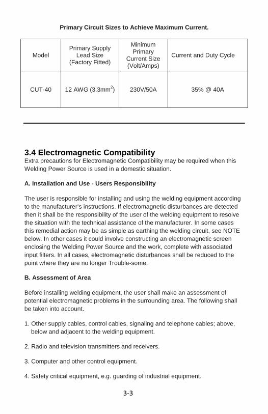
Primary Circuit Sizes to Achieve Maximum Current.
Model Primary Supply
Lead Size (Factory Fitted)
Minimum Primary
Current Size (Volt/Amps)
Current and Duty Cycle
CUT-40 12 AWG (3.3mm2) 230V/50A 35% @ 40A
3.4 Electromagnetic Compatibility Extra precautions for Electromagnetic Compatibility may be required when this Welding Power Source is used in a domestic situation.
A. Installation and Use - Users Responsibility
The user is responsible for installing and using the welding equipment according to the manufacturer’s instructions. If electromagnetic disturbances are detected then it shall be the responsibility of the user of the welding equipment to resolve the situation with the technical assistance of the manufacturer. In some cases this remedial action may be as simple as earthing the welding circuit, see NOTE below. In other cases it could involve constructing an electromagnetic screen enclosing the Welding Power Source and the work, complete with associated input filters. In all cases, electromagnetic disturbances shall be reduced to the point where they are no longer Trouble-some.
B. Assessment of Area
Before installing welding equipment, the user shall make an assessment of potential electromagnetic problems in the surrounding area. The following shall be taken into account.
1. Other supply cables, control cables, signaling and telephone cables; above, below and adjacent to the welding equipment.
2. Radio and television transmitters and receivers.
3. Computer and other control equipment.
4. Safety critical equipment, e.g. guarding of industrial equipment.

3-4
5. The health of people around, e.g. the use of pace-makers and hearing aids.
6. Equipment used for calibration and measurement.
7. The time of day that welding or other activities are to be carried out.
8. The immunity of other equipment in the environment: the user shall ensure that other equipment being used in the environment is compatible: this may require additional protection measures.
The size of the surrounding area to be considered will depend on the structure of the building and other activities that are taking place. The surrounding area may extend beyond the boundaries of the premises.
C. Methods of Reducing Electromagnetic Emissions
1. Mains Supply
Arc cutting equipment should be connected to the mains supply according to the manufacturer’s recommendations. If interference occurs, it may be necessary to take additional precautions such as filtering of the mains supply. Consideration should be given to shielding the supply cable of permanently installed welding equipment in metallic conduit or equivalent. Shielding should be electrically continuous throughout its length. The shielding should be connected to the Cutting Power Source so that good electrical contact is maintained between the conduit and the Cutting Power Source enclosure.
2. Maintenance of Cutting Equipment
The arc cutting equipment should be routinely maintained according to the manufacturer’s recommendations. All access and service doors and covers should be closed and properly fastened when the cutting equipment is in operation. The cutting equipment should not be modified in any way except for those changes and adjustments covered in the manufacturer’s instructions. In particular, the spark gaps of arc striking and stabilizing devices should be adjusted and maintained according to the manufacturer’s recommendation.
3. Torch and Ground Cables
The torch and ground cables should be kept as short as possible and should be positioned close together, running at or close to the floor level.
3-5
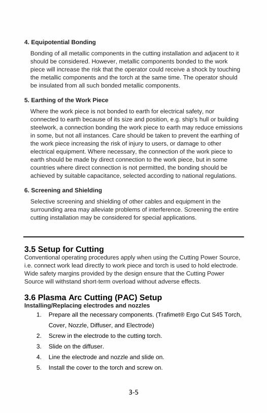
4. Equipotential Bonding
Bonding of all metallic components in the cutting installation and adjacent to it should be considered. However, metallic components bonded to the work piece will increase the risk that the operator could receive a shock by touching the metallic components and the torch at the same time. The operator should be insulated from all such bonded metallic components.
5. Earthing of the Work Piece
Where the work piece is not bonded to earth for electrical safety, nor connected to earth because of its size and position, e.g. ship’s hull or building steelwork, a connection bonding the work piece to earth may reduce emissions in some, but not all instances. Care should be taken to prevent the earthing of the work piece increasing the risk of injury to users, or damage to other electrical equipment. Where necessary, the connection of the work piece to earth should be made by direct connection to the work piece, but in some countries where direct connection is not permitted, the bonding should be achieved by suitable capacitance, selected according to national regulations.
6. Screening and Shielding
Selective screening and shielding of other cables and equipment in the surrounding area may alleviate problems of interference. Screening the entire cutting installation may be considered for special applications.
3.5 Setup for Cutting Conventional operating procedures apply when using the Cutting Power Source, i.e. connect work lead directly to work piece and torch is used to hold electrode. Wide safety margins provided by the design ensure that the Cutting Power Source will withstand short-term overload without adverse effects.
3.6 Plasma Arc Cutting (PAC) Setup Installing/Replacing electrodes and nozzles
1. Prepare all the necessary components. (Trafimet® Ergo Cut S45 Torch, Cover, Nozzle, Diffuser, and Electrode)
2. Screw in the electrode to the cutting torch. 3. Slide on the diffuser. 4. Line the electrode and nozzle and slide on. 5. Install the cover to the torch and screw on.

3-6
Installing the Torch
1. Connect the red cable with the red terminal on the front side of the plasma cutter.
2. Connect the torch control cable to the black, round, 3-pronged connector on the front of the plasma cutter. Be certain to properly align the notch in the connector with the grove in the plug.
3. Connect the torch to the negative (-) receptacle. 4. The right connection 5. Connect the grounding cable to the positive (+) receptacle.
Air Compressor Connection NOTE: The CUT-40 requires 4.5 cfm @60 psi air pressure to operate.
1. Connect the air compressor to the quick connect on the back panel. (Install with Teflon tape to prevent leaking)
electrode diffuser
nozzle cover

4-1
SECTION 4:
OPERATION 4.1 General Operation Conventional operating procedures apply when using the Cutting Power Source, i.e. connect work lead directly to work piece and torch is used to hold electrode. Wide safety margins provided by the design ensure that the Cutting Power Source will withstand short-term overload without adverse effects. 4.2 Front Panel/Controls Familiarize yourself with the location and purpose of the controls on this unit before attempting to operate.
A) Gas Pressure Display
The built-in gas display is used for reading the output gas pressure when cutting.
B) Power Indicator Light This light will turn on when the input power cord is plugged into the power supply and the power switch on the back of the plasma cutter is in the "ON" position.
C) Work Indicator When cutting, this light is on to show the unit is on working mode.
D) Protection Indicator Light When the unit is in thermal overload, is over voltage or lacking voltage, the indicator will be on and the machine will stop working. When the unit
A) F)
C) B)
E) D)

4-2
is cooled down and voltage stabilizes, the unit will return to work automatically.
E) Low Air Pressure Indicator Light This light will be on when the gas flow is low.
F) Cutting Current Adjustor Variable adjust the output cutting current. The higher output matches the thicker metal. The maximum cutting thickness is up to 3/8 ″ for this unit. Please note that the maximum cutting thickness varies depending on the material type you are cutting. See the following table for reference. Material Maximum Cutting Thickness Carbon Steel 3/8”
Aluminum 1/4” Stainless Steel 1/4” Copper 1/8”
4.3 Back Panel/Power Switch Familiarize yourself with the location of the “Back Panel” Power Switch before attempting to operate. The “Back Panel” Power Switch controls the Mains Supply Voltage to the Power Source.
4.3 Operating Instructions
• Check the plasma cutter to see if it has been connected correctly and is in good working condition as described in within this manual and that it complies with safe operation requirements.
• Switch on the power supply switch of the cutter to observe if the operation is normal. If it is normal, the fan should start up and the Power Supply Indicator Light should be on. If there is no compressed air or the air pressure is low the Low Pressure Indicator Light will be on.
ON
OFF

4-3
• Adjust the air supply valve until the air pressure is up to the cutting torch
requirement. (Lowest pressure should be no less than 50PSI), the Low Pressure Indicator Light will not be lit up in those conditions.
• Adjust the air flow to be sure it is consistent. • Pull the torch trigger. The cutting operation begins after the cutting
plasma pilot arc is made. Metal Sheet Cutting • Put the torch’s nozzle at the start of the work piece. Turn on the torch
switch to ignite the plasma pilot. After the work piece is cut thorough, move the torch along the cutting direction uniformly. The cutting speed is determined by watching to see if the cutting goes all the way through. If the speed is too fast, the work piece won’t be cut thorough, or if too slow, the cut quality would be affected, excessive warping may occur, or the arc could stop.
• When you’ve completed the cutting process, turn off the torch; the plasma pilot arc will stop.
Metal Mesh Cutting • Fix the work piece and connect the earth cable with the work piece. • Put the cutting nozzle onto the work piece, lift torch up slightly from the
work piece and turn on the switch to cut. Notice while cutting • Unnecessary igniting of the pilot arc in the air will reduce the life-span of
the torch’s electrode and nozzle. • It is best to start cutting at the edge of the work piece, unless you are
piercing the work piece. • Keep a space between the nozzle and the work piece. Pressing the
nozzle on the work piece could cause the nozzle to stick, reducing the smoothness of the cutting action creating an undesirable result.
• Keep the torch’s nozzle vertical against the work piece, and watch to be sure the arc is moving along the cutting line.
• For thin materials reduce the amperage setting to get the best cutting quality, reduce excessive warping and to extend the life of the electrode and nozzle.
• Do not rapidly switch the torch trigger on and off; this will damage the pilot arc system and work piece.
• The plasma cutter’s working air pressure range is 40-90psi. Notice: the internal pressure switch will shut off when the air pressure falls below 50psi. The switch only works when the pressure rises to 50psi or above.
• Every 4-8 hours, check the air filter on your air supply and remove excess moisture. Too much moisture in the cutter or torch may lead to operational trouble.
Safety Requirements • Never allow the torch to be aimed at any part of a body. • Make sure to wear protective glasses and gloves while operating. • Work only in well-ventilated areas. If necessary, use exhaust/ventilation
fans to keep fumes or emissions away from the breathing zone. • Do not touch the work piece while cutting. • Do not cut a pipes, containers, or other materials that contain, or have
ever contained, flammable or explosive materials.

4-4
• Do not work underwater or in wet/moist environments. • Do not bend the torch cable sharply; this may damage the air hose. • Nobody other than the operator should be allowed to access the
working area. • Always turn off the power supply prior to repairing or moving the
machine. • Always turn off the power supply prior to repairing or installing any spare
parts (e.g., torch, electrode, nozzle, ground clamp, etc.). • Never allow a person with a cardiac pacemaker close to the working
area without the permission of a doctor. • The magnetic field produced by plasma cutters during operation can
disrupt pacemakers and similar devices. • Do not allow the ground cable to be pinched or damaged. If damaged,
replace immediately. • Never clean the slag off the torch head by hitting it against a hard
object.

4-1A
SECCIÓN 4: OPERACIÓN 4.1 Funcionamiento General Los procedimientos convencionales de servicio son aplicables cuando se utiliza
el corte Fuente de energía, el trabajo de conectar es decir, conducen directamente a la pieza de trabajo y la antorcha se utiliza para mantener los electrodos. Amplio margen de seguridad proporcionado por el diseño de asegurar que el corte de la fuente de alimentación puede soportar la sobrecarga a corto plazo, sin efectos adversos.
4.2 del panel frontal / controles Familiarícese con la ubicación y finalidad de los controles en esta unidad antes de intentar operar.
A) Mostrar la presión de gas
La pantalla integrada de gas se utiliza para la lectura de la presión del gas de salida durante el corte.
B) La luz indicadora de energía Esta luz se enciende cuando el cable de potencia de entrada está conectada a la fuente de alimentación y el interruptor de encendido en la parte posterior de la cortadora de plasma está en la posición "ON".
C) Trabajo Indicador Al cortar, esta luz está encendida para mostrar la unidad está en modo de trabajo.
D) Luz Indicador de Protección Cuando la unidad está en la sobrecarga térmica, es de más tensión de voltaje o falta, el indicador estará encendido y la máquina dejará de
B) F)
C) B)
E) D)

4-2A
funcionar. Cuando la unidad se haya enfriado y estabiliza el voltaje, la unidad volverá a funcionar automáticamente.
E) de baja presión de aire luz indicadora Esta luz se enciende cuando el flujo de gas es baja.
F) Ajustador de corte de corriente Variable ajustar la salida de corriente de corte. La mayor producción coincide con el metal más grueso. El espesor de corte máximo es de hasta 3 / 8 "para esta unidad. Tenga en cuenta que el espesor máximo de corte varía según el tipo de material que está cortando. Consulte la tabla siguiente como referencia. Material Maximum Cutting Thickness Carbon Steel 3/8” Aluminum 1/4” Stainless Steel 1/4” Copper 1/8”
4.3 Panel trasero / interruptor de alimentación Familiarícese con la ubicación de la "Panel trasero" interruptor de alimentación antes de intentar operar. El "panel posterior" interruptor de encendido controla la tensión de red a la fuente de alimentación.
4.3 Instrucciones de uso
• Verifica en el cortador de plasma para ver si se ha conectado correctamente y está en buenas condiciones de trabajo como se describe en el interior de este manual y que cumple con los requisitos de operación segura.
• Encender el interruptor de alimentación de la cortadora para observar si el funcionamiento es normal. Si es normal, el ventilador debe poner en marcha y la fuente de alimentación Indicador de luz debe estar encendida. Si no hay aire comprimido o la presión del aire es baja, la presión baja luz indicadora se encenderá.
• Ajuste la válvula de suministro de aire hasta la presión de aire depende de la exigencia de la antorcha de corte. (La presión más baja no debe
ON
OFF

4-3A
ser inferior a 50 psi), la luz indicadora de baja presión no se encenderá en esas condiciones.
• Ajuste el flujo de aire para asegurarse de que es coherente. • Tire del gatillo de la antorcha. La operación de corte comienza después
de que el arco de plasma piloto de corte que se haga. De corte de chapa • Coloque la boquilla de la antorcha al comienzo de la pieza de trabajo.
Encienda el interruptor de la antorcha para encender el piloto de plasma. Después de la pieza es cortada a fondo, mover la antorcha a lo largo de la dirección de corte uniforme. La velocidad de corte se determina observando para ver si el corte va todo el camino. Si la velocidad es demasiado rápida, la pieza de trabajo no se cortará a fondo, o si es demasiado lento, la calidad de corte se vería afectada, pues se pueden producir deformaciones excesivas, o el arco de paro si.
• Cuando haya completado el proceso de corte, apague la antorcha, el arco piloto de plasma se detendrá.
De malla metálica de corte • Fijar la pieza de trabajo y conectar el cable de tierra con la pieza de
trabajo. • Coloque la boquilla de corte en la pieza de trabajo, levantar la antorcha
ligeramente superior al de la pieza de trabajo y encienda el interruptor para cortar.
Aviso durante el corte • innecesarios encendido del arco piloto en el aire se reduce la vida útil
de los electrodos de la antorcha y la boquilla. • Lo mejor es empezar a cortar en el borde de la pieza de trabajo, a
menos que esté atravesando la pieza de trabajo. • Deje un espacio entre la boquilla y la pieza de trabajo. Al presionar la
boquilla de la pieza de trabajo puede causar la boquilla de palo, la reducción de la suavidad de la acción de corte la creación de un resultado indeseable.
• Mantenga la boquilla de la antorcha vertical contra la pieza de trabajo, y mirar para asegurarse que el arco se mueve a lo largo de la línea de corte.
• Para materiales delgados reducir el amperaje de configuración para obtener la mejor calidad de corte, reducir la deformación excesiva y para alargar la vida del electrodo y la boquilla.
• No cambiar rápidamente el pulsador de la antorcha y fuera ya que podría dañarse el sistema de arco piloto y la pieza de trabajo.
• El cortador del plasma de la gama de trabajo de presión de aire es de 40-90psi. Aviso: el interruptor de la presión interna se apaga cuando la presión del aire cae por debajo de 50 psi. El interruptor sólo funciona cuando la presión se eleva a 50 psi o más.
• Cada 4-8 horas, visita el filtro de aire en el suministro de aire y eliminar el exceso de humedad. Demasiada humedad en la corte o de la antorcha puede conducir a problemas operacionales.
Requisitos de seguridad • Nunca permita que la antorcha a dirigirse a cualquier parte del cuerpo. • Asegúrese de usar gafas protectoras y guantes durante la operación.

4-4A
• Trabajar sólo en áreas bien ventiladas. Si es necesario, el uso de
escape de aire y ventiladores para mantener los humos o las emisiones fuera de la zona de respiración.
• No toque la pieza de trabajo durante el corte. • No cortar tuberías, contenedores u otros materiales que contienen, o
alguna vez contenidos, materiales inflamables o explosivos. • No trabaje bajo el agua o en mojado / ambientes húmedos. • No doble el cable de la antorcha bruscamente, lo que puede dañar la
manguera de aire. • Nadie que no sea el creador debe permitir acceder a la zona de trabajo. • Siempre apague la fuente de alimentación antes de reparar o desplazar
la máquina. • Siempre apague la fuente de alimentación antes de la reparación o
instalación de piezas de repuesto (por ejemplo, la antorcha, el electrodo, boquilla, abrazadera de tierra, etc.)
• Nunca permita que una persona con un marcapasos cardíaco cerca de la zona de trabajo sin la autorización de un médico.
• El campo magnético producido por cortadoras de plasma durante la operación puede afectar los marcapasos y otros dispositivos similares.
• No permita que el cable de tierra a ser oprimidos o dañados. Si está dañado, cámbielo inmediatamente.
• Nunca limpie la escoria de la cabeza del soplete golpeándola contra un objeto duro.

5-1
SECTION 5: MAINTENANCE AND TROUBLESHOOTING 5.1 Maintenance The only routine maintenance required is a thorough cleaning and inspection, with frequency being dependent upon the usage and the operating environment.
THIS PRODUCT CONTAINS EXREMELY DANGEROUS VOLTAGES. TURN OFF THE POWER SWITCH, UNPLUG THE POWER CABLE FROM THE OUTLET, AND ALLOW AT LEAST 2 MINUTES FOR THE PRIMARY CAPACITORS TO DISCHARGE BEFORE PERFORMING MAINTENANCE OR ATTEMPTING TO OPEN THE ENCLOSURE.
To clean the unit, open the enclosure and use a vacuum cleaner or blow gun to remove any accumulated dirt and dust. Avoid direct contact with electrical boards. Ensure that all fans and exhaust vents are clean and clear.
The unit should also be wiped clean, if necessary; with solvents that are recommended for cleaning electrical appliances.
MAINTENANCE SCHEDULE Maintain more often if used under extremely dusty or severe conditions.
EACH USE: Visual inspection of regulator, pressure, and consumable parts.
WEEKLY: Visual inspection of torch body, consumables, cables, and leads. Replace or repair as needed.
3 MONTHS: Clean exterior of power supply. Clean and tighten weld terminals.
6 MONTHS: Blow out or vacuum and accumulated dust/dirt from the interior.
5.2 Troubleshooting If you are experiencing trouble with your unit, please refer to the following table for assistance. If you are experiencing issues that are not addressed in the following please contact Smarter Tools Customer Service for help in resolving your issue.

5-2
Power Indicator Light is off after turning on the power supply.
1. The light is broken. 2. Fuse is blown. 3. Not 230V Input
Voltage. 4. Power supply switch is
broken. 5. Controlling board or
cutter is damaged.
1. Replace. 2. Replace. 3. Connect the 230V
Input cable. 4. Replace. 5. Examine and repair.
Fan doesn’t work after turning on the power supply.
1. Fan is damaged. 2. Fan’s ground lead is
broken. 3. Fan’s blade is blocked 4. Transformer is
damaged.
1. Replace. 2. Examine and repair. 3. Clean the block. 4. Replace.
Low Pressure Indicator Light is on
1. No input compressed air
2. Air/gas pressure valve is adjusted to 0 or broken.
3. Air/gas pressure circuit is blocked
4. Air/gas pressure valve is damaged
1. Examine and repair. 2. Adjust or replace. 3. Clean the block. 4. Replace.
No Air/gas check function.
1. Air/Gas valve is ruined.
2. Air/Gas circuit is blocked.
3. Air/Gas check switch is ruined
4. Ground lead is broken.
1. Replace. 2. Clean the block. 3. Replace. 4. Examine and repair.

5-3
Can’t cut or no high frequency output.
1. Discharge gap is too big.
2. High pressure mica capacitance damaged.
3. Pilot transformer is damaged.
4. Main controlling board is damaged.
5. Ground lead is broken
1. Adjust to suitable gap. 2. Replace. 3. Replace. 4. Examine and repair. 5. Examine and repair.
No response after turning on the torch switch.
1. Switch and ground-lead are broken.
2. Switch board is broken.
3. Main controlling board is damaged.
4. Transformer is damaged.
5. Ground lead is broken.
1. Examine and repair or replace.
2. Examine and repair or replace.
3. Examine and repair or replace.
4. Replace. 5. Examine and repair.
No response after turning on power supply.
1. Power cord hooked up wrong.
2. Power supply switch is broken.
3. Fuse is damaged. 4. Transformer is broken. 5. Main controlling board
is ruined.
1. Examine and repair. 2. Replace. 3. Replace. 4. Replace. 5. Examine and repair or
replace.
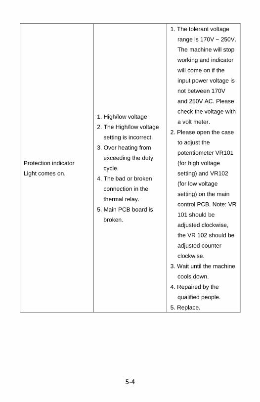
5-4
Protection indicator Light comes on.
1. High/low voltage 2. The High/low voltage
setting is incorrect. 3. Over heating from
exceeding the duty cycle.
4. The bad or broken connection in the thermal relay.
5. Main PCB board is broken.
1. The tolerant voltage range is 170V ~ 250V. The machine will stop working and indicator will come on if the input power voltage is not between 170V and 250V AC. Please check the voltage with a volt meter.
2. Please open the case to adjust the potentiometer VR101 (for high voltage setting) and VR102 (for low voltage setting) on the main control PCB. Note: VR 101 should be adjusted clockwise, the VR 102 should be adjusted counter clockwise.
3. Wait until the machine cools down.
4. Repaired by the qualified people.
5. Replace.

5-5
5.3 System Schematic

5-6
5.4 Parts List
1 Handle 2 Shell 3 Control Transformer
4 Control Board 5 Relay 6 Potentiometer
7 Cement Resistance 8 Middle Separate Board 9 Coil
10 Bridge Rectifier Radiator
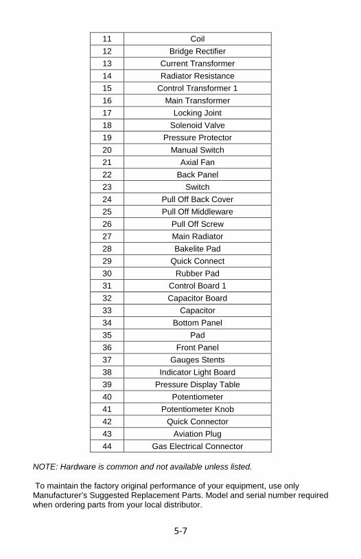
5-7
11 Coil 12 Bridge Rectifier 13 Current Transformer 14 Radiator Resistance 15 Control Transformer 1 16 Main Transformer 17 Locking Joint 18 Solenoid Valve 19 Pressure Protector 20 Manual Switch 21 Axial Fan 22 Back Panel 23 Switch 24 Pull Off Back Cover 25 Pull Off Middleware 26 Pull Off Screw 27 Main Radiator 28 Bakelite Pad 29 Quick Connect 30 Rubber Pad 31 Control Board 1 32 Capacitor Board 33 Capacitor 34 Bottom Panel 35 Pad 36 Front Panel 37 Gauges Stents 38 Indicator Light Board 39 Pressure Display Table 40 Potentiometer 41 Potentiometer Knob 42 Quick Connector 43 Aviation Plug 44 Gas Electrical Connector
NOTE: Hardware is common and not available unless listed. To maintain the factory original performance of your equipment, use only Manufacturer’s Suggested Replacement Parts. Model and serial number required when ordering parts from your local distributor.

5-1A
SECCIÓN 5: MANTENIMIENTO Y RESOLUCIÓN DE PROBLEMAS 5.1 Mantenimiento El único mantenimiento de rutina a una limpieza a fondo y de inspección, con la frecuencia que depende del uso y el entorno operativo.
ESTE PRODUCTO CONTIENE TENSIONES exremely PELIGROSO. Apague el interruptor de alimentación, desenchufe el cable de alimentación de la toma, y por lo menos 2 MINUTOS PARA LA DESCARGA DE CONDENSADORES PRIMARIA PARA ANTES DE MANTENIMIENTO DE REALIZAR O INTENTAR ABRIR LA CAJA.
Para limpiar la unidad, abra la caja y el uso de una aspiradora o con pistola de aire comprimido para eliminar la suciedad y el polvo acumulado. Evite el contacto directo con los tableros eléctricos. Asegúrese de que todos los fans y orificio de salida se limpia y clara. La unidad también se debe limpiar, si es necesario, con los solventes que se recomiendan para la limpieza de los aparatos eléctricos.
PROGRAMA DE MANTENIMIENTO Mantener con más frecuencia si se utiliza bajo condiciones de mucho polvo o grave. CADA USO: La inspección visual del regulador, la presión y piezas de desgaste. SEMANA: La inspección visual del cuerpo de la antorcha, consumibles, cables y conductores. Reemplazar o reparar según sea necesario. 3 MESES: Limpie el exterior de la fuente de alimentación. Limpiar y apretar las terminales de soldadura. 6 MESES: a golpe o el vacío y la acumulación de polvo o suciedad del interior.
5.2 Solución de problemas Si usted está experimentando problemas con su unidad, por favor consulte la tabla siguiente para obtener ayuda. Si usted está experimentando problemas que no se abordan en las siguientes póngase en contacto con Smarter Tools Servicio al cliente para ayudar a resolver el problema.
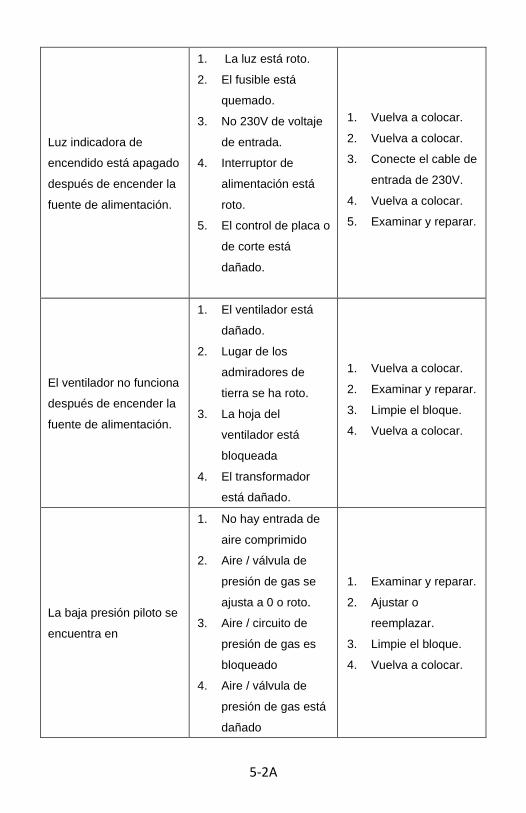
5-2A
Luz indicadora de encendido está apagado después de encender la fuente de alimentación.
1. La luz está roto. 2. El fusible está
quemado. 3. No 230V de voltaje
de entrada. 4. Interruptor de
alimentación está roto.
5. El control de placa o de corte está dañado.
1. Vuelva a colocar. 2. Vuelva a colocar. 3. Conecte el cable de
entrada de 230V. 4. Vuelva a colocar. 5. Examinar y reparar.
El ventilador no funciona después de encender la fuente de alimentación.
1. El ventilador está dañado.
2. Lugar de los admiradores de tierra se ha roto.
3. La hoja del ventilador está bloqueada
4. El transformador está dañado.
1. Vuelva a colocar. 2. Examinar y reparar. 3. Limpie el bloque. 4. Vuelva a colocar.
La baja presión piloto se encuentra en
1. No hay entrada de aire comprimido
2. Aire / válvula de presión de gas se ajusta a 0 o roto.
3. Aire / circuito de presión de gas es bloqueado
4. Aire / válvula de presión de gas está dañado
1. Examinar y reparar. 2. Ajustar o
reemplazar. 3. Limpie el bloque. 4. Vuelva a colocar.

5-3A
No Air / función de verificación de gas.
1. Aire / válvula de gas está en ruinas.
2. Aire / gas de circuito está bloqueado.
3. Aire / interruptor de control de gas está en ruinas
4. Cable de tierra se ha roto.
1. Vuelva a colocar. 2. Limpie el bloque. 3. Vuelva a colocar. 4. Examinar y reparar.
No se puede cortar o no hay salida de alta frecuencia.
1. Espacio de descarga es demasiado grande.
2. La presión alta de la capacitancia de mica dañado.
3. Transformador piloto está dañado.
4. Placa base de control está dañada.
5. Cable de tierra se rompe
1. Ajuste a distancia adecuada.
2. Vuelva a colocar. 3. Vuelva a colocar. 4. Examinar y reparar.
5. Examinar y reparar.

5-4A
No hay respuesta después de encender el interruptor de la antorcha.
1. Interruptor y cable de tierra-se rompen.
2. Cuadro de mandos está rota.
3. Placa base de control está dañada.
4. El transformador está dañado.
5. Cable de tierra se ha roto.
1. Examinar y reparar o reemplazar.
2. Examinar y reparar o reemplazar.
3. Examinar y reparar o reemplazar.
4. Vuelva a colocar. 5. Examinar y reparar.
No hay respuesta después de encender la fuente de alimentación.
1. El cable de alimentación conectado mal.
2. Interruptor de alimentación está roto.
3. El fusible está dañado.
4. El transformador está roto.
5. Placa base de control está en ruinas.
1. Examinar y reparar. 2. Vuelva a colocar. 3. Vuelva a colocar. 4. Vuelva a colocar. 5. Examinar y reparar
o reemplazar.

5-5A
Protección indicador La luz se enciende.
1. Alta y baja tensión 2. El Alto /
configuración de baja tensión es incorrecta.
3. Más de la calefacción a no rebasar el ciclo de trabajo.
4. La mala conexión o roto en el relé térmico.
5. Principal placa PCB está roto.
1. El rango de voltaje de 170V es tolerante ~ 250V. La máquina dejará de funcionar y el indicador se encenderá si el voltaje de entrada no está entre 170V y 250V AC. Por favor, compruebe el voltaje con un voltímetro.
2. Por favor, abra la caja para ajustar el potenciómetro VR101 (para el ajuste de alta tensión) y VR102 (por valor de voltaje bajo) en el control de PCB principal. Nota: VR 101 se debe ajustar las agujas del reloj, el VR 102 debe ser ajustado hacia la izquierda.
3. Espere hasta que la máquina se enfríe.
4. Reparado por el personal calificado.
5. Vuelva a colocar.

5-6A
5.3 Esquema del sistema
5.4

5-7A
5.4 Lista de piezas
1 Handle
2 Shell 3 Control Transformer 4 Control Board 5 Relay 6 Potentiometer
7 Cement Resistance 8 Middle Separate Board 9 Coil
10 Bridge Rectifier Radiator

5-8A
11 Coil 12 Bridge Rectifier 13 Current Transformer 14 Radiator Resistance 15 Control Transformer 1 16 Main Transformer 17 Locking Joint 18 Solenoid Valve 19 Pressure Protector 20 Manual Switch 21 Axial Fan 22 Back Panel 23 Switch 24 Pull Off Back Cover 25 Pull Off Middleware 26 Pull Off Screw 27 Main Radiator 28 Bakelite Pad 29 Quick Connect 30 Rubber Pad 31 Control Board 1 32 Capacitor Board 33 Capacitor 34 Bottom Panel 35 Pad 36 Front Panel 37 Gauges Stents 38 Indicator Light Board 39 Pressure Display Table 40 Potentiometer 41 Potentiometer Knob 42 Quick Connector 43 Aviation Plug 44 Gas Electrical Connector
NOTA: El hardware es común y no están disponibles a menos que figuren. Para mantener el rendimiento original de fábrica de su equipo, utilice sólo el fabricante de piezas de reemplazo sugerida. Modelo y número de serie necesario cuando los pedidos de piezas de su distribuidor loca


![Specificaţii tehnice (F4.1) în coloanele , î, ò, ô]](https://img.dokumen.tips/doc/110x75/623bae143468554f2814f394/specificatii-tehnice-f41-n-coloanele-.jpg)