Embed Size (px)
Citation preview

canadair chsfflencjiBr OPERATING MANUAL
PSP 601A-6
SECTION 13
HYDRAULICS
TABLE OF CONTENTS
Page
GENERAL 1
HYDRAULIC SYSTEM COMPONENTS 1
A. Engine Pumps (2) 1 B. Electric Pumps (4) 1 C. Reservoirs (3) 2 D. Accumulators (3) 2 E. Heat Exchanger 2
LANDING GEAR 2
A. Landing Gear Control Unit 3 B. Landing Gear Control Lever 3
MAIN LANDING GEAR BAY OVERHEAT DETECTION SYSTEM 3
NOSE WHEEL STEERING 4
BRAKES AND ANTI-SKID SYSTEM 4
A. Brakes 4 B. Anti-Skid System 5 C. Parking Brake 5
LIST OF ILLUSTRATIONS
Figure Title Page Number
1 Hydraulic System - Schematic (3 Sheets) 6
2 Hydraulic System Controls and Indicators 9
3 Landing Gear Controls and Indicators 10
4 Main Landing Gear Bay Overheat Warning Lights 11
5 Nose Wheel Steering Controls and Indicators 12
6 Brake and Anti-Skid Controls and Indicators 13
13-CONTENTS Page 1
Aug 14/02

canadair chaJlsnqer OPERATING MANUAL
PSP 601A-6
SECTION 13
HYDRAULICS
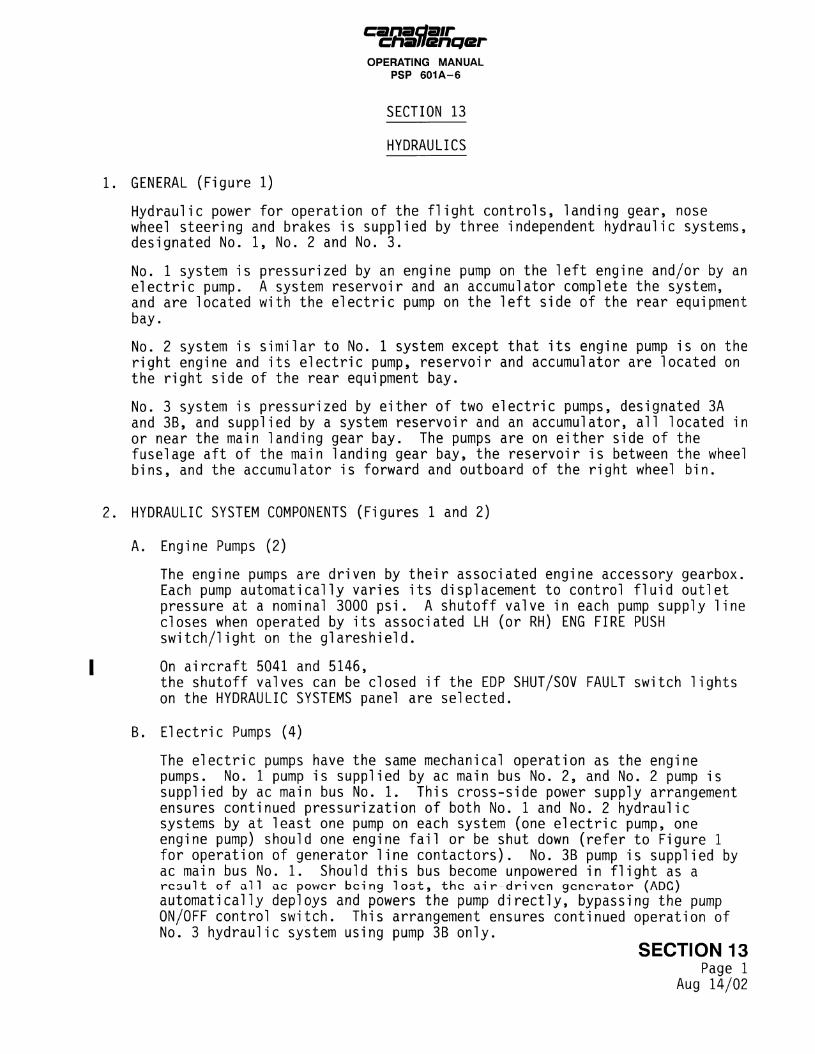
GENERAL (Figure 1)
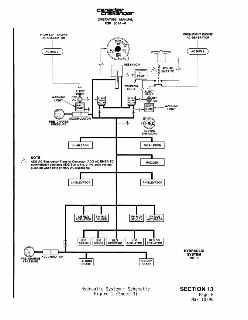
Hydraulic power for operation of the flight controls, landing gear, nose wheel steering and brakes is supplied by three independent hydraulic systems, designated No. 1, No. 2 and No. 3.
No. 1 system is pressurized by an engine pump on the left engine and/or by an electric pump. A system reservoir and an accumulator complete the system, and are located with the electric pump on the left side of the rear equipment bay.
No. 2 system is similar to No. 1 system except that its engine pump is on the right engine and its electric pump, reservoir and accumulator are located on the right side of the rear equipment bay.
No. 3 system is pressurized by either of two electric pumps, designated 3A and 3B, and supplied by a system reservoir and an accumulator, all located in or near the main landing gear bay. The pumps are on either side of the fuselage aft of the main landing gear bay, the reservoir is between the wheel bins, and the accumulator is forward and outboard of the right wheel bin.
HYDRAULIC SYSTEM COMPONENTS (Figures 1 and 2)
A. Engine Pumps (2)
The engine pumps are driven by their associated engine accessory gearbox. Each pump automatically varies its displacement to control fluid outlet pressure at a nominal 3000 psi. A shutoff valve in each pump supply line closes when operated by its associated LH (or RH) ENG FIRE PUSH switch/light on the glareshield.
On aircraft 5041 and 5146, the shutoff valves can be closed if the EDP SHUT/SOV FAULT switch lights on the HYDRAULIC SYSTEMS panel are selected.
B. Electric Pumps (4)
The electric pumps have the same mechanical operation as the engine pumps. No. 1 pump is supplied by ac main bus No. 2, and No. 2 pump is supplied by ac main bus No. 1. This cross-side power supply arrangement ensures continued pressurization of both No. 1 and No. 2 hydraulic systems by at least one pump on each system (one electric pump, one engine pump) should one engine fail or be shut down (refer to Figure 1 for operation of generator line contactors). No. 3B pump is supplied by ac main bus No. 1. Should this bus become unpowered in flight as a r e s u l t o f a l l ac power being l o s t , the a i r d r i v e n g e n e r a t o r (ADC) automatically deploys and powers the pump directly, bypassing the pump ON/OFF control switch. This arrangement ensures continued operation of No. 3 hydraulic system using pump 3B only.
SECTION 13 Page 1
Aug 14/02

canadair chsuiencjBr
OPERATING MANUAL PSP 601A-6
C. Reservoirs (3)
The hydraulic system reservoirs are of the self-pressurizing, bootstrap type. A suction pressure of 55 psi is maintained by associated system pressure acting on a piston within each reservoir. Each reservoir has a direct reading fluid level indicator, a fluid temperature probe and an overflow line connected to an overflow tank.
D. Accumulators (3)
Each piston-type accumulator maintains pressure when rapid increases in demand are made on the associated system. The accumulator pre-charged pressure can be read on a gauge located near the accumulator. Should a double engine failure occur, No. 3 system accumulator would also cater to the flight control requirements until the air-driven generator (ADG) came on line.
E. Heat Exchanger
A ram air heat exchanger, with separate cores for No. 1 and No. 2 systems, is located aft of the rear equipment bay door. Ram air from the dorsal fin inlet cools the cores in flight. An automatic, temperature-controlled, electric blower cools the cores if an overheat condition occurs. The No. 3 system is cooled by its hydraulic lines running through the fuel in the wing tanks.
3. LANDING GEAR (Figure 3)
The main landing gear retracts inward into a recess in the wing and centre fuselage, and the nose landing gear retracts forward beneath the flight compartment. Normal extension and retraction is electrically controlled and hydraulically operated. Hydraulic pressure for normal landing gear operation is supplied by No. 3 hydraulic system.
For emergency landing gear operation, the gear may be extended by pulling the landing gear manual release T-handle in the flight compartment. The handle mechanically releases the landing gear uplocks and dumps hydraulic pressure, allowing the gear to free-fall. The gear is assisted by a combination of airflow and spring pressure on the nose gear, and by a down-lock assist actuator, supplied by No. 2 hydraulic system, on the main gear.
The landing gear control lever is positioned on the right side of the centre instrument panel. Landing gear position indications are given by three green lights above the landing gear selector and flashing red lights in the landing gear handle. An aural warning is also provided to warn of unsafe gear configuration for the flight conditions.
SECTION 13 Page 2
Apr 02/87
ctianencjer OPERATING MANUAL
PSP 601A-6
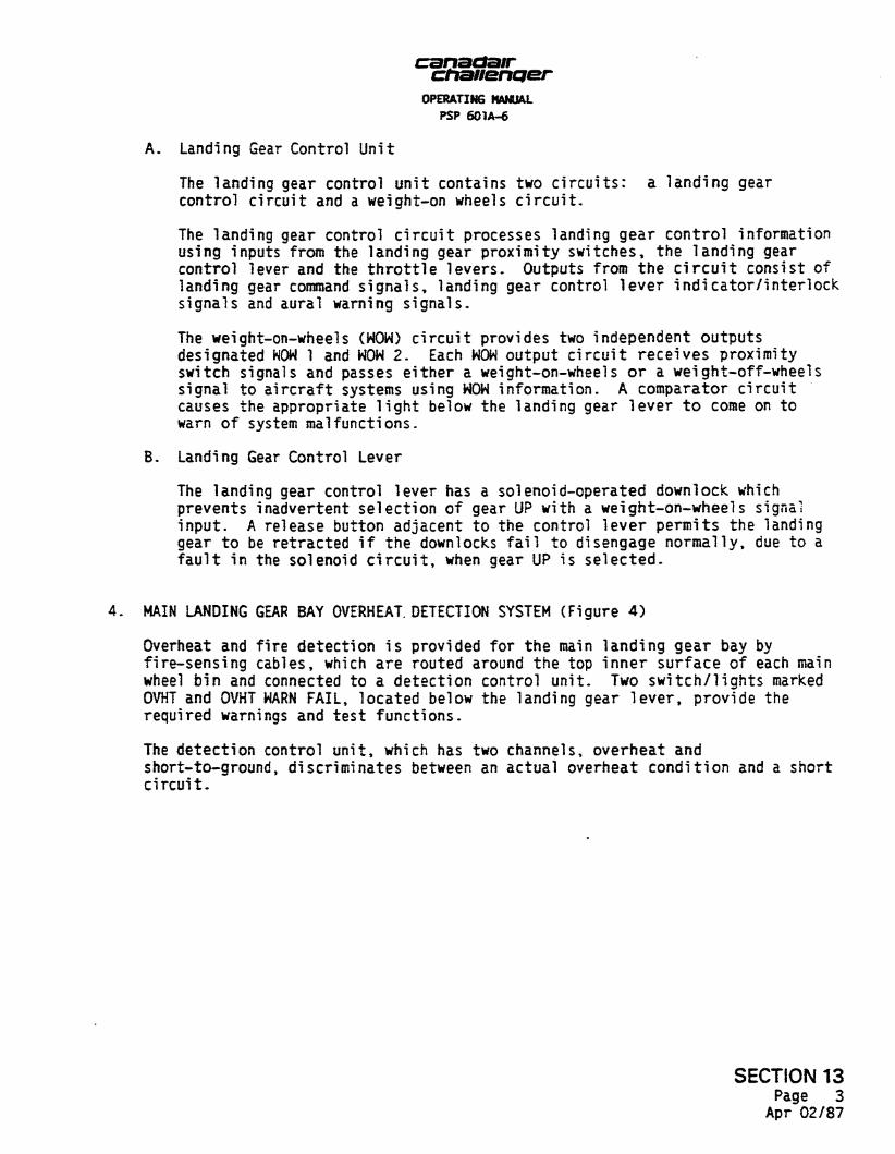
A, Landing Gear Control Unit
The landing gear control unit contains two circuits: a landing gear control circuit and a weight-on wheels circuit,
The landing gear control circuit processes landing gear control information using inputs from the landing gear proximity switches, the landing gear control lever and the throttle levers. Outputs from the circuit consist of landing gear command signals* landing gear control lever indicator/interlock signals and aural warning signals.
The weight-on-wheels (WOW) circuit provides two independent outputs designated WOW 1 and WOW 2. Each WOW output circuit receives proximity switch signals and passes either a weight-on-wheels or a weight-off-wheels signal to aircraft systems using WOW information. A comparator circuit causes the appropriate light below the landing gear lever to come on to warn of system malfunctions.
B. Landing Gear Control Lever
The landing gear control lever has a solenoid-operated downlock which prevents inadvertent selection of gear UP with a weight-on-wheels signal input. A release button adjacent to the control lever permits the landing gear to be retracted if the downlocks fail to disengage normally, due to a fault in the solenoid circuit, when gear UP is selected.
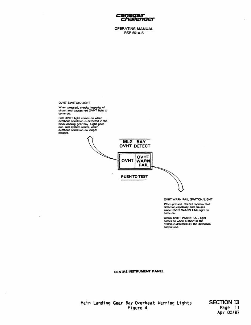
4. MAIN LANDING GEAR BAY OVERHEAT DETECTION SYSTEM (Figure 4)
Overheat and fire detection is provided for the main landing gear bay by fire-sensing cables, which are routed around the top inner surface of each main wheel bin and connected to a detection control unit. Two switch/lights marked OVHT and OVHT WARN FAIL, located below the landing gear lever, provide the required warnings and test functions.
The detection control unit, which has two channels, overheat and short-to-ground, discriminates between an actual overheat condition and a short circuit.
SECTION 13 Page 3 Apr 02/87
OPERATING MANUAL PSP 601A-6
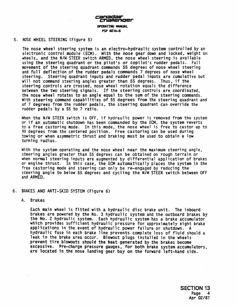
NOSE WHEEL STEERING (Figure 5)
The nose wheel steering system is an electro-hydraulic system controlled by an electronic control module (ECM). With the nose gear down and locked, weight on wheels, and the N/W STEER switch ARMED, the nose wheel steering is available using the steering quadrant or the pilot's or copilot's rudder pedals. Full movement of the steering quadrant commands 55 degrees of nose wheel steering and full deflection of the rudder pedals commands 7 degrees of nose wheel steering. Steering quadrant inputs and rudder pedal inputs are cumulative but will not command steering angles greater than 55 degrees. Thus, i f the steering controls are crossed, nose wheel rotation equals the difference between the two steering signals. If the steering controls are coordinated, the nose wheel rotates to an angle equal to the sum of the steering commands. With steering command capabilities of 55 degrees from the steering quadrant and of 7 degrees from the rudder pedals, the steering quadrant can override the rudder pedals by a 55 to 7 ratio.
When the N/W STEER switch is OFF, i f hydraulic power is removed from the system or i f an automatic shutdown has been commanded by the ECM, the system reverts to a free castoring mode. In this mode, the nose wheel is free to castor up to 99 degrees from the centered position. Free castoring can be used during towing or when asymmetric thrust and braking must be used to obtain a low turning radius.
With the system operating and the nose wheel near the maximum steering angle, steering angles greater than 55 degrees can be obtained on rough terrain or when normal steering inputs are augmented by differential application of brakes or engine thrust. In this case, the ECM automatically places the system in the free castoring mode and steering can only be re-engaged by reducing the steering angle to below 55 degrees and cycling the N/W STEER switch between OFF and ARMED.
BRAKES AND ANTI-SKID SYSTEM (Figure 6)
A. Brakes
Each main wheel is fitted with a hydraulic disc brake unit. The inboard brakes are powered by the No. 3 hydraulic system and the outboard brakes by the No- 2 hydraulic system. Each hydraulic system has a brake accumulator which provides sufficient hydraulic pressure for approximately eight brake applications in the event of hydraulic power failure or shutdown. A hydraulic fuse in each brake line prevents complete loss of fluid should a leak in the brake area occur. Blowout plugs installed in the wheels prevent tire blowouts should the heat generated by the brakes become excessive- Pre-charge pressure gauges, for both brake system accumulators, are located in the nose landing gear bay on the forward left-hand side.
SECTION 13 Page 4
Apr 02/87
canadair chauenQer OPERATING MANUAL
PSP 601A-6
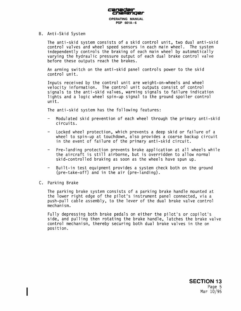
Anti-Skid System
The anti-skid system consists of a skid control unit, two dual anti-skid control valves and wheel speed sensors in each main wheel. The system independently controls the braking of each main wheel by automatically varying the hydraulic pressure output of each dual brake control valve before these outputs reach the brakes.
An arming switch on the anti-skid panel controls power to the skid control unit.
Inputs received by the control unit are weight-on-wheels and wheel velocity information. The control unit outputs consist of control signals to the anti-skid valves, warning signals to failure indication lights and a logic wheel spin-up signal to the ground spoiler control unit.
The anti-skid system has the following features:
Modulated skid prevention of each wheel through the primary anti-skid circuits.
Locked wheel protection, which prevents a deep skid or failure of a wheel to spin-up at touchdown, also provides a coarse backup circuit in the event of failure of the primary anti-skid circuit.
Pre-landing protection prevents brake application at all wheels while the aircraft is still airborne, but is overridden to allow normal skid-controlled braking as soon as the wheels have spun up.
Built-in test equipment provides a system check both on the ground (pre-take-off) and in the air (pre-landing).
Parking Brake
The parking brake system consists of a parking brake handle mounted at the lower right edge of the pilot's instrument panel connected, via a push-pull cable assembly, to the lever of the dual brake valve control mechanism.
Fully depressing both brake pedals on either the pilot's or copilot's side, and pulling then rotating the brake handle, latches the brake valve control mechanism, thereby securing both dual brake valves in the on position.
SECTION 13 Page 5
Mar 10/95

chzfliencjer OPERATING MANUAL
PSP 601A-6
FROM LEFT ENGINE AC GENERATOR
SWITCH/ LIGHT
SHUT
SOV FAULT
EFFECTIVITY: A/C5041 AND 5146 \
SWITCH/ LIGHT
c AC BUS 2
LH ENG FIRE PUSH
RESERVOIR WARNING LIGHT
-Ar HI TEMP
ELECT A * PUMP / | \ K GLC 2
O F F / ^ 0 N ^ WARNING
LIGHT
j
NOTE
A Generator Line Contactor 2 (GLC 2); only energized (contact made) when right engine generator is powering AC Bus 2 or when a weight-on-wheels signal is present.
HYDRAULIC SYSTEM
NO. 1
Hydraulic System - Schematic Figure 1 (Sheet 1)
SECTION 13 Page 6
Aug 14/02

canadair chauenqer OPERATING MANUAL
PSP 601A-6
FROM RIGHT ENGINE AC GENERATOR
SWITCH/ LIGHT
Generator Line Contactor 1 (GLC 1); only energized (contact made) when left engine generator is powering AC Bus 1 Or when a weight-on-wheels signal is present.
PRE-CHARGE PRESSURE
HYDRAULIC SYSTEM
NO. 2
Hydraulic System - Schematic S E C T I O N 13 Figure 1 (Sheet 2) page 7
Aug 14/02
_ _ _ j a i r chauBnQer OPERATING MANUAL
PSP 601A-6
FROM LEFT ENGINE AC GENERATOR
FROM RIGHT ENGINE AC GENERATOR
A NOTE ADG AC Emergency Transfer Contactor (ADG AC EMER TC) automatically connects ADG Bus to No. 3 hydraulic system pump 3B when both primary AC Busses fail.
LH ELEVATOR
m LHMLG
ACTUATOR LHMLG UPLOCK
i n
NLG UPLCK
NLG DNLCK
RUDDER
RH ELEVATOR
nz\ RHMLG UPLOCK
RHMLG ACTUATOR
NLG STEERING
LIZI NLG
ACTUATOR NLGDR
ACTUATOR
PRE-CHARGE PRESSURE
ACCUMULATOR
LH INBD BRAKE
RH INBD BRAKE
HYDRAULIC SYSTEM
NO. 3
Hydraulic System - Schematic SECTION 13 Figure 1 (Sheet 3) Page 8
Mar 10/95

fUc chanenper OPERATING MANUAL
PSP 6 0 1 A - 6
5 HYDRAULIC SYSTEMS 2 HI TEMP HI TEMP HI TEMP
ELECT PUMP
L. ENG PUMP
ELECT PUMP
ELECT PUMP
R. ENGI PUMP
ELECT PUMP
EDP SHUT/SOV FAULT SWITCH/LIGHT
White SHUT light comet on whenever engine driven pump shutoff valve it in doted position.
Amber SOV FAULT light comet on to indicate fault in engine driven pump control circuit.
HI TEMP
•EPP
ELECT " ™ PUMP -
L. ENG PUMP
© EFFECTIVITY : A/C 5041 AND 5146
HIGH TEMPERATURE WARNING LIGHT
Light comes on to indicate that hydraulic fluid temperature has exceeded upper limit.
AC ELECTRIC PUMP LOW PRESSURE WARNING LIGHT
Warning light comes on at 1800 psi decreasing pump discharge pressure and goes out at 2300 psi increasing pump discharge pressure. Warning light is armed when AC electric pump control switch is set to ON and/or wing flaps are extended.
ELECT I I L. ENG PUMP I PUMP
RESERVOIR QUANTITY INDICATOR
Gauge indicates the hydraulic fluid quantity in the system reservoir. Normal quantity, with the system operating, is 40% to 80% full (green band). Gauge indicates 0% when electric power is removed.
HYDRAULIC SYSTEM PRESSURE INDICATOR
Gauge indicates hydraulic pressure in the system. Normal operating pressure is 3000 psi ± 150 psi. Gauge indicates 0 psi when electrical power is removed.
AC ELECTRIC PUMP ON-OFF SWITCH
Switch provides control of AC pump.
ENGINE DRIVEN PUMP LOW PRESSURE WARNING LIGHT
Warning light comes on at 1800 psi decreasing pump discharge pressure and goes out at 2300 psi increasing pump discharge pressure.
Hydraulic System Controls and Indicators SECTION 13 Figure 2 Page 9
Aug 14/02

, _ ™ - j a i r chaJlenqer OPERATING MANUAL
PSP 601A-6
LANDING GEAR SAFE LIGHTS
NOSE, LEFT and RIGHT green lights come on when respective landing gear legs are down and locked.
LANDING GEAR HANDLE
Two-position handle. Controls landing gear hydraulic operation.
UP - Pulling handle out then up retracts landing gear, applies in-flight brakes and closes nose wheel doors.
DN - Pulling handle out then down opens nose wheel doors and extends and locks nose and main landing gear legs.
DOWN LOCK RELEASE BUTTON
For manual override of landing gear handle solenoid lock.
Pushing and holding DN LCK REL button down allows normal landing gear retraction with landing gear handle.
^ ^
LANDING GEAR UNSAFE LIGHTS
Two flashing red lights in landing gear handle come on when landing gear leg position does not agree with landing gear handle position and while gear is in transit.
GEAR WARNING MUTE HORN SWITCH
Landing gear warning horn sounds when either throttle is retarded to IDLE and down and locked signals are not received from all three landing gear downlocks.
Pressing pushbutton switch mutes landing gear warning horn. Pushbutton amber light comes on to indicate mute condition and will remain so until one or both throttles are advanced beyond IDLE.
Aural warning also sounds when more than 30 degrees of flap are selected in absence of down and locked signals from all three downlocks. Under these conditions, warning cannot be muted by pressing MUTE HORN button.
LANDING GEAR TEST SWITCH
When TEST pushbutton is pressed, LEFT, NOSE and RIGHT green lights, landing gear selector handle red lights, MUTE HORN amber light and NO SMOKING and FASTEN SEAT BELT lights come on.
WEIGHT-ON-WHEELS (WOW) FAIL LIGHTS
The appropriate caption comes on to indicate a failure in either the WOW input or WOW output system. The WOW input system receives a WOW signal from independent sensors, two on each landing gear shock strut.
NOSE DOOR OPEN
NOSE LANDING GEAR DOORS OPEN LIGHT
Light comes on when hydraulically operated nose landing gear doors are unlocked.
CENTRE INSTRUMENT RANEL
LANDING GEAR MANUAL RELEASE HANDLE
Pulling handle releases landing gear legs and nose wheel door up-locks, to allow landing gear to free-fall and also supplies No. 2 hydraulic system pressure to the main landing gear free-fall down lock assist actuators. Landing gear position indicators and warnings operate normally and gear cannot be retracted.
UENIKE PEDESTAL
Landing Gear Controls and Indicators S E C T I O N 13 Figure 3 pa g e 10
Apr 02/87
cttauenaer OPERATING MANUAL
PSP 601A-6
OVHT SWITCH/LIGHT
When pressed, checks integrity of circuit and causes red OVHT tight to come on.
Red OVHT light comes on when overheat condition is detected in the main landing gear bay. Light goes out. and system resets, when overheat condition no longer present.
MLG BAY OVHT DETECT
OVHT WARN FAIL SWITCH/LIGHT
When pressed, checks system fault detection capability and causes amber OVHT WARN FAIL light to come on.
Amber OVHT WARN FAIL light comes on when a short in the system is detected by the detection control unit.
CENTRE INSTRUMENT PANEL
Main Landing Gear Bay Overheat Warning Lights Figure 4
SECTION 13 Page 11
Apr 02/87
OPERATING MANUAL PSP 601A-6
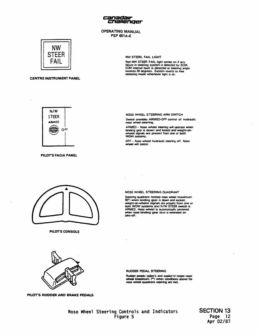
NW STEER FAIL
C E N T R E INSTRUMENT PANEL
NW STEERL FAIL LIGHT
Red NW STEER FAIL light comes on if any failure in steering system is detected by ECM. ECM internal fault is detected or steering angle exceeds 55 degrees. System reverts to free castormg mode whenever light is on.
NOSE WHEEL STEERING ARM SWITCH
Switch provides ARMED-OFF control of hydraulic nose wheel steering.
ARMED - Nose wheel steering will operate when landing gear is down and locked and weight-on* wheels signals are present from one or both WOW systems.
OFF - Nose wheel hydraulic steering off. Nose wheel will castor.
P I L O T S FACIA PANEL
NOSE WHEEL STEERING QUADRANT
Steering quadrant rotates nose wheel (maximum 55°) when landing gear is down and locked. wetght-on-wheeis signals are present from one or both WOW systems and N/W STEER switch is ARMED. Hose wheel is automatically centered when nose landing gear strut is extended on take-off.
PILOTS CONSOLE
RUDDER PEDAL STEERING
Rudder pedals (pact's and copilot's) rotate nose wheel (maximum 7°) when conditions above for nose wheel quadrant steering are met.
P I L O T S RUDDER A N D BRAKE PEDALS
Nose Wheel Steering Controls and Indicators SECTION 13 Figure 5 Page 12
Apr 02/87
canaaair cftauenper OPERATING MANUAL
PSP 601A-6
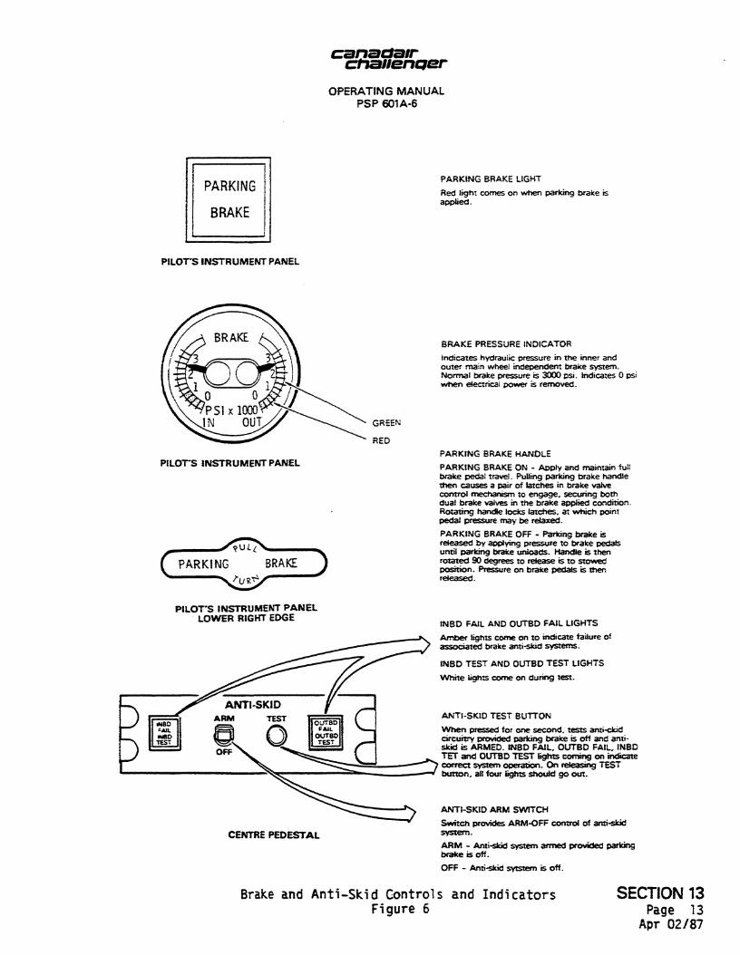
PARKING BRAKE LIGHT
Red light comes on when parking brake is applied.
PILOT'S INSTRUMENT PANEL
PILOT'S INSTRUMENT PANEL
C PARKING BRAKE J
BRAKE PRESSURE INDICATOR
Indicates hydraulic pressure in the inner and outer main wheel independent brake system. Normal brake pressure is 3000 psi. Indicates 0 psi when electrical power is removed.
PARKING BRAKE HANDLE
PARKING BRAKE ON - Apply and maintain full brake pedal travel. Pulling parking brake handle then causes a pair of latches in brake valve control mechanism to engage, securing both dual brake valves in the brake applied condition. Rotating handle locks latches, at which point pedal pressure may be relaxed.
PARKING BRAKE OFF - Parking brake is released by applying pressure to brake pedals until parking brake unloads. Handle is then rotated 90 degrees to release is to stowed position. Pressure on brake pedals is then released.
PILOT'S INSTRUMENT PANEL LOWER RIGHT EDGE
CENTRE PEDESTAL
INBD FAIL AND OUTBD FAIL LIGHTS
Amber lights come on to indicate failure of associated brake anti-skid systems.
INBD TEST AND OUTBD TEST LIGHTS
White lights come on during test.
ANTI-SKID TEST BUTTON
When pressed for one second, tests anti-ckid circuitry provided parking brake is off and antiskid is ARMED. INBD FAIL, OUTBD FAIL, INBD TET and OUTBD TEST lights coming on indicate correct system operation. On releasing TEST button, all four lights should go out.
ANTI-SKID ARM SWITCH
Switch provides ARM-OFF control of anti-skid system.
ARM - Anti-skid system armed provided parking brake is off.
OFF - Anti-skid sytstem is off.
Brake and Anti-Skid Controls and Indicators Figure 6
SECTION 13 Page 13
Apr 02/87