Embed Size (px)
Citation preview

OPERATING MANUALINV2500-HS SERIES
INVERTERS & SHELVES
www.unipowerco.com
Manual No. INV2500HS-6 © 2015 UNIPOWER LLCAll Rights Reservedinv2500-man-rev6-0115.indd
NORTH AMERICA • 3900 Coral Ridge Drive, Coral Springs, Florida 33065, USA • Tel: +1 954-346-2442 • Fax: +1 954-340-7901 • [email protected] • Parkland Business Centre, Chartwell Road, Lancing BN15 8UE, ENGLAND • Tel: +44(0)1903 768200 • Fax: +44(0)1903 764540 • [email protected]

Page 2
INV2500HS SERIESINSTALLATION & OPERATING MANUAL
Manual No. inv2500hs-6 inv2500-man-rev6-0115.indd
Contents
1.0 INTRODUCTION ...............................................................................................................42.0 STANDARD FEATURES ...................................................................................................53.0 SUMMARY OF PRODUCT LINE .....................................................................................54.0 SAFETY WARNINGS.........................................................................................................65.0 WARRANTY (summary) ....................................................................................................66.0 UNPACKING AND INSPECTION .....................................................................................67.0 DESCRIPTION OF OPERATION ......................................................................................78.0 FRONT AND BACK PANEL DESCRIPTIONS ................................................................79.0 SPECIFICATIONS ..............................................................................................................910.0 MECHANICAL DIMENSIONS OF SHELVES ...............................................................1011.0 SAFETY AND INDUSTRY STANDARDS ......................................................................1112.0 OPERATING INFORMATION .........................................................................................1113.0 PARALLEL OPERATION ................................................................................................1514.0 INSTALLATION AND TESTING ....................................................................................1615.0 INVERTER APPLICATION .............................................................................................1816.0 REPLACING AN INVERTER MODULE ........................................................................1917.0 MAINTENANCE ..............................................................................................................1918.0 TROUBLESHOOTING GUIDE .......................................................................................20

Page 3
INV2500HS SERIESINSTALLATION & OPERATING MANUAL
Manual No. inv2500hs-6 inv2500-man-rev6-0115.indd
FIGURES
Figure 1 - INV2500-HS Inverter Module and Shelf with 2 Modules Installed ...............................4Figure 2 - Front and Back of INV2500-HS Module ........................................................................7Figure 3 - Front and Back of INVR2U-HS Shelf ............................................................................8Figure 4 - Mechanical Dimensions of INVR2U-HS Shelf ............................................................10Figure 5a - Full Load Step. Vo (top) & lo (botA20A/cm) .............................................................11Figure 5b - Sudden Overload Applied. Vo (top) & lo (bot@50A/cm) ...........................................12Figure 5c - INV2500-HS Inverter Output Waveforms ..................................................................12Figure 6 - INV2500-HS Overload CharacteristicFigure ................................................................13Figure 7 - Connections for ORing Form C Relay Outputs ............................................................14Figure 8 - Two 115VAC Shelves in Parallel Using AC Distribution Panel ...................................16Figure 9 - Two 115VAC Shelves in Parallel Using AC Distribution Panel ...................................17Figure 10 - Operating Two Inverter Shelves in Parallel ................................................................18

Page 4
INV2500HS SERIESINSTALLATION & OPERATING MANUAL
Manual No. inv2500hs-6 inv2500-man-rev6-0115.indd
OPERATING MANUALINV2500-HS SERIES INVERTERS & SHELVES
1.0 INTRODUCTION
1.1 This Operating Manual should be read through carefully before installing and operating the INV2500-HS inverter modules and shelves. See Figure 1.
1.2 The INV2500-HS is a 2500 volt-ampere, hot-swap, DC to AC inverter module. It converts a nominal 48VDC input into a 115 or 230VAC output at 50 or 60Hz. These modules are designed to go into a 19-inch, hot-swap compatible shelf, INVR2U-HS, which holds one or two units. When two modules are used in this shelf they are automatically connected in parallel and synchronized to produce 5000 volt-amperes at 115VAC output (44 amperes) or 230VAC output (22 amperes). Or they can be operated in a 1+1 redundant mode at 2500 volt-amperes.
1.3 The48VDCnominalinputhasarangeof42to56VDC.Theinvertersachieve90%efficiencyand 7VA per cubic inch power density. Input and output are both circuit breaker protected. They have high surge capability for starting loads such a motors, but the output breaker quicklytripsifpowerattemptstoflowbackintoafaultedinverter.
1.4 These inverters can be paralleled for higher output power or for N+1 redundant applications. They are fully isolated from the battery. Front panel LEDs indicate inverter status, and Form C relay alarm contacts are available on the back. The units are self-cooled by internal fans.
1.5 In this manual, unless otherwise stated, INV2500-HS shall generally refer to both INV2500-HS and INV2500H-HS (115 and 230VAC) inverter models. Likewise INVR2U-HS shall generally refer to both INVR2U-HS and INVR2U-HS-H shelf models.
Figure 1 - INV2500-HS Inverter Module and Shelf with 2 Modules Installed

Page 5
INV2500HS SERIESINSTALLATION & OPERATING MANUAL
Manual No. inv2500hs-6 inv2500-man-rev6-0115.indd
2.0 STANDARD FEATURES
The following is a summary of the important features of the INV2500-HS module and INVR2U-HS shelf:
Two Mounting Positions High: 3.5 Inches 90%TypicalEfficiency 2500VA Output for INV2500-HS Up to 300% Surge Capability 5000VA Output for Two Units in Shelf Powers Reactive Loads 7VA per Cubic Inch Power Density Circuit Breaker Input & Output Protection 115VAC Output at 22 or 44 Amperes N+1 Redundant Operation 230VAC Output at 11 or 22 Amperes 19- or 23-Inch Rack Mounting Low Distortion 50 or 60Hz Sine Wave Overtemperature Protection 42 to 56VDC Input Form C Relay Alarm Contacts Fully Isolated from Battery Input LED Status Indicators Rear Safety Cover on Shelves
3.0 SUMMARY OF PRODUCT LINE
3.1 MODULES
MODEL INPUT OUTPUT FREQUENCY
INV2500-HS-60-E
42-56VDC
115VAC @ 22A60Hz
INV2500-HS-50-E 50Hz
INV2500H-HS-60-E230VAC @ 11A
60Hz
INV2500H-HS-50-E 50Hz
INV2500-HS-60*115VAC @ 22A
60Hz
INV2500-HS-50* 50HzNOTE: *These two models have the AC neutral output grounded to chassis. The other four models (-E) have floating AC neutral outputs.
3.2 SHELVES
MODEL OUTPUTVOLTAGE SIZE HEIGHT MODULE
CAPACITYMAXIMUMOUTPUT
INVR2U-HS 115VAC19-Inch 2RU 2 5kVA
INVR2U-HS-H 230VAC

Page 6
INV2500HS SERIESINSTALLATION & OPERATING MANUAL
Manual No. inv2500hs-6 inv2500-man-rev6-0115.indd
4.0 SAFETY WARNINGS
4.1 These inverters have hazardous external and internal voltages. They should be handled, testedandinstalledonlybyqualifiedtechnicalpersonswhoaretrainedintheuseofpowersystems and are well aware of the hazards involved.
4.2 The input and output terminals are at hazardous voltage potentials. Do not touch these areas when power is applied.
4.3 When operating these inverters, the chassis ground terminal must be connected to safety ground to minimize electrical shock hazard and to ensure low EMI (electromagnetic interference).
4.4 The internal voltages are at hazardous potentials. The inverter covers should not be removed. There are no user-serviceable components in these units. Removing the covers of the inverters will void the warranty.
4.5 WARNING:Whenusing“floatingneutral”,OptionEontheINV2500-HSmoduleorstandardontheINV2500H-HSmodule,theACneutraloutputterminal“N”isfloatingwithrespecttoACandchassisground.Aneutral-to-groundconnectionmustbere-establishedexternaltotheinverterandbeincompliancewiththerequirementsoftheend-useapplication.
5.0 WARRANTY (summary)
INV2500HS Series Inverters and Shelves are warranted for two (2) years from date of shipment against defects in material and workmanship. This warranty does not extend to products which have been opened, altered or repaired by persons other than persons authorized by the manufacturer or to products which become defective due to acts of God, negligence or the failure of customer to fully follow instructions with respect to installation, application or maintenance.
For a complete text of UNIPOWER’s warranty conditions please request a copy from your local SalesOffice.
6.0 UNPACKING AND INSPECTION
6.1 This INV2500-HS or INVR2U-HS was carefully tested, inspected and packaged for shipment from our factory. Upon receipt of the unit, it should be carefully unpacked and inspected for any damage in shipment.
6.2 If there is evidence of damage, do not attempt to test the unit. The freight carrier should be notifiedimmediatelyandaclaimforthecostoftheinvertershouldbefiledwiththecarrierfor direct reimbursement. Be sure to include the model and serial number of the damaged unit in all correspondence with the freight carrier. Also save the shipping carton and packing material as evidence of damage for the freight carrieir’s inspections.

Page 7
INV2500HS SERIESINSTALLATION & OPERATING MANUAL
Manual No. inv2500hs-6 inv2500-man-rev6-0115.indd
6.3 UNIPOWER will cooperate fully in case of any shipping damage investigation.
6.4 Always save the packing materials for later use in shipping the unit. Never ship the inverter without proper packing.
7.0 DESCRIPTION OF OPERATION
7.1 The INV2500-HS modules employ MOSFET and IGBT power semiconductor switches with advanced, microprocessor controlled, high-frequency, pulse modulation techniques toproducealow-distortion,50or60Hzsinewaveoutputwith90%efficiencyand7VAper cubic inch power density. A synchronization circuit lets two or more inverter modules operate in parallel with their outputs in phase-synchronization and current shared.
7.2 Two INV2500-HS inverter modules in an INVR2U-HS shelf are automatically connected in parallel in the shelf and become an inverter system with a 115VAC or 230VAC output at 5,000 volt-amperes.
8.0 FRONT AND BACK PANEL DESCRIPTIONS
8.1 Figure 2 shows the front and back of an INV2500-HS inverter module. On the left side of the front panel of the INV2500-HS is the input circuit breaker. To the right are the two cooling fans and the output circuit breaker. Above the output breaker from the top are the green LED indicators for Input OK, Sync OK and Output OK.
FRONT VIEW
BACK VIEW
Figure2-FrontandBackofINV2500-HSModule
HOT-SWAPCONNECTOR

Page 8
INV2500HS SERIESINSTALLATION & OPERATING MANUAL
Manual No. inv2500hs-6 inv2500-man-rev6-0115.indd
8.2 On the INV2500-HS back panel on the right side is the hot-swap connector which contains all power and signal connections.
8.3 Figure 3 shows the front and back of an INVR2U-HS or INVR2U-HS-H shelf. Each half of this shelf (side A or B) has an INV2500-HS. The back panel INV2500-HS has a transparent plastic safety cover. The INVR2U-HS shelf with two INV2500-HS inverters in it has a front retention panel over the inverter modules.
FRONT VIEW
BACK VIEW
Figure3-FrontandBackofINVR2U-HSShelf
8.4 On the back panel to the left are the AC output screw terminals. At the center is a terminal strip with the Form C relay contacts N.O., C and N.C. for each side (A and B) of the inverter system. To the right are the input bus bars with no. 1/4-20 studs. At the lower far right is the no. 10-32 stud chassis ground connection.

Page 9
INV2500HS SERIESINSTALLATION & OPERATING MANUAL
Manual No. inv2500hs-6 inv2500-man-rev6-0115.indd
9.0 SPECIFICATIONS
Specificationstypicalat48Vinput,fullloadand25°Cunlessotherwisenoted.
INPUTVoltage Range ..................................................................................................................................42-56 VDCInput Current, Full Load, 48VDC ......................................................................................................<60A DCInput Current, No Load, 48VDC ..........................................................................................................<1A DCInput Protection ...............................................................................................................100A Circuit BreakerEMI Filter, Conducted ............................................................... FCC2078 pt.15J Curve A, EN55022 Curve AVoice Band Noise, 240 A-H Battery ................................................................................................. <32dBrnC
OUTPUTVoltage, Full Load ................................................................................................................... 115 or 230 VACVoltage, No Load ..................................................................................................................... 120 or 240 VACCurrent, Max. 115VAC ........................................................................................................................................ 22A RMS 230VAC ........................................................................................................................................ 11A RMSFrequency ............................................................................................................................50 or 60Hz, ±0.1%Total Harmonic Distortion ..........................................................................................................................<2%Load Crest Factor .................................................................................................................................. 2.8 to 1Output Protection ...............................................................................................................25A Circuit BreakerSurge Capability .............................................................................................................................Up to 300%Reactive Loads ...................................................................................................................+90°to-90°PhaseEfficiency .................................................................................................................................................... 90%
SAFETY STANDARDS ......................................................UL60950-1, CSA22.2 No.60950-1, EN60950-1
STATUSINDICATORSInput OK ..........................................................................................................................................Green LEDSync OK ..........................................................................................................................................Green LEDOutput OK .......................................................................................................................................Green LEDForm C Relay Alarm Contacts ........................................................................................... Inverter Fail Alarm
ENVIRONMENTALOperating Temp. Range ..................................................................................................................0°Cto70°COutput Current Derating ...............................................................................................2.5%/°C,50°Cto70°CStorage Temp. Range ................................................................................................................ -40°Cto+85°CHumidity ............................................................................................................. 0% to 95%, Non-CondensingCooling ......................................................................................................................................... Internal Fans
PHYSICALSPECIFICATIONSCase Material, Module .....................................................................................................................AluminumShelf ........................................................................................................................................................... SteelDimensions, Inches (mm) Inverter Module .................................................................. 3.32 H x 8.50 W x 12.25 D (84.3 x 216 x 311) Shelf .................................................................................. 3.46 H x 18.32 W x 16.38 D (87.9 x 465 x 416)Rack Mounting Width ...............................................................................................................19 or 23 InchesWeight, Module ................................................................................................................... 11.50 lbs. (5.22kg)

Page 10
INV2500HS SERIESINSTALLATION & OPERATING MANUAL
Manual No. inv2500hs-6 inv2500-man-rev6-0115.indd
10.0 MECHANICAL DIMENSIONS OF SHELVES
Figure 4 shows the complete mechanical dimensions for the INVR2U-HS and INVR2U-HS-H shelves. The shelves are identical at 16.38 inches (416mm) deep; with the rear plastic cover they are 18.00 inches (457mm) deep.
3.46(87.9)
17.38(441)
Figure4-MechanicalDimensionsofINVR2U-HSShelf

Page 11
INV2500HS SERIESINSTALLATION & OPERATING MANUAL
Manual No. inv2500hs-6 inv2500-man-rev6-0115.indd
11.0 SAFETY AND INDUSTRY STANDARDS
11.1 TheINV2500-HSinvertermodulesmeetthefollowingsafetycertifications:
UL60950-1 CSA22.2 No. 60950-1 EN60950-1
11.2 The INV2500-HS inverter modules are CE marked to indicate conformance to the European Union’s Low Voltage Directive.
11.3 Input conducted EMI meets FCC20780 part 15J Curve A and EN55022 Curve A.
11.4 Input voice band noise is less than 32dBrnC for a single INV2500-HS with a 240 ampere-hour battery or two INV2500-HSs with a 480 ampere-hour battery.
12.0 OPERATING INFORMATION
12.1 InputVoltage. These telecom inverters operate off a nominal 48VDC input source which may be a battery or other DC source. The input voltage range is 42 to 56VDC. Input connections on the back of the INVR2U-HS shelf are to bus bars with no. 1/4-20 studs.
12.2 OutputVoltage. The output voltage for an INV2500-HS is 115VAC at full load, 120VAC at no load; for an INV2500H-HS it is 230VAC at full load, 240VAC at no load. See Figure 5(a). Frequency is 50 or 60Hz, ±0.1%. The output voltage has total harmonic distortion of less than 2.0%. The load current crest factor is 2.8 to 1, and surge capability is up to 300%. The output will drive reactive loads with up to ±90o phase angle. The output connectors are screw terminals on the back of the INVR2U-HS shelf.
Figure5a-FullLoadStep.Vo(top)&lo(botA20A/cm)

Page 12
INV2500HS SERIESINSTALLATION & OPERATING MANUAL
Manual No. inv2500hs-6 inv2500-man-rev6-0115.indd
Figure5b-SuddenOverloadApplied.Vo(top)&lo(bot@50A/cm)
Figure5c-INV2500-HSInverterOutputWaveforms
12.3 OutputPower. Maximum output power for an INV2500-HS module is 115VAC at 22A RMS or 230VAC at 11A RMS, giving a maximum of 2530 volt-amperes. For two modules in a shelf it is 115VAC at 44A or 230VAC at 22A, giving a maximum of 5060 volt-amperes. Exceeding these values may cause electronic shutdown of the output. Full output power isproducedatupto50°Cambienttemperature.Abovethis,outputcurrentmustbederatedat2.5%/°C.Maximumoperatingtemperatureis70°C,atwhichtheoutputcurrentmustbederated by 50%.
12.4 OverloadCharacteristic. These inverters incorporate electronic shutdown circuitry; shutdown takes place during an overload, before the output circuit breaker trips. Figure 5 shows INV2500-HS output voltage and current waveforms for a full load step, sudden overload, and short circuit. Figure 6 shows shutdown time versus output current for both the INV2500-HS and INV2500H-HS.

Page 13
INV2500HS SERIESINSTALLATION & OPERATING MANUAL
Manual No. inv2500hs-6 inv2500-man-rev6-0115.indd
Figure6-INV2500-HSOverloadCharacteristicFigure
Below is a table that shows the same information in a different format:
Typical Load Current vs. Shutdown TimePERCENT OF RATED LOAD
SHUTDOWNTIME
114-173% 10 sec.172-223% 1 sec.223 - 318% 0.25 sec.
As the table shows, the INV2500-HS is capable of handling large output surge currents, specificallymorethanthreetimesratedoutputcurrentfor1/4second,morethantwiceratedoutput current for 1 second and more than 1.5 times rated output current for 10 seconds. If the surge exceeds approximately 318% of rated output current or exceeds the shutdown times shown in the table, the output will be shut down and must be reset by turning both input and output circuit breakers off. After this, the input breaker(s) should be turned back on (up position); after the Output OK LED(s) come on the output breaker(s) should be turned back on (up position).
12.5 Grounding. It should be noted that in the standard INV2500-HS models, both AC ground and AC neutral are connected to case ground. For INV2500-HS Option E versions and INV2500H-HSmodels,ACneutralisfloatingandmustbeexternallyconnectedtosystemground.InbothversionstheDCinputterminalsarebothfloating.
12.6 StatusIndicators. Three green LEDs indicate the operating status of each INV2500-HS inverter module. They are (from top to bottom): Input OK, Sync OK and Output OK.

Page 14
INV2500HS SERIESINSTALLATION & OPERATING MANUAL
Manual No. inv2500hs-6 inv2500-man-rev6-0115.indd
12.7 FormCRelayContacts. These contacts at the rear of the shelf have normally open (N.O.) and normally closed (N.C.) positions for normal operation of each inverter module, see Figure 3 for connections. Note that there is a separate set of contacts for each module (A and B sides) of the inverter system. If it is desired to monitor the inverter system as a whole, the two sets of contacts may be connected as shown in Figure 7 to give an OR function for either set of contacts.
(a) Normally Open (b) Normally Closed
Figure7-ConnectionsforORingFormCRelayOutputs
12.8 SyncConnections. There are +Sync and -Sync terminals on the terminal block. When two or more inverters are connected in parallel these Sync terminals must be connected together, observing the polarities.
12.9 InverterModuleConnections. If the INV2500-HS inverter module is operated or tested separately from the shelf, connections should be made to the J1 connector with a mating connector and the pin connections given below.
PIN FUNCTION PIN FUNCTION PIN FUNCTION1 AC Line 12 nc 23 nc
3 2 1
6 5 4
9 8 7
24 23 22
27 26 25
30 29 28
33 32 31
11 1013 12 15 1417 16 19 1821 20
2 nc 13 nc 24 nc3 AC Line 14 + Sync 25 + DC In4 nc 15 - Sync 26 - DC In
5 AC Neutral 16 Form C: NC 27 - DC In
6 nc 17 Form C: C 28 + DC In7 AC Ground 18 Form C: NO 29 nc8 AC Neutral 19 nc 30 - DC In9 nc 20 nc 31 + DC In
10 nc 21 nc 32 + DC In11 nc 22 nc 33 - DC In
nc = No Connection
NOTE: Standard INV2500-HS modules have AC Neutral internally connected to AC Ground and Case Ground. “-E” version modules have floating AC Neutral.
J1 Connector: Positronics GFSH01M182
Mating Connector: Positronics GFSH01F10Contacts No. FC112N2 for Pins 1, 3, 5, 7, 8, 25-28 and 30-33.Contacts No. FC720N2 for Pins 14-18.

Page 15
INV2500HS SERIESINSTALLATION & OPERATING MANUAL
Manual No. inv2500hs-6 inv2500-man-rev6-0115.indd
13.0 PARALLEL OPERATION
13.1 The INV2500-HS and INV2500H-HS Series inverter modules are designed to operate in parallel for higher output current. The modules are automatically connected in parallel in the shelf. Two or more inverter shelves may also be connected in parallel for additional output power or for N+1 redundant operation. This is done by connecting all inputs in parallel and all outputs in parallel (line, neutral, line), although the DC inputs could come from two separate sources. In addition, the sync terminals must be connected together, +Sync to + Sync and -Sync to -Sync. The Sync terminals are used only for parallel connection of two or more inverters. Current sharing between paralleled inverters is ±10%.
13.2 Alternatively, separate sources may be used for the inputs to these inverters while the outputs are connected in parallel. In either case, output loads should have individual distribution circuit breakers. The following table shows output current and total volt-amperes for inverter modules connected in parallel.
# INV2500-HSINVERTERS
KVARATING
115VACAMPS
230VACAMPS
1 2.5 22 112 5.0 44 223 7.5 66 334 10.0 88 44
13.3 Four INV2500-HS inverter modules in two INVR2U-HS shelves connected in parallel could be used to produce 10 kilovolt-amperes or could also be used as a 3+1 redundant inverter providing 7.5 kilovolt-amperes to a load.
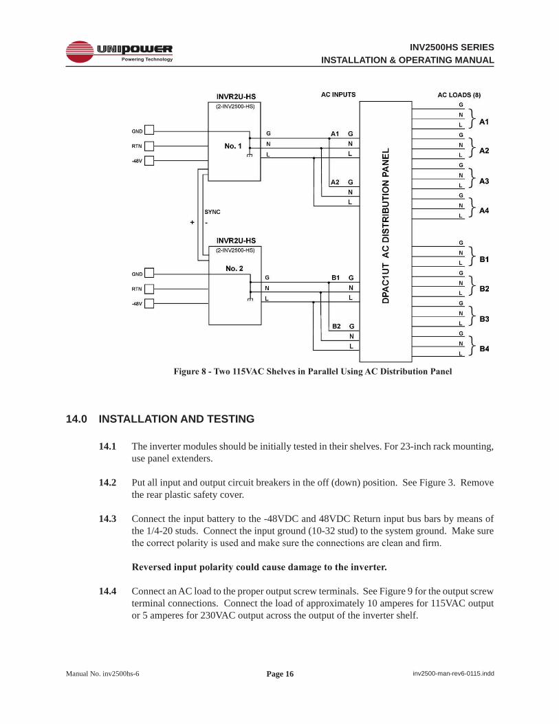
13.4 Figure 8 shows four INV2500-HS inverter modules in two INVR2U-HS shelves connected in parallel to give 10KVA of AC output at 115VAC. The AC output is distributed by a DPAC1UT AC Distribution Panel made by UNIPOWER. Note that only 115VAC inverter modules can be used with the DPAC1UT distribution panel, and not the 230VAC. Note also that only the “T” (Terminal Strip) Option of the DPAC1U can be used with these inverters and that, as shown in Figure 9, the A side AC input terminals must be strapped in parallel, i.e., A1G to A2G, A1N to A2N and A1L to A2L; in the same way, the B side AC input terminals must also be strapped in parallel.
Page 16
INV2500HS SERIESINSTALLATION & OPERATING MANUAL
Manual No. inv2500hs-6 inv2500-man-rev6-0115.indd
Figure8-Two115VACShelvesinParallelUsingACDistributionPanel
14.0 INSTALLATION AND TESTING
14.1 The inverter modules should be initially tested in their shelves. For 23-inch rack mounting, use panel extenders.
14.2 Put all input and output circuit breakers in the off (down) position. See Figure 3. Remove the rear plastic safety cover.
14.3 Connect the input battery to the -48VDC and 48VDC Return input bus bars by means of the 1/4-20 studs. Connect the input ground (10-32 stud) to the system ground. Make sure thecorrectpolarityisusedandmakesuretheconnectionsarecleanandfirm.
Reversedinputpolaritycouldcausedamagetotheinverter.
14.4 Connect an AC load to the proper output screw terminals. See Figure 9 for the output screw terminal connections. Connect the load of approximately 10 amperes for 115VAC output or 5 amperes for 230VAC output across the output of the inverter shelf.

Page 17
INV2500HS SERIESINSTALLATION & OPERATING MANUAL
Manual No. inv2500hs-6 inv2500-man-rev6-0115.indd
Figure9-Two115VACShelvesinParallelUsingACDistributionPanel
WARNING:Whenusing“floatingneutral”, versionEof the INV2500-HSmoduleandstandardwiththeINV2500H-HSmodule,theACneutraloutputterminal“N”isfloatingwithrespecttochassisground.Aneutral-to-groundconnectionmustbere-establishedexternaltotheinverterandbeincompliancewiththerequirementsoftheend-useapplication.
14.5 Insert an inverter module into the A side (left) of the shelf. To power up the inverter, turn the DC input circuit breaker on by moving the toggle to the up position. The fans and input OK and Sync OK LEDs should come on followed by the Output OK LED approximately four seconds later. After the Output OK LED is on, turn on AC output breaker by placing the toggle in the up position. Check the AC voltage across the load with a digital AC voltmeter. The voltage should be approximately 115VAC or 230VAC, depending on the model.
14.6 Check the Form C Relay contacts with an ohmmeter. See Figure 3. Measure the resistance between the N.O. contacts and C contacts. They should indicate an open. Measure the resistance between the N.C. contacts and the C contacts. They should indicate a short.
14.7 TurnofftheACoutputcircuitbreakersfirst,followedbytheDCinputbreakers,byplacingthe toggles in the down position. Remove the module from the shelf. Test each inverter in the manner described above.

Page 18
INV2500HS SERIESINSTALLATION & OPERATING MANUAL
Manual No. inv2500hs-6 inv2500-man-rev6-0115.indd
15.0 INVERTER APPLICATION
15.1 In the actual application of the inverter system, follow the procedure in sections 14.2 through 14.6, except the system should be connected to its actual load. The loads connected to the output of the inverter should always have their own individual circuit breakers. Make connections to the Form C relay contacts as required. Then re-install the rear plastic safety cover. Also install the front retention panel when all inverters are in the shelf.
15.2 For two or more inverter shelves in parallel, make the input and output connections to the inverters as described in Section 13.0. See Figure 10. Put all external distribution circuit breakers in the off position. Connect the sync terminals together observing proper polarity.
Figure10-OperatingTwoInverterShelvesinParallel
15.3 Take one of the inverter modules and turn the DC input circuit breaker on; then after the Output OK LED has come on, turn the AC output circuit breaker on. Repeat this for each paralleled inverter in turn until all inverters are on. Make sure that the three green LEDs are on for each inverter.
15.4 With all inverters on, turn on each external AC distribution circuit breaker. The inverters will automatically share output currents to an accuracy of ± 10%.

Page 19
INV2500HS SERIESINSTALLATION & OPERATING MANUAL
Manual No. inv2500hs-6 inv2500-man-rev6-0115.indd
16.0 REPLACING AN INVERTER MODULE
16.1 The following instructions are for replacing an INV2500-HS inverter module in an INVR2U-HS shelf.
16.2 When the INV2500-HS inverters are operated in N+1 redundant mode, only the inverter module being replaced needs to be turned off as described in the following paragraphs. In this case it is true hot-swap replacement. If the shelf is operated with two modules at its full 5,000 volt-ampere load, then both modules should be shut down in the manner described in paragraph 16.4. When starting up after replacement, both inverter modules must be turned on as described in paragraph 16.5.
16.3 Perform the following steps on the inverter module to be removed:
16.3.1 Turn off the AC output breaker (down position).
16.3.2 Turn off the DC input breaker (down position).
16.3.3 Remove the front retention panel by removing the four Phillips screws.
16.3.4 Remove the inverter module from its shelf.
16.4 To put a new inverter module in place, perform the following steps:
16.4.1 Make sure the input and output breakers of the new inverter module are in the off (down) position.
16.4.2 Install the replacement inverter module in the shelf.
16.4.3 Replace the front retention panel by replacing the four Phillips screws.
16.4.4 Turn on the DC input breaker (up position).
16.4.5 After the Output OK LED comes on, turn on the AC output breaker (up position).
16.4.6 All green LEDs on the inverter modules should now be on, indicating normal operation.
17.0 MAINTENANCE
No routine maintenance is required on the INV2500-HS Series except for periodic cleaning of dust and dirt around the front ventilation grill. A small vacuum nozzle should be used for this purpose.

Page 20
INV2500HS SERIESINSTALLATION & OPERATING MANUAL
Manual No. inv2500hs-6 inv2500-man-rev6-0115.indd
This document is believed to be correct at time of publication and UNIPOWER LLC accepts no responsibility for consequences from printing errors or inaccuracies. Specifications are subject to change without notice.
18.0 TROUBLESHOOTING GUIDE
If you encounter difficulty in getting the inverter(s) to operate, go through the following troubleshooting guide.
SYMPTOM POSSIBLE CAUSE ACTION TO TAKEInput OK LED does not come on.
Bad connection to input battery; input breaker not on.
Check the connection to battery; check battery voltage; check that input breaker is on.
Sync OK LED does not come on.
Bad connection to sync terminals.
Check that sync connection has been made to all paralleled inverters with proper polarity.
No AC output; Output OK LED does not come on.
Bad output connection; output breaker not on.
Check output connection to load; check that output breaker is on; check that AC distribution breakers are on.
No AC output; Output OK LED is off.
Short circuit or overload on output.
Remove short circuit or overload. Turn off input and output circuit breakers. Turn input circuit breaker back on, wait for the Output OK LED to come on, then turn the output circuit breaker on.
No output. Both circuit breakers on. Input and Output OK LEDs off.
Input battery voltage is below range.
Check battery voltage. Recharge battery or install new battery. Turn inverter back on.
Please note that there are no user serviceable parts inside either the modules or the shelves and that opening either will void the warranty.
IfyouarestillunabletoresolveanyproblemcallyournearestUNIPOWERsalesofficeforsupport: US +1 954 346 2442 UK +44 (0)1903 768200

INV2500-HS SERIESHOT-SWAP TELECOM INVERTERS
DESCRIPTION
Hot-Swap Replacement in Shelf Two Rack Spaces High: 3.5”
19- or 23-Inch Rack Mounting2500 VA Module Output5000 VA for Two Units in 19” Shelf7.2 VA per Cubic Inch Density115 VAC at 22 A or 230VAC at 11ALow Distortion 50 or 60Hz Sine Wave42 to 56 VDC InputFully Isolated from Battery Input90% Typical Effi ciencyUp to 300% Surge CapabilityCircuit Breaker Input & Output ProtectionPowers Reactive LoadsForm C Relay Alarm Contacts
UNIPOWER LLC’s INV2500-HS Series are 2500 volt-ampere, sine wave, hot-swap inverter modules which are available with a compatible, two-unit 19-inch shelf. The shelf is 2RU high (3.5 inches). The units operate off a 48VDC (42-56V range) input and produce either 115VAC output at 22A RMS or 230VAC at 11A RMS. Two units in the shelf produce 115VAC at 44A or 230VAC at 22A. The low distortion 50 or 60Hz sine wave is produced using MOSFET and IGBT power semiconductors with advanced, high-frequency, pulse-width modulation techniques which achieve 90% effi ciency and 7.2VA per cubic inch power density.
FEATURES
www.unipowerco.com
SAFETY STANDARDS
UL60950-1CSA22.2, No. 60950-1
EN60950-1
TWO-YEAR WARRANTY
NORTH AMERICA CALL: 954-346-2442 • EUROPE CALL: +44 (0)1903 768200
TELECOM INVERTER MODULES MODEL INPUT OUTPUT FREQUENCYINV2500-HS-60-E 42-56VDC 115VAC @ 22A 60Hz
INV2500-HS-50-E 42-56VDC 115VAC @ 22A 50Hz
INV2500H-HS-60-E 42-56VDC 230VAC @ 11A 60Hz
INV2500H-HS-50-E 42-56VDC 230VAC @ 11A 50Hz
INV2500-HS-60* 42-56VDC 115VAC @ 22A 60Hz
INV2500-HS-50* 42-56VDC 115VAC @ 22A 50Hz
INVERTER SHELVES MODEL OUTPUT
VOLTAGE SIZE HEIGHT MODULECAPACITY
MAXIMUMOUTPUT
INVR2U-HS 115VAC 19-Inch 2RU 2 5kVA
INVR2U-HS-H 230VAC 19-Inch 2RU 2 5kVA
NOTE: *These two models have the AC neutral output grounded to chassis. The other four models (-E) have fl oating AC neutral outputs.
The units can be paralleled for higher output power or for N+1 redundant applications. When operated in the shelf they are automatically paralleled. They are fully isolated from the telecom battery.
An input circuit breaker turns the inverter on and protects the battery from input faults. An output breaker connects the inverter to the load bus (after synchronization if the bus is live) and quickly disconnects the inverter in the event of an internal fault. The inverter has high surge capability (up to 300%) for starting loads such as motors, but the output breaker quickly trips if power attempts to fl ow back into a faulted inverter.
Front panel LEDs indicate inverter status, and Form C relay alarm contacts are available on the back. The units are self-cooled by internal fans.
2006/95/ECROHS2011/65/EU

UNIPOWER NORTH AMERICA • 3900 Coral Ridge Drive, Coral Springs, Florida 33065, USA • Tel: 954-346-2442 • Fax: 954-340-7901 • [email protected] UNIPOWER EUROPE • Parkland Business Centre, Chartwell Road, Lancing, BN15 8UE, ENGLAND • Tel: +44(0)1903 768200 • [email protected]
SPECIFICATIONS, INVERTER MODULESTypical at 48V Input, Full Load and 25°C Unless Otherwise Noted..
INPUTVoltage Range ................................................................................ 42-56 VDCInput Current, Full Load, 48VDC ........................................................<60A DCInput Current, No Load, 48VDC ...........................................................<1A DCInput Protection ............................................................... 100A Circuit BreakerEMI Filter, Conducted ............................................... FCC2078 pt.15J Curve A
A evruC 22055NEVoice Band Noise, 240 A-H Battery ..................................................<32dBrnC
OUTPUTVoltage, Full Load .................................................................... 115 or 230 VACVoltage, No Load ....................................................................120 or 240 VACCurrent, Max., 115VAC ......................................................................22A RMS
230VAC ..................................................................... 11A RMSFrequency .......................................................................... 50 or 60Hz, ±0.1%Total Harmonic Distortion ..........................................................................<2%Load Crest Factor ................................................................................. 2.8 to 1Output Protection ............................................................. 25A Circuit BreakerSurge Capability ............................................................................ Up to 300%Reactive Loads ..................................................................+90° to - 90° PhaseEffi ciency ...................................................................................................90%
SAFETY STANDARDS ......UL60950-1, CSA22.2 No.60950-1, EN60950-1
STATUS INDICATORSInput OK ......................................................................................... Green LEDSync OK ......................................................................................... Green LEDOutput OK ...................................................................................... Green LEDForm C Relay Alarm Contacts ............................................. Inverter Fail Alarm
ENVIRONMENTALOperating Temp. Range ................................................................ 0°C to 70°COutput Current Derating ...............................................2.5%/°C, 50°C to 70°CStorage Temp. Range ...............................................................-40°C to +85°CHumidity..............................................................0% to 95%, Non-CondensingCooling ........................................................................................ Internal Fans
PHYSICAL SPECIFICATIONSCase Material, Module ..................................................................... Aluminum
Shelf .................................................................................SteelDimensions, Inches (mm) Inverter Module .................................................3.32 H x 8.50 W x 12.25 D
)113 x 612 x 3.48( Shelf ................................................................3.46 H x 18.32 W x 16.38 D
)614 x 564 x 9.78(Rack Mounting Width ............................................................ 19 or 23 InchesWeight, Module ....................................................................11.50 lbs. (5.22kg)
ALL DIMENSIONS IN INCHES (mm).All specifi cations subject to change
without notice.
NOTES: 1. Standard 115VAC modules have neutral
connected to ground. “E” Option has a fl oatingneutral. Standard 230VAC modules have afl oating neutral (-E).
2. The hot-swap shelf comes with a rear, clearplastic safety cover which adds 1.62 inches toits depth.
3. 23-inch rack mounting requires panel extenders.
MODULE BACK VIEW
MODULE FRONT VIEW
8.50(216)
3.32(84.3)
HOT-SWAPCONNECTOR
18.32(465)
3.46(87.9)
SHELF FRONT VIEWEDIS BEDIS A
AC OUTPUTBREAKER
DC INPUTBREAKER
AC OUTPUTBREAKER
DC INPUTBREAKER
inv2
500-
HS
-ds-
revH
-071
5
OUTPUT FOR TWO INVERTERS IN A SHELF
OUTPUT VOLTS
OUTPUT kVA
OUTPUT AC AMPS
115VAC 5.0 44
230VAC 5.0 22
SHELF REAR VIEW
TUPNI CDTUPTUO CA ALARM & SYNC CONNECTIONS
PPAC SERIES PARALLELING PANELS
The outputs from multiple INVR2U inverter shelves can be easily paralleled together using the PPAC Series paralleling panels to provide a single bulk AC supply to the load. See separate datasheet.
© 2015UNIPOWER LLCThis document is believed to be correct at time of publication and Unipower LLC accepts no responsibility for consequences from printing errors or inaccuracies. All specifications subject to change without notice.