Embed Size (px)
Citation preview

Operating Manual
SMALL ENGINE CONTROL SYSTEM
Form GPN0100 with VSM+ OM 9-15

GPN0100 OM 7-15 GTI Operating Manual for Small Engines All rights reserved © ALTRONIC, LLC 2015 2
TABLE OF CONTENTS BY SECTION PAGE
1.0 OVERVIEW ..............................................................................................................3
2.0 GPN0100/GPN0100-12 PANEL ...............................................................................3
3.0 GCN0100 DISPLAY MODULE ...................................................................................4
4.0 MOUNTING ............................................................................................................4
5.0 WIRING ..................................................................................................................4
6.0 KEYPAD DESCRIPTION ...........................................................................................4
7.0 UNDERSTANDING THE HOME SCREENS .................................................................5
8.0 INITIAL CONFIGURATION ........................................................................................7
9.0 VSM+ GENERAL .....................................................................................................9
10.0 ADVANCED CONFIGURATION ................................................................................12
11.0 RS-485 COMMUNICATIONS ..................................................................................17
12.0 MODBUS REGISTER LIST ......................................................................................19
TABLE OF FIGURES
FIG. 1 MOUNTING DIMENSIONS ...................................................................................25
FIG. 2 WIRING DIAGRAM, CUSTOMER CONNECTIONS ....................................................26
FIG. 3 CUSTOMER WIRING, VSM+ .................................................................................26
FIG. 4 FLOW CHART .....................................................................................................27
FIG. 5 LADDER LOGIC ...................................................................................................28
FIG. 6 GPN0100 CHANNEL DESCRIPTION CHART ..........................................................28
FIG. 7 RS-485 COMMUNICATIONS: PC HOOK-UP ...........................................................29
FIG. 8 RS-485 COMMUNICATIONS: MULTIPLE SLAVE UNITS .........................................29

GPN0100 OM 7-15 GTI Operating Manual for Small Engines All rights reserved © ALTRONIC, LLC 2015 3
1.0 OVERVIEW 1.1 This manual applies to GPN0100, and GPN0100-12 panels used with Series 25
and 50 gas trains, S/N 1004 and up, kits for small, in-line engines.
1.2 The GPN0100 and GPN0100-12 control panels consist of the GCN0100 instrument, VSM+, wiring terminals, relay and fuse installed in an industrial polyester enclosure.
1.3 The GPN0100 and GPN0100-12 controllers are dedicated electronic microprocessor-based systems designed to sense manifold air pressure (MAP), exhaust gas temperature (EGT), and engine vibration (VIB) or a digital input point to control and monitor the GTI Bi-Fuel® natural gas fumigation system for diesel engines. A front mounted keypad serves as the user interface for all required system configuration. A backlit 128 x 64 character graphic display shows system status, programmed controller parameters and channel labels. The controller provides ON/OFF control function for the gas supply to the engine and provide complete supervisory and alarm annunciation capability in a low cost package dedicated to bi-fuel fumigation of diesel engines.
2.0 GPN0100/GPN0100-12 PANEL 2.1 The panel contains all the necessary hardware and provides the wiring interface
to external sensors. Conduit openings at the bottom of the enclosure provide access for supply power, sensor and other necessary wiring.
2.2 The GPN0100 must be powered by 24 vdc, and the GPN0100-12 must be powered by 12 vdc.
3.0 GCN0100 DISPLAY MODULE
3.1 The GCN0100 display module provides for monitoring the manifold air pressure (MAP), exhaust temperature (EGT), and engine vibration (VIB) or a normally closed digital input permissive. The output of the GCN0100 instrument pilots a control relay to open and close the gas supply solenoid valve.
3.2 The keypad is a sealed membrane unit containing MENU/ESC, UP, DOWN and ENTER keys, used to navigate through channel status and description and to edit the setpoints.
3.3 The LCD has a Home Screen that displays a Status Line, BI-FUEL OFF, BI-FUEL FAULT, TIMERS ACTIVE, BI-FUEL INHIBIT, or BI-FUEL ON, along with Manifold Air Pressure and Exhaust Temperature.
3.4 The keypad and display are used to navigate through channel status and descriptions, view screens, and to view or edit the system’s configuration. Pressing the MENU/ESC key advances the display to the menus. All menu adjustments are saved in non-volatile EEPROM memory by pressing the ENTER key. The EEPROM memory retains the current configuration during normal operation, after engine shutdown and a system power-down.
3.5 The GCN0100 has serial communications compliant to Modbus RTU standard
and uses RS-485 for its hardware communication format.
WARNING: Deviation from these instructions may lead to improper engine operation which could cause personal injury to operators or other nearby personnel.
NOTE: Engine must be equipped with an full authority governor to operate properly with the GTI Bi-Fuel system.
WARNING: The controller system must be configured prior to use. Reference section 8.0, INITIAL CONFIGURATION, for instructions describing how to configure the controller for the specific application. Verify the program in nonvolatile memory (the eeprom) prior to starting the system.

GPN0100 OM 7-15 GTI Operating Manual for Small Engines All rights reserved © ALTRONIC, LLC 2015 4
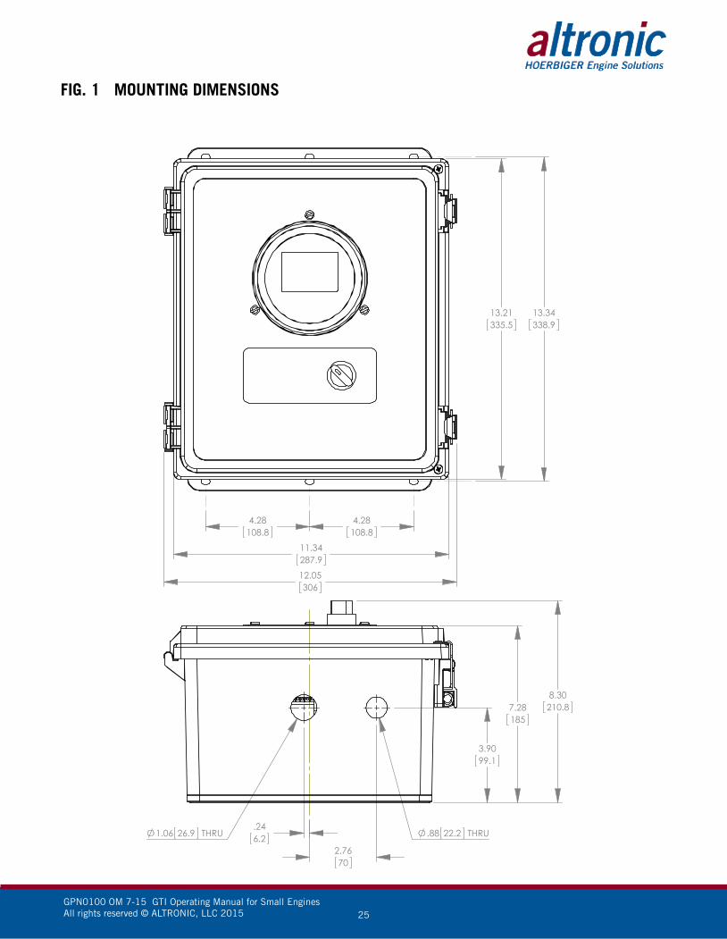
4.0 MOUNTING THE PANEL (FIG. 1)
4.1 Mount the control panel(s) to a post or to a suitable flat surface so that the display is at a convenient viewing height.
5.0 WIRING (SEE WIRING DIAGRAMS, FIG. 2)
5.1 Wire Cable Assembly 693136-x, where x may be either 1 (for 10-foot) or 2 (for 20-foot) cabling, into the panel. This assembly contains the wiring for the MAP, Exhaust Temperature, NC Digital Input, Power and Gas Solenoid Valve.
Feed the cable through the bottom of the panel and connect each wire to its appropriate position on the terminal strips.
5.2 VSM+ Sensor Harness consists of three main components, (662031 Conduit, 615107 VIB Sensor, and 693134-XX VIB Sensor Harness). These three components are assembled by the installer to create the VIB harness. Up to 8 sensors can be utilized at a length of up to 100 feet.
6.0 KEYPAD DESCRIPTION
6.1 The GCN0100 gauge features a four-key front keypad which is used to view or change the setpoint values, configure and calibrate the gauge. The front panel keys are MENU/ESC, ENTER, and , (up and down arrow keys).
6.2 MENU/ESC The MENU/ESC key is used to enter the main menu and to return to the home
screen at any time. If the MENU/ESC key is used to return to the home screen prior to pressing the ENTER key, changes are not stored in the memory and do not take effect.
6.3 ENTER The ENTER key is used throughout the menu to proceed through the
configuration and to accept the data to be saved. Throughout configuration when a change has been made and is to be saved to memory, press ENTER and the display will read SAVED, and the new data or configuration will be stored in the nonvolatile memory.
6.4 AND The up and down arrow keys are used to scroll through the selections in the
menu and to increase or decrease values during configuration and calibrations. Values can be changed incrementally using individual key presses or more rapidly by holding the key down.
NOTE: Avoid mounting the panel with the LCD display facing direct sunlight. The display operating temperature range is -31°F to +176°F (-35°C to +80°C). The panel(s) should be mounted within 10–20 feet of the engine, the fuel solenoid valve and sensors.
NOTE: All furnished drawings and instructions assume (–) ground DC system. In the case of a floating ground, or (+) ground DC system, please contact Altronic Factory for support.

GPN0100 OM 7-15 GTI Operating Manual for Small Engines All rights reserved © ALTRONIC, LLC 2015 5
7.0 UNDERSTANDING THE HOME SCREEN
7.1 The Home Screens shows the operating parameters on one screen.
The status line will read one of the following: BI-FUEL ON, BI-FUEL OFF, BI-FUEL FAULT, BI-FUEL INHIBIT, or TIMERS ACTIVE.
BI-FUEL ON
MANIFLD AIR PRES
CH1 psig0% 100%CH2 850 °F
25.7CHANNEL LABEL
5-DIGIT NUMERICAL VALUE
CHANNEL NUMBER & UNITSBARGRAPH (IF USED)
CHANNEL 2 VALUE & UNITS
STATUS OF FUEL VALVE
7.2 To activate the Bi-Fuel® system, turn on the power; the unit automatically resets.
TIMERS ACTIVE 23s
MANIFLD AIR PRES
18.4CH1 psig
CH2 62 °F
Upon a power-up, or exiting a setpoint violation, the GCN0100 counts down until the time expires.
BI-FUEL ON
MANIFLD AIR PRES
23.9CH1 psig
CH2 752 °F
Once the fuel delay timer ex-pires, and there are no setpoint violations on either channel and the digital input is closed, the GCN0100 turns on the relay, providing power to the solenoid valve.

GPN0100 OM 7-15 GTI Operating Manual for Small Engines All rights reserved © ALTRONIC, LLC 2015 6
BI-FUEL INHIBIT
MANIFLD AIR PRES
16.9CH1 psig
CH2 227 °F
If the normally-closed input is open, the GCN0100 displays BI-FUEL INHIBIT. The solenoid valve will not be powered with this message displayed.
BI-FUEL OFF
MANIFLD AIR PRES
28.6CH1 psig
CH2 662 °F
In this example, the Bi-Fuel® system is off because the mani-fold pressure has violated the high setpoint.
BI-FUEL FAULT
ENGINE EXHAUST
812CH2 °F
CH2 HI
If the engine exhaust tempera-ture exceeds the high setpoint, BI-FUEL FAULT will be displayed and the gas supply will be closed. To clear this fault, power must be cycled via the on/off switch on the front panel.

GPN0100 OM 7-15 GTI Operating Manual for Small Engines All rights reserved © ALTRONIC, LLC 2015 7
8.0 INITIAL CONFIGURATION8.1 This section will guide the user through the minimum screens required to set-up
the controller. A more detailed description of all user parameters is provided in section 10.
This system is shipped with factory default settings. SEE FIGURE 5. Upon power-up a splash screen displays: GTI logo, GCN0100, the firmware Rev. Level and date.
Press the following keys to enter the QUICK START MENU:
AUTOSCAN OFF~QUICK START-UP CHANNEL 1 CHANNEL 2 COMMUNICATIONS SECURITY
MENUESC
ENTER
ENTER QUICK START MENU~ UNITS ENGLISH FUEL DELAY 120S
PREVIOUS MENU
Once the arrow cursor is adjacent to the line to be changed, pressing the ENTER key changes the icon to é. Now the up and down arrow keys can be used to change the selection. Once the desired change is made, pressing the ENTER key saves the change and returns the arrow cursor.
ENTER QUICK START MENUé UNITS ENGLISH FUEL DELAY 120S
PREVIOUS MENU
NOTE: The splash screen can be displayed at anytime from a home screen by pressing both the up and down arrow keys together.

GPN0100 OM 7-15 GTI Operating Manual for Small Engines All rights reserved © ALTRONIC, LLC 2015 8
The up and down arrow keys can be used to move the cursor down to the PREVIOUS MENU. Pressing ENTER then returns the display to the main menu. Move the cursor adjacent to CHANNEL 1 and press ENTER.
AUTOSCAN OFF QUICK START-UP~CHANNEL 1 CHANNEL 2 COMMUNICATIONS SECURITY
ENTER
Next, press the DOWN ARROW twice, to move the arrow cursor adjacent to SETPOINTS as shown, followed by ENTER.
CHANNEL 1 UNITS psi FILTER 230~SETPOINTS CONFIGURE CALIBRATE RESET PREVIOUS MENU
ENTER
CHANNEL 1
~ HI 26.7 psig LO 2.5 psig
HYST 3 SEC
PREVIOUS MENU
Press ENTER again to change the cursor to the é icon. Use the UP and DOWN arrow buttons to make the desired setpoint changes. The procedure is repeated to change the second setpoint value.
GPN0100 OM 7-15 GTI Operating Manual for Small Engines All rights reserved © ALTRONIC, LLC 2015 9
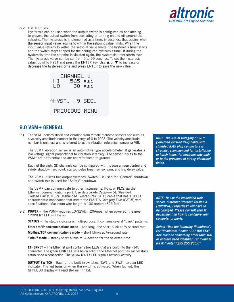
8.2 HYSTERESIS Hysteresis can be used when the output switch is configured as nonlatching
to prevent the output switch from oscillating or turning on and off around the setpoint. The hysteresis is implemented as a time, in seconds, that begins when the sensor input value returns to within the setpoint value limits. When the input value returns to within the setpoint value limits, the hysteresis timer starts and the switch stays tripped for the configured hysteresis time. If during the hysteresis time the setpoint is violated again, the hysteresis timer starts over. The hysteresis value can be set from 0 to 99 seconds. To set the hysteresis value, point to HYST and press the ENTER key. Use or to increase or decrease the hysteresis time and press ENTER to save the new value.
CHANNEL 1 HI 565 psi LO 30 psi
~HYST. 9 SEC. PREVIOUS MENU
9.0 VSM+ GENERAL9.1 The VSM+ senses shock and vibration from remote mounted sensors and outputs
a velocity amplitude number in the range of 0 to 1023. The velocity amplitude number is unit-less and is referred to as the vibration reference number or VIB.
The VSM+ vibration sensor is an automotive type accelerometer. It generates a low voltage signal proportional to vibration intensity. The sensor inputs to the VSM+ are differential and are not referenced to ground.
Each of the eight (8) channels can be configured with its own unique control and safety shutdown set point, startup delay timer, sensor gain, and trip delay value.
The VSM+ utilizes two output switches. Switch 1 is used for “Control” shutdown and switch two is used for “Safety” shutdown.
The VSM+ can communicate to other instruments, PC’s, or PLCs via the Ethernet communications port. Use data grade Category 5E Shielded Twisted Pair (STP) or Unshielded Twisted-Pair (UTP) cable that has a 100Ω characteristic impedance that meets the EIA/TIA Category Five (CAT-5) wire specifications. Maximum wire length is 100 meters (325 feet).
9.2 POWER – The VSM+ requires 10-32Vdc, .20Amps. When powered, the green “POWER” LED will be on.
STATUS – The status indicator is multi-purpose. It contains several “blink” patterns.
EtherNet/IP communications mode – one long, one short blink at ¼-second rate
Modbus/TCP communications mode – short blinks at ¼-second rate
“wink” mode – steady short blinks at 1/8-second for the selected time
ETHERNET – The Ethernet port contains two LEDs that are built into the RJ45 connector. The green LINK LED will be on solid if the Ethernet port has successfully established a connection. The yellow RX/TX LED signals network activity.
OUTPUT SWITCH – Each of the built-in switches (SW1 and SW2) have an LED indicator. The led turns on when the switch is activated. When faulted, the GPN0100 display will read Bi-Fuel Inhibit.
NOTE: The use of Category 5E STP (Shielded Twisted Pair) cable with shielded RJ45 plug connectors is strongly recommended for installation in harsh industrial environments and/or in the presence of strong electrical fields.
NOTE: To use the embedded web server, “Internet Protocol Version 4 (TCP/IPv4) Properties” will have to be changed. Please consult your IT department on how to configure your computer properly.
Select “Use the following IP address”.For “IP address:” enter “10.1.100.XXX” XXX must be something other than 100 or another used identifier. For “Subnet mask:” enter “255.255.255.0”

GPN0100 OM 7-15 GTI Operating Manual for Small Engines All rights reserved © ALTRONIC, LLC 2015 10
EDS File (Electronic Data Sheet) – The EDS file is used for Monitor configuration. This will be utilized if remote monitoring is required. Please reference VSM+ IOM for further detail.
Embedded Web Server – The VSM+ has a built in web server that must be used for VSM+ configuration. The embedded web server can also be used to view and set the network and protocol settings.
Once connected and powered, open your web browser and type the IP address assigned to the monitor. The default address is “http://10.1.100.100”
9.3 OUTPUT SWITCH 1 is designed to be used as CONTROL HIGH. The switch is activated when a control set point value is violated for any monitored sensor. Each sensor can be configured with a CONTROL HIGH set point.
Switch 1 can be configured as normally open (N/O) or normally closed (N/C).
Switch 1 should be configured N/O “FAILSAFE” to allow for normal bi-fuel operation.
OUTPUT SWITCH 2 is designed to be used as SAFETY HIGH. The switch is activated when a safety set point value is violated for any monitored sensor. Each sensor can be configured with a SAFETY HIGH set point.
Switch 2 can be configured as normally open (N/O) or normally closed (N/C).
Switch 2 should be configured N/O “SHELF” to allow for normal bi-fuel operation.
Switches 1 and 2 can be configured as Latching or Non-Latching. To configure channels to be use as a CONTROL HIGH set point, NON-LATCHING should be selected. To configure channels to be used as a SAFETY HIGH set point, LATCHING should be selected.
9.4 To configure the VSM+, connect to the embedded web server as describe in the note above. Select “General Setup” which is located in the menu bar on the left hand side of the screen. The General Setup screen will display on the computer. This screen is used to configure the VSM+ for the specific engine application.
Number of Channels (1-8) – allows the user to select between 1 and 8 vibration inputs.
Lag Filter Gain Value (1-255) – should not be changed (default value is 240)
Run Control – should be in the Run position. This tells the VSM+ to act or ignore exceeded set points.
Channel Name (0-12 chars) – allows the user to name each individual channel up to 12 characters
Gain – allows the user to bring the sensor value into a desired range. A starting value of .296 is recommended
Start Delay seconds (0-999) – allows the user to delay when the VSM+ starts looking for values above the programmed set point. A starting value of 0 is recommended.
Trip Delay seconds (0-15) – allows vibration values to exceed the programmed set point for a specified amount of time before an output switch is tripped. It is recommended that this value be 3 seconds or less.
Bad Sensor Setpoint (0-999) – is a value that is programmed to notify the user of a broken, bad, or disconnected sensor. A recommended starting value is 50.
Alarm Setpoint (0-999) – allows the user to set a Control Off set point
Shutdown Setpoint (0-999) – allows the user to set a Safety Shutdown setpoint
NOTE: Nomenclature translation on the embedded VSM+ configuration page.Alarm and Non-latch is ControlShutdown and Latch is SafetyCH1 Shelf is N/CCH1 Failsafe is N/OCH2 Shelf is N/OCH2 Failsafe is N/C

GPN0100 OM 7-15 GTI Operating Manual for Small Engines All rights reserved © ALTRONIC, LLC 2015 11
9.5 To view the VSM+ readings through computer select “Monitor” which is located in the menu bar on the left hand side of the screen. The Monitor screen will display on the computer. This screen is used to view the inputs to the VSM+.
For information on Network Settings and Protocol Settings, please consult the VSM+ IOM.

GPN0100 OM 7-15 GTI Operating Manual for Small Engines All rights reserved © ALTRONIC, LLC 2015 12
10.0 ADVANCED CONFIGURATIONTHE FOLLOWING REPRESENTS ADVANCED PROGRAMMING FEATURESWHICH SHOULD ONLY BE ATTEMPTED BY TRAINED PERSONNEL.
10.1 To change either selection, use the or arrow keys to select which parameter to change, and press ENTER. The changes to . Use the or arrow keys to change the selection and press ENTER. The value will be saved.
GENERAL INFORMATION WHEN NAVIGATING THE MENUS Press the MENU/ESC key to enter the main menu (shown below) from the
home screen. In the main menu are submenus for channel 1 and for channel 2. When navigating the gauge menus, use the or arrow keys to point to a menu selection and press ENTER, the ~ (arrow) will change to é. Use the or arrow keys to increase or decrease values or to scroll through the selections. After making a change, press the ENTER key to save the configuration to memory; the display will read SAVED. It is at this time the new data is saved. The MENU/ESC (escape) key can be used at any time to abort the menu and return to the home screen. During configuration, the gauge allows 15 seconds for first level and 2 minutes for other levels between keystrokes to change or save a new configuration. If the time lapses without a keystroke, the gauge will automatically return to the home screen without making any changes. The new information is saved only if the ENTER key is pressed and the gauge reads SAVED. A flowchart (fig. 4) is provided that shows step-by-step progression through the gauge configuration procedure.
10.2 AUTOSCAN — AUTOSCAN 1–30s /OFF Autoscan allows the user to scroll automatically between the two channels.
Autoscan can be set from 1 to 30 seconds or OFF. With AUTOSCAN turned on, when in the home screen, the gauge will display each channel for the selected time before automatically switching to the next channel. The arrow key can be used to quickly advance to the other channel. With AUTOSCAN turned OFF, the scanner continually displays one channel at a time. Press to display the next channel.
MENUESC AUTOSCAN OFF
QUICK START-UP~ CHANNEL 1 CHANNEL 2 COMMUNICATIONS SECURITY
REFER TO SECTION 8 FOR A DESCRIPTION OF THE QUICK START-UP MENUS.
WARNING: Section 10 presents advanced programming features which, if used improperly, can prevent the GPN0100 from operating correctly. This should only be attempted by trained personnel.

GPN0100 OM 7-15 GTI Operating Manual for Small Engines All rights reserved © ALTRONIC, LLC 2015 13
10.3 CHANNEL 1 (2)/CONFIGURATION MENUS Each of the following items: type of units, filter value, setpoint values,
calibration. To view or change the listed items for the respective channel, from the main menu, use the or arrow key to select channel 1 or 2 and press ENTER. Use or to point to the item to be viewed or changed and press ENTER. Following is a description of each item.
CHANNEL 1 MENU
ENTER CHANNEL 1~UNITS psi FILTER 230 SETPOINTS CONFIGURE CALIBRATE RESET PREVIOUS MENU
10.4 UNITS There are several units-of-measure available as standard selections in the
gauge. Only the units relevant to the selected input sensor type will be available. Following are the available units for each type of input sensor.
Pressure units: psi, psig, psia, KPa, bar, mbar, inH2O, inHg, mmH2O, mmHg, kg/cm², and torr
Temperature units: °F, °C, and °K
The unit indicators appear on the right side of the display. When changing to a new unit indicator, the displayed numeric value is automatically converted to the new unit value. To change the units, use the or key to point to UNITS and press the ENTER key; the previously programmed unit indicator will appear. Use the or key to select one of the available indicators, and press ENTER to accept and save the change. The display will read SAVED. To return to the home screen press MENU/ESC. The new unit indicator selected and the numeric value converted to the selected units will be displayed on the home screen.
10.5 FILTER The display filter can be used to stabilize the display reading of a changing
input. Filtering is done in both hardware and software. The software filter is adjustable; the rate of change is less for large values. The filter value is read-out in a number from 1 to 255, 1 being no filter value and 255 being maximum filter value. Below are some typical filter values and their effect on the display reading. Settling values are approximate times in seconds to reach 90% of new reading. To set the filter value, use the or key to point to FILTER and press ENTER. The display will read the previously set filter value. Use the or keys to increase or decrease the filter value and press ENTER to save the new filter value.
FILTER VALUE: 1 128 200 210 220 230 240 250 252 253 254 255
SETTLING, SEC. .20 .33 .60 1 1.5 2 3 9 14 19 28 55
10.6 SETPOINTS The SETPOINTS menu allows the user to set a setpoint value for Low and
High, and set the hysteresis value for each channel. REFER TO SECTION 8 FOR DETAILS ON SETPOINTS
10.7 CALIBRATE The gauge is calibrated at the factory and should not require additional
calibration. However, calibration can be performed in the field many times over the life of the gauge. Each channel is calibrated separately to the type of input transducer selected. The calibration mode is used to calibrate the zero
NOTE: During calibration, the unit allows 2 minutes between keystrokes to change or save a new calibration. If 2 minutes lapse without a keystroke, the device will automatically return to the home screen with the previous values. The new calibration information is saved only if the ENTER key is pressed and the display reads SAVED.

GPN0100 OM 7-15 GTI Operating Manual for Small Engines All rights reserved © ALTRONIC, LLC 2015 14
and span values. Calibration can be performed from the front keypad without disassembling the gauge. A calibrator or simulator capable of outputting the correct signal for the type of transducer selected for that channel is required to provide a calibration reference.
CHANNEL 1 CALIBRATE:~FULL CAL TWEAK LO ONLY TWEAK HI ONLY RECALL FACT CAL PREVIOUS MENU
10.7.1 CALIBRATION PROCEDURE Connect the appropriate calibrator or simulator (for thermocouples use the
proper type of thermocouple extension wire) to the gauge for channel 1 or 2, follow the hook-up drawing for that sensor type. Be sure that the sensor type and the engineering units of the calibrator match the type and engineering units of the instrument before performing a calibration.
To calibrate the gauge, select CALIBRATE from the channel 1 or 2 menu
and press the ENTER key. Select FULL CAL and press ENTER. The display will read SET LO POINT ON CALIBRATOR AND PRESS ENTER. Adjust the calibrator/simulator at or near zero or a very low reading and press ENTER; the display will show SAMPLING, then ADJUST LO POINT TO MATCH CALIBRATOR. Use the or arrow keys to increase or decrease the display reading to match the setting of the simulator and press ENTER. The display will show SET HI POINT ON CALIBRATOR AND PRESS ENTER. Adjust the simulator at or near the span value of the transducer or a very high reading and press ENTER; the display will show SAMPLING, then ADJUST HI POINT TO MATCH CALIBRATOR. Again use the or arrow keys to increase or decrease the display reading to match the simulator and press ENTER. The display will read CALIBRATION VALUES SAVED!. The gauge will return to the home screen with the new calibration values stored in memory.
10.7.2 The GCN0100 gauge has a feature that allows a slight adjustment of either the zero or span values individually. This type of calibration can be used to “tweak” the readout to match that of a known value without actually performing a formal calibration procedure. This adjustment is independent for each channel and must be performed on that individual channel. Please note that this type of adjustment will invalidate calibration settings from the FULL CAL procedures.
TWEAK LO ONLY To make a small adjustment on the zero calibration value of the gauge, enter
the calibration mode by selecting CALIBRATE and press ENTER; select TWEAK LO ONLY from the menu and press ENTER. The display will show SET LO POINT ON CALIBRATOR AND PRESS ENTER. Adjust the calibrator/simulator at or near zero or a very low reading and press ENTER; the display will show SAMPLING, then ADJUST LO POINT TO MATCH CALIBRATOR. Use the or arrow keys to increase or decrease the display reading to match the calibrator and press ENTER. The display will read CALIBRATION VALUES SAVED!. The gauge will return to the home screen with the new zero calibration value stored in memory.
TWEAK HI ONLY To make a small adjustment on the span calibration value of the gauge, enter
the calibration mode by selecting CALIBRATE and press ENTER; select TWEAK HI ONLY from the menu and press ENTER. The display will show SET HI POINT ON CALIBRATOR AND PRESS ENTER. Adjust the calibrator/simulator at or near the desired span value and press ENTER; the display

GPN0100 OM 7-15 GTI Operating Manual for Small Engines All rights reserved © ALTRONIC, LLC 2015 15
will show SAMPLING, then ADJUST HI POINT TO MATCH CALIBRATOR. Use the or arrow keys to increase or decrease the display reading to match the calibrator and press ENTER. The display will read CALIBRATION VALUES SAVED!. The gauge will return to the home screen with the new span calibration value stored in memory.
10.7.3 RECALL FACTORY CAL VALUES The user can at any time during the life of the gauge reinstate the factory
calibration values for channel 1 or 2 independently. Select CALIBRATE from the CHANNEL 1 or CHANNEL 2 menu and press ENTER; select RECALL FACTORY CAL and press ENTER. The next screen will display the type and range for which the selected channel’s input is currently configured. Select APPLY to confirm or CANCEL to decline and press ENTER. If APPLY is selected, the display will show CALIBRATION VALUES SAVED!. The gauge will return to the home screen with the factory default calibration values stored in memory. If CANCEL is selected, the gauge will retain the current calibration values. Press the ESC key to return to the home screen.
The calibration values only, will return to the factory default; all other settings will remain unchanged. If the transducer type or range is incorrect, press the MENU/ESC key to abort saving incorrect factory cal values. Configure the gauge for the desired input sensor type and range and then recall the factory cal values.
10.8 RESET The reset selection in the menu is used to reset the min/max reading for
channel 1 or 2 independently. To perform a reset, select either channel 1 or 2 from the menu, use or to scroll to RESET and press ENTER. The display will show RESET!. A reset can also be performed by sending a reset command via the RS-485 Modbus RTU communications register.
10.8.1 MIN/MAX READING Use the or arrow key to point to MIN/MAX READING and press ENTER;
The display will show RESET!. RESET resets both the min and max readings to the current reading.
CHANNEL 1 RESET:
~MIN/MAX READING
PREVIOUS MENU
10.9 COMMUNICATIONS
10.9.1 The GCN0100 gauge is part of a system that has been carefully designed to easily interface to popular computers, terminals, programmable controllers and Altronic instruments. Modbus RTU is the protocol used in the GCN0100. A Modbus register list with register numbers and descriptions of each register can be found in section 12.0. The serial communications are compliant to the Modicon Modbus RTU standard and uses RS-485 for its hardware communication format. To view or adjust the communication parameters, select COMMUNICATIONS from the main menu and press ENTER. Throughout the menu use the or arrow keys to make a selection and press ENTER to save the changes.
FOR DETAILED COMMUNICATIONS INFORMATION SEE SECTION 11.0.

GPN0100 OM 7-15 GTI Operating Manual for Small Engines All rights reserved © ALTRONIC, LLC 2015 16
COMMUNICATIONS ~NODE: 1 BAUD: 9600 PREVIOUS MENU
10.9.2 NODE The node number gives each gauge on the communications port an identity.
Any node number from 1 to 99 can be used. Use the up and down arrow keys to select a node number and press ENTER to save.
10.9.3 BAUD — Select the required baud rate and press ENTER to save.
SEE SECTION 11.3 FOR AVAILABLE BAUD RATES.
10.10 SECURITY
10.10.1 The security feature allows for a user to lock the gauge to secure chosen areas of the menu from being changed. There are several individual areas in the menu system that can be protected as well as two layers of protection. The menus that can be protected are the CONFIGURATION menu settings, the SETPOINT values, the ability to make changes via modbus COMMUNICATIONS, and CALIBRATION protection. When protection is ON, the user is able to view the menu values but not able to change them. If an attempt is made to change the values and the ENTER key is pressed when protection is on, the display will read PASSWORD PROTECTED! ENTER PASSWORD. This prompts the user to enter the password. If the correct password is entered, the requested configuration values can be changed.
To set or change a password, select SECURITY from the main menu and press ENTER. If the password is set to 000, the security menu will be available without entering the password. If the password is any number but 000, the proper password must be entered to enter the security menu. Each of the security selections can be turned ON or OFF individually. Use the or arrow key to point to the item to be protected and press ENTER, the é arrow will change to é. Use the or key to select either ON or OFF and press ENTER. The display will show SAVED and the change will be saved to memory. When a menu item is protected, the display will read ON, not protected will show as OFF. To enter a password, point to PASSWORD and press ENTER. Use the or arrow key to increase or decrease each of the 3-digit password numbers and press ENTER. The display will show SAVED and the change will be saved to memory. Any number from 000 to 999 can be used. Please note that Autoscan, Units, filter values, and reset cannot be locked out by security protection. Please note that SECURITY protects both channels.
SECURITY: CONFIG PROT ON SETPNT PROT ON COMM PROT ON CAL PROT ON~PASSWORD 000 PREVIOUS MENU

GPN0100 OM 7-15 GTI Operating Manual for Small Engines All rights reserved © ALTRONIC, LLC 2015 17
10.10.2 CONFIGURATION PROTECTION: When set to ON, prevents the user from changing items in the CONFIGURE
menu. Items protected are TYPE (input sensor type), GAUGE LABEL, and BARGRAPH.
10.10.3 SETPOINT PROTECTION: When set to ON, prevents the user from changing the items in the
SETPOINTS menu. All setpoint values and configurations can be read but not changed.
10.10.4 COMMUNICATIONS PROTECTION: When set to ON prevents the user from changing the Modbus registers via
the serial communications. User can read, but not write data. If the user attempts to perform a write, the error message INVALID FUNCTION CODE will be sent.
10.10.5 CALIBRATION PROTECTION: When set to ON, prevents user from changing calibration values.
10.10.6 PASSWORD: The password is the second level of protection. When PASSWORD is
selected, the user will be prompted to enter a 3-digit password. To enter a password, point to PASSWORD and press ENTER, the first digit will be underlined. Use the or arrow key to increase or decrease that digit from 0 to 9 and press ENTER. The next digit will be highlighted, use the same procedure to continue to enter a 3-digit password and press ENTER to save. Any number from 000 to 999 can be used. The default password is 330.
With a password in memory, and the security screen is accessed, the message PASSWORD PROTECTED! ENTER PASSWORD will appear. If the proper password is entered, the security screen will be displayed and changes will be allowed. To gain access to the protected menus without having to enter a password, turn protection OFF. If the incorrect password is entered, the display will return to the menu denying access to the protected menu.
11.0 RS-485 COMMUNICATIONS
The GCN0100 gauge is part of a system that has been carefully designed to easily interface to popular computers, terminals, programmable controllers and Altronic instruments. The gauge communicates in the Modbus RTU protocol.
11.1 MASTER/SLAVE OPERATION: The gauge’s RS-485 communication system is designed as a master/slave
system; that is, each unit responds to its own unique address (node number) only after it is interrogated by the master (computer). One master and up to 32 slaves can communicate in the system. The units communicate with the master via a polling system. The master sends a command and only the polled slave responds. The slave modules can never initiate a communications sequence. A simple command/response protocol must be strictly observed.
11.2 NODE NUMBER: The node number is used in the system to identify the desired slave unit being
polled. The node number can be any numeric value from 1 to 99 although only 32 devices can be served on a single communications port. This number range (1 to 99) is allowed so that if device grouping by function or application is desired, it can be implemented using the first digit as the group or engine number and the second as the unit number. For example, 53 could be used to identify the number 3 slave unit mounted on engine number 5.
11.3 BAUD RATE: Baud rates available are 9600, 19200, 38400, 57600, 115200.

GPN0100 OM 7-15 GTI Operating Manual for Small Engines All rights reserved © ALTRONIC, LLC 2015 18
11.4 HALF-DUPLEX OPERATION: The RS-485 system employed uses two wires for communication and cannot
send and receive data at the same time over the same two wires making it a half-duplex system. When the master is in the transmit mode, the slave is in the receive mode and vice-versa.
11.5 ELECTRICAL OPERATING RANGE: RS-485 is a communications standard to satisfy the need for multi-dropped
systems that can operate at high speeds over long distances. RS-485 uses a balanced differential pair of wires switching from 0 to 5 volts to communicate data. RS-485 drivers can handle common mode voltages from -7 to +12 volts without loss of data, making them an excellent choice for industrial environments.
11.6 COMMUNICATIONS PARAMETERS: The following must be set by the master to communicate with the slaves:
Baud Rate: 9600 (DEFAULT) others available, see section 10.3 Data Bits: 8 Stop Bits: 1 Parity: None
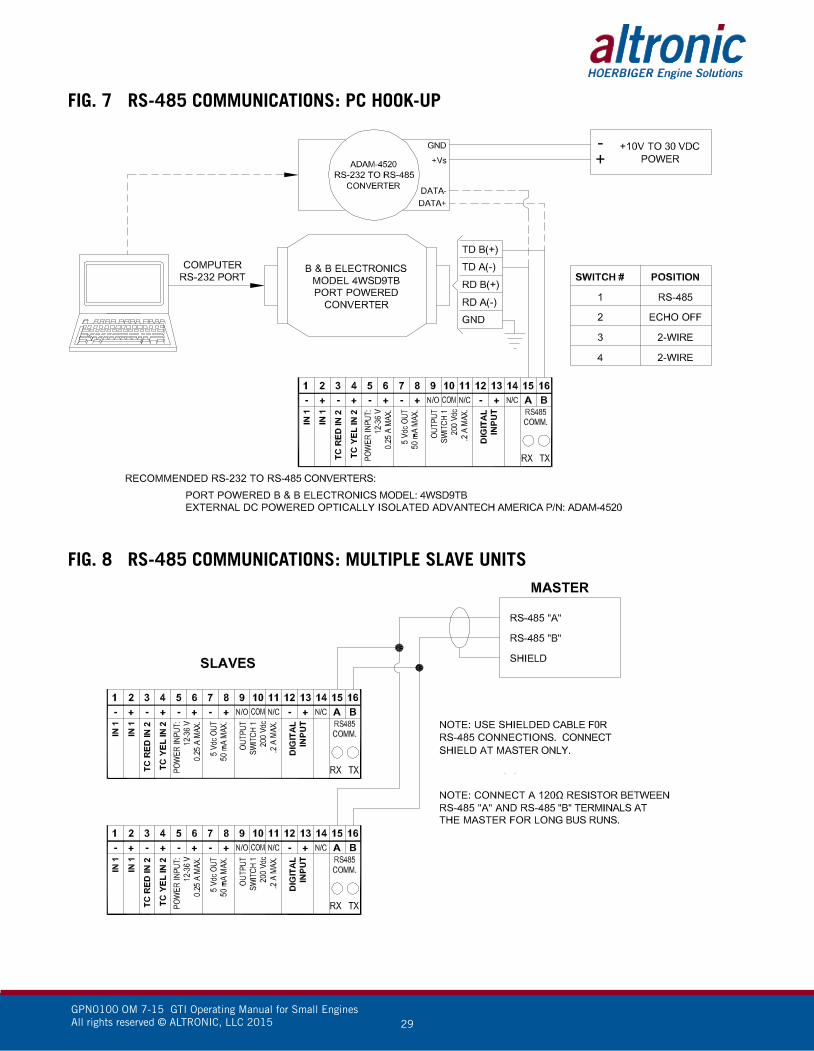
11.7 COMMUNICATIONS WIRING: The RS-485 wiring diagram illustrates the wiring required for multiple slave
unit hookup. Note that every slave unit has a direct connection to the master. This allows any one slave unit to be removed from service without affecting the operation of the other units. Every unit must be programmed with a unique address or node number, but the addition of new units or nodes can be in any order. To minimize unwanted reflections on the transmission line, the bus should be arranged as a trunk line going from one module to the next. Random structures of the transmission line should be avoided. Special care must be taken with long busses (500 feet or more) to ensure error-free operation. Long busses must be terminated with a 120 ohm resistor between the terminals marked RS-485 A and RS-485 B at the master only. The use of twisted pair shielded cable will enhance signal fidelity and is recommended. To prevent ground loops, the shield should be connected to the shield terminal at the master only.
11.8 RX, TX INDICATORS: RX and TX (receive and transmit) LEDs on the back of the gauge indicate when
the unit is receiving or transmitting data.
11.9 CONNECTING TO A PC: When connecting the gauge to the RS-232 port on a PC, an RS-232 to RS-485
converter must be used for the communication interface.
11.10 LOADING: RS-485 uses a balanced differential pair of wires switching from 0 to 5 volts
to communicate data. In situations where many units (32 max.) are connected together on a long run, voltage drop on the communications leads becomes a major problem. Voltage drops on the RS-485 minus lead appear as a common mode voltage to the receivers. While the receivers are rated to a maximum voltage difference of ±7 volts, -7 V to +12 V, a practical system should not have a voltage difference exceeding ±3 volts under normal conditions. The wire gauge used for the connections, therefore, limits the maximum number of units or the maximum length of wire between units in each application. The following formula can be used as a guideline to select the appropriate wire gauge.
For 18 AWG wire No. of units = (4000)/(ft. of wire used) For 20 AWG wire No. of units = (2500)/(ft. of wire used) For 22 AWG wire No. of units = (1600)/(ft. of wire used)
NOTE: The maximum number of units connected in a system is 32.

GPN0100 OM 7-15 GTI Operating Manual for Small Engines All rights reserved © ALTRONIC, LLC 2015 19
12.0 MODBUS REGISTER LISTS The maximum number of registers that can be read at one time is limited to 32.
The maximum number of booleans that can be read at one time is limited to 256. All communications are at 9600 baud (default), see section 10.3 for other speeds 8 Data bits, No Parity, 1 Stop bit (9600 8N1).
12.1 00000 SERIES REGISTERS
ADDRESS DESCRIPTION OF FUNCTION
00001 PROTECT CONFIGURATION 0=OFF 1=ONProtect configuration from being changed by keypad
00002 PROTECT SETPOINT 0=OFF 1=ONProtect setpoints from being changed by keypad
00003 PROTECT COMMUNICATIONS 0=OFF 1=ONProtect against Modbus writes
00004 PROTECT CALIBRATION 0=OFF 1=ONProtect against changing calibration values
00006 CHANNEL 1 RESET MIN/MAX 1=RESETReset MIN/MAX readings for CHANNEL 1
00007 CHANNEL 2 RESET MIN/MAX 1=RESETReset MIN/MAX readings for CHANNEL 2
00008 ↓ ↓00016
RESERVED
00017 SWITCH 1 RESET 1=RESET
00018 ↓ ↓00047
RESERVED
00048 Config Override – Allow Modbus to override Channel Configuration
12.2 10000 SERIES REGISTERS The node number is the address of the controller being contacted. This number
is programmed by the terminal program and can be viewed or edited in the menu screen. A two digit number from 01 to 99 can be used.
ADDRESS DESCRIPTION OF FUNCTION
10001 CHANNEL 1 signal OK 1=OK
10002 CHANNEL 1 signal low out of range 1=LOOR
10003 CHANNEL 1 signal hi out of range 1=HOOR
10004 CHANNEL 1 thermocouple open 1=TCOPEN
10005 ↓ ↓10008
RESERVED
10009 CHANNEL 2 signal OK 1=OK
10010 CHANNEL 2 signal low out of range 1=LOOR
10011 CHANNEL 2 signal hi out of range 1=HOOR
10012 CHANNEL 2 thermocouple open 1=TCOPEN
10013 ↓ ↓10016
RESERVED
10017 SWITCH 1 FAULT HI
10018 SWITCH 1 FAULT LO
10019 ↓ ↓10027
RESERVED
NOTE: All temperatures are stated in 0.1 DEG. Kelvin (for universal compatibility). Therefore a register value of 2730 is 273.0° K, which is 0° C, or 32° F.
NOTE: Consult VSM+ IOM for a complete list of VSM+ Modbus registers.

GPN0100 OM 7-15 GTI Operating Manual for Small Engines All rights reserved © ALTRONIC, LLC 2015 20
12.3 30000 SERIES REGISTERS
ADDRESS DESCRIPTION OF FUNCTION
30001 CHANNEL STATUS – same as 10001–10016
30002 SWITCH STATUS – same as 10017–10032
30004 CHANNEL 1 Analog Value (float msw)
30005 CHANNEL 1 Analog Value (float lsw)
30006 CHANNEL 2 Analog Value (float msw)
30007 CHANNEL 2 Analog Value (float lsw)
30008 RESERVED
30009 RESERVED
30010 Ambient Temp. DEGK (float msw)
30011 Ambient Temp. DEGK (float lsw)
30013 CHANNEL 1 Hi Hyst Timer (0.1s)
30014 CHANNEL 1 Lo Hyst Timer (0.1s)
30015 RESERVED
30016 CHANNEL 2 Hi Hyst Timer (0.1s)
30017 CHANNEL 2 Lo Hyst Timer (0.1s)
30018 RESERVED
30019 CHANNEL 1 MAX (float) (msw)
30020 CHANNEL 1 MAX (float) (lsw)
30021 CHANNEL 1 MIN (float) (msw)
30022 CHANNEL 1 MIN (float) (lsw)
30023 CHANNEL 2 MAX (float) (msw)
30024 CHANNEL 2 MAX (float) (lsw)
30025 CHANNEL 2 MIN (float) (msw)
30026 CHANNEL 2 MIN (float) (lsw)
12.4 40000 SERIES REGISTERS
ADDRESS DESCRIPTION OF FUNCTION
40001 Coils 001-016
40002 Coils 017-032
40003 Coils 033-048
40004 Autoscan 0-30s
40005 Node Number 1-99
40006 Baud rate Index0=9.6k 1=19.2k 2=38.4k 3=57.6k 4=115.2k
40007 Security Password 000-999
40008 Display OptionsBIT 1 RESERVEDBITS 2&3 00=BARGRAPH OFF 01=BARGRAPH ON, SINGLE 10=BARGRAPH ON, INCREMENT SWITCH 2 DIFFERENTIAL BARGRAPH OPTIONSBITS 4&5 00=BARGRAPH OFF 01=BARGRAPH ON, SINGLE 10=BARGRAPH ON, INCREMENT
40009 RESERVED

GPN0100 OM 7-15 GTI Operating Manual for Small Engines All rights reserved © ALTRONIC, LLC 2015 21
ADDRESS DESCRIPTION OF FUNCTION
40010 RESERVED
40011 CHANNEL 1 Lag Filter Gain (1-255)
40012 CHANNEL 1 SENSOR TYPE CUSTOM 0=Custom PRESSURE SENSORS 256=15psi 257=25psi 258=50psi 259=100psi 260=300psi 261=500psi 262=1000psi 263=2000psi 264=5000psI 265=10000psi 266=Custom Pressure TEMPERATURE SENSORS 512=JTC 513=KTC 514=DEG1 515=DEG2 516=Custom Temperature VIBRATION SENSORS Velocity 768=1ips 769=2ips 770=Custom Velocity Acceleration 1024=10g 1025=20g 1026=50g 1027=Custom Acceleration PERCENT 1280=0–100% (0–55Vdc) 1281=Custom Percent VOLTAGE 1536=0–5Vdc 1537=±160mVdc 1538=±80mVdc 1539=Custom Voltage
40013 CHANNEL 1 Units Index (class specific) PRESSURE SENSORS 0=psi 1=psig 2=psia 3=Kpa 4=bar 5=mbar 6=inH2O@20C 7=inHg 8=mmH2O 9=mmHg 10=kg/cm2 11=torr TEMPERATURE SENSORS 0=Kelvin 1=Celsius 2=Fahrenheit VIBRATION SENSORS Velocity 0=in/s 1=mm/s 2=cm/s Acceleration 0=G 1=ft/s/s 2=m/s/s
40014 CHANNEL 1 A/D Voltage Range 0=5V 1=±160mV 2=±80mV
40015 CHANNEL 1 SENSOR MAX (float) (msw)
40016 CHANNEL 1 SENSOR MAX (float) (lsw)
40017 CHANNEL 1 SENSOR MIN (float) (msw)
40018 CHANNEL 1 SENSOR MIN (float) (lsw)
40019 CHANNEL 1 Range HI (float) (msw)
40020 CHANNEL 1 Range HI (float) (lsw)
40021 CHANNEL 1 Volt HI (float) (msw)
40022 CHANNEL 1 Volt HI (float) (lsw)
40023 CHANNEL 1 Range LO (float) (msw)
40024 CHANNEL 1 Range LO (float) (lsw)
40025 CHANNEL 1 Volt LO (float) (msw)
40026 CHANNEL 1 Volt LO (float) (lsw)
40027 CHANNEL 1 Zero Band (float) (msw)
40028 CHANNEL 1 Zero Band (float) (lsw)
40029 CHANNEL 1 Custom Decimal Place (0-4)
40030 CHANNEL 1 Label Index 0=NONE 1=CUSTOM
40031 CHANNEL 1 Custom Label (char. 1:2)
40032 CHANNEL 1 Custom Label (char. 3:4)
40033 CHANNEL 1 Custom Label (char. 5:6)
40034 CHANNEL 1 Custom Label (char. 7:8)
40035 CHANNEL 1 Custom Label(char. 9:10)

GPN0100 OM 7-15 GTI Operating Manual for Small Engines All rights reserved © ALTRONIC, LLC 2015 22
ADDRESS DESCRIPTION OF FUNCTION
40036 CHANNEL 1 Custom Label (char. 11:12)
40037 CHANNEL 1 Custom Label (char. 13:14)
40038 CHANNEL 1 Custom Label (char. 15:16)
40039 CHANNEL 1 Custom Unit Label Index 0=NONE 1=CUSTOM
40040 CHANNEL 1 Custom Unit Label (char. 1:2)
40041 CHANNEL 1 Custom Unit Label (char. 3:4)
40042 CHANNEL 1 Custom Unit Label (char. 5:–)
40043 CHANNEL 1 Bargraph type 0=Off 1=Single bar between low and high 2=Increasing bars between low and high 3=Single bar between setpoints for switch 1 4=Increasing bars between setpoints for switch 1
40044 CHANNEL 1 Bargraph Hi (float) (msw)
40045 CHANNEL 1 Bargraph Hi (float) (lsw)
40046 CHANNEL 1 Bargraph Lo (float) (msw)
40047 CHANNEL 1 Bargraph Lo (float) (lsw)
40048 ↓ ↓40054
RESERVED
40055 CHANNEL 2 Lag Filter Gain (1-255)
40056 CHANNEL 2 SENSOR TYPE CUSTOM 0=Custom PRESSURE SENSORS 256=15psi 257=25psi 258=50psi 259=100psi 260=300psi 261=500psi 262=1000psi 263=2000psi 264=5000psI 265=10000psi 266=Custom Pressure TEMPERATURE SENSORS 512=JTC 513=KTC 514=DEG1 515=DEG2 516=Custom Temperature VIBRATION SENSORS Velocity 768=1ips 769=2ips 770=Custom Velocity Acceleration 1024=10g 1025=20g 1026=50g 1027=Custom Acceleration PERCENT 1280=0–100% (0–55Vdc) 1281=Custom Percent VOLTAGE 1536=0–5Vdc 1537=±160mVdc 1538=±80mVdc 1539=Custom Voltage
40057 CHANNEL 2 Units Index (class specific) PRESSURE SENSORS 0=psi 1=psig 2=psia 3=Kpa 4=bar 5=mbar 6=inH2O@20C 7=inHg 8=mmH2O 9=mmHg 10=kg/cm2 11=torr TEMPERATURE SENSORS 0=Kelvin 1=Celsius 2=Fahrenheit VIBRATION SENSORS Velocity 0=in/s 1=mm/s 2=cm/s Acceleration 0=G 1=ft/s/s 2=m/s/s
40058 CHANNEL 2 A/D Voltage Range 0=5V 1=±160mV 2=±80mV
40059 CHANNEL 2 SENSOR MAX (float) (msw)
40060 CHANNEL 2 SENSOR MAX (float) (lsw)
40061 CHANNEL 2 SENSOR MIN (float) (msw)
40062 CHANNEL 2 SENSOR MIN (float) (lsw)
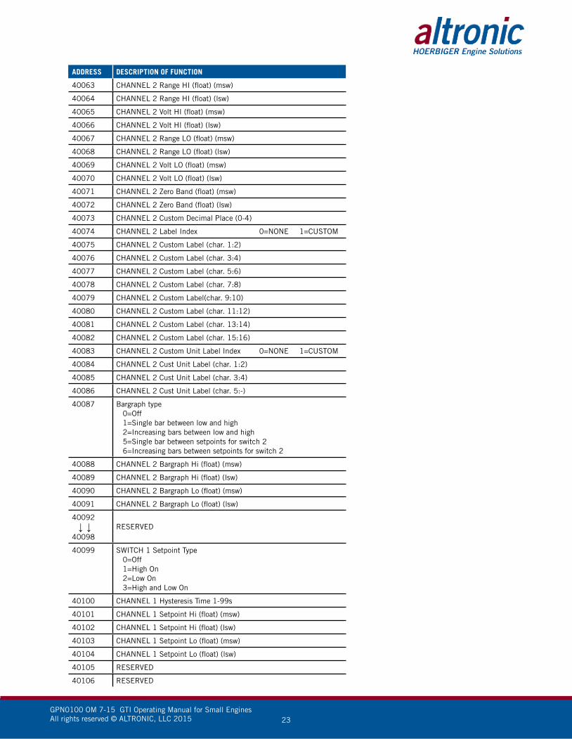
GPN0100 OM 7-15 GTI Operating Manual for Small Engines All rights reserved © ALTRONIC, LLC 2015 23
ADDRESS DESCRIPTION OF FUNCTION
40063 CHANNEL 2 Range HI (float) (msw)
40064 CHANNEL 2 Range HI (float) (lsw)
40065 CHANNEL 2 Volt HI (float) (msw)
40066 CHANNEL 2 Volt HI (float) (lsw)
40067 CHANNEL 2 Range LO (float) (msw)
40068 CHANNEL 2 Range LO (float) (lsw)
40069 CHANNEL 2 Volt LO (float) (msw)
40070 CHANNEL 2 Volt LO (float) (lsw)
40071 CHANNEL 2 Zero Band (float) (msw)
40072 CHANNEL 2 Zero Band (float) (lsw)
40073 CHANNEL 2 Custom Decimal Place (0-4)
40074 CHANNEL 2 Label Index 0=NONE 1=CUSTOM
40075 CHANNEL 2 Custom Label (char. 1:2)
40076 CHANNEL 2 Custom Label (char. 3:4)
40077 CHANNEL 2 Custom Label (char. 5:6)
40078 CHANNEL 2 Custom Label (char. 7:8)
40079 CHANNEL 2 Custom Label(char. 9:10)
40080 CHANNEL 2 Custom Label (char. 11:12)
40081 CHANNEL 2 Custom Label (char. 13:14)
40082 CHANNEL 2 Custom Label (char. 15:16)
40083 CHANNEL 2 Custom Unit Label Index 0=NONE 1=CUSTOM
40084 CHANNEL 2 Cust Unit Label (char. 1:2)
40085 CHANNEL 2 Cust Unit Label (char. 3:4)
40086 CHANNEL 2 Cust Unit Label (char. 5:-)
40087 Bargraph type 0=Off 1=Single bar between low and high 2=Increasing bars between low and high 5=Single bar between setpoints for switch 2 6=Increasing bars between setpoints for switch 2
40088 CHANNEL 2 Bargraph Hi (float) (msw)
40089 CHANNEL 2 Bargraph Hi (float) (lsw)
40090 CHANNEL 2 Bargraph Lo (float) (msw)
40091 CHANNEL 2 Bargraph Lo (float) (lsw)
40092 ↓ ↓40098
RESERVED
40099 SWITCH 1 Setpoint Type 0=Off 1=High On 2=Low On 3=High and Low On
40100 CHANNEL 1 Hysteresis Time 1-99s
40101 CHANNEL 1 Setpoint Hi (float) (msw)
40102 CHANNEL 1 Setpoint Hi (float) (lsw)
40103 CHANNEL 1 Setpoint Lo (float) (msw)
40104 CHANNEL 1 Setpoint Lo (float) (lsw)
40105 RESERVED
40106 RESERVED

GPN0100 OM 7-15 GTI Operating Manual for Small Engines All rights reserved © ALTRONIC, LLC 2015 24
ADDRESS DESCRIPTION OF FUNCTION
40107 RESERVED
40108 CHANNEL 2 Hysteresis Time 1-99s
40109 CHANNEL 2 Setpoint Hi (float) (msw)
40110 CHANNEL 2 Setpoint Hi (float) (lsw)
40111 CHANNEL 2 Setpoint Lo (float) (msw)
40112 CHANNEL 2 Setpoint Lo (float) (lsw)
40113 RESERVED
40114 RESERVED
GPN0100 OM 7-15 GTI Operating Manual for Small Engines All rights reserved © ALTRONIC, LLC 2015 25
FIG. 1 MOUNTING DIMENSIONS
13.21335.5
11.34287.9
12.05306
13.34338.9
4.28108.8
4.28108.8
3.9099.1
7.28185
8.30
210.8
.246.2
2.7670
.88 22.2 THRU1.06 26.9 THRU
FIG.6 MOUNTING DIMENSION GPN0100/GPN0100-12 WITH VSM+
SK21436-22-15WTP

GPN0100 OM 7-15 GTI Operating Manual for Small Engines All rights reserved © ALTRONIC, LLC 2015 26
FIG. 2 WIRING DIAGRAM, CUSTOMER CONNECTIONS
1k OHM Resistor
FIG. 3 CUSTOMER WIRING, VSM+
Customer Wiring Harness 693134-X

GPN0100 OM 7-15 GTI Operating Manual for Small Engines All rights reserved © ALTRONIC, LLC 2015 27
FIG. 4 FLOW CHART
AUTOSCAN XXå
QUICK START-UP
~CHANNEL 1
CHANNEL 2
COMMUNICATIONS
SECURITY
CHANNEL 1
UNITS PSI
~FILTER 230
SETPOINTS
CONFIGURE
CALIBRATE
RESET
PREVIOUS MENU
SWITCH 1
~HI 25.0 psig
LO OFF
HYST. 3 SEC.
PREVIOUS MENU
CHANNEL 1
CONFIGURE
~TYPE
GAUGE LABEL
BARGRAPH
PREVIOUS MENU
CHANNEL 1
CALIBRATE:
~FULL CAL
TWEAK LO ONLY
TWEAK HI ONLY
RECALL FACT CAL
PREVIOUS MENU
CHANNEL 1
RESET:
~MIN/MAX READING
PREVIOUS MENU
CHANNEL 1
SELECT TYPE:
éPRESSURE
SELECT RANGE:
50 PSI
APPLY CANCEL
COMMUNICATIONS:
~NODE: 1
BAUD: 9600
PREVIOUS MENU
SECURITY:
CONFIG PROT ON
SETPNT PROT ON
COMM PROT ON
CAL PROT ON
~PASSWORD 000
PREVIOUS MENU
CHANNEL 1
GAUGE LABEL:
éINDEX: 5
MANIFLD AIR PRES
PREVIOUS MENU
CHANNEL 1
FACTORY CAL:
TYPE:
PRESSURE
RANGE:
50psi
CANCEL ~APPLY
CHANNEL 1
BARGRAPH:
éSINGLE BAR
0%
XX.X psi
100%
XX.X psi
PREVIOUS MENU
CHANNEL 1
CALIBRATE:
SET HI POINT
ON CALIBRATOR
AND PRESS ENTER
CALIBRATION
VALUES SAVED!
CHANNEL 1
CALIBRATE:
ADJUST HI
POINT TO MATCH
CALIBRATOR
éXX.X psi
BI-FUEL ON
MANIFLD AIR PRES
22.5
CH1 psig
CH2 850 °F
AN
Y H
OM
E S
CR
EE
N
ENTE
R
MEN
UES
C
ENTE
R
ENTE
REN
TER
ENTE
R
ENTE
REN
TER
ENTE
R
ENTE
R
ENTE
R
ENTE
R
ENTE
R
ENTE
R
ENTE
R
ENTE
R
ENTE
R
CHANNEL 1
CALIBRATE:
ADJUST LO
POINT TO MATCH
CALIBRATOR
éXX.X psi
CHANNEL 1
CALIBRATE:
SET LO POINT
ON CALIBRATOR
AND PRESS ENTER
NO
TE
S:
1. T
O M
AK
E A
CH
AN
GE
, US
E T
HE
UP
( Ç) O
R D
OW
N ( ü
) AR
RO
W
KE
Y T
O P
OIN
T T
O T
HE
ITE
M T
O B
E C
HA
NG
ED
. WH
EN
TH
E ( ~
) A
RR
OW
PO
INT
S T
O T
HE
ITE
M, P
RE
SS
EN
TE
R. T
HE
AR
RO
W
WIL
L C
HA
NG
E T
O T
HE
SC
RO
LL ( é
) SY
MB
OL.
US
E T
HE
UP
OR
D
OW
N A
RR
OW
KE
YS
TO
SC
RO
LL, T
HE
N P
RE
SS
EN
TE
R.
“SA
VE
D”
WIL
L B
E D
ISP
LAY
ED
ON
TH
E L
INE
FO
R O
NE
SE
CO
ND
, T
HE
N T
HE
LIN
E W
ILL
RE
TU
RN
WIT
H T
HE
NE
W V
ALU
E.
2. U
SE
TH
E M
EN
U/E
SC
KE
Y T
O E
XIT
AN
Y M
EN
U A
ND
RE
TU
RN
TO
T
HE
HO
ME
SC
RE
EN
.
3. C
HA
NN
EL
2 P
ATH
IS T
HE
SA
ME
AS
CH
AN
NE
L 1.
CHANNEL 1
UNITS PSI
FILTER 230
~SETPOINTS
CONFIGURE
CALIBRATE
RESET
PREVIOUS MENU
CHANNEL 1
UNITS PSI
FILTER 230
SETPOINTS
~CONFIGURE
CALIBRATE
RESET
PREVIOUS MENU
CHANNEL 1
UNITS PSI
FILTER 230
SETPOINTS
CONFIGURE
~CALIBRATE
RESET
PREVIOUS MENU
CHANNEL 1
UNITS PSI
FILTER 230
SETPOINTS
CONFIGURE
CALIBRATE
~RESET
PREVIOUS MENU
AUTOSCAN XXå
QUICK START-UP
CHANNEL 1
CHANNEL 2
~COMMUNICATIONS
SECURITY
AUTOSCAN XXå
QUICK START-UP
CHANNEL 1
CHANNEL 2
COMMUNICATIONS
~SECURITY
AUTOSCAN XXå
~QUICK START-UP
CHANNEL 1
CHANNEL 2
COMMUNICATIONS
SECURITY
QUICK START MENU
~UNITS ENGLISH
FUEL DELAY 60s
PREVIOUS MENU

GPN0100 OM 7-15 GTI Operating Manual for Small Engines All rights reserved © ALTRONIC, LLC 2015 28
FIG. 5 LADDER LOGIC
FIG. 6 GPN0100 CHANNEL DESCRIPTION CHART
Channel DescriptionDisplayed Units
(Default: English)Displayed Units
(Metric)Default Control Setpoints Default Safety Setpoints
Low High Low High
1 MAP psig Kpa 20 55 — —
2 EGT °F °C — — – 76 1476
GPN0100 OM 7-15 GTI Operating Manual for Small Engines All rights reserved © ALTRONIC, LLC 2015 29
FIG. 7 RS-485 COMMUNICATIONS: PC HOOK-UP
FIG. 8 RS-485 COMMUNICATIONS: MULTIPLE SLAVE UNITS