Embed Size (px)
Citation preview

Operating Manual
SI251 SinCos interpolator for encoders and measuring systems with SinCos output
Product features:
Converts 1 Vpp standard sinus wave signals into incremental square wave signals
Outputs A, /A, B, /B, Z, /Z (RS422 / TTL) and A, B, Z (18 … 30 V HTL)
Adjustable multiplier for interpolation rates from 1 : 5 … 1 : 50
Adjustable divider 1 : 1 … 1 : 128 to reduce the output frequency
Sinus-input frequency 0 … 400 kHz
Quadrature output frequency up to 4 MHz
Adjustable glitch filter
Power supply 18 … 30 VDC
3046 Home Road. Powell, OH 43065 P: (740) 917-5781 F: (740) 917-5791 www.GenesisAutomationOnline.com [email protected]
www.GenesisAutomationOnline.com

Si251_01c_oi_e.doc / Apr-16 Page 2 / 17
Version: Description:
SI25101a/ AF/ Nov. 04 Original
SI25101b/ AF/HK/ Feb.05 Corrections with connectors male/female, DIL2 settings and
miscellaneous small bugs
Si25101c_oi/Jun-15/ag „Safety Instructions“ and „Technical Specifications“ new.
„Legal notices“ supplemented and manual-design updated.
Legal notices:
All contents included in this manual are protected by the terms of use and copyrights of motrona GmbH.
Any reproduction, modification, usage or publication in other electronic and printed media as well as in
the internet requires prior written authorization by motrona GmbH.
Table of Contents
1. Safety Instructions and Responsibility ........................................................ 3
1.1. General Safety Instructions ................................................................................... 3
1.2. Use according to the intended purpose ................................................................ 3
1.3. Installation ............................................................................................................. 4
1.4. Cleaning, Maintenance and Service Notes ........................................................... 4
2. Introduction ................................................................................................ 5
3. Block Diagram ............................................................................................. 6
4. Connections ................................................................................................ 7
4.1. Connection overview ............................................................................................. 8
5. Pin assignment of SUB-D-connectors .......................................................... 9
5.1. Sin/Cos inputs ....................................................................................................... 9
5.2. RS 422 impulse output ........................................................................................ 10
6. Switch settings ......................................................................................... 11
7. Frequency Divider and Error Signals .......................................................... 14
8. Delays....................................................................................................... 15
9. Miscellaneous Hints ................................................................................. 15
10. Dimensions ............................................................................................... 16
11. Technical Specifications ........................................................................... 17

Si251_01c_oi_e.doc / Apr-16 Page 3 / 17
1. Safety Instructions and Responsibility
1.1. General Safety Instructions This operation manual is a significant component of the unit and includes important rules and
hints about the installation, function and usage. Non-observance can result in damage and/or
impairment of the functions to the unit or the machine or even in injury to persons using the
equipment!
Please read the following instructions carefully before operating the device and observe all
safety and warning instructions! Keep the manual for later use.
A pertinent qualification of the respective staff is a fundamental requirement in order to use
these manual. The unit must be installed, connected and put into operation by a qualified
electrician.
Liability exclusion: The manufacturer is not liable for personal injury and/or damage to property
and for consequential damage, due to incorrect handling, installation and operation. Further
claims, due to errors in the operation manual as well as misinterpretations are excluded from
liability.
In addition the manufacturer reserve the right to modify the hardware, software or operation
manual at any time and without prior notice. Therefore, there might be minor differences
between the unit and the descriptions in operation manual.
The raiser respectively positioner is exclusively responsible for the safety of the system and
equipment where the unit will be integrated.
During installation or maintenance all general and also all country- and application-specific
safety rules and standards must be observed.
If the device is used in processes, where a failure or faulty operation could damage the system
or injure persons, appropriate precautions to avoid such consequences must be taken.
1.2. Use according to the intended purpose The unit is intended exclusively for use in industrial machines, constructions and systems. Non-
conforming usage does not correspond to the provisions and lies within the sole responsibility
of the user. The manufacturer is not liable for damages which has arisen through unsuitable
and improper use.
Please note that device may only be installed in proper form and used in a technically perfect
condition (in accordance to the Technical Specifications, see chapter 11). The device is not
suitable for operation in explosion-proof areas or areas which are excluded by the EN 61010-1
standard.

Si251_01c_oi_e.doc / Apr-16 Page 4 / 17
1.3. Installation The device is only allowed to be installed and operated within the permissible temperature
range. Please ensure an adequate ventilation and avoid all direct contact between the device
and hot or aggressive gases and liquids.
Before installation or maintenance, the unit must be disconnected from all voltage-sources.
Further it must be ensured that no danger can arise by touching the disconnected voltage-
sources.
Devices which are supplied by AC-voltages, must be connected exclusively by switches,
respectively circuit-breakers with the low voltage network. The switch or circuit-breaker must
be placed as near as possible to the device and further indicated as separator.
Incoming as well as outgoing wires and wires for extra low voltages (ELV) must be separated
from dangerous electrical cables (SELV circuits) by using a double resp. increased isolation.
All selected wires and isolations must be conform to the provided voltage- and temperature-
ranges. Further all country- and application-specific standards, which are relevant for structure,
form and quality of the wires, must be ensured. Indications about the permissible wire cross-
sections for wiring are described in the Technical Specifications (see chapter 11).
Before first start-up it must be ensured that all connections and wires are firmly seated and
secured in the screw terminals. All (inclusively unused) terminals must be fastened by turning
the relevant screws clockwise up to the stop.
Overvoltages at the connections must be limited to values in accordance to the overvoltage
category II.
For placement, wiring, environmental conditions as well as shielding and earthing/grounding of
the supply lines the general standards of industrial automation industry and the specific
shielding instructions of the manufacturer are valid. Please find all respective hints and rules on
www.motrona.com/download.html --> “[General EMC Rules for Wiring, Screening and
Earthing]”.
1.4. Cleaning, Maintenance and Service Notes To clean the front of the unit please use only a slightly damp (not wet!), soft cloth. For the rear
no cleaning is necessary. For an unscheduled, individual cleaning of the rear the maintenance
staff or assembler is self-responsible.
During normal operation no maintenance is necessary. In case of unexpected problems, failures
or malfunctions the device must be shipped for back to the manufacturer for checking,
adjustment and reparation (if necessary). Unauthorized opening and repairing can have
negative effects or failures to the protection-measures of the unit.

Si251_01c_oi_e.doc / Apr-16 Page 5 / 17
2. Introduction SI251 represents an encoder interface unit, designed to convert output signals of so-called
“sine-cosine-encoders” and similar measuring systems into incremental quadrature impulse
signals.
Under consideration of an adjustable multiplier the unit interpolates a corresponding number of
impulses from every sine wave. An additional programmable divider provides division of the
impulses if applicable, before they appear at the output. Impulses are available with TTL/RS422
standard (A, /A, B, /B, Z, /Z) and with HTL standard (A, B, Z, 18 … 30 V) at the same time.
SI251 also possesses a selectable glitch filter to minimize interferences on the signal lines. The
maximum sine input frequency is 400 kHz. The interpolation rate can be set in a range from 5 to
50, i.e. the unit can generate up to 50 pulses from one sine period.
The maximum output frequency is 4 MHz with use of the RS422 output, and approx. 100 kHz
when the HTL output is used. Where applicable, the output frequency can be reduced by a
selectable divider 1 : 1 … 1 : 128.
Independent of the selected interpolation rate, an interpolation time can be set in order to limit
the output frequency to a desired maximum value.
The unit provides auxiliary output voltages of 5.2 volts and approx. 20 volts, all short-circuit-
proofed, for power supply of the sine/cosine encoder.
Errors will be indicated by a LED and at the same time by a digital control output. Errors can be
reset by means of a pushbutton on the unit, or by a remote reset signal.
All settings are done by means of two DIL switches which are accessible from the top site and
the bottom site of the housing.
The mechanical construction provides a compact housing for rail mounting, with
12 screw terminals and two SUB-D-connectors

Si251_01c_oi_e.doc / Apr-16 Page 6 / 17
3. Block Diagram
/A ,/B, /Z, A, B, Z
SIN-
COS+
COS-
REF-
SIN+
REF+
3
2
8
Vdd = 20 V / 150 mA
Vcc = 5.2V / 150 mA
1Encoder Supply
A 1011
9
12
B
ZJum
per
5
6 GND
+Power
+
-
/A
B
/B
/Z
A
Z

Si251_01c_oi_e.doc / Apr-16 Page 7 / 17
4. Connections The unit provides a 9-pin SUB-D connector (female on the unit site) for connection of the SinCos
sensor. For easy power supply of the encoder, an external jumper allows to switch an auxiliary
voltage of either 5.2 V or approx. 20 V to the same connector. Also the mean voltage is
available on the connector pins, allowing also the use of sensors with non-differential sinus
output.
The incremental output impulses are available with RS422 standard and HTL standard (push-
pull) at the same time, and one output of both or both outputs at a time may be used, quite
according to the application.
All inputs and outputs as well as the power supply refer to the same
reference potential (GND)!
In case of errors the Error Output switches to HIGH. At the same time the yellow front LED will
be lit. To release an Error state, a HIGH signal must be applied to the “Error Release” input
(PNP, HTL, a positive signal of 10 … 30 VDC will release the error). Errors may be cleared also
by pushing the small button on the top site of the unit.
The unit operates with a 18 … 30 VDC power applied to terminals 5 (+) and 6 (-)

Si251_01c_oi_e.doc / Apr-16 Page 8 / 17
4.1. Connection overview
mal
e
fem
ale
Test
Erro
r O
ut
Erro
r re
leas
e
18
-30
V
GN
D
A (H
TL)
Encoder supply
5.2V
VD
D
DIL-switch 1 iImpulse divider)
Pushbutton and DIL switch 2 (Configuration)
B (H
TL)
Z (H
TL)
GN
D
LED’s
At any time, the over-all transmission characteristics of encoder, external components and
capacity of cable must ensure proper signals at the input of the unit, with respect to levels,
shape and phase displacement A/B.
The output swing of the HTL push-pull outputs corresponds to the input supply voltage on
terminals 5 and 6.
Si251_01c_oi_e.doc / Apr-16 Page 9 / 17
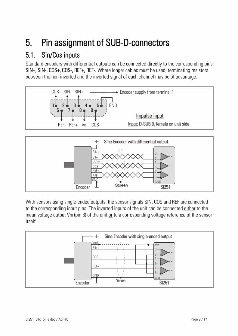
5. Pin assignment of SUB-D-connectors
5.1. Sin/Cos inputs Standard encoders with differential outputs can be connected directly to the corresponding pins
SIN+, SIN-, COS+, COS-, REF+, REF-. Where longer cables must be used, terminating resistors
between the non-inverted and the inverted signal of each channel may be of advantage.
COS+ SIN- SIN+
GND
REF- REF+ COS-
1 2 3 4 5986 7
Vm
Encoder supply from terminal 1
SIN+
SIN-COS+
COS-REF+
REF-
3
21
97
6
GNDGND
With sensors using single-ended outputs, the sensor signals SIN, COS and REF are connected
to the corresponding input pins. The inverted inputs of the unit can be connected either to the
mean voltage output Vm (pin 8) of the unit or to a corresponding voltage reference of the sensor
itself
SIN+
COS+
REF+
3
21
97
6
GNDGND
Vm1Vm2

Si251_01c_oi_e.doc / Apr-16 Page 10 / 17
When the reference signals REF+ and REF- are not used or not available, the related inputs of
the converter must be tied to a defined potential.
When connecting the REF- pin to Vm with the REF+ pin open, the unit will generate a Z impulse
with every sine period.
When connecting the REF+ pin to Vm with the REF- pin open, the unit will not generate a Z
impulse.
The sine-cosine signals on the input site are highly sensitive analogue
signals! Therefore it is mandatory to use proper screening. Use of cables
with pair wise twisted leads is highly recommended. The cable length
should not exceed 5 meters if possible.
With critical applications, a terminating impedance (approx. 470 ohms,
and where required a capacitor of 680 pF to 4.7 nF) connected between
the differential inputs may be helpful.
5.2. RS 422 impulse output
B/AA
GND
/ZZ/B
123459 8 67

Si251_01c_oi_e.doc / Apr-16 Page 11 / 17
6. Switch settings Switch DIL1 allows to set the filter and to choose the interpolation rate and interpolation time.
Switch DIL2 selects a programmable divider and allows to set the unit to test mode
Changes of the DIL switch positions will become active only after the
next power-up of the unit!
DIL1: ( 0 = OFF, 1 = ON ) Interpolation and Filtering
8 7 6 5 4 3 2 1
1 1 Minimum Filter
Filtering
1 0 Filter 10 kHz
0 1 Filter 100 kHz
1 Glitch-Filter OFF
0 Glitch-Filter ON
1 1 1 40
Interpolation rate
1 1 0 20
1 0 1 10
1 0 0 5
0 1 1 50
0 1 0 25
0 0 1 12,5
0 0 0 6,25
1 1 25 ns
Interpolation time 1 0 100 ns
0 1 400 ns
0 0 1600 ns

Si251_01c_oi_e.doc / Apr-16 Page 12 / 17
Hints for settings of DIL switch 1:
Under proper electrical conditions there is no imperative need to use the
filtering functions offered in the table above. When you set your
interpolation factor with use of the filter settings highlighted in the
table, there will be no further restrictions with the operating range of
the unit.
se of the filtering functions will eliminate noise on the signal lines, but
at the same time result in some limitations and restrictions of the
operating range. The sine input frequency must not exceed the selected
filter frequency. Where you decide to use the 100 kHz filter, the unit will
not respond to frequencies higher than 100 kHz.
Distortions of the input signal result in fluctuation of the output
frequency.
Use of the glitch filter results in increased interpolation times at
standstill or with low input frequencies, therefore reduces noise and
jitter of the output signal by a few increments up and down in standstill.
However, when the glitch filter is switched on, fast changes of the
speed can result in temporary proportional errors between input
frequency and output frequency during acceleration
The subsequent table shows the limits of input and output frequencies with respect to the DIL
switch settings:
Interpolation rate Interpolation time Maximum output
frequency
Maximum input
frequency
x5
25 ns 2 MHz 400 kHz
100 ns 2 MHz 400 kHz
400 ns 625 kHz 125 kHz
1600 ns 156.25 kHz 31.25 kHz
x6,25
25 ns 2,5 MHz 400 kHz
100 ns 2,5 MHz 400 kHz
400 ns 625 kHz 100 kHz
1600 ns 156.25 kHz 25 kHz
x10
25 ns 4 MHz 400 kHz
100 ns 2,5 MHz 250 kHz
400 ns 625 kHz 62.5 kHz
1600 ns 156.25 kHz 15.625 kHz

Si251_01c_oi_e.doc / Apr-16 Page 13 / 17
Interpolation rate Interpolation time Maximum output
frequency
Maximum input
frequency
x12,5
25 ns 4 MHz 320 kHz
100 ns 2.5 MHz 200 kHz
400 ns 625 kHz 50 kHz
1600 ns 156.25 kHz 12.5 kHz
x20
25 ns 4 MHz 200 kHz
100 ns 2.5 MHz 125 kHz
400 ns 625 kHz 31.25 kHz
1600 ns 156.25 kHz 7.8125 kHz
x25
25 ns 4 MHz 160 kHz
100 ns 2.5 MHz 100 kHz
400 ns 625 kHz 25 kHz
1600 ns 156.25 kHz 6.25 kHz
x40
25 ns 4 MHz 100 kHz
100 ns 2.5 MHz 62.5 kHz
400 ns 625 kHz 15.625 kHz
1600 ns 156.25 kHz 3.90625 kHz
x50
25 ns 4 MHz 80 kHz
100 ns 2.5 MHz 50 kHz
400 ns 625 kHz 12.5 kHz
1600 ns 156.25 kHz 3.125 kHz

Si251_01c_oi_e.doc / Apr-16 Page 14 / 17
7. Frequency Divider and Error Signals The programmable frequency divider provides decrease of the output frequency by an
adjustable division rate between 1 : 1 and 1 : 128.
The following errors are detected and indicated by the yellow LED and the Error output:
Wire break with one of the signals SIN+, SIN-, COS+ or COS-
Too low amplitude on one of above signal lines
The input frequency exceeds it’s maximum level, the output frequency is unable to
follow
The signals REF+ and REF- are not subject of the error check procedure. Depending on
the settings on the DIL2 switch, error signals remain active until remote
acknowledgement, or reset automatically upon elimination of the error.
In case of an error the proper function of the unit is not ensured and a loss of encoder
pulses can occur.
DIL2: ( 0 = OFF, 1 = ON ) Divider and testing functions
8 7 6 5 4 3 2 1
1 1 1 1 1 1 1 : 2
Division rate
1 1 1 1 1 0 1 : 4
1 1 1 1 0 1 1 : 6
1 1 1 1 0 0 1 : 8
1 1 1 0 1 1 1 : 10
1 1 1 0 1 0 1 : 12
1 1 1 0 0 1 1 : 14
1 1 1 0 0 0 1 : 16
1 1 0 1 1 1 1 : 18
- - - - - - - - - - - - - - - - - - - - - -
0 0 0 0 0 0 1 : 128
1 Automatic error reset Error LED and output
0 Static error message
0 Divider switched on Divider
1 Divider switched off

Si251_01c_oi_e.doc / Apr-16 Page 15 / 17
8. Delays There is a delay time between the analogue input signals and the incremental output signals,
which is typically 3 µsec. when the divider is switched off. Use of the divider function will
extend the delay time correspondingly. The delay time is constant, and causes a frequency
dependent phase shift between the input and output signals.
9. Miscellaneous Hints The unit will reach full accuracy only after a transient period of approximately 20 full
sine cycles at the input. Before that, the input frequency should not exceed about 50 %
of the normal maximum frequency
The application of digital interpolation procedures requires use of quantization steps,
which can cause a certain dither of the output signal.
The quality of the output signal depends essentially on the input signals. Therefore
maximum elaborateness is recommended with screening, running of cables and cable
length.
SI251 does not possess a potential separation, i.e. the unit GND is at the same time
also GND of the sensor. Therefore it is important to ensure clear conditions with
earthing and to prevent earth loops and balance currents flowing through the unit.
Where unrulable potential situations should come up, it is recommended to use a fully
separate power supply for the SI 251 unit

Si251_01c_oi_e.doc / Apr-16 Page 16 / 17
10. Dimensions
40 mm (1.575’’)
79 m
m (3
.110
’’)
74 mm (2.193’’)
91mm (3.583’’)
Front view Side view

Si251_01c_oi_e.doc / Apr-16 Page 17 / 17
11. Technical Specifications
Power supply: Input voltage:
Protection circuit:
Ripple:
Consumption:
Connections:
18 … 30 VDC
reverse polarity protection
≤ 10 % at 24 VDC
approx. 150 mA at 18 V / approx. 90 mA at 30 V
(without external load)
screw terminal, 1.5 mm² / AWG 16
Encoder supply: Number of aux. Voltages:
Encoder supply 1:
Encoder supply 2:
Output current:
Connections:
2
+ 5.2 VDC
power supply (Vdd) minus 4 VDC
each max. 150 mA
screw terminal, 1.5 mm² / AWG 16
SinCos input: Amplitude:
DC offset:
Channels:
Frequency:
Differential REF-input signal:
Connections:
min. 0.8 Vpp … max.1.2 Vpp
min. 1.8 V … max. 3.1 V
SIN+, SIN-, COS+, COS-, REF+, REF-
max. 400 kHz
HIGH 130 mV, LOW 40 mV
SUB-D (female), 9-pin
„Error Release“ input: Signal levels:
Internal resistance:
Connections:
10 … 30 V, HTL / PNP,
LOW: 0 … 4 V, HIGH: 10 … 30 V
Ri ≈ 10 kOhm
screw terminal, 1.5 mm² / AWG 16
Incremental output
HTL:
Signal level:
Channels:
Output current:
Connections:
power supply (Vdd) minus 4 VDC
A, B, Z (push-pull)
max. 40 mA
screw terminal, 1.5 mm² / AWG 16
Incremental output
TTL / RS422:
Signal levels:
Channels:
Frequency:
Connections:
5 VDC
A, /A, B, /B, Z, /Z
up to 4 MHz
SUB-D (male), 9-pin
„Error“ output Signal level:
Output current:
Connections:
HTL, power supply (Vdd) minus 4 VDC
max. 40 mA
screw terminal, 1.5 mm² / AWG 16
Housing: Material:
Mounting:
Dimensions (w x h x d):
Protection class:
Weight:
plastic
35 mm top hat rail (according to EN 60715)
40 x 79 x 91 mm / 1.5748 x 3.1102 x 3.5827 inch
IP20
approx. 200 g
Ambient temperature: Operation:
Storage:
0 °C … +45 °C / +32 … +113 °F (not condensing)
-25 °C … +70 °C / -13 … +158 °F (not condensing)
Failure rate: MTBF in years: 40.2 a (long-term usage at 60 °C / 140 °F )
Conformity and
standards:
EMC 2004/108/EC:
Guideline 2011/65/EU:
EN 61000-6-2, EN 61000-6-3, EN 61000-6-4
RoHS-conform
3046 Home Road. Powell, OH 43065 P: (740) 917-5781 F: (740) 917-5791 www.GenesisAutomationOnline.com [email protected]