Embed Size (px)
Citation preview

Operating Manual for
Model 34988Recovery, Recycling, Recharging Unit
SAFETY DEFINITIONS: Follow all WARNING, CAUTION, and NOTE messages in this manual. These messages are defined as follows: WARNING means you may risk serious personal injury or death; CAUTION means you may risk personal injury, property damage, or unit damage; and NOTEs and OPERATING TIPS provide clarity and helpful information. These safety messages cover situations ROBINAIR is aware of. ROBINAIR cannot know, evaluate, and advise you as to all possible hazards. You must verify that conditions and procedures do not jeopardize your personal safety.
DISCLAIMER: Information, illustrations, and specifications contained in this manual are based on the latest information available at the time of publication. The right is reserved to make changes at any time without obligation to notify any person or organization of such revisions or changes. Further, ROBINAIR shall not be liable for errors contained herein or for incidental or consequential damages (including lost profits) in connection with the furnishing, performance, or use of this material. If necessary, obtain additional health and safety information from the appropriate government agencies and the vehicle, refrigerant, and lubricant manufacturers.
ALLOW ONLY QUALIFIED PERSONNEL TO OPERATE THE UNIT. Before operating the unit, read and follow the instructions and warnings in this manual. The operator must be familiar with air conditioning and refrigeration systems, refrigerants, and the dangers of pressurized components. If the operator cannot read this manual, operating instructions and safety precautions must be read and discussed in the operator’s native language.
PRESSURIZED TANK CONTAINS LIQUID REFRIGERANT. Do not overfill the internal storage vessel, because overfilling may cause explosion and personal injury or death. Do not recover refrigerants into nonrefillable containers; use only federally authorized refillable containers (DOT spec. 4BW or 4BA).
HOSES MAY CONTAIN LIQUID REFRIGERANT UNDER PRESSURE. Contact with refrigerant may cause personal injury. Wear protective equipment, including safety goggles. Disconnect hoses using extreme caution.
AVOID BREATHING A/C REFRIGERANT AND LUBRICANT VAPOR OR MIST. Exposure may irritate eyes, nose, and throat. To remove refrigerant from the A/C system, use only equipment certified for the type of refrigerant being removed. Use the unit in locations with mechanical ventilation that provides at least four air changes per hour. If accidental system discharge occurs, ventilate the work area before resuming service.
DO NOT USE AN EXTENSION CORD. An extension cord may overheat and cause fire. If you must use an extension cord, use the shortest possible cord with a minimum size of 14 AWG.
TO REDUCE THE RISK OF FIRE, do not use the unit in the vicinity of spilled or open containers of gasoline or other flammable substances.
CAUTION—DO NOT PRESSURE TEST OR LEAK TEST EQUIPMENT AND / OR VEHICLE AIR CONDI-TIONING SYSTEMS WITH COMPRESSED AIR. Some mixtures of air and refrigerant have been shown to be combustible at elevated pressures. These mixtures, if ignited, may cause injury or property damage.
TO PREVENT CROSS-CONTAMINATION, USE THIS UNIT WITH R-134A REFRIGERANT ONLY. The unit is designed to recover, recycle, and recharge only R-134a refrigerant. Do not attempt to adapt the unit for another refrigerant. Do not mix refrigerant types through a system or in the same container; mixing of refrigerants will cause severe damage to the unit and the vehicle air conditioning system.
HIGH VOLTAGE ELECTRICITY INSIDE THE UNIT HAS A RISK OF ELECTRICAL SHOCK. Exposure may cause personal injury. Disconnect the power before servicing the unit.
Additional health and safety information may be obtained from the refrigerant and lubricant manufacturers.
WARNINGS
Model 34988Recovery, Recycling, & Recharging Unit
OPERATING NOTE: At temperatures exceeding 120° F / 49° C, wait 10 minutes between recovery jobs.
1554228 Rev. E July 30, 2013
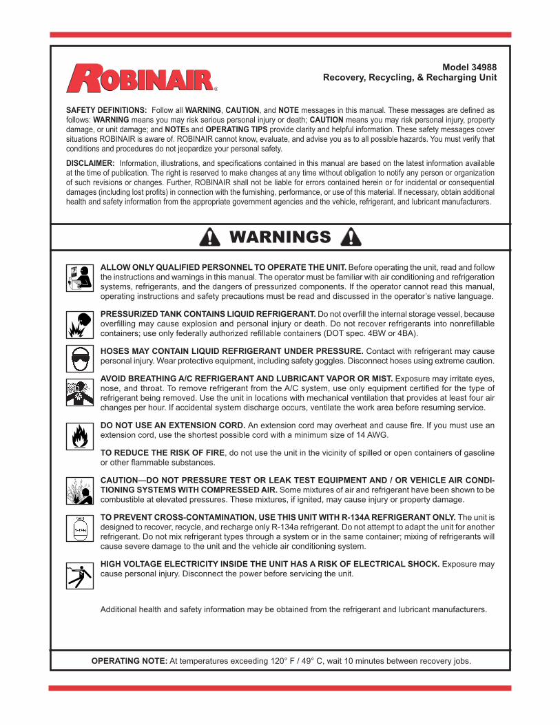
Table of Contents
Introduction TechnicalSpecifications . . . . . . . . . . . . . . . . . . . . . . . . . . . . . . . . 2 ControlPanelFunctions . . . . . . . . . . . . . . . . . . . . . . . . . . . . . . . . 3 Glossary . . . . . . . . . . . . . . . . . . . . . . . . . . . . . . . . . . . . . . . . . . . . 3 MenuFunctions . . . . . . . . . . . . . . . . . . . . . . . . . . . . . . . . . . . . . . 4Setup UnpacktheAccessoryKit. . . . . . . . . . . . . . . . . . . . . . . . . . . . . . . 5 AssembletheDyeBottleandOilBottles . . . . . . . . . . . . . . . . . . . 5 PowerUptheUnit . . . . . . . . . . . . . . . . . . . . . . . . . . . . . . . . . . . . 6 SelectaLanguage . . . . . . . . . . . . . . . . . . . . . . . . . . . . . . . . . . . . 6 SelectUnits . . . . . . . . . . . . . . . . . . . . . . . . . . . . . . . . . . . . . . . . . 7 SetDate&Time . . . . . . . . . . . . . . . . . . . . . . . . . . . . . . . . . . . . . . 7 AdjustTankFillDefault . . . . . . . . . . . . . . . . . . . . . . . . . . . . . . . . . 7 MaintainVacuumPump . . . . . . . . . . . . . . . . . . . . . . . . . . . . . . . . 7 ManualTankFill . . . . . . . . . . . . . . . . . . . . . . . . . . . . . . . . . . . . . . 8 EditPrintHeader . . . . . . . . . . . . . . . . . . . . . . . . . . . . . . . . . . . . . 9Operating Instructions RecoverRefrigerantfromaVehicle . . . . . . . . . . . . . . . . . . . . . . 10 EvacuatetheA/CSystem. . . . . . . . . . . . . . . . . . . . . . . . . . . . . . 11 FlushingtheHoses. . . . . . . . . . . . . . . . . . . . . . . . . . . . . . . . . . . 12 RechargetheA/CSystem . . . . . . . . . . . . . . . . . . . . . . . . . . . . . 13Operating Instructions — Automatic . . . . . . . . . . . . . . . . . . . . . . 16System Flush . . . . . . . . . . . . . . . . . . . . . . . . . . . . . . . . . . . . . . . . . 17Maintenance General. . . . . . . . . . . . . . . . . . . . . . . . . . . . . . . . . . . . . . . . . . . . 19 ElectricalProtection . . . . . . . . . . . . . . . . . . . . . . . . . . . . . . . . . . 19 ManuallyFilltheInternalStorageVessel(ISV) . . . . . . . . . . . . . 19 TankFillHoseFilterService . . . . . . . . . . . . . . . . . . . . . . . . . . . . 20 ReplacetheFilter-Drier . . . . . . . . . . . . . . . . . . . . . . . . . . . . . . . 21 ScaleCalibrationCheck . . . . . . . . . . . . . . . . . . . . . . . . . . . . . . . 22 ChangeVacuumPumpOil . . . . . . . . . . . . . . . . . . . . . . . . . . . . . 23 AdjustTankFillLevel . . . . . . . . . . . . . . . . . . . . . . . . . . . . . . . . . 24 CheckforLeaks . . . . . . . . . . . . . . . . . . . . . . . . . . . . . . . . . . . . . 24 ReplacethePrinterPaper . . . . . . . . . . . . . . . . . . . . . . . . . . . . . 24 EditPrintHeader . . . . . . . . . . . . . . . . . . . . . . . . . . . . . . . . . . . . 25 ReplacementParts . . . . . . . . . . . . . . . . . . . . . . . . . . . . . . . . . . . 25Spanish Manual . . . . . . . . . . . . . . . . . . . . . . . . . . . . . . . . . . . . . . . 27French Manual . . . . . . . . . . . . . . . . . . . . . . . . . . . . . . . . . . . . . . . . 52Safety Precautions . . . . . . . . . . . . . . . . . . . . . . . Inside Front CoverWarranty . . . . . . . . . . . . . . . . . . . . . . . . . . . . . . . .Inside Back Cover
IMPORTANT: To comply with federal law governing A/C system service, you must complete and mail the MVAC Certification Form included in the accessory kit. Technicians using this equipment must be certified under EPA Section 609 (Environmental Protection Agency). For more information, read the MACS information included in the accessory kit, or visit the MACS website at www .macsw .org .
To validate the warranty provided by Robinair, complete the warranty card included in the accessory kit, and mail it within ten days from the purchase date of the unit .
2
Introduction
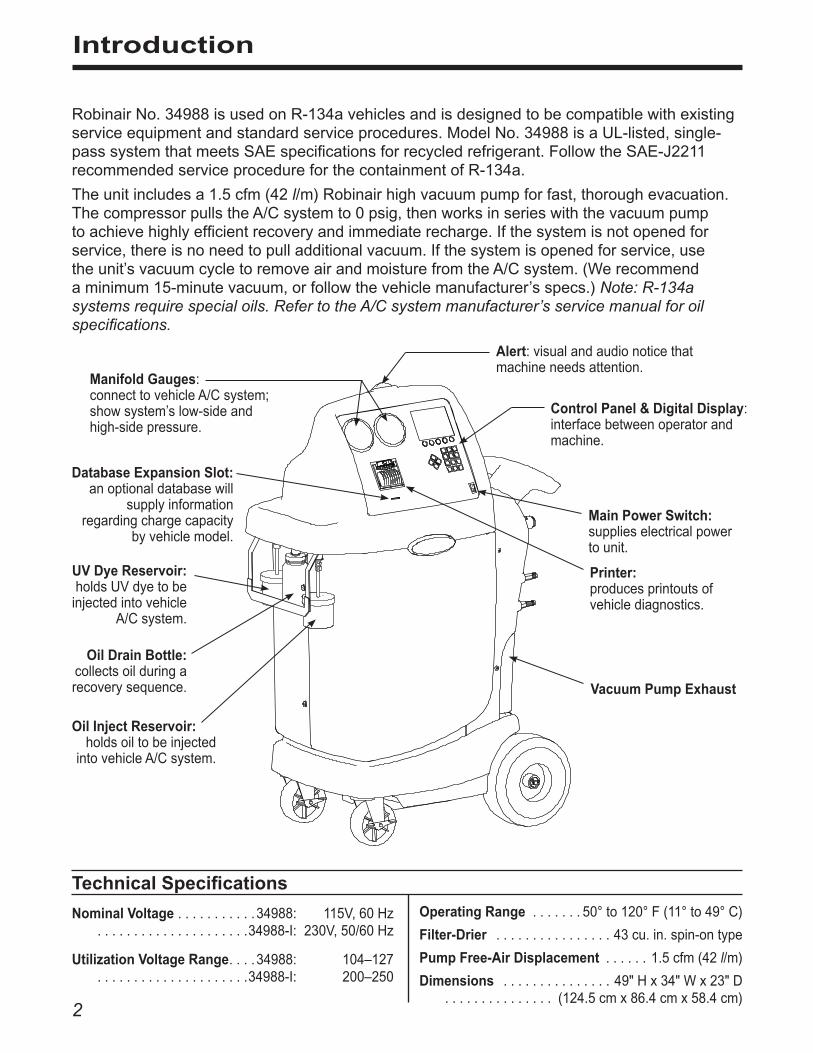
RobinairNo.34988isusedonR-134avehiclesandisdesignedtobecompatiblewithexistingserviceequipmentandstandardserviceprocedures.ModelNo.34988isaUL-listed,single-passsystemthatmeetsSAEspecificationsforrecycledrefrigerant.FollowtheSAE-J2211recommendedserviceprocedureforthecontainmentofR-134a.
Theunitincludesa1.5cfm(42l/m)Robinairhighvacuumpumpforfast,thoroughevacuation.ThecompressorpullstheA/Csystemto0psig,thenworksinserieswiththevacuumpumptoachievehighlyefficientrecoveryandimmediaterecharge.Ifthesystemisnotopenedforservice,thereisnoneedtopulladditionalvacuum.Ifthesystemisopenedforservice,usetheunit’svacuumcycletoremoveairandmoisturefromtheA/Csystem.(Werecommendaminimum15-minutevacuum,orfollowthevehiclemanufacturer’sspecs.)Note: R-134a systems require special oils. Refer to the A/C system manufacturer’s service manual for oil specifications.
Technical Specifications
Nominal Voltage . . . . . . . . . . .34988: 115V,60Hz. . . . . . . . . . . . . . . . . . . . .34988-I: 230V,50/60Hz
Utilization Voltage Range. . . .34988: 104–127. . . . . . . . . . . . . . . . . . . . .34988-I: 200–250
Operating Range . . . . . . . 50°to120°F(11°to49°C)
Filter-Drier . . . . . . . . . . . . . . . . 43cu.in.spin-ontype
Pump Free-Air Displacement . . . . . . 1.5cfm(42l/m)
Dimensions . . . . . . . . . . . . . . . 49"Hx34"Wx23"D . . . . . . . . . . . . . . . (124.5cmx86.4cmx58.4cm)
Control Panel & Digital Display: interfacebetweenoperatorandmachine.
Main Power Switch:supplieselectricalpowertounit.
Manifold Gauges:connecttovehicleA/Csystem;showsystem’slow-sideandhigh-sidepressure.
Printer: producesprintoutsofvehiclediagnostics.
Alert:visualandaudionoticethatmachineneedsattention.
Vacuum Pump Exhaust
UV Dye Reservoir:holdsUVdyetobeinjectedintovehicle
A/Csystem.
Oil Drain Bottle:collectsoilduringarecoverysequence.
Oil Inject Reservoir:holdsoiltobeinjected
intovehicleA/Csystem.
Database Expansion Slot: anoptionaldatabasewill
supplyinformation regardingchargecapacity
byvehiclemodel.

3554228 Rev. E July 30, 2013
Introduction
Control Panel Functions
AUTOMATIC activatesamenuthathelpstheusersetupanautomaticrecover/vacuum/leaktest/chargesequence.
CHARGE activatesthesequencethatchargesthevehicleA/Csystemwithaprogrammedamountofrefrigerant.
EXIT returnstestsequencetopreviousscreen.
HELP displaysscreensthatexplaininformationorstepstotake.
INJECT OIL injectsoilintovehicleA/Csystem.
NEXT displaysnextscreeninthesequence.
NO answersaquery.
PAUSE temporarilystopsthemachinefromrunningthecurrentsequence.
PRINT(whenitappearsonthecontrolpanel)producesaprintoutofscreencontent.Turningoffthemachineclearstheprintmemory.
RECOVER activatesthesequencetorecoverrefrigerantfromthevehiclesystem.
RESUME reactivatesapausedsequence.
SAVE storestheinformationloadedforfutureusebytheprogram.
START beginsafunction.
STOP terminatesafunction.
TOGGLE UNITS movesthecursorthroughchoicesonthescreen.
VACUUM activatesthesequencethatpullsadeepvacuumonthevehiclesystemtoremoveairandmoisture.
YESanswersaquery.
GlossaryA/C System :Thevehicleairconditioningsystembeingserviced.
Internal Storage Vessel (ISV):Therefillablerefrigerantstoragevesseldesignedspecificallyforthisunit;30lb.(14kg).
Source Tank :AdisposabletankofnewrefrigerantusedtorefilltheISV;notincluded.
Unit :ModelNo.34988.
Automatic Recover Vacuum Charge NextTimeDate
ARROWSareusedforscrollingthroughmenuitems.
CONTRASTdarker
CONTRAST lighter
ChoosecontrolpanelfunctionsbypressingtheSELECTkeythatappearsbelowthefunctiononthedisplay.

4
Introduction
Adjust Refill Default
When connected to a refrigerant source, the unitmaintainsapre-setamountofrefrigerantintheinternalstoragevessel.This valuemaybeadjustedupordowntosuittheuser’sneeds.(Thedefaultis15lbs.).
Refer to instructions outlined in the MaintenancesectionunderAdjust Tank Fill Level.
Calibration Check
Use to verify internal scale calibration. Refer toinstructions in Maintenance section under Scale Calibration Check.
Display ISV Info
Displays internal storage vessel (ISV) pressureandtemperature.UsetocheckISVforexcessivepressure.
Edit Print Header
Programinformationthatwillappearontheprintouteachtimetheprintfunctionisused.
Hose FlushFlushesresidualoilfromtheunittopreparefortheserviceofnextvehicle.
Maintain Filter
Thefilter-drierremovesacid,particulates,andmoisturefromtherefrigerant.TomeetSAEJ-2788requirements,itismandatorytoreplacethefilter-drierafter150lbs. (68kg)ofrefrigeranthasbeenfiltered.
Thismenu itemshowshowmuch refrigeranthasbeenfilteredsincethelastfilterchange,anddisplaysthefiltercapacityremaininguntilthemachinelocksdownandnolongerfunctions.
RefertotheinstructionsoutlinedintheMaintenancesectionunderReplace the Filter-Drier.
Maintain Vacuum Pump
Displayshowlongthevacuumpumphasoperatedsincethelastoilchange,andtheamountoftimeremaininguntilthenextoilchangeisneeded.Formaximum vacuum pump performance, changevacuumpumpoilafterevery10hoursofoperation.
RefertotheinstructionsoutlinedintheMaintenancesectionunderChange Vacuum Pump Oil.
Refrigerant Management
Displays the amount of refrigerant recovered,charged,andreplenished(forthelifeoftheunit),andfiltered(sincethelastfilterchange).
Relay X.XXX
Displaystherevisionleveloftherelayboardsoftwareintheunit.
Select Language
Choosetohavepromptsdisplayedinoneofthreelanguages:English,French,orSpanish.Englishisthedefaultlanguage.
Select Units
Programthemachinetodisplayunitsofmeasureinpounds,kilograms,ounces,orgrams.Thedefaultdisplayisinpounds.
Service Menu
ForRobinairservicecenteruseonly.
Set Date and Time
Usethekeypadtoprogramthemachineforthecurrentdateandtime.Press“2”forAMandpress“7”forPM.
System Flush
AmethodofremovingoilbyforcingliquidrefrigerantthroughanA/Csystemorcomponents.
Tank Fill
Transferrefrigerantfromthesourcetanktotheinternalstoragevessel(ISV).
Refer to instructions outlined in the MaintenancesectionunderManually Fill the ISV.
Version X.XXX
Displaystherevisionlevelofthesoftwareintheunit.
Menu Functions
5554228 Rev. E July 30, 2013
Setup
Figure 1
Important: To operate this equipment, the owner must complete and mail the MVAC Certification Form, and technicians must be certified with the Environmental Protection Agency (EPA).
Unpack the Accessory KitUnpacktheaccessorykitfromthebox,andremovetheplasticpackaging.Thekitconsistsof
• Acalibrationweight.• Vacuumpumpoil,oilfillercap,andtube.• Servicehoses.• Fourbottles—oilreservoir,oildrain,UVdyereservoir,sparereservoir.
• Threerollsofpaperfortheprinter.• Plasticpouchcontainingawarrantycard(tobe
completedandmailed),applicableMSDSsheets,aservicecenterlisting,andanenvelopeofMobileAirConditioningSociety(MACS)information.
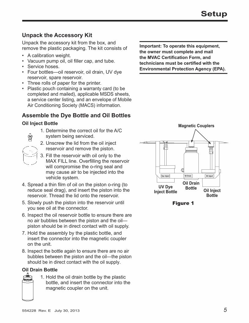
Assemble the Dye Bottle and Oil BottlesOil Inject Bottle
1.DeterminethecorrectoilfortheA/Csystembeingserviced.
2. Unscrewthelidfromtheoilinjectreservoirandremovethepiston.
3.FillthereservoirwithoilonlytotheMAXFILLline.Overfillingthereservoirwillcompromisetheo-ringsealandmaycauseairtobeinjectedintothevehiclesystem.
4.Spreadathinfilmofoilonthepistono-ring(toreducesealdrag),andinsertthepistonintothereservoir.Threadthelidontothereservoir.
5.Slowlypushthepistonintothereservoiruntilyouseeoilattheconnector.
6. Inspecttheoilreservoirbottletoensuretherearenoairbubblesbetweenthepistonandtheoil—pistonshouldbeindirectcontactwithoilsupply.
7.Holdtheassemblybytheplasticbottle,andinserttheconnectorintothemagneticcouplerontheunit.
8.Inspectthebottleagaintoensuretherearenoairbubblesbetweenthepistonandtheoil—thepistonshouldbeindirectcontactwiththeoilsupply.
Oil Drain Bottle
1.Holdtheoildrainbottlebytheplasticbottle,andinserttheconnectorintothemagneticcouplerontheunit.
Dye Inject Oil Drain Oil Inject
Oil Drain Bottle Oil Inject
Bottle
UV Dye Inject Bottle
Magnetic Couplers
6
Power Up the Unit1.Unwindthepowercordfromthehandle,andplugitintoacorrectvoltageoutlet.
2.Turnonthemainpowerswitch.Thefirsttimetheunitispoweredup,itdisplaystheinitialsetupmode.
Select LanguageTheoperatormaychoosetohavepromptsdisplayedinoneofthreelanguages:English,French,orSpanish.
1. UsetheUPorDOWNarrowkeytotogglethroughthechoices.RefertoFigure3.
2. SelectSAVEtochoosethedisplayedlanguage.
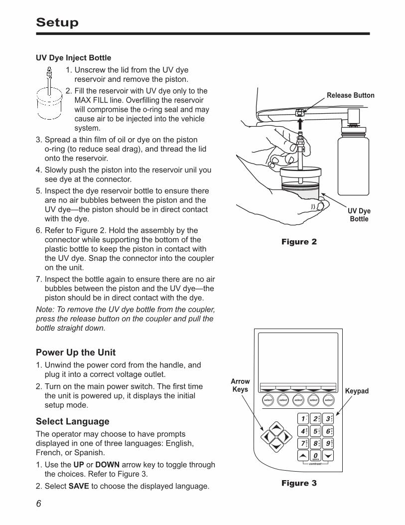
UV Dye Inject Bottle
1.UnscrewthelidfromtheUVdyereservoirandremovethepiston.
2. FillthereservoirwithUVdyeonlytotheMAXFILLline.Overfillingthereservoirwillcompromisetheo-ringsealandmaycauseairtobeinjectedintothevehiclesystem.
3.Spreadathinfilmofoilordyeonthepistono-ring(toreducesealdrag),andthreadthelidontothereservoir.
4. Slowlypushthepistonintothereservoirunilyouseedyeattheconnector.
5. InspectthedyereservoirbottletoensuretherearenoairbubblesbetweenthepistonandtheUVdye—thepistonshouldbeindirectcontactwiththedye.
6.RefertoFigure2.HoldtheassemblybytheconnectorwhilesupportingthebottomoftheplasticbottletokeepthepistonincontactwiththeUVdye.Snaptheconnectorintothecouplerontheunit.
7.InspectthebottleagaintoensuretherearenoairbubblesbetweenthepistonandtheUVdye—thepistonshouldbeindirectcontactwiththedye.
Note: To remove the UV dye bottle from the coupler, press the release button on the coupler and pull the bottle straight down.
Setup
Figure 2
UV Dye Bottle
Release Button
KeypadArrow Keys
Figure 3
7554228 Rev. E July 30, 2013
Select UnitsTheoperatormaychoosetohaveunitsofmeasuredisplayedinpounds,kilograms,ounces,orgrams.
1.UsetheUPorDOWNarrowkeyorselectTOGGLE UNITStotogglethroughthechoices.
2. SelectSAVE tochoosethedisplayedunitofmeasure.
Set Date and TimeThemachineisprogrammedatthefactoryforthelocaltimezoneanddate.Usethekeypadandarrowkeystorevisethatinformation.
1.Usethekeypadtoenterthedateandtime.Press“2”forAM;press“7”forPM.
2.SelectSAVE toacceptthedateandtime.
Adjust Tank Fill DefaultTheoperatormayeitheraccepttheunit’spre-setdefaultweightof15lbs.ofrefrigerantstoredintheinternalstoragevessel(ISV),orchangetheamounttoaccommodatetheapplication.Theunitdisplays
15.00LBS.ENTERTHEAMOUNTOFREFRIGERANTTHATTHETANKFILLFUNCTIONSHOULDMAINTAIN
INTHEINTERNALSTORAGEVESSEL. MAX=17.00LBMIN=04.00LB
SELECTSAVETOACCEPTOREXITTOABORT
1. SelectSAVEtoacceptthedefaultamount,orusethekeypadtoenteranamountandselectSAVE.
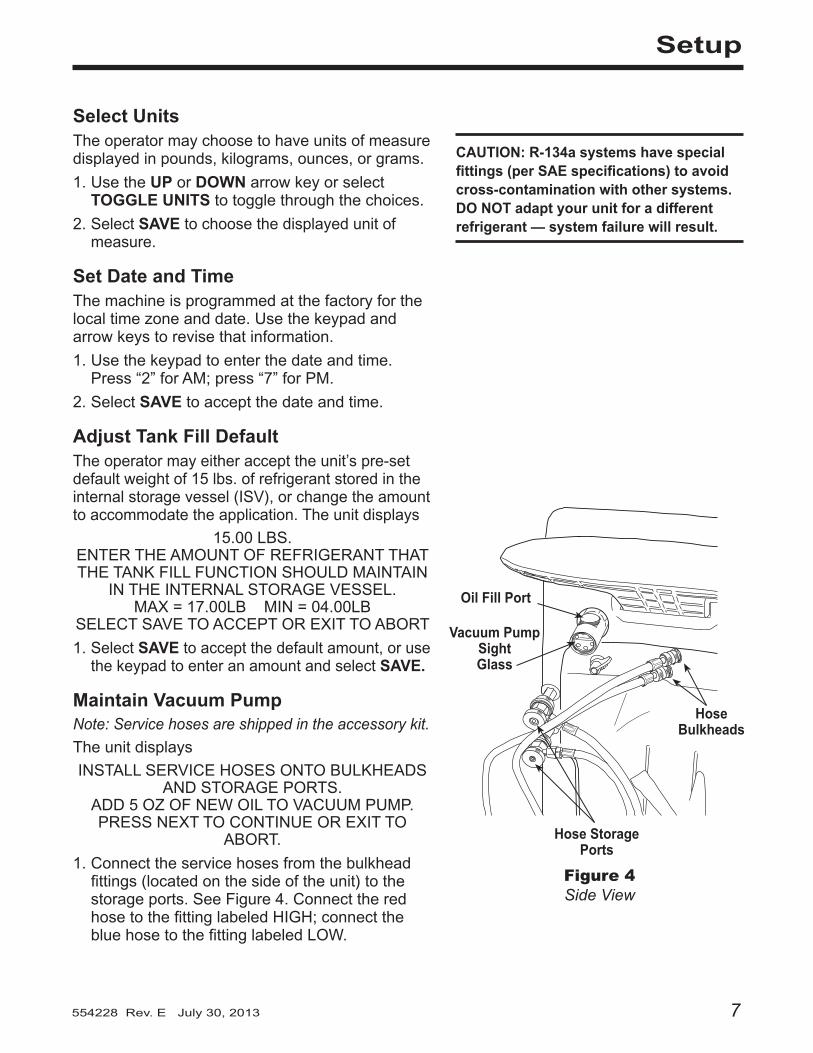
Maintain Vacuum PumpNote: Service hoses are shipped in the accessory kit.
Theunitdisplays
INSTALLSERVICEHOSESONTOBULKHEADSANDSTORAGEPORTS.
ADD5OZOFNEWOILTOVACUUMPUMP.PRESSNEXTTOCONTINUEOREXITTO
ABORT.
1.Connecttheservicehosesfromthebulkheadfittings(locatedonthesideoftheunit)tothestorageports.SeeFigure4.ConnecttheredhosetothefittinglabeledHIGH;connectthebluehosetothefittinglabeledLOW.
Figure 4Side View
Hose Bulkheads
Hose Storage Ports
Oil Fill Port
Vacuum Pump Sight Glass
Setup
CAUTION: R-134a systems have special fittings (per SAE specifications) to avoid cross-contamination with other systems . DO NOT adapt your unit for a different refrigerant — system failure will result .

8
Manual Tank Fill1.Afterthevacuumpumpshutsoff,theunitdisplays,
CONNECTSOURCETANKTO TANKFILLHOSE,OPENTANKVALVE,
ANDORIENTATETANK TOPROVIDELIQUIDSUPPLY.
PRESSSTARTTOBEGINOREXITTOABORT.
Connectthefillhosetotheliquidconnectoronafullsourcetank.SeeFigure5.
2.Openthesourcetankvalve.
3.Installthesourcetank,andsecureittotheunit(usingthetankstrap)insuchawaythatliquidrefrigerantissuppliedtotheconnection.
Figure 5Side View
Fill Hose(connecttoliquidline)
Source Tank Strap
CAUTION: The vacuum pump is shipped without oil in the reservoir . Failure to add oil will damage the vacuum pump .
2.Removetheplugfromthevacuumpumpoilfillport.
3. Attachtheflexibletube/captotheoilbottle(fromtheaccessorykit);pouronly five (5) ounces ofvacuumpumpoilintothefillport.Note: You will top off the oil in the next step as the vacuum pump is running.
4.SelectNEXT.Whilethevacuumpumpisrunning,slowlyaddoiluntilthelevelrisestothecenterofthesightglass.
5.Installthepluginthefillport,andselectEXIT. Theunitpullsa3-minutevacuumtoclearallinternalairbeforeproceeding.
Note: The “burping” noise heard during this process indicates air is being purged from the system—this is normal.
CAUTION: The unit is programmed to run the setup procedure as outlined here . To prevent personal injury, do NOT operate the unit at any other time without the oil fill port plug installed, because the vacuum pump is pressurized during normal operation .
Maintain Vacuum Pump contd .
Setup

9554228 Rev. E July 30, 2013
4.PressSTARTtobeginfillingtheinternalstoragevessel.Addatleast8lbs.ofrefrigeranttoensureenoughisavailableforcharging.
Thisprocesstakes15–20minutes.Theunitstopswhenthedesignatedamountofrefrigeranthasbeentransferredtotheinternaltank,orwhenthesourcetankisempty.
Note: Only the amount of refrigerant available for charging is displayed. For example, if the tank fill default is set at 15 lbs., the unit will transfer 15 lbs. to the ISV, but the display may show only 13 lbs.
5.Whenthefillprocessiscomplete,theunitisreadyforoperation.
Note: There is no need to calibrate the scale; it is calibrated at the factory.
Manual Tank Fill contd .
Setup
Edit Print HeaderThismachinehasthecapabilitytoprintoutrecovery,vacuum,charge,andflushinformationforeachvehicletested.
Theprintheaderinformationthatisenteredduringthisprocedurewillappearoneachprintout.Respondtothequestionsonthedisplayscreenbyusing
• thekeypadtoenterinformation,• theleftandrightarrowkeystomovethecursor,• thedownarrowtoclearinformation.
1.Enteryourdealershipnumber,andyourdealershipname,streetaddress,state,andzipcode.
2.Fourmorelinesareavailableforyoutospecifyotherinformationtoappearoneachprintout.
OnceatesthasbeencompletedandthePRINT keyhasbeenpressed,enterthevehicle'sVINandlicenseplatenumber.
Entering InformationThenumericalkeysonthekeypadincludeanalphabetthatisusedtoenterinformationintothemachine.Theprocedureissimilartotextmessaging.Forexample,
To enter an “A”:Pressthe2keyoncetoseethe“A”onthedigitaldisplay.
To enter a “2”:Pressthe2keyfourtimestoseethe“2” onthedigitaldisplay.Note: After the appropriate letter is shown on the display, pause for a moment until the cursor moves to the next position.
Operating Tips
10
Operating Instructions
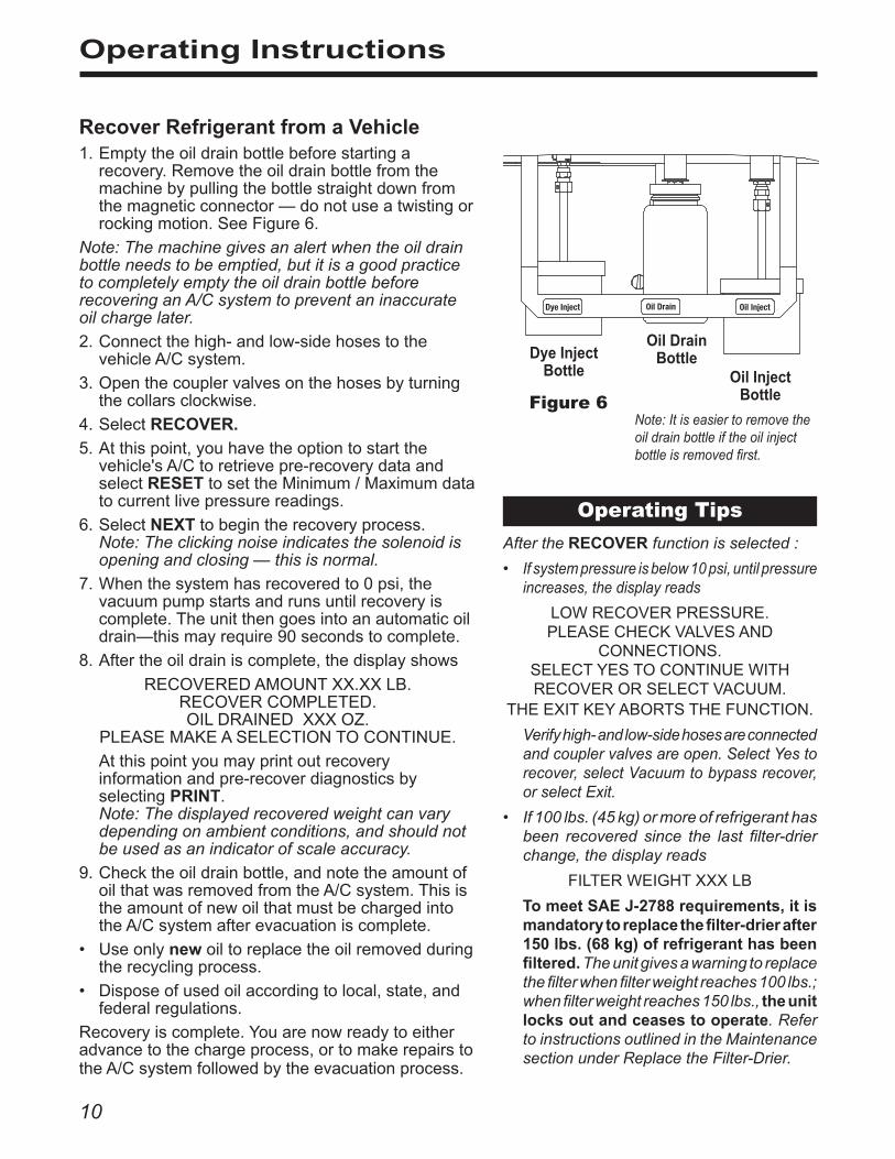
Recover Refrigerant from a Vehicle1.Emptytheoildrainbottlebeforestartinga
recovery.Removetheoildrainbottlefromthemachinebypullingthebottlestraightdownfromthemagneticconnector—donotuseatwistingorrockingmotion.SeeFigure6.
Note: The machine gives an alert when the oil drain bottle needs to be emptied, but it is a good practice to completely empty the oil drain bottle before recovering an A/C system to prevent an inaccurate oil charge later.
2.Connectthehigh-andlow-sidehosestothevehicleA/Csystem.
3.Openthecouplervalvesonthehosesbyturningthecollarsclockwise.
4.SelectRECOVER.
5.Atthispoint,youhavetheoptiontostartthevehicle'sA/Ctoretrievepre-recoverydataandselectRESETtosettheMinimum/Maximumdatatocurrentlivepressurereadings.
6.SelectNEXTtobegintherecoveryprocess.Note: The clicking noise indicates the solenoid is opening and closing — this is normal.
7.Whenthesystemhasrecoveredto0psi,thevacuumpumpstartsandrunsuntilrecoveryiscomplete.Theunitthengoesintoanautomaticoildrain—thismayrequire90secondstocomplete.
8.Aftertheoildrainiscomplete,thedisplayshows
RECOVEREDAMOUNTXX.XXLB.RECOVERCOMPLETED.OILDRAINEDXXXOZ.
PLEASEMAKEASELECTIONTOCONTINUE.
Atthispointyoumayprintoutrecoveryinformationandpre-recoverdiagnosticsbyselectingPRINT. Note: The displayed recovered weight can vary depending on ambient conditions, and should not be used as an indicator of scale accuracy.
9.Checktheoildrainbottle,andnotetheamountofoilthatwasremovedfromtheA/Csystem.ThisistheamountofnewoilthatmustbechargedintotheA/Csystemafterevacuationiscomplete.
• Useonlynewoiltoreplacetheoilremovedduringtherecyclingprocess.
• Disposeofusedoilaccordingtolocal,state,andfederalregulations.
Recoveryiscomplete.Youarenowreadytoeitheradvancetothechargeprocess,ortomakerepairstotheA/Csystemfollowedbytheevacuationprocess.
Figure 6
Oil Drain Bottle
Oil Inject Bottle
Dye Inject Bottle
Note: It is easier to remove the oil drain bottle if the oil inject bottle is removed first.
Dye Inject Oil Drain Oil Inject
Operating TipsAfter the RECOVER function is selected :
• If system pressure is below 10 psi, until pressure increases, the display reads
LOWRECOVERPRESSURE. PLEASECHECKVALVESAND
CONNECTIONS. SELECTYESTOCONTINUEWITHRECOVERORSELECTVACUUM.
THEEXITKEYABORTSTHEFUNCTION.
Verify high- and low-side hoses are connected and coupler valves are open. Select Yes to recover, select Vacuum to bypass recover, or select Exit.
• If 100 lbs. (45 kg) or more of refrigerant has been recovered since the last filter-drier change, the display reads
FILTERWEIGHTXXXLB
To meet SAE J-2788 requirements, it is mandatory to replace the filter-drier after 150 lbs. (68 kg) of refrigerant has been filtered. The unit gives a warning to replace the filter when filter weight reaches 100 lbs.; when filter weight reaches 150 lbs., the unit locks out and ceases to operate. Refer to instructions outlined in the Maintenance section under Replace the Filter-Drier.
11554228 Rev. E July 30, 2013
Evacuate the A/C System1.EnsureservicehosesareconnectedtothevehicleA/Csystem,andcouplervalvesareOPEN.
2.SelectVACUUM.
3.Theunitgivesyoutheoptionofdoingaleaktestafterevacuation.SelectTOGGLE LEAK toturntheleaktestOFF/ON.
4. SelectSTART toacceptthedefaultevacuationtime,orenterthedesiredvacuumtimeusingthenumberkeys,andselectSTART.
IMPORTANT: The unit pulls a vacuum on the vehicle A/C system to remove air and boil off moisture that may be present in the system . Evacuate the system for at least 10 minutes, or follow the A/C system manufacturer’s specifications, to ensure adequate moisture and contaminant removal .
5.TheunitevacuatestheA/Csystemandstopswhenthespecifiedamountoftimehaselapsed.SelectEXITtocontinue.
Note: During the vacuum process, the unit may perform a tank fill or an air purge, if needed.
YouarenowreadytoeithermanuallyreplenishtheA/Csystemwithnewoilortorechargethesystemwithrefrigerant.
Operating Tips• If the vacuum pump has run for 10 or
more hours without an oil change, the unit displays
MAINTAINVACUUMPUMPVACUUMOILTIMEXX:XXOILLIFEREMAININGXX:XX
CHANGEVACUUMPUMPOILNOW?SELECTYESTOCHANGEOIL
ORNOTOEXIT.
Refer to instructions in the Maintenance section under Change Vacuum Pump Oil.
• Before the unit begins evacuating the A/C system, it checks for any pressure in the system that might damage the vacuum pump. If pressure is detected, the unit displays
PRESSURETOOHIGHFORVACUUM!PRESSEXIT
Select EXIT, and recover refrigerant before proceeding.
• If a leak test was programmed and a leak is detected, the unit displays
LEAKTESTFAILEDPRESSYESTOCONTINUE
NOTOABORT
Select NO to exit the evacuation, perform needed repairs, and repeat the evacuation.
• To ensure an accurate leak test, it is imperative that a thorough recovery and evacuation of the system be performed. During the recovery process, cold spots can develop in the A/C system. Pockets of refrigerant in desiccant and in system oil will continue to vaporize as the A/C system temperature equalizes toward ambient. As this occurs, A/C system pressure will increase, which may be interpreted by the unit as a leak.
This will vary somewhat with ambient temperature conditions.
Operating Instructions
12
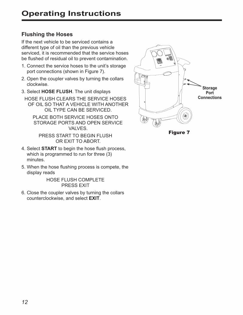
Flushing the HosesIfthenextvehicletobeservicedcontainsadifferenttypeofoilthanthepreviousvehicleserviced,itisrecommendedthattheservicehosesbeflushedofresidualoiltopreventcontamination.
1.Connecttheservicehosestotheunit’sstorageportconnections(showninFigure7).
2.Openthecouplervalvesbyturningthecollarsclockwise.
3.SelectHOSE FLUSH.Theunitdisplays
HOSEFLUSHCLEARSTHESERVICEHOSESOFOILSOTHATAVEHICLEWITHANOTHER
OILTYPECANBESERVICED.
PLACEBOTHSERVICEHOSESONTOSTORAGEPORTSANDOPENSERVICE
VALVES.
PRESSSTARTTOBEGINFLUSH OREXITTOABORT.
4.SelectSTART tobeginthehoseflushprocess,whichisprogrammedtorunforthree(3)minutes.
5.Whenthehoseflushingprocessiscompete,thedisplayreads
HOSEFLUSHCOMPLETEPRESSEXIT
6.Closethecouplervalvesbyturningthecollarscounterclockwise,andselectEXIT.
Figure 7
Storage Port
Connections
Operating Instructions
13554228 Rev. E July 30, 2013
Operating Instructions
Recharge the A/C System1.Connectservicehosestothevehicle’sserviceports.
2.SelectCHARGE.Thedisplayreads
CHARGEMENUCHARGEAMOUNT:0.00LBCHARGEMODE:______SIDE
USEARROWKEYSTOSCROLLUNITS.
3.Atthispoint,selectINJECT OIL,ifnecessary.Thedisplayreads
OILXXXINJECTDYE_______
Usethenumberkeystoentertheamountofoiltoinject.
4.SelectTOGGLE DYEtoturndyeinjectONorOFF.SelectSAVEtoreturntothechargescreen.
5. SelectMODEtotogglebetweenahigh-sideorlow-sidecharge,orboth.Note: Charge mode after injecting oil allows only a high-side charge.
6.Typeinachargeweightusingthenumberkeys.SelectSTART.
Movingorbumpingtheunitatthispointmayresultinaninaccuratecharge.
Note:
• During a charge cycle, if the unit fails to transfer refrigerant due to low tank pressure, the charge process is automatically interrupted and the unit operates in a mode to build tank pressure. Once tank pressure is sufficient, the unit automatically completes the charge.
• When the charge cycle gets close to the weight entered in Step 6, the unit slows down. It will charge, settle, charge again, settle, etc.
• Before it charges, the unit may purge air out of the ISV to minimize the amount of noncondensable gases that could contaminate the A/C system.
Operating Tips• After selecting the CHARGE function and
entering a desired weight, if the weight entered will leave less than 2 lbs. (.91 kg) of refrigerant in the internal tank after charge, the charge function will not start. The display reads
INSUFFICIENTREFRIG.THEREISNOTENOUGHREFRIGERANTIN
THEISVTOCOMPLETECHARGE. PRESSTANKFILLTOADDMORE
OREXITTOABORT.
Refer to the Maintenance section for instructions to Manually Fill the Internal Storage Vessel (ISV).
• After selecting INJECT OIL, if the oil inject bottle is not in the correct position, the display reads
INJECTOILBOTTLEWEIGHTISLOWCHECKOILBOTTLE
RETRYOREXITTOABORT
Verify the oil inject bottle is attached to the machine as explained in the Setup section.
• After selecting INJECT OIL, if there is an insufficient amount of new oil in the oil inject bottle, the display reads
INJECTOILHASSTALLEDCHECKOILBOTTLE
RETRYOREXITTOABORT
Fill the oil inject bottle with new oil as explained in the Setup section.
• If pressure is detected, the unit displays
PRESSURETOOHIGHFORINJECT!PRESSEXIT
Select EXIT, and recover refrigerant before proceeding.

14
Operating Instructions
Recharge the A/C System contd .
7.Whenthechargeiscomplete,thedisplayshows
CHARGEDIAGNOSTICS
HIGHSIDEXXPSIMAXXXPSILOWSIDEXXPSIMINXXPSI
CHARGEAMOUNT:XX.XXLBS
STARTA/CTOPERFORMDIAGNOSTICSORWITHA/COFF,PRESSNEXTTOCLEAR
HOSES.
Toobtaincurrentpressurereadingsanddiagnosticsfromthevehicle,startthevehicle'sairconditioningsystem(setatmaximumoutput),orselectNEXTtocontinue.
8.Theunitdisplays
CHARGECOMPLETE
SELECTEQUALIZETOUSEA/CSYSTEM TOCLEARHOSES.
SELECTCOMPENSATETOUSEHOSECOMPENSATIONANDNOTRUNA/CSYSTEM.
SelectEQUALIZEtoensureallliquidrefrigeranttrappedinthehosesistransferredtothevehicleA/Csystemforanaccuratecharge.
OR
SelectCOMPENSATEtochargeasmallamountofrefrigerantintothevehicleA/Csystemtooffsetanyrefrigerantthatmaybeleftinthehoses.
WARNING: To prevent personal injury,
• Verify the vehicle is in park or neutral with the emergency brake ON before starting the engine .
• Never run a vehicle without adequate ventilation in the work area .

15554228 Rev. E July 30, 2013
9. IfCOMPENSATEwasselected,thedisplayreads
HOSECOMPENSATIONINPROGRESSPLEASEWAIT
DONOTDISTURBUNITORCHARGEACCURACYWILLBEAFFECTED.
HOSECLEARDISCONNECTLOWSIDEAND
HIGHSIDEHOSESFROMA/CSYSTEM.
SELECTNEXTTOCONTINUE OREXITTOABORT.
10. Closecouplervalves.RemoveservicehosesfromtheA/Csystemandinstallonunit'sstorageports.
CAUTION: If the low-side or high-side coupler valves are left open during the hose clearing process, the system will pull refrigerant back out of the vehicle .
11. SelectNEXT tobeginclearinghosestopreparethemachineforthenextservice.
Whenthehosesareclear,thedisplayreads
REFRIGERANT:XX.XXLBSOURCETANKEMPTY
SELECTFUNCTIONUSINGKEYSBELOW
TheA/Csystemisnowreadyforuse.
Operating Instructions
Recharge the A/C System contd .
9. IfEQUALIZEwasselected,thedisplayreads
HOSEEQUALIZECONNECTLOWSIDESERVICEHOSETOA/CSYSTEMANDOPENCOUPLER.
MAKESUREHIGHSIDEHOSEISDISCONNECTEDFROMA/CSYSTEM.STARTA/CSYSTEMONMAXAND/OR
RECIRCULATE. Closethehigh-sidecouplervalve.The
high-sidehosemayberemovedfromthevehicle,butthe low-side hose must stay connected to the vehiclewiththelow-sidecoupleropen.
10. Placethevehiclegearselectorinparkorneutral,withtheemergencybrakeON.
11. Startthevehicle.SettheA/Csystematmaximumoutput.
12.SelectNEXT.ThedisplayreadsEQUALIZINGHOSES.PLEASEWAIT.
Theunitinternallyconnectsthelow-andhigh-sidehoses,allowingthevehicle’scompressortopullrefrigerantintothe A/Csystem.
13. Whenthechargeiscomplete,theunitdisplays
DISCONNECTLOWSIDEANDHIGHSIDEHOSESFROMA/CSYSTEM
Closethelow-sidecouplervalve.RemoveservicehosesfromA/Csystemandinstallonunit'sstorageports.ShutOFFvehicle.
CAUTION: If the low-side or high-side coupler valves are left open during the hose clearing process, the system will pull refrigerant back out of the vehicle .
14. SelectNEXT tobeginclearinghosestopreparethemachineforthenextservice.
Whenthehosesareclear,thedisplayreturnstothemainmenu,andtheA/Csystemisnowreadyforuse.
16
Operating Instructions – Automatic
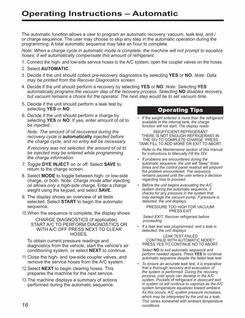
Theautomaticfunctionallowsausertoprogramanautomaticrecovery,vacuum,leaktest,and/orchargesequence.Theusermaychoosetoskipanystepintheautomaticoperationduringtheprogramming.Atotalautomaticsequencemaytakeanhourtocomplete.
Note: When a charge cycle in automatic mode is complete, the machine will not prompt to equalize hoses; it will automatically compensate this amount of refrigerant.
1. Connectthehigh-andlow-sideservicehosestotheA/Csystem;openthecouplervalvesonthehoses.
2.SelectAUTOMATIC.
3.Decideiftheunitshouldcollectpre-recoverydiagnosticsbyselectingYESorNO. Note: Data may be printed from the Recover Diagnostics screen.
4. DecideiftheunitshouldperformarecoverybyselectingYESorNO. Note: Selecting YES automatically programs the vacuum step of the recovery process. Selecting NO disables recovery, but vacuum remains a choice for the operator. The next step would be to set vacuum time.
Operating Tips• If the weight entered is more than the refrigerant
available in the internal tank, the charge function will not start. The display reads
INSUFFICIENTREFRIGERANTTHEREISNOTENOUGHREFRIGERANTINTHEISVTOCOMPLETECHARGE.PRESS
TANKFILLTOADDMOREOREXITTOABORT.
Refer to the Maintenance section of this manual for instructions to Manually Fill the ISV.
• If problems are encountered during the automatic sequence, the unit will “beep” three times and the control panel readout will pinpoint the problem encountered. The sequence remains paused until the user enters a decision regarding how to proceed.
• Before the unit begins evacuating the A/C system during the automatic sequence, it checks for any pressure in the system that may damage the vacuum pump. If pressure is detected, the unit displays
PRESSURETOOHIGHFORVACUUM!PRESSEXIT
Select EXIT. Recover refrigerant before proceeding.
• If a leak test was programmed, and a leak is detected, the unit displays
LEAKTESTFAILEDCONTINUEWITHAUTOMATICMODE?
PRESSYESTOCONTINUENOTOABORT.
Select NO to exit automatic sequence and perform needed repairs. Press YES to continue automatic sequence despite the failed leak test.
• To ensure an accurate leak test, it is imperative that a thorough recovery and evacuation of the system is performed. During the recovery process, cold spots can develop in the A/C system. Pockets of refrigerant in desiccant and in system oil will continue to vaporize as the A/C system temperature equalizes toward ambient. As this occurs, A/C system pressure increases, which may be interpreted by the unit as a leak. This varies somewhat with ambient temperature conditions.
5.DecideiftheunitshouldperformaleaktestbyselectingYESorNO.
6.DecideiftheunitshouldperformachargebyselectingYESorNO.Ifyes,enteramountofoiltobeinjected.
Note: The amount of oil recovered during the recovery cycle is automatically injected before the charge cycle, and no entry will be necessary.
If recovery was not selected, the amount of oil to be injected may be entered while programming the charge information.
7. ToggleDYE INJECTonoroff.SelectSAVEtoreturntothechargescreen.
8.SelectMODEtotogglebetweenhigh-orlow-sidecharge,orboth.Note: Charge mode after injecting oil allows only a high-side charge. Enterachargeweightusingthekeypad,andselectSAVE.
9.Thedisplayshowsanoverviewofalltestsselected.SelectSTART tobegintheautomaticsequence.
10.Whenthesequenceiscomplete,thedisplayshows
CHARGEDIAGNOSTICS(ifapplicable)STARTA/CTOPERFORMDIAGNOSTICSOR
WITHA/COFFPRESSNEXTTOCLEARHOSES.
Toobtaincurrentpressurereadingsanddiagnosticsfromthevehicle,startthevehicle'sairconditioningsystem,orselectNEXTtocontinue.
11.Closethehigh-andlow-sidecouplervalves,andremovetheservicehosesfromtheA/Csystem.
12. SelectNEXT tobeginclearinghoses.Thispreparesthemachineforthenextservice.
13. Themachinedisplaysasummaryofactionsperformedduringtheautomaticsequence.

17554228 Rev. E July 30, 2013
System Flush
System Flushing ProcessThisunitprovidesamethodofremovingoilbyforcingliquidrefrigerantthroughanA/Csystem,orcomponentsofanA/Csystem.Aspecialflushingadapter(purchasedseparately)accessestheA/Csystematthecompressorblock.Afterflushing,therefrigerantisrecoveredbytheunitandfilteredbytherecyclingcircuit,returningittoSAEpuritylevels.
A/Csystemsvaryandmayrequiretheadaptingandflushingofindividualcomponents.Thefollowingprocedureworkswithanorificetubesystem.Refertoanyservicebulletinsasneededduringthisprocedure.
Notes:
• The unit must have at least 10 lbs. of refrigerant available in the ISV (as indicated on the display) for charging.
• If the flush process is interrupted by an accidental power-down or other fault, use the Recover mode to remove the refrigerant from the vehicle.
Setup
1.Verifytheoildrainbottleonthesideoftheunitisempty.SeeFigure8.RecoverrefrigerantasoutlinedinthismanualunderRecover Refrigerant from a Vehicle.
2.Closeservicecouplervalvesanddisconnecthosesfromvehicleaccessports.
3.Closethevalveontheexternalsourcetank.
Note: During this procedure, up to 12 lbs. of refrigerant is charged into the vehicle A/C system. If the flushing cycle is stopped before it is complete and the external source valve is open, the unit automatically adds refrigerant to the ISV, and there will be no room to recover the refrigerant used for flushing.
4.RemovetheA/Csystemorificetube,andreconnectthefittingstocreateabypass.
5.Disconnectthecompressorblockattherearofthecompressor.
Oil Drain Bottle
Figure 8
18
System Flush
6. Attachthecompressorblockadapter(fromtheflushingkit)tothesystemsideofthecompressorblock.
7.Configuretheblockconnectorstoprovideforward-orback-flushingoftherefrigerant.Note: Refrigerant flows from the red high-side connector to the blue low-side connector.
8.Opentheredservicecoupler.
9.Connectthefilterhousingtothedesiredreturnsideoftheadapterblockandtothebluelow-sidehose.
10. Opentheblueservicecoupler.
11.Verifythataflushingfilteriscorrectlyinstalledintheflushingfilterhousing.Opentheisolationvalveonthehose.
Operating Instructions
1.SelectSYSTEM FLUSH.
2.SelectSTART toacceptthedefaultflushtimeof10minutes,orenterthedesiredflushtimeusingthekeypadandselectSTART .
3.ThevacuumpumprunsforfiveminutestoremoveairfromtheA/Csystem,ifneeded.
4. Theunitflushesthesystemforthedesignatedlengthoftime,andthenentersarecoverymode.
5. Oilthathasbeencollecteddrainsintothegraduatedoildrainbottle.Removethebottleandmeasuretheoil.
Disposeofoilaccordingtothelawsinyourjurisdiction.Itistheresponsibilityoftheusertodetermineifamaterialisahazardouswasteatthetimeofdisposal.
6. WhentheunitdisplaysFLUSHCOMPLETE,closeservicecouplers,removehoses,andreassemblethevehicle’sA/Csystemtoitsoriginalstate.
7.Openthevalveonthesourcetank.
8.Evacuateandrechargethevehicleaccordingtotheinstructionsinthismanual.
WARNING: Do NOT disconnect service couplers during the flushing process . Refrigerant could spray out of the fittings, and exposure may cause personal injury .
Operating TipsIf the external flushing filter is plugged, the unit displays
NOFLOWDETECTED.FLUSHFILTERMAYBEBLOCKED.
CHECKCONNECTIONSANDVALVEPOSITIONS.
TOCLEARFILTERFORREPLACEMENT,CLOSEFLUSHFILTERADAPTERVALVEAND
SELECTSTART.SELECTEXITTOABORT
ORRETRYTOCONTINUEWITHOUTREPLACINGFILTER.
The message repeats until the filter is replaced.
19554228 Rev. E July 30, 2013
Maintenance
General Maintenance1.Onaregularbasis,wipeofftheunitusingacleanclothtoremovegreaseanddirt.
2. Periodicallycheckinternalcomponentsforleaks;overtime,fittingscanloosenastheunitismoved.Openthedoorpanel,andtracelinesusingaleakdetector.Checkconnectionsonthebackoftheunit.Tightenanyloosefittingsorconnectionsyoumayfind.
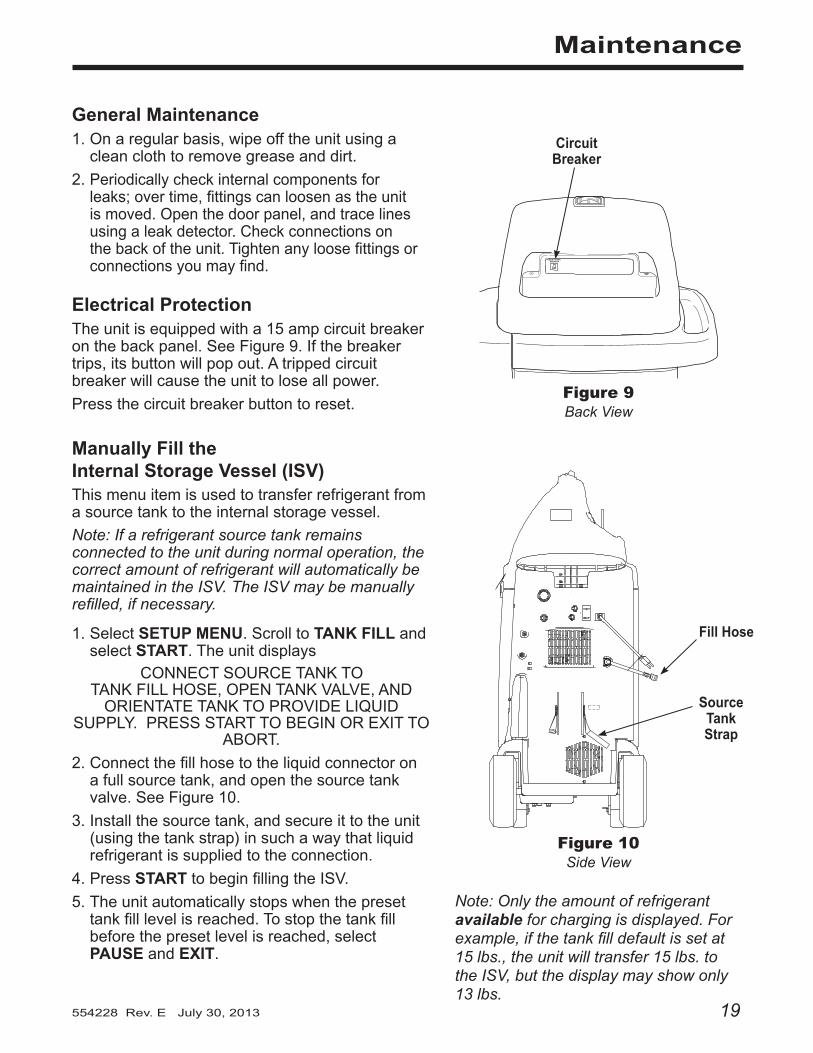
Electrical ProtectionTheunitisequippedwitha15ampcircuitbreakeronthebackpanel.SeeFigure9.Ifthebreakertrips,itsbuttonwillpopout.Atrippedcircuitbreakerwillcausetheunittoloseallpower.
Pressthecircuitbreakerbuttontoreset.
Manually Fill the Internal Storage Vessel (ISV)Thismenuitemisusedtotransferrefrigerantfromasourcetanktotheinternalstoragevessel.
Note: If a refrigerant source tank remains connected to the unit during normal operation, the correct amount of refrigerant will automatically be maintained in the ISV. The ISV may be manually refilled, if necessary.
1.SelectSETUP MENU.ScrolltoTANK FILLandselectSTART.Theunitdisplays
CONNECTSOURCETANKTO TANKFILLHOSE,OPENTANKVALVE,ANDORIENTATETANKTOPROVIDELIQUID
SUPPLY.PRESSSTARTTOBEGINOREXITTOABORT.
2.Connectthefillhosetotheliquidconnectoronafullsourcetank,andopenthesourcetankvalve.SeeFigure10.
3.Installthesourcetank,andsecureittotheunit(usingthetankstrap)insuchawaythatliquidrefrigerantissuppliedtotheconnection.
4.PressSTART tobeginfillingtheISV.
5.Theunitautomaticallystopswhenthepresettankfilllevelisreached.Tostopthetankfillbeforethepresetlevelisreached,selectPAUSEandEXIT.
Figure 10Side View
Fill Hose
Source Tank Strap
Circuit Breaker
Figure 9Back View
MAIN POWERBREAKER
Note: Only the amount of refrigerant available for charging is displayed. For example, if the tank fill default is set at 15 lbs., the unit will transfer 15 lbs. to the ISV, but the display may show only 13 lbs.

20
Figure 11
Tank Fill Hose Filter ServiceTheblacktankfillhoseattherearofthemachinecontainsafilterthatcanbecleanedwhenitappearsthatrefrigerantflowisrestricted.
Whenthemachinesenseslowflow,itmaydisplaythefollowingmessage:
• SOURCETANKEMPTY,butyetyouknowthesourcetankcontainsrefrigerant,connectionsaresecure,andthesourcetankvalveisopen.
Thecausemaybethatthetankfillhosefilterisplugged.
Cleaning the Tank Fill Hose Filter
1. Firstensurethatpressuredoesnotexistinthe line.Disconnecttheexternalsourcetank,andperformamanualtankfilltocaptureanyrefrigerantintheline.
2. Slowlyandcarefullydisconnectthetankfillhosefromtheadapter.Theremaystillbealittlepressureintheline.
3. DisassemblethetankfillhoseatthefilterhousingasshowninFigure11.
4. Removeandcleanthefilter.
5. Afterthefilterhasbeeninstalledbackintothefilterhousing,torquethehousingassemblyto8.5N•m(6ft.lbs.).
Maintenance
Disassemble the filter housing.

21554228 Rev. E July 30, 2013
Replace the Filter-DrierThefilter-drierisdesignedtotrapacidandparticulates,andtoremovewaterfromrefrigerant.TomeettheSAEJ-2788mandateforadequatemoistureandcontaminantremoval,thefilter-driermustbereplacedafter150lbs.(68kg)ofrefrigeranthasbeenfiltered.
Therefore, you no longer have a choice—the filter-drier must be replaced.Theunitgivesawarningwhen100lbs.ofthefiltercapacityhasbeenused;the unit locks down when the 150 lb. filter capacity has been reached and will no longer function.Forthisreason,alwayshaveaspareRobinairNo.34724filter-drieronhand.
Check Remaining Filter Capacity
1.SelectSETUP MENU.ScrolltoMAINTAIN FILTERandselectSTART.Theunitdisplays
FILTERCAPACITYUSED:XXXLBSFILTERCAPACITYREMAINING:XXXLBS
CHANGEFILTERNOW?SELECTYESTOCHANGEFILTEROR
NOTOCONTINUE.
Theunitdisplaystheamountofrefrigerantrecoveredsincethelastfilterchange,andtheamountoffiltercapacityremaininguntilthemachinelocksdown.
2.SelectYEStochangethefilter;NO toresumeusingthemachine.
Change the Filter
1.IfYES wasselectedattheendoftheCheck Remaining Filter Capacityprocedure,theunitdisplays
____________________ENTERNEWFILTERSERIALNUMBER
SELECTSAVETOCONTINUEOREXITTOABORT.
2. Usethekeypadtoentertheserialnumberthatappearsonthenewfilter-drier,andselectSAVE.
Note: If SERIALNUMBERUSEDORINVALIDis displayed, the serial number has been incorrectly entered or the filter-drier has already been used in this unit.
3. Ifthereispressureinthefilter,theunitperformsaclearingprocessanddisplaysCLEARINGFILTER.
IMPORTANT: Use only authentic Robinair No. 34724 filter-driers in this machine . All performance tests and claims are based on using this specific filter-drier.
Only the Robinair No. 34724 filter-drier includes the code necessary to make the unit operable again .
Enter the Serial No. for a New Filter-DrierThenumericalkeysonthekeypadincludeanalphabetthatisusedtoentertheserialnumbercodeforthenewfilter-drier.Theprocedureissimilartotextmessaging.Forexample,
To enter an “A”:Pressthe2 key oncetoseethe“A”onthedigitaldisplay.
To enter a “2”:Pressthe2 key fourtimestoseethe“2”onthedigitaldisplay.
Aftertheappropriateletterisshownonthedisplay,pauseforamomentuntilthecursormovestothenextposition.
Operating Tips
Maintenance
22
Maintenance
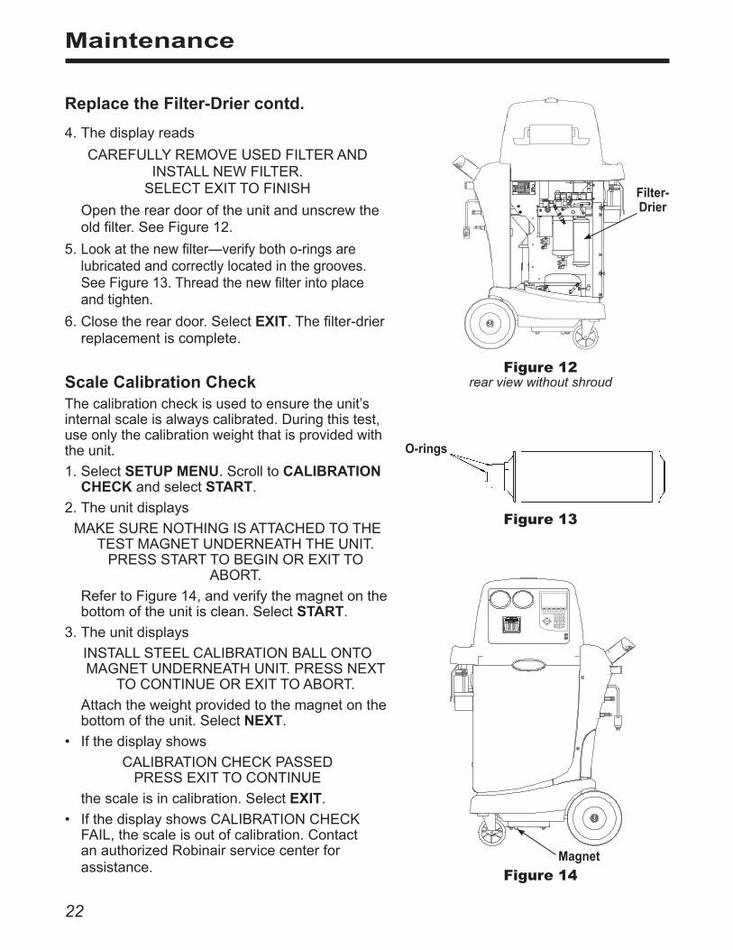
4.Thedisplayreads
CAREFULLYREMOVEUSEDFILTERANDINSTALLNEWFILTER.SELECTEXITTOFINISH
Openthereardooroftheunitandunscrewtheoldfilter.SeeFigure12.
5. Lookatthenewfilter—verifybotho-ringsarelubricatedandcorrectlylocatedinthegrooves.SeeFigure13.Threadthenewfilterintoplaceandtighten.
6.Closethereardoor.SelectEXIT.Thefilter-drierreplacementiscomplete.
Replace the Filter-Drier contd .
Filter-Drier
Figure 12rear view without shroudScale Calibration Check
Thecalibrationcheckisusedtoensuretheunit’sinternalscaleisalwayscalibrated.Duringthistest,useonlythecalibrationweightthatisprovidedwiththeunit.
1.SelectSETUP MENU.ScrolltoCALIBRATION CHECKandselectSTART.
2.Theunitdisplays
MAKESURENOTHINGISATTACHEDTOTHETESTMAGNETUNDERNEATHTHEUNIT.PRESSSTARTTOBEGINOREXITTO
ABORT.
RefertoFigure14,andverifythemagnetonthebottomoftheunitisclean.SelectSTART.
3.Theunitdisplays
INSTALLSTEELCALIBRATIONBALLONTOMAGNETUNDERNEATHUNIT.PRESSNEXT
TOCONTINUEOREXITTOABORT.
Attachtheweightprovidedtothemagnetonthebottomoftheunit.SelectNEXT.
• Ifthedisplayshows
CALIBRATIONCHECKPASSEDPRESSEXITTOCONTINUE
thescaleisincalibration.SelectEXIT.
• IfthedisplayshowsCALIBRATIONCHECKFAIL,thescaleisoutofcalibration.ContactanauthorizedRobinairservicecenterforassistance.
Magnet
Figure 14
O-rings
Figure 13

23554228 Rev. E July 30, 2013
Maintenance
Change Vacuum Pump OilFormaximumvacuumpumpperformance,changethevacuumpumpoilafterevery10hoursofoperation.
1.SelectSETUP MENU.ScrolltoMAINTAIN VACUUM PUMPandselectSTART.
Thedisplayshowshowlongthevacuumpumphasoperatedsincethelastoilchangeandtheamountoftimeremaininguntilthenextoilchangeisneeded:
VACUUMOILTIME:XX:XXOILLIFEREMAINING:XX:XX
CHANGEVACUUMPUMPOILNOW?SELECTYESTOCHANGEOILORNOTOEXIT
2.SelectYES.Thedisplayshows
WARMINGOILFORBETTERDRAIN.VACUUMTIME:XX:XX
Allowthevacuumpumptorununtilitautomaticallystops.Thiswilltakeapproximatelyoneminute.
3.Thedisplaythenshows
DRAINUSEDOILANDADD5OZOFNEWOIL.PRESSNEXTTOCONTINUEOREXITTOABORT.
RefertoFigure15,andremovetheplugfromtheoilfillport.(Thepumpdrainsfasterwhenvented.)
4. Removetheoildrainfittingcap,anddraintheoilintoasuitablecontainerfordisposal.Replacethecap.
5. Attachtheflexibletube/captotheoilbottle(fromtheaccessorykit).Pouronly five (5) ounces ofvacuumpumpoilintothefillport.Note: You will top off the oil in the next step as the vacuum pump is running.
6.SelectNEXT.Theunitdisplays
FILLVACUUMPUMPWITHNEWOILUNTIL THELEVELREACHESTHEMIDDLEOFTHE
SIGHTGLASS.
REPLACECAPANDPRESSEXITWHENCOMPLETE.
Whilethevacuumpumpisrunning,slowlyaddoiluntilthelevelrisestothecenterofthesightglass.
7.Installthepluginthefillport,andselectEXIT.
Review the laws in your jurisdiction to determine the correct disposal procedure for pump oil . It is the responsibility of the user to determine if a material is a hazardous waste at the time of disposal. Ensure you are in compliance with all applicable laws and regulations .
Oil Drain Fitting
Oil Fill Port
Sight GlassFigure 15
CAUTION: To prevent personal injury, do NOT operate the unit at any time without the oil fill port plug installed, because the vacuum pump is pressurized during normal operation .

24
Maintenance
Inspect the unit periodically for leaks . The manufacturer does not reimburse for lost refrigerant .
Adjust Tank Fill LevelWhenconnectedtoarefrigerantsource,theunitmaintainsadefaultvalueof15lbs.ofrefrigerantintheinternalstoragevessel.Thisvaluemaybeadjustedupordowntosuittheapplication.Theminimumvalueis4lbs.;themaximumvalueis17lbs.
1.SelectSETUP MENU.ScrolltoADJUST REFILL DEFAULT andselectSTART.
2.Theunitdisplays15.00LBS.
ENTERTHEAMOUNTOFREFRIGERANTTHATTHETANKFILLFUNCTIONSHOULDMAINTAIN
INTHEINTERNALSTORAGEVESSEL. MAX=17.00LBMIN=04.00LB
SELECTSAVETOACCEPTOREXITTOABORT.
3.SelectSAVEtoacceptthedefaultamount,orusethekeypadtoenteranamountandselectSAVE.
Check for LeaksChecktheunitforleakseverythreemonths,orasspecifiedbylawinyourjurisdiction.
1.Turnoffthemainpowerswitch,anddisconnectthepowercordfromtheoutlet.
2. Openthereardoor.Removethetopcoverandthefrontpanel.
3. Usealeakdetectortoprobeallconnectionsforrefrigerantleaks.Tightenfittingsifaleakisindicated.
4.Reassemblethebodypanels,andclosethereardoor.
Replace the Printer Paper1.Presstheovalbuttonatthetopoftheprintertoreleasetheprintercover.SeeFigure16.
2.Graspthetabsandpullthecoverofftheprinter.
3.Removethepapercore.
4.Installthenewrollofpaperwiththeendofthepaperatthetopoftheroll.
5.Assemblethecoverontotheprinterwiththeendofthepaperovertheroller.
Oval Button
Tab Tab
Paper Feed
Figure 16

25554228 Rev. E July 30, 2013
Maintenance
Edit Print HeaderThisfunctionallowstheusertomakechangestothetextthatappearsintheheaderoneachprintout.
1.SelectEDIT PRINT HEADER.
2.Usethearrowkeysonthecontrolpaneltonavigatewithintheexistingtext.Usethekeypadtomakechangeswithinthetext.
3.SelectSAVEtoretainthetext;selectCLEARtoremovealltextontheselectedrow.
Thenumericalkeysonthekeypadincludeanalphabetthatisusedtoenterinformationintothemachine.Theprocedureissimilartotextmessaging.Forexample,
To enter an “A”:Pressthe2 key oncetoseethe“A”onthedigitaldisplay.
To enter a “2”:Pressthe2 key fourtimestoseethe“2”onthedigitaldisplay.
Aftertheappropriateletterisshownonthedisplay,pausefor
amomentuntilthecursormovestothenextposition.
Operating Tips
Replacement Component Part No .
CalibrationWeight 540066
CapforOil/DyeInjectBottle 545574
DyeInjectBottle 548905
Filter-Drier 34724
High-sideStoragePort 546882
Low-sideStoragePort 546883
MaintenanceKit (consists of a filter-drier and vacuum pump oil) 13172
OilDrainBottle 546411
OilInjectBottle 548905
PrinterPaper(3rolls) 34215
ServiceCouplerSet(high- and low-side couplers) 18192
ServiceHose(low-side, blue) 62121
ServiceHose(high-side, red) 63096
VacuumPumpOil(case of 12 quarts) 13203
VacuumPumpOil(case of 4 gallons) 13204
VinylDustCover(optional) 17492
TankFillHoseFilter 10233
Replacement Parts
Rev. November 1, 2005This product is warranted to be free from defects in workmanship, materials, and components for a period of one year from date of purchase. All parts and labor required to repair defective products covered under the warranty will be at no charge. The following restrictions apply:1. The limited warranty applies to the original
purchaser only.2. The warranty applies to the product in
normal usage situations only, as described in the Operating Manual. The product must be serviced and maintained as specified.
3. If the product fails, it will be repaired or replaced at the option of the manufacturer.
4. Transportation charges for warranty service will be reimbursed by the factory upon verification of the warranty claim and submission of a freight bill for normal ground service. Approval from the manufacturer must be obtained prior to shipping to an authorized service center.
5. Warranty service claims are subject to authorized inspection for product defect(s).
6. The manufacturer shall not be responsible for any additional costs associated with a product failure including, but not limited to, loss of work time, loss of refrigerant, cross-contamination of refrigerant, and unauthorized shipping and/or labor charges.
7. All warranty service claims must be made within the specified warranty period. Proof-of-purchase date must be supplied to the manufacturer.
8. Use of recovery/recycling equipment with unauthorized refrigerants or sealants will void warranty.• Authorized refrigerants are listed on the
equipment or are available through the Technical Service Department.
• The manufacturer prohibits the use of the recovery/recycling equipment on air conditioning (A/C) systems containing leak sealants, either of a seal-swelling or aerobic nature.
This Limited Warranty does NOT apply if:
• The product, or product part, is broken by accident.
• The product is misused, tampered with, or modified.
• The product is used for recovering or recycling any substance other than the specified refrigerant type. This includes, but is not limited to, materials and chemicals used to seal leaks in A/C systems.
Robinair Limited Warranty Statement
Declaración de garantía limitada Robinair
Revisión del 1 de noviembre de 2005Se garantiza que este producto no posee defectos de mano de obra, materiales y componentes por el período de un año a partir de la fecha de compra. Todas las partes y mano de obra requerida para reparar los productos con defecto cubiertos bajo la garantía no tendrán costo. Aplican las siguientes restricciones:1. La garantía limitada aplica al comprador
original únicamente.2. La garantía aplica al producto en situaciones
de uso normal únicamente, como lo indica el Manual de funcionamiento. Al producto se le debe dar servicio y mantenimiento como se especifica.
3. Si falla el producto, se debe reparar o reemplazar a discreción del fabricante.
4. Los cargos de transporte de servicio de garantía serán reembolsados por la fábrica al verificar el reclamo de garantía y presentar una boleta de flete por servicio terrestre regular. Se debe obtener la aprobación del fabricante antes de hacer el envío a un centro de servicio autorizado.
5. Los reclamos de servicio de garantía están sujetos a inspección de defectos del producto.
6. El fabricante no será responsable de los costos adicionales relacionados con fallas en el producto, que incluyen pero no se limitan a, tiempo improductivo, pérdida de refrigerante, contaminación de refrigerante y envío no autorizado o cargos por mano de obra.
7. Todo reclamo de servicio de garantía se debe hacer dentro del período de garantía establecido. Se debe proporcionar la fecha de la prueba de compra al fabricante.
8. El uso de equipo de recuperación/reciclaje con refrigerantes o selladores no autorizados anula la garantía.• Los refrigerantes autorizados se indican
en el equipo o están disponibles a través del Departamento de servicio técnico.
• El fabricante prohíbe el uso de equipo de recuperación/reciclaje en sistemas de aire acondicionado (A/C) con fugas de sellador, ya sea porque un sello se infla o es de naturaleza aeróbica.
Esta garantía limitada NO aplica si:• El producto, o parte de éste, se rompe
accidentalmente.• El producto se usa incorrectamente, se
adultera o modifica.• El producto se usa para recuperar o reciclar
cualquier sustancia que sea diferente al tipo de refrigerante establecido. Esto incluye, pero no se limita a materiales y productos químicos utilizados para sellar fugas en sistemas de A/C.
Énoncé de la garantie limitée de Robinair
Révisée le 1er novembre 2005Ce produit est couvert contre les défauts de matériau, de fabrication et de composant pendant un an à compter de la date d’achat. Toutes les pièces et la main-d’œuvre nécessaires aux réparations sous garantie sont sans frais. Toutefois, les restrictions suivantes s’appliquent :1. La garantie limitée s’applique uniquement à
l’acheteur initial.2. La garantie s’applique uniquement au
produit utilisé dans des conditions de fonctionnement normales conformément au manuel d’utilisation. Il doit être réparé et entretenu conformément aux spécifications.
3. Si le produit subit une défaillance, il sera réparé ou remplacé à la discrétion du fabricant.
4. Les frais de transport pour les réparations sous garantie sont remboursés par l’usine après l’évaluation de la réclamation au titre de la garantie et après la soumission d’une facture de transport terrestre standard. L’approbation du fabricant est requise avant l’expédition du produit à un atelier de réparation autorisé.
5. Les réclamations au titre de la garantie sont sujettes à l’inspection du produit défectueux par un personnel autorisé.
6. Le fabricant ne peut être tenu responsable pour tout coût supplémentaire lié à la défaillance du produit incluant, sans toutefois s’y limiter, les interruptions de fonctionnement, la perte de liquide frigorigène, la contamination des liquides frigorigènes et l’expédition et/ou les frais de main-d’œuvre soumis par des ateliers non autorisés.
7. Toute réclamation pour des réparations au titre de la garantie doit être soumise durant la période de garantie. Une preuve d’achat doit être fournie au fabricant.
8. L’utilisation d’un appareil de récupération et de recyclage avec du liquide frigorigène ou des scellants non spécifiés annule la garantie.• Les liquides frigorigènes autorisés sont
indiqués sur l’appareil, ou ils peuvent être obtenus auprès du Service technique.
• Le fabricant interdit l’utilisation d’un appareil de récupération et de recyclage dans les systèmes de climatisation contenant des colmatants pour fuites, que ce soient des scellants à dilatation ou aérobiques.
Cette garantie limitée NE s’applique PAS si le produit :• ou une partie du produit a été endommagé
par un accident.• a été utilisé de façon inadéquate, ou qu’il a
été altéré ou modifié.• est utilisé pour la récupération et le
recyclage de substances autres que le type de liquide frigorigène spécifié. Ces substances comprennent, sans toutefois s’y limiter, les matériaux et les produits chimiques utilisés pour colmater les fuites des systèmes de climatisation.

554228 (Rev. E July 30, 2013) © Bosch Automotive Service Solutions LLC
Visit our web site at www.robinair.com or call our toll-free Technical Support Line at 800-822-5561
in the continental U.S. or Canada. In all other locations, contact your local distributor. To help us serve you better, please be prepared to provide the model number, serial number, and date of purchase of your unit. To validate your warranty, complete the warranty card attached to the unit, and return it within ten days from date of purchase. NATIONWIDE NETWORK OF AUTHORIZED SERVICE CENTERSIf your unit needs repair or replacement parts, contact the service center in your area. For help in locating a service center, call the toll-free technical support line or visit www.robinair.com.
Visite nuestro sitio web en www.robinair.com o llame sin costo ala línea de Asistencia técnica al 800-822-5561
en EE.UU. continental o Canadá.En todas las demás ubicaciones, comuníquese con su distribuidor local. Para ayudarnos a servirle mejor, tenga a mano el número de modelo, número de serie y fecha de compra de su unidad. Para validar la garantía, complete la tarjeta de garantía anexa a su unidad y devuélvala dentro de los diez días siguientes a la fecha de compra.RED NACIONAL DE CENTROS DE SERVICIO AUTORIZADOSSi su unidad necesita reparaciones o partes de reemplazo, comuníquese con el centro de servicio de su área. Para obtener ayuda para ubicar un centro de servicio, llame sin costo a la línea de asistencia técnica o visite www.robinair.com.
Visitez notre site Web à www.robinair.com ou appelez sans fraisle soutien technique au 800-822-5561
sur le territoire continental des États-Unis ou au Canada.Pour tout autre endroit, communiquez avec votre distributeur local. Afin de nous aider à mieux vous servir, soyez prêt à nous donner le numéro de modèle, le numéro de série et la date de l’achat de votre unité. Afin de valider votre garantie, remplissez la carte de garantie jointe à votre système et retournez-la dans les dix jours de la date d’achat.RÉSEAU NATIONAL DES CENTRES DE SERVICE AUTORISÉSSi votre unité a besoin d’être réparée ou à besoin de pièces de remplacement, communiquez avec le centre de service de votre région. Pour vous aider à localiser un centre de service, appelez sans frais la ligne de soutien technique ou visitez le www.robinair.com.
The Robinair 34988 unit is designed to meet all applicable agency certifications, including Underwriter's Laboratories, Inc., SAE Standards, and CUL. Certain state and local jurisdictions dictate that using this equipment to sell refrigerant by weight may not be permitted. We recommend charging for any A/C service by the job performed. This weight scale provides a means of metering the amount of refrigerant needed for optimum A/C system performance as recommended by OEM manufacturers
La unidad Robinair 34988 está diseñada para cumplir con todas las certificaciones de agencia aplicables, incluyendo Under-writer’s Laboratories, Inc., Estándares SAE y CUL. Ciertas jurisdicciones estatales y locales prescriben que el uso de este equipo para vender refrigerante por peso es posible que no sea permitido. Recomendamos que se cobre el trabajo realizado por dar servicio al aire acondicionado. Esta escala de peso proporciona un medio para medir la cantidad de refrigerante que se necesita para el rendimiento óptimo del sistema de aire acondicionado, tal como lo recomiendan los fabricantes OEM.
Le modèle 34988 a été conçu pour répondre aux certifications applicables de la Underwriter’s Laboratories, Inc., aux normes SAE et CUL. Certains endroits dictent l’utilisation de cet équipement et il peut arriver que la vente de fluide frigorigène en fonction du poids puisse être interdite. Nous vous recommandons de facturer les services de climatisation en fonction du travail effectué. Ce poids de tarification permet de calculer la quantité de fluide frigorigène nécessaire pour un rendement optimum de la climatisation, tel qu’il est recommandé par les fabricants de l’équipement d’origine.
Due to ongoing product improvements, we reserve the right to change design, specifications, and materials without notice.Debido a las constantes mejoras del producto, nos reservamos el derecho de cambiar diseño, especificaciones y materiales sin aviso.
En raison des améliorations constantes apportées à nos produits, nous nous réservons le droit de changer de concept, de spécifications et de matériaux sans préavis.
655 EISENHOWER DRIVE
OWATONNA, MN 55060 USA
TECH SERVICES 800 822 5561
FAX 866 259 1241
CUSTOMER SERVICE 800 533 6127
FAX 800 322 2890
www.robinair.com