Embed Size (px)
Citation preview

Solenoid Metering PumpBeta® b BT4b and BT5b
Operating instructions
Two sets of operating instructions are required for the safe, correct and proper operation of the metering pumps: Theproduct-specific operating instructions and the "General Operating Instructions for ProMinent® Solenoid Metering Pumps".Both sets of operating instructions are only valid when read together.
Original Operating Instructions (2006/42/EC)Part no. 986356 BA BE 025 07/11 EN
Please carefully read these operating instructions before use! · Do not discard!The operator shall be liable for any damage caused by installation or operating errors!
Technical changes reserved.

986357, 2, en_GB
© 2009
ProMinent Dosiertechnik GmbHIm Schuhmachergewann 5-11D-69123 HeidelbergTelephone: +49 6221 842-0Fax: +49 6221 842-617email: [email protected]: www.prominent.com
2

Read the following supplementary information in its entirety! Should youalready know this information, you have an even greater need of the Oper‐ating Instructions.
The following are highlighted separately in the document:
n Enumerated lists
Instructions
ð Outcome of the instructions
Information
This provides important information relating to the correctoperation of the device or is intended to make your workeasier.
Safety information
Safety information is identified by pictograms - see Safety Chapter.
Two sets of operating instructions are required for the safe, correct andproper operation of the metering pumps: The product-specific operatinginstructions and the "General Operating Instructions for ProMinent® Sole‐noid Metering Pumps".
Both sets of operating instructions are only valid when read together.
Please read these operating instructions carefully before use! Do not dis‐card!
Please state identity code and serial number, which you can find on thenameplate when you contact us or order spare parts. This enables thedevice type and material versions to be clearly identified.
In order to make it easier to read, this document uses the male form ingrammatical structures but with an implied neutral sense. It is aimedequally at both men and women. We kindly ask female readers for theirunderstanding in this simplification of the text.
Supplementary information
Fig. 1: Please read!
User information
State the identity code and serial number
General non-discriminatory approach
Supplemental instructions
3
Table of contents1 Identity code ................................................................................... 6
2 About this Pump.............................................................................. 8
3 Safety chapter................................................................................. 9
4 Storage, transport and unpacking................................................. 13
5 Overview of the Device and Control Elements.............................. 155.1 Overview of the Device......................................................... 155.2 Control Elements................................................................... 165.2.1 Pulse Control Switch.......................................................... 165.2.2 Stroke Length Adjustment Knob........................................ 165.2.3 Multifunctional Switch......................................................... 165.2.4 Functional and Fault Indicators.......................................... 175.2.5 "External Control" Terminal................................................ 175.2.6 "Level Switch" Terminal..................................................... 17
6 Functional description.................................................................... 186.1 Liquid End............................................................................. 186.2 Drive Unit.............................................................................. 186.3 Capacity................................................................................ 186.4 Self-Bleeding......................................................................... 186.5 Operating Modes .................................................................. 186.6 Functions............................................................................... 186.7 Relay..................................................................................... 196.8 Hierarchy of Operating Modes, Functions and Fault Sta‐
tuses...................................................................................... 19
7 Assembly....................................................................................... 20
8 Installation, hydraulic..................................................................... 218.1 Install hose lines.................................................................... 228.1.1 Installation for metering pumps without bleed valve.......... 228.1.2 Installation for metering pumps with bleed valve............... 248.1.3 Installation for metering pumps with self-bleeding (SEK
type)................................................................................... 25
9 Electrical installation...................................................................... 279.1 Supply voltage connection.................................................... 289.2 Description of the Terminals................................................. 289.2.1 "External Control" Terminal................................................ 289.2.2 "Level Switch" Terminal..................................................... 299.3 Relay..................................................................................... 309.3.1 "Fault indicating relay" output (identity code 1 + 3 or 4 +
5)........................................................................................ 309.3.2 Output pacing relay (identity code 4 + 5)........................... 31
10 Operation....................................................................................... 3210.1 Manual................................................................................ 3210.1.1 Capacity........................................................................... 3210.1.2 Functions.......................................................................... 3210.1.3 External contact............................................................... 3310.2 Remote operation................................................................ 33
11 Maintenance.................................................................................. 34
12 Repairs.......................................................................................... 3612.1 Cleaning valves................................................................... 3612.2 Replacing the metering diaphragm..................................... 38
13 Troubleshooting............................................................................. 4113.1 Faults without a fault alert................................................... 4113.2 Fault alerts.......................................................................... 41
Table of contents
4

13.3 Warning Alerts..................................................................... 4213.4 All Other Faults................................................................... 42
14 Decommissioning.......................................................................... 43
15 Technical data............................................................................... 4515.1 Performance data................................................................ 4515.2 Accuracy............................................................................. 4615.2.1 Standard Liquid End......................................................... 4615.2.2 Self-Bleeding Liquid End.................................................. 4715.3 Viscosity.............................................................................. 4715.4 Material Data....................................................................... 4715.5 Electrical data...................................................................... 4815.6 Temperatures...................................................................... 4815.7 Climate................................................................................ 4915.8 Protection class and Safety Requirements......................... 4915.9 Compatibility........................................................................ 4915.10 Sound pressure level........................................................ 5015.11 Shipping Weight................................................................ 50
16 Declaration of Conformity.............................................................. 51
17 Index.............................................................................................. 52
Table of contents
5

1 Identity codeProduct range Beta® , Version b
BT4b
Type Performance
bar l/h
1000 10 0.74
1601 16 1.10
1602 16 2.20
1604 16 3.60
0708 7 7.10
0413 4 12.30
0220 2 19.00
BT5b
2504 25 2.90
1008 10 6.80
0713 7 11.00
0420 4 17.10
0232 2 32.00
Material of dosing head/valves
PP Polypropylene/PVDF. With the self-bleeding version (SEK): polypropylene/polypropylene
NP Clear acrylic/PVDF. With the self-bleeding version (SEK): Clear acrylic/PVC
PV PVDF/PVDF
TT PTFE/PTFE
SS Stainless steel 1.4404/1.4404
Material of seals/diaphragm
T PTFE/PTFE coated
E EPDM/PTFE coated, only for PP and NP self-bleeding (SEK)
B FPM-B/PTFE coated, only for PP and NP self-bleeding (SEK)
S Diaphragm additionally with FPM coating for media containing silicate
Dosing head version
0 without bleed valve, without valve spring only for NP, TT, SS and type 0232
1 without bleed valve, with valve spring only for NP, TT, SS and type 0232
2 with bleed valve, without valve spring only for PP, PV, NP not for type 0232
3 with bleed valve, with valve spring only for PP, PV, NP not for type 0232
4 version for higher-viscous media only for PVT, type 1604, 2504, 0708, 1008, 0413,0713, 0220, 0420
9 self-bleeding (SEK) only for PP/NP, not for types 1000 and 0232
Hydraulic connection
0 Standard connection in line with technical data
5 connection for 12/6 tube, discharge side only
9 connection for 10/4 tube, discharge side only
Identity code
6

Product range Beta® , Version b
Version
0 Standard
Logo
0 With ProMinent® Logo
Electrical connection
U 100-230 V ± 10 %, 50/60 Hz
Cable and plug
A 2 m European
B 2 m Swiss
C 2 m Australian
D 2 m USA
1 2 m open end
Relay
0 No relay
1 fault indicating relay (NC) (change-over relay)
3 fault indicating relay (NO) (change-over relay)
4 as 1 + pacing relay, (ONE each)
5 as 3 + pacing relay, (ONE each)
Accessories
0 No accessories
1 with foot and injection valve, 2 m PVC suctionline, 5 m metering line
Control type
0 no lock
1 with lock: manual operation locked whenexternal cable plugged in
Control versions
0 Standard
Options
00 no options
Identity code
7

2 About this PumpThis solenoid metering pump is equipped with all adjustment and activa‐tion functions for modern water treatment and the dosing of chemicals. Ithas pulse step-up and pulse step-down compared with the precedingmodel. This enables it to adapt more precisely to external signal genera‐tors. The result is the simpler and more precise adjustment of chemicalconsumption to the actual need. It also has a 10 % increase in efficiencyand energy efficiency over the preceding model. The Beta ® can be simplyadjusted during operation.
Properties of the device
About this Pump
8

3 Safety chapter
The following signal words are used in these operating instructions toidentify different severities of a hazard:
Signal word Meaning
WARNING Denotes a possibly hazardous sit‐uation. If this is disregarded, youare in a life-threatening situationand this can result in serious inju‐ries.
CAUTION Denotes a possibly hazardous sit‐uation. If this is disregarded, itcould result in slight or minor inju‐ries or material damage.
The following warning signs are used in these operating instructions todenote different types of danger:
Warning signs Type of danger
Warning – automatic start-up.
Warning – high-voltage.
Warning – danger zone.
n The pump may only be used to dose liquid metering chemicals.n The pump may only be started up after it has been correctly installed
and commissioned in accordance with the technical data and specifi‐cations contained in the operating instructions.
n Observe the general limitations with regard to viscosity limits, chem‐ical resistance and density - see also ProMinent resistance list (In theproduct equipment catalogue or at www.prominent.com)!
n Any other uses or modifications are prohibited.n The pump is not intended for the dosing of gaseous media or solids.n The pump is not intended for operation in explosive areas.n The pump is not intended for exterior applications without use of suit‐
able protective equipment.n The pump should only be operated by trained and authorised per‐
sonnel, see the following "Qualifications" table.n You are obliged to observe the information contained in the operating
instructions at the different phases of the device's service life.
Explanation of the safety information
Warning signs denoting different types ofdanger
Correct and proper use
Safety chapter
9

WARNING!Warning about personal and material damageThe pump can start to pump, as soon as it is connected tothe mains voltage.
– Install an emergency cut-off switch in the pump powersupply line or integrate the pump in the emergency cut-off management of the system.
WARNING!Danger of electric shockA mains voltage may exist inside the pump housing.
– If the pump housing has been damaged, you must dis‐connect it from the mains immediately. It may only bereturned to service after an authorised repair.
WARNING!Fire dangerCombustible media may only be transported using stainlesssteel dosing heads. In exceptional cases where this is notpossible, PTFE with carbon can be used, whereby our TT_versions are manufactured from this conducting plastic.Here, the operator is urged to take special care due to thelow mechanical strength.
WARNING!Warning of hazardous or unknown feed chemicalShould a hazardous or unknown feed chemical be used, itmay escape from the hydraulic components when workingon the pump.
– Take appropriate protective measures before working onthe pump (protective eyewear, protective gloves, ...).Read the safety data sheet on the feed chemical.
– Drain and flush the liquid end before working on thepump.
CAUTION!Warning of feed chemical spraying aroundFeed chemical can spray out of the hydraulic components ifthey are manipulated or opened due to pressure in the liquidend and adjacent parts of the system.
– Disconnect the pump from the mains power supply andensure that it cannot be switched on again by unauthor‐ised persons.
– Depressurise the system before commencing any workon hydraulic parts.
Safety information
Safety chapter
10

CAUTION!Warning of feed chemical spraying aroundAn unsuitable feed chemical can damage the parts of thepump contacted by the chemical.
– Take into account the resistance of the material con‐tacted by the chemical when selecting the feed chemical- refer to the ProMinent ® resistance list in the productequipment catalogue or at www.prominent.com.
CAUTION!Warning of feed chemical spraying aroundThe metering pump can generate a multiple of its rated pres‐sure. If a discharge line is blocked, hydraulic parts may burst.
– Correctly install a back pressure valve in the dischargeline behind the metering pump.
CAUTION!Danger of personal and material damageThe use of untested third party parts can result in damage topersonnel and material damage.
– Only fit parts to dosing pumps, which have been testedand recommended by ProMinent.
CAUTION!Danger from incorrectly operated or inadequately maintainedpumpsDanger can arise from a poorly accessible pump due toincorrect operation and poor maintenance.
– Ensure that the pump is accessible at all times.– Adhere to the maintenance intervals.
CAUTION!Danger from incorrect meteringShould a different liquid end size be fitted, this will changethe metering behaviour of the pump.
– Have the pump reprogrammed in the works.
CAUTION!Warning of illegal operationObserve the regulations that apply where the unit is to beinstalled.
n Dosing headn Housingn Hood (houses the control elements)
The dosing head may only be removed by the customer in accordancewith the "Repair" chapter.
The housing and the hood may only be removed by ProMinent's Pro‐Maqua customer service department.
Fixed separating protective equipment
Safety chapter
11
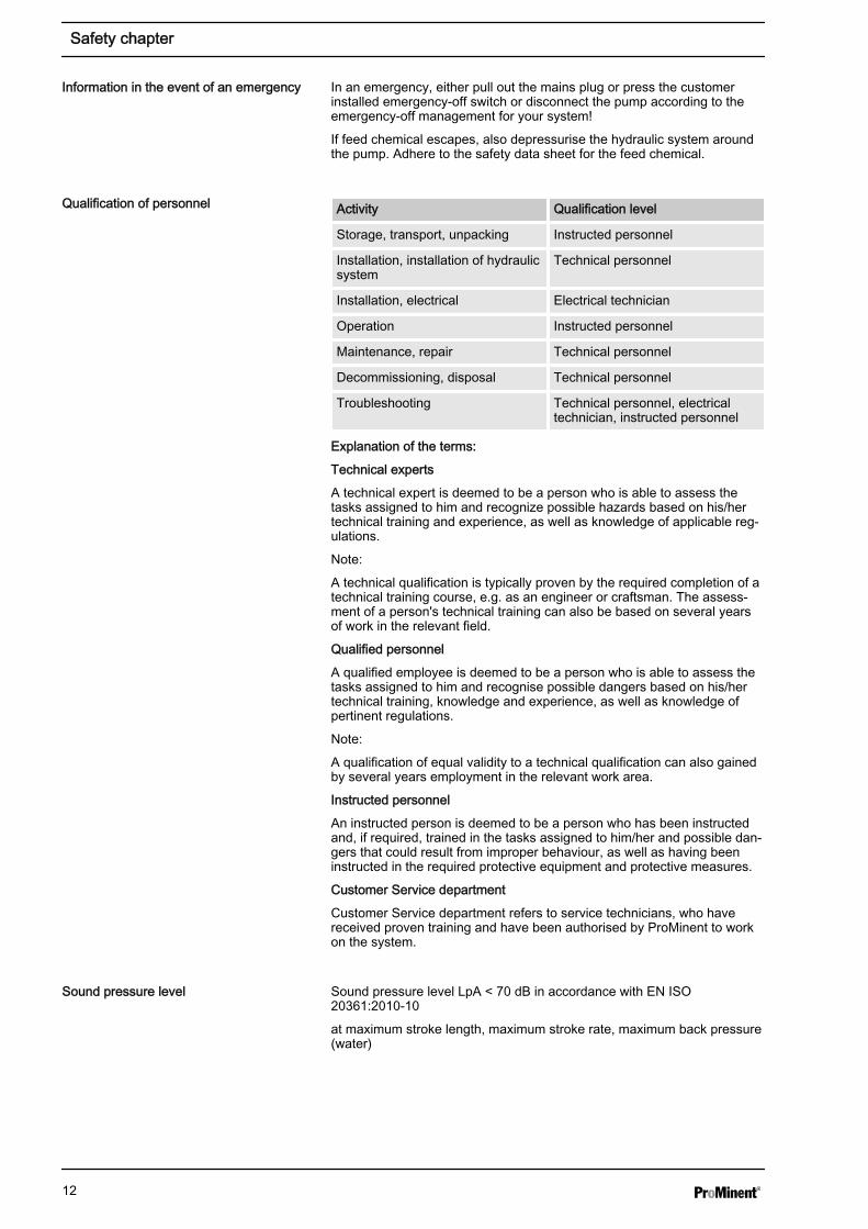
In an emergency, either pull out the mains plug or press the customerinstalled emergency-off switch or disconnect the pump according to theemergency-off management for your system!
If feed chemical escapes, also depressurise the hydraulic system aroundthe pump. Adhere to the safety data sheet for the feed chemical.
Activity Qualification level
Storage, transport, unpacking Instructed personnel
Installation, installation of hydraulicsystem
Technical personnel
Installation, electrical Electrical technician
Operation Instructed personnel
Maintenance, repair Technical personnel
Decommissioning, disposal Technical personnel
Troubleshooting Technical personnel, electricaltechnician, instructed personnel
Explanation of the terms:
Technical experts
A technical expert is deemed to be a person who is able to assess thetasks assigned to him and recognize possible hazards based on his/hertechnical training and experience, as well as knowledge of applicable reg‐ulations.
Note:
A technical qualification is typically proven by the required completion of atechnical training course, e.g. as an engineer or craftsman. The assess‐ment of a person's technical training can also be based on several yearsof work in the relevant field.
Qualified personnel
A qualified employee is deemed to be a person who is able to assess thetasks assigned to him and recognise possible dangers based on his/hertechnical training, knowledge and experience, as well as knowledge ofpertinent regulations.
Note:
A qualification of equal validity to a technical qualification can also gainedby several years employment in the relevant work area.
Instructed personnel
An instructed person is deemed to be a person who has been instructedand, if required, trained in the tasks assigned to him/her and possible dan‐gers that could result from improper behaviour, as well as having beeninstructed in the required protective equipment and protective measures.
Customer Service department
Customer Service department refers to service technicians, who havereceived proven training and have been authorised by ProMinent to workon the system.
Sound pressure level LpA < 70 dB in accordance with EN ISO20361:2010-10
at maximum stroke length, maximum stroke rate, maximum back pressure(water)
Information in the event of an emergency
Qualification of personnel
Sound pressure level
Safety chapter
12

4 Storage, transport and unpacking
WARNING!The transporting of pumps which have been used with radio‐active feed chemicals is forbidden!
They will also not be accepted by ProMinent!
WARNING!Only return the metering pump for repair in a cleaned stateand with a flushed liquid end - refer to the section on decom‐missioning!
Only send metering pumps with a filled in DecontaminationDeclaration form. The Decontamination Declaration consti‐tutes an integral part of an inspection / repair order. A unitcan only be inspected or repaired if a Decontamination Dec‐laration is submitted that has been completed correctly andin full by an authorised and qualified person on behalf of thepump operator.
The "Decontamination Declaration" form can be found in theGeneral Operating Instructions or underwww.prominent.com.
CAUTION!Danger of material damageThe device can be damaged by incorrect or improper storageor transportation!
– The unit should only be stored or transported in a wellpackaged state - preferably in its original packaging.
– The packaged unit should also only be stored or trans‐ported in accordance with the stipulated storage condi‐tions.
– The packaged unit should be protected from moistureand the ingress of chemicals.
Personnel: n Technical personnel
Data Value Unit
Minimum storage and transport tempera‐ture
-20 °C
Maximum storage and transport tempera‐ture
+60 °C
Maximum air humidity * 95 % rel.humidity
* non-condensing
Safety information
Ambient conditions
Storage, transport and unpacking
13

Compare the delivery note with the scope of supply:
n Metering pump with mains power cablen Connector kit for hose/pipe connectionn Product-specific operating instructions with EC Declaration of Con‐
formityn CD with order information, exploded diagrams and data sheetsn Optional accessories if ordered
Scope of supply
Storage, transport and unpacking
14

5 Overview of the Device and Control Elements5.1 Overview of the Device
1 2 3
P_BE_0013_SW
Fig. 2: Complete overview1 Control unit2 Drive Unit3 Liquid End
a
bc
d
e
f
P_BE_0008_SW
Fig. 3: Overview of liquid end (PV)a Discharge valveb Backplatec Dosing headd Bleed valvee Bypass tube nozzlef Suction valve
Overview of the Device and Control Elements
15

5.2 Control Elements
12345
7
89
6
P_BE_0011_SW
Fig. 41 Pulse Control Switch2 Stroke Length Adjustment Knob3 Fault indicator (red)4 Warning indicator (yellow)5 Operating indicator (green)6 Multifunctional Switch7 "External Control" Terminal8 Relay connection (optional)9 "Level Switch" Terminal
5.2.1 Pulse Control SwitchIn the Extern Contact operating mode, either a series of strokes can betriggered or an inbound series of contacts can be stepped down via thepulse control switch by a single contact (on the "external control" terminal).
5.2.2 Stroke Length Adjustment KnobThe stroke length adjustment knob can be used to adjust the strokelength.
5.2.3 Multifunctional SwitchThe multifunctional switch can be used to set the following functions, oper‐ating modes and stroke rate.
The operating modes that can be set are:
n Test (priming function)n Stopn Extern (Contact)n Manual (setting stroke rate in 10 % increments)
Overview of the Device and Control Elements
16

5.2.4 Functional and Fault IndicatorsThe fault indicator lights up if the fluid level in the chemical feed containerfalls below the second switching point of the level switch (20 mm residualfilling level in the chemical feed container).
This LED flashes in the event of an undefined operating mode.
The warning indicator lights up if the fluid level in the chemical feed con‐tainer falls below the first switching point of the level switch.
The operating indicator lights up if the pump is ready for operation andthere are no fault or warning alerts. It goes out quickly as soon as thepump has performed a stroke.
5.2.5 "External Control" TerminalThe "external control" terminal is a five-pole panel terminal.
It enables the following functions and operating modes to be used:
n Pausen Extern Contactn Auxiliary frequency (external frequency changeover)
The two- and four-pole cables used to date can continue tobe used. The "Auxiliary frequency" function can, however,only be used with a five-pole cable.
5.2.6 "Level Switch" TerminalA 2-stage level switch with pre-warning and end switch-off can be con‐nected.
Fault indicator (red)
Warning indicator (yellow)
Operating indicator (green)
Overview of the Device and Control Elements
17

6 Functional description6.1 Liquid End
The dosing process is performed as follows: The diaphragm is pressedinto the dosing head; the pressure in the dosing head closes the suctionvalve and the feed chemical flows through the discharge valve out of thedosing head. The diaphragm is now drawn out of the dosing head; the dis‐charge valve closes due to the negative pressure in the dosing head andfresh feed chemical flows through the suction valve into the dosing head.One cycle is completed.
6.2 Drive UnitThe diaphragm is driven by an electromagnet, which is controlled by anelectronic controller.
6.3 CapacityThe capacity is determined by the stroke length and the stroke rate.
The stroke length is adjusted by the stroke length adjustment knob withina range of 0 ... 100 %. A stroke length of between 30 ... 100 % (SEK type:50 ... 100 %) is recommended to achieve the specified reproducibility!
Data Value Unit
Recommended stroke length, standardtype
30 ... 100 %
Recommended stroke length, SEK type 50 ... 100 %
The stroke rate can be set within a range of 10 ... 100 % using the multi‐functional switch.
6.4 Self-BleedingSelf-bleeding liquid ends (SEK types) are capable of independent primingwhen a discharge line is connected and diverting existent air pockets via abypass. During operation they are also capable of conveying away gaseswhich are produced, independently of the operating pressure in thesystem. It is also possible to dose precisely in a depressurised state dueto the integral back pressure valve.
6.5 Operating ModesThe operating modes are selected by means of the multifunctional switch.
As soon as the stroke rate has been set by the multifunctional switch, thepump finds itself in "Manual" operating mode. 100 % corresponds to 180strokes/min.
The "Extern" operating mode is described below in the "Operation"chapter.
6.6 FunctionsThe functions are described below in the "Operation" chapter.
"Manual" operating mode
"Extern" operating mode:
Functional description
18

6.7 RelayThe pump has two connecting options.
The relay can switch a connected power circuit (e.g. for an alarm horn) inthe event of warnings or fault messages (e.g. warning levels).
The relay can be retrofitted with the retrofit kit via a knock-out opening inthe pump foot - refer to "Retrofitting relays".
This combined relay can generate a contact with each stroke via its pacingrelay in addition to its function as a fault indicating relay.
The relay can be retrofitted with the retrofit kit via a knock-out opening inthe pump foot - refer to "Retrofitting relays".
6.8 Hierarchy of Operating Modes, Functions and Fault StatusesThe different operating modes, functions and fault statuses have a dif‐ferent effect on if and how the pump reacts.
The following list shows the order:
1. - Test (priming)
2. - Fault, Stop, Pause
3. - Auxiliary frequency (external frequency changeover)
4. - Manual, Extern Contact
Comments:
re 1 - "Priming" can take place in any mode of the pump (providing it isfunctioning).
re 2 - "Fault", "Stop" und "Pause" stop everything apart from "Priming".
re 3 - The stroke rate of "Auxiliary frequency" always has priority over thestroke rate specified by an operating mode in 4.
Fault indicating relay option
Fault indicating and pacing relay option
Functional description
19

7 Assembly
WARNING!Risk of electric shockIf water or other electrically conducting liquids penetrate intothe drive housing, an electric shock may occur.
– Position the pump so that drive housing cannot beflooded.
CAUTION!Danger from incorrectly operated or inadequately maintainedpumpsDanger can arise from a poorly accessible pump due toincorrect operation and poor maintenance.
– Ensure that the pump is accessible at all times.– Adhere to the maintenance intervals.
Capacity too lowThe liquid end valves can be disrupted by vibrations.– Secure the metering pump so that no vibrations can
occur.
Capacity too lowIf the valves of the liquid end do not stand vertically upwards,they cannot close correctly.– Suction and discharge valves must stand vertically
upwards (for self-bleeding liquid end, the bleed valve).
Mount the metering pump with the pump foot on a horizontal, leveland load-bearing supporting surface.
Assembly
20

8 Installation, hydraulic
CAUTION!Warning of feed chemical spraying aroundAn unsuitable feed chemical can damage the parts of thepump contacted by the chemical.
– Take into account the resistance of the material con‐tacted by the chemical when selecting the feed chemical- refer to the ProMinent ® resistance list in the productequipment catalogue or at www.prominent.com.
CAUTION!Warning of feed chemical spraying aroundPumps which are not fully installed hydraulically can ejectfeed chemicals from the outlet openings of the dischargevalves as soon as they are connected to the mains.
– The pump must first be hydraulically installed and thenelectrically.
– In the event that you have failed to do so, press the[STOP/START] button or press the emergency-stopswitch.
CAUTION!Warning of feed chemical spraying aroundFeed chemical can spray out of the hydraulic components ifthey are manipulated or opened due to pressure in the liquidend and adjacent parts of the system.
– Disconnect the pump from the mains power supply andensure that it cannot be switched on again by unauthor‐ised persons.
– Depressurise the system before commencing any workon hydraulic parts.
CAUTION!Danger from rupturing hydraulic componentsPeak loads during the dosing stroke can cause the maximumpermissible operating pressure of the system and pump tobe exceeded.
– The discharge lines are to be properly designed.
CAUTION!Danger of personal and material damageThe use of untested third party parts can result in damage topersonnel and material damage.
– Only fit parts to dosing pumps, which have been testedand recommended by ProMinent.
CAUTION!Warning of illegal operationObserve the regulations that apply where the unit is to beinstalled.
Safety information
Installation, hydraulic
21
8.1 Install hose lines
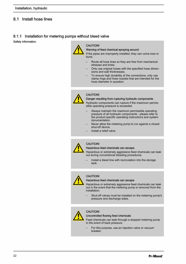
8.1.1 Installation for metering pumps without bleed valve
CAUTION!Warning of feed chemical spraying aroundIf the pipes are improperly installed, they can come lose orburst.
– Route all hose lines so they are free from mechanicalstresses and kinks.
– Only use original hoses with the specified hose dimen‐sions and wall thicknesses.
– To ensure high durability of the connections, only useclamp rings and hose nozzles that are intended for thehose diameter in question.
CAUTION!Danger resulting from rupturing hydraulic componentsHydraulic components can rupture if the maximum permis‐sible operating pressure is exceeded.
– Always maintain the maximum permissible operatingpressure of all hydraulic components - please refer tothe product specific operating instructions and systemdocumentation.
– Never allow the metering pump to run against a closedshut-off device.
– Install a relief valve.
CAUTION!Hazardous feed chemicals can escapeHazardous or extremely aggressive feed chemicals can leakout during conventional bleeding procedures.
– Install a bleed line with recirculation into the storagetank.
CAUTION!Hazardous feed chemicals can escapeHazardous or extremely aggressive feed chemicals can leakout in the event that the metering pump is removed from theinstallation.
– Shut-off valves must be installed on the metering pump'spressure and discharge sides.
CAUTION!Uncontrolled flowing feed chemicalsFeed chemicals can leak through a stopped metering pumpin the event of back pressure.
– For this purpose, use an injection valve or vacuumbreaker.
Safety information
Installation, hydraulic
22

CAUTION!Uncontrolled flowing feed chemicalsFeed chemicals can leak through the metering pump in anuncontrolled manner in the event of excessive priming pres‐sure.
– The maximum priming pressure for the metering pumpmay not be exceeded - please refer to the product-spe‐cific operating instructions.
The pipes are to be aligned in such a way as the meteringpump and the liquid end can be removed from the side, ifnecessary.
1. Cut off the ends of the hoses straight.
2. Pull the union nut (2) and clamp ring (3) over the hose (1) - seefigure .
3. Push the hose end (1) up to the stop over the nozzle (4). Widen it, ifnecessary.
Ensure that the O-ring and flat seal (5) is properlyfitted to the valve (6).
Used PTFE seals may never be re-used. An installa‐tion sealed in this way will not be watertight.The reason for this is that this type of seal is perma‐nently distorted when subjected to pressure.
In order to enable it to be distinguished from theEPDM flat seal, the FPM flat seal design PV has a dot.
4. Place the hose (1) with the nozzle (4) onto the valve (6).
5. Clamp the hose connector: Screw the union nut (2) tight whilesimultaneously pressing on the hose (1).
6. Re-tighten the hose connector: Pull on the hose (1) briefly, which isfastened to the dosing head, and tighten up the union nut (2) oncemore.
Install hose lines - design PP, NP, PV, TT
Installation, hydraulic
23

1 Hose2 Union nut3 Clamp ring4 Nozzle5 O-ring and flat seal6 Valve
1. Pull the union nut (2) and clamp rings (3, 4) over the pipe (1) withapprox. 10 mm overhang - see .
2. Insert the pipe (1) up to the stop in the valve (5).
3. Tighten the union nut (2).
1 Pipe2 Union nut3 Rear clamp ring4 Front clamp ring5 Valve
CAUTION!Warning of feed chemical spraying aroundConnections can come free in the event that hose lines areinstalled incorrectly on stainless steel valves.
– Only use PE or PTFE hose lines.– In addition, insert a stainless steel support insert into the
hose line.
8.1.2 Installation for metering pumps with bleed valve
CAUTION!– All of the installation and safety notes for metering
pumps without bleed valves also apply.
A return line is connected in addition to the suction and discharge lines.
1. Fasten the hose pipe to the return line tube nozzle or to the liquidend bleed valve. PVC hose, soft, 6x4 mm is recommended for this.
2. Feed the free end of the return line back to the storage tank.
1
2
4
5
6
3
P_MAZ_0021_SW
Fig. 5: Designs PP, NP, PV, TT
Installing stainless steel pipe - design SS
1
2
4
5
3
P_MAZ_0022_SW
Fig. 6: Design SS
Installing hose lines - design SS
Safety information
Installation of the return line
Installation, hydraulic
24
3. Shorten the return line hose so that it cannot submerge into the feedchemical in the storage tank.
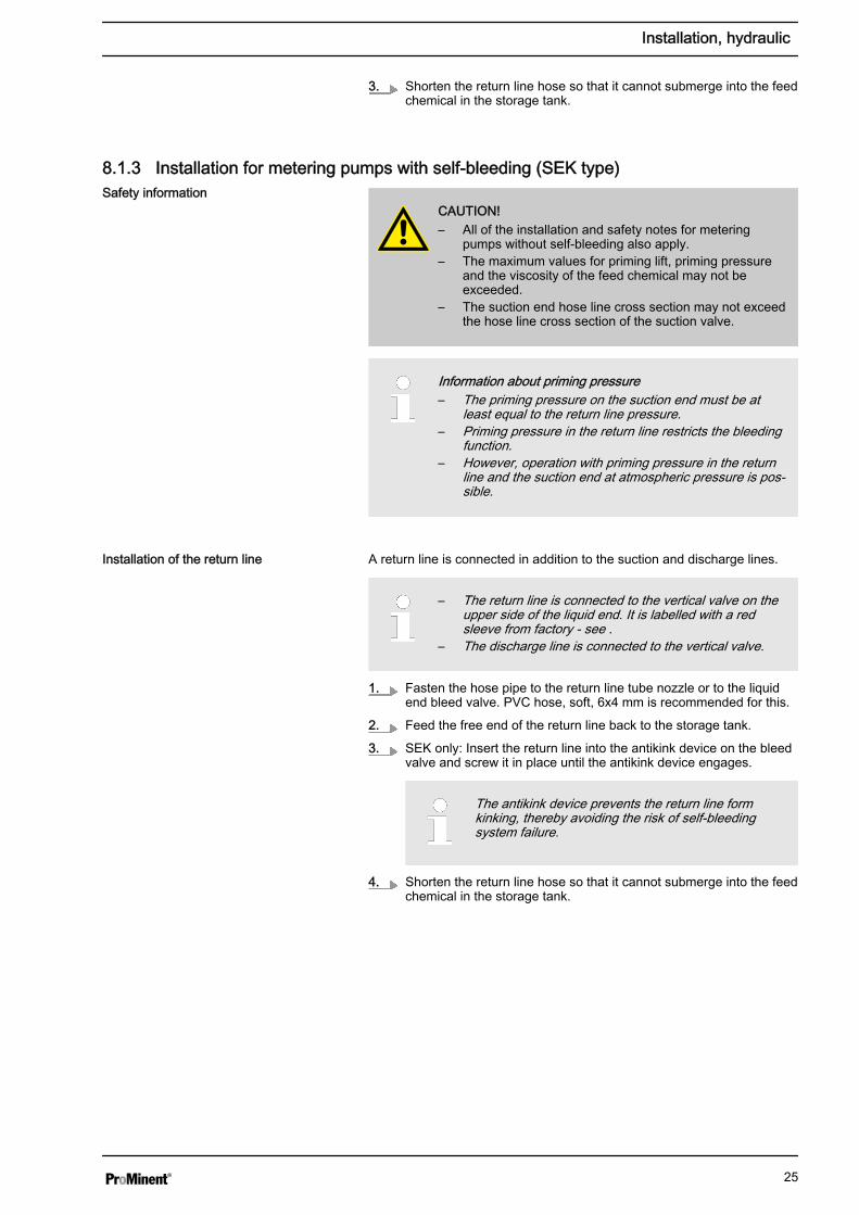
8.1.3 Installation for metering pumps with self-bleeding (SEK type)
CAUTION!– All of the installation and safety notes for metering
pumps without self-bleeding also apply.– The maximum values for priming lift, priming pressure
and the viscosity of the feed chemical may not beexceeded.
– The suction end hose line cross section may not exceedthe hose line cross section of the suction valve.
Information about priming pressure– The priming pressure on the suction end must be at
least equal to the return line pressure.– Priming pressure in the return line restricts the bleeding
function.– However, operation with priming pressure in the return
line and the suction end at atmospheric pressure is pos‐sible.
A return line is connected in addition to the suction and discharge lines.
– The return line is connected to the vertical valve on theupper side of the liquid end. It is labelled with a redsleeve from factory - see .
– The discharge line is connected to the vertical valve.
1. Fasten the hose pipe to the return line tube nozzle or to the liquidend bleed valve. PVC hose, soft, 6x4 mm is recommended for this.
2. Feed the free end of the return line back to the storage tank.
3. SEK only: Insert the return line into the antikink device on the bleedvalve and screw it in place until the antikink device engages.
The antikink device prevents the return line formkinking, thereby avoiding the risk of self-bleedingsystem failure.
4. Shorten the return line hose so that it cannot submerge into the feedchemical in the storage tank.
Safety information
Installation of the return line
Installation, hydraulic
25

P_MAZ_0023_SW
1
23
4
5
Fig. 7: SEK liquid end1 Antikink device2 Bleed valve for the return line in the storage tank, 6/4 mm3 Red sleeve4 Discharge valve for discharge line to injection point, 6/4 - 12/9 mm5 Suction valve for suction line in storage tank, 6/4 - 12/9 mm
Installation, hydraulic
26

9 Electrical installation
WARNING!Danger of electric shockA mains voltage may exist inside the device.
– Before any work, disconnect the device's mains cablefrom the mains.
WARNING!Risk of electric shockThis pump is supplied with a grounding conductor and agrounding-type attachment plug.
– To reduce the risk of electric shock, ensure that it is con‐nected only to a proper grounding-type receptacle.
WARNING!Risk of electric shockIn the event of an electrical accident, the pump must bequickly disconnected from the mains.
– Install an emergency cut-off switch in the pump powersupply line or
– Integrate the pump in the emergency cut-off manage‐ment of the system and inform personnel of the isolatingoption.
WARNING!Danger of electric shockA mains voltage may exist inside the pump housing.
– If the pump housing has been damaged, you must dis‐connect it from the mains immediately. It may only bereturned to service after an authorised repair.
CAUTION!Material damage possible due to power surgesShould the pump be connected to the mains power supply inparallel to inductive consumers (such as solenoid valves,motors), inductive power surges can damage the controllerwhen it is switched off.
– Provide the pump with its own contacts and supply withvoltage via a contactor relay or relay.
Personnel: n Electrician
Install the pump technically correctly and in accordance with theoperating instructions and applicable regulations.
Electrical installation
27

9.1 Supply voltage connection
WARNING!Unexpected startup is possibleAs soon as the pump is connected to the mains, the pumpmay start pumping and consequently feed chemical mayescape.
– Prevent dangerous feed chemicals from escaping.– If you have not successfully prevented this, immediately
press the [STOP/START] key or disconnect the pumpfrom mains, e.g. via an emergency cu-off switch.
CAUTION!If the pump is integrated into a system: The system must bedesigned so that potential hazardous situations are avoidedby pumps starting up automatically subsequent to unin‐tended power interruptions.
Connect the pump to the mains power supply using the mains cable.
Should the pump be connected to the mains in parallel to inductive con‐sumers (e.g. solenoid valves, motor), the pump must be electrically iso‐lated when these consumers are switched off.
n Supply the pumps with voltage via a contactor relay or relay usingseparate contacts for the pump.
n If this is not possible then connect a varistor (part no. 710912) or anRC member, 0.22 µF / 220 Ω in parallel.
Product Part no.
Varistor: 710912
RC Gate, 0.22 µF / 220 Ω: 710802
9.2 Description of the Terminals9.2.1 "External Control" Terminal
The "external control" terminal is a five-pole panel terminal. It is compatiblewith two- and four-pole cables.
The "Auxiliary Frequency" function can only be used with a five-pole cable.
Electrical interface for pin 1 "Pause" - pin 2 "Extern Contact" - pin 5 "Auxil‐iary frequency"
Data Value Unit
Voltage with open contacts 5 V
Input resistance 10 kΩ
Max. pulse frequency 25 pulse/s
Minimum pulse duration 20 ms
Activation via:
n zero volt connection contact (load: 0.5 mA at 5 V) orn semi-conductor switch (residual voltage < 0.7 V)
Parallel connection to inductive con‐sumers
Interference suppression aids
1
54
2
3
P_BE_0014_SW
Fig. 8: Assignment on the pump
Electrical installation
28
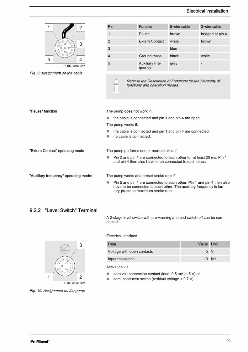
Pin Function 5-wire cable 2-wire cable
1 Pause brown bridged at pin 4
2 Extern Contact white brown
3 - blue -
4 Ground mass black white
5 Auxiliary Fre‐quency
grey -
Refer to the Description of Functions for the hierarchy offunctions and operation modes.
The pump does not work if:
n the cable is connected and pin 1 and pin 4 are open.
The pump works if:
n the cable is connected and pin 1 and pin 4 are connected.n no cable is connected.
The pump performs one or more strokes if:
n Pin 2 and pin 4 are connected to each other for at least 20 ms. Pin 1and pin 4 then also have to be connected to each other.
The pump works at a preset stroke rate if:
n Pin 5 and pin 4 are connected to each other. Pin 1 and pin 4 then alsohave to be connected to each other. The auxiliary frequency is fac‐tory-preset to maximum stroke rate.
9.2.2 "Level Switch" TerminalA 2-stage level switch with pre-warning and end switch-off can be con‐nected.
Electrical interface
Data Value Unit
Voltage with open contacts 5 V
Input resistance 10 kΩ
Activation via
n zero volt connection contact (load: 0.5 mA at 5 V) orn semi-conductor switch (residual voltage < 0.7 V)
2
45
1
3
P_BE_0015_SW
Fig. 9: Assignment on the cable
"Pause" function
"Extern Contact" operating mode
"Auxiliary frequency" operating mode:
3
21P_BE_0016_SW
Fig. 10: Assignment on the pump
Electrical installation
29
Pin Function 3-wire cable
1 Ground mass black
2 Minimum pre-warning blue
3 Minimum end switch-off
brown
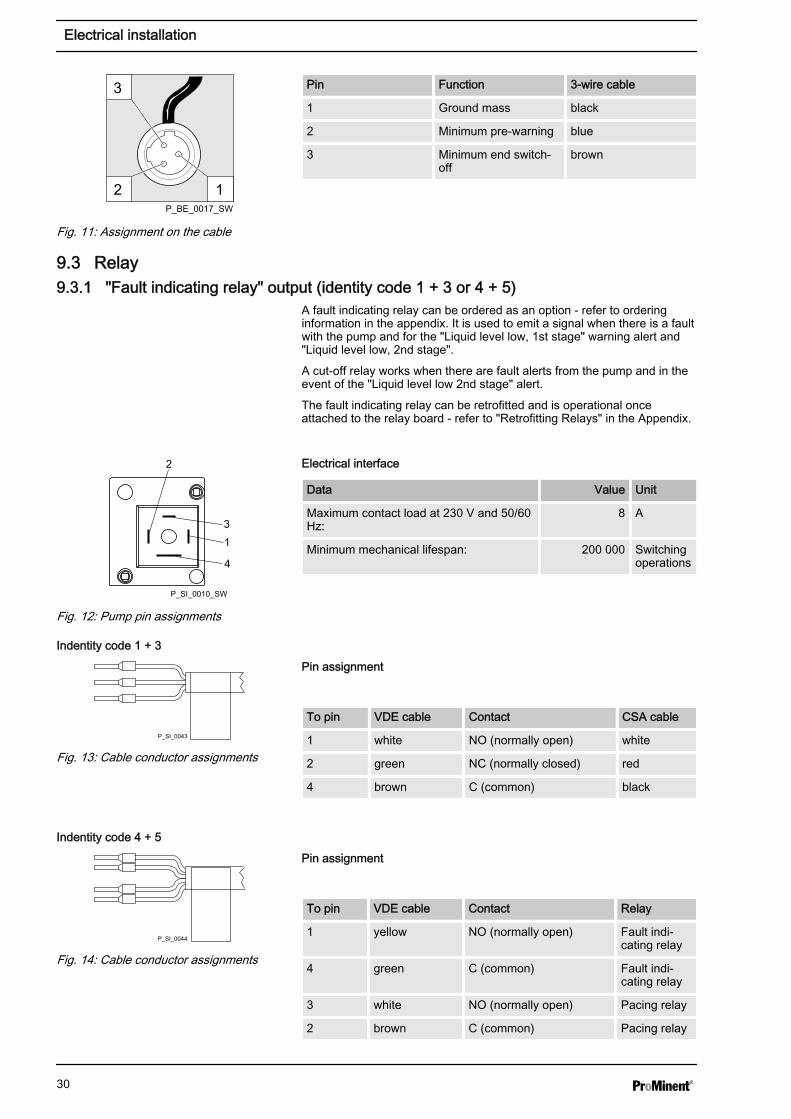
9.3 Relay9.3.1 "Fault indicating relay" output (identity code 1 + 3 or 4 + 5)
A fault indicating relay can be ordered as an option - refer to orderinginformation in the appendix. It is used to emit a signal when there is a faultwith the pump and for the "Liquid level low, 1st stage" warning alert and"Liquid level low, 2nd stage".
A cut-off relay works when there are fault alerts from the pump and in theevent of the "Liquid level low 2nd stage" alert.
The fault indicating relay can be retrofitted and is operational onceattached to the relay board - refer to "Retrofitting Relays" in the Appendix.
Electrical interface
Data Value Unit
Maximum contact load at 230 V and 50/60Hz:
8 A
Minimum mechanical lifespan: 200 000 Switchingoperations
Pin assignment
To pin VDE cable Contact CSA cable
1 white NO (normally open) white
2 green NC (normally closed) red
4 brown C (common) black
Pin assignment
To pin VDE cable Contact Relay
1 yellow NO (normally open) Fault indi‐cating relay
4 green C (common) Fault indi‐cating relay
3 white NO (normally open) Pacing relay
2 brown C (common) Pacing relay
3
12P_BE_0017_SW
Fig. 11: Assignment on the cable
2
31
4
P_SI_0010_SW
Fig. 12: Pump pin assignments
Indentity code 1 + 3
P_SI_0043
Fig. 13: Cable conductor assignments
Indentity code 4 + 5
P_SI_0044
Fig. 14: Cable conductor assignments
Electrical installation
30

9.3.2 Output pacing relay (identity code 4 + 5)A fault indicating and a pacing relay can optionally be ordered - refer toordering information in the appendix. The pacing output is electrically-iso‐lated by means of an optocoupler with a semiconductor switch. Thesecond switch is a relay.
The fault indicating/pacing relay can be retrofitted and is operational onceattached to the relay board - refer to "Retrofitting Relays" in the Appendix.
Electrical interface
for semiconductor switch pacing relay:
Data Value Unit
Residual voltage max. at Ic = 1 mA 0.4 V
Maximum current 100 mA
Maximum voltage 24 VDC
Pacing pulse duration, approx. 100 ms
Pin assignment
To pin VDE cable Contact Relay
1 yellow NO (normally open) Fault indi‐cating relay
4 green C (common) Fault indi‐cating relay
3 white NO (normally open) Pacing relay
2 brown C (common) Pacing relay
2
31
4
P_SI_0010_SW
Fig. 15: Pump pin assignments
Indentity code 4 + 5
P_SI_0044
Fig. 16: Cable conductor assignments
Electrical installation
31
10 Operation
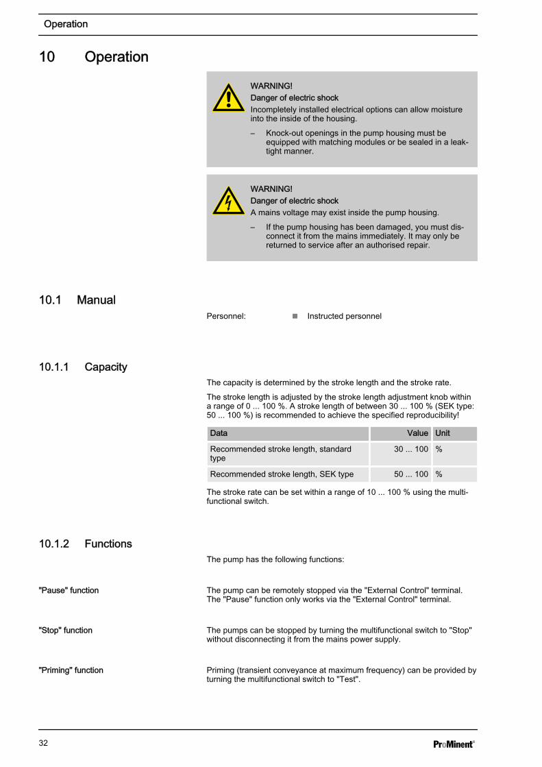
WARNING!Danger of electric shockIncompletely installed electrical options can allow moistureinto the inside of the housing.
– Knock-out openings in the pump housing must beequipped with matching modules or be sealed in a leak-tight manner.
WARNING!Danger of electric shockA mains voltage may exist inside the pump housing.
– If the pump housing has been damaged, you must dis‐connect it from the mains immediately. It may only bereturned to service after an authorised repair.
10.1 ManualPersonnel: n Instructed personnel
10.1.1 CapacityThe capacity is determined by the stroke length and the stroke rate.
The stroke length is adjusted by the stroke length adjustment knob withina range of 0 ... 100 %. A stroke length of between 30 ... 100 % (SEK type:50 ... 100 %) is recommended to achieve the specified reproducibility!
Data Value Unit
Recommended stroke length, standardtype
30 ... 100 %
Recommended stroke length, SEK type 50 ... 100 %
The stroke rate can be set within a range of 10 ... 100 % using the multi‐functional switch.
10.1.2 FunctionsThe pump has the following functions:
The pump can be remotely stopped via the "External Control" terminal.The "Pause" function only works via the "External Control" terminal.
The pumps can be stopped by turning the multifunctional switch to "Stop"without disconnecting it from the mains power supply.
Priming (transient conveyance at maximum frequency) can be provided byturning the multifunctional switch to "Test".
"Pause" function
"Stop" function
"Priming" function
Operation
32

Information about the liquid/powder level in the feed chemical container isreported to the pump. To do so, a two-stage level switch must be fitted; itis connected to the "Level switch" terminal.
Enables switching of a stroke rate via the "External control" jack. This aux‐iliary frequency has priority over the operating mode stroke rate settings .In the standard version, the "Auxiliary frequency" function is programmedto 100 % stroke rate.
10.1.3 External contactIn the Extern Contact operating mode, either a series of strokes can betriggered or an inbound series of contacts can be stepped down via thepulse control switch by a single contact on the "External control" terminal.To do so, the multifunctional switch has to be turned to "Extern".
Explanation of the stepped-down values:
Settable values Incoming contacts Strokes performed
1:1 1 1
1:2 2 1
1:4 4 1
1:8 8 1
1:16 16 1
1:32 32 1
1:64 64 1
Explanation of stepped-up values:
Settable values Incoming contacts Strokes performed
1:1 1 1
2:1 1 2
4:1 1 4
8:1 1 8
16:1 1 16
32:1 1 32
64:1 1 64
10.2 Remote operationThere is an option to control the pump remotely via a signal cable - refer toyour system documentation and to "Electrical Installation".
"Level switch" function
"Auxiliary rate" function
"Extern" operating mode:
Operation
33

11 Maintenance
WARNING!It is mandatory that you read the safety information andspecifications in the "Storage, Transport and Unpacking"chapter prior to shipping the pump.
CAUTION!Warning of feed chemical spraying aroundFeed chemical can spray out of the hydraulic components ifthey are manipulated or opened due to pressure in the liquidend and adjacent parts of the system.
– Disconnect the pump from the mains power supply andensure that it cannot be switched on again by unauthor‐ised persons.
– Depressurise the system before commencing any workon hydraulic parts.
Further data on CDAll product-specific operating instructions include a CD withorder details, exploded diagrams and dimensions sheets, ifthey are not included in the operating instructions.
Interval Maintenance work Personnel
Quarterly* n Check the metering diaphragm for damage** - refer to "Repair".n Check that the hydraulic lines are fixed firmly to the liquid end.n Check that the suction valve and discharge valve are correctly seated.n Check the tightness of the entire liquid end - particularly around the
leakage hole - please refer to Fig. 17!n Check that the flow is correct: Allow the pump to prime briefly - turn the
multifunctional switch briefly to "Test"n Check that the electrical connections are intactn Check the integrity of the housing.n Check that the dosing head screws are tight
Technical personnel
* Under normal loading (approx. 30 % of continuous operation)
Under heavy loading (e.g. continuous operation): Shorter intervals.
** For feed chemicals which particularly load the diaphragm, e.g. thosecontaining abrasive additives, check the diaphragm frequently.
Standard liquid ends:
Maintenance
34
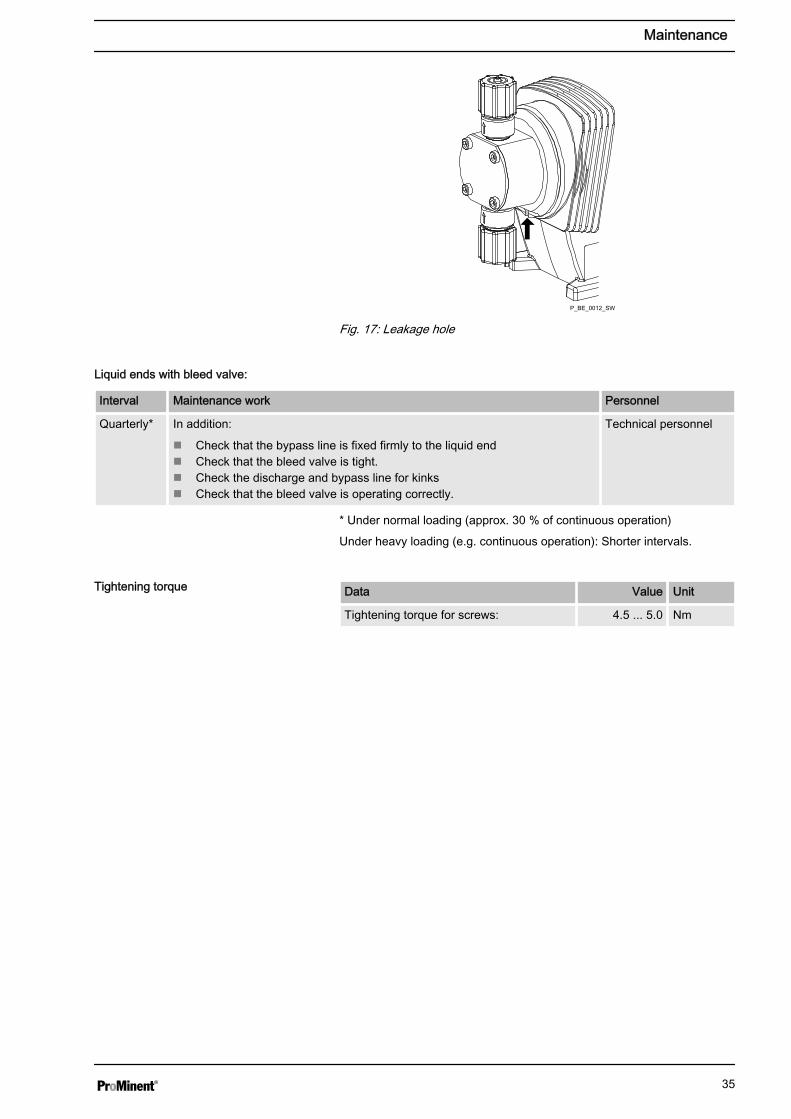
P_BE_0012_SW
Fig. 17: Leakage hole
Interval Maintenance work Personnel
Quarterly* In addition:
n Check that the bypass line is fixed firmly to the liquid endn Check that the bleed valve is tight.n Check the discharge and bypass line for kinksn Check that the bleed valve is operating correctly.
Technical personnel
* Under normal loading (approx. 30 % of continuous operation)
Under heavy loading (e.g. continuous operation): Shorter intervals.
Data Value Unit
Tightening torque for screws: 4.5 ... 5.0 Nm
Liquid ends with bleed valve:
Tightening torque
Maintenance
35

12 Repairs
WARNING!Danger of an electric shockUnauthorised repairs inside the pump can result in an elec‐tric shock.
For this reason repairs inside the pump may only be per‐formed by a ProMinent subsidiary or representative, in partic‐ular the following:
– Replacement of damaged mains connection lines– Replacement of fuses– Replacement of electronic control
WARNING!It is mandatory that you read the safety information andspecifications in the "Storage, Transport and Unpacking"chapter prior to shipping the pump.
WARNING!Contact with the feed chemicalParts that come into contact with the feed chemical areuncovered and handled during overhaul work.
– Protect yourself against the feed chemical in case it ishazardous. Read the safety data sheet on the feedchemical.
CAUTION!Warning of feed chemical spraying aroundFeed chemical can spray out of the hydraulic components ifthey are manipulated or opened due to pressure in the liquidend and adjacent parts of the system.
– Disconnect the pump from the mains power supply andensure that it cannot be switched on again by unauthor‐ised persons.
– Depressurise the system before commencing any workon hydraulic parts.
12.1 Cleaning valvesPersonnel: n Technical personnel
Warning of faulty operationThe exploded views in the Appendix should be referred towhen working on the unit.
Safety information
Repairs
36

Warning of faulty operation– Discharge and suction valves differ from each other!
Only take them apart one after each other, so that youdo not confuse the components!
– Only use new components which fit your valve - both interms of shape and chemical resistance!
– Recalibrate the pump after replacing a valve!– Using an Allen key or similar, insert it into the smaller
hole of the discharge connector and push the valveinserts out of it.
A suction valve is constructed in almost the same way as a dischargevalve.
Please note, however, that:
n the two valve inserts are identical heren There is an additional spacer between the valve inserts.n There is a shaped seal in the dosing head instead of an O-ring.n The flow direction of the suction connector is the opposite of that of
the discharge connector.
Warning of faulty operation– Discharge and suction valves differ from each other!
Only take them apart one after each other, so that youdo not confuse the components!
– Only use new components which fit your valve - both interms of shape and chemical resistance!
– On the PVT material version, the ball seat is integratedin the dosing head and so has to be cleaned separately!
– On the PVT material version, the discharge valve is adouble ball valve!
– Using an Allen key or similar, insert it into the smallerhole of the discharge connector and push the valveinserts out of it.
A suction valve is constructed in almost the same way as a dischargevalve.
Please note, however, that:
n The flow direction of the suction connector is the opposite of that ofthe discharge connector.
Cleaning a discharge valve or a suctionvalve on types (PP, PV, NP) 1000, 1601,1602, 1604, 2504
Cleaning a discharge valve or a suctionvalve on types (PP, PV, NP) 0708, 1008,0220, 0420, 0413, 0713, 0232
Repairs
37

12.2 Replacing the metering diaphragm
WARNING!A few cubic centimetres of feed chemical may have accumu‐lated behind the metering diaphragm in the backplate fol‐lowing a leak - depending on the design!
– Take this feed chemical into consideration when you areplanning a repair - especially if it is hazardous!
Personnel: n Technical personnel
n If necessary take protective measures.n Observe the safety data sheet for the feed chemical.n Depressurise the system.
1. Empty the liquid end (turn the liquid end upside down and allow thefeed chemical to run out; flush out with a suitable medium; flush theliquid end thoroughly when using hazardous feed chemicals!)
2. Turn the stroke adjustment dial until it can go no further at 0 %stroke length if the pump is running (the drive shaft is then difficult toturn).
3. Switch off the pump.
4. Unscrew the hydraulic connectors on the discharge and suctionside.
5. With PP types with bleed valve: Firstly remove the bleed valve (starhandle), then lift off the cover of the liquid end with a screw driver.
6. Remove the screws (1).
7. Loosen the dosing head (2) and the backplate (4) from the pumphousing (6) - but only loosen!
8. Hold the pump housing (6) with one hand and clamp the diaphragm(3) with the other hand between the dosing head (2) and the back‐plate (4).
9. Loosen the diaphragm (3) from the drive axle with a gentle back‐wards turn of the dosing head (2), diaphragm (3) and backplate (4)in an anticlockwise direction.
10. Unscrew the diaphragm (3) completely from the drive shaft.
11. Remove the backplate (4) from the pump housing (6).
12. Check the condition of the safety diaphragm (5) and replace if nec‐essary.
13. Push the safety diaphragm (5) onto the drive axle only until it liesflush with the pump housing (6) and no further!
14. Tentatively screw the new diaphragm (3) onto the drive shaft until itsstop position.
ð The diaphragm (3) is now sitting at the end position of thethread.
15. Should this not work, remove dirt or swarf out of the threads andscrew the diaphragm (3) onto the drive shaft correctly this time.
The diaphragm must be screwed exactly onto thedrive shaft otherwise the pump will subsequently notdose correctly!
16. Unscrew the diaphragm (3) again.
17. Place the backplate (4) onto the pump housing (6).
Repairs
38

CAUTION!Leakage may become apparent at a later stage.– The leakage hole must point downwards when the
pump is installed later - please refer to Fig. 18!– Place the backplate (4) immediately into the cor‐
rect position on the pump housing (6)! Do not twistthe backplate on the pump housing so that thesafety diaphragm (5) becomes warped!
18. Place the diaphragm (3) into the backplate (4).
CAUTION!Leakage may become apparent at a later stage.– Do not overtighten the diaphragm (3) in the fol‐
lowing step!– The backplate (4) must remain in its position so
that the safety diaphragm does not becomewarped!
19. Hold the backplate (4) firmly and screw the diaphragm (3) in a clock‐wise direction until it is sitting tightly (the twisting resistance of thereturn spring can be felt).
20. Set the stroke length to 100 %.
21. Place the dosing head (2) with the screws (1) onto the diaphragm(3) and the backplate (4) - the suction connector must be pointingdownwards when the pump is later installed.
22. Gently tighten the screws (1) and then tighten in a diagonal pattern.See below for tightening torque.
23. With PP types with bleed valve: Allow the cover of the liquid end torest in the dosing head, then press the knob on the bleed valve intothe dosing head.
CAUTION!Leakage possible– Check the tightening torque of the screws after
24-hours of operation!– With PP dosing heads, recheck the tightening
torque again after three months!
Data Value Unit
Tightening torque for screws: 4.5 ... 5.0 Nm
Tightening torque
Repairs
39

1 2 3 4 5 6
P_BE_0018_SW
Fig. 18: Partial exploded view of liquid end
Repairs
40
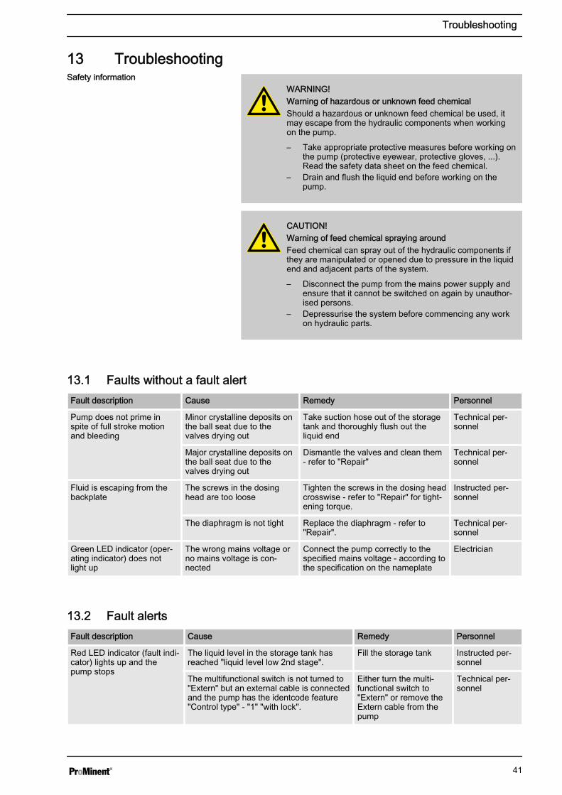
13 Troubleshooting
WARNING!Warning of hazardous or unknown feed chemicalShould a hazardous or unknown feed chemical be used, itmay escape from the hydraulic components when workingon the pump.
– Take appropriate protective measures before working onthe pump (protective eyewear, protective gloves, ...).Read the safety data sheet on the feed chemical.
– Drain and flush the liquid end before working on thepump.
CAUTION!Warning of feed chemical spraying aroundFeed chemical can spray out of the hydraulic components ifthey are manipulated or opened due to pressure in the liquidend and adjacent parts of the system.
– Disconnect the pump from the mains power supply andensure that it cannot be switched on again by unauthor‐ised persons.
– Depressurise the system before commencing any workon hydraulic parts.
13.1 Faults without a fault alertFault description Cause Remedy Personnel
Pump does not prime inspite of full stroke motionand bleeding
Minor crystalline deposits onthe ball seat due to thevalves drying out
Take suction hose out of the storagetank and thoroughly flush out theliquid end
Technical per‐sonnel
Major crystalline deposits onthe ball seat due to thevalves drying out
Dismantle the valves and clean them- refer to "Repair"
Technical per‐sonnel
Fluid is escaping from thebackplate
The screws in the dosinghead are too loose
Tighten the screws in the dosing headcrosswise - refer to "Repair" for tight‐ening torque.
Instructed per‐sonnel
The diaphragm is not tight Replace the diaphragm - refer to"Repair".
Technical per‐sonnel
Green LED indicator (oper‐ating indicator) does notlight up
The wrong mains voltage orno mains voltage is con‐nected
Connect the pump correctly to thespecified mains voltage - according tothe specification on the nameplate
Electrician
13.2 Fault alertsFault description Cause Remedy Personnel
Red LED indicator (fault indi‐cator) lights up and thepump stops
The liquid level in the storage tank hasreached "liquid level low 2nd stage".
Fill the storage tank Instructed per‐sonnel
The multifunctional switch is not turned to"Extern" but an external cable is connectedand the pump has the identcode feature"Control type" - "1" "with lock".
Either turn the multi‐functional switch to"Extern" or remove theExtern cable from thepump
Technical per‐sonnel
Safety information
Troubleshooting
41

13.3 Warning AlertsFault description Cause Remedy Personnel
Yellow LED indicator (warningindicator) lights up
The liquid level in the storage tank hasreached "liquid level low 1st stage".
Fill the storagetank
Instructed personnel
13.4 All Other FaultsPlease contact the responsible ProMinent subsidiary or representative!
Troubleshooting
42

14 Decommissioning
WARNING!Danger from chemical residuesThere is normally chemical residue in the liquid end and onthe housing after operation. This chemical residue could behazardous to people.
– It is mandatory that the safety information relating to the"Storage, transport and unpacking" chapter is readbefore shipping or transporting the unit.
– Thoroughly clean the liquid end and the housing ofchemicals and dirt. Adhere to the safety data sheet forthe feed chemical.
WARNING!Warning of hazardous or unknown feed chemicalShould a hazardous or unknown feed chemical be used, itmay escape from the hydraulic components when workingon the pump.
– Take appropriate protective measures before working onthe pump (protective eyewear, protective gloves, ...).Read the safety data sheet on the feed chemical.
– Drain and flush the liquid end before working on thepump.
CAUTION!Warning of feed chemical spraying aroundFeed chemical can spray out of the hydraulic components ifthey are manipulated or opened due to pressure in the liquidend and adjacent parts of the system.
– Disconnect the pump from the mains power supply andensure that it cannot be switched on again by unauthor‐ised persons.
– Depressurise the system before commencing any workon hydraulic parts.
Danger of damage to the deviceTake into account the information in the "Storage, Transportand Unpacking" chapter if the system is decommissioned fora temporary period.
Personnel: n Technical personnel
1. Disconnect the pump from the mains power supply.
2. Empty the liquid end by turning the pump upside down and allowingthe feed chemical to run out.
3. Flush the liquid end with a suitable medium; flush the dosing headthoroughly when using hazardous feed chemicals!
Decommissioning
Decommissioning
43

CAUTION!Warning of feed chemical spraying aroundFeed chemical can spray out of the hydraulic components ifthey are manipulated or opened due to pressure in the liquidend and adjacent parts of the system.
– Disconnect the pump from the mains power supply andensure that it cannot be switched on again by unauthor‐ised persons.
– Depressurise the system before commencing any workon hydraulic parts.
Personnel: n Technical personnel
CAUTION!Environmental hazard due to electronic wasteThere are electronic components in the pump, which canhave a toxic effect on the environment.
– Separate the electronic components from the remainingparts.
– Note the pertinent regulations currently applicable inyour country!
Disposal
Decommissioning
44

15 Technical data15.1 Performance data
Type Minimum pump capacity
at maximum back pressure
Minimum pump capacity
at medium back pressure
Con‐nectorsize
externalÆ xinternalÆ
Suctionlift*
Priminglift**
Max‐imumprimingpressureon suc‐tion side
bar l/h ml/stroke
bar l/h ml/stroke
mm m WS m WS bar
Beta®
1000 10 0.74 0.069 5.0 0.82 0.076 6x4 6.0 1.8 8
0700 7 0.8 0.074 3.5 0.88 0.074 6x4 6.0 1.8 8
0400 4 0.84 0.078 2.0 0.92 0.078 6x4 6.0 1.8 8
2001 20 0.96 0.089 10 1.5 0.13 6x3 6.0 2.0 8
1601 16 1.1 0.10 8.0 1.40 0.13 6x4 6.0 2.0 8
1001 10 1.3 0.12 5.0 1.5 0.14 6x4 6.0 2.0 8
0701 7 1.4 0.13 3.5 1.7 0.14 6x4 6.0 2.0 8
0401 4 1.5 0.14 2.0 2.0 0.18 6x4 6.0 2.0 8
2002 20 1.7 0.16 10 2.8 0.26 6x3 6.0 2.5 5.5
1602 16 2.2 0.20 8.0 2.5 0.24 6x4 6.0 2.5 5.5
1002 10 2.4 0.22 5.0 2.8 0.26 6x4 6.0 2.5 5.5
0702 7 2.6 0.24 3.5 3.1 0.29 6x4 6.0 2.5 5.5
0402 4 2.8 0.26 2.0 3.6 0.36 6x4 6.0 2.5 5.5
1604 16 3.6 0.33 8.0 4.3 0.40 6x4 5.0 3.0 3
1004 10 3.9 0.36 5.0 4.7 0.44 6x4 5.0 3.0 3
0704 7 4.2 0.39 3.5 5.1 0.47 6x4 5.0 3.0 3
0404 4 4.5 0.42 2.0 5.6 0.52 6x4 5.0 3.0 3
0708 7 7.1 0.66 3.5 8.4 0.78 8x5 4.0 2.0 2
0408 4 8.3 0.77 2 10.0 0.93 8x5 4.0 2.0 2
0413 4 12.3 1.14 2.0 14.2 1.31 8x5 3.0 2.5 1.5
0220 2 19.0 1.76 1.0 20.9 1.94 12x9 2.0 2.0 1
2504 25 2.9 0.27 12.5 3.7 0.34 8x41 4.0 3.0 3
1008 10 6.8 0.63 5.0 8.3 0.76 8x5 3.0 3.0 2
0713 7 11.0 1.02 3.5 13.1 1.21 8x5 3.0 3.0 1.5
0420 4 17.1 1.58 2.0 19.1 1.77 12x9 3.0 3.0 1
0232 2 32.0 2.96 1.0 36.2 3.35 12x9 2.0 2.0 0.8
Beta® b metering pumps with self-bleeding dosing head SEK***
1601 16 0.59 0.055 8.0 0.80 0.072 6x4 6.0 2.0 0.5
1001 10 0.72 0.067 5.0 0.60 0.08 6x4 6.0 2.0 0.5
0701 7 0.84 0.078 3.5 1.12 0.10 6x4 6.0 2.0 0.5
Beta® b operating at 180 strokes/minuteand 100 % stroke length
Technical data
45

Type Minimum pump capacity
at maximum back pressure
Minimum pump capacity
at medium back pressure
Con‐nectorsize
externalÆ xinternalÆ
Suctionlift*
Priminglift**
Max‐imumprimingpressureon suc‐tion side
bar l/h ml/stroke
bar l/h ml/stroke
mm m WS m WS bar
0401 4 0.9 0.083 2.0 1.2 0.11 6x4 6.0 2.0 0.5
2002 20 0.78 0.07 10.0 1.8 0.17 6x4 6.0 2.5 0.5
1602 16 1.40 0.13 8.0 1.74 0.174 6x4 6.0 2.5 0.5
1002 10 1.7 0.16 5.0 2.0 0.18 6x4 6.0 2.5 0.5
0702 7 1.8 0.17 3.5 2.2 0.20 6x4 6.0 2.5 0.5
0402 4 2.1 0.19 2.0 2.5 0.23 6x4 6.0 2.5 0.5
1604 16 2.7 0.25 8.0 3.6 0.33 6x4 5.0 3.0 0.5
1004 10 3.3 0.30 5.0 3.9 0.36 6x4 5.0 3.0 0.5
0704 7 3.6 0.33 3.5 4.0 0.37 6x4 5.0 3.0 0.5
0404 4 3.9 0.36 2.0 4.2 0.39 6x4 5.0 3.0 0.5
0708 7 6.60 0.61 3.5 7.50 0.69 8x5 4.0 2.0 0.5
0408 4 7.5 0.64 2.0 8.1 0.77 8x5 4.0 2.0 0.5
0413 4 10.8 1.0 2.0 12.6 1.17 8x5 3.0 2.5 0.5
0220 2 16.2 1.5 1.0 18.0 1.67 12x9 2.0 2.0 0.5
1008 10 6.3 0.58 5.0 7.5 0.69 8x5 3.0 3.0 0.5
0713 7 10.5 0.97 3.5 12.3 1.14 8x5 2.5 2.5 0.5
0420 4 15.6 1.44 2.0 17.4 1.61 12x9 2.5 2.5 0.5
* - Suction lift with a filled suction line and filled liquid end. With self-bleeding dosing head with air in the suction line.
** - Priming lift with clean and moist valves. Priming lift at 100 % strokelength and free outlet or opened bleed valve.
*** - The given performance data constitutes guaranteed minimumvalues, calculated using medium water at room temperature. Thebypass connection with a self-bleeding dosing head is 6x4 mm.
1 - The connector width is 6 mm on SST material versions.
Beta® metering pumps with dosing heads for higher-viscosity media havea 10-20 % lower metering capacity and are not self-priming. ConnectionG 3/4-DN 10 with tube nozzle d16-DN10.
15.2 Accuracy15.2.1 Standard Liquid End
Data Value Unit
Capacity range of the series -5 ... +10 % *
Reproducibility ±2 % **
Technical data
46
* - at max. stroke length and max. operating pressure for all materialversions
** - at constant conditions and min. 30 % stroke length
15.2.2 Self-Bleeding Liquid EndAs the self-bleeding liquid end is used with outgassing media and whenoperating with air bubbles, no dosing accuracy or reproducibility can beprovided.
The recommended minimum stroke length with self-bleeding dosingpumps is 50 %.
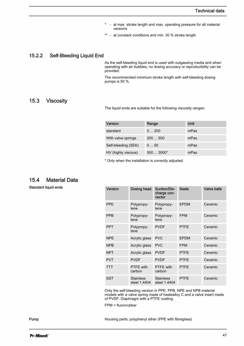
15.3 ViscosityThe liquid ends are suitable for the following viscosity ranges:
Version Range Unit
standard 0 ... 200 mPas
With valve springs 200 ... 500 mPas
Self-bleeding (SEK) 0 ... 50 mPas
HV (highly viscous) 500 ... 3000* mPas
* Only when the installation is correctly adjusted
15.4 Material DataVersion Dosing head Suction/Dis‐
charge con‐nector
Seals Valve balls
PPE Polypropy‐lene
Polypropy‐lene
EPDM Ceramic
PPB Polypropy‐lene
Polypropy‐lene
FPM Ceramic
PPT Polypropy‐lene
PVDF PTFE Ceramic
NPE Acrylic glass PVC EPDM Ceramic
NPB Acrylic glass PVC FPM Ceramic
NPT Acrylic glass PVDF PTFE Ceramic
PVT PVDF PVDF PTFE Ceramic
TTT PTFE withcarbon
PTFE withcarbon
PTFE Ceramic
SST Stainlesssteel 1.4404
Stainlesssteel 1.4404
PTFE Ceramic
Only the self-bleeding version in PPE, PPB, NPE and NPB materialmodels with a valve spring made of hastealloy C and a valve insert madeof PVDF. Diaphragm with a PTFE coating.
FPM = fluororubber
Housing parts: polyphenyl ether (PPE with fibreglass)
Standard liquid ends
Pump
Technical data
47

15.5 Electrical dataData Value Unit
Nominal power, approx. 6.4 ... 16.5 W
Current I eff 0.65 ... 0.1 A
Peak current 4.2 ...1.3 A
Switch on peak current, (within approx.50 ms falling)
15 A
Fuse* 0.8 AT
Data Value Unit
Nominal power, approx. 20 ... 25 W
Current I eff 0.9 ... 0.3 A
Peak current 5.9 ... 2.3 A
Switch on peak current, (within approx.50 ms falling)
15 A
Fuse* 0.8 AT
* Fuses must have VDE, UL and CSA certification. E.G. type 19195 manu‐factured by Wickmann in compliance with IEC Publ. 127 - 2/3.
Type Perform‐ance
Type Perform‐ance
Type Perform‐ance
W W W
1000 7.6 1602 12.2 0408 12.7
0700 6.4 1002 10.6 0413 16.5
0400 5.7 0702 9.3 0220 16.5
2001 10.5 0402 7.9 2504 21.2
1601 10.0 1604 16.5 1008 20.3
1001 8.3 1004 12.7 0713 21.2
0701 7.5 0704 11.1 0420 21.2
0401 6.9 0404 9.5 0232 24.9
2002 13.5 0708 16.5
15.6 TemperaturesData Value Unit
Storage and transport temperature -20 ... +60 °C
Ambient temperature in operation (driveand control):
-10 ... +45 °C
Version: 100 - 230 V ±10 %, 50/60 Hz,Beta®/ 4b
Version: 100 - 230 V ±10 %, 50/60 Hz,Beta®/ 5b
Power consumption
Pump, compl.
Technical data
48

Data Value Unit
Liquid end temperature -10 ... +45 °C
* long term at max. operating pressure, dependent on ambient and feedchemical temperatures
Material version Value Unit
PPT 100 °C
NPT 60 °C
PVT 120 °C
TTT 120 °C
SST 120 °C
* Temp. max., for 15 min at max. 2 bar, dependent on the ambient andfeed chemical temperatures
15.7 ClimateData Value Unit
Maximum air humidity *: 95 % rel.humidity
* non-condensing
Exposure in a humid and alternating climate:
FW 24 according to DIN 50016
15.8 Protection class and Safety RequirementsProtection against contact and humidity:
IP 65 in accordance with IEC 529, EN 60529, DIN VDE 0470 Part 1
Degree of protection:
1 - mains power connection with protective earth conductor
15.9 CompatibilitySome hydraulic parts of the Beta ® b are identical to those of the Beta ® a,gamma/ L and delta ® .
There is most compatibility with pumps of the Beta ® a, gamma/ L anddelta ® series with the following components and accessories:
n Signal cable gamma/Vario 2-, 4- and 5-wire for the "Extern" functionn Level switch 2-stage (gamma / Vario / Beta ® )n Dosing line cross-sectionsn Standard gamma connector kitn Chemical feed containern Overall height (distance between the suction and discharge con‐
nector)n Same use of accessories, such as back pressure valves, multifunc‐
tional valves, dosing monitor and flushing equipment
Liquid end, long-term*
Liquid end, short-term*
Degree of protection
Safety requirements
Technical data
49
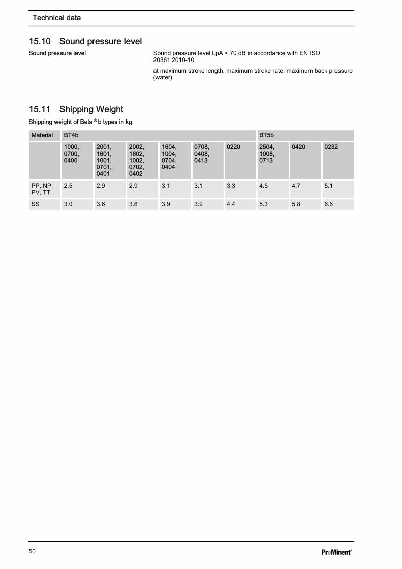
15.10 Sound pressure levelSound pressure level LpA < 70 dB in accordance with EN ISO20361:2010-10
at maximum stroke length, maximum stroke rate, maximum back pressure(water)
15.11 Shipping Weight
Material BT4b BT5b
1000,0700,0400
2001,1601,1001,0701,0401
2002,1602,1002,0702,0402
1604,1004,0704,0404
0708,0408,0413
0220 2504,1008,0713
0420 0232
PP, NP,PV, TT
2.5 2.9 2.9 3.1 3.1 3.3 4.5 4.7 5.1
SS 3.0 3.6 3.6 3.9 3.9 4.4 5.3 5.8 6.6
Sound pressure level
Shipping weight of Beta ® b types in kg
Technical data
50

16 Declaration of Conformity
- Original -
We, hereby declare that, ProMinent Dosiertechnik GmbHIm Schuhmachergewann 5 - 11DE - 69123 Heidelberg
the product specified in the following complies with the relevant basic health and safety rules of theEC Directive, on the basis of its functional concept and design and in the version marketed by us.This declaration loses its validity in the event of a modification to the product not agreed with us.
Description of the product: Metering pump, product range Beta/4 and Beta/5
Product type: BT4b .... , BT5b ....
EC Declaration of Conformity for Machinery
Serial no.: Please refer to type plate on the device
Relevant EC Machinery Directive (2006/42/EC)EC Directives: EC EMC Directive (2004/108/EC)
Compliance with the protection targets of the Low VoltageDirective (2006/95/EC) according to Appendix I, No. 1.5.1 ofthe Machinery Directive 2006/42/EC is maintained.
Harmonised standards applied, in EN ISO 12100, EN 809, particular: EN 60335-1, EN 61010-1, EN 60529, EN 55014-1, EN 55014-2,
EN 61000-3-2/3, EN 61000-4-2/3/4/5/6/8/11, EN 61000-6-3
Technical documents have been Norbert Bergercompiled by documentation Im Schuhmachergewann 5-11specialists: DE-69123 Heidelberg
Date / manufacturer's signature: 13.07.2011
Details of the signatory: Joachim Schall, Head of Development
Declaration of Conformity
51
17 Index""External Control" Terminal................... 16, 17, 28, 32, 33"Level Switch" Terminal.......................................... 16, 17AAbout this Pump.............................................................. 8Accuracy....................................................................... 46Antikink device.............................................................. 26Assembly....................................................................... 20Auxiliary Frequency..................................... 17, 19, 28, 29Auxiliary rate................................................................. 33BBackplate...................................................................... 15Bleeding.................................................................. 24, 25Bleed valve.............................................................. 15, 26Bypass tube nozzle....................................................... 15CCapacity.................................................................. 18, 32Cleaning valves............................................................. 36Compatibility.................................................................. 49Connector size.............................................................. 45Contacter relay.............................................................. 28Contacts........................................................................ 33Control Elements........................................................... 16Control type................................................................... 41Correct and proper use................................................... 9DDeclaration of Conformity.............................................. 51Decommissioning.......................................................... 43Degree of protection...................................................... 49Discharge valve....................................................... 15, 26Disposal........................................................................ 44Dosing head.................................................................. 15EElectrical data................................................................ 48Electrical Installation..................................................... 27Emergency.................................................................... 12Emptying the liquid end................................................. 43Explanation of the safety information ............................. 9External frequency changeover.............................. 17, 19Extern Contact................................ 16, 17, 19, 28, 29, 33FFault.............................................................................. 19Fault alerts.................................................................... 41Fault indicating and pacing relay option........................ 19Fault indicating relay......................................... 19, 30, 31Fault indicator (red)................................................. 16, 17Fault Statuses............................................................... 19Functions..................................................... 16, 17, 19, 32HHierarchy of Operating Modes...................................... 19
IIdentity code.................................................................... 6Inductive consumers..................................................... 28Information in the event of an emergency..................... 12Installation, electrical..................................................... 27Installation, hydraulic..................................................... 21Install hose lines............................................................ 22IP................................................................................... 49LLeakage hole................................................................. 34Level.............................................................................. 30Level switch....................................................... 17, 29, 33MMains............................................................................. 32Mains Cable.................................................................. 28Maintenance.................................................................. 34Manual.............................................................. 16, 18, 19Manual operation.......................................................... 32Material Data................................................................. 47Metering pumps with bleed valve.................................. 24Metering pumps without self-bleeding........................... 22Metering pumps with self-bleeding................................ 25Minimum Stroke Length................................................ 46Multifunctional Switch........................................ 16, 18, 32OOperating indicator (green)..................................... 16, 17Operating Modes......................................... 16, 17, 18, 19Operation...................................................................... 32Overview of the Device................................................. 15PPacing relay.................................................................. 31Parallel connection........................................................ 28Pause.................................................... 17, 19, 28, 29, 32Performance data.......................................................... 45Power consumption....................................................... 48Priming.................................................................... 19, 32Priming function............................................................ 16Priming pressure........................................................... 25Protection against contact and humidity....................... 49Protection class............................................................. 49Pulse Control Switch............................................... 16, 33QQualification of personnel.............................................. 12RRadioactive................................................................... 13RC member................................................................... 28Relay....................................................................... 19, 30Relay connection........................................................... 16Remote operation.................................................... 32, 33Repairs.......................................................................... 36Replacing the Diaphragm.............................................. 38
Index
52

Replacing the metering diaphragm............................... 38Reproducibility................................................... 18, 32, 46Return line......................................................... 22, 24, 25SSafety chapter................................................................. 9Safety declaration form................................................. 13Safety requirements...................................................... 49Scope of supply............................................................. 14SEK............................................................................... 25SEK types..................................................................... 18Self-Bleeding................................................................. 18Semiconductor switch................................................... 31Shipping Weight............................................................ 50Sleeve........................................................................... 26Sound pressure level.............................................. 12, 50Stop......................................................................... 19, 32Storage.......................................................................... 13stroke length............................................................ 18, 32Stroke Length Adjustment Knob................................... 16
Stroke rate......................................................... 16, 18, 32Strokes.......................................................................... 33Suction valve................................................................. 15Supply Voltage.............................................................. 28TTechnical data............................................................... 45Test (function)................................................... 16, 19, 32Transport....................................................................... 13Troubleshooting............................................................ 41UUnpacking..................................................................... 13VVaristor.......................................................................... 28Viscosity........................................................................ 47WWarning alert........................................................... 30, 42Warning indicator (yellow)....................................... 16, 17Warning sign................................................................... 9
Index
53