Embed Size (px)
Citation preview

1-2017
translation
OPERATING INSTRUCTIONS
PALAX C700 COMBI
powered by tractor powered by electricity powered by combustion engine swinging conveyor of 4.3-metres with hydraulic motor
SERIAL NUMBER _______________________ YEAR OF MANUFACTURE _______________________ PALAX LAHDENTIE 9 FI-61400 YLISTARO, FINLAND TEL. +358 6 4745100 WWW.PALAX.FI

1-2017 II
translation
CONTENTS 1 Basic specifications and responsibilities ................................................................... 1
1.1 Foreword ........................................................................................................... 1 1.2 EU Declaration of Conformity .......................................................................... 2 1.3 Intended use of the machine .............................................................................. 3 1.4 Warning signs ................................................................................................... 3 1.5 Type markings ................................................................................................... 4 1.6 The main dimensions and models of the machine ............................................. 5 1.7 Safety instructions ............................................................................................. 5 1.8 Noise emission and vibration ............................................................................ 6 1.9 Responsibilities of the operator ........................................................................ 6 1.10 Operating conditions ......................................................................................... 7 1.11 Terms of warranty ............................................................................................. 7 1.12 Operating instructions for the combustion engine and the winch .................... 8
2 Taking delivery and assembly of the machine .......................................................... 9 2.1 State of delivery and acceptance control .......................................................... 9 2.2 Main parts of the machine ................................................................................ 9 2.3 Installation of the adjustment lever for the splitting wedge (Fig. 2) ................. 9 2.4 Assembly of the log-stop, Figure 3 .................................................................. 10 2.5 Topping up hydraulic oil ................................................................................. 10 2.6 Bringing the conveyor into the work position, Figures 4 and 5 ...................... 10 2.7 Bringing the conveyor into the transport position .......................................... 11 2.8 Lifting and transferring the machine, Figures 6A and 6B .............................. 12
3 DRIVING POWER ................................................................................................. 13 3.1 Powered by a tractor ....................................................................................... 13 3.2 Revolutions range of the PTO-shaft ................................................................ 13 3.3 Stop switch of the tractor-powered machine (Figure 7) ................................. 13 3.4 Automatic tightening of the V-belts (Figure 8) ............................................... 14 3.5 Required measures in an emergency situation................................................ 14
3.6 Selecting the operating mode: powered by tractor or electricity (Figures 9 and 10) 14 3.7 Electric drive, start and emergency stop ........................................................ 15 3.8 Starting 15 3.9 Emergency stop of an electric-motor-powered machine ................................ 15 3.10 Starting the electric motor in frost .................................................................. 15 3.11 Honda petrol engine, start, stop and emergency stop ..................................... 16
4 Use of the firewood processor, crosscut operation ................................................. 17 4.1 Preparations before the use of the machine, all models ................................. 17 4.2 Operating the crosscut saw, before the operation .......................................... 17 4.3 During the operation ....................................................................................... 17 4.4 Placing the wood on the deck.......................................................................... 18 4.5 Crosscut operation .......................................................................................... 18

1-2017 III
translation
4.6 Disturbances during crosscut operation and their remedy............................. 18 5 Use of the firewood processor, splitting operation ................................................. 19
5.1 Splitting cylinder ............................................................................................. 19 5.2 An automatic high-speed valve is available as an option ............................... 19 5.3 Splitting wedges .............................................................................................. 19 5.4 Manual adjustment of the splitting wedge, Figure 15 .................................... 20 5.5 Hydraulic height adjustment of the splitting wedge Fig. 16, optional ........... 20 5.6 Adjusting the speed of the splitting wedge adjustment cylinder, Figure 17 .... 20 5.7 Disturbances during the splitting operation and their remedy ....................... 20 5.8 Re-splitting the logs safely .............................................................................. 21 5.9 How the safety devices affect the operation of the machine, Figure 18 ......... 21
6 Operation of the splitting mechanism ..................................................................... 22 6.1 Solitting sensor, Fig. 19 .................................................................................. 22 6.2 Parts of the launch device (Figure 20) ........................................................... 22 6.3 Operational principle of launching ................................................................. 22 6.4 Hand-start of the splitting motion, Figure 21 ................................................. 23 6.5 Parts of the hydraulic valve (Figure 22) ......................................................... 23 6.6 Operation of the valve ..................................................................................... 23
7 Maintenance of the machine ................................................................................... 24 7.1 Crosscut saw-blade ......................................................................................... 24
7.1.1 Removing the crosscut saw-blade (Figures 23 and 24) ..................... 24 7.1.2 Sharpening the chain .......................................................................... 24 7.1.3 Stressing the saw-blade ...................................................................... 24
7.2 Guide for crosscut saw-blade (Figure 25) ...................................................... 25 7.2.1 Adjustment of the saw-blade guide ................................................... 25
7.3 Automatic tightening of the angular gear V-belts, Fig. 26 ............................. 25 7.4 Changing the V-belts, angular gear ................................................................ 25 7.5 Changing the oil in the angular gear .............................................................. 26 7.6 Lubricating the machine, Fig 28 ..................................................................... 26 7.7 Clutch for hydraulic pump, Fig. 29 ................................................................ 27 7.8 Changing the oil .............................................................................................. 27 7.9 Maintenance of the valve ................................................................................ 27 7.10 Detent end of valve .......................................................................................... 28 7.11 Lubricating the spool shifter, Fig. 33.............................................................. 28 7.12 Structure of the detent end and the correct order of the parts, Fig. 34 .......... 28 7.13 Initial settings of the valve (Figures 35 and 36) ............................................. 29 7.14 Adjustment of launch bar clearance ............................................................... 30 7.15 Conveyor transmission, Fig. 37 ...................................................................... 30 7.16 Conveyor chains, Fig. 38 ................................................................................ 30 7.17 Cleaning the machine ...................................................................................... 30 7.18 Washing the machine ...................................................................................... 31 7.19 Storing the machine. ....................................................................................... 31

1-2017 IV
translation
8 Maintenance schedule ............................................................................................. 32 9 Malfunctions and their remedy ............................................................................... 33 10 Electric diagrams .................................................................................................... 34

1
translation
1 BASIC SPECIFICATIONS AND RESPONSIBILITIES
1.1 Foreword
This Instruction Manual is intended for a professional operator of the machine. The operator must have usual general knowledge and skills. For example, the buyer of a tractor-powered machine is expected to master the use of power take-off shaft transmission. Before the installation and operation, the operator of the machine must become thoroughly familiar with the contents of the manual. The operator is also obliged to gain familiarity with the operating controls of the machine and the emergency stop mechanism. For more information about our products, please visit our website at www.palax.fi. NOTE! Keep this manual with the machine at all times.

2
translation
1.2 EU Declaration of Conformity
Directive 2006/42/EC Manufacturer: Ylistaron Terästakomo Oy www.palax.fi
Lahdentie 9 FI-61400 Ylistaro Finland +358 6 474 5100
The person in charge of Technical Construction File: Kai Koskela,[email protected] Product: PALAX C700 Combi
a firewood processor with 4,3-m discharge conveyor Powered by: tractor PTO, electric motor or combustion engine Models: TR Powered by tractor equipped with own hydraulic
system TR/SM Powered by tractor / electric motor PM Combustion engine Serial number of the machine: We hereby certify that the machine meets the requirements of the Government Decree 12.6.2008/400 on safety of machinery through which the Machine Directive 2006/42/EC has been put into effect, and that during the manufacturing process the following harmonized standards have been applied.
SFS-HANDBOOK 93-series, SFS-EN 349-1+A1, SFS-EN 609-1+A1, SFS-EN 618, SFS-EN 847-1+A1, SFS-EN 847-2+A1, SFS-EN 847-3, SFS-EN 953+A1, SFS-EN 954-1, SFS-EN 982+A1, SFS-EN 1870-6, SFS-EN 4254-1, SFS-EN 11684, SFS-EN 12100-1+A1, SFS-EN 12100-2, SFS-EN 13850, SFS-EN 13857, SFS-EN 14121-1, ISO/TR 14121-2, SFS-EN 60204-1+A1.
Notified body No.0504:
Luonnonvarakeskus ( Luke ) Mittaus ja standardisointi ( Vakola ) Vakolantie 55 03400 VIHTI Ylistaron Terästakomo Oy 10.2.2016
Pekka Himanka Managing Director

3
translation
1.3 Intended use of the machine
This Firewood Processor with Conveyor is intended for the purpose of producing firewood primarily of round timber, but of logs as well. Use of the machine for any other purposes is prohibited.
Note! Max. capacity of the machine For cutting, the maximum diameter of the tree is about 25 cm. The maximum length of the log to be processed is 4 metres. If the logs are longer
than this, they must be pre-cut to at most 4 metres.
1.4 Warning signs
Beware of the crosscut saw-bar
Read the instruction manual
Lifting points
Use eye guards and hearing protectors
Wear clothes, which do not hang loosely
Wear safety shoes Use protective
gloves
Manual stop of the splittig cylinder
Direction of rotation of tthe blade
Revolutions range for PTO- shaft

4
translation
1.5 Type markings
Nameplate on the machine The name and address of the manufacturer Designation of the machine type Serial number and year of manufacture Total weight of the machine Diameter of the crosscut saw-blade 700mm Diameter of the saw-blade hole 35mm Max 2000 r.p.m. Nameplate at the rear of the crosscut saw housing Always mention the serial number and year of manufacture when ordering spare
parts. Nameplates on the electric drive 3-phase motor Voltage 380 V Output 7.5 kW
Hydraulic height adjustment of the splitting wedge, optional
Manual start of the splitting cylinder
Stay away from moving partsof the machines
Beware of PTO- shaft
Disconnect the machine from the electric supply before taking to any service measures
The machine may only be operated by one person
Power switch for the oil heater
Safe distance from the conveyor
Stopping the machine by slackening the V-belts

5
translation
1.6 The main dimensions and models of the machine Item
Powered by tractor TR /operated by electricity
Powered by combustion engine
Output - 7.5 kW 13 hp
Fuse size - 16 A -
Weight 660 kg 720 kg 710 kg
Height/width/length 2400 mm x 2,830mm x 1,450mm
Crosscut deck Length 950 mm, with extension table 1,950 mm
Height of crosscut deck 800 mm
Diameter of blade/hole 700/ 35 mm
Max. rotation speed of blade 2000 r.p.m.
Max. diameter of the log 25cm
Max. length of tree, splitting 600 mm
1.7 Safety instructions
General regulations and restrictions The maximum length of the log to be cut is 4 metres. Danger of turning over! The machine is exclusively intended for the production of firewood. The machine may only be operated by one person. The machine must be equipped with appropriate lights and reflectors for
transportation on public roads. The danger zone around the conveyor is 5 metres to the sides and to the rear Always lock the crosscut deck in the rear position for transportation. Always shift and lock the table extension into its rear position for transportation. The three-point linkage of the tractor is of size-category two. If using a tractor larger
in size, check that there is sufficiently space for the PTO-shaft and its protective guard.
Never use the machine indoors – risk of dust generation. The use of a machine powered by combustion engine involves danger of exhaust gases.
Never remove any safety-related devices from the machine. The width of the machine equipped with the 4,3-m conveyor is about 2.83 m. This
means that, depending on the size of the tractor, the transport width of the conveyor may extend outside the rear wheel on the right-hand side.
The operator Every person operating the machine, must thoroughly study the entire user
manual. Always use eye guards and hearing protectors. Always wear protective shoes. Always wear work gloves. Do not wear loosely-fitting clothing. Before use Make sure that all other people stay outside the operating range. Always hitch the tractor-driven machine to the three-point linkage. Also ensure that
sufficient space is provided for the PTO-shaft and its guard.

6
translation
Release the crosscut chute from its transport position before launching the crosscut operation.
Only use a fault-free power take-off drive shaft and attach the chain for the shaft-guard. Max. 450 r.p.m.
Only operate the machine on a sufficiently firm and level surface. Only operate the machine in an adequately lit space. Keep the exhaust pipe of the combustion-engine-driven unit at a safe distance from
anything that might catch fire! Danger of fire! Always check that all the covers are intact and properly fastened. Always check that the crosscut saw-bar is intact. Always ensure that the electric conductors are intact. Always check that all the controls are operational. Always check the oil level and make sure that the hydraulic hoses and components
are free of damage. Before starting the work, make sure that the machine is firmly in position. During operation Carelessness during the cut-off operation constitutes a major hazard! During the cut-off operation, make sure that the tree is always supported at the
support rollers of the crosscut deck. Danger of rolling over! Exercise particular caution when cutting knotty or crooked logs, because, as a
result of faulty cutting, the log might roll over or twist the saw-bar with enough force to break it.
Keep the working space clean and clear of foreign objects. Always stop the engine for refuelling. Always stop the machine before servicing. Only cut one log at a time. Danger! Stay away from moving parts. Beware of the hot exhaust pipe on the combustion-engine-driven unit!
1.8 Noise emission and vibration
Equivalent continuous A-weighted sound-pressure level at the workstation is 85.4 dB (A) and the sound power level is 105.4 dB (A).
The vibration emission values do not exceed the limit 2.5m/s2.
1.9 Responsibilities of the operator
All the safety-related devices are necessary to ensure a sufficient level of safety. The machine operator is responsible for the flawless operation of the safety-related
devices and for ensuring that the machine is serviced in a due manner. Modifying the construction of the machine is prohibited. The machine must never be operated under the influence of alcohol or drugs. The machine may only be used to produce firewood. The operator is responsible for ensuring that no one else is subjected to any
danger. As the operator, remember that you are fully responsible for any injuries caused by
the removal of any safety-related devices from the machine, or by any modification to its operation.

7
translation
The C700 Combi is a very safe machine provided that it is operated carefully following the instructions and that it is serviced regularly.
1.10 Operating conditions
Always place the machine on as level a surface as possible. Prevent risks, such as slipping in winter, by organising the work sit–e in a due
manner. Only operate the machine in an adequately lit space. It is recommended that a suitable stand be purchased or made that enables the
trees to be processed where the logs are ready at the level of the in-feed deck. Hence, unnecessary lifting may be avoided and the work can proceed much faster.
The suitable temperature range for operation is approximately -20 to +30 degrees Centigrade. When starting the machine in severe frost, first allow it to idle at low speed for about 5 to 10 minutes. This way, the oil warms up and flows better, so risk of damage to the seals is reduced.
No restrictions concerning the weather apply. Make sure that no other people, especially children, are present inside the
operating range. Never use the machine indoors – risk of dust generation. Use of the combustion
engine-powered machine may involve danger of exhaust gases.
1.11 Terms of warranty
The warranty period runs for 12 months from the date of purchase. The warranty covers
Parts, damaged during normal operation of the machine due to defects in material or workmanship.
The reasonable repair cost in accordance with the agreement between the seller and the manufacturer or the buyer and the manufacturer.
A new part delivered as a replacement for the defective one. The warranty does not cover
Defects due to normal wear, faulty operation or negligent maintenance. The crosscut saw-blade, V-belts or oil. Defects in the machine due to any modifications which the buyer has made or
ordered from a third party and which have affected the machine in such a way that it can no longer be considered to correspond to its original configuration.
Other possible expenses or financial demands due to the above-mentioned measures.
Any indirect costs and/or travel expenses incurred from making repairs under the guarantee.
The combustion engine, whose obligations under warranty lie with the manufacturer of the engine.
For parts changed during the warranty period, the warranty expires at the same time as the warranty period of the machine.
Consult your dealer about matters related to the warranty.

8
translation
1.12 Operating instructions for the combustion engine and the winch
Refer to the manuals on our website at www.palax.fi for detailed operating and servicing instructions for the combustion engine and the winch. In matters related to the combustion engine turn to the nearest Honda dealer.

9
translation
2 TAKING DELIVERY AND ASSEMBLY OF THE MACHINE
2.1 State of delivery and acceptance control
The machine is delivered almost ready-assembled and test driven. In order to prevent transport damage, the adjustment lever for splitting wedge 12,
the operating lever for log-stop 10 and the protective net for crosscut saw-blade 9 have been removed and packed separately. (Fig. 1)
Check the delivered goods without delay. If the product shows transport damage, contact the transport company and your
dealer immediately.
2.2 Main parts of the machine
1. Table extension 2. Oil tank 3. Emergency stop lock 4. Emergency stop 5. Manual start of the splitting
cylinder 6. Disengaging clutch of the
angular gear 7. Crosscut deck 8. Saw-blade cover 9. Protective net for saw-
blade 10. Log-stop control lever 11. Protective net for splitting
chute 12. Adjustment lever 12 for the
splitting wedge 13. Conveyor
1
1 2 3 4 5 6 7 8 9 10 11 12 13 Fig. 1. Main parts of the machine
Install protective net 9 as shown in Fig. 1 so that its front edges and the front edges of the protective net for splitting chute 11 come into line.
2.3 Installation of the adjustment lever for the splitting wedge (Fig. 2)
Remove the splint, nut and cup springs. Position the adjustment lever so that the friction plate A comes between the frame
bar and the lever. Put the adjusting lever in place. Install the cup springs as instructed by the sticker.

10
translation
Put the crown nut in place, adjust the lever to a suitable tightness and put the splint in place.
NOTE! Do nut lubricate the friction plate A!
2.4 Assembly of the log-stop, Figure 3
1. Unscrew the attachment nut A for the log-stop. 2. Push the shaft B into the hole in the table and place the log-stop A on the shaft
B. 3. Push the shaft in place and fix the cotter. 4. Put the spring C in place. 5. Adjust the log-stop A as follows:
A. When the table is in the rear posistion, the log-stop is in the limiting position. B. When the deck is pushed forward, the log-stop folds completely away from the log.
2.5 Topping up hydraulic oil
Hydraulic oil volume 40 litres. Oil type Univis 32, SHELL Tellus 32, NESTE HYDRAULI 32 or equivalent. Only use fresh, clean oil. Observe particular cleanliness during the oil change, because smooth operation of
the machine is highly dependent on the purity of the oil.
2.6 Bringing the conveyor into the work position, Figures 4 and 5
1. Release the locks for the conveyor. 2. Uncoil the wire of the winch about twelve rounds. 3. Pull out the conveyor and leave it supported by the winch rope. 4. Lower the conveyor to the ground using the winch.
2
A B C
3
A
C B
Fig. 2. Installing the adjustment lever
for the splitting wedge, Fig. 3. Installing the log-stop,

11
translation
5. Pull open lock A (Fig. 4). 6. Swing down the top of the conveyor. 7. Remove the support bar B for the conveyor chain (Fig. 5) and attach it to the
holes C at the edge of the conveyor. 8. Put the attachment chain and the splints back in place.
4
A
5
B
A C
Fig. 5. Unfolding the conveyor 2/2
Fig. 4. Unfolding the comveyor 1/2
2.7 Bringing the conveyor into the transport position
1. Disconnect the attachment chain for the conveyor. 2. Lower the conveyor to the ground and connect the support bar B for the
conveyor chain, Fig. 5. 3. Pull lock A open and lift up the conveyor top. 4. Ensure that lock A is properly locked. 5. Raise the conveyor using the winch. 6. Tighten the winch wire lightly in order to prevent it uncoiling from the spool. 7. Lock the conveyor in the transport position.
NOTE! Always hold by the winch handle as you lower the conveyor.

12
translation
2.8 Lifting and transferring the machine, Figures 6A and 6B
Lifting the machine is allowed: Using the forks of a forklift truck
placed under the frame beams of the machine in the front or rear, observing the centre of gravity of the machine..
By lifting points A at the upper part of the machine. Fig. 6A.
NOTE! The machine must be equipped with appropriate lights and reflectors for transportation on public roads. Fig. 6B
9A A
Fig. 6A. Lifting points of the machine
6B
Fig. 6B. Example of additional lighting

13
translation
3 DRIVING POWER
The Palax C700 Combi firewood processor may be driven by a tractor, an electric motor or a combustion engine.
3.1 Powered by a tractor
Always connect the machine to the tractor’s three-point linkage and ensure that the space reserved for the PTO-shaft and its guard is sufficient.
A suitable size for power take-off drive shaft is, for example, a BONDIOLI 143 or WALTERSCHEID W 2100.
No safety clutch is required for the PTO-shaft. Only use fault-free PTO-shafts and always attach the chains for the shaft-guard to
the machine. NOTE! When you disconnect the PTO-shaft from the tractor, hang it in the hook on the machine. The machine comes with towing pins of 28 mm. If the power take-off of the tractor has a high-speed range, then it should be used,
because the horsepower requirement of the circular saw is small. Make sure that the speed of the power take-off shaft does not exceed 450 r.p.m.
3.2 Revolutions range of the PTO-shaft
The suitable revolutions range is 400-450 r.p.m.
3.3 Stop switch of the tractor-powered machine (Figure 7)
The tractor-powered machine is equipped with a special emergency stop device to immediately disengage the transmission between the angular gear and the saw-blade shaft.
In case of emergency, pull the lever A. When lever A is pulled, tightening wheel B
swings down and the V-belts slacken (Figure 8). Disengagement lever A locks up and the belts remain slack.
7 A
Fig. 7. Stop switch of the TR model

14
translation
3.4 Automatic tightening of the V-belts (Figure 8)
As the switch is released, the tightening wheel, affected by spring C, presses the V-belts on the slack side and the V-belts of the angular gear and the blade shaft automatically remain at correct tightness.
8
B
C
Fig. 8. Tightening the V-belts
3.5 Required measures in an emergency situation
If the clutch has been used in an emergency situation, e.g. when a log has stuck in the circular saw-blade as a result of a mistake during the sawing, then immediately disconnect the power take-off transmission of the tractor as well, because the pulley of the angular gear can wear down the V-belts unnecessarily. NOTE! When the clutch is reset to the operating position, the power take-off drive shaft must be disconnected from the tractor. Only use the clutch in an emergency situation!
3.6 Selecting the operating mode: powered by tractor or electricity (Figures 9 and 10)
The machine is equipped with a system to prevent simultaneous operation in two modes.
When the cover plate is shifted to the left (Figure 9), it is possible to connect the extension cable, and when it is shifted to the right (Figure 10), it is possible to connect the power take-off shaft.
9
A
Fig. 9. Selecting the powered-by-electricity mode
10
A
Fig. 10. Selecting the powered-by-tractor mode

15
translation
3.7 Electric drive, start and emergency stop
The power output of the motor is 7,5 kW at a speed of 1450 r.p.m. The machine is equipped with an automatic Y-D starter with an emergency stop
feature. All electric installations must be completed. In the 380 V-system the fuse size is 16 A slow. The cross-section of the required extension cord is 2,5 mm2. Before starting up the machine, check that it rotates in the direction shown by the
arrow at the end of the motor. Check the direction of rotation by allowing the motor to run for a short while and,
after that, stopping it immediately. NOTE! Only skilful professionals are allowed to carry out the electric work that changing the direction of rotation requires. Make sure that the extension cord, that you use, is equipped with a switch that enables changing the direction of rotation of the motor using a screwdriver.
3.8 Starting
Press the start button. In the Y-position the motor starts rotating at slow speed with low output. The start phase takes several tens of seconds.
As the engine speed increases, the D-position is switched on and the motor quickly reaches full speed. As the position D is switched on, the signal light between the start and stop switches illuminates.
NOTE! The machine must not be operated until the motor has reached full speed, because in the Y-position the output of the electric motor is very low.
3.9 Emergency stop of an electric-motor-powered machine
The emergency stop is carried out by depressing the Emergency Stop button, button B on the starter.
The button is reset by pulling it up.
3.10 Starting the electric motor in frost
In severe frost, the hydraulic oil and the oil in the angular gear can become so cold and viscous or the V-belts so rigid that the motor cannot be started.
If operating the machine under cold conditions, we recommend that less viscous hydraulic oils be used.
NOTE! A 300 W electric heater carpet with thermostat is available as an option for the hydraulic oil tank. We recommend using the carpet whenever the machine is operated under cold conditions. The starter is equipped as standard with a lever switch for the heater. Keeping the heating switched on for about 1-2 hours is enough to make the oil sufficiently fluent.

16
translation
3.11 Honda petrol engine, start, stop and emergency stop
Refer to the engine’s instruction manual for detailed operating and servicing instructions.
Check the oil level in the engine and top it up if necessary. NOTE: petrol is highly flammable! Use 95E petrol in the combustion engine. Always stop the machine for refuelling. Take care not to spill petrol on the hot engine. Starting the motor Fig. 12
1. Check that the engine V-belts have been slackened using the clutch.
2. Shift the gas lever to about half-way, activate the choke and pull the starter grip.
3. As soon as the motor starts, reduce the setting of the choke gradually to make the engine run smoothly.
4. Switch on the V-belt drive by shifting the clutch lever B and increasing the engine revolutions to maximum.
5. The pre-set engine revolutions are equal to about 2000 revolutions on the saw-blade shaft.
12 Fig. 12. Clutch lever for V-belts in a combustion-engine-powered machine
Stopping
1. Shift the gas lever to idling. 2. Turn off the engine with the switch. 3. Close the fuel valve.
The V-belts must be kept tight during transportation, to prevent the engine from “jumping”.
Emergency stop Turn off the engine with the switch.

17
translation
4 USE OF THE FIREWOOD PROCESSOR, CROSSCUT OPERATION
4.1 Preparations before the use of the machine, all models Position the conveyor as instructed in point 2.6. Re-attach the lock chain in the slot. Open the locking of the table extension and pull out the table. Lock the extension
table in position. NOTE! If the length of the log you intend to cut is, for example, 3 metres, then the extension table may be almost in its inner position provided that the log to be processed is placed on the table with its root-end first. Doing so makes the feeding process easier, as the log stays on the rollers the maximum amount of time.
4.2 Operating the crosscut saw, before the operation
Cleanse the new circular saw-blade of any protective grease, because a greasy blade accumulates resin easily, making it heat up, lose its tension and start to wobble.
4.3 During the operation
Exercise caution, always keep your hands away from the saw-blade. Never stop the rotation of the blade by pressing wood against its side or its teeth. During the crosscut operation, make sure that the log is always supported on the
roller at the cutting point. If a hard-metal blade is used, a particular setting is not necessary, as the hard-
metal blade is always slightly thicker than the blade-disk itself.
18
translation
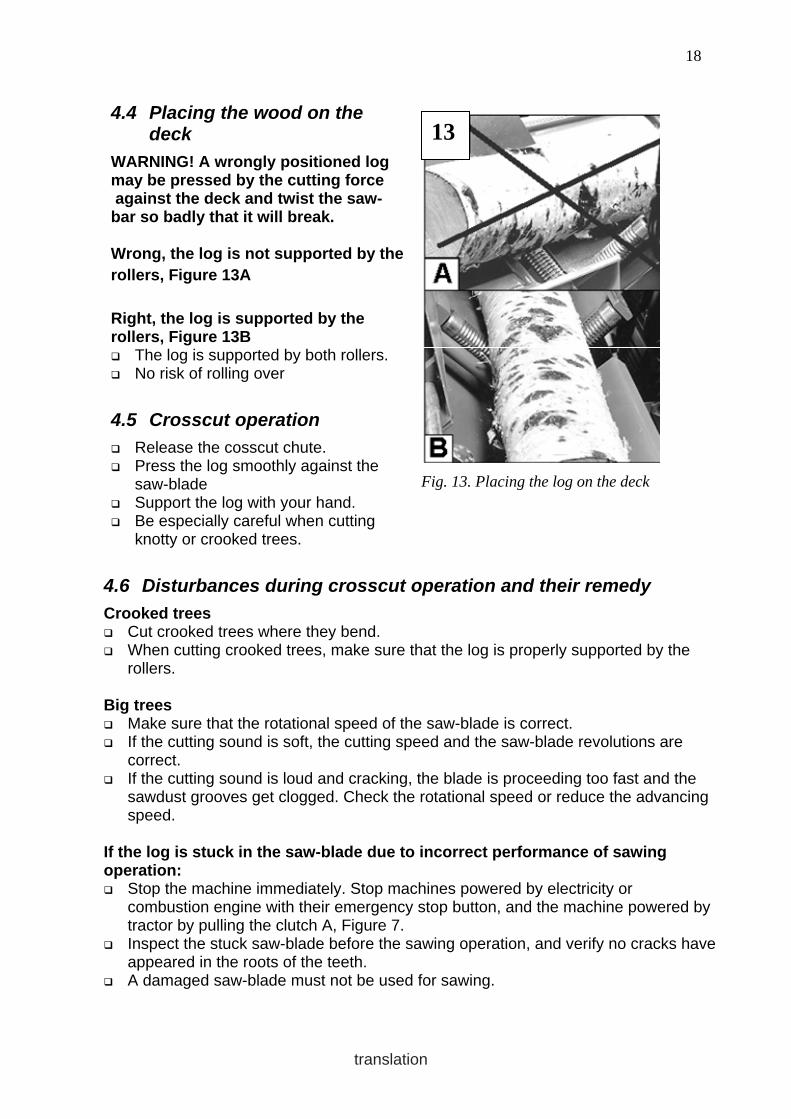
4.4 Placing the wood on the deck
WARNING! A wrongly positioned log may be pressed by the cutting force against the deck and twist the saw-bar so badly that it will break. Wrong, the log is not supported by the rollers, Figure 13A Right, the log is supported by the rollers, Figure 13B The log is supported by both rollers. No risk of rolling over
4.5 Crosscut operation
Release the cosscut chute. Press the log smoothly against the
saw-blade Support the log with your hand. Be especially careful when cutting
knotty or crooked trees.
13
Fig. 13. Placing the log on the deck
4.6 Disturbances during crosscut operation and their remedy
Crooked trees Cut crooked trees where they bend. When cutting crooked trees, make sure that the log is properly supported by the
rollers. Big trees Make sure that the rotational speed of the saw-blade is correct. If the cutting sound is soft, the cutting speed and the saw-blade revolutions are
correct. If the cutting sound is loud and cracking, the blade is proceeding too fast and the
sawdust grooves get clogged. Check the rotational speed or reduce the advancing speed.
If the log is stuck in the saw-blade due to incorrect performance of sawing operation: Stop the machine immediately. Stop machines powered by electricity or
combustion engine with their emergency stop button, and the machine powered by tractor by pulling the clutch A, Figure 7.
Inspect the stuck saw-blade before the sawing operation, and verify no cracks have appeared in the roots of the teeth.
A damaged saw-blade must not be used for sawing.

19
translation
5 USE OF THE FIREWOOD PROCESSOR, SPLITTING OPERATION
5.1 Splitting cylinder The machine can be equipped with a splitting cylinder of either 3,5 tons or 5,6 tons.
5.2 An automatic high-speed valve is available as an option
An automatic high-speed valve, with splitting motion normally at high-speed, is available as an option.
The speed decreases only for a short while as the required splitting force increases when thick logs are being processed. As the log starts to split, the force requirement immediately drops and the splitting motion resumes the high-speed operation.
The automatic high-speed valve speeds up processing of the firewood considerably and at the same time reduces the load on the transmission.
The automatic valve is also available for retro-fitting.
13 14
Fig. 14.Automatic high-speed valve
5.3 Splitting wedges
Short, straight wedge, optional The short straight wedge for splitting the wood in 2 ways or, if the wedge is lowered
down, no splitting at all. In 2/4 ways, standard The standard wedge for splitting in two or four ways. In 2/6 ways, option A wedge for splitting the log in two or six ways Normally requires a cylinder of 5,6 tons.

20
translation
5.4 Manual adjustment of the splitting wedge, Figure 15
The machine is equipped with a manual system for height-adjustment of the wedge.
The lever with friction plate A for stepless adjustment keeps the wedge at the correct height at all times.
The stiffness of the lever movement can be adjusted by tightening the cup springs B of the friction plate.
Note! Never use grease on the friction plate.
5.5 Hydraulic height adjustment of the splitting wedge Fig. 16, optional
The splitting wedge may also be adjusted hydraulically by means of the lever on the crosscut deck.
For hydraulic adjustment a small side flow is diverted from the main oil flow by means of a flow regulation valve.
5.6 Adjusting the speed of the splitting wedge adjustment cylinder, Figure 17
A = Flow regulation valve Adjustment The speed of the adjustment cylinder is
increased by turning the valve A to the left. NOTE! Use as small a flow as possible as the diverted oil flow is lacking from the flow to the splitting cylinder.
A
14
B
15
Fig. 15. Manual adjustment of the splitting wedge
15
16
Fig. 16. Hydraulic adjustment of the splitting wedge
16
A
17
Fig. 17. Flow regulation of the adjustment cylinder
5.7 Disturbances during the splitting operation and their remedy
A stuck log: When the logs are big and have big branches, the force of the in-feed cylinder may
fall short. If the tree sticks to the wedge, reverse the cylinder using the pedal. Raise the splitting-wedge and retry the splitting using the manual control. Changing
the position of the log often helps.

21
translation
If the log does not split, depress the splitting cylinder emergency stopper pedal to reverse the cylinder and lock up the control valve. This makes it safe to remove the log.
Open the protective net and hit the stuck wood loose using another piece of wood. If the log has a big branch, make the branch split by turning the log and pushing it
towards the wedge with the root end first. Doing it this way requires the least power..
5.8 Re-splitting the logs safely
If you want to produce small-size firewood from large logs, even wood split by the 4 or 6-way wedge may still be too large in size.
Proceeding in the following way will help you to split the wood safely into even smaller pieces. 1. Open the protective net for splitting chute 2. Place the logs to be split into the splitting chute. 3. Close the protective net. 4. Start the splitting operation with the manually-operated start lever.
5.9 How the safety devices affect the operation of the machine, Figure 18
Stopping the splitting cylinder The machine does not operate unless the lock-up device A for the splitting cylinder
stopper is in the open-position and the pedal B is not in the upper position. Disengagement switch for the angular gear Keeping the V-belts tight and the machine operational requires that disengagement
switch C for the transmission be pushed towards the tractor. NOTE! Machines powered by combustion engine are not equipped with clutch and angular gear Protective net for splitting chute The splitting motion does not
operate unless protective net D of the splitting chute is in the closed position.
If the protective net is lifted by about 30 mm, the splitting motion will stop and the cylinder will reverse to its initial position.
Warning ! All the safety-related devices are
necessary to ensure a sufficient level of safety.
Do not remove any of the safety features from the machine. The machine operator is responsible for the flawless operation of the safety-related devices.
18
A B C D
Fig. 18. Safety-related devices, which affect the operation

22
translation
6 OPERATION OF THE SPLITTING MECHANISM
6.1 Solitting sensor, Fig. 19
The splitting sensor is placed in the splitting chute so that the falling log always hits it straight on.
Small logs are also capable of starting the splitting motion.
23
Fig. 19. Splitting sensor
1 2 3 4 5 6 7 8
9
20
Fig. 20. Parts of the launching device
6.2 Parts of the launch device (Figure 20)
1. Lock bar 2 Support bearing 3 Guide bearing 4 Safety wedge 5 Sensor 6 Adjustment sleeve 7 Launch bar 8 Limiter bearing 9 Control lever for manual start 10 Stroke limiter
6.3 Operational principle of launching
1. As the wood falls into the splitting chute, it hits the tip of the sensor (Figure 18). 2. Sensor rod 5 (Figure 20) lifts up launch rod 7 by means of the adjustment
sleeve, which is released from behind fixed limiter bearing 8. 3. The launch rod 7 starts the splitting motion by means of the spring force.

23
translation
6.4 Hand-start of the splitting motion, Figure 21
The splitting motion can also be started with the hand-start lever by pushing the lever in the direction of the arrow.
The manually operated launch lever affects the control lever 9 for manual start (Fig. 20), which depresses the bevel surface of the launch rod 7. This makes the launch rod rise from behind the limiter bearing 8, starting the splitting operation.
21
Fig. 21. Manual starter for the splitting operation
6.5 Parts of the hydraulic valve (Figure 22)
1 Tightener 2 Launch spring 3 Adjustment part of launch
spring 4 Launch bar 5 Control lever 6 Locking lever of net cage 7 Detent end of valve 8 Valve 9 Spool shifter 10 Shaft 11 Launch bar 12 Locking lever for pedal 13 Locking lever spring
1 2 3 4 5 6
10 11 12 13
7 8 9
22
Fig. 22. Parts of the hydraulic valve
6.6 Operation of the valve
Tightener, part 1 Stops and reverses the splitting cylinder, stops the valve in free-circulation and
tightens the launching spring 2 for a new movement. Locking lever, part 6 Lifting up the protective net for the splitting chute shifts the locking rod 1 (Figure
20) by means of the safety wedge 4 into a position where the locking lever 6 (Figure 22) impedes the movement of the launch rod 4.

24
translation
7 MAINTENANCE OF THE MACHINE
Note! Always stop the machine before servicing.
7.1 Crosscut saw-blade
7.1.1 Removing the crosscut saw-blade (Figures 23 and 24)
1. Loosen the side plate of the sawdust trough A (a 17 mm spanner). 2. Remove the side plate of the saw-blade cover (13 mm spanner) and the blade
cover (17 mm spanner). 3. Put pin A into hole B indicated by the arrow (Figure 24) to prevent the saw-
blade from rotating and twist open the saw-blade nut (right-handed thread, 36 mm spanner). The thread on the nut is M 24 x 2.
4. Carefully clean the surfaces of the flanges before re-installation of the blade. 5. Before installing the blade, make sure that the pin, which prevents the saw-
blade from rotating, is in place.
23 A
B
Fig. 23. Removing the crosscut saw-blade 1/2
24
B
A
Fig. 24. Removing the crosscut saw-blade 2/2
7.1.2 Sharpening the chain
The hard-metal blade can be sharpened "lightly" using a diamond file. Depending on the cleanliness of the wood, as many as 5001000 bulk cubic metres
of wood can be processed with a hard-metal saw-blade without resharpening. The best sharpening result and durability of the blade is achieved when the saw-
blade is sharpened using an appropriate grinding machine and a diamond file.
7.1.3 Stressing the saw-blade
Stressing-faults do not usually occur in hard-metal blades, but if the blade is very blunt such faults are possible. Always take such a blade to a professional saw-blade service.

25
translation
7.2 Guide for crosscut saw-blade (Figure 25)
The guide A for the crosscut saw-blade A at the side of the sawdust trough prevents the blade from coming into contact with the edge of the sawdust trough in case of malfunction.
Check the clearance between the piece of wood and the blade from time to time. Adjust as required. A suitable clearance is about 2-3 mm.
25
B A C
Fig. 25. Crosscut blade guide
7.2.1 Adjustment of the saw-blade guide
1. Loosen the bolt B. 2. Loosen the lock nut of the adjustment bolt C and adjust the clearance with the
bolt to about 2-3 mm. 3. Tighten the nuts.
7.3 Automatic tightening of the angular gear V-belts, Fig. 26
The spring B draws the tightener from the slack side of the belts. Then the belts automatically remain in correct tightness .
Belt type SPA 1382, 2 pcs
7.4 Changing the V-belts, angular gear
1. Slacken the V-belts using the emergency switch (Figure 27).
2. Remove the cover plates and the blade as instructed in point 7.1.
3. Replace the old belts with the new ones, type SPA 1382, two pcs.
4. Push the emergency switch forward. The spring then sets the belts to the correct tightness.
5. Carefully clean the surfaces of the flanges before re-installation of the blade.
6. To make the belts settle in place, allow the machine run for a few moments without any load.
26
A B
Fig. 26. V-belts
27
A
Fig. 27. Tightening and slackening of the V-belts

26
translation
7.5 Changing the oil in the angular gear
The oil plug is at the side of the angular gear. The angular gear must be demounted for the oil change, or the used oil must be
drained, for example, by means of suction drainage. Fill up with about 0,5 litres of new oil. The upper limit is at the lower edge of the filling opening. Oil type SAE 80 NOTE! The combustion-engine-powered machine lacks angular gear and related parts such as V-belts, belt-tightener or emergency switch.
7.6 Lubricating the machine, Fig 28
If the machine is left unused for a longer period of time, lubricate the shaft bearings A (Figure 28) with roller-bearing lubricant in accordance with the table at the end of the operating season.
NOTE! If the machine is left standing for a longer period of time, it is important that the bearings always be provided with clean lubricant.
A
Fig. 28. Lubricating the machine
Lubricate daily with oil the moving joints, log-stop, legs of the deck and the support rollers.

27
translation
7.7 Clutch for hydraulic pump, Fig. 29
Check the clutch rubber A at regular intervals.
For example, every time the shaft bearings are lubricated.
If the clutch clearly shows play, change the rubber.
If the clutch makes an unusual rattle, the rubber has worn out and it must be replaced immediately.
29
A
Fig. 29. Clutch for hydraulic pump
7.8 Changing the oil
To ensure flawless operation of the machine, the oil must be changed every 500 operating hours or at least one year after the start of operations.
The oil plug is located in the outer corner of the tank bottom. The filter must also be replaced because contaminants that end up in the filter
are constantly extracted from the system.
30
Fig. 30. Oil tank
31
A B
Fig. 31. Valve
7.9 Maintenance of the valve
To withstand and operate flawlessly, the detent end A, the spool shifter joint B and the ball joint of the control valve require regular lubrication.
Lubrication of the valve is particularly important if the machine is left standing for several months.
If the parts of the detent have become rusty, the machine will not operate flawlessly.

28
translation
7.10 Detent end of valve
There is a small hole in the middle of the end plate of the detent end of the valve for spraying lubricant onto the moving parts of the valve. The screw in the middle of the cover plate must be removed first. (Fig. 32)
Only use oil that does not congeal in frost. The easiest way is to use a spray bottle with a
nozzle and pipe. Insert the spray pipe in the hole and press 2-3
times for about 1-2 seconds at a time. The oil spreads smoothly on the moving parts of
the detent end. NOTE! Do not use spray Vaseline because it congeals in severe frost and the valve will not operate properly.
32
Fig. 32. Detent end of valve
7.11 Lubricating the spool shifter, Fig. 33
The spool shifter is equipped with a pin and a ball joint that require regular maintenance and lubrication. 1. Lift up the edge of the protective rubber of
the spool shifter. 2. Spray lubricant on both sides of the pin and
down on the ball joint. 3. At the same time, check that the rubber is
intact.
33
Fig. 33. Spool shifter
7.12 Structure of the detent end and the correct order of the parts, Fig. 34
Keep cover C of the detent end depressed while opening screws B, as the stiff springs can throw the cover off. This can also make the springs and balls of the detent fly off.
In connection with assembly of the detent end, apply a small amount of Vaseline to holes A of the detent. This ensures the balls stay properly in position during assembly. Make sure that parts D and E line up in the right way, as shown in the picture.
The small holes at the ends of part E are for drainage of condensed water. During assembly, make sure that the holes come on the underside.

29
translation
34 A
B C
D E F
Fig. 34. Structure of the valve’s detent end
7.13 Initial settings of the valve (Figures 35 and 36)
The valve has been adjusted and test run at the factory. The initial settings do not usually change so there is rarely any need for
readjustment. In the long run, launch bar D makes a round groove about 2-3 mm deep in the
front edge of the square hole in control lever E. In practice, this does not affect the operation of the machine in any way. If launch spring B (Figure 35) is replaced, adjustment part C must be installed in its
original place. The distance of the adjustment part from the end of the launch rod shall be about
105 mm.
35
105 mm
3…4 mm
A D
E
B C
Fig. 35. Basic settings of the valve 1/2
36
B
n. 34 mm
Fig. 36. Basic settings of the valve 2/2 NOTE! During adjustment of the hydraulic valve, the following must apply: 1. The splitting cylinder must be in the rear position. 2. The launch rod must be tightened. 3. The engine must be switched off

30
translation
7.14 Adjustment of launch bar clearance
The value for rough adjustment is about 34 mm (Figure 36). Fine adjustment:
1. Loosen lock screw B on the shaft (17 mm spanner, Figure 36). 2. Turn control lever E so much that clearance A (Figure 35) of about 3-4 mm is
formed between the front edge of the square hole and launch rod D. 3. Lock the screw.
7.15 Conveyor transmission, Fig. 37
The conveyor is equipped with hydraulic transmission
7.16 Conveyor chains, Fig. 38
When operated continuously, the conveyor chains should be lubricated daily. The easiest way to do this is to apply chain spray lubricant to the chain while the
conveyor is rotating at low speed. The chain only requires light daily lubrication. When the machine is left standing for longer periods, it pays to lubricate the chain
properly to prevent rust. The sliding sleeves for the chain-tighteners must also be lubricated lightly.
The bearings of the conveyor are lubed-for-life so they do not require any maintenance.
37 Fig. 37. Conveyor transmission
38
Fig. 38. Conveyor chains
7.17 Cleaning the machine
Keep the conveyor free of debris to ensure its trouble-free operation. Especially in winter, it is important that the conveyor is always cleaned at the end
of every working session.

31
translation
7.18 Washing the machine
Wash the machine occasionally with a high-pressure cleaner. This is especially important if the machine is left standing for a longer period of time. Lubricate the machine after washing.
Note! Do not direct the water jet onto electric devices or bearings.
7.19 Storing the machine.
The machine is intended for outdoor use but it is recommended to keep it under cover for longer standstills to avoid corrosion or malfunctions.
For storing outdoors, cover the machine with a tarpaulin of suitable size.

32
translation
8 MAINTENANCE SCHEDULE
Object Task Daily Service interval 100 t
Service interval 500 h
Service interval 1000 h
Material /Method
Angular gear TR–powered
Check 1 Change 2 Change
X X
X
SAE 80 0.5 l Suction drainage
Angular gear Machine powered by combustion engine
Check 1 Change 2 Change
X X
X
SAE 30 0.5 l Suction drainage
Hydraulic oil Normal conditions
Check 1 Change 2 Change
X X
X
Volume 40 l e.g. Esso Univis 32 Neste Hydrauli 32
Oil filter 1 Change 2 Change
X X
FIO 60/ 3
Blade-shaft bearings
Lubrication X Ball-bearing lubricant
Valve Lubrication X Lubrication oil, spray All levers Lubrication X Lubrication oil V-belts Angular gear Electric motor Combustion engine
Check and change as necessary
SPA 1382, 2 pc SPA 1320, 3 pc XPA 1332, 3 pcs.
Crosscut saw-blade
Sharpening As required
Machine Cleaning X
Electric motor Cleaning X
Combustion engine Service X Instruction manual of engine
Electric equipment Cleaning X

33
translation
9 MALFUNCTIONS AND THEIR REMEDY
Disturbance Cause Remedy
Splitting is not operational 1. Protective net for chute is open
2. Emergency stop lock is engaged
1. Close the protective net 2. Release the lock, see 5.9
The crosscut saw-blade is heavy on power and gets hot. (hard-metal blade)
1. The blade is dull. 2. Too much resin in the
blade.
1. Sharpen the saw-blade. 2. Clean the blade.
The saw-blade wobbles. The crosscut blade starts to wobble after a short period of working.
1. Impurities between the flanges.
2. Blunt blade and problems with stressing.
1. Clean the flanges and the blade.
2. Sharpen the saw-blade 3. In case of pre-stressing
fault in the blade, contact a professional
The blade whines 1. Too high speed, max. 2000 r.p.m.
2. Root-crack at the tooth
1. Decrease the speed 2. Do not use, replace the
blade. The saw-blade rotates in the wrong direction.
1. Wrong phase-order. 1. Switch the phase in the appliance inlet.
The electric motor does not start.
1. Emergency stop button has been depressed.
2. Makes loud noise, but does not start.
1. Reset the emergency stop 2. The fuse has blown,
replace it.
The motor stops several times and the thermo-relay trips.
1. The blade is dull. 2. Incorrect setting of the
thermo-relay.
1. Sharpen the saw-blade. 2. Contact the manufacturer
of the electric motor.
Whining sound during the sawing operation and the revolutions drop.
1. V-belts are worn 1. Change the belts.
The Honda engine dies. 1. Out of fuel. 2. Oil level low.
1. Refuel 2. Top up engine oil.

34
translation
10 ELECTRIC DIAGRAMS

35
translation