Embed Size (px)
Citation preview

LST100Ultrasonic level transmitter for upstream oil and gas
Operating instructions OI/LST100-EN Rev. AC
Accurately track and measure one of the most expensive consumable on a site – chemicals
Measurement made easy
Introduction
Keep track of chemical usage and stock – No other instrument is able to monitor chemical levels
effectively in such an easy-to-use, compact device. Track chemical usage and remotely monitor stock levels for chemicals in all sites, no matter how remote.
Safe for use at all sites in potentially explosive environments – FM approved for use in Zone 2 or Div 2 applications
without a barrier, or Zone 1 or Div 1 using the recommended intrinsic safety barrier.
Ultra-low power consumption for solar or battery – The LST100 has ultra-low power consumption equivalent
to a 4 to 20 mA instrument functioning constantly at 4 mA. Using 1 to 5 V output means low power consumption during all conditions.
– The LST100 is typically powered from a solar or battery power source. Its low power consumption ensures low cost of ownership.
For more information
Additional publications for the LST100 ultrasonic level transmitter are available for free download from www.abb.com/level or by scanning this code:

2 OI/LST100-EN | LST100 – Ultrasonic level transmitter
Contents
1 Safety .................................................................. 31.1 General information and notes ................................. 31.2 Intended use .......................................................... 31.3 Improper use .......................................................... 31.4 Target groups and qualifications .............................. 31.5 Warranty provisions ................................................ 31.6 Plates and symbols ................................................. 4
1.6.1 Safety, warning and note symbols .................. 41.6.2 Name plate .................................................... 5
2 Mounting ............................................................. 62.1 Installation requirements ......................................... 62.2 Dimensions ............................................................ 62.3 Mounting on a tank using the mounting bracket ........ 72.4 Other mounting variations ....................................... 8
2.4.1 Direct installation using a nut .......................... 82.4.2 Direct installation using a sleeve ..................... 8
3 Electrical connection .......................................... 93.1 Cable connection area ............................................ 93.2 Signal cable connection ........................................ 10
3.2.1 DC power supply ......................................... 103.2.2 Analog output ............................................. 103.2.3 Digital communications.................................113.2.4 Grounding ....................................................11
4 Commissioning ................................................. 124.1 Preliminary checks prior to start-up ....................... 124.2 Preparing for digital communication ....................... 124.3 Configuring the digital communications ................. 124.4 Commissioning the unit ......................................... 14
4.4.1 Factory settings ........................................... 144.4.2 Commissioning using the Easy Setup menu .. 14
5 Configuration .................................................... 155.1 Menu navigation ................................................... 155.2 Parameter descriptions ......................................... 165.3 Downloading and uploading configurations ............ 18
6 Calibration ........................................................ 196.1 Calibration procedure ........................................... 19
7 Diagnostic messages ........................................ 21
8 Specifications ................................................... 22
Notes ..................................................................... 23

LST100 – Ultrasonic level transmitter | OI/LST100-EN 3
1 Safety
1.1 General information and notesRead these instructions carefully prior to installing and commissioning the device.
These instructions are an important part of the product and must be kept for future reference.
These instructions are intended as an overview and do not contain detailed information about all design variations of this product or every possible aspect of installation, operation and maintenance.
For additional information, or if specific problems occur that are not detailed in these instructions, contact the manufacturer.
The content of these instructions is neither part of any previous or existing agreement, promise or legal relationship, nor is it intended to change the same.
The LST100 is designed with state-of-the-art technology and is operationally safe. It left the factory pre-tested for safety and in perfect working order. The information in the manual must be observed and followed in order to maintain safe and optimal function throughout the period of operation.
Modifications and repairs to the product may be performed only if expressly permitted by these instructions or ABB technical support.
Observe all of the instructions and the safety and warning symbols to ensure optimum protection of personnel and the environment, as well as safe and fault-free operation of the device.
1.2 Intended useThis device is intended for the following uses: – To measure distance to a liquid surface (directly, using
time-of-flight through air). – To measure the level of liquids in tanks (indirectly, using
distance measurement and tank dimensions). – Using these products as intended involves observing the
following points: – Read and follow the instructions in this manual. – Observe the technical ratings (refer to Section 8,
Specifications).
1.3 Improper useThe following are instances of improper use of the device: – Measuring the level of bulk solids. – Measuring in a medium other than air, for example in the
presence of heavy gas vapors. – Use as a climbing aid, for example for mounting purposes – Use as a support for external loads, for example to support
the tank, etc. – Addition of material, for example by painting over the name
plate or welding/soldering on parts. – Removal of material, for example by spot drilling the
housing.
1.4 Target groups and qualificationsInstallation, commissioning and maintenance of the product may be performed only by trained specialist personnel who have been authorized by the plant operator to do so. The specialist personnel must have read and understood the manual and comply with its instructions.
The operators must strictly observe the applicable national regulations with regard to installation, function tests, repairs, and maintenance of electrical products.
1.5 Warranty provisionsUsing the device in a manner that does not fall within the scope of its intended use, disregarding this manual, using under-qualified personnel, or making unauthorized alterations releases the manufacturer from liability for any resulting damage. This renders the manufacturer’s warranty null and void.

4 OI/LST100-EN | LST100 – Ultrasonic level transmitter
1 Safety
1.6 Plates and symbols1.6.1 Safety, warning and note symbols
DANGER – Serious damage to health / risk to lifeThis symbol, in conjunction with the signal word “DANGER”, indicates an imminent danger. Failure to observe this safety information will result in death or severe injury.
DANGER – Serious damage to health / risk to lifeThis symbol, in conjunction with the signal word “DANGER”, indicates an imminent electrical hazard. Failure to observe this safety information will result in death or severe injury.
WARNING – Bodily injuryThis symbol, in conjunction with the signal word “WARNING”, indicates a potentially dangerous situation. Failure to observe this safety information may result in death or severe injury.
CAUTION – Minor injuriesThis symbol, in conjunction with the signal word “CAUTION”, indicates a potentially dangerous situation. Failure to observe this safety information may result in minor or moderate injury. The symbol may also be used for property damage warnings.
NOTICE – Property damageThis symbol indicates a potentially damaging situation. Failure to observe this safety information may result in damage to or destruction of the product and / or other system components.
IMPORTANT (NOTE)This symbol indicates operator tips, particularly useful information or important information about the product or its further uses. The signal word “IMPORTANT (NOTE)” does not indicate a dangerous or harmful situation.

LST100 – Ultrasonic level transmitter | OI/LST100-EN 5
1.6.2 Name plate
Designed by ABB Engineering (Shanghai) Ltd.Manufactured by ABB Inc.7051 Industrial Boulevard, Bartlesville, Oklahoma, USA
CL I/DIV 1/GP ABCDCL II,III/DIV 1/GP EFGCL I Zn 0 AEx/Ex ia ma IIC T6...T5IS CONTROL DRAWING NO.3KXL065015U0109
LST100
i
APPROVEDC US
FM
CL I/DIV 2/GP ABCDCL II/DIV 2/GP EFGCL IIICL I Zn 2 AEx/Ex naIIC T6...T5
Warning – Static hazard clean only with a damp clothAvertisement –Danger statique Nottoyez uniquement avec un chiffon humide
Model No.:Order No.:Serial No.:Temp.: -40~185 ºF (-40~85 ºC)Power Supply:Measuring Range:Protection Class: TYPE 4X / IP66/67 Date: xxxx-xx-xx
LST100
Manufactured by ABB Inc.7051 Industrial Boulevard, Bartlesville, Oklahoma, USAi
A
B
C
D
E
F
G
H
J
Certification plate
Name plate
Fig. 1.1: Product labels
Name plateA Model number (for more detailed information about
the technical design, refer to the data sheet or the order confirmation).
B Order numberC Serial number for identification by the manufacturerD Medium temperatureE Power supplyF Measuring rangeG Protection class typeH Year/Month/Day of manufacture (YYY-MM-DD)
Certification plateJ Ex mark according to cFM and FMus (example)

6 OI/LST100-EN | LST100 – Ultrasonic level transmitter
2.1 Installation requirementsAn LST100 level transmitter can be installed almost anywhere in the tank. Consider the following installation conditions: – Ensure the instrument is installed within recommended
temperature and pressure ratings. – The sensor must be installed as perpendicular as possible
to the liquid surface being measured. – Avoid installing the instrument in a location where vibration
may be present during operation. – Mount with a clear line-of-sight to the target surface. – If installed in a cylindrically shaped vessel, ensure that
the sensor is installed just above the lowest point in the tank. This allows measurements to be taken as the tank approaches empty.
– Use the mounting kit to raise the instrument above the highest point in the tank.
– Close the unit after wiring in order to maintain ingress protection.
– Loosen the cable gland when opening or closing the terminal cover, so as not to twist the cable inside the instrument.
2.2 DimensionsDimensions in mm (in.)
Ø 77.3 (3.0)
32 (1.3)
16 (0.6)
Ø 40.6 (1.6)
214.9 (8.5)
121.9 (4.8)
30 (1.2)
66 (2.6)
1.5 in.-11 BSP1.5 in.-11 NPT / NPSM
Fig. 2.1: Transmitter with 1.5 inch thread dimensions
Dimensions in mm (in.)Ø 77.3 (3.0)
32 (1.3)
Ø 51.8 (2.0)
16 (0.6)
214.9 (8.5)
121.9 (4.8)
66 (2.6)
34.4 (1.4)2 in.-11 BSP2 in.-11 NPT / NPSM
Fig. 2.2: Transmitter with 2 inch thread dimensions
2 Mounting
Dimensions in mm (in.)
Ø88.9(3.5)
Ø 101.6(4.0)
228.6 (9.0)
LST100 level transmitter
Seal
Seal
Bracket
1.5 in. NPT threads
M90 x 2 threads
TankNut
Fig. 2.3: Transmitter mounting bracket dimensions

LST100 – Ultrasonic level transmitter | OI/LST100-EN 7
2.3 Mounting on a tank using the mounting bracketThe mounting bracket can be used to reduce the effective dead zone of the instrument, enabling measurement all the way to the top of the tank. Install the bracket as follows:1. Referring to Fig. 2.4, make a 92
+3- 1 mm (3.54
+0.2- 0.1 in.) hole at
the top of the tank using a hole puncher or other machining method. Locate the hole: – in an area with a minimum of 102 mm (4 in.) space
all around to enable access. – at the highest point of the tank’s surface to ensure the
sensor is installed perpendicular to the liquid surface.
+3 -1
+0.2 -0.1(3.54 in.)Ø 92 mm
Tank
Hole
Fig. 2.4: Tank with a hole at the highest point of the tank’s surface
2. Referring to Fig. 2.5, place a seal on the tank surface around the hole and insert the bracket through the seal and the hole. Note: the seal is used to prevent leakage from the environment into the tank.
Bracket
Seal
Fig. 2.5: Installing the mounting bracket on a tank with the seal
3. Referring to Fig. 2.6, fit a seal over the bottom of the bracket and fit the nut as shown. Tighten the nut to secure the bracket.
Seal
Nut
Fig. 2.6: Securing the mounting bracket to the tank using the nut
4. Referring to Fig. 2.7, fit a seal to the LST100 transmitter and screw the transmitter into the bracket by hand. Note: Tighten the transmitter hand-tight only – do not use tools. The seal is used to prevent leakage from the environment into the tank.
Seal
Transmitter
Fig. 2.7: Installing the LST100 transmitter on the mounting bracket using a seal
IMPORTANT (NOTE) To ensure a tight seal, wrap PTFE-based tape on the threads of the LST100 transmitter.

8 OI/LST100-EN | LST100 – Ultrasonic level transmitter
2.4 Other mounting variationsThe LST100 transmitter can also be mounted directly on a tank using either a nut or a sleeve.
2.4.1 Direct installation using a nutReferring to Fig. 2.8
1. Drill a 38 mm (1.5 in.) hole (for U5 process connection) or 50.8 mm (2 in.) hole (for U2 process connection) into the tank.
2. Fit a seal to the LST100 transmitter, insert the transmitter through the hole and secure from inside the tank using the nut.
Fig. 2.8: Direct installation using a nut
2.4.2 Direct installation using a sleeveReferring to Fig. 2.9
1. Select a sleeve that is compatible with NPT or BSP thread. The LST100 transmitter’s thread size is 1.5 in. (for 20 ft. version) or 2 in. (for the 30 ft. version).
2. Fit a seal to the LST100 transmitter and screw the transmitter into the sleeve by hand. Note: Tighten the transmitter hand-tight only – do not use tools.
Fig. 2.9: Direct installation using a sleeve
2 Mounting

LST100 – Ultrasonic level transmitter | OI/LST100-EN 9
Before installation, ensure the LST100 is not plugged in to any power supply. The LST100 does not support hot plugging for all interfaces (1 to 5 V output, RS485). Installation engineers must statically discharge themselves or use a wrist strap before connecting cables to LST100.
Check the LST100 power supply to ensure that it does not exceed the permitted range (9 to 16 V DC).
When the terminal cover of the LST100 is open, protect the inside of the transmitter against the ingress of dust and moisture.
3 Electrical connection
WARNING – Bodily injury No support for hot plugging interfaceThe LST100 does not support hot plugging for all interfaces (1 to 5 V output, RS485). Disconnect the LST100 from the power supply before connecting cables.
NOTICE – Property damage Material damage due to electrostatic discharge
– An open cover does not provide contact protection. Touching conductive components can damage electronic components (in some cases beyond repair) due to electrostatic discharge.
– Do not touch conductive components. – LST100 connections have ESD 4 kV protection
for contact and 8 kV for air in accordance with IEC 61000-4-ABB strongly recommends using a wrist strap or to discharge electrostatic charge before connecting cables to the LST100.
3.1 Cable connection areaThe electrical wiring is fitted to the LST100 using a 1/2-14 NPT cable gland. To ensure the transmitter’s NEMA 4X and IP 67 ingress protection rating is maintained, apply a suitable sealing compound to the cable gland threads before screwing the gland into the housing (½ in. NPT female thread).
DANGER – Serious damage to health / risk to lifeWhen installing the LST100 measuring system in hazardous areas, all national standards and the specifications in the safety instructions must be complied with and the specified cable gland must be used.
NOTICE – Property damage – Do not screw the terminal cover on with the
cable gland tightened. – Route a single cable only through the cable
gland. Multiple cables will compromise the transmitter’s ingress protection.
– After connecting the terminals, ensure the terminal cover is tightened.
Moisture damage prevention – During installation of the single cable, include
a drip loop in the cable and ensure the cable gland compression fitting is securely tightened.

10 OI/LST100-EN | LST100 – Ultrasonic level transmitter
3.2 Signal cable connectionThe LST100 is designed to operate from battery and solar power sources.
Installation notes: – Use 7-core shielded cable for power supply and signal
connections. – Use twisted cable with a specific cross section and
length. For longer lines, cable with a greater cross section is required.
– Use the cable shielding to make ground connections.
The signal cable is connected to the terminals shown in Fig. 3.1.
3 Electrical connection
NOTICE – Property damageDo not connect the shielding to different grounds at each end of the cable.
+–
+–+–
12 V DC
Ground (earth)
DAC
RS 485
Test
Fig. 3.1: LST 100 electrical terminals
3.2.1 DC power supplyThe LST100 operates from a 12 V DC power supply that is connected to the terminals shown in Fig. 3.
+–
12 V DC
Fig. 3.2: 12 V DC power supply terminals
The power supply voltage is: 9 to 16 V DC. – The minimum power capability of the battery and solar
power supply is: 120 mW.
3.2.2 Analog outputLST100 has a 1 to 5 V analog output that is connected using the terminals shown in Fig. 3.3.
+–
DAC
Fig. 3.3: Analog output terminals
The LST100 uses a 1 to 5 V analog output to display measurement results and alarm data.
IMPORTANT (NOTE)Use twisted wire to improve resistance to interference.
The output voltage is the process variable during normal conditions. It can also be a fixed value as a failsafe or to indicate alarm conditions. – The voltage output range of a valid signal is 0.97 to
5.2 V DC. – A high alarm is defined as >5.4 V and a low alarm is
defined as <0.95 V. – The refresh frequency of the 1 to 5 V output is 1 second.

LST100 – Ultrasonic level transmitter | OI/LST100-EN 11
3.2.3 Digital communicationsThe LST100 is configured using RS485 digital communications. The RS485 connection is made to the terminals shown in Fig. 3.4.
+–
RS485
Fig. 3.4: RS485 communication terminals
The LST100 uses RS485 for digital communication. RS485 is an asynchronous, half duplex communication method that can transmit measurement results and alarm information from the LST100, and configuration and control commands to the LST100. The length of the cable used for digital communication is limited by the communication baud rate and FM approval requirements.
– The LST100 transmitter’s RS485 port is designed for point-to-point communication and does not support network topology.
– The baud rate of the LST100 transmitter’s RS485 communication is fixed at 9600 bps.
– The LST100 supports cable lengths of up to 30 m (100 ft).
3.2.4 GroundingThe LST100 requires a ground connection to the terminal shown in Fig. 3.5.
Ground (earth)
Fig. 3.5: The ground connection terminal
The LST100 provides one connector for ground (PE). An effective ground connection is needed for optimum EMC protection. The shielding of a shielded cable can be used for grounding.
All grounding must comply with anti-explosion regulations if the LST100 transmitter is to be used in hazardous environments (Zone 1 or Div 1 and Zone 2 or Div 2).

12 OI/LST100-EN | LST100 – Ultrasonic level transmitter
4.1 Preliminary checks prior to start-upBefore beginning the commissioning procedure, ensure: – The power supply is OFF. – The power supply is within the specified range (9 to
16 V DC). – The pin assignment matches the connection diagram. – The transmitter is correctly grounded. – The transmitter is within temperature limits. – The transmitter is installed in a location free of vibration. – The terminal cover is sealed.
4.2 Preparing for digital communicationHyperTerminal must be installed on the computer used for configuration. HyperTerminal is included as a standard in all Windows versions up to Windows XP and is accessed from the Start menu, under Accessories, Communications.
HyperTerminal is not included in any version of Windows from Vista onwards. For Windows-based computers using Windows Vista or later, copy HyperTerminal from the flash drive that ships with the LST100 to any convenient location on the computer.
An RS485 connection to the computer is required for setup but most modern computers are not fitted with RS485 serial communication ports. The usual method of establishing an RS485 connection to a modern computer is by means of a readily available, RS485-to-USB modem. The modem’s USB plug connects to the computer and the RS485 connections are connected directly to the LST100.
4.3 Configuring the digital communications1. Open a HyperTerminal window. A Connection Description
dialog is displayed:
2. Enter a name in the Name field and click OK. (It is not necessary to choose an icon). A Connect To dialog is displayed:
3. Select a connection port from the Connect using: drop-down list and click Configure.... (It is not necessary to check the option boxes).
4 Commissioning
IMPORTANT (NOTE)Available ports vary. A desktop computer with a direct serial port will have a low number (for example, COM1 or COM2). A laptop with a USB converter will have a higher number (for example, COM7).
LST100 – Ultrasonic level transmitter | OI/LST100-EN 13
The Com port properties dialog is displayed:
4. Select the following port settings and click OK.
Bits per second: 9600Data bits: 8Parity: OddStop bits: 1Flow control None
The Connect To dialog is displayed:
5. Click OK to exit connection configuration and return to the HyperTerminal window:
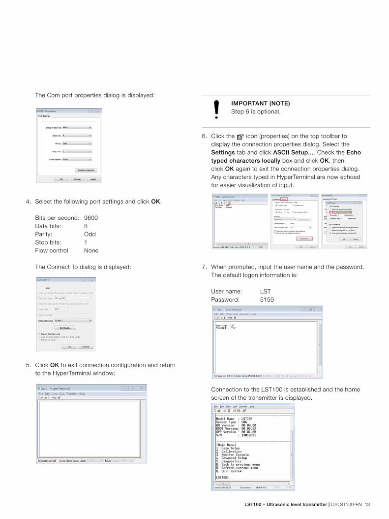
IMPORTANT (NOTE)Step 6 is optional.
6. Click the icon (properties) on the top toolbar to display the connection properties dialog. Select the Settings tab and click ASCII Setup.... Check the Echo typed characters locally box and click OK, then click OK again to exit the connection properties dialog. Any characters typed in HyperTerminal are now echoed for easier visualization of input.
7. When prompted, input the user name and the password. The default logon information is:
User name: LSTPassword: 5159
Connection to the LST100 is established and the home screen of the transmitter is displayed.

14 OI/LST100-EN | LST100 – Ultrasonic level transmitter
4.4 Commissioning the unit4.4.1 Factory settingsThree menu levels are available – Easy, User, and Advanced. All settings found in the Easy Setup menu are also available in the User setup. See Section 4.4.2, Commissioning using the Easy Setup menu for Easy Setup instructions.
The LST100 is delivered with default factory settings as shown in Table 4.1, Factory default settings.
Menu
name
Number Setting Default value
Easy Setup 1 Operate Mode Level
2 Length Unit feet
3 Empty Distance 20.000 ft
4 Span 19.150 ft
5 Blanking 0.850 ft
6 Max Rate of Change 1.500 ft
Calibration 1 Enable User Calibration NO
2 Measured Value of P1 0.003 ft
3 Actual Value of P1 0.003 ft
4 Measured Value of P2 0.003 ft
5 Actual Value of P2 0.003 ft
6 Enable Simulation NO
7 Simulated Voltage 1 mV
8 Offset of 1000mV 1000 mV
9 Offset of 5000mV 5000 mV
Advanced
Setup
1 Measure Interval 2 s
2 Temp. Compensation YES
3 Temp. Unit Fahrenheit
4 Temp. Offset 0.0 F
5 Min Power Level Level_1
6 Max Power Level Level_5
7 Invert Voltage NO
8 Failsafe LOW ALARM
9 Factory Reset NO
10 User Password ********
Table 4.1: Factory default settings
4.4.2 Commissioning using the Easy Setup menuThe most common configuration parameters are summarized in the Easy Setup menu. This menu provides the quickest way to configure the device. Use the Easy Setup menu to select dimensions, operating mode and engineering units.
For a detailed description of these menus and parameters, see Section 5.2, Parameter descriptions.
1. Log on to the LST100 as described in Section 4.1 of this manual. On the welcome screen are 5 menus: Easy, Calibration, Monitor Console, Advanced Setup, and Diagnostics.
2. Select 1 from the Main Menu to display the Easy Setup menu:
3. On the Easy Setup menu, select 1 to configure Operate Mode. The options available are Level and Distance. Select the desired mode by entering the associated number. Click Enter.
4 Commissioning
IMPORTANT (NOTE)After setting a value, select R to refresh the menu with updated settings. Select B to return to the previous menu without refreshing the menu with updated settings.
Level (1) – the LST100 measures the distance from the bottom of the tank to the surface of the liquid.
Span
Blanking
Empty distance
Level
Distance (2) – the LST100 measures the distance from the transmitter to the surface of the liquid.
Span
Blanking
Empty distance
Distance

LST100 – Ultrasonic level transmitter | OI/LST100-EN 15
4. On the Easy Setup menu, select 2 to configure Length Unit. Two options are available, Meters and Feet. Select the preferred unit.
5. On the Easy Setup menu, select 3 to configure Empty Distance. This is the distance (in units selected in step 4) from the face of the sensor to the bottom of the tank. In Level mode, Empty Distance indicates the tank is empty, or the 1V point.
Empty distance
6. On the Easy Setup menu, select 4 to configure Span. This is the distance from the bottom of the blanking distance of the sensor to the bottom of the tank. In Level mode, Span indicates the tank full position, or the 5V point.
Span
IMPORTANT (NOTE)Span cannot be adjusted beyond Blanking. The LST100 limits the Span value based on the Blanking distance set in step 7.
7. On the Main menu, select 5 to configure Blanking. This is the area close to the transmitter where meaningful measurements cannot be made. The default value is according to the product specification. Adjusting Blanking is optional.
Blanking
8. On the Easy Setup menu, select 6 to configure Max Rate of Change. This is the maximum speed at which the level is allowed to change and provides filtering for any brief disturbances.
5 Configuration
The LST100 uses RS485 communication protocol to enable configuration using a laptop computer.
5.1 Menu navigationOn the Main menu there are 8 selectable options. The first 5 are submenus and the last 3 are navigation options.
The submenus:1. Easy Setup contains the most important parameters2. Calibration contains all settings required to calibrate
the measurement or the analog output3. Monitor Console enables access to real time
measurement and instrument status information
4. Advanced Setup contains more advanced parameters not required for common configuration
5. Diagnostics contains all alarms and diagnostic information
Navigation options:Navigation options are displayed in all menu levels. The menu is not case sensitive and accepts upper or lower case input. B. Back to previous return to previous menu menu operation R. Refresh current the menu is refreshed with the menu newest value Q. Quit User is logged off and must log on again before being able to configure the instrument
After sending a command to the LST100, one of three responses are returned:
No. Response status Description
1 Invalid input The input value is out of range.
2 Successful Setting is successful.
3 This item is read only. The item is read only and cannot be
configured.

16 OI/LST100-EN | LST100 – Ultrasonic level transmitter
5.2 Parameter descriptions
Menu summary
Menu name No. Configure name Setting range Description
Easy Setup 1 Operate Mode 1: Level 2: Distance Measurement mode
2 Length Unit 1: Feet 2: Meters Measurement length units
3 Empty Distance 0.213 to 15.24 m (0.700 to 50.00 ft) Distance from sensor to bottom of tank
4 Span 0.213 to 15.24 m (0.700 to 50.00 ft) Measurement span
5 Blanking 0.001 to 15.24 m (0.003 to 50.00 ft) Distance from sensor where no measurement is possible
6 Max Rate of Change 0.001 to 15.24 m/minute
(0.003 to 50.00 ft/minute)
Maximum rate the level can change in the process
Calibration 1 Enable User Calibration 1. No Yes Enable user calibration function
2 Measured Value of P1 0.001 to 15.24 m (0.003 to 50.00 ft) LST100 measured value of calibration point 1 (short range)
3 Actual Value of P1 0.001 to 15.24 m (0.003 to 50.00 ft) Actual distance to target for calibration point 1 (short range)
4 Measured Value of P2 0.001 to 15.24 m (0.003 to 50.00 ft) LST100 measured value of calibration point 2 (short range)
5 Actual Value of P2 0.001 to 15.24 m (0.003 to 50.00 ft) Actual distance to target for calibration point 2 (short range)
6 Enable Simulation 1. No Yes Enable Simulation
7 Simulated Voltage 1 to 5800 mV Simulated Voltage used for output calibration
8 Offset of 1000mV 500 to 1500 mV Offset for 1000 mV
9 Offset of 5000mV 4000 to 6000 mV Offset for 5000 mV
Monitor
Console
1 Level Read Only Output level value
2 Instant Read Only Instant distance from target surface to bottom of tank
3 Percentage Read Only Percentage of Span
4 Voltage Output Read Only The voltage to output
5 Refresh Automatically 1. No Yes Refresh automatically
Advanced
Setup
1 Measure Interval 2 to 3600 s Interval between measurements
2 Temp. Compensation 1. No Yes Compensate for the speed of sound
3 Temp. Unit 1. Fahrenheit Celsius Temperature unit
4 Temp. Offset -200 to 200 Offset for temperature sensor
5 Min Power Level 1. Level_1
2. Level_2
3. Level_3
4. Level_4
5. Level_5
Minimum power used
6 Max Power Level 1. Level_1
2. Level_2
3. Level_3
4. Level_4
5. Level_5
Maximum power used
7 Invert Voltage 1. No Yes Invert voltage
8 Failsafe 1. LOW ALARM
2. HIGH ALARM
3. HOLD MODE
Failsafe
9 Factory Reset 1. No Yes Factory reset
10 User Password Read Only
5 Configuration

LST100 – Ultrasonic level transmitter | OI/LST100-EN 17
Menu summary
Menu name No. Configure name Setting range Description
Diagnostics 1 Temperature Read Only Indicate the current temperature
2 Signal Level Read Only Indicate the average signal in last measurement
3 Maximum Signal Read Only Indicate the maximum signal in last measurement
4 Noise Level Read Only Indicate the average noise in last measurement
5 Maximum Noise Read Only Indicate the maximum noise in last measurement
6 Signal Noise Ratio Read Only Indicate the ratio of the signal size to the noise size
7 Number of Echo Read Only Indicate the number of echoes in last measurement
8 Current Pulse Number Read Only Indicate the number of pulses being transmitted
9 Current Gain Read Only Indicate the current receiver gain
10 Current Power Mode Read Only Indicate the high power or low power in use for pulsing
11 Current Blanking Read Only Indicate the curent blanking
12 Number of Power Change Read Only Indicate the number of power change
13 Alarm Level Read Only Indicate the the alarm level
14 NV Status Read Only Indicate the NV statue
15 NV Load Error Read Only Indicate the NV load error
16 Power Down Alarm Read Only Indicate the power shut down, but device dosen't restart
17 Almost Full Read Only Indicate the distance may be not able to measure
18 Loss Signal Read Only Indicate the echo has lost for a long time
19 Beyond Empty Dis. Read Only Indicate the distance is out of empty distance
20 Loss Echo Read Only Indicate the echo is loss
21 Echo Too Small Read Only Indicate the maximum signal is below value of echo too small
22 Echo Too Large Read Only Indicate the maximum signal is above value of echo too large
23 Temp. High Read Only Indicate the the temperature is too high
24 Temp. Low Read Only Indicate the the temperature is too low
25 Noise Alarm Read Only Indicate the the average noise is above noise threshold
26 Clear NV Load Error 1. No Yes Clear NV load error

18 OI/LST100-EN | LST100 – Ultrasonic level transmitter
5.3 Downloading and uploading configurationsTo download a device configuration:1. Log on to the LST100 using the following logon information:
User name: LSTCONFIGPassword: 5159
5 Configuration
IMPORTANT (NOTE)The password 5159 is the default user password. If the user password has been customized, use the updated password.
After successfully logging on, the LST100 responds with the current device configuration in the following format:
---Start of configuration file--- { >1=1\r >2=2\r >3=3\r >4=4\r >5=5\r … } ---End of configuration file---
2. Select the text shown in red above.
3. Copy the text and paste it into a text editor (for example, Notepad).
4. Save the file to a known location as a configuration backup or for upload to another device.
To upload a device configuration:1. Log on to the LST100 using the following logon information:
User name: LSTCONFIGPassword: 5159
IMPORTANT (NOTE)The password 5159 is the default user password. If the user password has been customized, use the updated password.
2. Select Transfer in the HyperTerminal toolbar and select Send Text File... to open the file explorer window.
3. In the file explorer window, browse to the configuration file saved at step 4 in the download instructions. Select the file and click Open. HyperTerminal sends the configuration to the LST100.
4. The LST100 responds with a status message indicating upload success or failure in the following format:
---Start of response message--- There is not nv error now. <0>1=1\r <0>2=2\r <0>3=3\r <0>4=4\r <0>5=5\r … ---End of response message---
5. Enter Q (or q) to exit the upload interface.

LST100 – Ultrasonic level transmitter | OI/LST100-EN 19
An easy-to-use, 2-point calibration enables the best possible accuracy by calibrating the measurement to two known good points.
There are two types of errors: offset and gradient.
– Offset error The error at close range is equal to the error at maximum range. In this case the “c” value in the equation y=mx+c must be corrected.
10.1 ft.
1.1 ft.
1 ft. 10 ft.Real distance
Measured distance
y=mx+c
– Gradient error A small error at a close range becomes larger as the range increases. In this case the “m” value in the equation y=mx+c must be corrected.
10.1 ft.
1.01 ft.
1 ft. 10 ft.Real distance
Measured distance
y=mx+c
The speed of sound is linear, enabling calibration to be performed using only 2 known points. This provides sufficient information to calibrate LST100.
6.1 Calibration procedureCalibration can be performed on site if the tank dimensions are known. This gives best results as it ensures the instrument is calibrated to the intended installation. Alternatively, the calibration can be performed before installation by pointing the sensor at a known target.
1. Log on to the LST100 as described in Section 4.3, Configuring the digital communications. The welcome screen is displayed.
2. Select 1. Easy Setup from the main menu. Ensure that Operate Mode is set to Distance.
Enter B to return to the main menu.
3. Select Calibration from the main menu. Ensure that Enable User Calibration is set to NO. This disables any existing calibration to avoid errors in the new calibration.
Enter B to return to the main menu.
6 Calibration

20 OI/LST100-EN | LST100 – Ultrasonic level transmitter
4. Ensure the LST100 is measuring the short range calibration point and select 3. Monitor Console from the main menu.
Record the measured distance and the actual distance.
6 Calibration
IMPORTANT (NOTE)ABB recommends measuring the short range calibration point when the tank is nearly full.
5. Ensure the LST100 is measuring the long range calibration point and select 3. Monitor Console from the main menu. Record the measured distance and the actual distance.
IMPORTANT (NOTE)ABB recommends measuring the long range calibration point when the tank is empty.
Enter B to return to the main menu.
6. Select 2. Calibration from the main menu. Configure the following 4 parameters from the information noted in Steps 4 and 5:
Measured value of P1: The measured short range distance noted at Step 4
Actual value of P1: The actual short range distance noted at Step 4
Measured value of P2: The measured long range distance noted at Step 4
Actual value of P2: The actual long range distance noted at Step 4
7. Set Enable User Calibration to YES. The calibration is now active on the LST100.
Enter B to return to the main menu.
8. Select 3. Monitor Console from the main menu. Check that the distance is within the LST100 transmitter’s specified accuracy.
IMPORTANT (NOTE)Step 9 is applicable only if Operate Mode was set to Level before calibration was performed.
9. Select 1. User Setup from the main menu and set Operate Mode to Level (if required).

LST100 – Ultrasonic level transmitter | OI/LST100-EN 21
The LST100 provides several diagnostic messages that can be viewed from the menu. The diagnostic messages provide insight into the state of the current process and can be valuable when troubleshooting an application.
Table 7.1 details each diagnostic message together with possible causes and remedial actions.
Alarm
number
Name on
HyperTerminal
Cause Remedy
1 Temperature Current Temperature
2 Signal Level Average signal in last measurement
3 Maximum Signal Maximum signal in last measurement
4 Noise Level Average noise in last measurement
5 Maximum Noise Maximum noise in last measurement
6 Signal Noise Ratio The ratio of the signal size to the noise size
7 Number of Echo The number of echoes in last measurement
8 Current Pulse Number The number of pulses being transmitted
9 Current Gain The current receiver gain
10 Current Power Mode High power or low power in use for pulsing
11 Current Blanking The selected blanking, Blanking or Blanking
for HP
12 Number of Power
Change
Number of changes to instrument pulsing
and receiving power in the last minute
13 Alarm Level Device alarm level
14 NV Status Status of NV operations
15 NV Load Error 1. The NV (nonvolatile memory)
initialization has failed.
2. The firmware has been updated.
1. Set the Clear NV Load Error parameter to Yes to clear the
nonvolatile memory.
2. Restart the LST100.
16 Power Down Alarm Power supply is below the minimum of 9 V. Ensure the power supply voltage is above 9 V.
17 Almost Full The distance to the target surface is
approaching the Blanking parameter value.
Measurement has stopped and a Tank Full
state is transmitted (5 V).
1. Increase the distance to the target surface.
2. Increase the value of the Blanking parameter.
18 Loss Signal Loss Echo lasts for several minutes. 1. Reduce the distance to the target surface.
2. Contact ABB service.
19 Beyond Empty Dis. The distance to the target surface is beyond
the Empty Distance setting.
1. Reduce the distance to the target surface.
2. Increase the value of the Empty Distance parameter.
20 Loss Echo The distance to the target surface is beyond
the measurement range.
1. Reduce the distance to the target surface.
2. Ensure the LST100 is installed perpendicular to the target surface.
21 Echo Too Small 1. The distance to the target surface is
approaching the measurement limit.
2. The Max Power Level setting in the User
Setup menu is too low.
1. Reduce the distance to the target surface.
2. Increase the value of the Max Power Level parameter.
22 Echo Too Large The Min Power Level setting in the User
Setup menu is too high.
Decrease the value of the Max Power Level parameter.
23 Temp. High The environment temperature is too high. Check and decrease the environment temperature.
24 Temp. Low The environment temperature is too low. Check and increase the environment temperature.
25 Noise Alarm The noise level is too high. Decrease the value of the Max Power Level parameter.
26 Clear NV Load Error Clear nonvolatile memory load error
Table 7.1: Diagnostic messages
7 Diagnostic messages

22 OI/LST100-EN | LST100 – Ultrasonic level transmitter
MeasurementRange0.85 to 20 ft / 1.15 to 30 ft
Beam angle (@ –3dB)5° (20 ft version) / 7° (30 ft version)
Accuracy±½ in. or 0.25 % of full span (largest of the two)
Repeatability±0.25% of measurement range
Mechanical dataHousing materialPVDF
DimensionsHeight – 122 mm (4.8 in.) minimum (excluding glands)Diameter – 78 mm (3.07 in.) – excluding glands
Weight1.0 kg (2.2 lb)
Cable entry typeOne ½ in. threaded bore for cable gland, directly on housingSupplied with 1 x ½ in. NPT cable gland
Electrical DataTerminals9 terminals for power supply and communication purposes accommodating wire cross sections of up to 1 in. (14 AWG)
Power supply3 terminals for power supply (PE/+/–): The LST100 operates from 9 to 16 V DC and is protected against reversed polarity
Analog output (1 to 5 V)2 terminals for analog output (+/–): 1 to 5 V related to level, or full compensation for temperature effects
RS485 communication2 terminals for RS485 communication (+/–): RS485 communication for setting parameters, monitoring measurement results and diagnostics messages
Option for connecting ground2 terminals as a jumper switch for ground earth. Connecting the transducer to ground is optional and is done using this jumper.
Environmental dataHazardous area approvalsIntrinsic Safety type of protection: – Approval according to FM US and Canada – IS Class 1 Div 1/GP ABCD- CL II/ DIV 1/ GP EFG, CL 1, Zone 1
Non Incendive type of protection: – Approval according to FM US and Canada – NI Class 1 Div 2/GP ABCD- DIP CL II/ DIV 2/ GP EFG, CL
1, Zone 2, AExnA IIC T6; IP66/67
Electromagnetic compatibility (EMC)Meets requirements of EN 61326Overvoltage strength (with surge protection): 2 kV (according to IEC 61000-4-5)
Temperature-40 to 185 °F, according to EN 60068-2-14, 1K/min, 100 cycles
HumidityRelative humidity: Up to 100 % Condensation, icing: Not permissible
PressureMeasurement functional from –4 to 44 psi (–0.25 to 3.0 bar)
Vibration resistanceAcceleration up to 1 g at frequencies of up to 2,000 Hz (according to IEC 60068-2-64)
Humid and dusty atmospheres (degree of protection)LST100 is dust and sand-proof and protected against immersion effects as defined by EN 60529 (1989) to IP 66/67 or by NEMA 4X
8 Specifications

LST100 – Ultrasonic level transmitter | OI/LST100-EN 23
Notes
Contact us
ABB Inc.Upstream Oil & GasProcess AutomationToll-free: + 1 800 442 3097 Quotes: [email protected] Orders: [email protected] Training: [email protected] Support: [email protected]
Upstream Oil & GasMain Office7051 Industrial Boulevard Bartlesville, OK 74006 Ph: +1 918 338 4888
Upstream Oil & GasCalifornia Office4300 Stine Road, Suite 405-407 Bakersfield, CA 93313 Ph: +1 661 833 2030
Upstream Oil & GasKansas Office2705 Centennial Boulevard Liberal, KS 67901 Ph: +1 620 626 4350
Upstream Oil & GasTexas Offices3700 West Sam Houston Parkway South, Suite 600 Houston, TX 77042 Ph: +1 713 587 8000
3900 South County Road 1290 Odessa, TX 79765 Ph: +1 432 563 5144
150 Eagle Ford Road Pleasanton, TX 78064 Ph: +1 830 569 8062
www.abb.com/upstream
Note We reserve the right to make technical changes or modify the contents of this document without prior notice. With regard to purchase orders, the agreed particulars shall prevail. ABB does not accept any responsibility whatsoever for potential errors or possible lack of information in this document.
We reserve all rights in this document and in the subject matter and illustrations contained therein. Any reproduction, disclosure to third parties or utilization of its contents – in whole or in parts – is forbidden without prior written consent of ABB.
Copyright © 2016 ABB Inc. All rights reserved
Product webpage
OI/
LST1
00-E
N –
Rev
. A
C
03.2
016