Embed Size (px)
Citation preview

Products Solutions ServicesBA01225C/07/EN/02.1371238292
Valid as of:Softwareversion 01.05.00
Operating InstructionsLiquiline CM442R/CM444R/CM448R
Universal four-wire multichannel controller for cabinet installation


Endress+Hauser
Liquiline CM442R/CM444R/CM448R
Table of contents
1 Document information . . . . . . . 51.1 Warnings . . . . . . . . . . . . . . . . . . . . . . . . . . 51.2 Symbols used . . . . . . . . . . . . . . . . . . . . . . . 51.3 Documentation . . . . . . . . . . . . . . . . . . . . . 6
2 Basic safety instructions . . . . . . 72.1 Requirements for personnel . . . . . . . . . . . 72.2 Designated use . . . . . . . . . . . . . . . . . . . . . . 72.3 Occupational safety . . . . . . . . . . . . . . . . . . 82.4 Operational safety . . . . . . . . . . . . . . . . . . . 82.5 Product safety . . . . . . . . . . . . . . . . . . . . . . 9
3 Device description . . . . . . . . . . 103.1 Overview . . . . . . . . . . . . . . . . . . . . . . . . . . 103.2 Device architecture . . . . . . . . . . . . . . . . . 11
4 Incoming acceptance and product identification . . . . . . . 13
4.1 Incoming acceptance . . . . . . . . . . . . . . . . 134.2 Product identification . . . . . . . . . . . . . . . 134.3 Scope of delivery . . . . . . . . . . . . . . . . . . . 144.4 Certificates and approvals . . . . . . . . . . . 14
5 Installation . . . . . . . . . . . . . . . . 155.1 Installation conditions . . . . . . . . . . . . . . 155.2 Mounting the measuring device . . . . . . 185.3 Post-installation check . . . . . . . . . . . . . . 21
6 Electrical connection . . . . . . . . 226.1 Connection conditions . . . . . . . . . . . . . . 226.2 Connecting the measuring device . . . . . 256.3 Connecting the sensors . . . . . . . . . . . . . . 286.4 Connecting additional inputs, outputs or
relays . . . . . . . . . . . . . . . . . . . . . . . . . . . . . 316.5 Connecting digital communication . . . . 356.6 Hardware settings . . . . . . . . . . . . . . . . . . 376.7 Guaranteeing the degree of protection . 376.8 Post-connection check . . . . . . . . . . . . . . 38
7 System integration. . . . . . . . . . 397.1 Web server . . . . . . . . . . . . . . . . . . . . . . . . 397.2 Service interface . . . . . . . . . . . . . . . . . . . . 417.3 Fieldbuses . . . . . . . . . . . . . . . . . . . . . . . . . 42
8 Operation options . . . . . . . . . . 438.1 Overview . . . . . . . . . . . . . . . . . . . . . . . . . . 438.2 Access to the operating menu via the
local display . . . . . . . . . . . . . . . . . . . . . . . . 448.3 Configuration options . . . . . . . . . . . . . . . 45
9 Commissioning . . . . . . . . . . . . . 489.1 Function check . . . . . . . . . . . . . . . . . . . . . 489.2 Switching on the unit . . . . . . . . . . . . . . . . 489.3 Basic setup . . . . . . . . . . . . . . . . . . . . . . . . . 50
10 Operation. . . . . . . . . . . . . . . . . . 5110.1 Display . . . . . . . . . . . . . . . . . . . . . . . . . . . . 5110.2 General settings . . . . . . . . . . . . . . . . . . . . 5410.3 Current inputs . . . . . . . . . . . . . . . . . . . . . . 6710.4 Outputs . . . . . . . . . . . . . . . . . . . . . . . . . . . 6810.5 Binary inputs and outputs . . . . . . . . . . . . 7610.6 Additional functions . . . . . . . . . . . . . . . . . 84
11 Diagnostics and troubleshooting . . . . . . . . . . . 113
11.1 General troubleshooting . . . . . . . . . . . 11311.2 Diagnostic information on the local
display (optional) . . . . . . . . . . . . . . . . . 11411.3 Diagnostic information via web
browser . . . . . . . . . . . . . . . . . . . . . . . . . 11411.4 Diagnostic information via fieldbus . . 11411.5 Adjusting diagnostic information . . . . 11511.6 Overview of diagnostic information . . 11811.7 Pending diagnostic messages . . . . . . . 12111.8 Diagnostics list . . . . . . . . . . . . . . . . . . . 12111.9 Event logbook . . . . . . . . . . . . . . . . . . . . 12111.10 Simulation . . . . . . . . . . . . . . . . . . . . . . 12511.11 Reset measuring instrument . . . . . . . 12611.12 Device information . . . . . . . . . . . . . . . 12711.13 Firmware history . . . . . . . . . . . . . . . . . 129
12 Maintenance . . . . . . . . . . . . . . 13012.1 Calibration . . . . . . . . . . . . . . . . . . . . . . . 13012.2 Cleaning . . . . . . . . . . . . . . . . . . . . . . . . . 131

Liquiline CM442R/CM444R/CM448R
4
13 Repair. . . . . . . . . . . . . . . . . . . . 13313.1 Spare parts . . . . . . . . . . . . . . . . . . . . . . . 13313.2 Return . . . . . . . . . . . . . . . . . . . . . . . . . . . 13613.3 Disposal . . . . . . . . . . . . . . . . . . . . . . . . . 136
14 Accessories . . . . . . . . . . . . . . . 13714.1 Measuring cable . . . . . . . . . . . . . . . . . . 13714.2 Sensors . . . . . . . . . . . . . . . . . . . . . . . . . . 13814.3 Additional functionality . . . . . . . . . . . . 14214.4 Software . . . . . . . . . . . . . . . . . . . . . . . . . 14414.5 Other accessories . . . . . . . . . . . . . . . . . 144
15 Technical data . . . . . . . . . . . . 14615.1 Input . . . . . . . . . . . . . . . . . . . . . . . . . . . . 14615.2 Digital inputs, passive . . . . . . . . . . . . . . 14715.3 Current input, passive . . . . . . . . . . . . . 14715.4 Output . . . . . . . . . . . . . . . . . . . . . . . . . . 14815.5 Digital outputs, passive . . . . . . . . . . . . 15015.6 Current output, active . . . . . . . . . . . . . . 15115.7 Relay outputs . . . . . . . . . . . . . . . . . . . . . 15215.8 Protocol-specific data . . . . . . . . . . . . . . 15315.9 Power supply . . . . . . . . . . . . . . . . . . . . . 15615.10 Performance characteristics . . . . . . . . 15715.11 Environment . . . . . . . . . . . . . . . . . . . . 15815.12 Mechanical construction . . . . . . . . . . . 160
Index . . . . . . . . . . . . . . . . . . . . 161
Liquiline CM442R/CM444R/CM448R Document information
Endress+Hauser 5
1 Document information
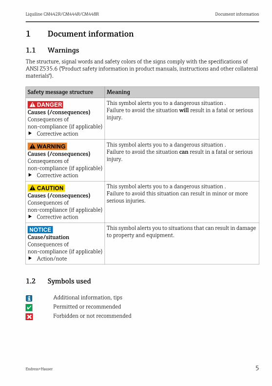
1.1 WarningsThe structure, signal words and safety colors of the signs comply with the specifications of ANSI Z535.6 ("Product safety information in product manuals, instructions and other collateral materials").
1.2 Symbols used
Safety message structure Meaning
DANGER!
Causes (/consequences)Consequences of non-compliance (if applicable)‣ Corrective action
This symbol alerts you to a dangerous situation .Failure to avoid the situation will result in a fatal or serious injury.
WARNING!
Causes (/consequences)Consequences of non-compliance (if applicable)‣ Corrective action
This symbol alerts you to a dangerous situation .Failure to avoid the situation can result in a fatal or serious injury.
CAUTION!
Causes (/consequences)Consequences of non-compliance (if applicable)‣ Corrective action
This symbol alerts you to a dangerous situation .Failure to avoid this situation can result in minor or more serious injuries.
NOTICECause/situationConsequences of non-compliance (if applicable)‣ Action/note
This symbol alerts you to situations that can result in damage to property and equipment.
Additional information, tips
Permitted or recommended
Forbidden or not recommended

Document information Liquiline CM442R/CM444R/CM448R
6 Endress+Hauser
1.3 DocumentationAs a supplement to these Operating Instructions the following manuals are available on the CD-ROM:• Brief Operating Instructions Liquiline CM44xR, KA01160C• Operating Instructions Memosens, BA01245C
– Software description for Memosens inputs– Calibration of Memosens sensors– Sensor-specific diagnostics and troubleshooting
• Operating Instructions for HART communication, BA00486C– Onsite settings and installation instructions for HART– Description of HART drivers
• Guidelines for communication via fieldbus and web server– HART, SD01187C– PROFIBUS, SD01188C– Modbus, SD01189C– Web server, SD01190C
The CD also contains:• Technical Information Liquiline CM44xR, TI01112C• Documentation for other devices in the Liquiline family:
– Liquiline CM44x (field device)– Liquistation CSFxx and Liquiport CSP44 (sampler)
• Simulation software

Liquiline CM442R/CM444R/CM448R Basic safety instructions
Endress+Hauser 7
2 Basic safety instructions
2.1 Requirements for personnel‣ Installation, commissioning, operation and maintenance of the measuring system must only
be carried out by specially trained technical personnel.‣ The technical personnel must be authorized for the specified activities by the system
operator.‣ Electrical connection must only be carried out by a certified electrician.‣ The technical personnel must have read and understood these Operating Instructions and
must adhere to them.‣ Faults at the measuring point may only be rectified by authorized and specially trained
personnel.
Repairs that are not described in these Operating Instructions must only be carried out directly at the manufacturer or by the service organization.
2.2 Designated use
2.2.1 Non-hazardous atmosphere
Liquiline CM44xR is a multichannel controller for connecting digital sensors with Memosens technology in non-hazardous environments.
The device is designed for use in the following applications:• Food and beverages• Life science• Water and wastewater• Chemical industry
2.2.2 Non-designated use and
NOTICEObjects stored on top of the housingMay cause a short-circuit or fire. Failure of individual cabinet components or complete failure of the measuring point is possible‣ Never place any objects such as tools, cables, paper, food, liquid containers etc. on top of the
housing.‣ Always comply with the operator's instructions particularly regarding fire prevention
(smoking) and handling foodstuffs (beverages).
Any other use than the one described here compromises the safety of persons and the entire measuring system and is not permitted.The manufacturer is not liable for damage caused by improper or non-designated use.

Basic safety instructions Liquiline CM442R/CM444R/CM448R
8 Endress+Hauser
2.2.3 Installation environment
The device and the associated power units can be operated with 24 V AC, 24 V DC or 100 to 230 V AC and provide IP20 shock protection. The components have been designed for pollution level 2, and moisture must not be allowed to collect in them. For this reason the components must be installed in an appropriate enclosure for protection. When installing, please observe the ambient conditions specified in the manual.
2.3 Occupational safetyAs the user, you are responsible for complying with the following safety conditions:• Installation instructions• Local standards and regulations
Electromagnetic compatibilityThe product has been tested for electromagnetic compatibility in accordance with the applicable European standards for industrial applications.The electromagnetic compatibility indicated only applies to a product that has been connected in accordance with the instructions in these Operating Instructions.
2.4 Operational safety‣ Prior to commissioning the entire measuring point, check that all connections are correct.
Ensure that electrical cables and hose connections are not damaged.‣ Do not operate damaged products, and secure them against unintentional commissioning.
Label and identify the damaged product as being defective.‣ If faults cannot be rectified, the products must be taken out of service and secured against
unintentional commissioning.
CAUTION!
The cleaning system is not switched off during calibration or maintenance activitiesRisk of injury due to medium or cleaning agent‣ If a cleaning system is connected, switch it off before removing a sensor from the medium.‣ If you are not switching off the cleaning system because you wish to test the cleaning
function, wear protective clothing, goggles and gloves or take other appropriate measures.

Liquiline CM442R/CM444R/CM448R Basic safety instructions
Endress+Hauser 9
2.5 Product safety
2.5.1 State of the art
The transmitter is designed to meet state-of-the-art safety requirements, has been tested and left the factory in a condition in which it is safe to operate.Relevant regulations and European standards have been observed.
2.5.2 IT security
We only provide a warranty if the device is installed and used as described in the Operating Instructions. The device is equipped with security mechanisms to protect it against any inadvertent changes to the device settings.IT security measures in line with operators' security standards and designed to provide additional protection for the device and device data transfer must be implemented by the operators themselves.Support in the performance of this task can be requested from Endress+Hauser.

Device description Liquiline CM442R/CM444R/CM448R
10 Endress+Hauser
3 Device description
3.1 Overview
a0020573
Fig. 1: CM44xR with optional, external display (excluding cables)1234
CM448R1)
Extension modules (optional)Shock protection, dummy moduleTerminal strip
1) CM444R: same housing, other extension modules
5678
External display (optional)Base moduleCM442RExternal power unit (CM444R or CM448R only)

Liquiline CM442R/CM444R/CM448R Device description
Endress+Hauser 11
3.2 Device architecture
3.2.1 Slot and port assignment
a0019832
a0019833
Fig. 2: Slot and port assignment of the hardware modules
Fig. 3: Slot and port assignment on the display
• Inputs are assigned to measuring channels in ascending order of the slots and ports.Adjacent example:If "CH1: 1:1 pH glass" is displayed, this means:Channel 1 (CH1) is slot 1 (base module) : port 1 (input 1), pH glass sensor
• The outputs and relays are named after their function, e.g. "Current output", and are displayed with the slot and port numbers in ascending order
Device description Liquiline CM442R/CM444R/CM448R
12 Endress+Hauser
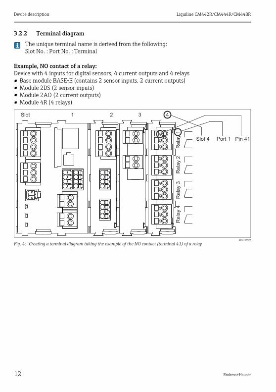
3.2.2 Terminal diagram
The unique terminal name is derived from the following:Slot No. : Port No. : Terminal
Example, NO contact of a relay:Device with 4 inputs for digital sensors, 4 current outputs and 4 relays• Base module BASE-E (contains 2 sensor inputs, 2 current outputs)• Module 2DS (2 sensor inputs)• Module 2AO (2 current outputs)• Module 4R (4 relays)
a0015979
Fig. 4: Creating a terminal diagram taking the example of the NO contact (terminal 41) of a relay

Liquiline CM442R/CM444R/CM448R Incoming acceptance and product identification
Endress+Hauser 13
4 Incoming acceptance and product identification
4.1 Incoming acceptance1. Make sure the packaging is undamaged.
Inform the supplier about any damage to the packaging.
Keep the damaged packaging until the matter has been settled.
2. Make sure the contents are undamaged.
Inform the supplier about damage to the contents.
Keep the damaged products until the matter has been settled.
3. Check that the delivery is complete and nothing is missing.
Compare the scope of delivery against the delivery papers and your order.
4. Pack the product in such a way as to protect it reliably against impact and moisture for storage and transportation.
The original packaging offers the best protection.
Keep to the approved ambient conditions (see "Technical data").
If you have any questions, contact your supplier or your local sales center.
4.2 Product identification
4.2.1 Nameplate
Nameplates can be found:• On the outside of the DIN rail housing• On the packaging (adhesive label, portrait format)• On the rear of the external display (covered over when installed)
The nameplate provides you with the following information on your device:• Manufacturer ID• Order code• Extended order code• Serial number• Firmware version• Input and output variables• Protection class• Ambient conditions• Activation codes• Safety notices and warnings
Compare the data on the nameplate with your order.
Incoming acceptance and product identification Liquiline CM442R/CM444R/CM448R
14 Endress+Hauser
4.2.2 Identifying the product
The order code and serial number of your device can be found in the following locations:• On the nameplate• In the delivery papers
To find out the version of your device, enter the order code indicated on the nameplate in the search screen at the following address:www.products.endress.com/order-ident
4.3 Scope of delivery• 1 controller in the version ordered• 1 external display (optional)• 1 DIN rail power unit incl. cable (only CM444R and CM448R)• 1 printed copy of Operating Instructions for DIN rail power unit• 1 CD with Operating Instructions• 1 printed copy of the Brief Operating Instructions in the language ordered
If you have any questions, contact your supplier or your local sales center.
4.4 Certificates and approvals
4.4.1 CE mark: Declaration of Conformity
With this declaration, the manufacturer guarantees that the product conforms to the regulations of European Directive 2004/108/EC concerning electromagnetic compatibility and Low Voltage Directive 2006/95/EC. This is proven by observing the standards listed in the Declaration of Conformity.
4.4.2 cCSAus
Application has been submitted

Liquiline CM442R/CM444R/CM448R Installation
Endress+Hauser 15
5 Installation
5.1 Installation conditions
5.1.1 DIN rail mounting
CAUTION!
Power unit can become very hot when operating at full loadDanger of burns‣ Avoid touching the power unit when it is in operation.‣ The required minimum distances from other devices must be strictly observed.‣ Once you have switched off the power unit, wait until it has cooled down before carrying out
any work on it.
CAUTION!
Unpermitted moisture in the devicePuts the user's safety at risk‣ The device has shock protection in accordance with IP20. Moisture must not be allowed to
collect in the device.‣ Observe the specified ambient conditions e.g. by installing in an appropriate enclosure.
NOTICEIncorrect mounting location in control cabinet, distances not observedPossible functional failures due to heat buildup, interference from neighboring devices‣ Do not place the device directly above heat sources. The temperature specifications must be
strictly observed.‣ The components are designed for cooling through convection. Avoid heat buildup and
ensure that openings are not covered e.g. by cables lying on top of them.‣ Observe the specified distances from other devices.‣ Keep the device physically separate from frequency converters and high-voltage devices.‣ Recommended installation direction: horizontal. The specified ambient conditions, in
particular the ambient temperatures, apply here only.‣ A vertical orientation is possible. However, in this case, additional fixing clips are required
at the place of installation to keep the device in position on the DIN rail.‣ Recommended installation of power unit for CM444R and CM448R: to the left of the device.
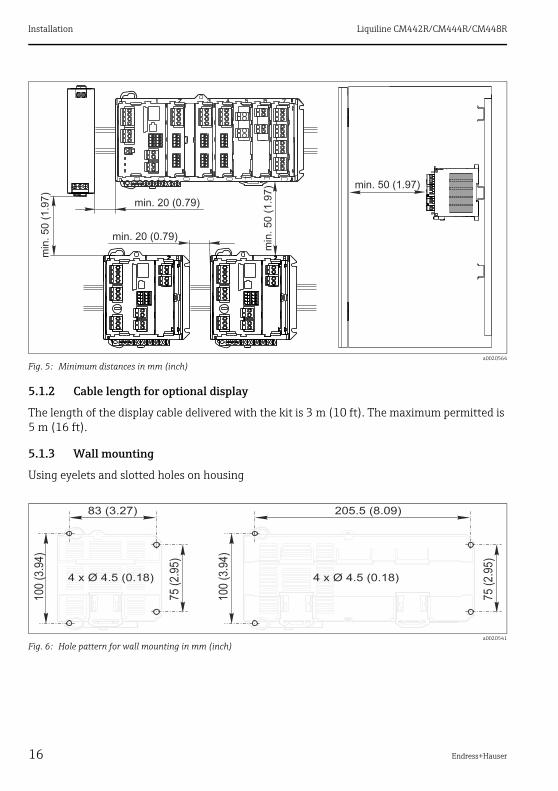
The following minimum distances must be observed:• Laterally from other devices incl. power units and from wall of cabinet:
at least 20 mm (0.79 inch)• above, below, in front of and behind the device (from cabinet door or other devices installed
there):at least 50 mm (0.79 inch)
Installation Liquiline CM442R/CM444R/CM448R
16 Endress+Hauser
5.1.2 Cable length for optional display
The length of the display cable delivered with the kit is 3 m (10 ft). The maximum permitted is 5 m (16 ft).
5.1.3 Wall mounting
Using eyelets and slotted holes on housing
a0020564
Fig. 5: Minimum distances in mm (inch)
a0020541
Fig. 6: Hole pattern for wall mounting in mm (inch)
Liquiline CM442R/CM444R/CM448R Installation
Endress+Hauser 17
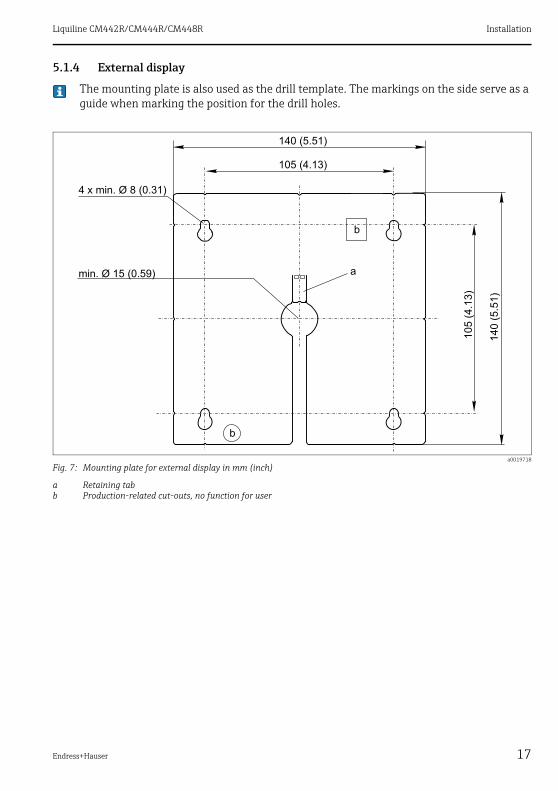
5.1.4 External display
The mounting plate is also used as the drill template. The markings on the side serve as a guide when marking the position for the drill holes.
a0019718
Fig. 7: Mounting plate for external display in mm (inch)
a Retaining tabb Production-related cut-outs, no function for user

Installation Liquiline CM442R/CM444R/CM448R
18 Endress+Hauser
5.2 Mounting the measuring device
5.2.1 DIN rail mounting
The mounting procedure is the same for all devices. The example shows a CM448R.
In the order configuration, the securing clips are "tightened" to secure the DIN rail.
1. Release the securing clips by pulling them downwards.
2. Attach the device from the top to the DIN rail (a) and then press it down to secure it (b).
3. Slide the securing clips upwards until they click, thereby securing the device to the DIN rail.
Only CM444R and CM448R
4. Mount the external power unit in the same way.

Liquiline CM442R/CM444R/CM448R Installation
Endress+Hauser 19
5.2.2 Wall mounting
Mounting material (screws, dowels) are not included in the scope of delivery and must be provided by the customer.CM444R and CM448R: The external power unit can only be mounted on a DIN rail.
Use the back of the housing to mark the mounting holes (→ å 6).
1. Drill the required holes and place dowels in them if necessary.
2. Screw the housing onto the wall.
5.2.3 Mounting the optional external display
CAUTION!
Sharp-edged, non-deburred drill holesRisk of injury, display cable may get damaged‣ In particular, deburr the central drill hole for the display cable.
a0019870
Fig. 8: Fully mounted display
Mounting the display on the door of the cabinetTo do this, use the mounting plate as a drill template. In addition, you will need a pen to mark the drill holes, as well as a serrated edge rule and a drill.
1. Hold the mounting plate from the outside against the door of the control cabinet. Choose the point at which you wish to install the display.
2. Make all the markings.
3. Draw lines connecting the markings.
This will indicate the position of the five drill holes needed.
4. Drill the holes (→ å 7).
5. Pull the display cable through the hole in the middle, and place the display from the outside through the 4 holes drilled for this purpose, ensuring that the torx screws have been unscrewed to the last half turn but are still in place.
6. Connect the display cable to the RJ-45 socket in the base module.
7. Place the mounting plate (a) on the inside over the screws, slide it down (b) and tighten the screws (c).
The display is now mounted and ready to use.

Installation Liquiline CM442R/CM444R/CM448R
20 Endress+Hauser
a0019871 a0019872
a0019873 a0019874
a0019903 a0019881

Liquiline CM442R/CM444R/CM448R Installation
Endress+Hauser 21
5.3 Post-installation check1. Following installation, check all devices (controller, power unit, display) for damage.
2. Verify that the specified mounting distances have been observed.
3. Verify that all securing clips have been snapped into place and that the components are securely positioned on the DIN rail.
4. Ensure that the temperature limits at the mounting location are observed.
a0019880
NOTICEInstallation errorsDamage e.g. to the cable, or malfunctions‣ Lay the cables in such a way that they cannot get
squashed e.g. when closing the cabinet door.‣ Verify that you have actually put the display cable into
the RJ45 socket in the base module and not, for example, into the Ethernet socket of the (optional) module 485. Otherwise, your display will not function.

Electrical connection Liquiline CM442R/CM444R/CM448R
22 Endress+Hauser
6 Electrical connectionWARNING!
The device is live!Incorrect wiring can result in injury or fatality‣ The electrical connection may only be established by an electrical technician.‣ The electrical technician must have read and understood these Operating Instructions and
must follow the instructions they contain.‣ Prior to beginning any wiring work, make sure voltage is not applied to any of the cables.
NOTICEFaulty cable runCable damage due to absence of strain relief, faults on signal lines‣ Run all cables through the cable channels of the cabinet to the terminals.‣ Run the signal cables to the terminals separately from the live cables.
6.1 Connection conditions
6.1.1 Remote operation via HART (e.g. via HART modem and FieldCare)
a0015608
Fig. 9: HART via modem
1 Base-L, -H or -E device module: current output 1 with HART2 HART modem for connecting to PC, e.g. FXA1951)
3 HART handheld terminal
1) Switch set to "on" (substitutes the resistor)

Liquiline CM442R/CM444R/CM448R Electrical connection
Endress+Hauser 23
6.1.2 Remote operation via PROFIBUS DP
a0015874
Fig. 10: PROFIBUS DP
T Terminating resistor
Electrical connection Liquiline CM442R/CM444R/CM448R
24 Endress+Hauser
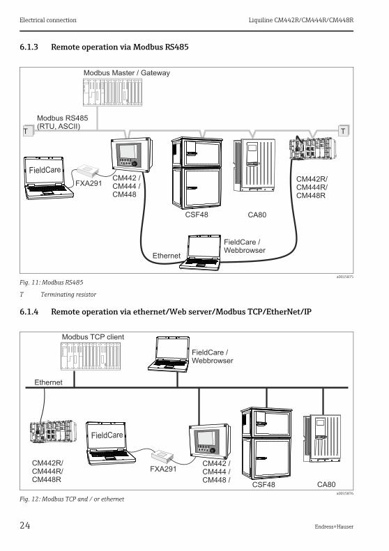
6.1.3 Remote operation via Modbus RS485
6.1.4 Remote operation via ethernet/Web server/Modbus TCP/EtherNet/IP
a0015875
Fig. 11: Modbus RS485
T Terminating resistor
a0015876
Fig. 12: Modbus TCP and / or ethernet

Liquiline CM442R/CM444R/CM448R Electrical connection
Endress+Hauser 25
6.2 Connecting the measuring device
WARNING!
The device is live!Incorrect wiring can result in injury or fatality‣ Prior to beginning any wiring work, make sure voltage is not applied to any of the cables.
NOTICEThe device does not have a power switch‣ At the installation location, you must provide a protected circuit breaker in the vicinity of the
device.‣ The circuit breaker must be a switch or a power-circuit breaker and must be labeled as the
circuit breaker for the device.‣ At the supply point, the power supply for the 24 V versions must be isolated from dangerous
live cables by double or reinforced insulation.
6.2.1 Cable terminals
Plug-in terminals for Memosens and PROFIBUS/RS485 connections
After connection, make sure that every cable end is securely in place. Terminated cable ends, in particular, tend to come loose easily if they have not been correctly inserted as far as possible.
a0012691
Fig. 13: Press the screwdriver against the clip (opens the terminal)
a0012692
Fig. 14: Insert the cable until the limit stop
a0012693
Fig. 15: Remove the screwdriver (closes the terminal)

Electrical connection Liquiline CM442R/CM444R/CM448R
26 Endress+Hauser
All other plug-in terminals
6.2.2 Power supply CM442R
a0012694
Fig. 16: Insert the screwdriver until the limit stop (opens the terminal)
a0012695
Fig. 17: Insert the cable until the limit stop
a0012696
Fig. 18: Remove the screwdriver (closes the terminal)
a0020576
Fig. 19: Power supply connection on BASE-H or -L
H Power unit 100 to 230 VACL Power unit 24 VAC or 24 VDC
a0012404
Fig. 20: Overall wiring diagram BASE-H or -L

Liquiline CM442R/CM444R/CM448R Electrical connection
Endress+Hauser 27
NOTICEIncorrect connection and cable run not separateInterference on signal or display cable, incorrect measured values or failure of display may occur‣ Do not connect the cable shield of the display cable to PE (terminal strip of device)!‣ Run the signal/display cable in the control cabinet separately from live cables.
6.2.3 Power supply CM444R and CM448R
Both device versions must be operated exclusively using the power unit provided, including its cable. Please also pay attention to the enclosed Operating Instructions for the power unit.
a0020578
Fig. 21: Power supply connection with BASE-E
* Assignment depending on power unit, ensure that the connection is correct
a0015873
Fig. 22: Overall wiring diagram BASE-E
B External power unit
Electrical connection Liquiline CM442R/CM444R/CM448R
28 Endress+Hauser
NOTICEIncorrect connection and cable run not separateInterference on signal or display cable, incorrect measured values or failure of display may occur‣ Do not connect the cable shield of the display cable to PE (terminal strip of device)!‣ Run the signal/display cable in the control cabinet separately from live cables.
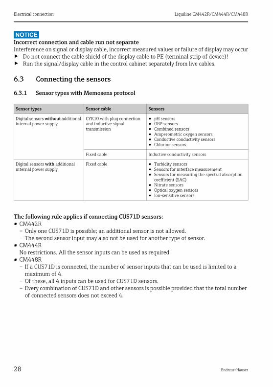
6.3 Connecting the sensors
6.3.1 Sensor types with Memosens protocol
The following rule applies if connecting CUS71D sensors:• CM442R
– Only one CUS71D is possible; an additional sensor is not allowed.– The second sensor input may also not be used for another type of sensor.
• CM444RNo restrictions. All the sensor inputs can be used as required.
• CM448R– If a CUS71D is connected, the number of sensor inputs that can be used is limited to a
maximum of 4.– Of these, all 4 inputs can be used for CUS71D sensors.– Every combination of CUS71D and other sensors is possible provided that the total number
of connected sensors does not exceed 4.
Sensor types Sensor cable Sensors
Digital sensors without additional internal power supply
CYK10 with plug connection and inductive signal transmission
• pH sensors• ORP sensors• Combined sensors• Amperometric oxygen sensors• Conductive conductivity sensors• Chlorine sensors
Fixed cable Inductive conductivity sensors
Digital sensors with additional internal power supply
Fixed cable • Turbidity sensors• Sensors for interface measurement• Sensors for measuring the spectral absorption
coefficient (SAC)• Nitrate sensors• Optical oxygen sensors• Ion-sensitive sensors
Liquiline CM442R/CM444R/CM448R Electrical connection
Endress+Hauser 29
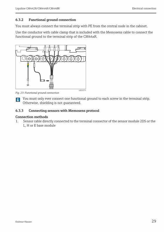
6.3.2 Functional ground connection
You must always connect the terminal strip with PE from the central node in the cabinet.
Use the conductor with cable clamp that is included with the Memosens cable to connect the functional ground to the terminal strip of the CM44xR.
You must only ever connect one functional ground to each screw in the terminal strip. Otherwise, shielding is not guaranteed.
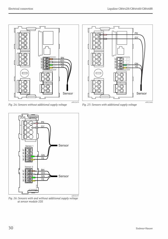
6.3.3 Connecting sensors with Memosens protocol
Connection methods1. Sensor cable directly connected to the terminal connector of the sensor module 2DS or the
L, H or E base module
a0020579
Fig. 23: Functional ground connection
Electrical connection Liquiline CM442R/CM444R/CM448R
30 Endress+Hauser
a0012459
Fig. 24: Sensors without additional supply voltagea0012460
Fig. 25: Sensors with additional supply voltage
a0016197
Fig. 26: Sensors with and without additional supply voltage at sensor module 2DS
Liquiline CM442R/CM444R/CM448R Electrical connection
Endress+Hauser 31
6.4 Connecting additional inputs, outputs or relays
WARNING!
Module not coveredNo shock protection. Danger of electric shock!‣ If you are modifying or extending your hardware, always fill the slots from left to right. Do
not leave any gaps.‣ If not all the slots are occupied, always insert one or more dummy modules into the slot to
the right of the last module until all the positions are filled (→ å 1, item 3). This ensures the unit is shock-protected.
‣ Always ensure shock protection is guaranteed particularly in the case of relay modules (2R, 4R, AOR).
The terminal strip (→ å 23) is used to connect cable shields. Any shields that are additionally needed must be connected to PE centrally in the cabinet via terminal blocks provided by the customer.
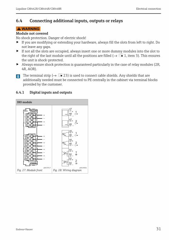
6.4.1 Digital inputs and outputs
DIO module
a0019917
Fig. 27: Module fronta0019836
Fig. 28: Wiring diagram

Electrical connection Liquiline CM442R/CM444R/CM448R
32 Endress+Hauser
6.4.2 Current inputs
6.4.3 Current outputs
Module 2AI
a0016184
Fig. 29: Module fronta0015761
Fig. 30: Wiring diagram
Module 2AO Module 4AO
a0016179
Fig. 31: Module fronta0015759
Fig. 32: Wiring diagrama0016178
Fig. 33: Module fronta0015760
Fig. 34: Wiring diagram
Liquiline CM442R/CM444R/CM448R Electrical connection
Endress+Hauser 33
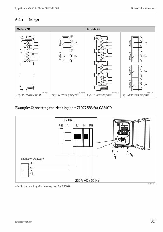
6.4.4 Relays
Example: Connecting the cleaning unit 71072583 for CAS40D
Module 2R Module 4R
a0016181
Fig. 35: Module fronta0015758
Fig. 36: Wiring diagrama0016182
Fig. 37: Module fronta0015757
Fig. 38: Wiring diagram
a0016195
Fig. 39: Connecting the cleaning unit for CAS40D

Electrical connection Liquiline CM442R/CM444R/CM448R
34 Endress+Hauser
Example: Connecting the injector cleaning unit Chemoclean CYR10
a0016194
Fig. 40: Connecting the injector cleaning unit CYR10
1 External power supply2 Cleaner to spray head3 Container with cleaner4 Motive water 2 to 12 bar (30 to 180 psi)5 Backflow valve (to be provided by the customer)

Liquiline CM442R/CM444R/CM448R Electrical connection
Endress+Hauser 35
6.5 Connecting digital communication
6.5.1 Module 485
a0016173
Fig. 41: Bus connections on module 485
* Optional to supply power to an external terminating resistor for bus termination
a0015762
Fig. 42: Wiring diagram for module 485
LEDs on front of module
LED Designation Color Description
RJ45 LNK/ACT GN • Off = Connection is not active• On = Connection is active• Flashing = Data transmission
RJ45 10/100 YE • Off = Transmission rate 10 MBit/s• On = Transmission rate 100 MBit/s
PWR Power GN Supply voltage is applied and module is initialized
BF Bus failure RD Bus failure
SF System failure RD System failure
COM Communication YE Sending or receiving Modbus message
T Bus termination YE • Off = No termination• On = Termination is used

Electrical connection Liquiline CM442R/CM444R/CM448R
36 Endress+Hauser
6.5.2 Bus termination
There are two ways to terminate the bus:1. Internal terminating resistor (via DIP switch on the module board)
‣ Using a suitable tool, such as a tweezers, set all 4 DIP switches to the "ON" position.
The internal terminating resistor is used.
a0016306
Fig. 44: Structure of the internal terminating resistor
2. External terminating resistor
Here, leave the DIP switches on the module board in the "OFF" position (factory setting).
DIP switches on front of module
DIP Factory setting Assignment
1-128 ON Bus address (--> "Commissioning/Communication")
OFF Write protection: "ON" = configuration not possible via the bus, only via local operation
Service OFF Only for service, not to be used by the operator
Fig. 43: DIP switches for internal terminating resistor
Liquiline CM442R/CM444R/CM448R Electrical connection
Endress+Hauser 37
‣ Connect the resistor to terminals 81 and 82 on the front of module 485 for 5-V power supply.
The external terminating resistor is used.
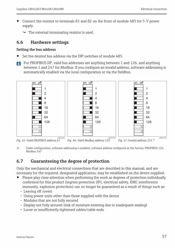
6.6 Hardware settingsSetting the bus address
‣ Set the desired bus address via the DIP switches of module 485.
For PROFIBUS DP, valid bus addresses are anything between 1 and 126, and anything between 1 and 247 for Modbus. If you configure an invalid address, software addressing is automatically enabled via the local configuration or via the fieldbus.
6.7 Guaranteeing the degree of protectionOnly the mechanical and electrical connections that are described in this manual, and are necessary for the required, designated application, may be established on the device supplied.‣ Please play close attention when performing the work as degrees of protection individually
confirmed for this product (ingress protection (IP), electrical safety, EMC interference immunity, explosion protection) can no longer be guaranteed as a result of things such as:
– Leaving off covers– Using power units other than those supplied with the device– Modules that are not fully secured– Display not fully secured (risk of moisture entering due to inadequate sealing)– Loose or insufficiently tightened cables/cable ends
a0016322
Fig. 45: Valid PROFIBUS address 67a0016323
Fig. 46: Valid Modbus address 195a0016324
Fig. 47: Invalid address 255 1)
1) Order configuration, software addressing is enabled, software address configured at the factory: PROFIBUS 126, Modbus 247
Electrical connection Liquiline CM442R/CM444R/CM448R
38 Endress+Hauser
6.8 Post-connection check
WARNING!
Wiring errorsIncorrect wiring puts the safety of people and the measuring point at risk. The manufacturer does not accept any responsibility for errors that result from failure to comply with the instructions in this manual.‣ Operate the device only if you can answer yes toall of the following questions.
Electrical connection• Are the mounted cables strain relieved?• Are the cables run without loops and cross-overs?• Are the signal lines correctly connected in accordance with the wiring diagram?• Are all plug-in terminals securely engaged?• Are all the connection wires securely positioned in the cable terminals?

Liquiline CM442R/CM444R/CM448R System integration
Endress+Hauser 39
7 System integration
7.1 Web server
7.1.1 Connection
‣ Connect the PC communication cable to the RJ45 port of module 485.
a0016228
Fig. 48: Ethernet connection
7.1.2 Creating the data connection
1. Start your PC.
2. First, set a manual IP address in the network connection settings of the operating system.
This address must be in the same subnetwork as the IP address of the device.
Example:
• IP address for the PC: 192.168.1.213
3. Start the Internet browser.
If you use a proxy server to connect to the Internet:
4. Disable the proxy (browser settings under "Connections/LAN settings").
5. Enter the IP address of your device in the address line.
The system takes a few moments to establish the connection and then the CM44 web server starts.
‣ Enter the following address(es) to download logbooks:
• 192.168.1.212/logbooks_csv.fhtml (for logbooks in CSV format)
• 192.168.1.212/logbooks_fdm.fhtml (for logbooks in FDM format)
System integration Liquiline CM442R/CM444R/CM448R
40 Endress+Hauser
Downloads in FDM format can be securely transmitted, saved and visualized with Endress+Hauser's "Field Data Manager Software".(--> www.products.endress.com/ms20)
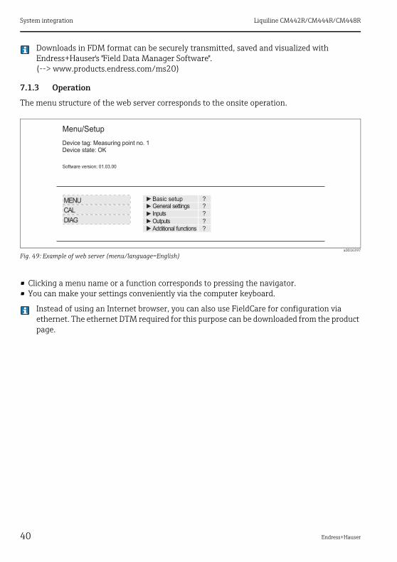
7.1.3 Operation
The menu structure of the web server corresponds to the onsite operation.
a0016397
Fig. 49: Example of web server (menu/language=English)
• Clicking a menu name or a function corresponds to pressing the navigator.• You can make your settings conveniently via the computer keyboard.
Instead of using an Internet browser, you can also use FieldCare for configuration via ethernet. The ethernet DTM required for this purpose can be downloaded from the product page.
Menu/Setup
Device tag: Measuring point no. 1Device state: OK
Software version: 01.03.00
Basic setupGeneral settings
Inputs
OutputsAdditional functions
??
?
?
?
MENU
CAL
DIAG

Liquiline CM442R/CM444R/CM448R System integration
Endress+Hauser 41
7.2 Service interfaceYou can connect the device to a computer via the service interface and configure it using "Fieldcare". Furthermore, configurations can also be saved, transferred and documented.
7.2.1 Connection
‣ Connect the service connector to the interface on the Liquiline base module and connect it to the Commubox.
‣ Via the USB port, connect the Commubox to the computer running the Fieldcare software.
a0014953
Fig. 50: Connection overview
7.2.2 Creating the data connection
1. Start Fieldcare.
2. Establish a connection to the Commubox. For this, select the ComDTM "CDI Communication FXA291"
3. Then select the DTM for CM442/CM444/CM448/CM442R/CM444R/CM448R and start the configuration.
You can now start online configuration via the DTM.Online configuration competes with onsite operation, i.e. each of the two options blocks the other one. On both sides it is possible to take away access from the other side.
A video showing an example of how to set up a connection to CM44x is available on the CD.
7.2.3 Operation
• In the DTM the menu structure corresponds to the onsite operation. The functions of the Liquiline soft keys are found in the main window on the left.
• Clicking a menu name or a function corresponds to pressing the navigator.• You can make your settings conveniently via the computer keyboard.• Via Fieldcare, you can save logbooks, make backups of configurations and transfer the
configurations to other devices.• You can also print out configurations or save them as PDFs.

System integration Liquiline CM442R/CM444R/CM448R
42 Endress+Hauser
7.3 Fieldbuses
7.3.1 HART
You can communicate using the HART protocol via current output 1.‣ Connect the HART modem or handheld to current output 1 (communication load 230 - 500
Ohm).‣ Establish the connection via your HART device.
All the information on HART communication is provided on the CD (--> BA00486C).
7.3.2 PROFIBUS DP
With the fieldbus module 485 and the appropriate device version, you can communicate via PROFIBUS DP.Connect the PROFIBUS data cable to the terminals of the fieldbus module as described → ä 35.
7.3.3 Modbus
With the fieldbus module 485 and the appropriate device version, you can communicate via Modbus RS485 or Modbus TCP.The RTU and ASCII protocols are available when connecting via Modbus RS485. You can switch to ASCII on the device.Connect the Modbus data cable to the terminals of the fieldbus module (RS 485) or to the RJ45 (TCP) port as described (→ ä 35).
7.3.4 EtherNet/IP
With the fieldbus module 485 and the appropriate device version, you can communicate via EtherNet/IP.Connect the EtherNet/IP data cable to the RJ45 socket of the fieldbus module as described.

Liquiline CM442R/CM444R/CM448R Operation options
Endress+Hauser 43
8 Operation options
8.1 Overview
8.1.1 Display and operating elements (only with optional display)
8.1.2 Display
a0020580
Fig. 51: Overview of operation
1 Display (lights up red in the event of an error)2 LED3 Navigator (jog/shuttle and press/hold function)4 Soft keys (function depends on the menu)
a0012697-en
Fig. 52: Display (example)
1234
Menu path and/or device designationStatus displayHelp if availableAssignment of the soft keys
Operation options Liquiline CM442R/CM444R/CM448R
44 Endress+Hauser
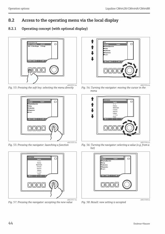
8.2 Access to the operating menu via the local display
8.2.1 Operating concept (with optional display)
a0013353-en
Fig. 53: Pressing the soft key: selecting the menu directlya0013354-en
Fig. 54: Turning the navigator: moving the cursor in the menu
a0013355-en
Fig. 55: Pressing the navigator: launching a functiona0013356-en
Fig. 56: Turning the navigator: selecting a value (e.g. from a list)
a0013357-en
Fig. 57: Pressing the navigator: accepting the new valuea0013358-en
Fig. 58: Result: new setting is accepted
Liquiline CM442R/CM444R/CM448R Operation options
Endress+Hauser 45
8.2.2 Locking or unlocking operating keys
Locking operating keys
1. Press the navigator for longer than 2 s.
A context menu for locking the operating keys is displayed.
You have the choice of locking the keys with or without password protection. "With password" means that you can only unlock the keys again by entering the correct password. You can set this password here: Menu/Setup/General settings/Extended setup/Data management/Change lock password.
2. Choose whether you want to lock with or without a password.
The keys are locked. No more entries can be made. In the soft key bar you can see the symbol .
The password is 0000 when the device is delivered from the factory. Make sure to note down any new password as otherwise you will not be able to unlock the keypad yourself.
Unlocking operating keys
1. Press the navigator for longer than 2 s.
A context menu for unlocking the operating keys is displayed.
2. Select "Key unlock".
The keys are unlocked immediately if you did not choose to lock with a password. Otherwise you are asked to enter your password.
3. Only if keypad is password-protected: enter the right password.
The keys are unlocked. It is possible to access the entire onsite operation again. The symbol is no longer visible on the screen.
8.3 Configuration options
8.3.1 Display only
• You can only read the values but cannot change them.• Typical read-only values are: sensor data and system information• Example: Menu/Setup/Inputs/../Sensor type
8.3.2 Picklists
• You receive a list of options.• You select one of the options.• Example: Menu/Setup/General settings/Temperature unit

Operation options Liquiline CM442R/CM444R/CM448R
46 Endress+Hauser
8.3.3 Numerical values
• You are changing a variable.• The maximum and minimum values for this variable are shown in the editor.• Set a value within this range.• Example: Menu/Display/Operation/Contrast
8.3.4 Actions
• You trigger an action with the appropriate function.• You know that the item in question is an action if it is preceded by the following symbol:
8.3.5 Free text
• You are assigning an individual designation.• Enter a text. You can use the characters in the editor for this purpose (upper-case and
lower-case letters, numbers and special characters).• Using the soft keys, you can:
– Cancel your entries without saving the data ( )– Delete the character in front of the cursor ( )– Move the cursor back one position ( )– Finish your entries and save ( ).

Liquiline CM442R/CM444R/CM448R Operation options
Endress+Hauser 47
8.3.6 Tables
• Tables are needed to map mathematical functions.• You edit a table by navigating through rows and columns with the navigator and changing the
values of the cells.• You only edit the numerical values. The controller automatically takes care of the engineering
units.• You can add rows to the table (soft key "INSERT") or delete them (soft key "DEL").• Afterwards, you save the table (soft key "SAVE").• You can also cancel your entries any time via the soft key .• Example: Menu/Setup/Inputs/pH/Medium comp.
Commissioning Liquiline CM442R/CM444R/CM448R
48 Endress+Hauser
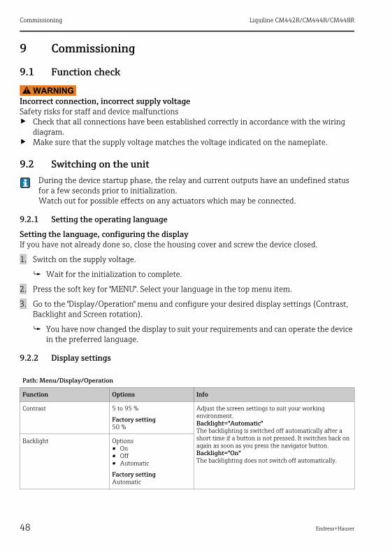
9 Commissioning
9.1 Function check
WARNING!
Incorrect connection, incorrect supply voltageSafety risks for staff and device malfunctions‣ Check that all connections have been established correctly in accordance with the wiring
diagram.‣ Make sure that the supply voltage matches the voltage indicated on the nameplate.
9.2 Switching on the unitDuring the device startup phase, the relay and current outputs have an undefined status for a few seconds prior to initialization.Watch out for possible effects on any actuators which may be connected.
9.2.1 Setting the operating language
Setting the language, configuring the displayIf you have not already done so, close the housing cover and screw the device closed.
1. Switch on the supply voltage.
Wait for the initialization to complete.
2. Press the soft key for "MENU". Select your language in the top menu item.
3. Go to the "Display/Operation" menu and configure your desired display settings (Contrast, Backlight and Screen rotation).
You have now changed the display to suit your requirements and can operate the device in the preferred language.
9.2.2 Display settings
Path: Menu/Display/Operation
Function Options Info
Contrast 5 to 95 %
Factory setting50 %
Adjust the screen settings to suit your working environment.Backlight="Automatic"The backlighting is switched off automatically after a short time if a button is not pressed. It switches back on again as soon as you press the navigator button.Backlight="On"The backlighting does not switch off automatically.
Backlight Options• On• Off• Automatic
Factory settingAutomatic

Liquiline CM442R/CM444R/CM448R Commissioning
Endress+Hauser 49
Screen rotation Options• Manual• Automatic
Factory settingManual
If "Automatic" is selected, the single-channel measured value display switches from one channel to the next every second.
User definable screens
Meas. screen 1to
Meas. screen 6
You can create 6 measuring screens of your own and give them a name.As the functions are the same for all 6 measuring screens, only one measuring screen is described below.
Meas. screen Options• Off• On
Factory settingOff
Once you have defined your own measuring screen, you can switch it on here. You can find the new screen under "User definable screens" in the "All measured values" measuring mode.
Label Customized text, 20 characters
Name of the measuring screenAppears in the status bar of the display.
Number of lines 1 to 8
Factory setting1
Specify the number of measured values displayed.
Line 1to
Line 8
As the following functions are the same for all the lines, they are only described once.
Signal type Options• Source of data• Output
Factory settingSource of data
Select a source of data or an output as the signal type.
Source of data
Signal type= "Source of data"
Options• None• Sensor inputs• Controller• Current inputs• Fieldbus signals• Mathematical functions
Factory settingNone
Select a data source. You can choose from connected sensors, available controllers, current inputs, fieldbus signals and mathematical functions.
Output
Signal type= "Output"
Options• None• Binary outputs• Current outputs• Relays
Factory settingNone
Select an output. You can choose from binary outputs, current outputs and relays.
Path: Menu/Display/Operation
Function Options Info

Commissioning Liquiline CM442R/CM444R/CM448R
50 Endress+Hauser
9.3 Basic setupMaking basic settings
1. Go to the "Setup/Basic setup" menu.
Make the following settings:
2. Device tag: Give your device any name of your choice (max. 32 characters).
3. Set date: Correct the set date if necessary.
4. Set time: Correct the set time if necessary.
For quick commissioning, you can ignore the additional settings for outputs , relays etc. You can make these settings later in the specific menus.
5. Return to the measuring mode, by pressing and holding the soft key for "ESC" for at least one second.
Your controller now works with your general settings. The sensors connected use the factory settings of the sensor type in question and the individual calibration settings that were last saved.
If you want to configure your most important input and output parameters already in the "Basic setup", proceed as follows:‣ Configure the current outputs, relays, limit contactors, controllers, device diagnostics and
cleaning cycles with the submenus which follow the time setting.
Measured value Options• Depends on the source of
data or output
Factory settingNone
You can display different measured values depending on the source of data or output.
Label Customized text, 20 characters
User-defined name for the parameter to be displayed
Set label to "%0V"1) Action If you perform this action you accept the parameter name that is automatically suggested.Your own parameter name ("Label") is lost!
1) "%0V" here stands for text that depends on the context. This text is generated automatically by the software and inserted in place of %0V. In the simplest situations, the generated text could be the name of the measuring channel, for example.
Path: Menu/Display/Operation
Function Options Info

Liquiline CM442R/CM444R/CM448R Operation
Endress+Hauser 51
10 Operation
10.1 Display
10.1.1 Soft keys in the measurement mode
On the bottom row of the display you can find four soft keys in the measuring screens:• "MENU", "CAL" and "DIAG" take you directly to the particular software menu.• With "HOLD" you can activate an immediate, general hold for sensors. This interrupts any
sensor cleaning programs that are currently running. However, you can also start manual sensor cleaning when a hold is active.
10.1.2 Measuring mode
There are various display modes:(Press the navigator button to change the mode)1. Overview of all the inputs and outputs2. Main measured value of an input or output or the status of a relay3. Main and secondary measured value of a sensor input4. All measured values of a sensor input5. User-defined measuring screens
You configure the type and number of values you want to display. You can choose from all the measured values of physical and "virtual" sensors (calculated using mathematical functions) and output parameters.
In modes 2-4, you can switch between channels by turning the navigator.
Sensor type Main value Main / secondary measured value
All values
pH, glass pH value pH value, temperature Main value, Raw value, Temperature, Glass Impedance
Combined sensor pH and ORP
pH value or ORP or rH value pH value or ORP or rH value, temperature
Main value, Raw value, Temperature, Glass Impedance
pH, ISFET pH value pH value, temperature Main value, Raw value, Temperature
ORP ORP ORP, temperature Main value, Raw value, Offset:, Temperature
Conductivity, measured inductively
Conductivity Conductivity, temperature Main value, Raw value, Temperature
Conductivity, measured conductively
Conductivity Conductivity, temperature Main value, Raw value, Temperature
Oxygen, optical and amperometric
Dissolved oxygen Dissolved oxygen, temperature
Partial pressure, Saturation, Concentration, Temperature

Operation Liquiline CM442R/CM444R/CM448R
52 Endress+Hauser
10.1.3 Device status
Icons on the display alert you to special device states.
Chlorine, amperometric
Chlorine Chlorine, temperature Main value, Raw value, Temperature
Nitrate Nitrate Nitrate, temperature Main value, Raw value, Temperature
Spectral absorption coefficient (SAC)
SAC SAC, temperature Main value, Raw value, Temperature
Sludge level Turbidity Turbidity, temperature Main value, Raw value, Temperature
Ammonium, ion-sensitive
Ammonium Ammonium, temperature Main value, Raw value, Temperature
Nitrate, ion-sensitive
Nitrate Nitrate, temperature Main value, Raw value, Temperature
Potassium, ion-sensitive
Potassium Potassium, temperature Main value, Raw value, Temperature
Interface measurement
UIS UIS UIS, turbidityalso: graphic display
Icon Location Description
Title bar Diagnostic message "Failure"
Title bar Diagnostic message "Maintenance request"
Title bar Diagnostic message "Check"
Title bar Diagnostic message "Out of specification"
Title bar Fieldbus or TCP/IP communication active
Title bar Hold active
At measured value Hold for the actuator (current output, limit contactor etc.) is active
At measured value1) An offset has been added to the measured value
At measured value Measured value in "Bad" or "Alarm" state
At measured value Automatic temperature compensation active
At measured value Manual temperature compensation active
Title bar Simulation mode active or Memocheck SIM connected
Sensor type Main value Main / secondary measured value
All values

Liquiline CM442R/CM444R/CM448R Operation
Endress+Hauser 53
If two or more diagnostics messages occur simultaneously, only the icon for the message with the highest priority is shown on the display (for the order of priority according to NAMUR, see the "Changing diagnostic information" section).
10.1.4 Assignment views
Assignment views, e.g. Channel assignment view, appear as the last function in many sections of the menu.You can use this function to see which actuators or functions are connected to an or a sensor channel.The assignments appear in hierarchical order.
At measured value The measured value is influenced by a simulated value
At measured value The displayed measured value is simulated
1) Only pH or ORP measurement
Icon Location Description

Operation Liquiline CM442R/CM444R/CM448R
54 Endress+Hauser
10.2 General settings
10.2.1 Basic settings
10.2.2 Date and time
Path: Menu/Setup/General settings
Function Options Info
Device tag Customized text, 32 characters
Select any name for your controller. Use the TAG name for example.
Temperature unit Options• °C• °F• K
Factory setting°C
Current output range Options• 0 to 20 mA• 4 to 20 mA
Factory setting4 to 20 mA
In accordance with Namur NE43, the linear range is from 3.8 to 20.5 mA (Current output range="4 to 20 mA") or from 0 to 20.5 mA (Current output range="0 to 20 mA"). If the range is exceeded or undershot, the current value stops at the range limit and a diagnostics message (460 or 461) is output.
Error current 0.0 to 23.0 mA
Factory setting21.5 mA
The function meets NAMUR NE43.Set the current value that should be output at the current outputs in the event of an error.
The value for "Error current" should be outside the measuring range. If you decided that your Current output range = "0 to 20 mA", you should set an error current between 20.1 and 23 mA. If the Current output range = "4 to 20 mA" you could also define a value < 4 mA as the error current.The device allows an error current within the measuring range. In such instances pay attention to possible affects this may have on your process.
Alarm delay 0 to 9999 s
Factory setting0 s
The system only displays the errors that are present longer than the set delay time. This makes it possible to suppress messages that only occur briefly and are caused by normal process-specific fluctuations.
Device Hold Options• Disabled• Enabled
Factory settingDisabled
You can enable an immediate, general hold here. The function acts in the same way as the "HOLD" soft key in the measuring menus.
Path: Menu/Setup/General settings/Date/Time
Function Options Info
Set date Depends on the format Editing mode:Day (two-digit): 01 to 31Month (two-digit): 01 to 12Year (four-digit): 1970 to 2106

Liquiline CM442R/CM444R/CM448R Operation
Endress+Hauser 55
10.2.3 Automatic hold
Set time Depends on the format Editing mode:hh (hour): 00 to 23 / 0 am to 12 pmmm (minutes): 00 to 59ss (seconds): 00 to 59
Extended setup
Date format Options• DD.MM.YYYY• YYYY-MM-DD• MM-DD-YYYY
Factory settingDD.MM.YYYY
Decide which date format you want to use.
Time format Options• HH:MM am (12h)• HH:MM (24h)• HH:MM:SS (24h)
Factory settingHH:MM:SS (24h)
Decide whether you want to use the 12-hour or 24-hour clock. Seconds can also be displayed with the latter version.
Time zone Options• None• Choice of 35 time zones
Factory settingNone
If no time zone is selected, then Greenwich Mean Time is used (London).
DST Options• Off• Europe• USA• Manual
Factory settingOff
The controller adapts the summertime/normal time changeover automatically if you choose European or American daylight saving time.Manual means that you can specify the start and end of daylight saving time yourself. Here, two additional submenus are displayed in which you specify the changeover date and time.
Path: Menu/Setup/General settings/Automatic hold
Function Options Info
Device specific hold
Setup menu Options• Disabled• Enabled
Factory settingDisabled
Decide whether a hold should be output at the current output when the particular menu is opened.
Diagnostics menu
Calibration active Factory settingEnabled
Path: Menu/Setup/General settings/Date/Time
Function Options Info

Operation Liquiline CM442R/CM444R/CM448R
56 Endress+Hauser
If a device-specific hold is activated, any cleaning previously started is interrupted. When a hold is active you can only start manual cleaning.
10.2.4 Logbooks
Logbooks record the following events:• Calibration/adjustment events• Operator events• Diagnostic events
Here you define how the logbooks should store the data.In addition, you can also define individual data logbooks . Assign the logbook name and select the measured value to be recorded. You can set the scan time (Scan time) individually for every data logbook.Further information on the logbooks → ä 121.
Hold release time 0 to 600 s
Factory setting0 s
The hold is maintained for the duration of the delay time when you switch to the measuring mode.
Path: Menu/Setup/General settings/Logbooks
Function Options Info
Logbook ident Free text Part of the file name when exporting a logbook.
Event logbook Options• Off• Ring buffer• Fill up buffer
Factory settingRing buffer
All diagnostic messages are recorded
Ring bufferIf the memory is full, the most recent entry automatically overwrites the oldest entry.Fill up bufferIf the memory is full, there is an overflow, i.e. no new values can be saved. The controller displays a corresponding diagnostic message. The memory then has to be cleared manually.
Overflow warnings
Event logbook="Fill up buffer"
Calibration logbook Options• Off• On
Factory settingOff
Decide whether you want to receive a diagnostic message from the controller in the event of fill-up buffer overrun of the logbook in question.Diagnostic logbook
Configuration logbook
Source of data Read only The assigned measuring channel is displayed
Measuring parameter Read only Plain-text information on the parameter that is being recorded
Path: Menu/Setup/General settings/Automatic hold
Function Options Info

Liquiline CM442R/CM444R/CM448R Operation
Endress+Hauser 57
Main value Read only Information on the main value and the unit.
Unit Read only
Data logbooks
New You can create a maximum of 8 data logbooks.
Logbook name Customized text, 20 characters
Source of data Options• Sensor inputs• Controller• Current inputs• Fieldbus signals• Mathematical functions
Factory settingNone
Select a data source for the logbook entries. You can choose from connected sensors, available controllers, current inputs, fieldbus signals and mathematical functions.
Measured value Options• depend onSource of data
Factory settingNone
You can record different measured values depending on the data source.
Scan time 00:00:01 to 01:00:00
Factory setting00:01:00
Minimum interval between two entriesFormat: HH:MM:SS
Data logbook Options• Off• Ring buffer• Fill up buffer
Factory settingOff
Ring bufferIf the memory is full, the most recent entry automatically overwrites the oldest entry.Fill up bufferIf the memory is full, there is an overflow, i.e. no new values can be saved. The controller displays a corresponding diagnostic message. The memory then has to be cleared manually.
Add another logbook Action Only if you want to create another data logbook immediately.You add a new data logbook at a later date using New.
Finished Action This allows you to exit the menu New.
Start/stop simultaneously
Action Appears if you have created more than one data logbook. With one mouse click, you can start or stop recording all the data logbooks.
"Logbook name" The name of this submenu is based on the name of the logbook and only appears once you have created a logbook.
This menu appears several times if you have several data logbooks.
Source of data Read only This is for information purposes only. If you want to record another value, delete this logbook and create a new data logbook.Measured value
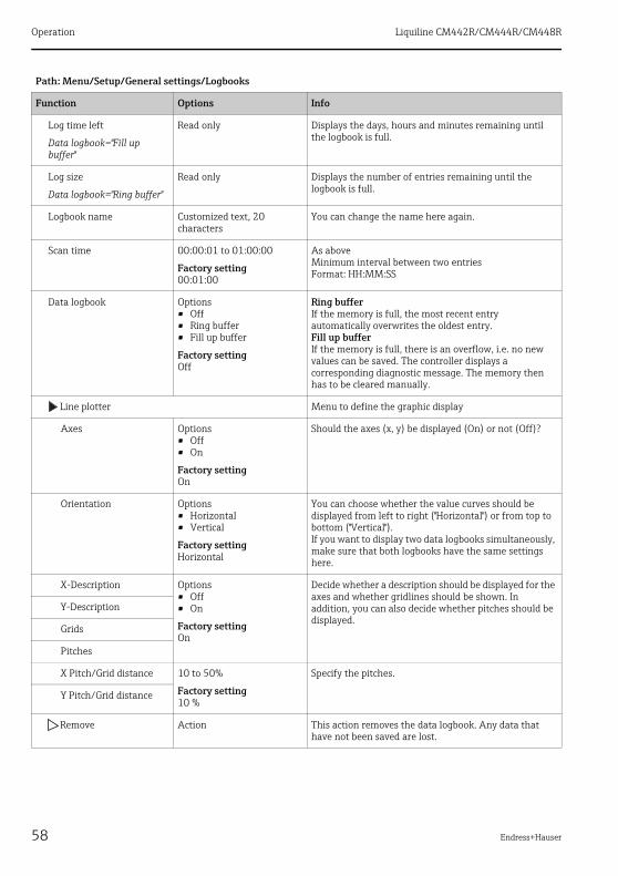
Path: Menu/Setup/General settings/Logbooks
Function Options Info
Operation Liquiline CM442R/CM444R/CM448R
58 Endress+Hauser
Log time left
Data logbook="Fill up buffer"
Read only Displays the days, hours and minutes remaining until the logbook is full.
Log size
Data logbook="Ring buffer"
Read only Displays the number of entries remaining until the logbook is full.
Logbook name Customized text, 20 characters
You can change the name here again.
Scan time 00:00:01 to 01:00:00
Factory setting00:01:00
As aboveMinimum interval between two entriesFormat: HH:MM:SS
Data logbook Options• Off• Ring buffer• Fill up buffer
Factory settingOff
Ring bufferIf the memory is full, the most recent entry automatically overwrites the oldest entry.Fill up bufferIf the memory is full, there is an overflow, i.e. no new values can be saved. The controller displays a corresponding diagnostic message. The memory then has to be cleared manually.
Line plotter Menu to define the graphic display
Axes Options• Off• On
Factory settingOn
Should the axes (x, y) be displayed (On) or not (Off)?
Orientation Options• Horizontal• Vertical
Factory settingHorizontal
You can choose whether the value curves should be displayed from left to right ("Horizontal") or from top to bottom ("Vertical").If you want to display two data logbooks simultaneously, make sure that both logbooks have the same settings here.
X-Description Options• Off• On
Factory settingOn
Decide whether a description should be displayed for the axes and whether gridlines should be shown. In addition, you can also decide whether pitches should be displayed.
Y-Description
Grids
Pitches
X Pitch/Grid distance 10 to 50%
Factory setting10 %
Specify the pitches.
Y Pitch/Grid distance
Remove Action This action removes the data logbook. Any data that have not been saved are lost.
Path: Menu/Setup/General settings/Logbooks
Function Options Info
Liquiline CM442R/CM444R/CM448R Operation
Endress+Hauser 59
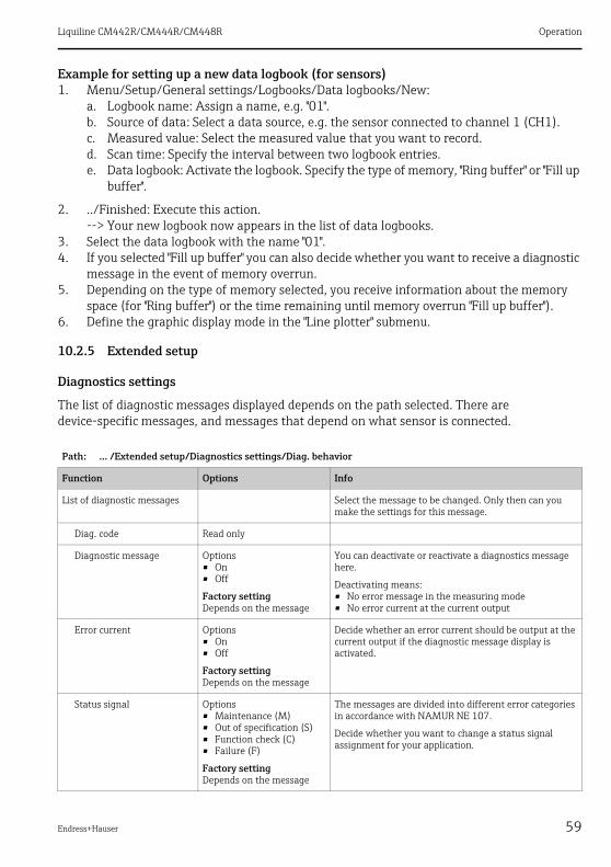
Example for setting up a new data logbook (for sensors)1. Menu/Setup/General settings/Logbooks/Data logbooks/New:
a. Logbook name: Assign a name, e.g. "01".b. Source of data: Select a data source, e.g. the sensor connected to channel 1 (CH1).c. Measured value: Select the measured value that you want to record.d. Scan time: Specify the interval between two logbook entries.e. Data logbook: Activate the logbook. Specify the type of memory, "Ring buffer" or "Fill up
buffer".
2. ../Finished: Execute this action.--> Your new logbook now appears in the list of data logbooks.
3. Select the data logbook with the name "01".4. If you selected "Fill up buffer" you can also decide whether you want to receive a diagnostic
message in the event of memory overrun.5. Depending on the type of memory selected, you receive information about the memory
space (for "Ring buffer") or the time remaining until memory overrun "Fill up buffer").6. Define the graphic display mode in the "Line plotter" submenu.
10.2.5 Extended setup
Diagnostics settings
The list of diagnostic messages displayed depends on the path selected. There are device-specific messages, and messages that depend on what sensor is connected.
Path: ... /Extended setup/Diagnostics settings/Diag. behavior
Function Options Info
List of diagnostic messages Select the message to be changed. Only then can you make the settings for this message.
Diag. code Read only
Diagnostic message Options• On• Off
Factory settingDepends on the message
You can deactivate or reactivate a diagnostics message here.
Deactivating means:• No error message in the measuring mode• No error current at the current output
Error current Options• On• Off
Factory settingDepends on the message
Decide whether an error current should be output at the current output if the diagnostic message display is activated.
Status signal Options• Maintenance (M)• Out of specification (S)• Function check (C)• Failure (F)
Factory settingDepends on the message
The messages are divided into different error categories in accordance with NAMUR NE 107.
Decide whether you want to change a status signal assignment for your application.

Operation Liquiline CM442R/CM444R/CM448R
60 Endress+Hauser
HART bus address
If Multidrop is active (Bus address > 0), the current at current output 1 is fixed at 4 mA.Here, it does not matter what function has been assigned to the output (measured value/controller etc.). Current simulation is no longer possible.
If you reset the device to the factory settings (Diagnostics/Systemtest/Reset/Factory default), the bus address is not reset. Your setting is retained.
PROFIBUS DP
Diag. output Options• None
Factory settingNone
Before you can assign the message to an output, you must first configure a relay output to "Diagnostics" (Menu/Setup/Outputs, assign the "Diagnostics" function and set the Operating mode to "as assigned").
Cleaning program (for sensors)
Options• None• Cleaning 1• Cleaning 2• Cleaning 3• Cleaning 4
Factory settingNone
Decide whether the diagnostic message should trigger a cleaning program.You can define the cleaning programs under:Menu/Setup/Additional functions/Cleaning.
Detail information Read only Here you can find more information on the diagnostic message and instructions on how to resolve the problem.
Path: Menu/Setup/General settings/Extended setup/HART
Function Options Info
Bus address 0 to 63
Factory setting0
You can change the device address to integrate several HART devices in a single network (Multidrop mode).
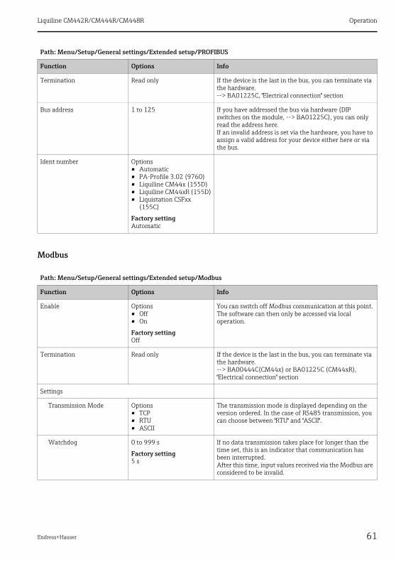
Path: Menu/Setup/General settings/Extended setup/PROFIBUS
Function Options Info
Enable Options• Off• On
Factory settingOff
You can switch off PROFIBUS communication at this point. The software can then only be accessed via local operation.
Path: ... /Extended setup/Diagnostics settings/Diag. behavior
Function Options Info
Liquiline CM442R/CM444R/CM448R Operation
Endress+Hauser 61
Modbus
Termination Read only If the device is the last in the bus, you can terminate via the hardware.--> BA01225C, "Electrical connection" section
Bus address 1 to 125 If you have addressed the bus via hardware (DIP switches on the module, --> BA01225C), you can only read the address here.If an invalid address is set via the hardware, you have to assign a valid address for your device either here or via the bus.
Ident number Options• Automatic• PA-Profile 3.02 (9760)• Liquiline CM44x (155D)• Liquiline CM44xR (155D)• Liquistation CSFxx
(155C)
Factory settingAutomatic
Path: Menu/Setup/General settings/Extended setup/Modbus
Function Options Info
Enable Options• Off• On
Factory settingOff
You can switch off Modbus communication at this point. The software can then only be accessed via local operation.
Termination Read only If the device is the last in the bus, you can terminate via the hardware.--> BA00444C(CM44x) or BA01225C (CM44xR), "Electrical connection" section
Settings
Transmission Mode Options• TCP• RTU• ASCII
The transmission mode is displayed depending on the version ordered. In the case of RS485 transmission, you can choose between "RTU" and "ASCII".
Watchdog 0 to 999 s
Factory setting5 s
If no data transmission takes place for longer than the time set, this is an indicator that communication has been interrupted.After this time, input values received via the Modbus are considered to be invalid.
Path: Menu/Setup/General settings/Extended setup/PROFIBUS
Function Options Info

Operation Liquiline CM442R/CM444R/CM448R
62 Endress+Hauser
EtherNet/IP
EtherNet Industrial Protocol is an open fieldbus standard of the Open DeviceNet Vendor Association (ODVA). --> www.odva.org
Path: Menu/Setup/General settings/Extended setup/Ethernet
Function Options Info
Enable Options• Off• On
Factory settingOn
You can switch ethernet communication on and off at this point.
Settings
Link settings Options• Auto negotiation• 10MBps Half duplex• 10MBps Full duplex• 100MBps Half duplex• 100MBps Full duplex
Factory settingAuto negotiation
Transmission methods of the communication channels• Full duplex:
Data can be transmitted simultaneously in both directions.
• Half-duplex:Data can only be transmitted alternately in both directions, i.e. not at the same time.
Source: Wikipedia
DHCP Options• Off• On
Factory settingOff
The Dynamic Host Configuration Protocol (DHCP) makes it possible to assign the network configuration to clients via a server. With DHCP, it is possible to automatically integrate the device into an existing network without the need for manual configuration. Normally, the client need only be configured for automatic retrieval of the IP addresses. During startup, the IP address, the netmask and the gateway are retrieved from a DHCP server.
IP-Address xxx.xxx.xxx.xxx
Factory setting192.168.1.212
An IP address is an address in computer networks which are based on the Internet protocol (IP).
Netmask xxx.xxx.xxx.xxx
Factory setting255.255.255.0
On the basis of the IP address of a device, the netmask specifies which IP addresses this device searches for in its own network and which addresses it could access in other networks via a router. It therefore divides the IP address into a network part (network prefix) and a device part. The network part must be identical for all devices in the individual network, and the device part must be different for every device within the network.
Gateway x.x.x.x
Factory setting0.0.0.0
A gateway (protocol converter) enables communication between networks that are based on completely different protocols.
MAC-Address Read only The MAC address (Media Access Control address) is the hardware address of every individual network adapter which is used to uniquely identify the device in a computer network.
EtherNetIP Port 44818 Read only A port is a part of an address which assigns data segments to a network protocol.
Liquiline CM442R/CM444R/CM448R Operation
Endress+Hauser 63
Web server
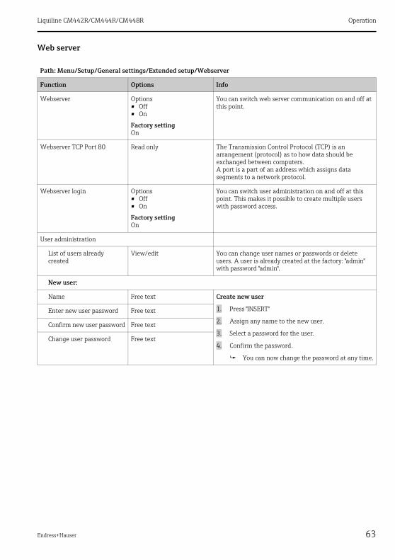
Path: Menu/Setup/General settings/Extended setup/Webserver
Function Options Info
Webserver Options• Off• On
Factory settingOn
You can switch web server communication on and off at this point.
Webserver TCP Port 80 Read only The Transmission Control Protocol (TCP) is an arrangement (protocol) as to how data should be exchanged between computers.A port is a part of an address which assigns data segments to a network protocol.
Webserver login Options• Off• On
Factory settingOn
You can switch user administration on and off at this point. This makes it possible to create multiple users with password access.
User administration
List of users already created
View/edit You can change user names or passwords or delete users. A user is already created at the factory: "admin" with password "admin".
New user:
Name Free text Create new user
1. Press "INSERT"
2. Assign any name to the new user.
3. Select a password for the user.
4. Confirm the password.
You can now change the password at any time.
Enter new user password Free text
Confirm new user password Free text
Change user password Free text

Operation Liquiline CM442R/CM444R/CM448R
64 Endress+Hauser
Data management
Firmware update
Please contact your local sales office for information on firmware updates available for your controller and its compatibility with earlier versions.Your current firmware version can be found at: Menu/Diagnostics/System information/Software version.
To install a firmware update, you must have the update available on an SD card.
1. Insert the SD card into the controller card reader.
2. Go to: Menu/Setup/General settings/Extended setup/Data management/Firmware update.
The update files on the SD card are displayed.
3. Select the desired update and select yes when the following question is displayed: The current firmware will be overwritten. After this the device will reboot. Do you want to proceed?
The firmware is loaded and the device is then started with the new firmware.
Saving the setup
Saving the setup gives you the following advantages:• Quick and easy to restore a setup following a firmware update• Copying settings for other devices• Quick and easy switching between various setups, e.g. for different user groups or for
recurring sensor type change• Restoring a tried-and-tested setup, e.g. if you have changed a lot of settings and no longer
know what the original settings were
1. Insert the SD card into the controller card reader.
2. Go to: Menu/Setup/General settings/Extended setup/Data management/canada.
3. Assign a file name (Name).
4. Then select "Save".
5. If you have already assigned the file name, you will be asked whether you want to overwrite the existing setup.
6. Select "OK" to confirm, or cancel the action and give the file a new name.
Your setup is stored on the SD card and you can upload it quickly to the device at a later date.

Liquiline CM442R/CM444R/CM448R Operation
Endress+Hauser 65
Loading the setup
You can load a setup you have saved quickly and easilyWhen you load a setup, the current configuration is overwritten. Note that cleaning and controller programs could be active. Do you want to continue anyway?
1. Insert the SD card into the controller card reader.
2. Go to: Menu/Setup/General settings/Extended setup/Data management/Load setup.
A list of all the setups on the SD card is displayed.
3. Select the desired setup.
The device then displays the following message:The current parameters will be overwritten and the device will reboot. Warning: Please note that cleaning and controller programs can be active. Do you want to proceed?
4. Select "OK" to confirm or cancel the action.
The desired setup is restored after restarting the device.
Exporting the setup
Exporting the setup gives you the following advantages:• Export in XML format with a stylesheet for formatted display in an XML-compatible
application such as Microsoft Internet Explorer• Importing the data (drag and drop the XML file into a browser window)
1. Insert the SD card into the controller card reader.
2. Go to: Menu/Setup/General settings/Extended setup/Data management/Export setup.
3. Assign a file name (Name).
4. Then select "Export".
5. If you have already assigned the file name, you will be asked whether you want to overwrite the existing setup.
6. Select "OK" to confirm, or cancel the action and give the file a new name.
Your setup is saved on the SD card in a folder named "Device".
You cannot upload the exported setup to the device again. You must use the "Save setup" function for this purpose. This is the only way you can save a setup to an SD card and reload it later on or upload it to other devices.
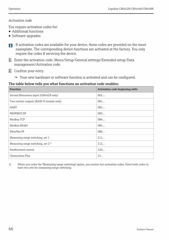
Operation Liquiline CM442R/CM444R/CM448R
66 Endress+Hauser
Activation code
You require activation codes for:• Additional functions• Software upgrades
If activation codes are available for your device, these codes are provided on the inner nameplate. The corresponding device functions are activated at the factory. You only require the codes if servicing the device.
1. Enter the activation code: Menu/Setup/General settings/Extended setup/Data management/Activation code.
2. Confirm your entry.
Your new hardware or software function is activated and can be configured.
The table below tells you what functions an activation code enables:Function Activation code beginning with:
Second Memosens input (CM442R only) 062...
Two current outputs (BASE-E module only) 081...
HART 0B1...
PROFIBUS DP 0B3...
Modbus TCP 0B4...
Modbus RS485 0B5...
EtherNet/IP 0B6...
Measuring range switching, set 1 211...
Measuring range switching, set 21)
1) When you order the "Measuring range switching" option, you receive two activation codes. Enter both codes to have two sets for measuring range switching.
212...
Feedforward control 220...
Chemoclean Plus 25...
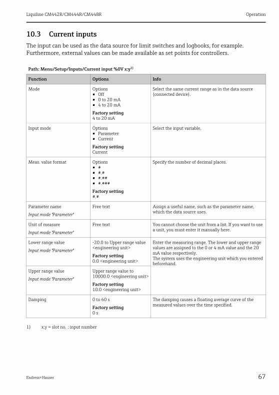
Liquiline CM442R/CM444R/CM448R Operation
Endress+Hauser 67
10.3 Current inputsThe input can be used as the data source for limit switches and logbooks, for example. Furthermore, external values can be made available as set points for controllers.
Path: Menu/Setup/Inputs/Current input %0V x:y1)
1) x:y = slot no. : input number
Function Options Info
Mode Options• Off• 0 to 20 mA• 4 to 20 mA
Factory setting4 to 20 mA
Select the same current range as in the data source (connected device).
Input mode Options• Parameter• Current
Factory settingCurrent
Select the input variable.
Meas. value format Options• #• #.#• #.##• #.###
Factory setting#.#
Specify the number of decimal places.
Parameter name
Input mode "Parameter"
Free text Assign a useful name, such as the parameter name, which the data source uses.
Unit of measure
Input mode "Parameter"
Free text You cannot choose the unit from a list. If you want to use a unit, you must enter it manually here.
Lower range value
Input mode "Parameter"
-20.0 to Upper range value <engineering unit>
Factory setting0.0 <engineering unit>
Enter the measuring range. The lower and upper range values are assigned to the 0 or 4 mA value and the 20 mA value respectively.The system uses the engineering unit which you entered beforehand.
Upper range value
Input mode "Parameter"
Upper range value to 10000.0 <engineering unit>
Factory setting10.0 <engineering unit>
Damping 0 to 60 s
Factory setting0 s
The damping causes a floating average curve of the measured values over the time specified.
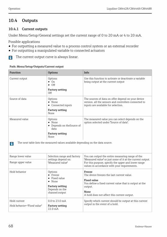
Operation Liquiline CM442R/CM444R/CM448R
68 Endress+Hauser
10.4 Outputs
10.4.1 Current outputs
Under Menu/Setup/General settings set the current range of 0 to 20 mA or 4 to 20 mA.
Possible applications• For outputting a measured value to a process control system or an external recorder• For outputting a manipulated variable to connected actuators
The current output curve is always linear.
Path: Menu/Setup/Outputs/Current output
Function Options Info
Current output Options• On• Off
Factory settingOff
Use this function to activate or deactivate a variable being output at the current output
Source of data Options• None• Connected inputs
Factory settingNone
The sources of data on offer depend on your device version. all the sensors and controllers connected to inputs are available for selection.
Measured value Options• None• Depends on theSource of
data
Factory settingNone
The measured value you can select depends on the option selected under "Source of data".
The next table lists the measured values available depending on the data source.
Range lower value Selection range and factory settings depend on:"Measured value"
You can output the entire measuring range of the "Measured value" or just some of it at the current output. For this purpose, specify the upper and lower range values in accordance with your requirements.
Range upper value
Hold behavior Options• Freeze• Fixed value• None
Factory settingDepends on the channel:output
FreezeThe device freezes the last current value.
Fixed valueYou define a fixed current value that is output at the output.
NoneA hold does not affect this current output.
Hold current
Hold behavior="Fixed value"
0.0 to 23.0 mA
Factory setting22.0 mA
Specify which current should be output at this current output in the event of a hold.

Liquiline CM442R/CM444R/CM448R Operation
Endress+Hauser 69
Measured valuedepending on theSource of data
Source of data Measured value
pH Glass Options• Raw value mV• pH• Temperature
pH ISFET
ORP Options• Temperature• ORP mV• ORP %
Oxygen (amp.) Options• Temperature• Partial pressure• Concentration liquid• Saturation• Raw value nA (only Oxygen (amp.))• Raw value μs (only Oxygen (opt. WW))
Oxygen (opt. WW)
Cond i Options• Temperature• Conductivity• Resistance (only Cond c)• Concentration (only Cond i)
Cond c
Chlorine Options• Temperature• Current• Concentration
ISE Options• Temperature• pH• Ammonium• Nitrate• Potassium• Chloride
TU/TS Options• Temperature• Turbidity g/l• Turbidity FNU
Nitrate Options• Temperature• NO3• NO3-N
SAC Options• Temperature• SAC• Transm.• Absorption• COD• BOD
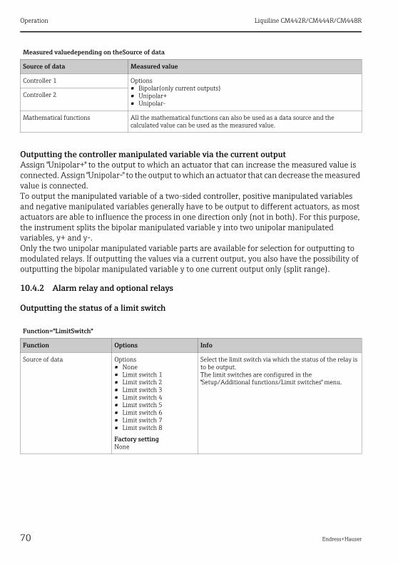
Operation Liquiline CM442R/CM444R/CM448R
70 Endress+Hauser
Outputting the controller manipulated variable via the current outputAssign "Unipolar+" to the output to which an actuator that can increase the measured value is connected. Assign "Unipolar-" to the output to which an actuator that can decrease the measured value is connected.To output the manipulated variable of a two-sided controller, positive manipulated variables and negative manipulated variables generally have to be output to different actuators, as most actuators are able to influence the process in one direction only (not in both). For this purpose, the instrument splits the bipolar manipulated variable y into two unipolar manipulated variables, y+ and y-.Only the two unipolar manipulated variable parts are available for selection for outputting to modulated relays. If outputting the values via a current output, you also have the possibility of outputting the bipolar manipulated variable y to one current output only (split range).
10.4.2 Alarm relay and optional relays
Outputting the status of a limit switch
Controller 1 Options• Bipolar(only current outputs)• Unipolar+• Unipolar-
Controller 2
Mathematical functions All the mathematical functions can also be used as a data source and the calculated value can be used as the measured value.
Function="LimitSwitch"
Function Options Info
Source of data Options• None• Limit switch 1• Limit switch 2• Limit switch 3• Limit switch 4• Limit switch 5• Limit switch 6• Limit switch 7• Limit switch 8
Factory settingNone
Select the limit switch via which the status of the relay is to be output.The limit switches are configured in the "Setup/Additional functions/Limit switches" menu.
Measured valuedepending on theSource of data
Source of data Measured value
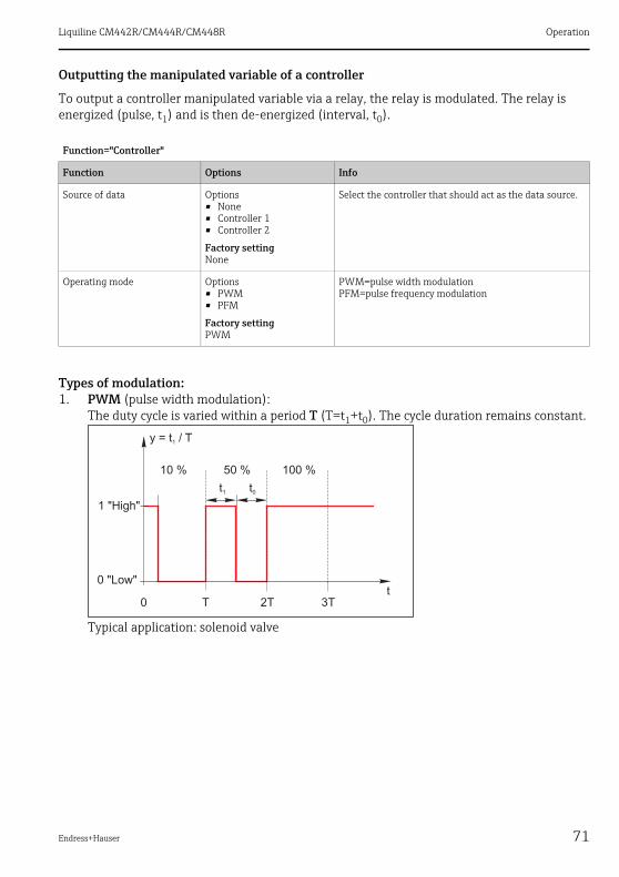
Liquiline CM442R/CM444R/CM448R Operation
Endress+Hauser 71
Outputting the manipulated variable of a controller
To output a controller manipulated variable via a relay, the relay is modulated. The relay is energized (pulse, t1) and is then de-energized (interval, t0).
Types of modulation:1. PWM (pulse width modulation):
The duty cycle is varied within a period T (T=t1+t0). The cycle duration remains constant.
Typical application: solenoid valve
Function="Controller"
Function Options Info
Source of data Options• None• Controller 1• Controller 2
Factory settingNone
Select the controller that should act as the data source.
Operating mode Options• PWM• PFM
Factory settingPWM
PWM=pulse width modulationPFM=pulse frequency modulation

Operation Liquiline CM442R/CM444R/CM448R
72 Endress+Hauser
2. PFM (pulse frequency modulation):Here, pulses of a constant length (t1) are output and the interval between the pulses varies (t0). At a maximum frequency, t1 = t0.
Typical application: dosing pump
Function="Controller"
Function Options Info
Actuator type Options• None• Unipolar-• Unipolar+
Factory settingNone
Here you specify what part of the controller should power the relay. "Unipolar+" is the part of the manipulated variable which the controller uses to increase the process value (e.g. for heating purposes). On the other hand, select "Unipolar-" if you want to connect an actuator to the relay that causes the controlled variable to drop (e.g. for cooling purposes).
Cycle duration
Operating mode="PWM"
(Shortest turn-on time) to 999.0 s
Factory setting10.0 s
Specify the cycle duration within which the duty cycle should be varied (only PWM).
The settings for Cycle duration and Shortest turn-on time mutually affect one another. The following applies: Cycle duration ≥ Shortest turn-on time.
Shortest turn-on time
Operating mode="PWM"
0.3 s to (Cycle duration)
Factory setting0.3 s
Pulses that are shorter than this limit value are not output in order to conserve the actuator.
Maximum frequency
Operating mode="PFM"
1 to 180 min-1
Factory setting60 min-1
Maximum number of pulses per minuteThe controller calculates the pulse duration based on this setting.
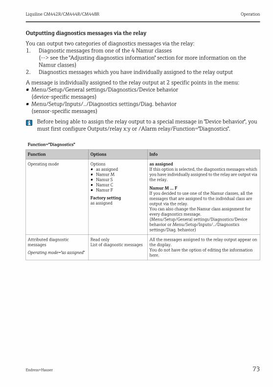
Liquiline CM442R/CM444R/CM448R Operation
Endress+Hauser 73
Outputting diagnostics messages via the relay
You can output two categories of diagnostics messages via the relay:1. Diagnostic messages from one of the 4 Namur classes
(--> see the "Adjusting diagnostics information" section for more information on the Namur classes)
2. Diagnostics messages which you have individually assigned to the relay output
A message is individually assigned to the relay output at 2 specific points in the menu:• Menu/Setup/General settings/Diagnostics/Device behavior
(device-specific messages)• Menu/Setup/Inputs/../Diagnostics settings/Diag. behavior
(sensor-specific messages)
Before being able to assign the relay output to a special message in "Device behavior", you must first configure Outputs/relay x:y or /Alarm relay/Function="Diagnostics".
Function="Diagnostics"
Function Options Info
Operating mode Options• as assigned• Namur M• Namur S• Namur C• Namur F
Factory settingas assigned
as assignedIf this option is selected, the diagnostics messages which you have individually assigned to the relay are output via the relay.
Namur M ... FIf you decided to use one of the Namur classes, all the messages that are assigned to the individual class are output via the relay.You can also change the Namur class assignment for every diagnostics message.(Menu/Setup/General settings/Diagnostics/Device behavior or Menu/Setup/Inputs/../Diagnostics settings/Diag. behavior)
Attributed diagnostic messages
Operating mode="as assigned"
Read onlyList of diagnostic messages
All the messages assigned to the relay output appear on the display.You do not have the option of editing the information here.
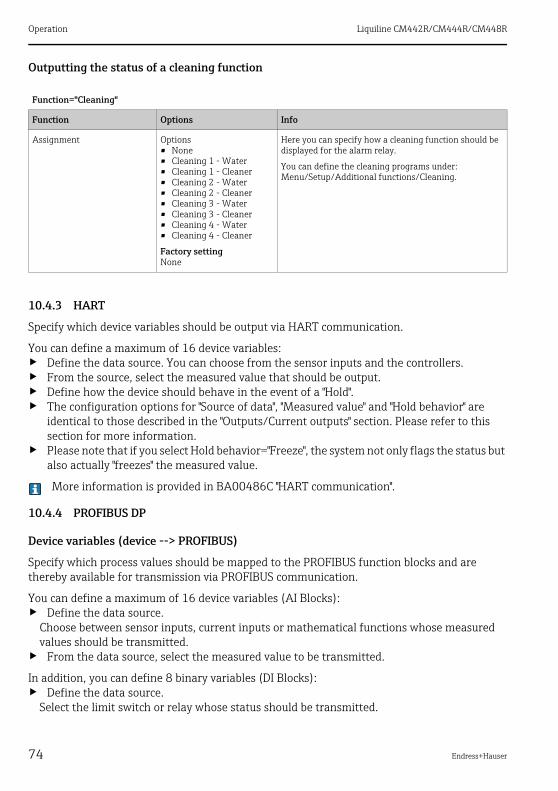
Operation Liquiline CM442R/CM444R/CM448R
74 Endress+Hauser
Outputting the status of a cleaning function
10.4.3 HART
Specify which device variables should be output via HART communication.
You can define a maximum of 16 device variables:‣ Define the data source. You can choose from the sensor inputs and the controllers.‣ From the source, select the measured value that should be output.‣ Define how the device should behave in the event of a "Hold".‣ The configuration options for "Source of data", "Measured value" and "Hold behavior" are
identical to those described in the "Outputs/Current outputs" section. Please refer to this section for more information.
‣ Please note that if you select Hold behavior="Freeze", the system not only flags the status but also actually "freezes" the measured value.
More information is provided in BA00486C "HART communication".
10.4.4 PROFIBUS DP
Device variables (device --> PROFIBUS)
Specify which process values should be mapped to the PROFIBUS function blocks and are thereby available for transmission via PROFIBUS communication.
You can define a maximum of 16 device variables (AI Blocks):‣ Define the data source.
Choose between sensor inputs, current inputs or mathematical functions whose measured values should be transmitted.
‣ From the data source, select the measured value to be transmitted.
In addition, you can define 8 binary variables (DI Blocks):‣ Define the data source.
Select the limit switch or relay whose status should be transmitted.
Function="Cleaning"
Function Options Info
Assignment Options• None• Cleaning 1 - Water• Cleaning 1 - Cleaner• Cleaning 2 - Water• Cleaning 2 - Cleaner• Cleaning 3 - Water• Cleaning 3 - Cleaner• Cleaning 4 - Water• Cleaning 4 - Cleaner
Factory settingNone
Here you can specify how a cleaning function should be displayed for the alarm relay.
You can define the cleaning programs under:Menu/Setup/Additional functions/Cleaning.
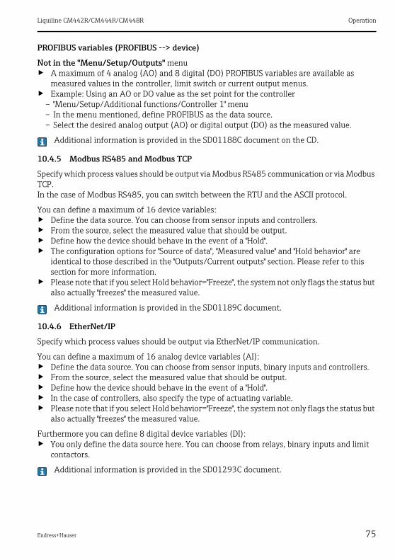
Liquiline CM442R/CM444R/CM448R Operation
Endress+Hauser 75
PROFIBUS variables (PROFIBUS --> device)
Not in the "Menu/Setup/Outputs" menu‣ A maximum of 4 analog (AO) and 8 digital (DO) PROFIBUS variables are available as
measured values in the controller, limit switch or current output menus.‣ Example: Using an AO or DO value as the set point for the controller
– "Menu/Setup/Additional functions/Controller 1" menu– In the menu mentioned, define PROFIBUS as the data source.– Select the desired analog output (AO) or digital output (DO) as the measured value.
Additional information is provided in the SD01188C document on the CD.
10.4.5 Modbus RS485 and Modbus TCP
Specify which process values should be output via Modbus RS485 communication or via Modbus TCP.In the case of Modbus RS485, you can switch between the RTU and the ASCII protocol.
You can define a maximum of 16 device variables:‣ Define the data source. You can choose from sensor inputs and controllers.‣ From the source, select the measured value that should be output.‣ Define how the device should behave in the event of a "Hold".‣ The configuration options for "Source of data", "Measured value" and "Hold behavior" are
identical to those described in the "Outputs/Current outputs" section. Please refer to this section for more information.
‣ Please note that if you select Hold behavior="Freeze", the system not only flags the status but also actually "freezes" the measured value.
Additional information is provided in the SD01189C document.
10.4.6 EtherNet/IP
Specify which process values should be output via EtherNet/IP communication.
You can define a maximum of 16 analog device variables (AI):‣ Define the data source. You can choose from sensor inputs, binary inputs and controllers.‣ From the source, select the measured value that should be output.‣ Define how the device should behave in the event of a "Hold".‣ In the case of controllers, also specify the type of actuating variable.‣ Please note that if you select Hold behavior="Freeze", the system not only flags the status but
also actually "freezes" the measured value.
Furthermore you can define 8 digital device variables (DI):‣ You only define the data source here. You can choose from relays, binary inputs and limit
contactors.
Additional information is provided in the SD01293C document.

Operation Liquiline CM442R/CM444R/CM448R
76 Endress+Hauser
10.5 Binary inputs and outputsThe optional "DIO" hardware module with 2 digital inputs and 2 digital outputs enables the following:• via a digital input signal
– measuring range switching for conductivity (upgrade code required, see accessories)– an external hold– a cleaning interval to be triggered– a PID controller to be switched on and off, e.g. via the proximity switch of CCA250– the use of the input as an "analog input" for pulse-frequency modulation (PFM)
• via a digital output signal– the static transmission (similar to a relay) of diagnostic states, point level switch states etc.– the dynamic transmission (comparable to a non-wearing "analog output") of PFM signals,
e.g. to control dosing pumps.

Liquiline CM442R/CM444R/CM448R Operation
Endress+Hauser 77
10.5.1 Application examples
Chlorine control with feedforward control
a0020123
Fig. 59: Example of chlorine control with feedforward control
1 Connection of the inductive proximity switch INS of the CCA250 assembly at the digital input of the DIO module for enabling the controller
2 Connection of the signal from a flowmeter to the digital input of the DIO module using the pulse-frequency modulation (=PFM, setting in the Liquiline firmware) for feedforward control
3 Activation of a (pulse) dosing pump via a digital output of the DIO module using the PFMA Dosing pump
Operation Liquiline CM442R/CM444R/CM448R
78 Endress+Hauser
Chlorine control with feedforward controlUtilize the advantage of the effectively wear-free control with binary outputs versus a control system with relay. It is possible to achieve virtually continuous dosing using a dosing pump with higher input frequency through pulse frequency modulation (PFM).
1. Connect the proximity switch INS from assembly CCA250 to a digital input of the DIO module. Configure a controller in the software, selecting the binary input for the function "Controller Enable" which the proximity switch is connected to. Leave the "Signal type" in the inputs menu at the factory setting "Static signal" as the selected input.
2. Connect the flowmeter value to the second input of the DIO module. Set the "Signal type" for this input to "PFM" in the inputs menu and select the corresponding measured value.
You can now use this input in the controller menu as the disturbance variable for your controller 1). To do so, in the submenu "Disturbance variable" select the binary input to which you connected the flow measured value as the "Source of data."
3. You can activate a dosing pump through PFM via a digital output of the DIO module. In the outputs menu, set the "Signal type" of the corresponding binary output to "PFM" and use the previously configured controller as the "Source of data." Observe your dosing's direction of action, so that you correctly install the "Actuator type."
You must make additional settings in the controller menu to fully customize the control to your process conditions.
1) An activation code, Order No. 71211288, is necessary for the "feedforward control" function.

Liquiline CM442R/CM444R/CM448R Operation
Endress+Hauser 79
CM44xR as cleaning master
CM44xR as "cleaning master"1. An external trigger actuates a cleaning at the master. A cleaning unit is connected over a
relay or a binary output, for example.2. The cleaning trigger is transferred to another device via a binary output. This does not have
its own connected cleaning unit, but its sensors are installed in the medium affected by cleaning the master and are set to hold by the trigger.
3. The trigger is transferred via an additional binary output to another device, whose connected sensors have their own cleaning units. The signal can be used to simultaneously activate a self-cleaning with the master.
a0020124
Fig. 60: Example of a central cleaning control
1 External cleaning trigger at the binary input2 Transferring the external hold over binary output to other measuring devices without connected cleaning functions3 Transferring the cleaning trigger over a binary output to other self-cleaning measuring points

Operation Liquiline CM442R/CM444R/CM448R
80 Endress+Hauser
10.5.2 Binary input configuration
Path: Menu/Setup/Inputs/Binary input x:y1)
Function Options Info
Binary input Options• Off• On
Factory settingOn
Switching the input on/off
Signal type Options• Static signal• PFM
Factory settingStatic signal
Select the signal type.
Static signalUse this setting to read out the position of, for example, an on/off switch, an inductive proximity switch or a PLC binary output.Signal application: for measuring range switching, acceptance of an external hold, as a cleaning trigger or for controller activation
PFMThe PFM setting produces a pulse-frequency-modulated signal that is subsequently available on the device as a quasi-continuous process value.Example: Measuring signal of a flowmeter
Signal type= "Static signal"
Signal level Options• High• Low
Factory settingHigh
Determine which input signal levels should activate, for example, measuring range switching or a cleaning.
HighInput signals between 11 and 30 V DC
LowInput signals between 0 and 5 V DC
Signal type= "PFM"
Max. frequency 100.00 to 1000.00 Hz
Factory setting1000.00 Hz
Maximum frequency of the PFM input signalIs to equal the maximum possible upper limit of the measuring range.If the value selected is too small, higher frequencies will not be detected. If the value is too large, on the other hand, the resolution for small frequencies will be relatively inexact.
Meas. value format Options• #• #.#• #.##• #.###
Factory setting#.##
Specify the number of decimal places.

Liquiline CM442R/CM444R/CM448R Operation
Endress+Hauser 81
10.5.3 Configuration of binary outputs
Input mode Options• Frequency• Parameter
Factory settingFrequency
FrequencyDisplay in Hz in the measuring menu
ParameterYou subsequently determine the parameter name and unit. These are then displayed in the measuring menu.
Parameter name
Input mode= "Parameter"
Free text Define a name for the parameter, e.g. "flow rate."
Unit of measure
Input mode= "Parameter"
Free text Determine the unit in which your parameter should be displayed, e.g." l/min."
Lower range value
Input mode= "Parameter"
-2000.00 to 0.00
Factory setting0.00
Your previously defined unit is additionally displayed.The start of measuring range corresponds to a frequency of 0 Hz.
Upper range value
Input mode= "Parameter"
0.00 to 10000.00
Factory setting0.00
The end of measuring range corresponds to the maximum frequency defined above. The displayed unit is the one predefined by you.
Damping 0 to 600 s
Factory setting0 s
The damping generates a floating average curve of the measured value over the specified time.
1) x:y = slot no. : input number
Path: Menu/Setup/Outputs/Binary output x:y1)
Function Options Info
Binary output Options• Off• On
Factory settingOn
Switching the output on/off
Signal type Options• Static signal• PFM
Factory settingStatic signal
Select the signal type.
Static signalComparable to a relay: output of a diagnostic status or a limit contactor
PFMYou can output a measured value, e.g. the chlorine value or the manipulated variable of a controller.It functions as a "wear-free" switching contact that can be used to activate a dosing pump, for example.
Path: Menu/Setup/Inputs/Binary input x:y1)
Function Options Info

Operation Liquiline CM442R/CM444R/CM448R
82 Endress+Hauser
Signal type= "PFM"
Max. frequency 1.00 to 1000.00 Hz
Factory setting1000.00 Hz
Maximum frequency of the PFM output signalIs to equal the maximum possible upper limit of the measuring range.
Meas. value format Options• #• #.#• #.##• #.###
Factory setting#.##
Specify the number of decimal places.
Source of data Options• None• Sensor inputs• Binary inputs• Controller• Fieldbus signals• Mathematical functions
Factory settingNone
Source, whose value should be read out as a frequency over the binary output.
Measuring value
Source of data = an input
Selection dependent on "Source of data"
"Inputs" = everything except controllers
Actuator type
Source of data = a controller
Options• None• Bipolar• Unipolar+• Unipolar-
Factory settingNone
Determines which controller component the connected actuator, e.g. the dosing pump, should trigger.
Unipolar+Part of the manipulated variable that the controller uses to increase the process value
Unipolar-For connected actuators that decrease the controlled variable
Bipolar"Split range"
Hold behavior Options• Freeze• Fixed value• None
Factory settingFreeze
FreezeThe device freezes the last value.
Fixed valueYou define a fixed current value that is transmitted at the output.
NoneA hold does not affect this output.
Hold value
Hold behavior= "Fixed value"
0 to 100 %
Factory setting0 %
Path: Menu/Setup/Outputs/Binary output x:y1)
Function Options Info

Liquiline CM442R/CM444R/CM448R Operation
Endress+Hauser 83
Error behavior Options• Freeze• Fixed value
Factory settingFixed value
FreezeThe device freezes the last value.
Fixed valueYou define a fixed current value that is transmitted at the output.
Error value
Error behavior= "Fixed value"
0 to 100 %
Factory setting0 %
Signal type= "Static signal"
Function Options• None• Limit switches• Diagnostics message• Cleaning
Factory settingNone
Source for the outputted switching state
The following functions depend on the option selected.Function = "None" switches the function off without requiring any settings.
Assignments
Function= "Cleaning"
Multiple selection• Cleaning 1 - Water
...• Cleaning 4 - Cleaner
Here you can decide which binary outputs should be used for activating the valves and pumps. Here you concretely assign a control signal to the binary output for the cleaner/water dosing of a cleaning program.
You can define the cleaning programs under:Menu/Setup/Additional functions/Cleaning.
Data sources
Function= "Limit switches"
Multiple selection• Limit switch 1
...• Limit switch 8
Select the limit contactor to be transmitted over the binary output.The limit switches are configured in the "Setup/Additional functions/Limit switches" menu.
Operating mode
Function= "Diagnostics message"
Options• as assigned• Namur M• Namur S• Namur C• Namur F
Factory settingas assigned
as assignedWith this selection, the diagnosis messages are transmitted over the binary output that you individually allocated to it.
Namur M ... FWhen you choose one of the Namur classes, all messages allocated to that respective class are output.You can also change the Namur class assignment for every diagnostics message.(Menu/Setup/General settings/Diagnostics/Device behavior or Menu/Setup/Inputs/../Diagnostics settings/Diag. behavior)
1) x:y = slot no. : input number
Path: Menu/Setup/Outputs/Binary output x:y1)
Function Options Info

Operation Liquiline CM442R/CM444R/CM448R
84 Endress+Hauser
10.6 Additional functions
10.6.1 Limit switch
There are different ways of configuring a limit switch:• Assigning a switch-on and switch-off point• Assigning a switch-on and switch-off delay for a relay• Setting an alarm threshold and also outputting an error message• Starting a cleaning function
Path: Menu/Setup/Additional functions/Limit switches/Limit switches 1 to 8
Function Options Info
Source of data Options• None• Connected sensors
Factory settingNone
Specify the input or output which should be the source of data for the limit switch.
Measuring value Options• None• Depends on theSource of
data
Factory settingNone
The measured value you can select depends on the option selected under "Source of data".
Measured valuedepending on theSource of data
Source of data Measured value
pH Glass Options• Raw value mV• pH• Temperature
pH ISFET
ORP Options• Temperature• ORP mV• ORP %
Oxygen (amp.) Options• Temperature• Partial pressure• Concentration liquid• Saturation• Raw value nA (only Oxygen (amp.))• Raw value μs (only Oxygen (opt. WW))
Oxygen (opt. WW)
Cond i Options• Temperature• Conductivity• Resistance (only Cond c)• Concentration (only Cond i)
Cond c

Liquiline CM442R/CM444R/CM448R Operation
Endress+Hauser 85
You can monitor the manipulated variable by assigning the controller manipulated variable to a limit switch (e.g. configure a dosing time alarm).
Chlorine Options• Temperature• Current• Concentration
ISE Options• Temperature• pH• Ammonium• Nitrate• Potassium• Chloride
TU/TS Options• Temperature• Turbidity g/l• Turbidity FNU
Nitrate Options• Temperature• NO3• NO3-N
SAC Options• Temperature• SAC• Transm.• Absorption• COD• BOD
Controller 1 Options• Bipolar(only current outputs)• Unipolar+• Unipolar-
Controller 2
Mathematical functions All the mathematical functions can also be used as a data source and the calculated value can be used as the measured value.
Path: Menu/Setup/Additional functions/Limit switches/Limit switches 1 to 8
Function Options Info
Cleaning program Options• None• Cleaning 1• Cleaning 2• Cleaning 3• Cleaning 4
Factory settingNone
Use this function to choose the cleaning instance which should be started when the limit switch is active.
Measured valuedepending on theSource of data
Source of data Measured value
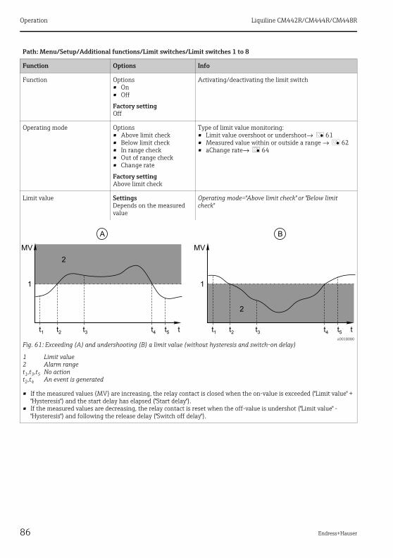
Operation Liquiline CM442R/CM444R/CM448R
86 Endress+Hauser
Function Options• On• Off
Factory settingOff
Activating/deactivating the limit switch
Operating mode Options• Above limit check• Below limit check• In range check• Out of range check• Change rate
Factory settingAbove limit check
Type of limit value monitoring:• Limit value overshoot or undershoot→ å 61• Measured value within or outside a range → å 62• aChange rate→ å 64
Limit value SettingsDepends on the measured value
Operating mode="Above limit check" or "Below limit check"
a0018080
Fig. 61: Exceeding (A) and undershooting (B) a limit value (without hysteresis and switch-on delay)
1 Limit value2 Alarm ranget1,t3,t5 No actiont2,t4 An event is generated
• If the measured values (MV) are increasing, the relay contact is closed when the on-value is exceeded ("Limit value" + "Hysteresis") and the start delay has elapsed ("Start delay").
• If the measured values are decreasing, the relay contact is reset when the off-value is undershot ("Limit value" - "Hysteresis") and following the release delay ("Switch off delay").
Path: Menu/Setup/Additional functions/Limit switches/Limit switches 1 to 8
Function Options Info

Liquiline CM442R/CM444R/CM448R Operation
Endress+Hauser 87
Range lower value SettingsDepends on the measured value
Operating mode="In range check" or "Out of range check"
Range upper value
a0018081
Fig. 62: Monitoring outside (A) and within (B) a range (without hysteresis and switch-on delay)
1 End of range2 Start of range3 Alarm ranget1, 2, 3, 4 An event is generated
• If the measured values (MV) are increasing, the relay contact is closed when the on-value is exceeded ("Range lower value" + "Hysteresis") and the start delay has elapsed ("Start delay").
• If the measured values are decreasing, the relay contact is reset when the off-value is undershot ("Range upper value" - "Hysteresis") and following the release delay ("Switch off delay").
Hysteresis SettingsDepends on the measured value
Operating mode="In range check", "Out of range check","Above limit check" or "Below limit check"
a0018140
Fig. 63: Hysteresis taking the example of limit value overshoot
1 Limit value2 Alarm range3 Hysteresis ranget1, t2 An event is generated
The hysteresis is needed to ensure a stable switching behavior.
The device software adds or subtracts the value set here to/from the limit value (Limit value, Range lower value or Range upper value). This results in the double "Hysteresis" value for the hysteresis range around the limit value.An event is then only generated if the measured value (MV) completely passes through the hysteresis range. → å 63
Path: Menu/Setup/Additional functions/Limit switches/Limit switches 1 to 8
Function Options Info

Operation Liquiline CM442R/CM444R/CM448R
88 Endress+Hauser
Start delay 0 to 9999 s
Factory setting0 s
Operating mode="In range check", "Out of range check","Above limit check" or "Below limit check"
Synonyms: pick-up and drop-out delaySwitch off delay
Delta value SettingsDepends on the measured value
Operating mode="Change rate"
The slope of the measured value (MV) is monitored in this mode.An event is generated if, in the given timeframe (Delta time), the measured value increases or decreases by more than the specified value (Delta value). No further event is generated if the value continues to experience such a steep increase or decrease.If the slope is back below the limit value, the alarm status is reset after a preset time (Auto Confirm).
Events are triggered by the following conditions in the example given:
t2 - t1 < "Delta time" and ΔMV1 > "Delta value"t4 - t3 > "Auto Confirm" and ΔMV2 < "Delta value"t6 - t5 < "Delta time" and ΔMV3 > ΔMV
Delta time 00:01 to 23:59
Factory setting01:00
Auto Confirm 00:01 to 23:59
Factory setting00:01
a0018100
Fig. 64: aChange rate
Path: Menu/Setup/Additional functions/Limit switches/Limit switches 1 to 8
Function Options Info

Liquiline CM442R/CM444R/CM448R Operation
Endress+Hauser 89
10.6.2 Controller
Controller structure in Laplace representation
The controller structure of the device comprises set point damping at the input to prevent erratic changes in the manipulated variable if the set point changes. The difference between the set point w and the controlled variable (measured value) X results in the control deviation which is filtered by a neutral zone.The neutral zone is used to suppress control deviations (e) that are too small. The control deviation thus filtered is now fed to the actual PID controller which divides into three parts based on the P (proportional), I (integral) and D (derivative) values (top-down). The integral section (middle) also comprises an anti-windup mechanism for limiting the integrator. A low-pass filter is added to the D-section to damp hard D-terms in the manipulated variable. The sum of the 3 sections results in the internal controller manipulated variable which is limited according to the settings (for PID-2s to -100% to +100%).The graphic does not illustrate a downstream filter for limiting the rate of change of the manipulated variable (can be configured in the menu in "Max Y change rate /s").
In the menu do not configure the gain Kp. Instead configure the reciprocal value, the proportional band Xp (Kp=1/Xp).
a0015007
Fig. 65: Block diagram of the controller structure
ABKpTnTvTwTwuP
Neutral zoneOutput limitingGain (P-value)Integral action time (I-value)Derivative action time (D-value)Time constant for set point dampingTime constant for anti-windup feedbackProportional value
IDαTvewxy
Integral valueDerivative valueDamping time constant with α= 0 to 1Control deviationSet pointControlled variableManipulated variable
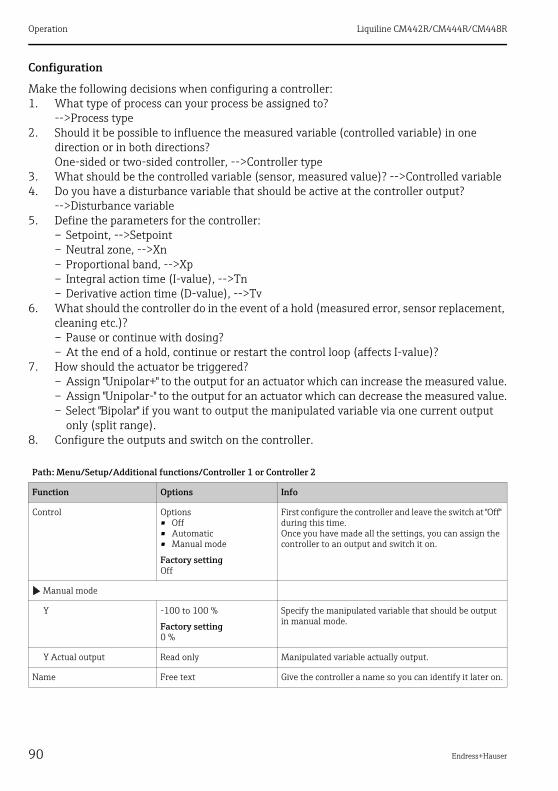
Operation Liquiline CM442R/CM444R/CM448R
90 Endress+Hauser
Configuration
Make the following decisions when configuring a controller:1. What type of process can your process be assigned to?
-->Process type2. Should it be possible to influence the measured variable (controlled variable) in one
direction or in both directions?One-sided or two-sided controller, -->Controller type
3. What should be the controlled variable (sensor, measured value)? -->Controlled variable4. Do you have a disturbance variable that should be active at the controller output?
-->Disturbance variable5. Define the parameters for the controller:
– Setpoint, -->Setpoint– Neutral zone, -->Xn– Proportional band, -->Xp– Integral action time (I-value), -->Tn– Derivative action time (D-value), -->Tv
6. What should the controller do in the event of a hold (measured error, sensor replacement, cleaning etc.)?– Pause or continue with dosing?– At the end of a hold, continue or restart the control loop (affects I-value)?
7. How should the actuator be triggered?– Assign "Unipolar+" to the output for an actuator which can increase the measured value.– Assign "Unipolar-" to the output for an actuator which can decrease the measured value.– Select "Bipolar" if you want to output the manipulated variable via one current output
only (split range).8. Configure the outputs and switch on the controller.
Path: Menu/Setup/Additional functions/Controller 1 or Controller 2
Function Options Info
Control Options• Off• Automatic• Manual mode
Factory settingOff
First configure the controller and leave the switch at "Off" during this time.Once you have made all the settings, you can assign the controller to an output and switch it on.
Manual mode
Y -100 to 100 %
Factory setting0 %
Specify the manipulated variable that should be output in manual mode.
Y Actual output Read only Manipulated variable actually output.
Name Free text Give the controller a name so you can identify it later on.

Liquiline CM442R/CM444R/CM448R Operation
Endress+Hauser 91
Controller Enable Options• None• Binary inputs• Limit switch• Fieldbus variables
Factory settingNone
In connection with the DIO module, you can select a binary input signal, e.g. from an inductive proximity switch, as a source for enabling the controller.
Setup Level Options• Standard• Advanced
Factory settingStandard
The Setup Level changes the number of parameters that can be configured.If you choose "Standard" the other controller parameters are active nevertheless. The system uses the factory settings which usually suffice in most cases.
Process type Options• Inline• Batch
Factory settingInline
Decide what type of process best describes your particular process (see the explanation below).
Batch processThe medium is in a closed system.The task of the control system is to dose in such a way that the measured value (controlled variable) changes from its start value to its target value. No more dosing is needed once the setpoint has been reached and the system is stable. If the target value is overshot, a two-sided control system can compensate for this.In the case of 2-sided batch control systems, a neutral zone is used/configured to suppress oscillations around the setpoint.
In-line processIn an in-line process, the control system works with the medium flowing by in the process. Here, the controller has the task of using the manipulated variable to set a mixture ratio between the medium and dosing agent such that the resulting measured variable corresponds to the setpoint. The properties and volume of the medium flow can change at any time and the controller has to react to these changes on a continuous basis. If the flow rate and medium remain constant, the manipulated variable can also assume a fixed value once the process has settled. Since the control process is never "finished" here, this type of control is also referred to as continuous control.
A mixture of both process types can often be found in practice: the semi-batch process. Depending on the ratio between the flow and the container volume, this arrangement behaves either like a batch process or an in-line process.
Path: Menu/Setup/Additional functions/Controller 1 or Controller 2
Function Options Info

Operation Liquiline CM442R/CM444R/CM448R
92 Endress+Hauser
Controller type Options• PID 1-sided• PID 2-sided
Factory settingPID 2-sided
Depending on the actuator connected, you influence the process in just one direction (e.g. heating) or in both directions (e.g. heating and cooling).
A 2-sided controller can output a manipulated variable in the range from -100% to +100%, i.e. the manipulated variable is bipolar. The manipulated variable is positive if the controller should increase the process value. In the case of a pure P-controller, this means that the value of the controlled variable x is smaller than the setpoint w. On the other hand, the manipulated variable is negative if the process value should be decreased. The value for x is greater than the setpoint w.The following graphic illustrates the relationship y = (w-x)/Xp:
Effective direction
Controller type="PID 1-sided"
Options• Direct• Reverse
Factory settingReverse
In what direction should the controller influence the measured value?• The measured value should increase as a result of
dosing (e.g. heating) --> "Reverse"• The measured value should decrease as a result of
dosing (e.g. cooling) --> "Direct"
A 1-sided controller has a unipolar manipulated variable, i.e. it can only influence the process in one direction. If the controller should increase the process value, set "Reverse" as the effective direction. The controller then becomes active when the process value is too small (range A).With the "Direct" effective direction, the controller acts as a "downwards controller". It becomes active when the process value (e.g. the temperature) is too high (range B).
The red curve shows overlap between the curves of the two 1-sided controllers.
Path: Menu/Setup/Additional functions/Controller 1 or Controller 2
Function Options Info

Liquiline CM442R/CM444R/CM448R Operation
Endress+Hauser 93
Controlled variable
Source of data Options• Sensors• Current inputs• Fieldbus signals• Binary inputs• Mathematical functions
Factory settingNone
Specify the input or output which should be the source of data for the controlled variable.
Measured value Options• None• Depends on theSource of
data
Factory settingNone
Specify the measured value that should be your controlled variable.The measured value you can select depends on the option selected under "Source of data".
Setpoint Not available if a fieldbus has been selected as the "Source of data"
Setpoint Range of adjustment and factory settingDepends on the "Source of data"
Specify the setpoint for the controlled variable.
Path: Menu/Setup/Additional functions/Controller 1 or Controller 2
Function Options Info
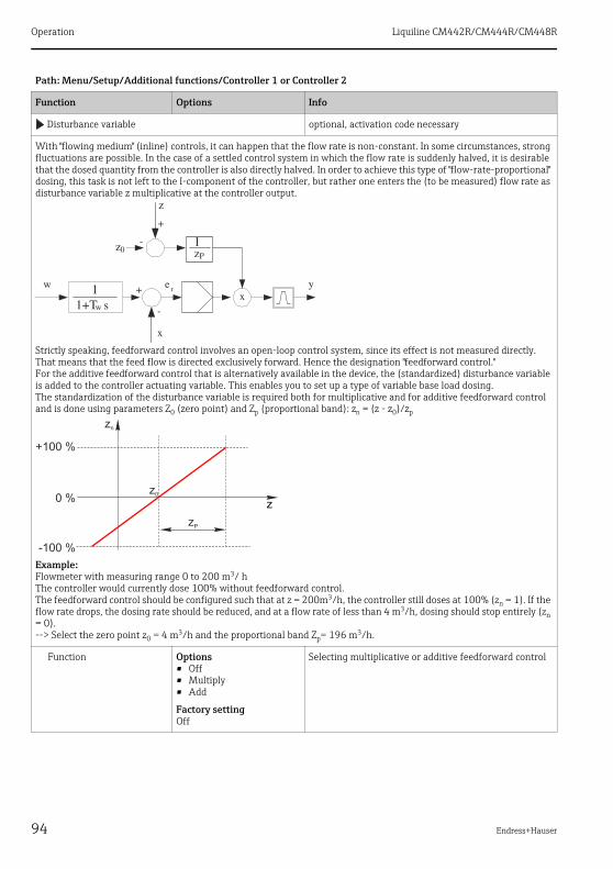
Operation Liquiline CM442R/CM444R/CM448R
94 Endress+Hauser
Disturbance variable optional, activation code necessary
With "flowing medium" (inline) controls, it can happen that the flow rate is non-constant. In some circumstances, strong fluctuations are possible. In the case of a settled control system in which the flow rate is suddenly halved, it is desirable that the dosed quantity from the controller is also directly halved. In order to achieve this type of "flow-rate-proportional" dosing, this task is not left to the I-component of the controller, but rather one enters the (to be measured) flow rate as disturbance variable z multiplicative at the controller output.
Strictly speaking, feedforward control involves an open-loop control system, since its effect is not measured directly. That means that the feed flow is directed exclusively forward. Hence the designation "feedforward control."For the additive feedforward control that is alternatively available in the device, the (standardized) disturbance variable is added to the controller actuating variable. This enables you to set up a type of variable base load dosing.The standardization of the disturbance variable is required both for multiplicative and for additive feedforward control and is done using parameters Z0 (zero point) and Zp (proportional band): zn = (z - z0)/zp
Example:Flowmeter with measuring range 0 to 200 m3/ hThe controller would currently dose 100% without feedforward control.The feedforward control should be configured such that at z = 200m3/h, the controller still doses at 100% (zn = 1). If the flow rate drops, the dosing rate should be reduced, and at a flow rate of less than 4 m3/h, dosing should stop entirely (zn = 0).--> Select the zero point z0 = 4 m3/h and the proportional band Zp= 196 m3/h.
Function Options• Off• Multiply• Add
Factory settingOff
Selecting multiplicative or additive feedforward control
Path: Menu/Setup/Additional functions/Controller 1 or Controller 2
Function Options Info
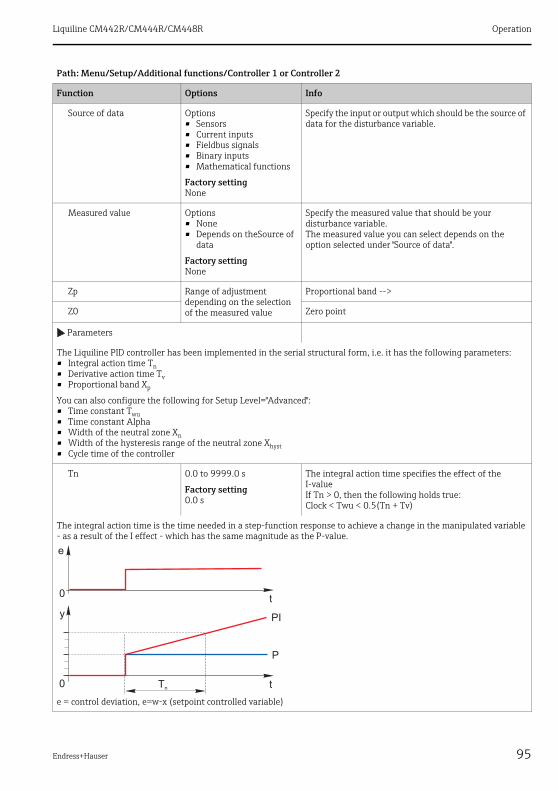
Liquiline CM442R/CM444R/CM448R Operation
Endress+Hauser 95
Source of data Options• Sensors• Current inputs• Fieldbus signals• Binary inputs• Mathematical functions
Factory settingNone
Specify the input or output which should be the source of data for the disturbance variable.
Measured value Options• None• Depends on theSource of
data
Factory settingNone
Specify the measured value that should be your disturbance variable.The measured value you can select depends on the option selected under "Source of data".
Zp Range of adjustment depending on the selection of the measured value
Proportional band -->
Z0 Zero point
Parameters
The Liquiline PID controller has been implemented in the serial structural form, i.e. it has the following parameters:• Integral action time Tn• Derivative action time Tv• Proportional band Xp
You can also configure the following for Setup Level="Advanced":• Time constant Twu• Time constant Alpha• Width of the neutral zone Xn• Width of the hysteresis range of the neutral zone Xhyst• Cycle time of the controller
Tn 0.0 to 9999.0 s
Factory setting0.0 s
The integral action time specifies the effect of the I-valueIf Tn > 0, then the following holds true:Clock < Twu < 0.5(Tn + Tv)
The integral action time is the time needed in a step-function response to achieve a change in the manipulated variable - as a result of the I effect - which has the same magnitude as the P-value.
e = control deviation, e=w-x (setpoint controlled variable)
Path: Menu/Setup/Additional functions/Controller 1 or Controller 2
Function Options Info
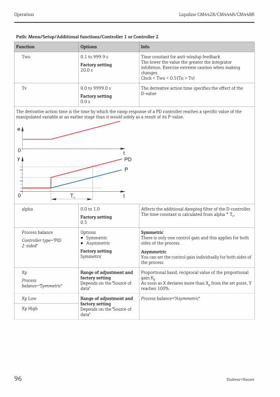
Operation Liquiline CM442R/CM444R/CM448R
96 Endress+Hauser
Twu 0.1 to 999.9 s
Factory setting20.0 s
Time constant for anti-windup feedbackThe lower the value the greater the integrator inhibition. Exercise extreme caution when making changes.Clock < Twu < 0.5(Tn + Tv)
Tv 0.0 to 9999.0 s
Factory setting0.0 s
The derivative action time specifies the effect of the D-value
The derivative action time is the time by which the ramp response of a PD controller reaches a specific value of the manipulated variable at an earlier stage than it would solely as a result of its P-value.
alpha 0.0 to 1.0
Factory setting0.3
Affects the additional damping filter of the D-controller. The time constant is calculated from alpha * Tv.
Process balance
Controller type="PID 2-sided"
Options• Symmetric• Asymmetric
Factory settingSymmetric
SymmetricThere is only one control gain and this applies for both sides of the process.
AsymmetricYou can set the control gain individually for both sides of the process.
Xp
Process balance="Symmetric"
Range of adjustment and factory settingDepends on the "Source of data"
Proportional band, reciprocal value of the proportional gain KpAs soon as X deviates more than Xp from the set point, Y reaches 100%.
Xp Low Range of adjustment and factory settingDepends on the "Source of data"
Process balance="Asymmetric"
Xp High
Path: Menu/Setup/Additional functions/Controller 1 or Controller 2
Function Options Info

Liquiline CM442R/CM444R/CM448R Operation
Endress+Hauser 97
Xn
Process balance="Symmetric"
Range of adjustment and factory settingDepends on the "Source of data"
Tolerance range about the setpoint that prevents minor oscillations about the setpoint if using two-sided control loops.
XN Low Range of adjustment and factory settingDepends on the "Source of data"
Process balance="Asymmetric"
XN High
XHyst 0.0 to 99.9 %
Factory setting0.0 %
Width of the hysteresis range of the neutral zone, relative component of Xn
The graphic illustrates the manipulated variable (with a pure P-controller ) over the control deviation e (set point minus controlled variable). Very low control deviations are set to zero. Control deviations > Xn are processed "in the normal way". Via Xhyst it is possible to configure a hysteresis to suppress oscillations at the edges.
Clock 0.333 to 100.000 s
Factory setting1.000 s
Expert setting!Only change the cycle time of the controller if you know exactly what you are doing!Clock < Twu < 0.5(Tn + Tv)
Max Y change rate /s 0.00 to 1.00
Factory setting0.40
Limits the change of the output variable
Hold behavior Hold=measured value is no longer reliable
Manipulated Variable Options• Freeze• Set to zero
Factory settingFreeze
How should the controller react to a measured value that is no longer reliable?FreezeThe manipulated variable is frozen at the current valueSet to zeroManipulated variable is set to 0 (no dosing)
State Options• Freeze• Reset
Factory settingFreeze
Internal controller statusFreezeNo changeResetAfter a hold, the control system starts from scratch, and settling time takes place again.
Path: Menu/Setup/Additional functions/Controller 1 or Controller 2
Function Options Info
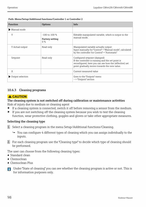
Operation Liquiline CM442R/CM444R/CM448R
98 Endress+Hauser
10.6.3 Cleaning programs
CAUTION!
The cleaning system is not switched off during calibration or maintenance activitiesRisk of injury due to medium or cleaning agent‣ If a cleaning system is connected, switch it off before removing a sensor from the medium.‣ If you are not switching off the cleaning system because you wish to test the cleaning
function, wear protective clothing, goggles and gloves or take other appropriate measures.
Selecting the cleaning type
1. Select a cleaning program in the menu Setup/Additional functions/Cleaning.
You can configure 4 different types of cleaning which you can assign individually to the inputs.
2. For each cleaning program use the "Cleaning type" to decide which type of cleaning should be performed.
The user can choose from the following cleaning types:• Standard clean• Chemoclean• Chemoclean Plus
Under "State of cleaning" you can see whether the cleaning program is active or not. This is for information purposes only.
Manual mode
Y -100 to 100 %
Factory setting0 %
Editable manipulated variable, which is output in the manual mode.
Y Actual output Read only Manipulated variable actually output:Input manually for "Control" = "Manual mode", calculated by the controller for Control" = "Automatic"
Setpoint Read only Configured setpoint (damped)If the controller is running and the set point is reconfigured, here you can see how the (effective) set point gradually moves towards the new value.
X Current measured value
Output selection Goes to the "Outputs" menu--> "Outputs" section
Path: Menu/Setup/Additional functions/Controller 1 or Controller 2
Function Options Info

Liquiline CM442R/CM444R/CM448R Operation
Endress+Hauser 99
Standard cleaning
Standard cleaning involves cleaning a sensor with compressed air, for instance, as performed with the ion-selective sensor CAS40D (connection of the cleaning unit for CAS40D→ ä 33 ).
Defining the cleaning cycle → ä 102
Chemoclean
An example of the use of the "Chemoclean" function is the use of the CYR10 injector unit to clean pH glass sensors. (CYR10 connection → ä 34)
Path: Menu/Setup/Additional functions/Cleaning/Cleaning 1 ... 4/Standard clean
Function Options Info
Cleaning time 5 to 600 s
Factory setting10 s
Cleaning time... Cleaning duration
The cleaning duration and interval depend on the process and sensor. Determine the variables empirically or based on experience.
Path: Menu/Setup/Additional functions/Cleaning/Cleaning 1 ... 4/Chemoclean
Function Options Info
Cleaning time 0 to 900 s
Factory setting5 s
Cleaning duration
The cleaning duration, pre-rinse and post-rinse times and the interval depend on the process and sensor. Determine the variables empirically or based on experience.Prerinse time 0 to 900 s
Factory setting0 s
Postrinse time 0 to 900 s
Factory setting0 s

Operation Liquiline CM442R/CM444R/CM448R
100 Endress+Hauser
Chemoclean Plus
Use the "Chemoclean Plus" function for measuring cycles in aggressive media or for regular cleaning operations with acids, bases or special cleaners.
a0022102
Fig. 66: Layout of a measuring point with regular cleaning with acid and base01A
Compressed air connection for "Measure" assembly position Compressed air connection for "Service" assembly position Acid pump
BCD
Base pumpRinse chamber of assembly ("Service" position)Medium ("Measure" position)
Path: Menu/Setup/Additional functions/Cleaning/Cleaning 1 ... 4/Chemoclean Plus/ChemoCleanPlus setup
Function Options Info
Cleaning steps setup Table to create a time program
You define a maximum of 30 program steps which should be performed one after the other. For each step enter the duration [s] and the state (0="off", 1="on") of each relay or output. You can specify the number and name of the outputs further down in the menu.See below for program examples.
Failsafe step setup Table view In the table specify the states that the relays or outputs should assume in the event of an error.
Limit contacts 0 to 2 Select the number of digital input signals (e.g. from limit position switches of the retractable assembly).
Limit contact 1 ... 2 Options• Binary inputs• Fieldbus signals
Define the signal source for each limit position switch.
Outputs 0 to 4 Select the number of outputs that actuators, such as valves or pumps, should activate.
CM44x / CM44xR / CSFxx
A
B
R1 R2 R3 R4 DI1 DI2
C
D
H O2
Air1
0
4R DIO

Liquiline CM442R/CM444R/CM448R Operation
Endress+Hauser 101
The pneumatic retractable assembly, e.g. CPA875, is activated by compressed air via a two-way valve. As a result, the assembly assumes either the position 0 ("Measure" - sensor in medium) or position 1 ("Service" - sensor in rinse chamber). Media such as water, acids or bases are supplied via valves or pumps. Here there are two states: 0 (= "off" or "closed") and 1 (= "on" or "open").
The hardware required for "Chemoclean Plus", such as control valves, pumps, compressed air supply, media etc., must be provided by the customer.
Output label 1 ... 4 Text You can assign a meaningful name to each output, e.g. "assembly", "acid", "base" etc.
Sample program: regular cleaning with acid and base
Limit switch Duration [s]
Assembly Water Acid Base
ES1 0 (Assembly in "Measure" position) 1 0 0 0 0
ES1 1 (Assembly in "Service" position) 5 1 0 0 0
ES1 1 10 1 1 0 0
ES1 1 2 1 1 1 0
ES1 1 10 1 1 0 0
ES1 1 2 1 1 0 1
ES1 1 10 1 1 0 0
ES1 1 2 1 0 0 0
ES1 0 5 0 0 0 0
Path: Menu/Setup/Additional functions/Cleaning/Cleaning 1 ... 4/Chemoclean Plus/ChemoCleanPlus setup
Function Options Info

Operation Liquiline CM442R/CM444R/CM448R
102 Endress+Hauser
Defining the cleaning cycle
Path: Menu/Setup/Additional functions/Cleaning/Cleaning 1 ... 4
Function Options Info
Cleaning cycle Options• Off• Interval• Weekly program
Factory settingOff
Choose from a cleaning routine that is restarted at set intervals and a user-definable weekly program.
Cleaning cycle= "Interval"
Cleaning interval 00-00:01 to 07-00:00 (DD-hh:mm)
Factory setting01-00:00
The interval value can be between 1 minute and 7 days.Example: You have set the value "01-00:00". Each day, the cleaning cycle starts at the same time you started the first cleaning cycle.
Cleaning cycle= "Weekly program"
Daily event times 00:00 to 23:59(HH:MM)
1. "Event time 1 to 6": Define up to 6 times.
You can then choose from these for each weekday afterwards.
2. For each day of the week, individually choose which of the 6 times is to be used for a cleaning routine on this particular day.
In this way you create weekly programs that are perfectly adapted to suit your process.
Weekdays Monday ... Sunday

Liquiline CM442R/CM444R/CM448R Operation
Endress+Hauser 103
Other settings and manual cleaning
Path: Menu/Setup/Additional functions/Cleaning/Cleaning 1 ... 4
Function Options Info
Start signal Options• Bus signals• Signals of digital or
analog inputs
Factory settingNone
In addition to cyclic cleaning, you can also use an input signal to start event-controlled cleaning.Choose the trigger for such a cleaning process here. Interval programs and weekly programs are executed as normal, i.e. conflicts can occur. Priority is given to the cleaning program that was the first to be started.
Hold Options• On• Off
Factory settingOn
Decide whether there should be a hold during the cleaning process. This hold affects the inputs to which this cleaning process is assigned.
Start single Action Start an individual cleaning process with the selected parameters.If cyclical cleaning is enabled, there are times in which it is not possible to manually start the process.
Manual mode Action You start the manual mode by acknowledging the warning. You can now start each possible cleaning step manually. If you want to return to cyclic cleaning, you must set "Manual mode" to "Off".
StoporStop Failsafe Action End the cleaning process (cyclically or manually)
Output selection Goes to the "Outputs" menuYou can assign the cleaning program directly to one or more outputs.--> "Outputs" section

Operation Liquiline CM442R/CM444R/CM448R
104 Endress+Hauser
10.6.4 Mathematical functions
In addition to "real" process values which are delivered by analog inputs or physical sensors connected to the device, you can also calculate a maximum of 6 "virtual" process values using mathematical functions.
The "virtual" process values can be:• Output via a current output or a fieldbus• Used as a controlled variable• Assigned as a measured variable to a limit contactor• Used as a measured variable to trigger cleaning• Displayed in user-defined measuring menus.
Difference
You can subtract the measured values of two sensors and use the result to detect incorrect measurements, for example.To calculate a difference, you must use two measured values with the same engineering unit.
Path: Menu/Setup/Additional functions/Mathematical functions/MF 1 to 6/Mode/Difference
Function Options Info
Calculation Options• Off• On
Factory settingOff
On/off switch for the function
Y1 The options depend on the sensors connected
Select the sensors and the measured variables that should be used as the minuend (Y1) or subtrahend (Y2).
Measured value
Y2
Measured value
Difference value Read only View this value in a user-defined measuring screen or output the value via the current output.
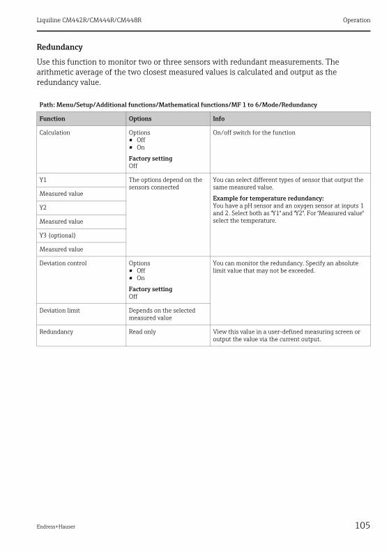
Liquiline CM442R/CM444R/CM448R Operation
Endress+Hauser 105
Redundancy
Use this function to monitor two or three sensors with redundant measurements. The arithmetic average of the two closest measured values is calculated and output as the redundancy value.
Path: Menu/Setup/Additional functions/Mathematical functions/MF 1 to 6/Mode/Redundancy
Function Options Info
Calculation Options• Off• On
Factory settingOff
On/off switch for the function
Y1 The options depend on the sensors connected
You can select different types of sensor that output the same measured value.
Example for temperature redundancy:You have a pH sensor and an oxygen sensor at inputs 1 and 2. Select both as "Y1" and "Y2". For "Measured value" select the temperature.
Measured value
Y2
Measured value
Y3 (optional)
Measured value
Deviation control Options• Off• On
Factory settingOff
You can monitor the redundancy. Specify an absolute limit value that may not be exceeded.
Deviation limit Depends on the selected measured value
Redundancy Read only View this value in a user-defined measuring screen or output the value via the current output.

Operation Liquiline CM442R/CM444R/CM448R
106 Endress+Hauser
rH value
To calculate the rH value, a pH sensor and an ORP sensor must be connected. It is irrelevant whether you are using a pH glass sensor, an ISFET sensor or the pH electrode of an ISE sensor.
Degassed conductivity
Carbon dioxide from the air can be a contributing factor to the conductivity of a medium. The degassed conductivity is the conductivity of the medium excluding the conductivity caused by carbon dioxide.
In the power station industry, for example, it is advantageous to use the degassed conductivity:• The percentage of conductivity caused by corrosion products or fouling in the feed water can
be determined as early as when the turbines are started. The system excludes the initially high conductivity values resulting from the ingress of air.
• If carbon dioxide is regarded as non-corrosive, the live steam can be directed to the turbine far earlier during startup.
• If the conductivity value increases during normal operation, it is possible to immediately determine an ingress of coolant or air by calculating the degassed conductivity.
Path: Menu/Setup/Additional functions/Mathematical functions/MF 1 to 6/Mode/rH calculation
Function Options Info
Calculation Options• Off• On
Factory settingOff
On/off switch for the function
pH source Connected pH sensor Set the input for the pH sensor and the input for the ORP sensor. Measured value interrogation is obsolete as you must select pH or ORP mV.ORP source Connected ORP sensor
Calculated rH Read only View this value in a user-defined measuring screen or output the value via the current output.
Path: Menu/Setup/Additional functions/Mathematical functions/MF 1 to 6/Mode/Degassed conductivity
Function Options Info
Calculation Options• Off• On
Factory settingOff
On/off switch for the function
Cation conductivity Connected conductivity sensor
"Cation conductivity" is the sensor downstream from the cation exchanger and upstream from the "degassing module", "Degassed conductivity" is the sensor at the outlet of the degassing module.Measured value interrogation is obsolete as you can only choose conductivity.
Degassed conductivity Connected conductivity sensor
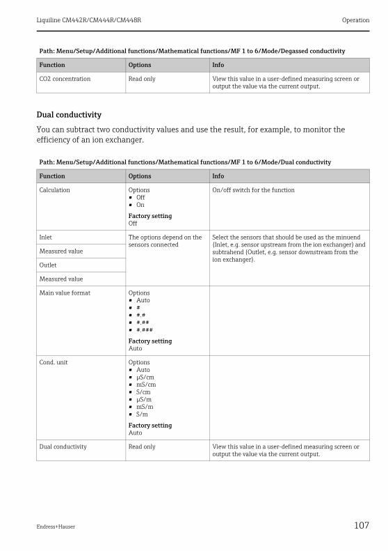
Liquiline CM442R/CM444R/CM448R Operation
Endress+Hauser 107
Dual conductivity
You can subtract two conductivity values and use the result, for example, to monitor the efficiency of an ion exchanger.
CO2 concentration Read only View this value in a user-defined measuring screen or output the value via the current output.
Path: Menu/Setup/Additional functions/Mathematical functions/MF 1 to 6/Mode/Dual conductivity
Function Options Info
Calculation Options• Off• On
Factory settingOff
On/off switch for the function
Inlet The options depend on the sensors connected
Select the sensors that should be used as the minuend (Inlet, e.g. sensor upstream from the ion exchanger) and subtrahend (Outlet, e.g. sensor downstream from the ion exchanger).
Measured value
Outlet
Measured value
Main value format Options• Auto• #• #.#• #.##• #.###
Factory settingAuto
Cond. unit Options• Auto• μS/cm• mS/cm• S/cm• μS/m• mS/m• S/m
Factory settingAuto
Dual conductivity Read only View this value in a user-defined measuring screen or output the value via the current output.
Path: Menu/Setup/Additional functions/Mathematical functions/MF 1 to 6/Mode/Degassed conductivity
Function Options Info

Operation Liquiline CM442R/CM444R/CM448R
108 Endress+Hauser
Calculated pH value
The pH value can be calculated from the measured values of two conductivity sensors under certain conditions. Areas of application include power stations, steam generators and boiler feedwater.
Path: Menu/Setup/Additional functions/Mathematical functions/MF 1 to 6/Mode/pH calculation from conductivity
Function Options Info
Calculation Options• Off• On
Factory settingOff
On/off switch for the function
Method Options• NaOH• NH3• LiOH
Factory settingNaOH
The calculation is performed on the basis of Guideline VGB-R-450L of the Technical Association of Large Power Plant Operators (Verband der Großkesselbetreiber, (VGB)).
NaOHpH = 11 + log {(κv - 1/3 κh)/273}NH3pH = 11 + log {(κv - 1/3 κh)/243}LiOHpH = 11 + log {(κv - 1/3 κh)/228}
κv ... "Inlet" ... direct conductivityκh ... "Outlet" ... acid conductivity
Inlet Choice of conductivity sensor
InletSensor upstream from the cation exchanger, "direct conductivity"OutletSensor downstream from the cation exchanger, "acid conductivity"The choice of measured value is obsolete since it must always be "Conductivity".
Outlet
Calculated pH Read only View this value in a user-defined measuring screen or output the value via the current output.
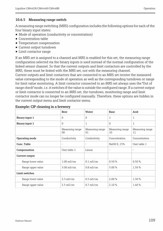
Liquiline CM442R/CM444R/CM448R Operation
Endress+Hauser 109
10.6.5 Measuring range switch
A measuring range switching (MRS) configuration includes the following options for each of the four binary input states:• Mode of operation (conductivity or concentration)• Concentration table• Temperature compensation• Current output turndown• Limit contactor range
If an MRS set is assigned to a channel and MRS is enabled for this set, the measuring range configuration selected via the binary inputs is used instead of the normal configuration of the linked sensor channel. So that the current outputs and limit contactors are controlled by the MRS, these must be linked with the MRS set, not with the measuring channel.Current outputs and limit contactors that are connected to an MRS set receive the measured value corresponding to the mode of operation as well as the corresponding turndown or range for limit value monitoring. A limit contactor connected to an MRS set always uses the "Out of range check" mode, i.e. it switches if the value is outside the configured range. If a current output or limit contactor is connected to an MRS set, the turndown, monitoring range and limit contactor mode can no longer be configured manually. Therefore, these options are hidden in the current output menu and limit contactor menu.
Example: CIP cleaning in a breweryBeer Water Base Acid
Binary input 1 0 0 1 1
Binary input 1 0 1 0 1
Measuring range 00
Measuring range 01
Measuring range 10
Measuring range 11
Operating mode Conductivity Conductivity Concentration Concentration
Conc. Table - - NaOH 0..15% User table 1
Compensation User table 1 Linear - -
Current output
Range lower value 1.00 mS/cm 0.1 mS/cm 0.50 % 0.50 %
Range upper value 3.00 mS/cm 0.8 mS/cm 5.00 % 1.50 %
Limit switches
Range lower value 2.3 mS/cm 0.5 mS/cm 2.00 % 1.30 %
Range upper value 2.5 mS/cm 0.7 mS/cm 2.10 % 1.40 %

Operation Liquiline CM442R/CM444R/CM448R
110 Endress+Hauser
Path: Menu/Setup/Additional functions/Measuring range switch
Function Options Info
MRS set 1MRS set 2
If you enter both activation codes, you have two independent parameter sets available for measuring range switching. The submenus are the same for both sets.
MRS Options• On• Off
Factory settingOff
Switches the function on or off
Sensor Options• None• Connected, inductive
conductivity sensors
Factory settingNone
This function can be used on conductivity sensors only.
Binary input 1 Options• None• Binary inputs• Fieldbus signals• Limit switch
Factory settingNone
Source of the switching signal, can be selected for input 1 and 2 in each case
Binary input 2
Sensor = conductivity sensor
Measuring range 00Measuring range 01Measuring range 10Measuring range 11
Select the MRSs; a maximum of 4 are possible.The submenus are identical for each and thus are displayed only once.
Operating mode Options• Conductivity• Concentration
Factory settingConductivity

Liquiline CM442R/CM444R/CM448R Operation
Endress+Hauser 111
Conc. Table Options• NaOH 0..15%• HCl 0..20%• HNO3 0..25%• HNO3 24..30%• H2SO4 0..28%• H2SO4 40..80%• H2SO4 93..100%• H3PO4 0..40%• NaCl 0..26%• User table 1• User table 2• User table 3• User table 4
Factory settingNaOH 0..15%
Concentration tables saved at the factory:NaOH: 0 to 15%, 0 to 100 ˚C (32 to 212 ˚F)HCl: 0 to 20%, 0 to 65 ˚C (32 to 149 ˚F)HNO3: 0 to 25%, 2 to 80 ˚C (36 to 176 ˚F)H2SO4: 0 to 28%, 0 to 100 ˚C (32 to 212 ˚F)H2SO4: 40 to 80%, 0 to 100 ˚C (32 to 212 ˚F)H2SO4: 93 to 100%, 0 to 100 ˚C (32 to 212 ˚F)H3PO4: 0 to 40%, 2 to 80 ˚C (36 to 176 ˚F)NaCl: 0 to 26%, 2 to 80 ˚C (36 to 176 ˚F)
Compensation Options• None• Linear• NaCl (IEC 746-3)• Water ISO7888 (20°C)• Water ISO7888 (25°C)• UPW NaCl• UPW HCl• User table 1• User table 2• User table 3• User table 4
Factory settingLinear
Various methods are available to compensate for the temperature dependency.Depending on your process, decide which type of compensation you want to use.Alternatively, you can also select "None" and thus measure uncompensated conductivity.
Current output
Range lower value 0 to 100 % Operating mode= "Concentration"
Range upper value
Range lower unit Options• S/m• μS/cm• mS/cm• S/cm• μS/m• mS/m
Factory settingmS/cm
Operating mode= "Conductivity"
Define the units and range limits for the output values.
Range lower value Enter value
Range upper unit Enter value
Range upper value Enter value
Path: Menu/Setup/Additional functions/Measuring range switch
Function Options Info
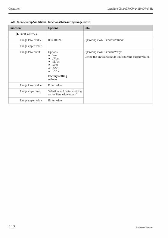
Operation Liquiline CM442R/CM444R/CM448R
112 Endress+Hauser
Limit switches
Range lower value 0 to 100 % Operating mode= "Concentration"
Range upper value
Range lower unit Options• S/m• μS/cm• mS/cm• S/cm• μS/m• mS/m
Factory settingmS/cm
Operating mode= "Conductivity"
Define the units and range limits for the output values.
Range lower value Enter value
Range upper unit Selection and factory setting as for "Range lower unit"
Range upper value Enter value
Path: Menu/Setup/Additional functions/Measuring range switch
Function Options Info

Liquiline CM442R/CM444R/CM448R Diagnostics and troubleshooting
Endress+Hauser 113
11 Diagnostics and troubleshootingThe color of the display background changes to red if a diagnostics message for error category "F" occurs.
11.1 General troubleshooting
11.1.1 Troubleshooting
A diagnostic message appears on the display or via the fieldbus, measured values are not plausible, or you identify a fault.
1. See the Diagnostics menu for the details on the diagnostic message.
Follow the instructions to rectify the problem.
2. If this does not help: Search for the diagnostic message under "Overview of diagnostic information" (→ ä 118) in this manual. Use the message number as a search criterion. Ignore the letters indicating the Namur error category.
Follow the troubleshooting instructions provided in the last column of the error tables.
3. If the measured values are implausible, the onsite display is faulty or you encounter other problems, search for the faults under "Process errors without messages" or "Device-specific errors".
Follow the recommended measures.
4. Contact the Service Department if you cannot rectify the error yourself. Only cite the error number.
11.1.2 Process errors without messages
See Operating Instructions for "Memosens", BA01245C
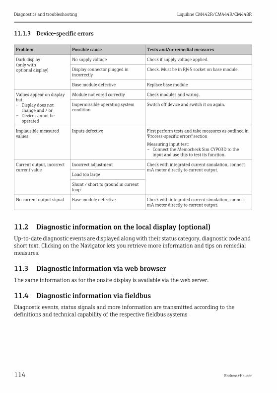
Diagnostics and troubleshooting Liquiline CM442R/CM444R/CM448R
114 Endress+Hauser
11.1.3 Device-specific errors
11.2 Diagnostic information on the local display (optional)Up-to-date diagnostic events are displayed along with their status category, diagnostic code and short text. Clicking on the Navigator lets you retrieve more information and tips on remedial measures.
11.3 Diagnostic information via web browserThe same information as for the onsite display is available via the web server.
11.4 Diagnostic information via fieldbusDiagnostic events, status signals and more information are transmitted according to the definitions and technical capability of the respective fieldbus systems
Problem Possible cause Tests and/or remedial measures
Dark display(only with optional display)
No supply voltage Check if supply voltage applied.
Display connector plugged in incorrectly
Check. Must be in RJ45 socket on base module.
Base module defective Replace base module
Values appear on display but:– Display does not
change and / or– Device cannot be
operated
Module not wired correctly Check modules and wiring.
Impermissible operating system condition
Switch off device and switch it on again.
Implausible measured values
Inputs defective First perform tests and take measures as outlined in "Process-specific errors" section
Measuring input test:– Connect the Memocheck Sim CYP03D to the
input and use this to test its function.
Current output, incorrect current value
Incorrect adjustment Check with integrated current simulation, connect mA meter directly to current output.
Load too large
Shunt / short to ground in current loop
No current output signal Base module defective Check with integrated current simulation, connect mA meter directly to current output.
Liquiline CM442R/CM444R/CM448R Diagnostics and troubleshooting
Endress+Hauser 115
11.5 Adjusting diagnostic information
11.5.1 Classification of diagnostics messages
More detailed information on the current diagnostics messages displayed is provided in the DIAG/Diagnostics list menu.
In accordance with Namur specification NE 107, the diagnostics messages are characterized by:• Message number• Error category (letter in front of the message number)
– F = (Failure) a malfunction has been detected– M = (Maintenance required) Action should be taken as soon as possible– C = (Function check) (No error)
Maintenance work is being performed on the device. Wait until the work has been completed.
– S = (Out of specification) The measuring point is being operated outside its specificationOperation is still possible. However, you run the risk of increased wear, shorter operating life or lower accuracy levels. The cause of the problem is to be found outside the measuring point.
• Message text
If you contact the Service Department, please cite the message number only. Since you can individually change the assignment of an error to an error category, the Service Department cannot use this information.

Diagnostics and troubleshooting Liquiline CM442R/CM444R/CM448R
116 Endress+Hauser
11.5.2 Adjusting diagnostic behavior
All the diagnostics messages are assigned to specific error categories at the factory. Since other settings might be preferred depending on the application, error categories and the effect errors have on the measuring point can be configured individually. Furthermore, every diagnostics message can be disabled.
ExampleThe controller returns diagnostics message 531 "Logbook full". You want to change this message so that an error is not indicated on the display for example.1. Go to:
– Menu/Setup/General settings/Extended setup/Diagnostics/Device behaviorfor device-specific diagnostics messages (as in this example)
– Menu/Setup/Inputs/<sensor type>/Extended setup/Diagnostics settings/Diag. behaviorfor sensor-specific diagnostics messages.
2. Select the diagnostics message and press the navigator button.3. Decide:
a. Should the message be deactivated?b. Do you want to change the error category?c. Should an error current be output?d. Do you want to trigger a cleaning program?
4. Deactivate the message, for example (Diagnostics message to "Off").
Configuration options
The list of diagnostic messages displayed depends on the path selected. There are device-specific messages, and messages that depend on what sensor is connected.
Path: ... /Extended setup/Diagnostics settings/Diag. behavior
Function Options Info
List of diagnostic messages Select the message to be changed. Only then can you make the settings for this message.
Diag. code Read only
Diagnostic message Options• On• Off
Factory settingDepends on the message
You can deactivate or reactivate a diagnostics message here.
Deactivating means:• No error message in the measuring mode• No error current at the current output
Error current Options• On• Off
Factory settingDepends on the message
Decide whether an error current should be output at the current output if the diagnostic message display is activated.

Liquiline CM442R/CM444R/CM448R Diagnostics and troubleshooting
Endress+Hauser 117
Status signal Options• Maintenance (M)• Out of specification (S)• Function check (C)• Failure (F)
Factory settingDepends on the message
The messages are divided into different error categories in accordance with NAMUR NE 107.
Decide whether you want to change a status signal assignment for your application.
Diag. output Options• None
Factory settingNone
Before you can assign the message to an output, you must first configure a relay output to "Diagnostics" (Menu/Setup/Outputs, assign the "Diagnostics" function and set the Operating mode to "as assigned").
Cleaning program (for sensors)
Options• None• Cleaning 1• Cleaning 2• Cleaning 3• Cleaning 4
Factory settingNone
Decide whether the diagnostic message should trigger a cleaning program.You can define the cleaning programs under:Menu/Setup/Additional functions/Cleaning.
Detail information Read only Here you can find more information on the diagnostic message and instructions on how to resolve the problem.
Path: ... /Extended setup/Diagnostics settings/Diag. behavior
Function Options Info
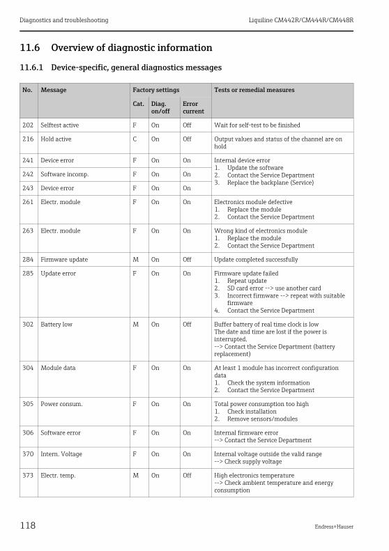
Diagnostics and troubleshooting Liquiline CM442R/CM444R/CM448R
118 Endress+Hauser
11.6 Overview of diagnostic information
11.6.1 Device-specific, general diagnostics messages
No. Message Factory settings Tests or remedial measures
Cat. Diag. on/off
Error current
202 Selftest active F On Off Wait for self-test to be finished
216 Hold active C On Off Output values and status of the channel are on hold
241 Device error F On On Internal device error1. Update the software2. Contact the Service Department3. Replace the backplane (Service)
242 Software incomp. F On On
243 Device error F On On
261 Electr. module F On On Electronics module defective1. Replace the module2. Contact the Service Department
263 Electr. module F On On Wrong kind of electronics module1. Replace the module2. Contact the Service Department
284 Firmware update M On Off Update completed successfully
285 Update error F On On Firmware update failed1. Repeat update2. SD card error --> use another card3. Incorrect firmware --> repeat with suitable
firmware4. Contact the Service Department
302 Battery low M On Off Buffer battery of real time clock is lowThe date and time are lost if the power is interrupted.--> Contact the Service Department (battery replacement)
304 Module data F On On At least 1 module has incorrect configuration data1. Check the system information2. Contact the Service Department
305 Power consum. F On On Total power consumption too high1. Check installation2. Remove sensors/modules
306 Software error F On On Internal firmware error--> Contact the Service Department
370 Intern. Voltage F On On Internal voltage outside the valid range--> Check supply voltage
373 Electr. temp. M On Off High electronics temperature--> Check ambient temperature and energy consumption
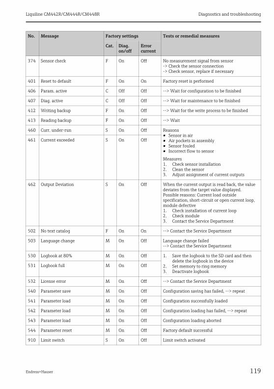
Liquiline CM442R/CM444R/CM448R Diagnostics and troubleshooting
Endress+Hauser 119
374 Sensor check F On Off No measurement signal from sensor-> Check the sensor connection-> Check sensor, replace if necessary
401 Reset to default F On On Factory reset is performed
406 Param. active C Off Off --> Wait for configuration to be finished
407 Diag. active C Off Off --> Wait for maintenance to be finished
412 Writing backup F On Off --> Wait for the write process to be finished
413 Reading backup F On Off --> Wait
460 Curr. under-run S On Off Reasons• Sensor in air• Air pockets in assembly• Sensor fouled• Incorrect flow to sensor
Measures1. Check sensor installation2. Clean the sensor3. Adjust assignment of current outputs
461 Current exceeded S On Off
462 Output Deviation S On Off When the current output is read back, the value deviates from the target value displayed.Possible reasons: Current load outside specification, short-circuit or open current loop, module defective1. Check installation of current loop2. Check module3. Contact the Service Department
502 No text catalog F On On --> Contact the Service Department
503 Language change M On Off Language change failed--> Contact the Service Department
530 Logbook at 80% M On Off 1. Save the logbook to the SD card and then delete the logbook in the device
2. Set memory to ring memory3. Deactivate logbook
531 Logbook full M On Off
532 License error M On Off --> Contact the Service Department
540 Parameter save M On Off Configuration saving has failed, --> repeat
541 Parameter load M On Off Configuration successfully loaded
542 Parameter load M On Off Configuration loading has failed, --> repeat
543 Parameter load M On Off Configuration loading aborted
544 Parameter reset M On Off Factory default successful
910 Limit switch S On Off Limit switch activated
No. Message Factory settings Tests or remedial measures
Cat. Diag. on/off
Error current
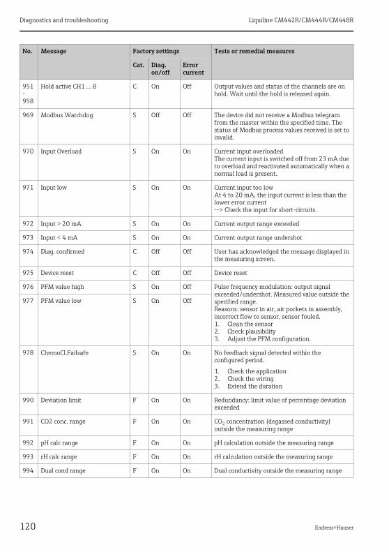
Diagnostics and troubleshooting Liquiline CM442R/CM444R/CM448R
120 Endress+Hauser
951- 958
Hold active CH1 ... 8 C On Off Output values and status of the channels are on hold. Wait until the hold is released again.
969 Modbus Watchdog S Off Off The device did not receive a Modbus telegram from the master within the specified time. The status of Modbus process values received is set to invalid.
970 Input Overload S On On Current input overloadedThe current input is switched off from 23 mA due to overload and reactivated automatically when a normal load is present.
971 Input low S On On Current input too lowAt 4 to 20 mA, the input current is less than the lower error current--> Check the input for short-circuits.
972 Input > 20 mA S On On Current output range exceeded
973 Input < 4 mA S On On Current output range undershot
974 Diag. confirmed C Off Off User has acknowledged the message displayed in the measuring screen.
975 Device reset C Off Off Device reset
976 PFM value high S On Off Pulse frequency modulation: output signal exceeded/undershot. Measured value outside the specified range.Reasons: sensor in air, air pockets in assembly, incorrect flow to sensor, sensor fouled.1. Clean the sensor2. Check plausibility3. Adjust the PFM configuration.
977 PFM value low S On Off
978 ChemoCl.Failsafe S On On No feedback signal detected within the configured period.
1. Check the application2. Check the wiring3. Extend the duration
990 Deviation limit F On On Redundancy: limit value of percentage deviation exceeded
991 CO2 conc. range F On On CO2 concentration (degassed conductivity) outside the measuring range
992 pH calc range F On On pH calculation outside the measuring range
993 rH calc range F On On rH calculation outside the measuring range
994 Dual cond range F On On Dual conductivity outside the measuring range
No. Message Factory settings Tests or remedial measures
Cat. Diag. on/off
Error current

Liquiline CM442R/CM444R/CM448R Diagnostics and troubleshooting
Endress+Hauser 121
11.6.2 Sensor-specific diagnostics messages
See Operating Instructions for "Memosens", BA01245C
11.7 Pending diagnostic messagesThe Diagnostics menu contains all the information on the device status.Furthermore, various service functions are available.
The following messages are directly displayed every time you enter the menu:• "Most important message"
Diagnostics message recorded with the highest criticality level• "Past message"
Diagnostic message whose cause is no longer present.
All the other functions in the Diagnostics menu are described in the following chapters.
11.8 Diagnostics listAll the current diagnostics messages are listed here.A time stamp is available for each message. Furthermore, the system also displays the configuration and description of the message as saved in "Menu/Setup/General settings/Diagnostics/Device behavior".
11.9 Event logbook
11.9.1 Available logbooks
Types of logbooks• Logbooks physically available (all apart from the overall logbook)• Database view of all logbooks (=overall logbook)
Logbook Visible in Max. entries
Can be disabled1)
Logbook can be deleted
Entries can be deleted
Can be exported
Overall logbook All events 1000 Yes No Yes No
Calibration logbook Calibration events 75 (Yes) No Yes Yes
Operation logbook Configuration events 250 (Yes) No Yes Yes
Diagnostics logbook Diagnostic events 250 (Yes) No Yes Yes
Version logbook All events 50 No No No Yes
Hardware version logbook
All events 125 No No No Yes
Data logbook for sensors (optional)
Data logbooks 150,000 Yes Yes Yes Yes

Diagnostics and troubleshooting Liquiline CM442R/CM444R/CM448R
122 Endress+Hauser
11.9.2 Logbooks menu
Debugging logbook Only accessible with the special activation code (Service)
1000 Yes No Yes Yes
1) Data in brackets means this depends on the overall logbook
Diagnostics/Logbooks
Function Options Info
All events Chronological list of all the logbook entries, with information on the type of event.
Show Events are displayed Select a particular event to display more detailed information.
Go to date User input• Go to date• Time
Use this function to go directly to a specific time in the list. In this way, you avoid having to scroll through all the information. The complete list is always visible, however.
Calibration events Chronological list of the calibration events.
Show Events are displayed Select a particular event to display more detailed information.
Go to date User input• Go to date• Time
Use this function to go directly to a specific time in the list. In this way, you avoid having to scroll through all the information. The complete list is always visible, however.
Delete all entries Action You can delete all the calibration logbook entries here.
Configuration events Chronological list of the configuration events.
Show Events are displayed Select a particular event to display more detailed information.
Go to date User input• Go to date• Time
Use this function to go directly to a specific time in the list. In this way, you avoid having to scroll through all the information. The complete list is always visible, however.
Delete all entries Action You can use this to delete all the operation logbook entries.
Diagnostic events Chronological list of the diagnostics events.
Show Events are displayed Select a particular event to display more detailed information.
Logbook Visible in Max. entries
Can be disabled1)
Logbook can be deleted
Entries can be deleted
Can be exported
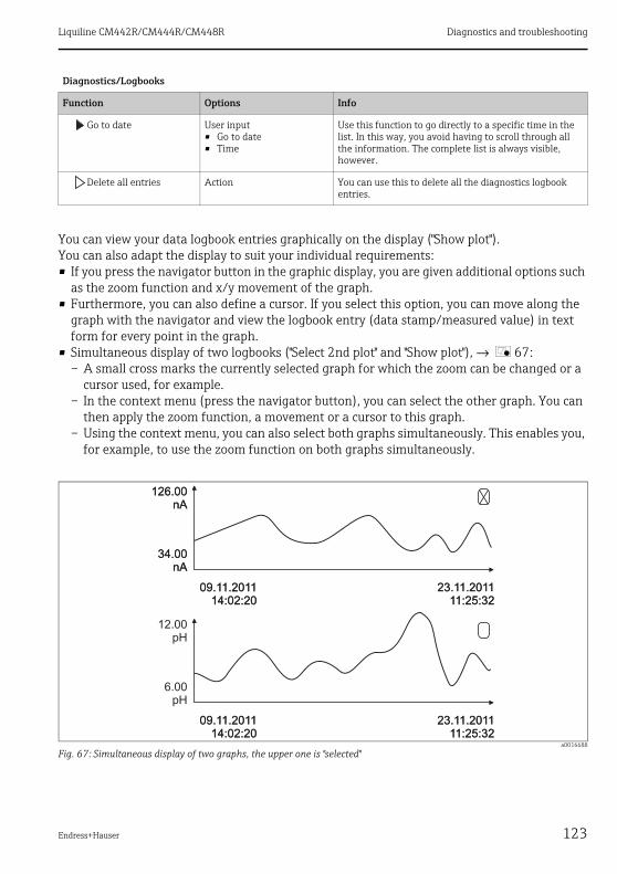
Liquiline CM442R/CM444R/CM448R Diagnostics and troubleshooting
Endress+Hauser 123
You can view your data logbook entries graphically on the display ("Show plot").You can also adapt the display to suit your individual requirements:• If you press the navigator button in the graphic display, you are given additional options such
as the zoom function and x/y movement of the graph.• Furthermore, you can also define a cursor. If you select this option, you can move along the
graph with the navigator and view the logbook entry (data stamp/measured value) in text form for every point in the graph.
• Simultaneous display of two logbooks ("Select 2nd plot" and "Show plot"), → å 67:– A small cross marks the currently selected graph for which the zoom can be changed or a
cursor used, for example.– In the context menu (press the navigator button), you can select the other graph. You can
then apply the zoom function, a movement or a cursor to this graph.– Using the context menu, you can also select both graphs simultaneously. This enables you,
for example, to use the zoom function on both graphs simultaneously.
a0016688
Fig. 67: Simultaneous display of two graphs, the upper one is "selected"
Go to date User input• Go to date• Time
Use this function to go directly to a specific time in the list. In this way, you avoid having to scroll through all the information. The complete list is always visible, however.
Delete all entries Action You can use this to delete all the diagnostics logbook entries.
Diagnostics/Logbooks
Function Options Info
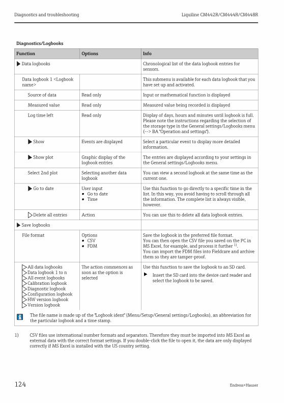
Diagnostics and troubleshooting Liquiline CM442R/CM444R/CM448R
124 Endress+Hauser
Diagnostics/Logbooks
Function Options Info
Data logbooks Chronological list of the data logbook entries for sensors.
Data logbook 1 <Logbook name>
This submenu is available for each data logbook that you have set up and activated.
Source of data Read only Input or mathematical function is displayed
Measured value Read only Measured value being recorded is displayed
Log time left Read only Display of days, hours and minutes until logbook is full. Please note the instructions regarding the selection of the storage type in the General settings/Logbooks menu (--> BA "Operation and settings").
Show Events are displayed Select a particular event to display more detailed information.
Show plot Graphic display of the logbook entries
The entries are displayed according to your settings in the General settings/Logbooks menu.
Select 2nd plot Selecting another data logbook
You can view a second logbook at the same time as the current one.
Go to date User input• Go to date• Time
Use this function to go directly to a specific time in the list. In this way, you avoid having to scroll through all the information. The complete list is always visible, however.
Delete all entries Action You can use this to delete all data logbook entries.
Save logbooks
File format Options• CSV• FDM
Save the logbook in the preferred file format.You can then open the CSV file you saved on the PC in MS Excel, for example, and process it further 1).You can import the FDM files into Fieldcare and archive them so they are tamper-proof.
1) CSV files use international number formats and separators. Therefore they must be imported into MS Excel as external data with the correct format settings. If you double-click the file to open it, the data are only displayed correctly if MS Excel is installed with the US country setting.
All data logbooksData logbook 1 to nAll event logbooksCalibration logbookDiagnostic logbookConfiguration logbookHW version logbookVersion logbook
The action commences as soon as the option is selected
Use this function to save the logbook to an SD card.
‣ Insert the SD card into the device card reader and select the logbook to be saved.
The file name is made up of the "Logbook ident" (Menu/Setup/General settings/Logbooks), an abbreviation for the particular logbook and a time stamp.
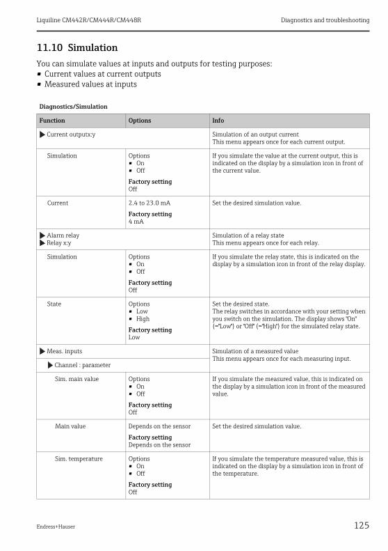
Liquiline CM442R/CM444R/CM448R Diagnostics and troubleshooting
Endress+Hauser 125
11.10 SimulationYou can simulate values at inputs and outputs for testing purposes:• Current values at current outputs• Measured values at inputs
Diagnostics/Simulation
Function Options Info
Current outputx:y Simulation of an output currentThis menu appears once for each current output.
Simulation Options• On• Off
Factory settingOff
If you simulate the value at the current output, this is indicated on the display by a simulation icon in front of the current value.
Current 2.4 to 23.0 mA
Factory setting4 mA
Set the desired simulation value.
Alarm relayRelay x:y
Simulation of a relay stateThis menu appears once for each relay.
Simulation Options• On• Off
Factory settingOff
If you simulate the relay state, this is indicated on the display by a simulation icon in front of the relay display.
State Options• Low• High
Factory settingLow
Set the desired state.The relay switches in accordance with your setting when you switch on the simulation. The display shows "On" (="Low") or "Off" (="High") for the simulated relay state.
Meas. inputs Simulation of a measured value This menu appears once for each measuring input.
Channel : parameter
Sim. main value Options• On• Off
Factory settingOff
If you simulate the measured value, this is indicated on the display by a simulation icon in front of the measured value.
Main value Depends on the sensor
Factory settingDepends on the sensor
Set the desired simulation value.
Sim. temperature Options• On• Off
Factory settingOff
If you simulate the temperature measured value, this is indicated on the display by a simulation icon in front of the temperature.

Diagnostics and troubleshooting Liquiline CM442R/CM444R/CM448R
126 Endress+Hauser
11.11 Reset measuring instrument
Temperature -50.0 to +250.0 ˚C(-58.0 to 482.0 ˚F)
Factory setting20.0 ˚C (68.0 ˚F)
Set the desired simulation value.
Diagnostics/Systemtest/Reset
Function Options Info
Device reset Options• OK• ESC
Restart and keep all the settings
Factory default Options• OK• ESC
Restart with factory settingsSettings that have not been saved are lost.
Power supply Read only• Digital Supply 1: 1.2V• Digital Supply 2: 3.3V• Analog Supply: 12.5V• Sensor Supply: 24V• Temperature
Detailed list of power supply to instrument.
The actual values can vary without a malfunction being present.
Diagnostics/Simulation
Function Options Info
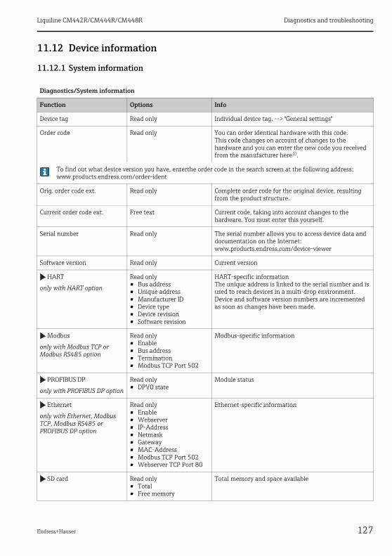
Liquiline CM442R/CM444R/CM448R Diagnostics and troubleshooting
Endress+Hauser 127
11.12 Device information
11.12.1 System information
Diagnostics/System information
Function Options Info
Device tag Read only Individual device tag, --> "General settings"
Order code Read only You can order identical hardware with this code.This code changes on account of changes to the hardware and you can enter the new code you received from the manufacturer here1).
To find out what device version you have, enterthe order code in the search screen at the following address: www.products.endress.com/order-ident
Orig. order code ext. Read only Complete order code for the original device, resulting from the product structure.
Current order code ext. Free text Current code, taking into account changes to the hardware. You must enter this yourself.
Serial number Read only The serial number allows you to access device data and documentation on the Internet:www.products.endress.com/device-viewer
Software version Read only Current version
HART
only with HART option
Read only• Bus address• Unique address• Manufacturer ID• Device type• Device revision• Software revision
HART-specific informationThe unique address is linked to the serial number and is used to reach devices in a multi-drop environment.Device and software version numbers are incremented as soon as changes have been made.
Modbus
only with Modbus TCP or Modbus RS485 option
Read only• Enable• Bus address• Termination• Modbus TCP Port 502
Modbus-specific information
PROFIBUS DP
only with PROFIBUS DP option
Read only• DPV0 state
Module status
Ethernet
only with Ethernet, Modbus TCP, Modbus RS485 or PROFIBUS DP option
Read only• Enable• Webserver• IP-Address• Netmask• Gateway• MAC-Address• Modbus TCP Port 502• Webserver TCP Port 80
Ethernet-specific information
SD card Read only• Total• Free memory
Total memory and space available
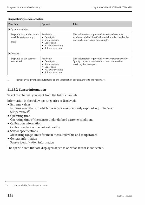
Diagnostics and troubleshooting Liquiline CM442R/CM444R/CM448R
128 Endress+Hauser
11.12.2 Sensor information
Select the channel you want from the list of channels.
Information in the following categories is displayed:• Extreme values
Extreme conditions to which the sensor was previously exposed, e.g. min./max. temperatures2)
• Operating timeOperating time of the sensor under defined extreme conditions
• Calibration informationCalibration data of the last calibration
• Sensor specificationsMeasuring range limits for main measured value and temperature
• General informationSensor identification information
The specific data that are displayed depends on what sensor is connected.
System modules
Depends on the electronics module available, e.g.:
Base
Read only• Description• Serial number• Order code• Hardware version• Software version
This information is provided for every electronics module available. Specify the serial numbers and order codes when servicing, for example.
Sensors
Depends on the sensors connected
Read only• Description• Serial number• Order code• Hardware version• Software version
This information is provided for every sensor available. Specify the serial numbers and order codes when servicing, for example.
1) Provided you give the manufacturer all the information about changes to the hardware.
2) Not available for all sensor types.
Diagnostics/System information
Function Options Info
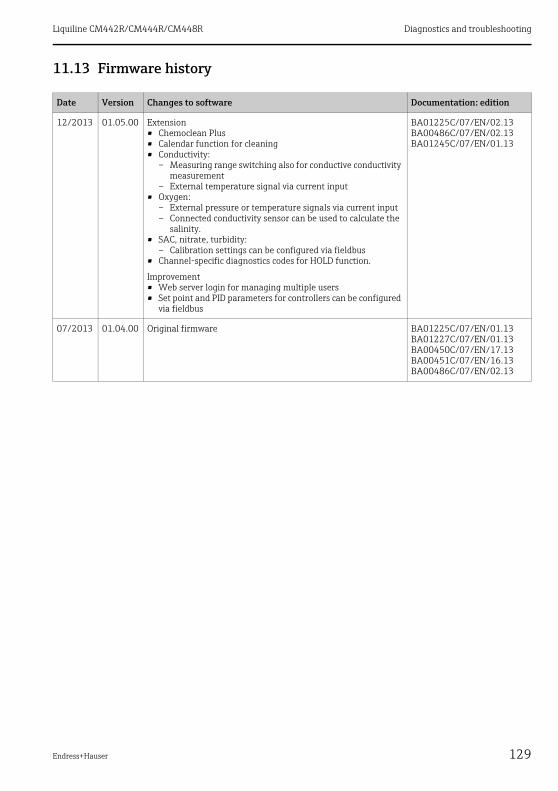
Liquiline CM442R/CM444R/CM448R Diagnostics and troubleshooting
Endress+Hauser 129
11.13 Firmware history
Date Version Changes to software Documentation: edition
12/2013 01.05.00 Extension• Chemoclean Plus• Calendar function for cleaning• Conductivity:
– Measuring range switching also for conductive conductivity measurement
– External temperature signal via current input• Oxygen:
– External pressure or temperature signals via current input– Connected conductivity sensor can be used to calculate the
salinity.• SAC, nitrate, turbidity:
– Calibration settings can be configured via fieldbus• Channel-specific diagnostics codes for HOLD function.
Improvement• Web server login for managing multiple users• Set point and PID parameters for controllers can be configured
via fieldbus
BA01225C/07/EN/02.13BA00486C/07/EN/02.13BA01245C/07/EN/01.13
07/2013 01.04.00 Original firmware BA01225C/07/EN/01.13BA01227C/07/EN/01.13BA00450C/07/EN/17.13BA00451C/07/EN/16.13BA00486C/07/EN/02.13
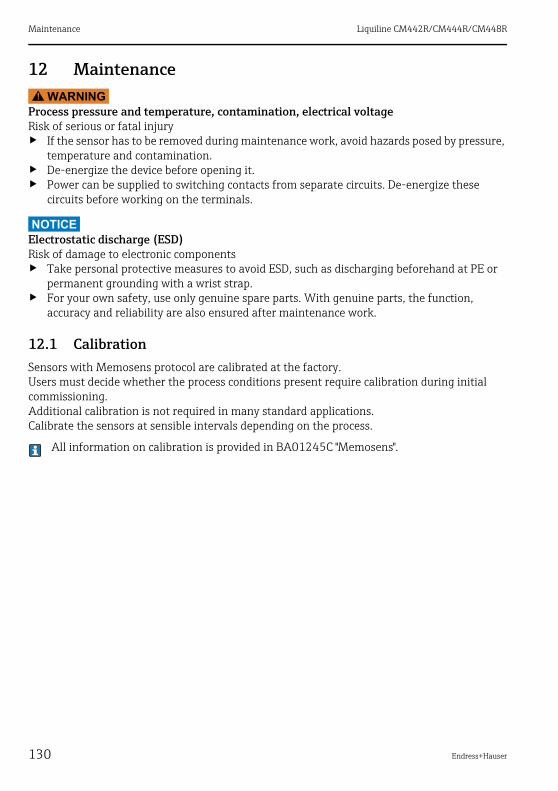
Maintenance Liquiline CM442R/CM444R/CM448R
130 Endress+Hauser
12 MaintenanceWARNING!
Process pressure and temperature, contamination, electrical voltageRisk of serious or fatal injury‣ If the sensor has to be removed during maintenance work, avoid hazards posed by pressure,
temperature and contamination.‣ De-energize the device before opening it.‣ Power can be supplied to switching contacts from separate circuits. De-energize these
circuits before working on the terminals.
NOTICEElectrostatic discharge (ESD)Risk of damage to electronic components‣ Take personal protective measures to avoid ESD, such as discharging beforehand at PE or
permanent grounding with a wrist strap.‣ For your own safety, use only genuine spare parts. With genuine parts, the function,
accuracy and reliability are also ensured after maintenance work.
12.1 CalibrationSensors with Memosens protocol are calibrated at the factory.Users must decide whether the process conditions present require calibration during initial commissioning.Additional calibration is not required in many standard applications.Calibrate the sensors at sensible intervals depending on the process.
All information on calibration is provided in BA01245C "Memosens".

Liquiline CM442R/CM444R/CM448R Maintenance
Endress+Hauser 131
12.2 Cleaning
12.2.1 External display (in installed state)
Only clean the front of the housing with commercially available cleaning agents.
The front is resistant to the following as per DIN 42 115:• Ethanol (short periods)• Diluted acids (max. 2% HCl)• Diluted bases (max. 3% NaOH)• Soap-based household cleaners
NOTICEProhibited cleaning agentsDamage to the housing surface or housing seal‣ For cleaning purposes, never use concentrated mineral acids or bases.‣ Never use organic cleaners such as benzyl alcohol, methanol, methylene chloride, xylene or
concentrated glycerol cleaner.‣ Never use high-pressure steam for cleaning purposes.
12.2.2 Digital sensors
CAUTION!
The cleaning system is not switched off during calibration or maintenance activitiesRisk of injury due to medium or cleaning agent‣ If a cleaning system is connected, switch it off before removing a sensor from the medium.‣ If you are not switching off the cleaning system because you wish to test the cleaning
function, wear protective clothing, goggles and gloves or take other appropriate measures.
1. If an error occurs or the maintenance schedule stipulates that the sensor has to be replaced, use a new sensor or a sensor that has been precalibrated in the laboratory.A sensor is calibrated in the laboratory under optimum external conditions, thereby ensuring better quality of measurement.
2. Remove the sensor to be serviced and install the new sensor.3. You must perform calibration if you use a sensor that is not precalibrated.4. The sensor data are automatically accepted by the transmitter. A release code is not
required.5. Measurement is resumed.6. Take the used sensor back to the laboratory. In the laboratory you can get the sensor ready
for reuse while ensuring the availability of the measuring point.– Clean the sensor. For this purpose, use the cleaning agent specified in the sensor
manual.– Inspect the sensor for cracks or other damage.– If no damage is found, regenerate the sensor. Where necessary, store the sensor in a
regeneration solution (--> sensor manual).– Recalibrate the sensor for reuse.

Maintenance Liquiline CM442R/CM444R/CM448R
132 Endress+Hauser
12.2.3 Assemblies
Refer to the assembly operating manual for information on servicing and troubleshooting the assembly. The assembly operating manual describes the procedure for mounting and disassembling the assembly, replacing the sensors and seals, and contains information on the material resistance properties, as well as spare parts and accessories.
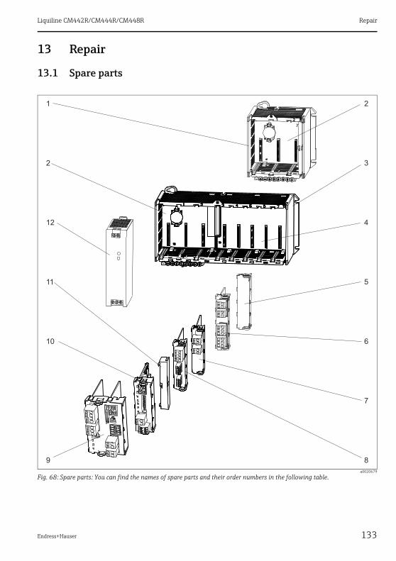
Liquiline CM442R/CM444R/CM448R Repair
Endress+Hauser 133
13 Repair
13.1 Spare parts
a0020679
Fig. 68: Spare parts: You can find the names of spare parts and their order numbers in the following table.

Repair Liquiline CM442R/CM444R/CM448R
134 Endress+Hauser
NOTICEDamaged cables from careless maintenance or repair work‣ Exercise care when replacing defective cables, particularly if you are removing them from a
cable duct.‣ Preferably use a junction box, which then acts as a stationary connection into the cabinet.
Item Kit CM44x Order number
1 Kit CM442R• Control cabinet installation housing, complete
71222273
2 Kit CM44x/CM44xR: electronics module backplane• Backplane complete• To be replaced only by Endress+Hauser Service
71101457
3 Kit CM444R/448R• Control cabinet installation housing, complete
71222276
4 Kit CM44x/CM44xR: electronics module extension backplane• Extension backplane complete• To be replaced only by Endress+Hauser Service
71141366
5, 11 Kit CM44xR• Set of covers for shock protection
71222282
9 Kit CM442: base module BASE-L 24V AC/DC• Base module 24V AC/DC complete• End cover (item 8)• Instructions for spare parts kit CM44x
71100607
Kit CM442: base module BASE-H 230V AC• Base module 230V AC, complete• End cover (item 8)• Instructions for spare parts kit CM44x
71100611
Kit CM444/CM448: base module BASE-E• Base module, complete• End cover (item 8)• Connecting cable to connect to the power unit• Instructions for spare parts kit CM44x
71141336
Kit CM44x: terminal set, base module 71107452

Liquiline CM442R/CM444R/CM448R Repair
Endress+Hauser 135
6, 7, 8, 10 Kit CM44x/ CM44xR: extension module AOR (2 relays + 2 current outputs)• Extension module AOR, complete• Instructions for spare parts kit CM44x
71111053
Kit CM44x/CM44xR: terminal set, extension module AOR 71107453
Kit CM44x/CM44xR: extension module 2R (2 relays)• Extension module 2R complete• Instructions for spare parts kit CM44x
71125375
Kit CM44x/CM44xR: extension module 4R (4 relays)• Extension module 4R complete• Instructions for spare parts kit CM44x
71125376
Kit CM44x/CM44xR: terminal set, extension module 2R, 4R 71155581
Kit CM44x/CM44xR: extension module 2AO (2 x 0/4 to 20 mA)• Extension module 2AO complete• Instructions for spare parts kit CM44x
71135632
Kit CM44x/CM44xR: extension module 4AO (4 x 0/4 to 20 mA)• Extension module 4AO complete• Instructions for spare parts kit CM44x
71135633
Kit CM44x/CM44xR: terminal set, extension module 2AO, 4AO 71155582
Kit CM44x/CM44xR: extension module DIO (2 x digital input, digital output in each case)• Extension module DIO, complete• Instructions for CM44x/CM44xR spare parts kits
71135638
Kit CM44x/CM44xR: terminal set, extension module DIO 71219784
Kit CM44x/CM44xR: extension module 2DS (2 x digital sensor)• Extension module 2DS complete• Instructions for spare parts kit CM44x
71135631
Kit CM44x/CM44xR: extension module 2AI (2 x analog input 0/4 to 20 mA)• Extension module 2AI complete• Instructions for spare parts kit CM44x
71135639
Kit CM44x/CM44xR: extension module 485 (Ethernet configuration)• Extension module 485 complete• With activation code extendable to PROFIBUS DP or Modbus RS 485 or
Modbus TCP or EtherNet/IP• Instructions for spare parts kit CM44x
71135634
Kit CM44x/CM44xR: terminal set for extension module 2AI, 485 71155583
12 Kit CM444R/8R: DIN rail power unit• DIN rail power unit 110 to 230 VAC• DIN rail power unit 24 VDC
• 71222277• 71222279
Item Kit CM44x Order number
Repair Liquiline CM442R/CM444R/CM448R
136 Endress+Hauser
13.2 ReturnThe product has to be returned in the event of repair, factory calibration, incorrect delivery or incorrect ordering. As an ISO-certified company and due to legal regulations, Endress+Hauser is obligated to use particular handling techniques for all returned products that have come into contact with a medium.
In order to ensure a reliable, proper and quick return:Learn about the methods and basic conditions at the Internet sitewww.services.endress.com/return-material
13.3 DisposalThe device contains electronic components and must therefore be disposed of in accordance with regulations on the disposal of electronic waste.Please observe local regulations.
The battery located on the backplane must be disposed of in accordance with local regulations governing the disposal of batteries.

Liquiline CM442R/CM444R/CM448R Accessories
Endress+Hauser 137
14 AccessoriesThe most important accessories available at the time this document went to print are listed below. Contact your service representative or Sales Center for accessories that are not listed here.
14.1 Measuring cableMemosens data cable CYK10• For digital sensors with Memosens technology
pH, redox, oxygen (amperometric), chlorine, conductivity (conductive)• Order as per product structure (--> Online Configurator, www.products.endress.com/cyk10)• Technical Information TI00118C/07/EN
Memosens data cable CYK11• Extension cable for digital sensors with Memosens protocol• Order as per product structure (--> Online Configurator, www.products.endress.com/cyk11)
Measuring cable CYK81• Unterminated cable for extending sensor cables (e.g. Memosens)• 2 x 2 cores, twisted with shielding and PVC sheath (2 x 2 x 0.5 mm2 + shielding)• Material sold by the meter, Order No.: 51502543
Accessories Liquiline CM442R/CM444R/CM448R
138 Endress+Hauser
14.2 Sensors
14.2.1 Glass electrodes
Orbisint CPS11D• pH sensor with Memosens technology• Dirt-resistant PTFE diaphragm• Order as per product structure (--> Online Configurator, www.products.endress.com/cps11d)• Technical Information TI00028C/07/EN
Memosens CPS31D• pH sensor with Memosens technology• Gel-filled reference system with ceramic diaphragm• Order as per product structure (--> Online Configurator, www.products.endress.com/cps31d)• Technical Information TI00030C/07/EN
Ceraliquid CPS41D• pH sensor with Memosens technology• Ceramic diaphragm and KCl liquid electrolyte• Order as per product structure (--> Online Configurator, www.products.endress.com/cps41d)• Technical Information TI00079C/07/EN
Ceragel CPS71D• pH sensor with Memosens technology• Poison-resistant reference with ion trap• Order as per product structure (--> Online Configurator, www.products.endress.com/cps71d)• Technical Information TI00245C/07/EN
Orbipore CPS91D• pH sensor with Memosens technology• Open aperture junction for media with high potential for fouling• Order as per product structure (--> Online Configurator, www.products.endress.com/cps91d)• Technical Information TI00375C/07/EN
Orbipac CPF81D• pH compact sensor for installation or immersion operation in industrial water and wastewater• Order as per product structure (--> Online Configurator, www.products.endress.com/cpf81d)• Technical Information TI191C/07/EN
14.2.2 Enamel pH electrodes
Ceramax CPS341D• pH electrode with pH-sensitive enamel• For the toughest requirements in terms of precision, pressure, temperature, sterility and
operating life• Order as per product structure (--> Online Configurator,
www.products.endress.com/cps341d)• Technical Information TI00468C/07/EN

Liquiline CM442R/CM444R/CM448R Accessories
Endress+Hauser 139
14.2.3 ORP sensors
Orbisint CPS12D• ORP sensor with Memosens technology• Dirt-resistant PTFE diaphragm;• Order as per product structure (--> Online Configurator, www.products.endress.com/cps12d)• Technical Information TI367C/07/EN
Ceraliquid CPS42D• ORP sensor with Memosens technology• Ceramic diaphragm and KCl liquid electrolyte• Order as per product structure (--> Online Configurator, www.products.endress.com/cps42d)• Technical Information TI373C/07/EN
Ceragel CPS72D• ORP sensor with Memosens technology• Poison-resistant reference with ion trap• Order as per product structure (--> Online Configurator, www.products.endress.com/cps72d)• Technical Information TI374C/07/EN
Orbipac CPF82D• Redox compact sensor for installation or immersion operation in industrial water and
wastewater• Order as per product structure (--> Online Configurator, www.products.endress.com/cpf82d)• Technical Information TI191C/07/EN
Orbipore CPS92D• ORP sensor with Memosens technology• Open aperture junction for media with high potential for fouling• Order as per product structure (--> Online Configurator, www.products.endress.com/cps92d)• Technical Information TI435C/07/EN
14.2.4 pH-ISFET sensors
Tophit CPS471D• Sterilizable and autoclavable ISFET sensor with Memosens technology• For food and pharmaceutical industry, process engineering, water treatment and
biotechnology• Order as per product structure (--> Online Configurator,
www.products.endress.com/cps471d)• Technical Information TI283C/07/EN
Tophit CPS441D• Sterilizable ISFET sensor with Memosens technology• For low-conductivity media, with liquid KCl electrolyte• Order as per product structure (--> Online Configurator,
www.products.endress.com/cps441d)• Technical Information TI352C/07/EN
Accessories Liquiline CM442R/CM444R/CM448R
140 Endress+Hauser
Tophit CPS491D• ISFET sensor with Memosens technology• Open aperture diaphragm for media with high potential for fouling• Order as per product structure (--> Online Configurator,
www.products.endress.com/cps491d)• Technical Information TI377C/07/EN
14.2.5 pH/ORP combined sensors
Memosens CPS16D• Combined pH/ORP sensor for process technology, with dirt-repellent PTFE diaphragm• With Memosens technology• Order as per product structure (--> Online Configurator, www.products.endress.com/cps16d)• Technical Information TI00503C/07/EN
Memosens CPS76D• Combined pH/ORP sensor for process technology, hygiene and sterile applications• With Memosens technology• Order as per product structure (--> Online Configurator, www.products.endress.com/cps76d)• Technical Information TI00506C/07/EN
Memosens CPS96D• Combined pH/ORP sensor for chemical processes • With poison-resistant reference with ion trap• With Memosens technology• Order as per product structure (--> Online Configurator, www.products.endress.com/cps96d)• Technical Information TI00507C/07/EN
14.2.6 Inductive conductivity sensors
Indumax CLS50D• Inductive conductivity sensor with very good resistance properties for standard, Ex and
high-temperature applications• Memosens protocol• Order as per product structure (--> Online Configurator, www.products.endress.com/cls50d)• Technical Information TI182C/07/EN
Indumax H CLS54D• Inductive conductivity sensor with certified, hygienic design for foodstuffs, beverages, the
pharmaceutical industry and biotechnology• Order as per product structure, (--> Online Configurator, www.products.endress.com/cls54d)• Technical Information TI00508C/07/EN
14.2.7 Conductive conductivity sensors
Condumax CLS15D• Conductive conductivity sensor for pure water, ultrapure water and Ex applications• Order as per product structure (--> Online Configurator, www.products.endress.com/cls15d)• Technical Information TI00109C/07/EN

Liquiline CM442R/CM444R/CM448R Accessories
Endress+Hauser 141
Condumax CLS16D• Hygienic, conductive conductivity sensor for pure water, ultrapure water and EX applications• With EHEDG and 3A approval• Order as per product structure (--> Online Configurator, www.products.endress.com/cls16d)• Technical Information TI227C/07/EN
Condumax CLS21D• Two-electrode sensor in plug-in head and fixed cable version• Order as per product structure (--> Online Configurator, www.products.endress.com/cls21d)• Technical Information TI085C/07/EN
14.2.8 Oxygen sensors
Oxymax COS51D• Amperometric sensor for dissolved oxygen, with Memosens technology• Order as per product structure (--> Online Configurator, www.products.endress.com/cos51d)• Technical Information TI00413C/07/EN
Oxymax COS61D• Optical oxygen sensor for drinking water and industrial water measurement• Measuring principle: quenching• Memosens protocol• Material: stainless steel 1.4571 (AISI 316Ti)• Order as per product structure (--> Online Configurator, www.products.endress.com/cos61d)• Technical Information TI387C/07/EN
Oxymax COS22D• Sterilizable sensor for dissolved oxygen• Order as per product structure (--> Online Configurator, www.products.endress.com/cos22d)• Technical Information TI446C/07/EN
14.2.9 Chlorine sensors
CCS142D• Membrane-covered amperometric sensor for free chlorine• Memosens technology• Measuring range 0.01 to 20 mg/l• Order as per product structure (--> Online Configurator,
www.products.endress.com/ccs142d)• Technical Information TI419C/07/EN
14.2.10 Ion-selective sensors
ISEmax CAS40D• Ion-selective sensors• Order as per product structure (--> Online Configurator, www.products.endress.com/cas40d)• Technical Information TI491C/07/EN

Accessories Liquiline CM442R/CM444R/CM448R
142 Endress+Hauser
14.2.11 Turbidity sensors
Turbimax CUS51D• For nephelometric turbidity and solids measurement in wastewater• 4-beam alternating light method based on scattered light• With Memosens protocol• Order as per product structure (--> Online Configurator, www.products.endress.com/cus51d)• Technical Information TI461C/07/EN
14.2.12 SAC and nitrate sensors
Viomax CAS51D• SAC and nitrate measurement in drinking water and wastewater• With Memosens protocol• Order as per product structure (--> Online Configurator, www.products.endress.com/cas51d)• Technical Information TI459C/07/EN
14.2.13 Interface measurement
Turbimax CUS71D• Immersion sensor for interface measurement• Ultrasonic interface sensor• Order as per product structure (--> Online Configurator, www.products.endress.com/cus71d)• Technical Information TI490C/07/EN
14.3 Additional functionality
14.3.1 Hardware extension modules
Kit CM442/CM444/CM448/CM442R/CM444R/CM448R/CSF48: extension module AOR• 2 x relay, 2 x analog output 0/4 to 20 mA• Order No. 71111053
Kit CM442/CM444/CM448/CM442R/CM444R/CM448R/CSF48: extension module 2R• 2 x relay• Order No. 71125375
Kit CM442/CM444/CM448/CM442R/CM444R/CM448R/CSF48: extension module 4R• 4 x relay• Order No. 71125376
Kit CM442/CM444/CM448/CM442R/CM444R/CM448R/CSF48: extension module 2AO• 2 x analog output 0/4 to 20 mA• Order No. 71135632
Kit CM444/CM448/CM444R/CM448R/CSF48: extension module 4AO• 4 x analog output 0/4 to 20 mA• Order No. 71135633
Liquiline CM442R/CM444R/CM448R Accessories
Endress+Hauser 143
Kit CM444/CM448/CM444R/CM448R/CSF48: extension module 2DS• 2 x digital sensor, Memosens• Order No. 71135631
Kit CM442/CM444/CM448/CM442R/CM444R/CM448R/CSF48: extension module 2AI• 2 x analog input 0/4 to 20 mA• Order No. 71135639
Kit CM442/CM444/CM448/CM442R/CM444R/CM448R/CSF48: extension module DIO• 2 x digital input• 2 x digital output• Auxiliary voltage supply for digital output• Order no. 71135638
Kit CM442/CM444/CM448/CM442R/CM444R/CM448R/CSF48: extension module 485• Ethernet configuration• Can be extended to PROFIBUS DP or Modbus RS485 or Modbus TCP or EtherNet/IP. This
requires an additional activation code which can be ordered separately (→ ä 144).• Order No. 71135634
Upgrade kit CM442/CM444/CM448/CM442R/CM444R/CM448R/CSF48• Extension module 485• PROFIBUS DP (+ Ethernet configuration)• Order No. 71140888
Upgrade kit CM442/CM444/CM448/CM442R/CM444R/CM448R/CSF48• Extension module 485• Modbus RS485 (+ Ethernet configuration)• Order No. 71140889
Upgrade kit CM442/CM444/CM448/CM442R/CM444R/CM448R/CSF48• Extension module 485• Modbus TCP (+ Ethernet configuration)• Order No. 71140890
Upgrade kit CM442/CM444/CM448/CM442R/CM444R/CM448R/CSF48• Extension module 485• EtherNet/IP (+ Ethernet configuration)• Order No. 71219868
14.3.2 Firmware and activation codes
SD card with Liquiline firmware• Industrial Flash Drive, 1 GB• Order No. 71127100
Activation code for digital HART communication• Order No. 71128428
Accessories Liquiline CM442R/CM444R/CM448R
144 Endress+Hauser
Activation code for PROFIBUS DP• Order No. 71135635
Activation code for Modbus RS485• Order No. 71135636
Activation code for Modbus TCP• Order No. 71135637
Activation code for EtherNet/IP• Order No. 71219871
Kit CM442R: Activation code for 2nd digital sensor input• Order No. 71114663
Kit CM444R/CM448R: Upgrade code for 2 x 0/4 to 20 mA for BASE-E• Order No. 71140891
Activation code for feedforward control• Order no. 71211288
Activation code for measuring range switch• Order no. 71211289
14.4 SoftwareMemobase Plus CYP71D• PC software for supporting laboratory calibration• Visualization and documentation of sensor management• Database storage of sensor calibrations• Order as per product structure, www.products.endress.com/cyp71d• Technical Information TI00502C/07/EN
MS30 Field Data Manager software• PC software for centralized data management• Visualization of measurement series and logbook events• SQL database for secure storage• Order No. 71129799
14.5 Other accessories
14.5.1 External display
Graphic display• For installation in the cabinet door or panel• Order No. 71185295
Service display• Portable, for commissioning• Order No. 71185296

Liquiline CM442R/CM444R/CM448R Accessories
Endress+Hauser 145
14.5.2 SD card
SD card• Industrial Flash Drive, 1 GB• Order No. 71110815
14.5.3 Communication-specific accessories
Commubox FXA195 HART• Intrinsically safe HART communication with FieldCare via the USB port• Technical Information TI00404F
Commubox FXA291• Connects the CDI interface of measuring devices with the USB port of the computer or laptop• Technical Information TI00405C
WirelessHART adapter SWA70• Wireless device connection• Easily integrated, offers data protection and transmission safety, can be operated in parallel
with other wireless networks, minimum cabling complexity• Technical Information TI00061S
Fieldgate FXA320• Gateway for the remote interrogation of 4-20 mA measuring devices via a Web browser• Technical Information TI00025S
Fieldgate FXA520• Gateway for the remote diagnostics and configuration of connected HART devices via a Web
browser • Technical Information TI00051S
Field Xpert SFX100• Compact, flexible and robust industrial handheld terminal for remote configuration and for
obtaining measured values via the HART current output• Operating Instructions BA00060S
14.5.4 System components
RIA14, RIA16• Field display unit for integration into 4-20 mA circuits• RIA14 in flameproof metal enclosure• Technical Information TI00143R and TI00144R
RIA15• Process display unit, Digital display unit for integration into 4-20 mA circuits• Panel mounting• With optional HART communication• Technical Information TI01043K

Technical data Liquiline CM442R/CM444R/CM448R
146 Endress+Hauser
15 Technical data
15.1 Input
15.1.1 Measured variables
--> Documentation of the connected sensor
15.1.2 Measuring ranges
--> Documentation of the connected sensor
15.1.3 Input types
• digital sensor inputs for sensors with Memosens protocol• Analog current inputs (optional)• Digital inputs (optional)
15.1.4 Input signal
Depending on version• Max. 8 x binary sensor signal• 2 x 0/4 to 20 mA (optional), passive, potentially isolated from the sensor inputs and from one
another• 0 to 30 V
15.1.5 Cable specification
Cable type
Memosens data cable CYK10 or fixed sensor cable, each with cable end sleeves or M12 round-pin connector
Cable length
Max. 100 m (330 ft)

Liquiline CM442R/CM444R/CM448R Technical data
Endress+Hauser 147
15.2 Digital inputs, passive
15.2.1 Electrical specification
• drawing power (passive)• galvanically isolated
15.2.2 Span
15.2.3 Nominal input current
Max. 8 mA
15.2.4 PFM function
Minimum pulse width: 500 μs (1 kHz)
15.2.5 Testing voltage
500 V
15.2.6 Cable specification
Max. 2.5 mm2 (14 AWG)
15.3 Current input, passive
15.3.1 Span
> 0 to 20 mA
15.3.2 Signal characteristic
Linear
15.3.3 Internal resistance
Non-linear
15.3.4 Testing voltage
500 V
High: 11 to 30 V DCLow: 0 to 5 V DC

Technical data Liquiline CM442R/CM444R/CM448R
148 Endress+Hauser
15.4 Output
15.4.1 Output signal
Depending on version:• 2 x 0/4 to 20 mA, active, potentially isolated from one another and from the sensor circuits• 4 x 0/4 to 20 mA, active, potentially isolated from one another and from the sensor circuits• 6 x 0/4 to 20 mA, active, potentially isolated from one another and from the sensor circuits• 8 x 0/4 to 20 mA, active, potentially isolated from one another and from the sensor circuits• Optional HART communication (only via current output 1:1)
HART
PROFIBUS DP
Modbus RS485
Signal encoding FSK ± 0.5 mA via current signal
Data transmission rate 1200 Baud
Galvanic isolation Yes
Load (communication resistor) 250 Ω
Signal encoding EIA/TIA-485, PROFIBUS-DP-compliant as per IEC 61158
Data transmission rate 9.6 kBd, 19.2 kBd, 45.45kBd, 93.75 kBd, 187.5 kBd, 500 kBd, 1.5 MBd, 6 MBd, 12 MBd
Galvanic isolation Yes
Bus termination Internal slide switch with LED display
Signal encoding EIA/TIA-485
Data transmission rate 2400, 4800, 9600, 19200, 38400, 57600 and 115200 Baud
Galvanic isolation Yes
Bus termination Internal slide switch with LED display
Liquiline CM442R/CM444R/CM448R Technical data
Endress+Hauser 149
Ethernet and Modbus TCP
EtherNet/IP
15.4.2 Signal on alarm
Adjustable, as per NAMUR Recommendation NE 43• In measuring range 0 to 20 mA (HART is not available with this measuring range):
Error current from 0 to 23 mA• In measuring range 4 to 20 mA:
Error current from 2.4 to 23 mA• Error current factory setting for both measuring ranges:
21.5 mA
15.4.3 Load
Max. 500 Ω
15.4.4 Linearization/transmission behavior
Linear
Signal encoding IEEE 802.3 (ethernet)
Data transmission rate 10 / 100 MBd
Galvanic isolation Yes
IP address DHCP or configuration via menu
Signal encoding IEEE 802.3 (ethernet)
Data transmission rate 10 / 100 MBd
Galvanic isolation Yes
Connection RJ45
IP address DHCP (default) or configuration via menu
Technical data Liquiline CM442R/CM444R/CM448R
150 Endress+Hauser
15.5 Digital outputs, passive
15.5.1 Electrical specification
• Passive• Open collector, max. 30 V, 15 mA
15.5.2 PFM function
Minimum pulse width: 500 μs (1 kHz)
15.5.3 Auxiliary voltage
Electrical specification
• Galvanically isolated• Unregulated, 24 V DC ± 20%• Max. 50 mA
15.5.4 Testing voltage
500 V
15.5.5 Cable specification
Max. 2.5 mm2 (14 AWG)

Liquiline CM442R/CM444R/CM448R Technical data
Endress+Hauser 151
15.6 Current output, active
15.6.1 Span
0 to 23 mA2.4 to 23 mA for HART communication
15.6.2 Signal characteristic
Linear
15.6.3 Electrical specification
Output voltage
Max. 24 V
Testing voltage
500 V
15.6.4 Cable specification
Cable type
Recommended: shielded cable
Cross-section
Max. 2.5 mm2 (14 AWG)

Technical data Liquiline CM442R/CM444R/CM448R
152 Endress+Hauser
15.7 Relay outputs
15.7.1 Relay types
• 1 single-pin changeover contact (alarm relay)• 2 or 4 single-pin changeover contacts (optional with extension modules)
15.7.2 Relay switching capacity
Minimum load (typical)• Min. 100 mA for 5 V DC• Min. 1 mA for 24 V DC• Min. 5 mA for 24 V AC• Min. 1 mA for 230 V AC
Base module (alarm relay)
Switching voltage Load (max.) Switching cycles (min.)
230 V AC, cosφ = 0.8 to 1 0.1 A 700,000
0.5 A 450,000
115 V AC, cosφ = 0.8 to 1 0.1 A 1,000,000
0.5 A 650,000
24 V DC, L/R = 0 to 1 ms 0.1 A 500,000
0.5 A 350,000
Extension modules
Switching voltage Load (max.) Switching cycles (min.)
230 V AC, cosφ = 0.8 to 1 0.1 A 700,000
0.5 A 450,000
2 A 120,000
115 V AC, cosφ = 0.8 to 1 0.1 A 1,000,000
0.5 A 650,000
2 A 170,000
24 V DC, L/R = 0 to 1 ms 0.1 A 500,000
0.5 A 350,000
2 A 150,000

Liquiline CM442R/CM444R/CM448R Technical data
Endress+Hauser 153
15.7.3 Cable cross-section
Max. 2.5 mm2 (14 AWG)
15.8 Protocol-specific data
15.8.1 HART
15.8.2 PROFIBUS DP
Manufacturer ID 11h
Device type 119Ch (CM44x), 119Dh (CSFxx)
Device revision 001h
HART version 7.2
Device description files (DD/DTM) www.endress.comDevice Integration Manager (DIM)
Device variables 16 user-definable and 16 predefined device variables, dynamic variables PV, SV, TV, QV
Supported features PDM DD, AMS DD, DTM, Field Xpert DD
Manufacturer ID 11h
Device type 155Dh (CM44x)
Profile version 3.02
Device master files (GSD) www.products.endress.com/profibusDevice Integration Manager DIM
Output 16 AI blocks, 8 DI blocks
Input 4 AO blocks, 8 DO blocks
Supported features • 1 MSCY0 connection (cyclic communication, master Class 1 to slave)• 1 MSAC1 connection (acyclic communication, master Class 1 to slave)• 2 MSAC2 connections (acyclic communication, master Class 2 to
slave)• Device lock: the device can be locked via the hardware or software.• Addressing using DIL switches or via the software• GSD, PDM DD, DTM

Technical data Liquiline CM442R/CM444R/CM448R
154 Endress+Hauser
15.8.3 Modbus RS485
15.8.4 Modbus TCP
15.8.5 EtherNet/IP
Protocol RTU / ASCII
Function codes 03, 04, 06, 08, 16, 23
Broadcast support for function codes 06, 16, 23
Output data 16 measured values (value, unit, status), 8 digital values (value, status)
Input data 4 setpoint values (value, unit, status), 8 digital values (value, status), diagnostics information
Supported features Address can be configured via switches or the software
TCP port 502
TCP connections 3
Protocol TCP
Function codes 03, 04, 06, 08, 16, 23
Broadcast support for function codes 06, 16, 23
Output data 16 measured values (value, unit, status), 8 digital values (value, status)
Input data 4 setpoint values (value, unit, status), 8 digital values (value, status), diagnostics information
Supported features Address can be configured via DHCP or the software
Protocol EtherNet/IP
ODVA certification Yes
Device profile Generic device (product type: 0x2B)
Manufacturer ID 0x049Eh
Device type ID 0x109Ch
Polarity Auto-MIDI-X
Connections (max.) CIP 12
I/O 6
Explicit Message 6
Multicast 3 consumers
Minimum RPI 100 ms (default)
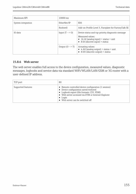
Liquiline CM442R/CM444R/CM448R Technical data
Endress+Hauser 155
15.8.6 Web server
The web server enables full access to the device configuration, measured values, diagnostic messages, logbooks and service data via standard WiFi/WLAN/LAN/GSM or 3G router with a user-defined IP address.
Maximum RPI 10000 ms
System integration EtherNet/IP EDS
Rockwell Add-on-Profile Level 3, Faceplate for FactoryTalk SE
IO data Input (T --> O) Device status and top-priority diagnostic message
Measured values:• 16 AI (analog input) + status + unit• 8 DI (discrete input) + status
Output (O --> T) Actuating values:• 4 A0 (analog output) + status + unit• 8 DO (discrete output) + status
TCP port 80
Supported features • Remote-controlled device configuration (1 session)• Device configuration saved/restored• Logbook export (file formats: CSV, FDM)• Web server accessed via DTM or Internet Explorer• Login• Web server can be switched off

Technical data Liquiline CM442R/CM444R/CM448R
156 Endress+Hauser
15.9 Power supply
15.9.1 Supply voltage
CM442RDepending on the version:100 to 230 V AC ± 15 %, 50/60 Hz24 V AC/DC +20 / -15 %, 50/60 Hz
CM444R and CM448RDepending on the version via external DIN rail power unit:100 to 230 V AC ± 15 %, 50/60 Hz24 V DC +20 / -15 %
15.9.2 Cable specification
Display cable
Length of display cable supplied (only for optional display):3 m (10 ft)Maximum permitted length of a display cable:5 m (16.5 ft)
15.9.3 Power consumption
CM442RDepending on supply voltage• 100 to 230 V AC and 24 V AC:
Max. 55 VA• 24 V DC:
Max. 22 W
CM444R and CM448RDepending on supply voltage• 100 to 230 V AC:
Max. 150 VA• 24 V DC:
Max. 59 W
15.9.4 Mains fuse
CM442R5x20 mm, 250 V, 4.0 A, slow-blow (T4.0A)
CM444R and CM448RFuse is not exchangeable
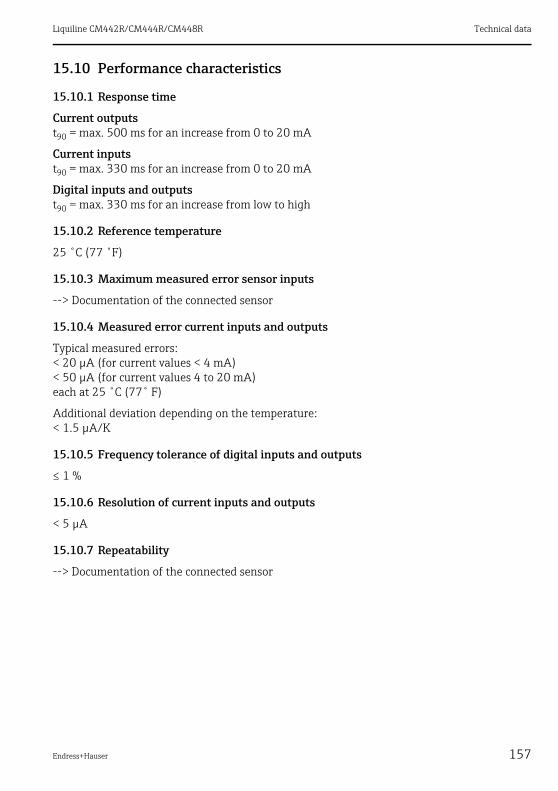
Liquiline CM442R/CM444R/CM448R Technical data
Endress+Hauser 157
15.10 Performance characteristics
15.10.1 Response time
Current outputst90 = max. 500 ms for an increase from 0 to 20 mA
Current inputst90 = max. 330 ms for an increase from 0 to 20 mA
Digital inputs and outputst90 = max. 330 ms for an increase from low to high
15.10.2 Reference temperature
25 ˚C (77 ˚F)
15.10.3 Maximum measured error sensor inputs
--> Documentation of the connected sensor
15.10.4 Measured error current inputs and outputs
Typical measured errors:< 20 μA (for current values < 4 mA)< 50 μA (for current values 4 to 20 mA)each at 25 ˚C (77˚ F)
Additional deviation depending on the temperature:< 1.5 μA/K
15.10.5 Frequency tolerance of digital inputs and outputs
≤ 1 %
15.10.6 Resolution of current inputs and outputs
< 5 μA
15.10.7 Repeatability
--> Documentation of the connected sensor

Technical data Liquiline CM442R/CM444R/CM448R
158 Endress+Hauser
15.11 Environment
15.11.1 Ambient temperature range
CM442R0 to 60 ˚C (32 to 140 ˚F)
CM444R• 0 to 55 ˚C (32 to 130 ˚F) in general, with the exception of the packages listed under the 2nd
bullet point• 0 to 50 ˚C (32 to 120 ˚F) for the following packages:
– CM444R-**M40A7FI*+...– CM444R-**M40A7FK*+...
CM448R• 0 to 55 ˚C (32 to 130 ˚F) in general, with the exception of the packages listed under the 2nd
bullet point• 0 to 50 ˚C (32 to 120 ˚F) for the following packages:
– CM448R-***6AA*+...– CM448R-***8A4*+...– CM448R-***8A5*+...– CM448R-**28A3*+...– CM448R-**38A3*+...– CM448R-**48A3*+...– CM448R-**58A3*+...– CM448R-**68A3*+...– CM448R-**26A5*+...– CM448R-**36A5*+...– CM448R-**46A5*+...– CM448R-**56A5*+...– CM448R-**66A5*+...– CM448R-**22A7*+...– CM448R-**32A7*+...– CM448R-**42A7*+...– CM448R-**52A7*+...– CM448R-**62A7*+...
External display (optional)–20 to 60 ˚C (0 to 140 ˚F)
15.11.2 Storage temperature
–25 to 85 ˚C (–13 to 185 ˚F)

Liquiline CM442R/CM444R/CM448R Technical data
Endress+Hauser 159
15.11.3 Humidity
DIN rail device
5 to 85%, not condensating
External display (in installed state)
10 to 95%, not condensating
15.11.4 Degree of protection
IP 66 at front, if installed correctly and with appropriate protective enclosure
15.11.5 Climate class
As per IEC 60654-1: B2
15.11.6 Vibration resistance
Environmental testsVibration test based on DIN EN 60068-2, October 2008Vibration test based on DIN EN 60654-3, August 1998
15.11.7 Electromagnetic compatibility
Interference emission and interference immunity as per EN 61326-1: 2006, class A for industry
15.11.8 Electrical safety
IEC 61010-1, Class I equipmentLow voltage: overvoltage category IIEnvironment < 2000 m (< 6562 ft) above MSL
15.11.9 Pollution degree
The product is suitable for pollution degree 2.
Wall mountingFrequency rangeAmplitude
10 to 150 Hz (sinusoidal)10 to 12.9 Hz:12.9 to 150 Hz:
0.75 mm0.5 g 1)
Test duration 10 frequency cycles/ spatial axis, in 3 spatial axes (1 oct./min)
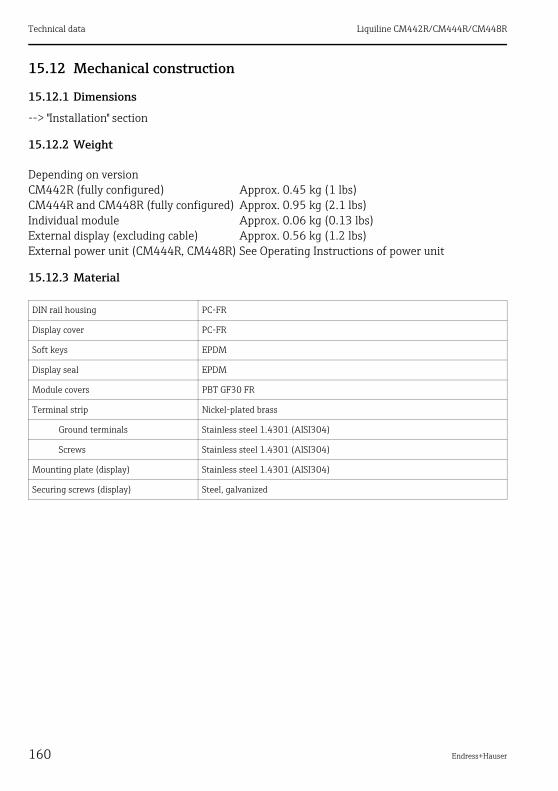
Technical data Liquiline CM442R/CM444R/CM448R
160 Endress+Hauser
15.12 Mechanical construction
15.12.1 Dimensions
--> "Installation" section
15.12.2 Weight
15.12.3 Material
Depending on versionCM442R (fully configured) Approx. 0.45 kg (1 lbs)CM444R and CM448R (fully configured) Approx. 0.95 kg (2.1 lbs)Individual module Approx. 0.06 kg (0.13 lbs)External display (excluding cable) Approx. 0.56 kg (1.2 lbs)External power unit (CM444R, CM448R) See Operating Instructions of power unit
DIN rail housing PC-FR
Display cover PC-FR
Soft keys EPDM
Display seal EPDM
Module covers PBT GF30 FR
Terminal strip Nickel-plated brass
Ground terminals Stainless steel 1.4301 (AISI304)
Screws Stainless steel 1.4301 (AISI304)
Mounting plate (display) Stainless steel 1.4301 (AISI304)
Securing screws (display) Steel, galvanized
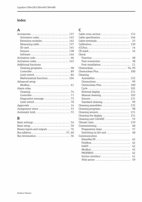
Endress+Hauser
Liquiline CM442R/CM444R/CM448R
Index
AAccessories . . . . . . . . . . . . . . . . . . . . . . . . . . . 137
Activation codes . . . . . . . . . . . . . . . . . . . . . 143Extension modules . . . . . . . . . . . . . . . . . . . 142Measuring cable . . . . . . . . . . . . . . . . . . . . . 137SD card . . . . . . . . . . . . . . . . . . . . . . . . . . . . 145Sensors . . . . . . . . . . . . . . . . . . . . . . . . . . . . 138Software . . . . . . . . . . . . . . . . . . . . . . . . . . . 144
Activation code. . . . . . . . . . . . . . . . . . . . . . . . . 66Activation codes . . . . . . . . . . . . . . . . . . . . . . . 143Additional functions
Cleaning programs . . . . . . . . . . . . . . . . . . . . 98Controller . . . . . . . . . . . . . . . . . . . . . . . . . . . 89Limit switch . . . . . . . . . . . . . . . . . . . . . . . . . 84Mathematical functions . . . . . . . . . . . . . . . 104
Advanced setupModbus. . . . . . . . . . . . . . . . . . . . . . . . . . . . . 61
Alarm relayCleaning . . . . . . . . . . . . . . . . . . . . . . . . . . . . 74Controller . . . . . . . . . . . . . . . . . . . . . . . . . . . 71Diagnostics message . . . . . . . . . . . . . . . . . . 73Limit switch . . . . . . . . . . . . . . . . . . . . . . . . . 70
Approvals . . . . . . . . . . . . . . . . . . . . . . . . . . . . . 14Assignment views . . . . . . . . . . . . . . . . . . . . . . 53Automatic hold. . . . . . . . . . . . . . . . . . . . . . . . . 55
BBasic settings . . . . . . . . . . . . . . . . . . . . . . . . . . 54Basic setup . . . . . . . . . . . . . . . . . . . . . . . . . . . . 50Binary inputs and outputs . . . . . . . . . . . . . . . . 76Bus address. . . . . . . . . . . . . . . . . . . . . . . . . 37, 60Bus termination . . . . . . . . . . . . . . . . . . . . . . . . 36
CCable cross-section . . . . . . . . . . . . . . . . . . . . 153Cable specification . . . . . . . . . . . . . . . . . . . . 146Cable terminals . . . . . . . . . . . . . . . . . . . . . . . . 25Calibration. . . . . . . . . . . . . . . . . . . . . . . . . . . 130cCSAus. . . . . . . . . . . . . . . . . . . . . . . . . . . . . . . 14CE mark . . . . . . . . . . . . . . . . . . . . . . . . . . . . . . 14Check
Function . . . . . . . . . . . . . . . . . . . . . . . . . . . 48Post-connection . . . . . . . . . . . . . . . . . . . . . 38Post-installation . . . . . . . . . . . . . . . . . . . . . 21
Chemoclean. . . . . . . . . . . . . . . . . . . . . . . . 34, 99Chemoclean Plus . . . . . . . . . . . . . . . . . . . . . . 100Cleaning
Assemblies . . . . . . . . . . . . . . . . . . . . . . . . 132Chemoclean. . . . . . . . . . . . . . . . . . . . . . . . . 99Chemoclean Plus . . . . . . . . . . . . . . . . . . . . 100Cycle . . . . . . . . . . . . . . . . . . . . . . . . . . . . . 102External display . . . . . . . . . . . . . . . . . . . . 131Manual cleaning . . . . . . . . . . . . . . . . . . . . 103Sensors . . . . . . . . . . . . . . . . . . . . . . . . . . . 131Standard cleaning . . . . . . . . . . . . . . . . . . . . 99
Cleaning assemblies . . . . . . . . . . . . . . . . . . . 132Cleaning programs . . . . . . . . . . . . . . . . . . . . . 98Cleaning sensors . . . . . . . . . . . . . . . . . . . . . . 131Cleaning the display . . . . . . . . . . . . . . . . . . . 131Cleaning unit CAS40D . . . . . . . . . . . . . . . . . . 33Climate class . . . . . . . . . . . . . . . . . . . . . . . . . 159Commissioning . . . . . . . . . . . . . . . . . . . . . . . . 48
Preparatory steps . . . . . . . . . . . . . . . . . . . . 37Switching on the unit . . . . . . . . . . . . . . . . . 48
CommunicationEtherNet/IP . . . . . . . . . . . . . . . . . . . . . . . . . 42Fieldbus . . . . . . . . . . . . . . . . . . . . . . . . . . . . 42HART . . . . . . . . . . . . . . . . . . . . . . . . . . . . . . 42Modbus . . . . . . . . . . . . . . . . . . . . . . . . . . . . 42PROFIBUS . . . . . . . . . . . . . . . . . . . . . . . . . . 42Service interface . . . . . . . . . . . . . . . . . . . . . 41Web server . . . . . . . . . . . . . . . . . . . . . . . . . 39

Liquiline CM442R/CM444R/CM448R
162
ConfigurationActions . . . . . . . . . . . . . . . . . . . . . . . . . . . . . 46Customized text . . . . . . . . . . . . . . . . . . . . . . 46Display only . . . . . . . . . . . . . . . . . . . . . . . . . 45Numerical values . . . . . . . . . . . . . . . . . . . . . 46Picklists . . . . . . . . . . . . . . . . . . . . . . . . . . . . . 45Tables . . . . . . . . . . . . . . . . . . . . . . . . . . . . . . 47
ConnectionCable terminals. . . . . . . . . . . . . . . . . . . . . . . 25Check . . . . . . . . . . . . . . . . . . . . . . . . . . . . . . 38Chemoclean . . . . . . . . . . . . . . . . . . . . . . . . . 34Cleaning unit CAS40D . . . . . . . . . . . . . . . . . 33Current input . . . . . . . . . . . . . . . . . . . . . . . . 32Current output . . . . . . . . . . . . . . . . . . . . . . . 32Digital input/output . . . . . . . . . . . . . . . . . . . 31Fieldbus. . . . . . . . . . . . . . . . . . . . . . . . . . . . . 35Relay . . . . . . . . . . . . . . . . . . . . . . . . . . . . . . . 33Sensors . . . . . . . . . . . . . . . . . . . . . . . . . 28–30Service interface . . . . . . . . . . . . . . . . . . . . . . 41Supply voltage. . . . . . . . . . . . . . . . . . . . 26–27Web server . . . . . . . . . . . . . . . . . . . . . . . . . . 39
Connection conditions . . . . . . . . . . . . . . . . . . . 22Controller . . . . . . . . . . . . . . . . . . . . . . . . . 71, 89Controller structure . . . . . . . . . . . . . . . . . . . . . 89Creating a connection
Service interface . . . . . . . . . . . . . . . . . . . . . . 41Web server . . . . . . . . . . . . . . . . . . . . . . . . . . 39
Current inputConnection . . . . . . . . . . . . . . . . . . . . . . . . . . 32Technical data. . . . . . . . . . . . . . . . . . . . . . . 147
Current inputs. . . . . . . . . . . . . . . . . . . . . . . . . . 67Current output
Connection . . . . . . . . . . . . . . . . . . . . . . . . . . 32Technical data. . . . . . . . . . . . . . . . . . . . . . . 151
DData management
Activation code . . . . . . . . . . . . . . . . . . . . . . . 66Exporting the setup . . . . . . . . . . . . . . . . . . . 65Firmware update . . . . . . . . . . . . . . . . . . . . . 64Loading the setup . . . . . . . . . . . . . . . . . . . . . 65Saving the setup . . . . . . . . . . . . . . . . . . . . . . 64
Data transmission rate . . . . . . . . . . . . . . . . . . 148Date and time . . . . . . . . . . . . . . . . . . . . . . . . . . 54DDs . . . . . . . . . . . . . . . . . . . . . . . . . . . . . . . . . 153Declaration of Conformity . . . . . . . . . . . . . . . . 14Degree of protection . . . . . . . . . . . . . . . . 37, 159Designated use . . . . . . . . . . . . . . . . . . . . . . . . . . 7
Device architecture . . . . . . . . . . . . . . . . . . 11–12Device behavior . . . . . . . . . . . . . . . . . . . . . . . 116Device description . . . . . . . . . . . . . . . . . . . . . . 10Device description files . . . . . . . . . . . . . . . . . 153Device information . . . . . . . . . . . . . . . . . . . . 127Device status . . . . . . . . . . . . . . . . . . . . . . . . . . 52Device test . . . . . . . . . . . . . . . . . . . . . . . . . . . 126Device type . . . . . . . . . . . . . . . . . . . . . . . . . . 153Device variables . . . . . . . . . . . . . . . . . . . . 74, 153
PROFIBUS . . . . . . . . . . . . . . . . . . . . . . . . . . 74Device-specific errors . . . . . . . . . . . . . . . . . . 114Diagnostic information
Fieldbus . . . . . . . . . . . . . . . . . . . . . . . . . . . 114Onsite display . . . . . . . . . . . . . . . . . . . . . . 114Web browser . . . . . . . . . . . . . . . . . . . . . . . 114
Diagnostic list . . . . . . . . . . . . . . . . . . . . . . . . 121Diagnostic message
Classification . . . . . . . . . . . . . . . . . . . . . . . 115Device behavior, adjusting . . . . . . . . . . . . 116Device-specific . . . . . . . . . . . . . . . . . . . . . . 118Pending message. . . . . . . . . . . . . . . . . . . . 121Sensor-specific . . . . . . . . . . . . . . . . . . . . . 121
DiagnosticsDevice test/reset . . . . . . . . . . . . . . . . . . . . 126Event logbook . . . . . . . . . . . . . . . . . . . . . . 121Sensor information . . . . . . . . . . . . . . . . . . 128Simulation . . . . . . . . . . . . . . . . . . . . . . . . . 125System information. . . . . . . . . . . . . . . . . . 127
Diagnostics settings. . . . . . . . . . . . . . . . . . . . . 59Digital input. . . . . . . . . . . . . . . . . . . . . . . . . . 147Digital input/output
Connection . . . . . . . . . . . . . . . . . . . . . . . . . 31Digital output. . . . . . . . . . . . . . . . . . . . . . . . . 150Dimensions . . . . . . . . . . . . . . . . . . . . . . . . . . 160Display . . . . . . . . . . . . . . . . . . . . . . . . . . . . 43, 51
Assignment views . . . . . . . . . . . . . . . . . . . . 53Device status . . . . . . . . . . . . . . . . . . . . . . . . 52Measuring mode . . . . . . . . . . . . . . . . . . . . . 51Soft keys . . . . . . . . . . . . . . . . . . . . . . . . . . . 51
Display cable . . . . . . . . . . . . . . . . . . . . . . 16, 156Display icons . . . . . . . . . . . . . . . . . . . . . . . . . . 52Display settings . . . . . . . . . . . . . . . . . . . . . . . . 48Documentation . . . . . . . . . . . . . . . . . . . . . . . . . 6

Liquiline CM442R/CM444R/CM448R
Endress+Hauser
EElectrical connection . . . . . . . . . . . . . 22, 25–35
Functional ground . . . . . . . . . . . . . . . . . . . . 29Mains fuse . . . . . . . . . . . . . . . . . . . . . . . . . 156Power consumption . . . . . . . . . . . . . . . . . . 156
Electrical safety . . . . . . . . . . . . . . . . . . . . . . . 159Electrical technician . . . . . . . . . . . . . . . . . . . . . 22Electromagnetic compatibility . . . . . . . . . . . . . . 8EMC . . . . . . . . . . . . . . . . . . . . . . . . . . . . . . . . 159Environment
Ambient temperature range . . . . . . . . . . . 158Climate class. . . . . . . . . . . . . . . . . . . . . . . . 159Degree of protection. . . . . . . . . . . . . . . . . . 159Electrical safety . . . . . . . . . . . . . . . . . . . . . 159EMC . . . . . . . . . . . . . . . . . . . . . . . . . . . . . . 159Pollution degree . . . . . . . . . . . . . . . . . . . . . 159Relative humidity . . . . . . . . . . . . . . . . . . . . 159Storage temperature . . . . . . . . . . . . . . . . . 158Vibration resistance . . . . . . . . . . . . . . . . . . 159
Error categories . . . . . . . . . . . . . . . . . . . . . . . 115Ethernet
Quick wiring guide . . . . . . . . . . . . . . . . . . . . 24EtherNet/IP . . . . . . . . . . . . . . . . . . . . . . . . 62, 75
General . . . . . . . . . . . . . . . . . . . . . . . . . . . . . 42Quick wiring guide . . . . . . . . . . . . . . . . . . . . 24
Event logbook . . . . . . . . . . . . . . . . . . . . . . . . . 121Extended setup
Data management . . . . . . . . . . . . . . . . . . . . 64Diagnostics settings . . . . . . . . . . . . . . . . . . . 59EtherNet/IP . . . . . . . . . . . . . . . . . . . . . . . . . 62HART bus address . . . . . . . . . . . . . . . . . . . . 60PROFIBUS . . . . . . . . . . . . . . . . . . . . . . . . . . . 60Webserver . . . . . . . . . . . . . . . . . . . . . . . . . . 63
Extension modules . . . . . . . . . . . . . . . . . . . . . 142External display . . . . . . . . . . . . . . . . . . . . . 17, 19
FFieldbus . . . . . . . . . . . . . . . . . . . . . . . . . . . . . 114
Module 485 . . . . . . . . . . . . . . . . . . . . . . . . . 35Setting the address via the hardware . . . . . 37Termination . . . . . . . . . . . . . . . . . . . . . . . . . 36
Fieldbuses . . . . . . . . . . . . . . . . . . . . . . . . . . . . . 42Firmware history . . . . . . . . . . . . . . . . . . . . . . 129Firmware update
Controller . . . . . . . . . . . . . . . . . . . . . . . . . . . 64Functional ground connection . . . . . . . . . . . . . 29
GGalvanic isolation . . . . . . . . . . . . . . . . . . . . . 148General settings
Automatic hold . . . . . . . . . . . . . . . . . . . . . . 55Basic settings . . . . . . . . . . . . . . . . . . . . . . . 54Date and time . . . . . . . . . . . . . . . . . . . . . . . 54Extended setup . . . . . . . . . . . . . . . . . . . . . . 59Logbooks . . . . . . . . . . . . . . . . . . . . . . . . . . . 56
HHART . . . . . . . . . . . . . . . . . . . . . . . . . . . . . . . . 74
General . . . . . . . . . . . . . . . . . . . . . . . . . . . . 42Quick wiring guide . . . . . . . . . . . . . . . . . . . 22
HART version . . . . . . . . . . . . . . . . . . . . . . . . 153
IIdentification
Nameplate. . . . . . . . . . . . . . . . . . . . . . . . . . 13Serial number . . . . . . . . . . . . . . . . . . . . . . . 14
Incoming acceptance. . . . . . . . . . . . . . . . . . . . 13Input
Cable specification . . . . . . . . . . . . . . . . . . 146Current input. . . . . . . . . . . . . . . . . . . . . . . 147Digital input . . . . . . . . . . . . . . . . . . . . . . . 147Input signal . . . . . . . . . . . . . . . . . . . . . . . . 146Input type . . . . . . . . . . . . . . . . . . . . . . . . . 146Measured variable . . . . . . . . . . . . . . . . . . 146Measuring range. . . . . . . . . . . . . . . . . . . . 146Numbering . . . . . . . . . . . . . . . . . . . . . . . . . 11
InputsBinary . . . . . . . . . . . . . . . . . . . . . . . . . . . . . 80
Installation . . . . . . . . . . . . . . . . . . . . . . . . . . . 15Check . . . . . . . . . . . . . . . . . . . . . . . . . . . . . . 21
IT security . . . . . . . . . . . . . . . . . . . . . . . . . . . . . . 9
KKeypad lock . . . . . . . . . . . . . . . . . . . . . . . . . . . 45
LLaplace representation . . . . . . . . . . . . . . . . . . 89LEDs . . . . . . . . . . . . . . . . . . . . . . . . . . . . . . . . 35Limit switch. . . . . . . . . . . . . . . . . . . . . . . . 70, 84Linearization . . . . . . . . . . . . . . . . . . . . . . . . . 149Load. . . . . . . . . . . . . . . . . . . . . . . . . . . . . . . . 149Locking operating keys . . . . . . . . . . . . . . . . . . 45Logbooks . . . . . . . . . . . . . . . . . . . . . 56, 121–124
Liquiline CM442R/CM444R/CM448R
164
MMains fuse . . . . . . . . . . . . . . . . . . . . . . . . . . . 156Manufacturer ID . . . . . . . . . . . . . . . . . . . . . . . 153Material . . . . . . . . . . . . . . . . . . . . . . . . . . . . . 160Mathematical functions
Degassed conductivity . . . . . . . . . . . . . . . . 106Difference . . . . . . . . . . . . . . . . . . . . . . . . . . 104Dual conductivity . . . . . . . . . . . . . . . . . . . . 107pH calculation . . . . . . . . . . . . . . . . . . . . . . . 108Redundancy . . . . . . . . . . . . . . . . . . . . . . . . 105rH value. . . . . . . . . . . . . . . . . . . . . . . . . . . . 106
Measured errorCurrent inputs. . . . . . . . . . . . . . . . . . . . . . . 157Current outputs . . . . . . . . . . . . . . . . . . . . . 157Sensor inputs . . . . . . . . . . . . . . . . . . . . . . . 157
Measured variable . . . . . . . . . . . . . . . . . . . . . 146Measuring cable . . . . . . . . . . . . . . . . . . . . . . . 137Measuring mode. . . . . . . . . . . . . . . . . . . . . . . . 51Measuring range . . . . . . . . . . . . . . . . . . . . . . 146Measuring range switch . . . . . . . . . . . . . . . . . 109Mechanical construction
Dimensions . . . . . . . . . . . . . . . . . . . . . . . . . 160Material . . . . . . . . . . . . . . . . . . . . . . . . . . . 160Weight . . . . . . . . . . . . . . . . . . . . . . . . . . . . 160
MemosensFunctional ground connection . . . . . . . . . . . 29
MenuBasic setup . . . . . . . . . . . . . . . . . . . . . . . . . . 50Display/Operation . . . . . . . . . . . . . . . . . . . . 48
Modbus . . . . . . . . . . . . . . . . . . . . . . . . . . . . . . . 61General . . . . . . . . . . . . . . . . . . . . . . . . . . . . . 42Quick wiring guide . . . . . . . . . . . . . . . . . . . . 24
Modbus RS485 . . . . . . . . . . . . . . . . . . . . . . . . . 75Modbus TCP . . . . . . . . . . . . . . . . . . . . . . . . . . . 75Mounting conditions
External display . . . . . . . . . . . . . . . . . . . . . . 17Wall mounting . . . . . . . . . . . . . . . . . . . . . . . 16
Mounting the measuring deviceDIN rail mounting. . . . . . . . . . . . . . . . . 15, 18External display . . . . . . . . . . . . . . . . . . . . . . 19Wall mounting . . . . . . . . . . . . . . . . . . . . . . . 19
NNameplate . . . . . . . . . . . . . . . . . . . . . . . . . . . . 13
OOccupational safety . . . . . . . . . . . . . . . . . . . . . . 8Onsite display . . . . . . . . . . . . . . . . . . . . . . . . 114Operation
Configuration . . . . . . . . . . . . . . . . . . . . . . . 45Display and operating elements . . . . . . . . . 43Operating concept . . . . . . . . . . . . . . . . . . . . 44Via service interface . . . . . . . . . . . . . . . . . . 41Via web server . . . . . . . . . . . . . . . . . . . . . . . 40
Operational safety . . . . . . . . . . . . . . . . . . . . . . . 8Output
Current output. . . . . . . . . . . . . . . . . . . . . . 151Digital output . . . . . . . . . . . . . . . . . . . . . . 150Linearization . . . . . . . . . . . . . . . . . . . . . . . 149Load . . . . . . . . . . . . . . . . . . . . . . . . . . . . . . 149Numbering . . . . . . . . . . . . . . . . . . . . . . . . . 11Output signal . . . . . . . . . . . . . . . . . . . . . . . 148Protocol-specific data . . . . . . . . . . . . . . . . 153Relay . . . . . . . . . . . . . . . . . . . . . . . . . . . . . 152Signal on alarm . . . . . . . . . . . . . . . . . . . . . 149
OutputsAlarm relay . . . . . . . . . . . . . . . . . . . . . . . . . 70binary. . . . . . . . . . . . . . . . . . . . . . . . . . . . . . 81Current outputs . . . . . . . . . . . . . . . . . . . . . . 68Relay (optional) . . . . . . . . . . . . . . . . . . . . . . 70
PPending diagnostic message . . . . . . . . . . . . . 121Performance characteristics
Measured error . . . . . . . . . . . . . . . . . . . . . 157Reference temperature . . . . . . . . . . . . . . . 157Repeatability . . . . . . . . . . . . . . . . . . . . . . . 157Resolution . . . . . . . . . . . . . . . . . . . . . . . . . 157Response time . . . . . . . . . . . . . . . . . . . . . . 157
Pollution degree . . . . . . . . . . . . . . . . . . . . . . 159Ports. . . . . . . . . . . . . . . . . . . . . . . . . . . . . . . . . 11Power consumption. . . . . . . . . . . . . . . . . . . . 156Power supply . . . . . . . . . . . . . . . . . . . . . . . . . 156Process errors . . . . . . . . . . . . . . . . . . . . . . . . 113Product identification . . . . . . . . . . . . . . . . . . . 13Product safety . . . . . . . . . . . . . . . . . . . . . . . . . . 9PROFIBUS . . . . . . . . . . . . . . . . . . . . . . . . . 60, 74
Device variables . . . . . . . . . . . . . . . . . . . . . . 74General . . . . . . . . . . . . . . . . . . . . . . . . . . . . 42PROFIBUS variables. . . . . . . . . . . . . . . . . . . 75Quick wiring guide . . . . . . . . . . . . . . . . . . . 23
Protocol-specific data . . . . . . . . . . . . . . . . . . 153

Liquiline CM442R/CM444R/CM448R
Endress+Hauser
RReference temperature. . . . . . . . . . . . . . . . . . 157Relative humidity . . . . . . . . . . . . . . . . . . . . . . 159Relay . . . . . . . . . . . . . . . . . . . . . . . . . . . . . . . . . 33
Cable cross-section. . . . . . . . . . . . . . . . . . . 153Cleaning . . . . . . . . . . . . . . . . . . . . . . . . . . . . 74Controller . . . . . . . . . . . . . . . . . . . . . . . . . . . 71Diagnostics message . . . . . . . . . . . . . . . . . . 73Limit switch . . . . . . . . . . . . . . . . . . . . . . . . . 70Switching capacity . . . . . . . . . . . . . . . . . . . 152
Relay types . . . . . . . . . . . . . . . . . . . . . . . . . . . 152Remote operation
Ethernet . . . . . . . . . . . . . . . . . . . . . . . . . . . . 24EtherNet/IP . . . . . . . . . . . . . . . . . . . . . . . . . 24HART . . . . . . . . . . . . . . . . . . . . . . . . . . . . . . 22Modbus. . . . . . . . . . . . . . . . . . . . . . . . . . . . . 24PROFIBUS . . . . . . . . . . . . . . . . . . . . . . . . . . . 23Web server . . . . . . . . . . . . . . . . . . . . . . . . . . 24
Repeatability. . . . . . . . . . . . . . . . . . . . . . . . . . 157Reset . . . . . . . . . . . . . . . . . . . . . . . . . . . . . . . . 126Resolution
Current inputs . . . . . . . . . . . . . . . . . . . . . . 157Current outputs . . . . . . . . . . . . . . . . . . . . . 157
Response time . . . . . . . . . . . . . . . . . . . . . . . . 157
SSafety instructions
Designated use . . . . . . . . . . . . . . . . . . . . . . . . 7Occupational safety . . . . . . . . . . . . . . . . . . . . 8Operational safety . . . . . . . . . . . . . . . . . . . . . 8Product safety. . . . . . . . . . . . . . . . . . . . . . . . . 9
Scope of delivery. . . . . . . . . . . . . . . . . . . . . . . . 14SD card . . . . . . . . . . . . . . . . . . . . . . . . . . . . . . 145Security
IT. . . . . . . . . . . . . . . . . . . . . . . . . . . . . . . . . . . 9Sensor information. . . . . . . . . . . . . . . . . . . . . 128
SensorsChlorine. . . . . . . . . . . . . . . . . . . . . . . . . . . 141Conductivity, conductive . . . . . . . . . . . . . . 140Conductivity, inductive . . . . . . . . . . . . . . . 140Connection . . . . . . . . . . . . . . . . . . . . . . 28–30Enamel pH electrodes . . . . . . . . . . . . . . . . 138Interface . . . . . . . . . . . . . . . . . . . . . . . . . . 142ISE . . . . . . . . . . . . . . . . . . . . . . . . . . . . . . . 141Nitrate . . . . . . . . . . . . . . . . . . . . . . . . . . . . 142ORP sensors . . . . . . . . . . . . . . . . . . . . . . . 139Oxygen . . . . . . . . . . . . . . . . . . . . . . . . . . . 141pH glass electrodes . . . . . . . . . . . . . . . . . . 138pH-ISFET . . . . . . . . . . . . . . . . . . . . . . . . . . 139SAC . . . . . . . . . . . . . . . . . . . . . . . . . . . . . . 142Turbidity . . . . . . . . . . . . . . . . . . . . . . . . . . 142Types . . . . . . . . . . . . . . . . . . . . . . . . . . . . . . 28
Serial number . . . . . . . . . . . . . . . . . . . . . . . . . 14Service interface
Connection . . . . . . . . . . . . . . . . . . . . . . . . . 41Creating a connection . . . . . . . . . . . . . . . . . 41
Setting the operating language . . . . . . . . . . . 48Setup
Export . . . . . . . . . . . . . . . . . . . . . . . . . . . . . 65Load. . . . . . . . . . . . . . . . . . . . . . . . . . . . . . . 65Save . . . . . . . . . . . . . . . . . . . . . . . . . . . . . . . 64
Signal encoding . . . . . . . . . . . . . . . . . . . . . . . 148Simulation . . . . . . . . . . . . . . . . . . . . . . . . . . . 125Slots . . . . . . . . . . . . . . . . . . . . . . . . . . . . . . . . . 11Soft keys . . . . . . . . . . . . . . . . . . . . . . . . . . . . . 51Spare parts . . . . . . . . . . . . . . . . . . . . . . . . . . 133State of the art . . . . . . . . . . . . . . . . . . . . . . . . . . 9Status display . . . . . . . . . . . . . . . . . . . . . . . . . 43Storage temperature . . . . . . . . . . . . . . . . . . . 158Supply voltage . . . . . . . . . . . . . . . . . . . . . . . . 156
CM442 . . . . . . . . . . . . . . . . . . . . . . . . . . . . 26CM444/CM448 . . . . . . . . . . . . . . . . . . . . . 27
Switching on the unit . . . . . . . . . . . . . . . . . . . 48Symbols . . . . . . . . . . . . . . . . . . . . . . . . . . . . . . . . 5System information . . . . . . . . . . . . . . . . . . . 127System integration . . . . . . . . . . . . . . . . . . . . . 39
Liquiline CM442R/CM444R/CM448R
166
TTechnical data. . . . . . . . . . . . . . . . . . . . . . . . . 146
Environment . . . . . . . . . . . . . . . . . . . . . . . . 158Input . . . . . . . . . . . . . . . . . . . . . . . . . . . . . . 146Mechanical construction . . . . . . . . . . . . . . 160Output . . . . . . . . . . . . . . . . . . . . . . . . . . . . . 148Performance characteristics . . . . . . . . . . . . 157
Terminal diagram . . . . . . . . . . . . . . . . . . . . . . . 12Troubleshooting . . . . . . . . . . . . . . . . . . 113–121
UUse . . . . . . . . . . . . . . . . . . . . . . . . . . . . . . . . . . . 7
VVibration resistance . . . . . . . . . . . . . . . . . . . . 159
WWarnings . . . . . . . . . . . . . . . . . . . . . . . . . . . . . . 5Web browser. . . . . . . . . . . . . . . . . . . . . . . . . . 114Web server . . . . . . . . . . . . . . . . . . . . . . . . . . . . 63
Connection . . . . . . . . . . . . . . . . . . . . . . . . . . 39Creating a connection. . . . . . . . . . . . . . . . . . 39Operation . . . . . . . . . . . . . . . . . . . . . . . . . . . 40Quick wiring guide . . . . . . . . . . . . . . . . . . . . 24
Weight . . . . . . . . . . . . . . . . . . . . . . . . . . . . . . 160

Liquiline CM442R/CM444R/CM448R
Endress+Hauser

www.addresses.endress.com