Embed Size (px)
Citation preview

Operating Instructions
BA 8704 EN 11.05
ARPEX® - All Steel Couplingsincl. design according to Directive 94/9/EC
ARW-4/6 ARF-6
ARS-6
ARH-8
ARP-6
ARC-6/8/10
A. Friedr. Flender AG ⋅ 46393 Bocholt ⋅ Tel. 02871/92-0 ⋅ Telefax 02871/92-2596 ⋅ www.flender.com

� � ��
BA 8704 EN 11.05
Contents
1. Technical Data 4
2. General information 52.1 Introduction 52.2 Copyright 5
3. Safety notes 63.1 Intended use 63.2 Fundamental duties 63.3 Warnings and symbols used in these Operating Instructions 7
4. Transport and storage 84.1 Scope of supply 84.2 Transport 84.3 Storage 84.3.1 Storage of coupling parts 84.3.2 Storage of plate packs 84.3.2.1 General 84.3.2.2 Storage area 8
5. Technical description 95.1 General description 95.2 Marking of the coupling parts according to Directive 94/9/EC 105.3 Operating conditions 10
6. Assembly 116.1 Information on machining finish bores, axial safeguarding, set screws, balancing 116.1.1 Finish bore 116.1.1.1 Keyway 126.1.2 Axial safeguarding 136.1.3 Setscrews 136.1.4 Balancing 136.2 General information on assembly 146.3 Mounting of coupling parts (shaft-hub connection with key) 156.4 Disassembly of shaft-hub connection with key 166.5 Shrink connections 176.5.1 Assembly 176.5.2 Disassembly 176.6 Clamping hub and sliding hub connection 186.6.1 Assembly 186.6.2 Disassembly 196.7 Splitted clamping hubs with half-shell 206.7.1 Assembly 206.7.2 Disassembly 206.8 Splitted spacers 216.8.1 Assembly of splitted spacers 216.8.2 Assembly of splitted spacers with electrical insulation 226.9 Bolting of C-, D- and F-flange 236.9.1 Assembly 236.10 Assembly of summation balanced couplings 246.11 Assembly of the drive train 246.11.1 Mounting of spacer resp. intermediate unit 246.12 Assembly of the plate packs 25

� � ��
BA 8704 EN 11.05
7. Putting into service 267.1 Before operating 26
8. Operation 268.1 General operating data 26
9. Failures, causes and remedies 279.1 General 279.2 Possible failures 279.3 Incorrect use 289.3.1 Possible faults when selecting the coupling or coupling size 289.3.2 Possible faults when installing the coupling 289.3.3 Possible faults in maintenance 29
10. Maintenance 3010.1 General 3010.2 Replacing plate packs 30
11. Stocking of spare parts, addresses of service centres 3111.1 Adresses of service centres 31
12. Declaration by the Manufacturer / Declaration of Conformity 3712.1 Declaration by the Manufacturer 3712.2 Declaration of Conformity 38

� � ��
BA 8704 EN 11.05
1. Technical Data
The technical data such as dimensions, weights, rating data, peak torques, operating period, operatingtemperature range etc. according to the ARPEX couplings mentioned in these operating instructionsare documented in the product catalogues listed in table 1.1. These catalogues are available on requestor can be seen and downloaded at any time in the World Wide Web at www.flender.com.
In case of differences between the coupling design and the corresponding product catalogue, thedelivery contains a dimension drawing which includes all necessary technical data.
Series ARS-6 ARP-6 ARH-8 ARC-8/10 ARW-4/6 ARF-6
Catalogue no. K431 K4313 K430 K431 K431 K431
Table 1.1: Assignment of product catalogues
These data and the contractual agreement for the coupling determine the limits of its intended use.
For use in hazardous areas according to Directive 94/9/EC restrictedtemperature ranges are valid. The classification of the temperature classes isspecified in section 5.3 ”Operating conditions”.
In order to ensure continuous, trouble-free operation, the coupling has to beselected with a service factor, adequate to the application. In case of changesin operating conditions (power rating, speed, changes on driver or drivenmachine) re-examination of the design is urgently necessary.
Caution!

� � ��
BA 8704 EN 11.05
2. General information
2.1 Introduction
These operating instructions are constituent part of the coupling delivery and should always be keptaccessible near the coupling.
All persons involved in the installation, operation, maintenance and repair ofthe coupling must have read and understood these Operating Instructions andmust comply with them at all times. We accept no responsibility for damage ordisruption caused by disregard of these Instructions.
The “couplings“ dealt with in these Operating Instructions, have been designed for stationaryapplications in general mechanical engineering. The coupling serves to transmit power and torquebetween two shafts or flanges connected by this coupling.
The coupling described in these Operating Instructions, corresponds to the state of technicaldevelopment at the time of going to press.
In the interest of further development, whilst maintaining the essential characteristics, we reserve theright to make changes on single modules and accessory parts, which are deemed to increase itscapacity and safety.
2.2 Copyright
The copyright to these Operating Instructions is held by FLENDER.
These Operating Instructions must not be wholly or partly reproduced for competitive purposes, usedin any unauthorised way or made available to third parties without our agreement.
Technical enquiries should be addressed to the following works
FLENDER AG Phone: 02871/92-0D - 46393 Bocholt Telefax: 02871/92-2596
or to one of our customer-service addresses. A list of our customer-service addresses is given inchapter 11, ”Stocking of spare parts, addresses of service centres”.

� � ��
BA 8704 EN 11.05
3. Safety notes
3.1 Intended use
� The coupling has been designed according to the state of technology and is supplied in a safe tooperate condition. Unauthorized modification, which interfere with the operational safety are notpermitted. This applies also to guarding devices, which have been put up against unintentionalcontact.
� The coupling is to be installed and operated only within the scope of conditions laid down in the supplycontract.The coupling is designed only for the application range stated in the product catalogues (seechapter 1. of these Operating Instructions ”Technical data” and table 1.1). Any other or furthermoreuse or deviating operating conditions be considered as ”non-intended use” and necessitate a newcontractual agreement.For damages which result from this only the user/operator of the machine/application assumesliability.
3.2 Fundamental duties
� The operator has to ensure that all personnel engaged in assembly, operation, care and maintenance,have read and understood these operating instructions and that they strictly observe all points to:
– avert danger to life and limb of users and third parties
– safeguard the operational safety of the coupling
and
– exclude downtime and environmental damage through wrong handling.
� The relevant regulations and instructions concerning health and safety at work, and environmentprotection have to be observed for transport, assembly and disassembly, operation and maintenance.
� The coupling is to be operated and maintained only by authorised and trained personnel.
� All work has to be carried out carefully and from the point of view of “safety”.
� Any work on the coupling has to be carried out whilst it is at rest. The driver is to be safeguardedagainst unintentional starting (e.g. by locking the key switch or removing fuses in the mains supply).A notice should be placed at the start-up location which says that work is being carried out on thecoupling.
� The coupling is to be protected by appropriate protecting guards against accidental touching. Theprotecting guards must not impair the function of the coupling.
For use in hazardous areas the protecting guards must be conform to type ofprotection IP2X at least.
� The driver is to be switched off at once, if, during operation, any changes can be noticed on thecoupling.
� When the coupling is incorporated in machines or equipment, the manufacturer of the machine orequipment is obliged to include all instructions, notes and descriptions of these operating instructionsin his operating instructions.
� All spare parts must be obtained from FLENDER.

� ��
BA 8704 EN 11.05
3.3 Warnings and symbols used in these Operating Instructions
This symbol indicates safety measures which must be observed to avoid personalinjury.
This symbol indicates safety measures which must be observed to avoid damage tothe coupling.
This symbol indicates to safety measures, which must be observed especially for usein hazardous areas according to Directive 94/9/EC to avoid personal injuries andproperty damage.
Note: This symbol indicates general operating instructions which are of particularimportance.
Caution!

� � ��
BA 8704 EN 11.05
4. Transport and storage
Note: The instructions of section 3, ”Safety notes” must be observed.
4.1 Scope of supply
The scope of supply is listed on the transport documents. Its completeness should be checked ondelivery. Possible transport damage and/or missing parts should be reported immediately in writing.After consultation with Messrs. FLENDER an expert should be called in.
A damaged coupling becomes an explosion hazard. Operation of the couplingwith damaged coupling components in hazardous areas in conformity withDirective 94/9/EC is inadmissible.
4.2 Transport
When handling FLENDER products, use only lifting and handling equipment ofsufficient load-bearing capacity!
The coupling must be transported using suitable transport equipment only.
Subject to transport route and size, the coupling is packed differently. If not specially agreed in thecontract, the packing corresponds to guidelines HPE.
Possible symbols on the packaging should be noted. They have the following meaning:
bild-transport
This way Fragile Keep Keep Centre of Use no Attachup dry cool gravity hand hook here
4.3 Storage
4.3.1 Storage of coupling parts
The coupling is supplied with a protective coating and can be stored for up to 6 months, indoors at adry location. In case longer storage is intended, a corresponding long-term conservation is necessary(refer to FLENDER).
4.3.2 Storage of plate packs
4.3.2.1 General
Properly stored plate packs remain unchanged in their characteristics. Storage under unfavourableconditions and improper handling will have a negative influence and a change of physical propertieswill result. These changes can come about through reaction to extreme temperatures or damp forexample.
4.3.2.2 Storage area
The storage area should be dry and dust-free. The plate packs are not to be stored together withcorrosive chemicals, acids, alcaline solutions etc.
Damp storage places (relative humidity above 65%) are unsuitable. Care shouldbe taken that no condensation develops.Caution!

� ��
BA 8704 EN 11.05
5. Technical description
5.1 General description
Hub HubPlate pack
SpacerPlate pack
Hexagonring plate pack
Octagonside bar plate pack
Hexagonside bar plate pack
ARPEX couplings are all steel couplings. The plate packs are placed between the flanges of thecoupling parts and alternately bolted with them.
Individual thin steel plates are assembled on bushings and are pressed tightly together by inserted,internally bevelled, retaining rings. The retaining rings are fastened by the expanded ends of thebushings, which fit snugly against it.
Due to this arrangement at ring-disc-design the plate pack forms a compact unit. Side-bar-plate-packsare composed of single side bar discs which are beaded together in disc-strands which form, annularlycompounded, the plate pack.
Due to this arrangement of plate packs, the ARPEX coupling is torsionally stiff and torque is transmittedwithout backlash. In axial and radial direction the coupling remains flexible and is able to compensateaxial, radial and angular misalignments of the connected machines.
Depending on the coupling series collar bolts and collar nuts or conical bolt-units connect the platepacks with spacer- and coupling part flanges.
The size identification of the coupling defines the outside diameter (da) of coupling flange in mm as wellas the design of the plate pack (”-6” = hexagon). This identification is complemented by a precedingcombination of letters, which specify the coupling components.
Example: ARS-6 NHN 255-6Coupling with 2 hubs (N) and 1 H spacer (H) size 255 with hexagon plate pack ofseries ARS-6
�� � ��
BA 8704 EN 11.05
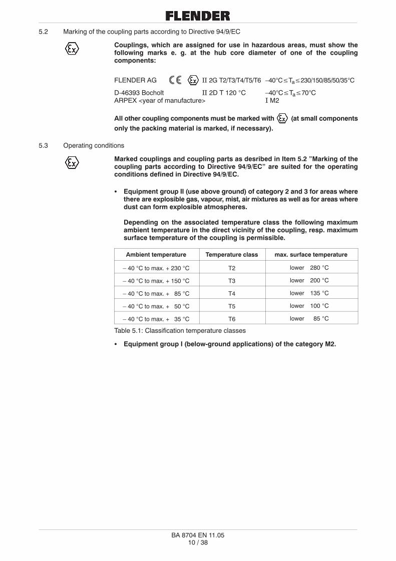
5.2 Marking of the coupling parts according to Directive 94/9/EC
Couplings, which are assigned for use in hazardous areas, must show thefollowing marks e. g. at the hub core diameter of one of the couplingcomponents:
FLENDER AG �� 2G T2/T3/T4/T5/T6 –40°C�Ta�230/150/85/50/35°C
D-46393 Bocholt �� 2D T 120 °C –40°C�Ta�70°CARPEX <year of manufacture> � M2
All other coupling components must be marked with (at small componentsonly the packing material is marked, if necessary).
5.3 Operating conditions
Marked couplings and coupling parts as desribed in Item 5.2 ”Marking of thecoupling parts according to Directive 94/9/EC” are suited for the operatingconditions defined in Directive 94/9/EC.
� Equipment group II (use above ground) of category 2 and 3 for areas wherethere are explosible gas, vapour, mist, air mixtures as well as for areas wheredust can form explosible atmospheres.
Depending on the associated temperature class the following maximumambient temperature in the direct vicinity of the coupling, resp. maximumsurface temperature of the coupling is permissible.
Ambient temperature Temperature class max. surface temperature
– 40 °C to max. + 230 °C T2 lower 280 °C
– 40 °C to max. + 150 °C T3 lower 200 °C
– 40 °C to max. + 85 °C T4 lower 135 °C
– 40 °C to max. + 50 °C T5 lower 100 °C
– 40 °C to max. + 35 °C T6 lower 85 °C
Table 5.1: Classification temperature classes
� Equipment group I (below-ground applications) of the category M2.
�� � ��
BA 8704 EN 11.05
6. Assembly
Note: The instructions of section 3, ”Safety notes” must be observed.
Couplings and coupling parts which will be operated in hazardous areas inconformity with Directive 94/9/EC, are delivered fundamentally only finishbored by the manufacturer.
For couplings which will not be operated in hazardous areas in conformity with Directive 94/9/ECFLENDER also delivers unbored or prebored coupling parts at customer’s request. The necessaryrefinishing must be carried out in strict compliance with the following specifications and with particularcare!
Responsibility for carrying out the refinishing is borne by the orderer.FLENDER can accept no guarantee claims arising from unsatisfactoryrefinishing!
The specified tightening torques in chapter 6 (table 6.2, 6.3 and 6.4) must beabsolutely kept. Deviating tightening torques may result in accelerated wear ofthe plates and damage of the coupling.
Non-observance of the instructions stated in this chapter may result inbreakage of the coupling. Flying metal fragments can cause serious personalinjuries!
A damaged coupling becomes an explosion hazard. Operation of the couplingwith damaged coupling components in hazardous areas in conformity withDirective 94/9/EC is inadmissible.
6.1 Information on machining finish bores, axial safeguarding, set screws, balancing
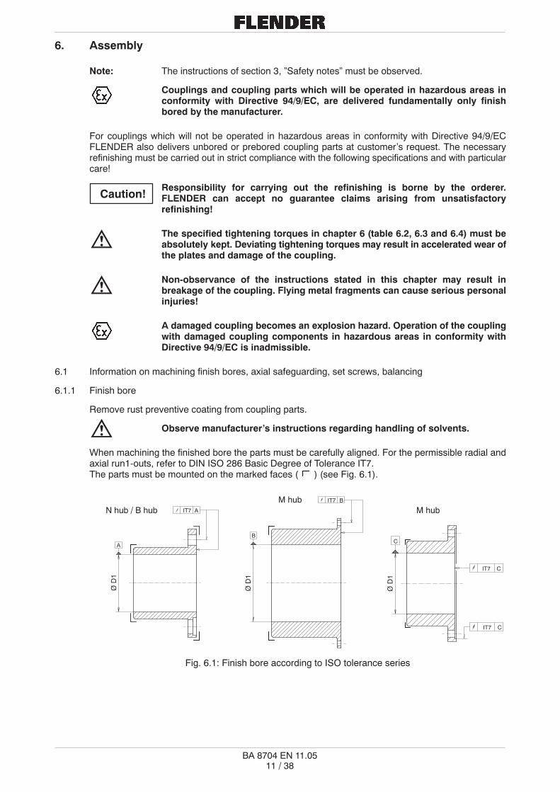
6.1.1 Finish bore
Remove rust preventive coating from coupling parts.
Observe manufacturer’s instructions regarding handling of solvents.
When machining the finished bore the parts must be carefully aligned. For the permissible radial andaxial run1-outs, refer to DIN ISO 286 Basic Degree of Tolerance IT7.The parts must be mounted on the marked faces ( ) (see Fig. 6.1).
N hub / B hubM hub
Ø D
1
Ø D
1
Ø D
1
M hubAIT7
A
BIT7
B
CIT7
C
CIT7
Fig. 6.1: Finish bore according to ISO tolerance series
Caution!
�� � ��
BA 8704 EN 11.05
The max. permissible bore diameters (see chapter 1 ”Technical data”) apply todrive type fastenings without taper action according to DIN 6885/1 and must notbe exceeded under any circumstances. The finished bores must be 100 %checked with suitable measuring equipment.
If instead of the planned drive type fastening other shaft- hub connections (e.g. splined hub profiles,tapered or stepped bores, stressed type fastenings with taper action) are to be used, consult FLENDER.
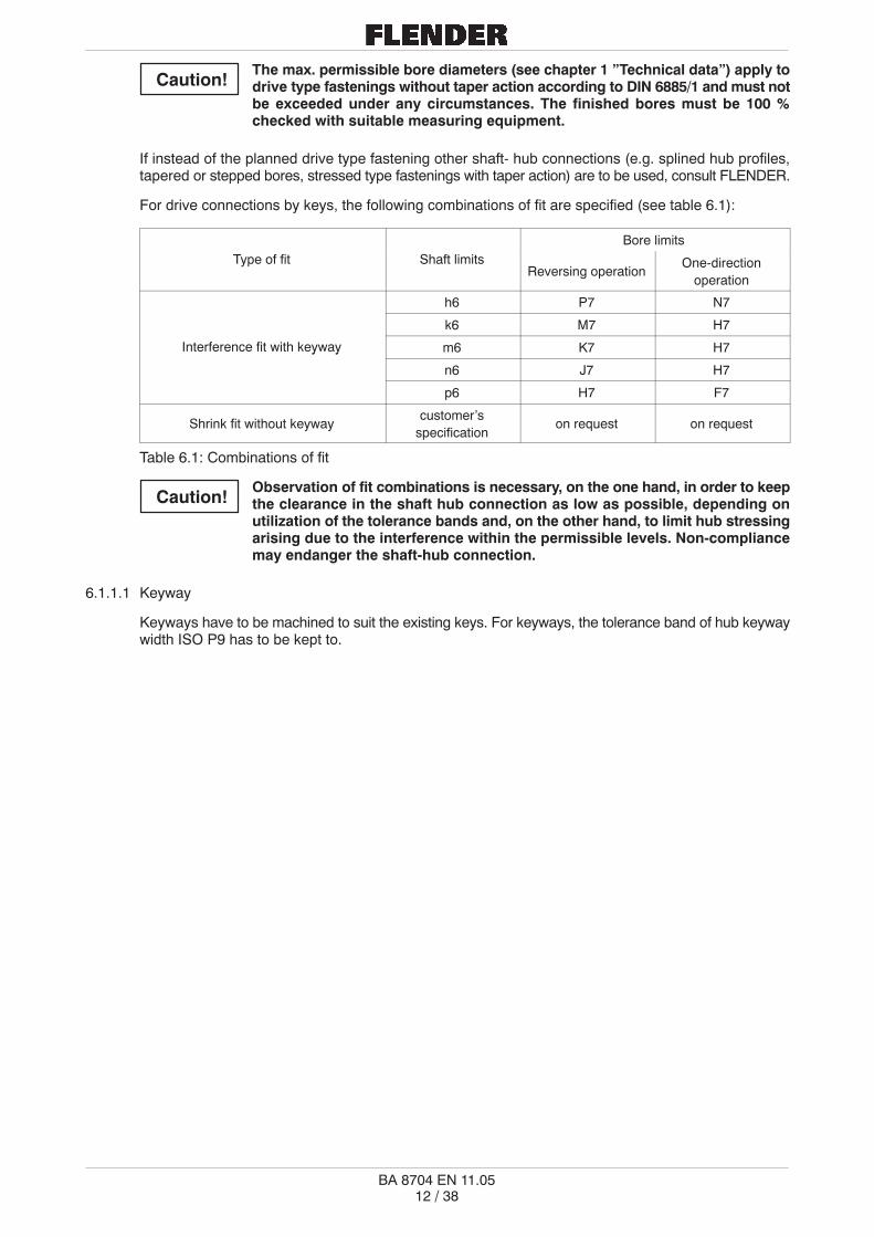
For drive connections by keys, the following combinations of fit are specified (see table 6.1):
Bore limits
Type of fit Shaft limitsReversing operation
One-directionoperation
h6 P7 N7
k6 M7 H7
Interference fit with keyway m6 K7 H7y y
n6 J7 H7
p6 H7 F7
Shrink fit without keywaycustomer’s
specificationon request on request
Table 6.1: Combinations of fit
Observation of fit combinations is necessary, on the one hand, in order to keepthe clearance in the shaft hub connection as low as possible, depending onutilization of the tolerance bands and, on the other hand, to limit hub stressingarising due to the interference within the permissible levels. Non-compliancemay endanger the shaft-hub connection.
6.1.1.1 Keyway
Keyways have to be machined to suit the existing keys. For keyways, the tolerance band of hub keywaywidth ISO P9 has to be kept to.
Caution!
Caution!

�� � ��
BA 8704 EN 11.05
6.1.2 Axial safeguarding
A setscrew or endplate must be used for axial safeguarding of coupling parts. If end plates are to beused, contact FLENDER with regard to the recessing of coupling parts.
6.1.3 Setscrews
To avoid damaging the shaft, the setscrew bore should be machined over thekeyway.In exceptional cases the setscrew has to be displaced by 180° according to thekeyway, if due to the bore and hub core diameter too little steel material remainsbetween keyway and hub core (e. g. series ARS-6 size 78-6).
The following guide lines should be observed:
The setscrews are to be located at the centre of the hubcore (see fig. 6.2). If this is not practical, please note that theclearance distance (e) to the set screw is to be at least M x 1.5.
Hexagon socket set screws with cup point according to DIN 916should be used.
e
M
Fig. 6.2: Bore for setscrew
The set screw length should fill the threaded hole but not project above the hub(Lmin. = M x 1.2).
6.1.4 Balancing
Rough drilled couplings resp. rough-drilled coupling parts are supplied in an unbalanced condition. Forthese components it is recommended that they are balanced, subject to their intended use, after finishboring (for this purpose, we refer to DIN 740, DIN ISO 1940 part 1).
Balancing is usually achieved by removing metal through drilling. In order to limit the material to beremoved to a minimum, a rather large equalizing radius should be chosen (see fig. 6.3).
Finish bored couplings or coupling parts are supplied in a balanced state according to customer’sspecification.
Fig. 6.3: Arrangement of balancing holes when balancing in one plane (after keyseating)
Caution!
�� � ��
BA 8704 EN 11.05
6.2 General information on assembly
Note: The instructions of section 3 ”Safety notes” must be observed.
Assembly is to be carried out with great care by skilled fitters.
Care should be taken, already at the planning stage, that adequate space is available for assembly andsubsequent maintenance work.
Adequate lifting gear should be on hand at the start of assembly.
Under no circumstances can any sort of welding work be allowed on thecoupling or coupling parts, as this will have a negative influence on themechanical properties of the coupling.
If lacquered couplings are used in hazardous zones, the requirements for theconductivity of the lacquer coating and the limitation of the thickness of theapplied lacquer coating in accordance with Guideline EN 13463 (Guidelines forthe avoidance of explosion hazards due to electrical charges) must beobserved. Where lacquer coatings have a thickness less than 200 �m, noelectrostatic charge is to be expected. Where lacquer coatings are thicker than200 �m, an electrostatic charge must be avoided, e.g. by cleaning the coupling.

L1 Distance ring
Fig. 6.4: Distance ring
�� � ��
BA 8704 EN 11.05
6.3 Mounting of coupling parts (shaft-hub connection with key)
Before starting assembly the bore holes and the bearing surfaces of the rings, bushes, nuts and reamedbolts resp. tapered sleeves and bushes (see section 6.12 ”Assembly of the plate packs” resp. separateassembly instructions) must be recovered from dirt and all kind of rust-preventative such as paint, Tectyletc. The same applies to shaft ends.
Observe manufacturer’s instructions regarding handling of solvents
The coupling parts have to be mounted using suitable equipment, so as toavoid damaging any shaft bearings through axial mounting force. Use suitablelifting gear.
Shaft ends should not protrude over hub inside faces. If necessary,place spacers or distance rings to bridge the gap between couplingand shaft shoulder (see fig. 6.4). Axial safeguarding by setscrewor endplate.
Tighten setscrews only with hex. keyaccording to DIN ISO 2936, without extensionpipe.
For hubs with key connection it is recommended to warm thecoupling hubs to max. 150 °C, this will facilitate mounting.
Take care not to get burned by hotcomponents!
A mounting device will ease fitting hubs with transition fits and heated hubs on the lightly oiled shaft end.
Bar is threaded into shaft end; size of thread depends on available shaft diameter. Put a plate ofappropriate size over the threaded bar. By tightening the nut the hub moves onto the shaft (see fig. 6.5).
Threaded bar
Disc
Nut
Fig. 6.5: Mounting of the hub with threaded bar
Caution!
Caution!

�� � ��
BA 8704 EN 11.05
6.4 Disassembly of shaft-hub connection with key
To pull a coupling hub from the shaft, the plate packs have to be disassembled first. Then remove theendplate if applicable resp. loosen setscrew. With the aid of a three-armed puller resp. by placing apulling device in the threaded holes (only in existence if demanded), remove the hub from the shaft(see fig. 6.6 and 6.7).
In case of a tight fit, warm the hub uniformly with a burner and carefully pull the hub with a pulling devicefrom the shaft.
Take care not to get burned by hot components!
Check disassembled components carefully before reuse or return them, if necessary, to FLENDER forrepairs.
Pulling holes
Fig. 6.6: Hub with pulling holes Fig. 6.7: Three-arm-puller(can not be used at all hubs)
� � ��
BA 8704 EN 11.05
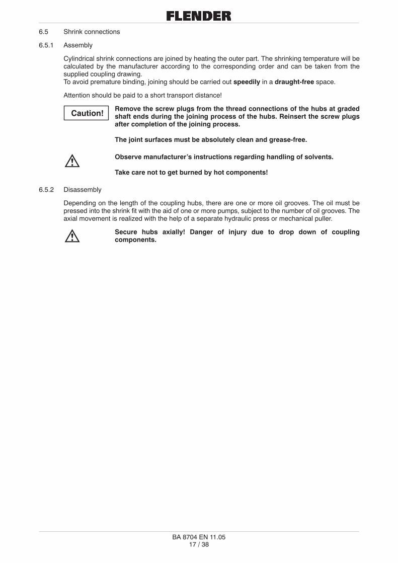
6.5 Shrink connections
6.5.1 Assembly
Cylindrical shrink connections are joined by heating the outer part. The shrinking temperature will becalculated by the manufacturer according to the corresponding order and can be taken from thesupplied coupling drawing.To avoid premature binding, joining should be carried out speedily in a draught-free space.
Attention should be paid to a short transport distance!
Remove the screw plugs from the thread connections of the hubs at gradedshaft ends during the joining process of the hubs. Reinsert the screw plugsafter completion of the joining process.
The joint surfaces must be absolutely clean and grease-free.
Observe manufacturer’s instructions regarding handling of solvents.
Take care not to get burned by hot components!
6.5.2 Disassembly
Depending on the length of the coupling hubs, there are one or more oil grooves. The oil must bepressed into the shrink fit with the aid of one or more pumps, subject to the number of oil grooves. Theaxial movement is realized with the help of a separate hydraulic press or mechanical puller.
Secure hubs axially! Danger of injury due to drop down of couplingcomponents.
Caution!

�� � ��
BA 8704 EN 11.05
6.6 Clamping hub and slipping hub connection
Power transmission of ARPEX clamping and slipping hubs is by frictional engagement. Clamping resp.slipping hubs are shipped in assembled condition, ready for mounting (see fig. 6.8 and 6.9).
Clamping screw
Taper surface“lubricated”
grease-free
Clamping ring Shaft
Clamping hub Forcing screw
Bronze bush
Forcing thread
ShaftClamping ringClamping hub
Taper surface“lubricated”
Clamping screwgrease-free
Fig. 6.8: Clamping hub type 124 Fig. 6.9: Slipping hub type 125(Example: ARS-6) (Example: ARS-6)
6.6.1 Assembly
Note the following procedure on assembly:
� Degrease shaft and hub bore.
Hub bore and shaft must be absolutely clean and grease-free.
Observe manufacturer’s instructions regarding handling of solvents.
� Loosen clamping screws slightly and pull clamping ring just a fraction off the hub, so that the clampingring is loose.
� Push hub on shaft.
� Tighten clamping screws evenly one after the other. Several turns must be made, until the clampingring fits snugly and evenly on the flange of the clamping resp. slipping hub. The clamp connection isready for use, when the tightening torque for clamping screws (quality 10.9), listed on page 22 intable 6.3 ”Tightening torques for connection and clamping screws”, has been reached and theclamping ring sits close against the hub flange.
Non-observance of these recommendations can impair the function of theclamping hub resp. slipping hub.Caution!

� � ��
BA 8704 EN 11.05
High pressure pump
Forcing screwISO 4017
G 1/4“
Fig. 6.10: Disassembly with High pressure pump
6.6.2 Disassembly
Loosen clamping screws evenly one after the other. Each screw should only be loosened by half arevolution per rotation. Free all clamping screws by 3 - 4 threads.
In case the clamping ring does not automatically come loose from the hub, additional forcing screws,depending on number of threaded holes (subject to size of coupling), have to be used on the ARPEXflange and evenly tightened, until the clamping ring comes loose. Before mounting the clamping ringagain, remove the forcing screws!
Subject to the size, clamping and slipping hubs of type 124 (see fig. 6.8) are already equipped withforcing screws in the clamping ring. Before mounting the clamping ring again, screw back the forcingscrews to their original position!
If the procedures described before are not successful at the bigger clamping hubs, oil has to be forcedinto the parting line between clamping ring and hub by high pressure pump; to remove thus the selfblocking of the clamping ring. For this purpose the high pressure hose of the pump is connected via theG 1/4” connecting thread on the outside diameter with the clamping ring (see fig. 6.10).
Before retightening the clamping ring remove the forcing screws and close the G 1/4” threaded hole withthe plug, supplied as part of the shipment.
If the clamping ring has been removed hydraulically, then the taper surfaces have to be cleaned toremove the hydraulic oil and greased again with Altemp Q NB 50 (Messrs. Klüber).
Observe manufacturer’s instructions regarding handling of solvents.
Dismounted clamping resp. slipping hub connections do not have to be further disassembled andregreased before retightening. But in case the cone faces are to be greased again, the above namedlubricant must be used.

�� � ��
BA 8704 EN 11.05
6.7 Splitted clamping hubs with half-shell
The half-shells are bolted loose with the hubs (see figure 6.11).
gap dimension
Numericmarking
Numericmarking
Fig. 6.11 Splitted clamping hub with half-shell
6.7.1 Assembly
Before assembling, remove the half-shells of the clamping hubs, clean the bores carefully, anddegrease it with an appropriate degreasing agent.
Observe manufacturer’s instructions regarding handling of solvents.
Do not interchange the half-shells!Take care of the equal numeric marking (numeric stamp codes) at the hub coreside of both halfs (see figure 6.11).
Set down the clamping hubs onto the shaft ends. Tighten the clamping screws of the half-shellconstantly but only hand tight at first.
Take care of regular fit of the half-shells. Check the regularity of the gapdimension and, if necessary, correct it.
After that, tighten the clamping screws alternately with a torque wrench in at least 3 turns (see table 6.2).
1. turn: Tightening of the clamping screws with 30% of the tightening torque (see table 6.2)
2. turn: Tightening of the clamping screws with 60% of the tightening torque (see table 6.2)
3. turn: Tightening of the clamping screws with 100% of the tightening torque (see table 6.2)
ScrewQ lit
Tightening torqueISO 4762 (DIN 912) Quality 30% 60% 100%
Thready
[Nm] [Nm] [Nm]
M6 4 8 12
M8 9 18 30
M1010 9
18 36 60
M1210.9
30 60 100
M14 48 96 160
M16 75 150 250
Table 6.2: Tightening torques for splitted clamping hubswith half-shell
6.7.2 Disassembly
The disassembly is executed as the assembly but in reverse order. Loosen the clamping screwsalternately in at least 2 - 3 turns.
Danger of injury due to drop down of coupling components!Secure all coupling components before loosen the clamping screws.
Caution!
Caution!

�� � ��
BA 8704 EN 11.05
6.8 Splitted spacers
Depending on the length, splitted spacers are supplied in pre-assembled, hand-tightened condition oras component parts.
6.8.1 Assembly of splitted spacers
� Before assembling, degrease the fitting bores and the bearing faces of the coupling parts carefully.
Fitting bores and bearing faces of the coupling parts must be absolutely cleanand grease-free.
Observe manufacturer’s instructions regarding handling of solvents.
� Internal and external recesses (see figure 6.12) resp. the fitting bores (see figure 6.13) as well as thebearing faces of the components of the splitted spacer have to be checked for possible damage andreworked if necessary.
� Before inserting the bolts, look for possible balancing markings (see figures 6.12 to 6.13). Atunmarked spacers the spacer halfs must be mounted in that way, that the fitting bores of the outerflanges lie opposite (see figures 6.12 to 6.13).
� Be very careful in fitting recess resp. fitting bolt connections.
� The connecting screws have to be tightened crosswise and evenly one after the other with thespecified tightening torque (see table 6.3 ”Tightening torques of connection and clamping screws”).
� Be careful that the recess connection is not tilted!
Non-observance of these instructions can impair the proper function of thecoupling.
ATEC fitting screw - 10.9
Markings at balanced spacerBalancing markings must be in line when assembling
Fitting bore
Fitting bore
All steel lock nut DIN 980 Form V ATEC collar nut
Hexagon head bolt ISO 4017 - 8.8
Fig. 6.12: U spacer with recess Fig. 6.13: U spacer with fitting screws(ARS-6) (ARC-8)
Caution!

Fitting bore
Electrical insulation
�� � ��
BA 8704 EN 11.05
Tightening torque TA Tightening torque TA Tightening torque TA
ThreadStandard screw+ standard nutto DIN and ISO
Standard screw+ locking nut to DIN 980
(see Fig. 6.12)
ATEC close–fitting screw+ ATEC flanged nut
Tensioning bolt
in quality 8.8 in qualityt 8.8 in quality 10.9
M 5 5 Nm 6 Nm 7 Nm
M 6 9 Nm 11 Nm 12 Nm
M 8 20 Nm 25 Nm 30 Nm
M 10 41 Nm 50 Nm 60 Nm
M 12 70 Nm 80 Nm 100 Nm
M 14 110 Nm 125 Nm 160 Nm
M 16 170 Nm 195 Nm 250 Nm
M 18 235 Nm 260 Nm 350 Nm
M 20 330 Nm 370 Nm 480 Nm
M 22 450 Nm 500 Nm 660 Nm
M 24 570 Nm 640 Nm 850 Nm
M 27 840 Nm 920 Nm 1200 Nm
M 30 1140 Nm 1200 Nm 1700 Nm
M 36 2000 Nm 2100 Nm 3100 Nm
Table 6.3: Tightening torques for connection and clamping screws
6.8.2 Assembly of splitted spacers with electrical insulation
Here, the same assembly instructions as described in section 6.8.1 take place, but for splitted spacerswith electrical insulation (see figure 6.14) the tightening torques according to table 6.4 ”Tighteningtorques for connection screws with electrical insulation” must be absolutely kept.
Thread Tightening torque TA
M 6 10 Nm
M 8 20 Nm
M 10 38 Nm
M 12 75 Nm
M 16 155 Nm
M 20 280 Nm
M 24 470 Nm
M 30 1000 Nm
M 36 1550 Nm
Fig. 6.14 Splitted spacer with Table 6.4: Tightening torques forelectrical insulation connection screws
with electrical insulation
The tightening torques specified in tables 6.3 and 6.4 are only valid foruntreated screws, which are used in ”as-delivered”-condition (only lightlyoiled).
For coated or specially treated screws different tightening torques are valid,which are specified additionally or to be asked for at the manufacturer.
Caution!
�� � ��
BA 8704 EN 11.05
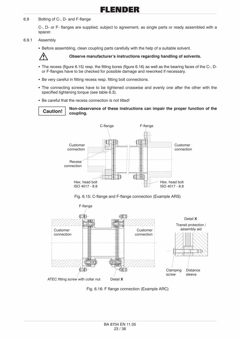
6.9 Bolting of C-, D- and F-flange
C-, D- or F- flanges are supplied, subject to agreement, as single parts or ready assembled with aspacer.
6.9.1 Assembly
� Before assembling, clean coupling parts carefully with the help of a suitable solvent.
Observe manufacturer’s instructions regarding handling of solvents.
� The recess (figure 6.15) resp. the fitting bores (figure 6.16) as well as the bearing faces of the C-, D-or F-flanges have to be checked for possible damage and reworked if necessary.
� Be very careful in fitting recess resp. fitting bolt connections.
� The connecting screws have to be tightened crosswise and evenly one after the other with thespecified tightening torque (see table 6.3).
� Be careful that the recess connection is not tilted!
Non-observance of these instructions can impair the proper function of thecoupling.
Hex. head boltISO 4017 - 8.8
C-flange F-flange
Customerconnection
Customerconnection
Recessconnection
Hex. head boltISO 4017 - 8.8
Fig. 6.15: C-flange and F-flange connection (Example ARS)
F-flange
Customerconnection
ATEC fitting screw with collar nut Detail X
Customerconnection
Detail X
Transit protection /assembly aid
Clampingscrew
Distancesleeve
Fig. 6.16: F flange connection (Example ARC)
Caution!

�� � ��
BA 8704 EN 11.05
6.10 Assembly of summation balanced couplings
Couplings which are summation balanced, have a 4-digit number stamped on each component flangeOD (see figure 6.17 ”AAAA”). Take care on assembly, that only coupling parts are bolted together whichhave the same numbers on their flange OD. The components have to be arranged so that numbers arein one line, to be readable from one direction (see fig. 6.17). Only this arrangement guarantees therequirements!
readable from here
Hub 1 Spacer Hub 2
Fig. 6.17: Marking of summation balanced couplings
6.11 Assembly of the drive train
Move the shafts of the machines to be connected together to exactly obtain the required shaft distanceand align the machines (see figure 6.18).
Shaft distancedimension Sx
Fig. 6.18: Alignment of the drive train
6.11.1 Mounting of spacer resp. intermediate unit
Insert the spacer resp. the intermediate unit between the flanges using appropriate lifting devices.
Attention, danger of bruising! Put on safety-gloves.
For intermediate units with pre-assembled plate packs it is not allowed to disassemble the plate packs.The plate packs are provided with transit protections (can also be used as assembly aids; seedetail X - figure 6.16).
After inserting the intermediate unit it is very essential to remove the transit protections, beforetightening the flange boltings with the specified tightening torques.
Operation with installed transit protections is inadmissible. Remove absolutelyall transit protections!
�� � ��
BA 8704 EN 11.05
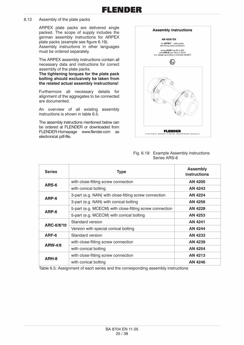
6.12 Assembly of the plate packs
ARPEX plate packs are delivered singlepacked. The scope of supply includes thegerman assembly instructions for ARPEXplate packs (example see figure 6.19).Assembly instructions in other languagesmust be ordered separately.
The ARPEX assembly instructions contain allnecessary data and instructions for correctassembly of the plate packs.The tightening torques for the plate packbolting should exclusively be taken fromthe related actual assembly instructions!
Furthermore all necessary details foralignment of the aggregates to be connectedare documented.
An overview of all existing assemblyinstructions is shown in table 6.5.
The assembly instructions mentioned below canbe ordered at FLENDER or downloaded fromFLENDER-Homepage www.flender.com aselectronical pdf-file.
Fig. 6.19: Example Assembly instructionsSeries ARS-6
Series TypeAssembly
instructions
ARS 6with close-fitting screw connection AN 4200
ARS-6with conical bolting AN 4243
ARP 63-part (e.g. NAN) with close-fitting screw connection AN 4224
ARP-63-part (e.g. NAN) with conical bolting AN 4256
ARP 65-part (e.g. MCECM) with close-fitting screw connection AN 4228
ARP-65-part (e.g. MCECM) with conical bolting AN 4253
ARC 6/8/10Standard version AN 4241
ARC-6/8/10Version with special conical bolting AN 4244
ARF-6 Standard version AN 4233
ARW 4/6with close-fitting screw connection AN 4239
ARW-4/6with conical bolting AN 4254
ARH 8with close-fitting screw connection AN 4213
ARH-8with conical bolting AN 4246
Table 6.5: Assignment of each series and the corresponding assembly instructions

�� � ��
BA 8704 EN 11.05
7. Putting into service
Note: The instructions of section 3, ”Safety notes” must be observed.
7.1 Before operating
Before putting into service check all bolt connections and retighten them if necessary. Alignment andgap dimension S1 should also be checked and corrected if necessary (see corresponding tables in theassembly instructions of the different series).
For coupling types with pre-assembled plate packs it is absolutely required to check if the transitprotection (see detail X - figure 6.16) is completely removed.
Then mount the coupling guard, protection against unintentional contact.
For use in hazardous areas the protecting guards must be conform to type ofprotection IP2X at least.
Failure to observe these instructions may result in breakage of the coupling.Flying metal fragments can cause serious personal injuries!
A damaged coupling becomes an explosion hazard. Operation of the couplingwith damaged coupling components in hazardous areas in conformity withDirective 94/9/EC is inadmissible.
8. Operation
Note: The instructions of section 3 ”Safety notes” must be observed.
8.1 General operating data
During operation, pay attention to
� changing running noises
� suddenly occurring vibrations.
In case any irregularities are noticed during operation, the drive must bestopped at once. Determine the cause of trouble with the aid of thetrouble-shooting check list (see chapter 9).
The check list features possible sources, their causes and proposals toeliminate them.
In case, the cause cannot be found resp. if there is no possibility to remedy thetrouble with own resources, we recommend calling for a service engineer fromone of our service depots (see chapter 11).
Caution!
� � ��
BA 8704 EN 11.05
9. Failures, causes and remedies
Note: The instructions of section 3, ”Safety notes” must be observed.
9.1 General
The following listed failures can only be clues in the search for any cause of faults.
In complex drive situations, all other components have to be included in the search.
During all operating phases, the coupling should run with low noise and without vibration. Differentoperating behaviour should be seen as a fault, which has to be remedied promptly.
FLENDER will not be bound by the terms of the guarantee or otherwise beresponsible in cases of improper use of the coupling, modifications carried outwithout FLENDER s agreement, or use of spare parts not supplied byFLENDER.
When remedying faults and malfunctions, the gear unit must always be takenout of service. Secure the drive unit to prevent it from being started upunintentionally. Attach a warning notice to the start switch.Otherwise we refer to the particular health and safety requirements for theinstallation.
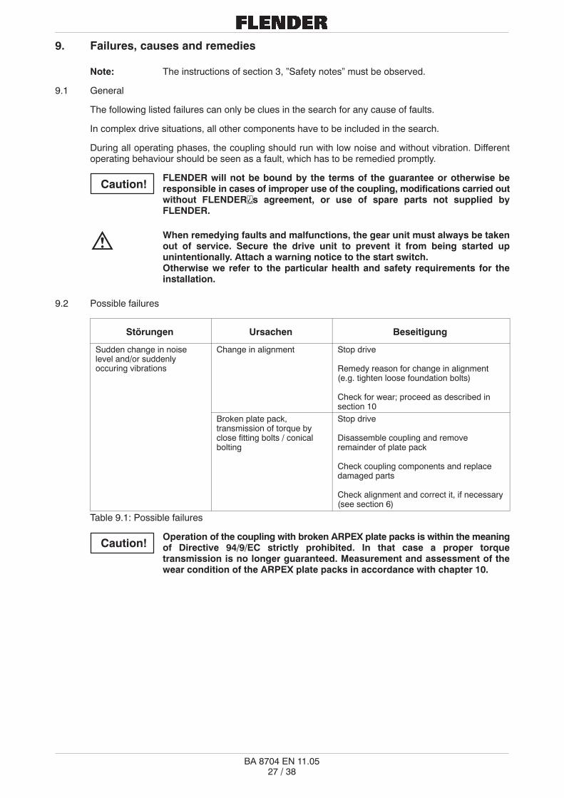
9.2 Possible failures
Störungen Ursachen Beseitigung
Sudden change in noiselevel and/or suddenlyoccuring vibrations
Change in alignment Stop drive
Remedy reason for change in alignment(e.g. tighten loose foundation bolts)
Check for wear; proceed as described insection 10
Broken plate pack,transmission of torque byclose fitting bolts / conicalbolting
Stop drive
Disassemble coupling and removeremainder of plate pack
Check coupling components and replacedamaged parts
Check alignment and correct it, if necessary(see section 6)
Table 9.1: Possible failures
Operation of the coupling with broken ARPEX plate packs is within the meaningof Directive 94/9/EC strictly prohibited. In that case a proper torquetransmission is no longer guaranteed. Measurement and assessment of thewear condition of the ARPEX plate packs in accordance with chapter 10.
Caution!
Caution!

�� � ��
BA 8704 EN 11.05
9.3 Incorrect use
Experience has shown that the following faults can result in incorrect use of the ARPEX coupling. Inaddition to observing the other instructions in these Operating Instructions, care must therefore betaken to avoid these faults.Directive 94/9/EC requires the manufacturer and user to exercise especial care.
Failure to observe these instructions may result in breakage of the coupling.Flying metal fragments can cause serious personal injuries!
Through incorrect use the coupling may become an explosion hazard.
Incorrect use of the ARPEX coupling may result in damage to the coupling.
Coupling damage may result in stoppage of the drive and the entire system.
9.3.1 Possible faults when selecting the coupling or coupling size
� Important information for describing the drive and the environment will not be communicated toothers.
� System torque too high.
� System speed too high.
� Application factor not correctly selected.
� Chemically aggressive environment not taken into consideration.
� The ambient temperature is not permissible.
� Finished bore with impermissible diameter resp. impermissible fit classification (see chapter 6).
� The transmission capacity of the shaft-hub connection is not appropriate to the operating conditions.
9.3.2 Possible faults when installing the coupling
� Components with transport or other damage are being fitted.
� When mounting coupling parts in a heated condition, this parts are being excessively heated.
� The shaft diameter is outside the specified tolerance range.
� Coupling components have been interchanged.
� Prescribed tightening torques resp. rotation angles are not being adhered to.
� Alignment or shaft misalignment values do not match the specifications of these operating orassembly instructions respectively.
� The coupled machines are not correctly fastened to the foundation, so a shifting of the machines e.g.through loosening of the foundation screw connection is causing excessive displacement of thecoupling parts.
� ARPEX plate packs are not installed correctly (see assembly instructions of each series).
� The coupling guard used is not suitable for operation within the meaning of the explosion protectionrequirements or according to Directive 94/9/EC.
� Operating conditions are being changed without authorisation.
Caution!
Caution!
� � ��
BA 8704 EN 11.05
9.3.3 Possible faults in maintenance
� Maintenance intervals are not being adhered to.
� Original ARPEX plate packs are not being used.
� Damaged ARPEX plate packs are being used.
� Use of ARPEX plate packs, which are not conform with the technical specification according to theapplication.
� Leakage in the vicinity of the coupling is not being identified and as a result chemically aggressivemedia are damaging the coupling.

�� � ��
BA 8704 EN 11.05
10. Maintenance
Note: The instructions of section 3, ”Safety notes” must be observed.
Any work on the coupling has to be carried out whilst it is at rest.The driver is to be safeguarded against unintentional starting (e.g. by lockingthe key switch or removing fuses in the mains supply). A notice should beplaced at the start-up location which says that work is being carried out on thecoupling.
10.1 General
ARPEX couplings should be visually checked corresponding to the maintenance schedules of the plant,but at least once a year. Special attention is to be paid to the condition of the plate packs. Shouldindividual plates or whole strands be broken, then the particular plate pack has to be replaced. In thesecases, check also the coupling flanges for damage.
Any further maintenance work is not necessary.
If the above specified maintenance instructions are not adhered to, a correctoperation within the meaning of the explosion prevention requirements andDirective 94/9/EC can no longer be guaranteed on the coupling.
Use in hazardous zones is then not permitted.
10.2 Replacing plate packs
Original ARPEX plate packs should only be used as replacement, to guarantee proper torquetransmission and trouble-free function.
Note: As a rule, replacing plate packs is possible without the necessity to shift coupled drivemembers. Exceptions are combinations with so-called B-hubs (hubs which areinserted into the spacer the other way round for space-reasons) and special designs.
For reassembly, carefully note instructions of section 6, “Assembly” and section 7, “Putting into service”.
�� � ��
BA 8704 EN 11.05
11. Stocking of spare parts, addresses of service centres
Storage of important spare and wearing parts at the site is an essential requirement for operationalavailability of the coupling.
When ordering spare parts, the following data has to be given:
Number of pieces, name of parts, size (if available, state also dwg. no. and position of spare parton the spare parts list)
If coupling parts are required with finish bore and balanced, specify the following:
Finish bore, fit, keyway and balancing quality
Examples of order: 1 piece ARPEX hub, series ARS-6, size 255with bore 70 H7 and keyway according to DIN 6885-1,single part dynamically balanced - after keyseating - G 2.5,speed 1000 min-1
1 piece ARPEX plate pack, series ARS-6, size 255 complete
We can only guarantee original spare parts supplied by us.
We expressly draw client’s attention to the fact that spare parts andaccessories not supplied by us, have not been checked and released by us.Their assembly and/or use can possibly alter design characteristics negativelyand thereby impair the active and/or passive safety. FLENDER excludes anyliability and guarantees for any damage which results from the use ofnon-original spare parts and accessories.
Please note that for individual components special manufacturing and supply specifications frequentlyexist and that we always offer spare parts according to the state of technology and latest legalrequirements.
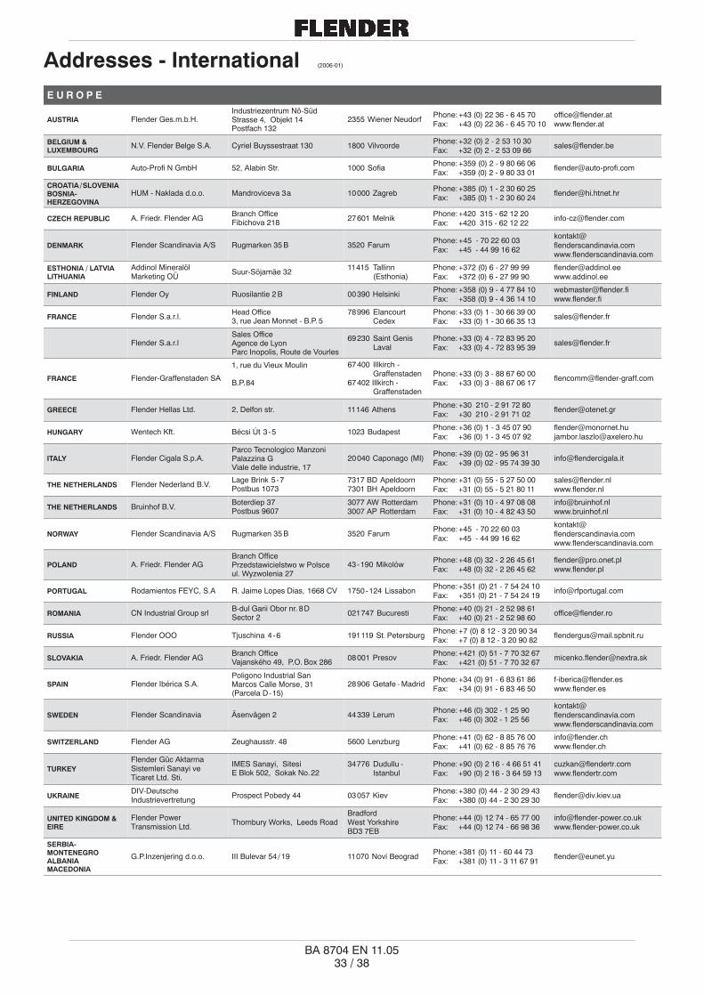
11.1 Adresses of service centres
When requesting spare parts or service fitter, contact FLENDER first.
Caution!

�� � ��
BA 8704 EN 11.05
Adressen - Deutschland (2006-01)
A. FRIEDR. FLENDER AGAlfred-Flender-Straße 7746395 Bocholt
Postfach 136446393 Bocholt
Tel.: (0 28 71) 92 - 0Fax: (0 28 71) 92 - 25 96
A. FRIEDR. FLENDER AGKundenservice Center Nord
Alfred-Flender-Straße 7746395 Bocholt
Postfach 136446393 Bocholt
Tel.: (0 28 71) 92 - 0Fax: (0 28 71) 92 - 14 35
A. FRIEDR. FLENDER AGKundenservice Center Süd
Bahnhofstraße 40 - 4472072 Tübingen
Postfach 170972007 Tübingen
Tel.: (0 70 71) 7 07 - 0Fax: (0 70 71) 7 07 - 3 40
A. FRIEDR. FLENDER AGKundenservice Center Süd(Außenstelle München)
Liebigstraße 14 85757 KarlsfeldTel.: (0 81 31) 90 03 - 0Fax: (0 81 31) 90 03 - 33
A. FRIEDR. FLENDER AGKundenservice CenterOst / Osteuropa
Schlossallee 8 13156 BerlinTel.: (0 30) 91 42 50 58Fax: (0 30) 47 48 79 30
A. FRIEDR. FLENDER AGWerk Friedrichsfeld
Am Industriepark 2 46562 VoerdeTel.: (0 28 71) 92 - 0Fax: (0 28 71) 92 - 25 96
A. FRIEDR. FLENDER AGGetriebewerk Penig
Thierbacher Straße 2409322 Penig
Postfach 44 / 4509320 Penig
Tel.: (03 73 81) 60Fax: (03 73 81) 8 02 86
A. FRIEDR. FLENDER AGKupplungswerk Mussum
Industriepark BocholtSchlavenhorst 100
46395 BocholtTel.: (0 28 71) 92 - 28 68Fax: (0 28 71) 92 - 25 79
A. FRIEDR. FLENDER AGFLENDER GUSS
Obere Hauptstraße228 - 230
09228 Chemnitz /Wittgensdorf
Tel.: (0 37 22) 64 - 0Fax: (0 37 22) 94 - 1 38
WINERGY AGAm Industriepark 246562 Voerde
Postfach 20116046553 Voerde
Tel.: (0 28 71) 9 24Fax: (0 28 71) 92 - 24 87
FLENDER TÜBINGEN GMBHBahnhofstraße 40 - 4472072 Tübingen
Postfach 170972007 Tübingen
Tel.: (0 70 71) 7 07 - 0Fax: (0 70 71) 7 07 - 4 00
LOHER GMBHHans-Loher-Straße 3294099 Ruhstorf
Postfach 116494095 Ruhstorf
Tel.: (0 85 31) 3 90Fax: (0 85 31) 3 94 37
A. FRIEDR. FLENDER AGFLENDER SERVICEINTERNATIONAL
Am Industriepark 246562 Voerde
Postfach 20116046553 Voerde
Tel.: (0 28 71) 92 - 22 10Fax: (0 28 71) 92 - 13 47
Werk HerneSüdstraße 11144625 Herne
Postfach 10172044607 Herne
Tel.: (0 23 23) 9 40 - 0Fax: (0 23 23) 9 40 - 3 33 [email protected]
www.flender-service.com
24h Service Hotline +49 (0) 17 22 81 01 00
www.flender service.com
Vertriebsbüro PenigThierbacher Straße 2409322 Penig
Postfach 44 / 4509320 Penig
Tel.: (03 73 81) 61 - 5 20Fax: (03 73 81) 61 - 4 88
�� � ��
BA 8704 EN 11.05
Addresses - International (2006-01)
E U R O P E
AUSTRIA Flender Ges.m.b.H.Industriezentrum Nö-SüdStrasse 4, Objekt 14Postfach 132
2355 Wiener NeudorfPhone: +43 (0) 22 36 - 6 45 70Fax: +43 (0) 22 36 - 6 45 70 10
BELGIUM &LUXEMBOURG
N.V. Flender Belge S.A. Cyriel Buyssestraat 130 1800 VilvoordePhone: +32 (0) 2 - 2 53 10 30Fax: +32 (0) 2 - 2 53 09 66
BULGARIA Auto-Profi N GmbH 52, Alabin Str. 1000 SofiaPhone: +359 (0) 2 - 9 80 66 06Fax: +359 (0) 2 - 9 80 33 01
CROATIA / SLOVENIABOSNIA-HERZEGOVINA
HUM - Naklada d.o.o. Mandroviceva 3 a 10 000 ZagrebPhone: +385 (0) 1 - 2 30 60 25Fax: +385 (0) 1 - 2 30 60 24
CZECH REPUBLIC A. Friedr. Flender AGBranch OfficeFibichova 218 27 601 Melnik
Phone: +420 315 - 62 12 20Fax: +420 315 - 62 12 22
DENMARK Flender Scandinavia A/S Rugmarken 35 B 3520 FarumPhone: +45 - 70 22 60 03Fax: +45 - 44 99 16 62
ESTHONIA / LATVIALITHUANIA
Addinol MineralölMarketing OÜ
Suur-Söjamäe 3211 415 Tallinn
(Esthonia)Phone: +372 (0) 6 - 27 99 99Fax: +372 (0) 6 - 27 99 90
FINLAND Flender Oy Ruosilantie 2 B 00 390 HelsinkiPhone: +358 (0) 9 - 4 77 84 10Fax: +358 (0) 9 - 4 36 14 10
FRANCE Flender S.a.r.l.Head Office3, rue Jean Monnet - B.P. 5
78 996 ElancourtCedex
Phone: +33 (0) 1 - 30 66 39 00Fax: +33 (0) 1 - 30 66 35 13
Flender S.a.r.lSales OfficeAgence de LyonParc Inopolis, Route de Vourles
69 230 Saint GenisLaval
Phone: +33 (0) 4 - 72 83 95 20Fax: +33 (0) 4 - 72 83 95 39
FRANCE Flender-Graffenstaden SA
1, rue du Vieux Moulin
B.P. 84
67 400 Illkirch -Graffenstaden
67 402 Illkirch -Graffenstaden
Phone: +33 (0) 3 - 88 67 60 00Fax: +33 (0) 3 - 88 67 06 17
GREECE Flender Hellas Ltd. 2, Delfon str. 11 146 AthensPhone: +30 210 - 2 91 72 80Fax: +30 210 - 2 91 71 02
HUNGARY Wentech Kft. Bécsi Út 3 - 5 1023 BudapestPhone: +36 (0) 1 - 3 45 07 90Fax: +36 (0) 1 - 3 45 07 92
[email protected]@axelero.hu
ITALY Flender Cigala S.p.A.Parco Tecnologico ManzoniPalazzina GViale delle industrie, 17
20 040 Caponago (MI)Phone: +39 (0) 02 - 95 96 31Fax: +39 (0) 02 - 95 74 39 30
THE NETHERLANDS Flender Nederland B.V.Lage Brink 5 - 7Postbus 1073
7317 BD Apeldoorn7301 BH Apeldoorn
Phone: +31 (0) 55 - 5 27 50 00Fax: +31 (0) 55 - 5 21 80 11
THE NETHERLANDS Bruinhof B.V.Boterdiep 37Postbus 9607
3077 AW Rotterdam3007 AP Rotterdam
Phone: +31 (0) 10 - 4 97 08 08Fax: +31 (0) 10 - 4 82 43 50
NORWAY Flender Scandinavia A/S Rugmarken 35 B 3520 FarumPhone: +45 - 70 22 60 03Fax: +45 - 44 99 16 62
POLAND A. Friedr. Flender AGBranch OfficePrzedstawicielstwo w Polsceul. Wyzwolenia 27
43 - 190 MikolówPhone: +48 (0) 32 - 2 26 45 61Fax: +48 (0) 32 - 2 26 45 62
PORTUGAL Rodamientos FEYC, S.A R. Jaime Lopes Dias, 1668 CV 1750 - 124 LissabonPhone: +351 (0) 21 - 7 54 24 10Fax: +351 (0) 21 - 7 54 24 19
ROMANIA CN Industrial Group srlB-dul Garii Obor nr. 8 DSector 2 021 747 Bucuresti
Phone: +40 (0) 21 - 2 52 98 61Fax: +40 (0) 21 - 2 52 98 60
RUSSIA Flender OOO Tjuschina 4 - 6 191 119 St. PetersburgPhone: +7 (0) 8 12 - 3 20 90 34Fax: +7 (0) 8 12 - 3 20 90 82
SLOVAKIA A. Friedr. Flender AGBranch OfficeVajanského 49, P.O. Box 286 08 001 Presov
Phone: +421 (0) 51 - 7 70 32 67Fax: +421 (0) 51 - 7 70 32 67
SPAIN Flender Ibérica S.A.Poligono Industrial SanMarcos Calle Morse, 31(Parcela D - 15)
28 906 Getafe - MadridPhone: +34 (0) 91 - 6 83 61 86Fax: +34 (0) 91 - 6 83 46 50
SWEDEN Flender Scandinavia Äsenvägen 2 44 339 LerumPhone: +46 (0) 302 - 1 25 90Fax: +46 (0) 302 - 1 25 56
SWITZERLAND Flender AG Zeughausstr. 48 5600 LenzburgPhone: +41 (0) 62 - 8 85 76 00Fax: +41 (0) 62 - 8 85 76 76
TURKEYFlender Güc AktarmaSistemleri Sanayi veTicaret Ltd. Sti.
IMES Sanayi, SitesiE Blok 502, Sokak No. 22
34 776 Dudullu -Istanbul
Phone: +90 (0) 2 16 - 4 66 51 41Fax: +90 (0) 2 16 - 3 64 59 13
UKRAINEDIV-DeutscheIndustrievertretung
Prospect Pobedy 44 03 057 KievPhone: +380 (0) 44 - 2 30 29 43Fax: +380 (0) 44 - 2 30 29 30
UNITED KINGDOM &EIRE
Flender PowerTransmission Ltd.
Thornbury Works, Leeds RoadBradfordWest YorkshireBD3 7EB
Phone: +44 (0) 12 74 - 65 77 00Fax: +44 (0) 12 74 - 66 98 36
SERBIA-MONTENEGROALBANIAMACEDONIA
G.P.Inzenjering d.o.o. III Bulevar 54 / 19 11 070 Novi BeogradPhone: +381 (0) 11 - 60 44 73Fax: +381 (0) 11 - 3 11 67 91

�� � ��
BA 8704 EN 11.05
A F R I C A
NORTH AFRICANCOUNTRIES
Flender S.a.r.l. 3, rue Jean Monnet - B.P. 578 996 Elancourt
CedexPhone: +33 (0) 1 - 30 66 39 00Fax: +33 (0) 1 - 30 66 35 13
EGYPT Sons of Farid Hassanen 81 Matbaa Ahlia Street Boulac 11 221, CairoPhone: +20 (0) 2 - 5 75 15 44Fax: +20 (0) 2 - 5 75 17 02
SOUTH AFRICAFlender PowerTransmission (Pty.) Ltd.
Head OfficeCnr. Furnace St & Quality Rd.P.O. Box 131
Isando - JohannesburgIsando 1600
Phone: +27 (0) 11 - 5 71 20 00Fax: +27 (0) 11 - 3 92 24 34
Flender PowerTransmission (Pty.) Ltd.
Sales OfficesUnit 3 Marconi Park, 9 MarconiCrescent, Montague Gardens,P.O. Box 37 291
Cape TownChempet 7442
Phone: +27 (0) 21 - 5 51 50 03Fax: +27 (0) 21 - 5 52 38 24
Flender PowerTransmission (Pty.) Ltd.
Unit 3 Goshawk ParkFalcon Industrial EstateP.O. Box 1608
New Germany - DurbanNew Germany 3620
Phone: +27 (0) 31 - 7 05 38 92Fax: +27 (0) 31 - 7 05 38 72
Flender PowerTransmission (Pty.) Ltd.
9 Industrial Crescent, Ext. 25P.O. Box 17 609
WitbankWitbank 1035
Phone: +27 (0) 13 - 6 92 34 38Fax: +27 (0) 13 - 6 92 34 52
Flender PowerTransmission (Pty.) Ltd.
Unit 14 King Fisher Park, AltonCnr. Ceramic Curve & AluminaAllee, P.O. Box 101 995
Richards BayMeerensee 3901
Phone: +27 (0) 35 - 7 51 15 63Fax: +27 (0) 35 - 7 51 15 64
A M E R I C A
ARGENTINA Chilicote S.A. Avda. Julio A. Roca 546C 1067 ABNBuenos Aires
Phone: +54 (0) 11 - 43 31 66 10Fax: +54 (0) 11 - 43 31 42 78
BRASIL Flender Brasil Ltda.Head OfficeRua Quatorze, 60Cidade Industrial
32 210 - 660Contagem - MG
Phone: +55 (0) 31 - 33 69 20 00Fax: +55 (0) 31 - 33 31 18 93
Flender Brasil Ltda.Sales OfficesRua James Watt, 152conjunto 142 - Brooklin Novo
04 576 - 050São Paulo - SP
Phone: +55 (0) 11 - 55 05 99 33Fax: +55 (0) 11 - 55 05 30 10
Flender Brasil Ltda.Rua Campos Sales, 1095sala 14 - centro
14 015 - 110Ribeirão Preto - SP
Phone: +55 (0) 16 - 6 35 15 90Fax: +55 (0) 16 - 6 35 11 05
Flender Brasil Ltda.Rua da Mitra - quadra 30 - lote 16Edifício Cristal - sala 207Bairro Renascença
65 075 - 770São Luis - MA
Phone: +55 (0) 98 - 32 25 84 92Fax: +55 (0) 98 - 32 25 84 93
Flender Brasil Ltda.Rua Padre Anchieta, 1691conjunto 1110 - Bairro Bigorrilho
80 730 - 000Curitiba - PR
Phone: +55 (0) 41 - 3 36 28 49Fax: +55 (0) 41 - 3 36 28 49
Flender Brasil Ltda.Rua José Alexandre Buaiz,160 sala 1017 - Enseada doSuá
29 050 - 545Vitória - ES
Phone: +55 (0) 27 - 32 24 37 35Fax: +55 (0) 27 - 32 24 37 36
CANADAFlender PowerTransmission Inc.
215 Shields Court, Units 4 - 6MarkhamOntario L3R 8V2
Phone: +1 (0) 9 05 - 3 05 10 21Fax: +1 (0) 9 05 - 3 05 10 23
CHILE / ARGENTINABOLIVIA / ECUADORPARAGUAYURUGUAY
Flender Cono Sur Ltda. Avda. Galvarino Gallardo 1534 Providencia, SantiagoPhone: +56 (0) 2 - 2 35 32 49Fax: +56 (0) 2 - 2 64 20 25
COLOMBIAA.G.P. RepresentacionesLtda.
Flender Liaison Office ColombiaAv Boyaca No. 23 A50 Bodega UA 7 - 1
BogotáPhone: +57 (0) 1 - 5 70 63 53Fax: +57 (0) 1 - 5 70 73 35
MEXICOFlender de MexicoS.A. de C.V.
Head Office17, Pte, 713 Centro 72 000 Puebla
Phone: +52 (0) 2 22 - 2 37 19 00Fax: +52 (0) 2 22 - 2 37 11 33
Flender de MexicoS.A. de C.V.
Sales OfficesLago Nargis No. 38Col. Granada
11 520 Mexico, D.F.Phone: +52 (0) 55 - 52 54 30 37Fax: +52 (0) 55 - 55 31 69 39
Flender de MexicoS.A. de C.V.
Ave. San Pedro No. 231 - 5Col. Miravalle 64 660 Monterrey, N.L.
Phone: +52 (0) 81 - 83 63 82 82Fax: +52 (0) 81 - 83 63 82 83
PERU Flender Cono Sur Ltda. Avda. Galvarino Gallardo 1534 Providencia, SantiagoPhone: +56 (0) 2 - 2 35 32 49Fax: +56 (0) 2 - 2 64 20 25
USA Flender Corporation950 Tollgate RoadP.O. Box 1449 Elgin, IL. 60 123
Phone: +1 (0) 8 47 - 9 31 19 90Fax: +1 (0) 8 47 - 9 31 07 11
Flender CorporationService Centers West4234 Foster Ave. Bakersfield, CA. 93 308
Phone: +1 (0) 6 61 - 3 25 44 78Fax: +1 (0) 6 61 - 3 25 44 70
VENEZUELA F. H. Transmisiones S.A.Calle Johan Schafer o SegundaCalle, Municipio Sucre Petare, Caracas
Phone: +58 (0) 2 12 - 21 52 61Fax: +58 (0) 2 12 - 21 18 38

�� � ��
BA 8704 EN 11.05
A S I A
BANGLADESHSRI LANKA
Flender LimitedNo. 2 St. George’s Gate Road5th Floor, Hastings Kolkata - 700 022
Phone: +91 (0) 33 - 2 23 05 45Fax: +91 (0) 33 - 2 23 18 57
PEOPLE’S REPUBLICOF CHINA
Flender Power Trans-mission (Tianjin) Co., Ltd.
Head OfficeShuanghu-Shuangchen Rd.West, Beichen EconomicDevelopment Area (BEDA)
Tianjin 300 400Phone: +86 (0) 22 - 26 97 20 63Fax: +86 (0) 22 - 26 97 20 61
Flender Power Trans-mission (Tianjin) Co., Ltd.
Sales OfficesC - 414, Lufthansa Center50 Liangmaqiao Rd.Chaoyang District
Beijing 100 016Phone: +86 (0) 10 - 64 62 21 51Fax: +86 (0) 10 - 64 62 21 43
Flender Power Trans-mission (Tianjin) Co., Ltd.
1101 - 1102 Harbour Ring Plaza18 Xizang Zhong Rd. Shanghai 200 001
Phone: +86 (0) 21 - 53 85 31 48Fax: +86 (0) 21 - 53 85 31 46
Flender Power Trans-mission (Tianjin) Co., Ltd.
Rm. 1503, Jianyin Building709 Jianshedadao, Hankou Wuhan 430 015
Phone: +86 (0) 27 - 85 48 67 15Fax: +86 (0) 27 - 85 48 68 36
Flender Power Trans-mission (Tianjin) Co., Ltd.
Rm. 2802, GuangzhouInternational Electronics Tower403 Huanshi Rd. East
Guangzhou 510 095Phone: +86 (0) 20 - 87 32 60 42Fax: +86 (0) 20 - 87 32 60 45
Flender Power Trans-mission (Tianjin) Co., Ltd.
G - 6 / F Guoxin Mansion77 Xiyu Street Chengdu 610 015
Phone: +86 (0) 28 - 86 19 83 72Fax: +86 (0) 28 - 86 19 88 10
Flender Power Trans-mission (Tianjin) Co., Ltd.
Rm. 3 - 705, Tower DCity Plaza Shenyang206 Nanjing Street (N)Heping District
Shenyang 110 001Phone: +86 (0) 24 - 23 34 20 48Fax: +86 (0) 24 - 23 34 20 46
Flender Power Trans-mission (Tianjin) Co., Ltd.
Rm. 302, Shanzi Zhong DaInternational Mansion30 Southern Rd.
Xi’an 710 002Phone: +86 (0) 29 - 87 20 32 68Fax: +86 (0) 29 - 87 20 32 04
Flender Power Trans-mission (Tianjin) Co., Ltd.
Rm. 23E, Xinhua Plaza, No. 6Renmin East Rd. Kunming 650 051
Phone: +86 (0) 871 - 3 12 43 68Fax: +86 (0) 871 - 3 12 45 66
Flender Power Trans-mission (Tianjin) Co., Ltd.
Rm. 1007, Building A, GoldenCenter, Jincheng InternationalPlaza, No. 68 Jingsan Rd.
Zhengzhou 450 008Phone: +86 (0) 371 - 5 38 80 85Fax: +86 (0) 371 - 5 38 80 89
Flender Power Trans-mission (Tianjin) Co., Ltd.
Rm. 908 (east), No. 188Guangzhou Rd. Nanjing 210 024
Phone: +86 (0) 25 - 83 24 25 50Fax: +86 (0) 25 - 83 24 48 20
Flender Power Trans-mission (Tianjin) Co., Ltd.
Rm. 1408, Pearl RiverInternational Building No. 99Xinkai Rd. Xigang District
Dalian 116 011Phone: +86 (0) 411 - 83 77 93 55Fax: +86 (0) 411 - 83 77 92 19
Flender Power Trans-mission (Tianjin) Co., Ltd.
Rm. 1401, Tianlin BuildingHunan Gold Source HotelNo. 279, Second BlockFurong Rd.
Changsha 410 007Phone: +86 (0) 731 - 5 16 73 09Fax: +86 (0) 731 - 5 16 47 46
INDIA Flender LimitedHead OfficeNo. 2 St. George’s Gate Road5th Floor
HastingsKolkata - 700 022
Phone: +91 (0) 33 - 22 23 05 45Fax: +91 (0) 33 - 22 23 18 57
Flender LimitedIndustrial Growth CentreRakhajungle
NimpuraKharagpur - 721 302
Phone: +91 (0) 3222 - 23 33 07Fax: +91 (0) 3222 - 23 33 64
Flender LimitedEastern Regional Sales OfficeNo. 2 St. George’s Gate Road5th Floor
HastingsKolkata - 700 022
Phone: +91 (0) 33 - 22 23 05 45Fax: +91 (0) 33 - 22 23 08 30
Flender LimitedWestern Regional Sales OfficePlot No. 23, Sector 19 - C
VashiNavi Mumbai - 400 705
Phone: +91 (0) 22 - 27 65 72 27Fax: +91 (0) 22 - 27 65 72 28
Flender LimitedSouthern Regional Sales Office41 Nelson Manickam Road
AminjikaraiChennai - 600 029
Phone: +91 (0) 44 - 23 74 39 21Fax: +91 (0) 44 - 23 74 39 19
Flender LimitedNorthern Regional Sales Office302 Bhikaji Cama Bhawan11 Bhikaji Cama Palace
New Delhi - 110 066Phone: +91 (0) 11 - 51 85 96 56Fax: +91 (0) 11 - 51 85 96 59
INDONESIA Flender Singapore Pte. Ltd.Representative Office6 - 01 Wisma PresisiJl. Taman Aries Blok A1 No. 1
Jakarta Barat 11 620Phone: +62 (0) 21 - 58 90 20 15Fax: +62 (0) 21 - 58 90 20 19
IRAN Cimaghand Co. Ltd.P.O. Box 15 745 - 493No. 13, 16th East StreetBeyhaghi Ave., Argentina Sq.
Tehran 15 156Phone: +98 (0) 21 - 8 73 02 14Fax: +98 (0) 21 - 8 73 39 70
ISRAEL Greenshpon Boaz 3 34487 HaifaPhone: +972 (0) 52 - 4 76 14 26Fax: +972 (0) 4 - 8 14 60 37
JAPAN Flender Japan Co., Ltd.WBG Marive East 21 FNakase 2 - 6Mihama-ku, Chiba-shi
Chiba 261 - 7121Phone: +81 (0) 43 - 2 13 39 30Fax: +81 (0) 43 - 2 13 39 55
KAZAKHSTAN KazGate GmbH Abay ave 143 480 009 AlmatyPhone: +7 (0) - 32 72 - 43 39 54Fax: +7 (0) - 32 72 - 77 90 82
KOREA Flender Ltd.7th Fl. Dorim Bldg.1823 Bangbae - DongSeocho - Ku
Seoul 137 - 060Phone: +82 (0) 2 - 34 78 63 37Fax: +82 (0) 2 - 34 78 63 45
KUWAIT South Gulf CompanyAl-Showaikh Ind. AreaP.O. Box 26229 Safat 13 123
Phone: +965 (0) - 4 82 97 15Fax: +965 (0) - 4 82 97 20
LEBANON Gabriel Acar & Fils s.a.r.l.Dahr-el-JamalZone Industrielle, Sin-el-FilB.P. 80 484
BeyrouthPhone: +961 (0) 1 - 49 82 72Fax: +961 (0) 1 - 49 49 71
MALAYSIA Flender Singapore Pte. Ltd.Representative Office37 A - 2, Jalan PJU 1/39Dataran Prima
47301 Petaling JayaSelangor Darul Ehsan
Phone: +60 (0) 3 - 78 80 42 63Fax: +60 (0) 3 - 78 80 42 73
PAKISTAN A. Friedr. Flender AG Postfach 1364 46 393 BocholtPhone: +49 (0) 28 71 - 92 22 59Fax: +49 (0) 28 71 - 92 15 16

�� � ��
BA 8704 EN 11.05
PHILIPPINES Flender Singapore Pte. Ltd.
Representative Office28 / F, Unit 2814, The Enter-prise Centre, 6766 Ayala Ave-nue corner, Paeso de Roxas
Makati CityPhone: +63 (0) 2 - 8 49 39 93Fax: +63 (0) 2 - 8 49 39 17
BAHRAIN / IRAQLYBIA / JORDANOMAN / QATARU.A.E. / YEMEN
Flender Güc AktarmaSistemleri Sanayi veTicaret Ltd. Sti.
Middle East Sales OfficeIMES Sanayi SitesiE Blok 502, Sokak No. 22
34776 Dudullu -Istanbul
Phone: +90 (0) 2 16 - 4 99 66 23Fax: +90 (0) 2 16 - 3 64 59 13
SAUDI ARABIA South Gulf Sands Est.Bandaria Area, Dohan Bldg.Flat 3 / 1, P.O. Box 32 150 Al-Khobar 31 952
Phone: +966 (0) 3 - 8 87 53 32Fax: +966 (0) 3 - 8 87 53 31
SINGAPORE Flender Singapore Pte. Ltd. 13 A, Tech Park Crescent Singapore 63 7843Phone: +65 (0) - 68 97 94 66Fax: +65 (0) - 68 97 94 11
SYRIA Misrabi Co & Trading
Mezzeh AutostradeTransportationBuilding 4 / A, 5th FloorP.O. Box 12 450
DamascusPhone: +963 (0) 11 - 6 11 67 94Fax: +963 (0) 11 - 6 11 09 08
TAIWAN Flender Taiwan Limited1 F, No. 5, Lane 240Nan Yang Street, Hsichih Taipei Hsien 221
Phone: +886 (0) 2 - 26 93 24 41Fax: +886 (0) 2 - 26 94 36 11
THAILAND Flender Singapore Pte. Ltd.
Representative OfficeTalay-Thong Tower, 53 Moo 910th Floor Room 1001Sukhumvit Rd., T. Tungsukla
A. SrirachaChonburi 20 230
Phone: +66 (0) 38 - 49 51 66 - 8Fax: +66 (0) 38 - 49 51 69
VIETNAM Flender Singapore Pte. Ltd.Representative OfficeSuite 22, 16 F Saigon Tower29 Le Duan Street, District 1
Ho Chi Minh CityPhone: +84 (0) 8 - 8 23 62 97Fax: +84 (0) 8 - 8 23 62 88
A U S T R A L I A
Flender (Australia) Pty. Ltd.Head Office9 Nello Place, P.O. Box 6047Wetherill Park
N.S.W. 2164, SydneyPhone: +61 (0) 2 - 97 56 23 22Fax: +61 (0) 2 - 97 56 48 92
Flender (Australia) Pty. Ltd.Sales OfficesSuite 3, 261 Centre Rd.Bentleigh
VIC 3204, MelbournePhone: +61 (0) 3 - 95 57 08 11Fax: +61 (0) 3 - 95 57 08 22
Flender (Australia) Pty. Ltd.Suite 5, 1407 Logan Rd.Mt. Gravatt QLD 4122, Brisbane
Phone: +61 (0) 7 - 34 22 23 89Fax: +61 (0) 7 - 34 22 24 03
Flender (Australia) Pty. Ltd.Suite 2403 Great Eastern Highway
W.A. 6104Redcliffe - Perth
Phone: +61 (0) 8 - 94 77 41 66Fax: +61 (0) 8 - 94 77 65 11
NEW ZEALAND Flender (Australia) Pty. Ltd.9 Nello Place, P.O. Box 6047Wetherill Park N.S.W. 2164, Sydney
Phone: +61 (0) 2 - 97 56 23 22Fax: +61 (0) 2 - 97 56 48 92

� � ��
BA 8704 EN 11.05
12. Declaration by the manufacturer / Declaration of Conformity
12.1 Declaration by the manufacturer
Declaration by the manufacturer
in accordance with EC Engineering Guideline 98/37/EC, Appendix II B
We hereby declare that the
ARPEX® - All Steel Couplingsincl. design according to Directive 94/9/EC
described in these Operating Instructions are intended for incorporation in a machine, and thatit is prohibited to put them into service before verifying that the machine into which they areincorporated complies with the EC Guidelines (original edition 98/37/EC including any subse-quent amendments thereto).
Bocholt, 2005-11-21Signature (person responsible for products)

�� � ��
BA 8704 EN 11.05
12.2 Declaration of Conformity
Declaration of Conformity
within the meaning of EC Guideline 94/9/EC of 23.03.94and with the legal requirements laid down for its implementation
The manufacturer A. Friedr. Flender AG, D 46393 Bocholt, declares that the
ARPEX® - All Steel Couplingsincl. design according to Directive 94/9/EC
equipment described in these operating instructions is in conformity with Article 1 and Article 8, Para-graph 1) b) ii) of Guideline 94/9/EC and complies with the requirements of Guideline 94/9/EC and the stan-dards EN 1127-1 : 1997, DIN EN 13463-1 / -5 / -6 / -8 and BGR 132 : 2003.
The technical documentation has been delivered to the named body.
EXAM, BBG Prüf- und Zertifizier GmbH, D 44727 Bochum, Code Number: 0158.
Bocholt, 2005-11-21Signature (person responsible for products)
Bocholt, 2005-11-21Signature (Director Engineering)