Embed Size (px)
Citation preview

Operating Instructions OI/TTH300-EN
Head mounted Temperature TransmitterTTH300

Blinder Text
2 TTH300 OI/TTH300-EN
Head mounted Temperature Transmitter
TTH300
Operating Instructions OI/TTH300-EN
05.2007
Rev. A
Manufacturer: ABB Automation Products GmbH Borsigstraße 2 63755 Alzenau Germany Tel.: +49 551 905-534 Fax: +49 551 905-555 [email protected]
© Copyright 2007 by ABB Automation Products GmbH Subject to change without notice
This document is protected by copyright. It assists the user with the safe and efficient operation of the device. The contents may not be copied or reproduced in whole or in excerpts without prior approval of the copyright holder.
Contents

Contents
OI/TTH300-EN TTH300 3
1 Safety....................................................................................................................................................................6
1.1 General Safety Information ............................................................................................................................6 1.2 Intended use...................................................................................................................................................6 1.3 Technical limits...............................................................................................................................................6 1.4 Warranty provision .........................................................................................................................................7 1.5 Labels and symbols........................................................................................................................................7
1.5.1 Symbols and warnings ............................................................................................................................7 1.5.2 Name plate..............................................................................................................................................8
1.6 Operator liability .............................................................................................................................................8 1.7 Personnel qualification ...................................................................................................................................8 1.8 Returning devices...........................................................................................................................................9 1.9 Transport safety information ..........................................................................................................................9 1.10 Electrical installation safety information .........................................................................................................9 1.11 Operating safety information ..........................................................................................................................9
2 Use in areas requiring ignition protection......................................................................................................10 2.1 Approvals .....................................................................................................................................................10 2.2 Level of protection ........................................................................................................................................10 2.3 Electrostatic charging ...................................................................................................................................10 2.4 Ground..........................................................................................................................................................10 2.5 Interconnection.............................................................................................................................................10 2.6 Configuration ................................................................................................................................................10 2.7 Explosion-protection relevant information....................................................................................................10
3 Design and function..........................................................................................................................................11 3.1 Input functionality .........................................................................................................................................12
3.1.1 Callendar van Dusen.............................................................................................................................12 3.1.2 Redundancy ..........................................................................................................................................12
4 Installation..........................................................................................................................................................13 4.1 Installation options........................................................................................................................................13
4.1.1 Installation in the cover of the connection head....................................................................................13 4.1.2 Installation on the measuring inset .......................................................................................................14 4.1.3 Installation on a top-hat rail ...................................................................................................................15
4.2 Installing the optional LCD display with control buttons...............................................................................16 5 Electrical connection ........................................................................................................................................17
5.1 Conducting material .....................................................................................................................................17 5.2 Pin configuration...........................................................................................................................................18
5.2.1 Sensor connection ................................................................................................................................18 5.3 Signal/supply connection..............................................................................................................................21
5.3.1 Standard application .............................................................................................................................21 5.3.2 Installation in ignition protection areas..................................................................................................24

Contents
4 TTH300 OI/TTH300-EN
5.3.3 Zone 1 (0)..............................................................................................................................................25 5.3.4 Zone 1 (20)............................................................................................................................................26 5.3.5 Zone 2 ...................................................................................................................................................27
6 Startup Operation ..............................................................................................................................................28 7 Communication and configuration..................................................................................................................28
7.1 Configurations ..............................................................................................................................................28 7.1.2 Configuration via the LCD display and the control buttons (optional model only) ................................30 7.1.3 Menu navigation....................................................................................................................................31 7.1.4 Example of configuration changes........................................................................................................33
7.2 Activating write protection ............................................................................................................................34 7.3 Deactivating write protection ........................................................................................................................34
8 2-sensor input functionality / Dual sensor mode...........................................................................................38 8.1 2-HART measurement signals .....................................................................................................................38 8.2 Redundancy / sensor backup.......................................................................................................................38 8.3 Sensor drift detection ...................................................................................................................................40 8.4 Sensor error adjustment (TTH300 DTM Adjust function / in HMI LCD display Calibrate function) .............42 8.5 D/A analog output compensation (4 and 20 mA trim) ..................................................................................42 8.6 HART variable assignment...........................................................................................................................43 8.7 Communication / HART tag / Device address..............................................................................................43 8.8 Description of parameters ............................................................................................................................44
8.8.1 Factory settings.....................................................................................................................................51 9 Error messages .................................................................................................................................................52 10 Additional TTH300 DTM diagnostic information ............................................................................................55
10.1 Long-term monitoring ...................................................................................................................................55 10.2 Operating hour statistics...............................................................................................................................55
11 Maintenance / Repair.........................................................................................................................................56 11.1 General information......................................................................................................................................56 11.2 Cleaning .......................................................................................................................................................56 11.3 Disposal WEEE directive 2002/96/EC and Restriction of the Use of Certain Hazardous Substances
(RoHS) directive 2002/95/EC.......................................................................................................................56 12 Explosion-protection relevant information.....................................................................................................57
12.1 TTH300-E1… (intrinsically safe) ..................................................................................................................57 12.2 TTH300-E2… (nonincendive) ......................................................................................................................57
13 Approvals ...........................................................................................................................................................58 14 Technical data....................................................................................................................................................59
14.1 Input..............................................................................................................................................................59 14.1.1 Resistance.............................................................................................................................................59 14.1.2 Thermocouples/Voltages ......................................................................................................................59
14.2 Output...........................................................................................................................................................59 14.3 Power supply (polarity safe) .........................................................................................................................60

Contents
OI/TTH300-EN TTH300 5
14.4 General information......................................................................................................................................60 14.5 Ambient conditions .......................................................................................................................................60 14.6 Electromagnetic compatibility.......................................................................................................................60 14.7 Interference immunity...................................................................................................................................60
15 LCD-display........................................................................................................................................................61 15.1 Features of the LCD display.........................................................................................................................61
15.1.1 Technical data of LCD display ..............................................................................................................61 15.2 Configuration function of LCD display..........................................................................................................61 15.3 LCD-display HMI ignition-proof type A (intrinsically safe) ............................................................................61
16 Appendix ............................................................................................................................................................62 16.1 Permits and certifications .............................................................................................................................62 16.2 Additional documents ...................................................................................................................................62
17 Index ...................................................................................................................................................................64

Safety
6 TTH300 OI/TTH300-EN
1 Safety
1.1 General Safety Information
The “Safety” chapter provides an overview of the safety aspects to be observed for the operation of the device.
The device is built based on state-of-the-art technology and is operationally safe. It was tested and left the factory in a proper state. The requirements in the manual as well as the documentation and certificates must be observed and followed in order to maintain this state for the period of operation.
The general safety requirements must be complied with completely during operation of the device. In addition to the general information, the individual chapters of the manual contain descriptions about processes or procedural instructions with specific safety information.
Only the observance of all safety information enables the optimal protection of personnel as well as the environment from hazards and the safe and trouble-free operation of the device.
1.2 Intended use
This device is intended for the following uses:
• To measure the temperature of fluid, pulpy or pasty substances and gases or resistance/voltage values.
The following items are included in the intended use:
• Read and follow the instructions in this manual.
• Observe the technical ratings (refer to the section “Technical data” or data sheet).
Repairs, alterations and enhancements or the installation of replacement parts is only permissible as far as described in the manual. Further actions must be verified with ABB Automation Products GmbH. Excluded from this are repairs performed by ABB-authorized specialist shops.
1.3 Technical limits
The device is designed for use exclusively within the stated values on the name plate and in the technical specifications (see "Technical Specifications” chapter and/or data sheet). These must be complied with accordingly, e.g.:
• The maximum operating temperature may not be exceeded.
• The permitted operating temperature may not be exceeded.
• The housing protection system must be observed.

Safety
OI/TTH300-EN TTH300 7
1.4 Warranty provision
A use contrary to the device’s stipulated use, disregarding of this manual, the use of under-qualified personnel as well as unauthorized alterations excludes the manufacturer of liability from any resulting damages. The manufacturer’s warranty expires.
1.5 Labels and symbols
1.5.1 Symbols and warnings
Danger – <Serious damage to health / risk to life>
One of these symbols in conjunction with the “Danger“ warning indicates an imminent danger. If it is not avoided, death or serious injury will result.
Warning – <Bodily injury> The symbol in conjunction with the “Warning“ message indicates a possibly dangerous situation. If it is not avoided, death or serious injury could result.
Caution – <Slight injuries> The symbol in conjunction with the “Caution“ message indicates a possibly dangerous situation. If it is not avoided, slight or minor injury can result. May also be used for property damage warnings.
Notice – <Property damage>!
The symbol indicates a possibly damaging situation. If it is not avoided, the product or something in its area can be damaged.
Note
The symbol indicates operator tips or especially useful information. This is not a message for a dangerous or damaging situation.

Safety
8 TTH300 OI/TTH300-EN
1.5.2 Name plate
The name plate is located on the transmitter housing.
A00112
AutomationProducts GmbH 2006
TTH300
U = +11...42 V, I = 4...20 mA, HART
CFG: 2 x TC; Type K; 0°C...300°CS a
T = -40°C...+85°Camb
O-Code: TTH300-Y0/OPT 8323455672
Ser.-No: 3452345673
www.abb.com/temperature
Made in Germany
3
2
1
4
5
6
7
12
13
11
109
8
HW-Rev: 1.05SW-Rev: 01.00.00
14
Fig. 1
1 Model name
2 Manufacturer of transmitter
3 Product name and SAP ordering code
4 Serial number
5 Technical data
6 Sensor CFG
7 Temperature range
8 Software revision number
9 Hardware revision number
10 Refer to product documentation
11 CE mark (EC conformity)
12 Year
13 Country
14 SAP item number
Note The temperature range on the name plate (7) refers only to the permissible ambient temperature range for the transmitter and not to the measuring element used in the measuring inset.
1.6 Operator liability
Before the use of corrosive and abrasive materials to be measured, the operator must clarify the resistance of all parts that come into contact with the materials to be measured. ABB will gladly support you with the selection, however, cannot accept any liability.
The operators must strictly observe the applicable national regulations in their countries with regards to installation, function tests, repairs, and maintenance of electrical devices.
1.7 Personnel qualification
The installation, commissioning and maintenance of the device may only be carried out through trained specialist personell authorized by the plant operator. The specialist personnel must have read and understood the manual and comply with its instructions.

Safety
OI/TTH300-EN TTH300 9
1.8 Returning devices
Use the original packaging or a suitably secure packaging for returning the device for repair or for recalibration. Include the properly filled out return form (see attachment) with the device.
According to EC guidelines for hazardous materials, the owner of hazardous waste is responsible for its disposal or must observe the following regulations for its shipping:
All delivered devices to ABB Automation Products GmbH must be free from any hazardous materials (acids, alkali, solvents, etc.).
1.9 Transport safety information
Observe the following information:
• Do not expose the device to moisture during transport. Pack the device accordingly.
• Pack the device so that it is protected from vibration during transport, e.g. through air-cushioned packaging.
Check the devices for possible damage that may have occurred from improper transport. Damages in transit must be recorded on the transport documents. All claims for damages must be claimed without delay against the shipper and before the installation.
1.10 Electrical installation safety information
The electrical connection may only be performed by authorized specialist personnel according to the electrical plans.
Observe the electrical connection information in the manual, otherwise the electrical protection can be affected. The secure isolation of contact-dangerous electrical circuits is only guaranteed when the connected devices fulfil the requirements of the DIN VDE 0106 T.101 (basic requirements for secure isolation). For secure isolation, run the supply lines separated from contact-dangerous electrical circuits or additionally isolate them.
1.11 Operating safety information
Before switching on, ensure that the specified environmental conditions in the “Technical Specifications” chapter and/or in the data sheet are complied with and that the power supply voltage corresponds with the voltage of the transmitter.
When there is a chance that safe operation is no longer possible, put the device out of operation and secure against unintended operation.

Use in areas requiring ignition protection
10 TTH300 OI/TTH300-EN
2 Use in areas requiring ignition protection
Special regulations must be observed in explosion-protection zones for the auxiliary power connection, signal inputs/outputs and ground connection. Information on ignition protection in the separate chapters must be observed.
Caution! Potential damage to parts!
All parts must be installed in accordance with manufacturer information and relevant standards and regulations.
Startup and operation must comply with EN 600790-14 (Installation of equipment in potentially explosive atmospheres).
2.1 Approvals
The approvals for use of the TTH300 temperature transmitter in explosion-protection areas can be found in the section "Approvals".
2.2 Level of protection
The adapters for the model TTH300-E1 temperature transmitter and the HMI ignition-proof type A LC display must be installed with an IP20 level of protection in accordance with IEC 60529:1989.
2.3 Electrostatic charging
When using the transmitter in zone 0, make sure you prevent unapproved electrostatic charging of the model TTH300-E1 temperature transmitter und the HMI ignition-proof type A LC display (observe warnings on the system).
2.4 Ground
If for functional reasons, the intrinsically safe circuit has to be grounded by connection to the equipotential bonding system, it may only be grounded at a single location.
2.5 Interconnection
If transmitters are operated in an intrinsically safe circuit, proof that the interconnection is intrinsically safe must by provided in accordance with DIN VDE 0165/08.98 (EN 60 079-14/1997 and IEC 60 079-14/1996). In general, intrinsically safe circuits require proof of interconnection.
2.6 Configuration
TTH300-E1 temperature transmitters can be installed in the explosion-protection area in compliance with the proof of interconnection and directly in the explosion-protection area using approved handheld HART-terminals as well as by coupling an ignition-proof modem to the circuit outside the explosion-protection area.
2.7 Explosion-protection relevant information
For additional information, refer to the section “Explosion-protection relevant information” or the data sheet.

Design and function
OI/TTH300-EN TTH300 11
3 Design and function
Digital transmitters are communication-ready field devices with microprocessor-controlled electronics. For bidirectional communication, an FSK signal is superimposed on the 4 … 20 mA output signal via the HART protocol. Transmitters are ideal for installation in housing with a minimum of IP20 protection class.
The graphic user interface (DTM) can be used to configure, poll and test the transmitter on a PC-specific basis. Handheld terminals also support communication.
As an option, the transmitter can be fitted with an LC display. The LC display is used to visualize the current process data. The four control buttons can be used to perform a local configuration. The electrical connection between LC display and transmitter is provided by a 6-pole flat ribbon cable with plug connector. The LC display can only be operated when connected to transmitters that have this HMI interface.
For explosion-proof designs, the explosion-proof design is described on a separate plate.
A00113
AutomationProducts GmbH TTH300
Tamb. = -40°C ... +84°C (Zone0) ... +85°C (Zone1)Tamb. = -40°C ... +56°C (Zone0) ... +71°C (Zone1)Tamb. = -40°C ... +44°C (Zone0) ... +56°C (Zone1)
PTB 05 ATEX 2017 XII 1 G EEx ia IIC T6II 2(1) G EEx [ia]ib IIC T6II 2G (1D) Ex [iaD] ib IIC T6
2006
Made in Germany
0102
2
1
4
3
5
9
8
7
6
T1...T4T5T6
Fig. 2
1 Model name
2 Manufacturer
3 CE mark
4 Protection class
5 Temperature range
6 CE mark (EC conformity)
7 Refer to product documentation
8 Year
9 Country

Design and function
12 TTH300 OI/TTH300-EN
3.1 Input functionality
3.1.1 Callendar van Dusen
In normal cases, the standard Pt100 curve is used for resistance thermometer measurement.
Recent technology has made it possible, if necessary, to achieve high measuring accuracy through an individual temperature sensor calibration. Sensor characteristics are optimized through a Pt100 polynominal in accordance with ITS-90 / IEC 751, EN60150 and by applying A ,B ,C or Callendar van Dusen coefficients.
The DTM (Device Type Manager) can be used to set and store these sensor coefficients (Callendar van Dusen) in the transmitter as a CVD curve. Up to five different CVD curves can be stored.
3.1.2 Redundancy
To increase system uptime, TTH300 transmitters have two sensor inputs. The second sensor input can be used redundantly for RTD (2x3 or 2x2 leads) as well as TC or mixed. As a result, if sensor 1 fails, sensor 2 performs the measurement.
The relevant information is available via HART (DTM, HHT) or the display.
Note There is no redundancy when sensor 2 performs the measurement.

Installation
OI/TTH300-EN TTH300 13
4 Installation
4.1 Installation options
There are three options for mounting the transmitter in the temperature sensor heads:
• in the cover of the connection head (without springs)
• directly on the measuring inset (spring mounted)
• on a top-hat rail.
4.1.1 Installation in the cover of the connection head
1
2
3
A00067 Fig. 3 1. Release the screw plug (3) for the cover of the connection head.
2. Open the cover (1).
3. Secure the transmitter (2) at the proper position on the cover, using the captive screws found in the transmitter.

Installation
14 TTH300 OI/TTH300-EN
4.1.2 Installation on the measuring inset
1
2
A00066
3
4
Fig. 4
Note
Before mounting the transmitter on the measuring inset, remove the ceramic block on the measuring inset and the captive screws in the transmitter.
To install the transmitter on the measuring inset, cambered toothed discs and the corresponding mounting screws are required; these must be ordered as separate accessories:Measuring inset installation set (2 mounting screws, 2 springs, 2 toothed discs) Order number: 215882
1. Remove the ceramic block from the measuring inset (3).
2. Remove the screws from the transmitter (2). Remove the sleeves from the screw holes and then remove the screws.
3. Insert new mounting screws (1) from above in the installation holes of the transmitter.
4. Place the cambered toothed discs (4) with curve facing upward on the downward protruding screw thread.
5. Connect the power supply cable to the transmitter according to connection diagram.
6. Place the transmitter in the housing on the measuring inset and secure it.
Note
The toothed discs between measuring inset and transmitter are straightened when the screws are tightened. This enables them to grip the mounting screws.

Installation
OI/TTH300-EN TTH300 15
4.1.3 Installation on a top-hat rail
When mounted on a top-hat rail, the transmitter can be placed at a distance from the sensor in a housing suitable to the ambient conditions.
A00103 Fig. 5 For information on retrofitting, refer to the order matrix for TTH300 accessories.

Installation
16 TTH300 OI/TTH300-EN
4.2 Installing the optional LCD display with control buttons
A00087
Ø 4
9,2
/ 1,
94
35,8
0 /
1,41
40,8
0 /
1,60
Fig. 6 The TTH300 is available as an Option with enabled HMI LCD display interface.
The optional activation of display functionality is available only when ordering the device.
The display is an accessory and must be ordered separately. When connecting the sensor or supply line, remove the display for installation. Carefully remove the LCD display from the inset for the transmitter. The LCD display is held firmly in place. You might have to use the tip of a screwdriver to pry loose the LCD display. Avoid mechanical damage.
No tools are required to insert the LCD display. Carefully insert the guide pins for the LCD display in the guide holes of the transmitter inset. Make sure the black connection sockets in the terminal fit in the transmitter inset. Then press in as far as it will go.
Make sure that the guide pins and the connection sockets are inserted fully.
The position of the LCD display can be adjusted to the installation position of the transmitter to ensure the display is readable. The LCD display has twelve positions that can be set in 30° increments.
Caution - Potential damage to parts! Make sure the flat ribbon cable is not twisted or torn when rotating the LCD display.
Carefully turn the LCD display to the left to release it from its mount.
Use caution when positioning the LCD display.
Insert the LCD display back into the mount and turn it to the right until it snaps into place.

Electrical connection
OI/TTH300-EN TTH300 17
5 Electrical connection
Warning – Electrical voltage risk!
Observe the corresponding instructions for the electrical installation. Only connect in dead-voltage state!
Since the transmitter has no switch-off elements, overvoltage protection devices, lightning protection or voltage separation capacity must be provided on the plant side.
Energy supply and signal are routed in the same line and are to be implemented as SELV or PELV circuit according to norm (standard version). In the ignition-proof version, the guidelines according to the ignition-proof norms are to be adhered to.
It must be checked whether the existing power supply corresponds with the specifications on the name plate and the technical specifications (see “Technical Specifications" chapter and/or data sheet).
Note
The electrical connection is carried out with the transmitter in the installed state.
The signal cable wires must be provided with wire end sleeves.
The cross-head screws of the connection terminals are tightened with a size 1 screwdriver (3.5 mm or 4 mm).
5.1 Conducting material
• Standard conducting material must be used for the voltage supply cable.
• The maximum connectable conductor cross-section amounts to 1.5 mm2.
Caution – Damage to parts!
The use of rigid conducting materials can lead to a wire break.
The connection cable must be flexible.

Electrical connection
18 TTH300 OI/TTH300-EN
5.2 Pin configuration
Sensor connection Signal/supply connection
4
56
+
-
12
3
A00144
1
Fig. 7
1 HMI LCD display interface
(activation is possible as an option only when ordering)
5.2.1 Sensor connection
Depending on the sensor model, a variety of line materials can be used for sensor connections. The integrated reference point makes it possible to directly connect thermal compensating lines.

Electrical connection
OI/TTH300-EN TTH300 19
RTD resistance sensors
4
6
5
44
6
2 2 2 2
3 3 3 3 3 3 3 3
4
1 1 1 1 1 1 1 1
2
11
…3
0(E
x)
42
VD
C/
4…
20
mA
1 2 3 4 5 6 7 8
A00003
4
56
+
-
12
3
Fig. 8 Potentiometer: 0 … 500 Ω or 0 … 5000 Ω 1 Potentiometer, 4-wire circuit 2 Potentiometer, 3-wire circuit 3 Potentiometer, 2-wire circuit 4 2 x RTD, 3-wire circuit (sensor backup/redundancy, sensor drift monitoring, average value or differential temperature measurement) 5 2 x RTD, 2-wire circuit (sensor backup/redundancy, sensor drift monitoring, average value or differential temperature measurement) 6 RTD, 4-wire circuit 7 RTD, 3-wire circuit 8 RTD, 2-wire circuit Thermocouples/Voltages
+
-
+
-
+
-
+
-
121110
A00004
11
…30(E
x)
42
VD
C/4
…20
mA
4
56
+
-
12
3
5
6
+
-
5
6
2 2 2
+
-
9
2
1 1 1 1
1
2
Fig. 9 1 Sensor 1 2 Sensor 2 9 2 x voltage measurement (sensor backup/redundancy, sensor drift monitoring, average value or differential temperature measurement) 10 Voltage measurement 11 2 x thermocouple (sensor backup/redundancy, sensor drift monitoring, average value or differential temperature measurement) 12 Thermocouple
Electrical connection
20 TTH300 OI/TTH300-EN
RTD/thermocouples configuration
+
-
+
-
+
-
151413
A00005
11
…3
0(E
x)
42
VD
C/
4…
20
mA
4
56
+
-
12
3
5 5 5
4
6 6 6
2 2
3 3 3
1 1 1
1
2
Fig. 10 1 Sensor 1 2 Sensor 2 13 1 x RTD, 4-wire circuit and thermocouple (sensor backup/redundancy, sensor drift monitoring, average value or differential temperature
measurement) 14 1 x RTD, 3-wire circuit and thermocouple (sensor backup/redundancy, sensor drift monitoring, average value or differential temperature
measurement) 15 1 x RTD, 2-wire circuit and thermocouple (sensor backup/redundancy, sensor drift monitoring, average value or differential temperature
measurement)

Electrical connection
OI/TTH300-EN TTH300 21
5.3 Signal/supply connection
5.3.1 Standard application
Field Control room
Fig. 11 A Transmitter B Power supply / SPS input with supply
When connecting transmitters and power supplies, observe the following specification:
UMmin ≤ USmin + 0.02A x RLtg
Where
UMmin: Minimum operating voltage of transmitter (refer to technical data for transmitter)
USmin : Minimum supply voltage of power supply / SPS input
RLtg: Line resistance between transmitter and power supply
For HART functionality, use power supplies or SPS input cards with HART mark. If this is not possible, the interconnection must have a resistance ≥ 250 Ω (< 1100 Ω).
The signal line can be connected with or without ground. When connecting the ground (minus side), make sure that only one side of the contact is connected to the equipotential bonding system.

Electrical connection
22 TTH300 OI/TTH300-EN
5.3.1.1 Standard application with HART functionality
Field Control room
Fig. 12 A Transmitter B Power supply / SPS input with supply
Adding resistance R250 increases the minimum supply voltage:
UMmin ≤ USmin + 0.02A x (RLtg + R250)
Where
UMmin: Minimum operating voltage of transmitter (refer to technical data for transmitter)
USmin : Minimum supply voltage of power supply / SPS input
RLtg: Line resistance between transmitter and power supply
R250: Resistance for HART functionality

Electrical connection
OI/TTH300-EN TTH300 23
5.3.1.2 Electrical interconnection in explosion risk area
Special interconnections are required for use in hazardous areas depending on the safety requirements.
Intrinsic safety
The Power supply SPS inputs must have corresponding input protection circuits available in order to eliminate a hazard (spark formation). An interconnection inspection must be performed. For proof of the intrinsic safety, the electrical limit values are to be used as the basis for the prototype test certificates of the apparatuses (devices), including capacitance and inductivity values of the wires. The proof of the intrinsic safety is given if the following conditions are fulfilled with comparison of the limit values of the apparatus. Transmitter
(intrinsically safe apparatus)
Power supply / SPS input
(related apparatus)
Ui ≥ Uo
Ii ≥ Io
Pi ≥ Po
Li + Lc (cable) ≤ Lo
Ci + Cc (cable) ≤ Co
Field (Ex area) Control room (secure area)
Fig. 13 A Transmitter B Power supply SPS input
Note Observe the “Technical specifications” and “Explosion-protection technical data” chapters (see data sheet and/or operating instructions).

Electrical connection
24 TTH300 OI/TTH300-EN
5.3.2 Installation in ignition protection areas
Transmitters can be installed in a wide variety of industrial sectors. Systems that requires ignition protection are divided into zones. As a result, different instruments are also required. For additional information, refer to the section “Explosion-protection relevant information” or the data sheet.
5.3.2.1 Zone 0
Transmitter design: II 1G EEx ia IIC T6
Zone 0 Explosion-protection zone 0 Safety area
B C
ia
A00145
ia
A
Dia
Fig. 14 A Sensor
B Transmitter in housing with IP20 level of protection
C Power supply [EEx ia]
D HMI interface for LCD displays (activation is possible as an option only when ordering)
For instruments in zone 0, the transmitter must be installed in its own housing with IP20 level of protection. The input for the power supply must be in [EEx ia] design.
When using the transmitter in zone 0, make sure you prevent electrostatic charging of the temperature transmitter (observe warnings on equipment).
The sensor must be used by the user in accordance with applicable ignition-protection standards.

Electrical connection
OI/TTH300-EN TTH300 25
5.3.3 Zone 1 (0)
Transmitter design: II 2 (1) G EEx [ia] ib IIC T6
Zone 0 or Zone 1 Explosion-protection zone 1 Safety area
B C
ib
A00146
ia
A
Dia
Fig. 15 A Sensor
B Transmitter in housing with IP20 level of protection
C Power supply [EEx ib]
D HMI interface for LCD displays (activation is possible as an option only when ordering)
For instruments in zone 1, the transmitter must be installed in its own housing with IP20 level of protection. The input for the power supply must be at a minimum in [EEx ib] design.
The sensor must be used by the user in accordance with applicable ignition-protection standards. It can be installed in zone 1 or zone 0.

Electrical connection
26 TTH300 OI/TTH300-EN
5.3.4 Zone 1 (20)
Transmitter design: II 2G (1D) EEx [iaD] ib IIC T6
Zone 0, Zone 1, Zone 20
Explosion-protection zone 1 Safety area
ib
B C
ib
A00147
ia
A
Dia
Fig. 16 A Sensor
B Transmitter in housing with IP20 level of protection
C Power supply [EEx ib]
D HMI interface for LCD displays (activation is possible as an option only when ordering)
For instruments in zone 1, the transmitter must be installed in its own housing with IP20 level of protection. The input for the power supply must be at a minimum in [EEx ib] design.
The sensor must be used by the user in accordance with applicable ignition-protection standards. It can be installed in zone 0, zone 1 or zone 20.
Electrical connection
OI/TTH300-EN TTH300 27
5.3.5 Zone 2
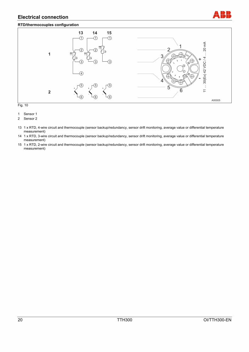
Transmitter design: II 3G EEx nA II T6
Explosion-protection zone 2 Safety area
B C
A00148
A
D
Fig. 17 A Sensor
B Transmitters in housing with IP54 level of protection
C Power supply
D HMI interface for LCD displays (activation is possible as an option only when ordering)
For instruments in zone 2, the transmitter must be installed in its own housing with IP54 level of protection. Ensure that in case of a disturbance the supply voltage cannot exceed 40% of the normal voltage.
Startup Operation
28 TTH300 OI/TTH300-EN
6 Startup Operation
Note
The transmitter is immediately ready for operation after mounting and installation of the connections. The parameters are set at the factory.
The connected wires must be checked for firm seating. Only firmly seated wires ensure full functionality.
K
7 Communication and configuration
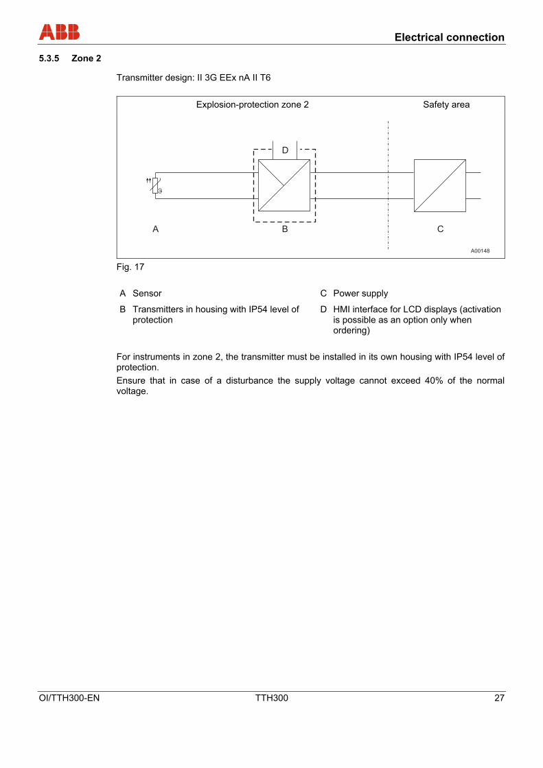
7.1 Configurations
Transmitters can be configured as follows:
• via HART protocol and handheld terminal
• via HART protocol with FSK modem, PC and SmartVision configuration software.
• via DTM in FDT1.2 network applications
• Configuration via field bus (Profibus), if the superordinate I/O system is HART-enabled (e.g., ABB S800 or S900)
Optional: Configuration via plug-on LCD display using the control buttons
* if necessary
Fig. 18
1 DHH691 (691HT), STT04, HC275, FC375
2 FDT/DTM technology
3 Power supply (process interface)
7.1.1.1 HART communication
Communication with the transmitter is supported by the HART protocol. The communication signal is modulated onto both wires of the signal line according to the HART FSK “Physical Layer” specification, version 8.1 (08/1999). The electrical connection is provided either by two test pins at the (+) and (–) terminals of the transmitter or by the power supply cable that is installed on-site. The advantage is that power supplies that are part of the industrial plant allow remote configuration.

Communication and configuration
OI/TTH300-EN TTH300 29
7.1.1.2 Configuration with the handheld terminal
The configuration with the handheld terminal normally takes place at the factory before the installation of the transmitter in an industrial plant.
1. Open the housing of the head-mounted measuring inset.
2. Carefully clamp both test tips of the separate operating control on the contacts in the slotting in front of the + and – connection terminals.
3. Be sure the test terminals are firmly seated.
4. The installation is to be realized according to the figure in the “Configuration types” paragraph.
Note
The connection of the test tips is performed without polarity. Thus, it does not make a difference which test tip is clamped to which + or – connection terminal.
The configuration of the transmitter via the HART protocol can also take place during the normal operation.
7.1.1.3 Configuration via DTM
Configuration can be performed with any FDT network applications that are approved for use with the DTM (e.g., Smart Vision). The bus can be connected via FSK modem as well as HART + USB, Profibus + remote I/O or HART Multiplexer.
7.1.1.4 Configuration via EDD
Configuration can also be performed with EDD master applications such as Siemens Simatic, which is approved for use with EDD. In contrast to DTM configuration, EDD has process-dependent, minor limitations such as configuration of a freestyle characteristic.
7.1.1.5 Optional: Configuration via the LCD display with the control buttons
During operation, the name of the measuring site of the flowmeter primary (TAG no.) and the reading are shown on the LCD display (see section 15).
Note
In contrast to the SmartVision software, the functionality of the transmitter with the LCD display and the control buttons is only partially changeable.
The configuration of the transmitter parameters is described in the “Configuration with the LCD display and the control buttons” paragraph in this manual.

Communication and configuration
30 TTH300 OI/TTH300-EN
7.1.2 Configuration via the LCD display and the control buttons (optional model only)
The configuration of the transmitter is done using the buttons below the LCD display on the front side of the housing. The buttons and the LCD display are in a protected location under the housing cover with inspection glass.
A00104
5
6
4
3
2
1
Fig. 19
1 Diagnostic
2 Bar graph
3 Readout
4 HART tag
5 Unit
6 Optional: bar graph in % of configured measuring range

Communication and configuration
OI/TTH300-EN TTH300 31
7.1.3 Menu navigation
Fig. 20 • The (1), (4), (2) und (3) buttons are available for the menu-controlled configuration.
• The menu/submenu designation is displayed above in the LCD display.
• The number/line of the currently selected menu item is displayed in the upper right of the LCD display.
• A scroll bar is located on the right edge of the LCD display which shows the relative position of the currently selected menu item within the menu.
• Both of the and buttons can have various functions assigned to them. The meaning of these buttons is displayed below in the LCD display above the respective button. The following functions are possible.
Button functions Meaning
Exit Exit menu.
Back Back one submenu.
Cancel Exit without saving the selected parameter value.
Next Select next digit for entering numerical values. Button functions Meaning
Select Select submenu/parameter.
Edit Edit parameter.
OK Save selected parameter and display stored parameter value.
• You can browse through the menu or select a number within a parameter value using both
or buttons. The button selects the desired menu item.
• You can exit a parameter, a submenu or the main menu at any time using the button.

Communication and configuration
32 TTH300 OI/TTH300-EN
7.1.3.1 Calling up the menu
Fig. 21
1 Entering the menu 1. First, the transmitter voltage supply must be switched on. The “ABB connecting …“ display
appears after a few seconds. The “Primary VAL“ value is subsequently displayed.
2. A symbol for calling up the menu is located in the LCD display above the button. By pressing the button, the configuration menu is called up. The “Config Device” main menu is displayed.
7.1.3.2 Selecting a menu item/parameter
• The desired submenu must be selected if the menu contains submenus.
• You can only then select a parameter when the corresponding submenu contains configurable parameters e.g. “Sensor type”.
7.1.3.3 Configuring a parameter value
1. If a parameter in a submenu is selected, the current configurable parameter value is displayed.
2. By pressing the “Edit“ button, either all configurable parameter values or a numerical value to be set are displayed. The currently configured parameter value is highlighted.
Using the “HART tag“ example, the alphanumeric operation is also possible. The character position of the tag no. is determined with the button. The corresponding character can be selected from the character set with the and buttons.
Fig. 22

Communication and configuration
OI/TTH300-EN TTH300 33
7.1.4 Example of configuration changes
Output configuration (standard)
Input sensor 1 / sensor type: PT100 IEC751
Measuring range: 0 … 100 °C
Connection type: 3-wire connection
Fault signaling: Override / 22 mA
Damping: Off / 0s
Write Protection: disabled
Configuration to be set:
Input sensor 1 / sensor type: Thermocouple type K
Measuring range: 0 ... 1000 °C
Reference point: internal
Fault signaling: Override / 22 mA
Damping: Off / 0s
Write Protection: activated
Procedure:
Fig. 23 1. Press the button to call up the main menu.
2. Use the (2) and (3) buttons to mark “Config Device” and confirm via (4).
3. Select “Input Sensor 1” and confirm via (4).
4. In the submenu “Input Sensor 1” select the sensor type.
5. Use the (2) or (3) buttons to select and confirm “TC Type K (IEC 584)”.
6. “Back” via the (1) button in the submenu “Input Sensor 1” and menu item “Reference Point”.
Since “internal” is set at the factory, no change is required here.
7. Exit “Reference Point” and return to the menu item “Config. Device” via the (1) button.
8. Select the subitem “Measuring Range”.

Communication and configuration
34 TTH300 OI/TTH300-EN
9. In the subitem “Measuring Range”, select the function “Upper Range Value”.
The currently configured URL (100 °C) is displayed.
10. The (4) “Edit” button can be used to edit the URL. Use the (1) button to select the individual numbers of the URL and edit these via the (2) or (3) buttons.
Note
When changing the LRL or URL, use the (1) to select the digit position with the current decimal point. The digit position can be changed so that no decimal point appears at this position before the decimal point is set at another position. If no decimal point is set at another digital position, it can be selected after selecting the digit position by using the (1) button with the button (2) or (3) before or after the configurable digits 0 to 9.
7.2 Activating write protection
1. Confirm “Config Device” via (4) and select “Write Protection”. Displays the current write protection setting.
2. Use the (4) “Edit” button to edit the current write protection configuration.
3. Use the buttons (2) or (3) to select up to max. 4 alphanumeric characters and confirm via the (4) button.
Note
Spaces and the number combination 0110 cannot be entered.
4. Write protection “YES” is displayed.
Click the (1) button three times to exit the configuration mode and display “Reading Display Mode”
7.3 Deactivating write protection
Access the write protection edit mode according to the example.
In the write protection edit mode, an alphanumeric character chain is displayed.
1. Master password “0110” entered
2. Use the (4) “OK” button to confirm.
The information “Write protection NO” is displayed.
Note The master password for deactivating write protection cannot be changed.

Communication and configuration
OI/TTH300-EN TTH300 35
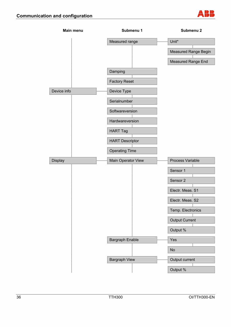
7.3.1.1 Menu structure
The parameters are structured as a menu. The menu consists of a maximum of three levels. Menu items with the * have additional parameters that are called up in the next section.
Main menu Submenu 1 Submenu 2
Device Config Write Protect Yes / Set Password ≠ “0110“
No / Set Password = “0110“
Input Sensor 1 Sensortype*
R-Connection*
2-wire Resistance
Thermocouple RJ*
ext. RJ Temperature
Input Sensor 2 Sensortype*
R-Connection*
2-wire Resistance
Thermocouple RJ*
ext. RJ Temperature
In-output Assignment Sensor 1
Sensor 2
Difference (S1-S2)
Difference (S1-S2)
Mean value
Redundancy
Electr. Meas. S1
Electr. Meas. S2
Temp. Electronics
Communication and configuration
36 TTH300 OI/TTH300-EN
Main menu Submenu 1 Submenu 2
Measured range Unit*
Measured Range Begin
Measured Range End
Damping
Factory Reset
Device info Device Type
Serialnumber
Softwareversion
Hardwareversion
HART Tag
HART Descriptor
Operating Time
Display Main Operator View Process Variable
Sensor 1
Sensor 2
Electr. Meas. S1
Electr. Meas. S2
Temp. Electronics
Output Current
Output %
Bargraph Enable Yes
No
Bargraph View Output current
Output %
Communication and configuration
OI/TTH300-EN TTH300 37
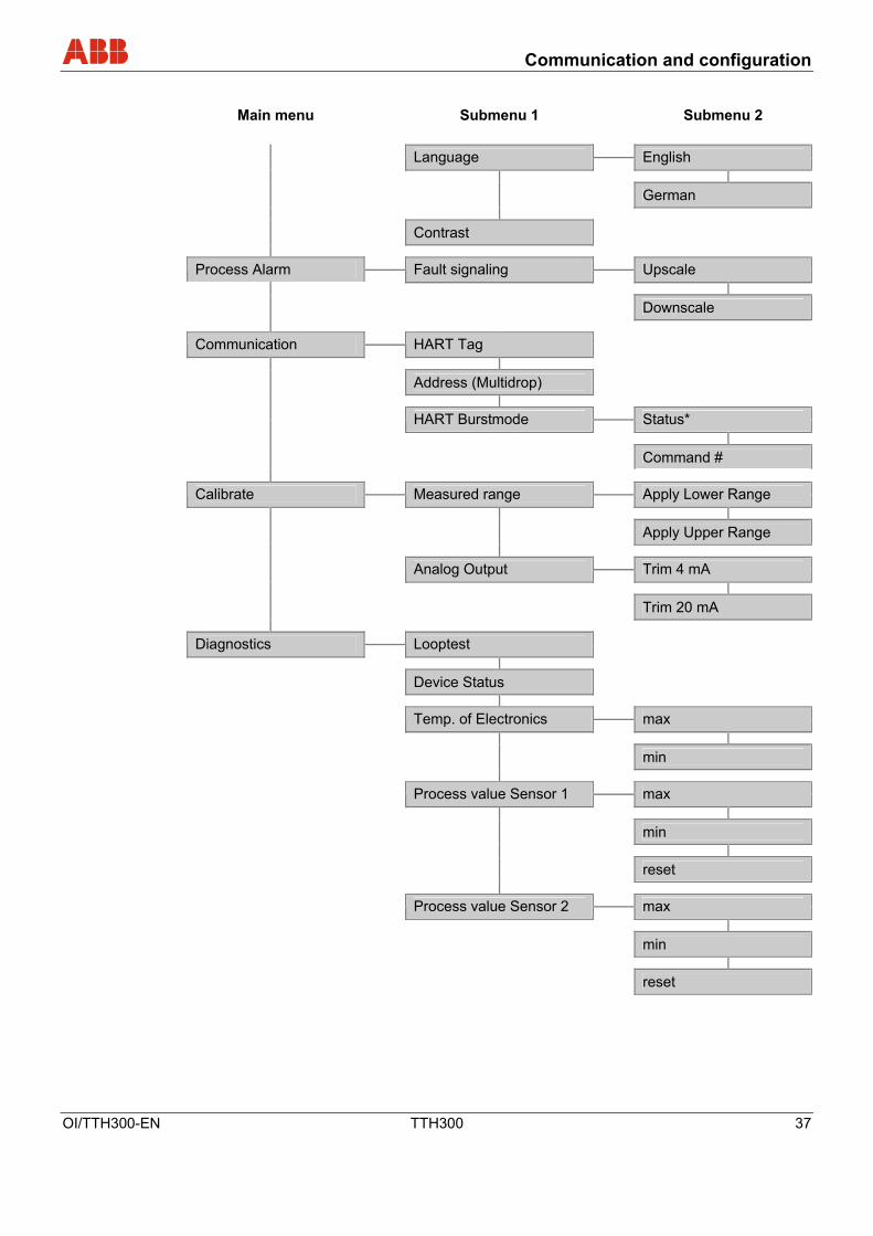
Main menu Submenu 1 Submenu 2
Language English
German
Contrast
Process Alarm Fault signaling Upscale
Downscale
Communication HART Tag
Address (Multidrop)
HART Burstmode Status*
Command #
Calibrate Measured range Apply Lower Range
Apply Upper Range
Analog Output Trim 4 mA
Trim 20 mA
Diagnostics Looptest
Device Status
Temp. of Electronics max
min
Process value Sensor 1 max
min
reset
Process value Sensor 2 max
min
reset

2-sensor input functionality / Dual sensor mode
38 TTH300 OI/TTH300-EN
8 2-sensor input functionality / Dual sensor mode
8.1 2-HART measurement signals
According to the “Connection diagrams” section, equivalent RTD or thermocouple sensors or combinations of both can be attached to the transmitter inputs.
Remote I/O systems such as ABB S900 read out these HART variables on a cyclic basis and provide them to the control system in the form of cyclic process data.
The 4 … 20 mA analog output maps only on sensor value. Users can choose to map sensor value 1 or sensor value 2, the differential based on both, or the average. The value mapped is specified during transmitter configuration, e.g., LCD display in the menu “Config. Device” / submenu “Input/output Assignment”.
8.2 Redundancy / sensor backup
Use two sensors and sensor redundancy mode to increase system uptime.
If sensor 1 fails, the output signal switches bumplessly within the cyclic refresh rate to sensor 2.
In addition, a HART diagnostic message is generated in accordance with Namur NE 107 “Maintenance required / Sensor wire break”.
If redundant sensor 2 fails, a HART signal diagnostic notification is generated.
To minimize the effect on the output signal and increase accuracy in case of a sensor wire break, the average of both sensors is mapped to the analog output in redundancy mode as long as both sensors are available.
Sensor or device failure fault signaling at the analog output signal as required per Namur NE43 / NE107 ensures that the transmitter is capable of signaling "Maintenance required” diagnostic information via HART signal as well as analog signal, using overranging (22 mA) and underranging (3.6 mA).
The signaling of “Maintenance required” diagnostic information according to NE107 when operating with normal 4 … 20 mA analog output is provided by superimposing pulses.
Depending on fault signaling, for 22 mA overload configuration the 4 … 20 mA signal is superimposed on positive 22 mA pulses or with 3.6 mA underload configuration negative 3.6 mA pulses.
The following values can be configured via pulse width parameters: - A pulse width of 0.5 s … 59.5 s (increment 0.5 s) - Continuous pulse - No diagnostic signaling per pulse on the analog output
The specified pulse width refresh rate is 60 seconds.
2-sensor input functionality / Dual sensor mode
OI/TTH300-EN TTH300 39
4
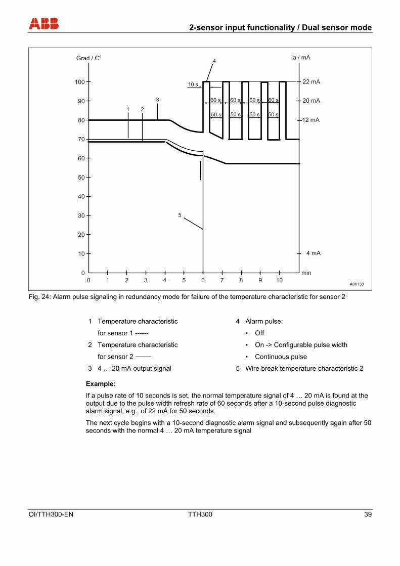
5
Fig. 24: Alarm pulse signaling in redundancy mode for failure of the temperature characteristic for sensor 2
1 Temperature characteristic
for sensor 1 ------
2 Temperature characteristic
for sensor 2
3 4 … 20 mA output signal
4 Alarm pulse:
• Off
• On -> Configurable pulse width
• Continuous pulse
5 Wire break temperature characteristic 2
Example:
If a pulse rate of 10 seconds is set, the normal temperature signal of 4 … 20 mA is found at the output due to the pulse width refresh rate of 60 seconds after a 10-second pulse diagnostic alarm signal, e.g., of 22 mA for 50 seconds.
The next cycle begins with a 10-second diagnostic alarm signal and subsequently again after 50 seconds with the normal 4 … 20 mA temperature signal

2-sensor input functionality / Dual sensor mode
40 TTH300 OI/TTH300-EN
8.3 Sensor drift detection
When two sensors are connected, an optional sensor drift detection can be activated in redundancy mode, 2-HART measurement signal mode and during averaging.
Activation or configuration of sensor drift detection and analog diagnostic signaling (previously described) can only be performed using TTH300 DTM configuration or EDD-based tools.
Sensor drift detection can be activated for the following two sensor types (for connection diagrams, refer to section 5.5):
- 2 x RTD 2-wire circuit
- 2 x RTD 3-wire circuit
- 2 x resistance measurement / potentiometer 2-wire circuit
- 2 x resistance measurement / potentiometer 3-wire circuit
- 2 x thermocouple
- 2 x voltage measurement
- 1x Pt100 2-wire circuit and thermocouple
- 1x Pt100 3-wire circuit and thermocouple
- 1x Pt100 4-wire circuit and thermocouple
To activate sensor drift detection, the transmitter must first be configured for the abovementioned sensor types. Then the maximum allowable sensor deviation must be configured (e.g., max. 1 °C).
Based on possible marginally different sensor response times, a limit must subsequently be set during which time the sensor deviation must be continuously larger than the max. sensor drift differential value defined at max. 1°C.
If the transmitter records a larger sensor deviation during the defined time period, a HART diagnostic notification “Maintenance required” is generated according to NE107. In addition, diagnostic information is displayed in the LCD display below the measurement value: “Maintenance required” is indicated by an “M” and the error code is also displayed, see section 9 Error messages.
The “Maintenance required” diagnostic information related to sensor drift detection can be signaled as in the event of a sensor failure in redundancy mode as well as pulse alarm signal superimposed on the 4 … 20 mA analog signal as described in further detail in the section on redundancy.
If drift monitoring is used for equivalent sensors (2 x Pt100 or 2 x TC), the average from both sensors is basically mapped to the analog output in redundancy mode.
If a thermocouple is used for Pt100 drift monitoring, the Pt100 sensor (see section 5.5 Connection diagrams) must be connected to channel 1 and the thermocouple sensor to channel 2.
The measurement value from channel 1 (Pt100) is basically mapped at the analog output.
Note Before configuring the max. allowable sensor deviation for drift detection, it is recommended that you use the TTH300 DTM to align sensor channel 2 with sensor channel 1.

2-sensor input functionality / Dual sensor mode
OI/TTH300-EN TTH300 41
A00135
Fig. 25: Alarm pulse signaling during sensor drift overshoot
1 Temperature characteristic for
sensor 1 ------
2 Temperature characteristic for
sensor 2
3 4 … 20 mA output signal
4 max. sensor drift differential (e.g. Δ > 1 °C)
5 Alarm pulse:
• Off
• On -> Configurable pulse width
• Continuous pulse
6 Sensor drift detection time period (e.g., 2 min.)

2-sensor input functionality / Dual sensor mode
42 TTH300 OI/TTH300-EN
8.4 Sensor error adjustment (TTH300 DTM Adjust function / in HMI LCD display Calibrate function)
Sensor error adjustment can be performed in the TTH300 DTM by navigating to Device / Maintenance / Adjust / Trim low or Trim high.
For sensor error adjustment, the sensor connected to the transmitter must be brought to the temperature at measurement start / trim low via water quench or oven. It is important to make sure the temperature is balanced and stable.
In the DTM or LCD configuration software, check that the proper adjustment temperature has been entered for the sensor before adjusting the sensor.
Based on the configured adjustment temperature (setpoints) and the digital temperature measured by the transmitter, which is available after linearization in the form of HART temperature information, the transmitter calculates the temperature deviation resulting from the sensor error.
The temperature deviation calculated results during single point adjustment in an offset shift of the linear characteristic output by the linearization module; the values correspond to the HART signal or are sent to the current output.
A sensor error two-point adjustment results in a change of the offset and gradient due to the linear temperature value characteristic output by the linearization module.
A pure sensor offset error can be corrected via the function “Set Measurement Start” or the adjustment function “Trim low”. A non-exclusively sensor offset error can, on the other hand, be corrected only with a two-point adjustment or two-point calibration.
If you enter the temperature value for sensor 1 when adjusting for sensor error on channel 2, then channel 2 is adjusted to the temperature value of sensor 1.
This can occur at a single point (one-point adjustment – sensor – offset – underpressure) as well as at two points (two-point adjustment – sensor – offset and gradient correction).
8.5 D/A analog output compensation (4 and 20 mA trim)
Output compensation is used to correct errors in the power input of the superordinate system.
Analog output compensation for the transmitter can be used to modify the loop current so that the desired value is displayed in the superordinate system.
Error compensation for the superordinate system is possible at the LRL with 4 mA or 20 mA. (Single point error correction: Offset or two-point error correction offset + linear gradient)
D/A analog output compensation can be accessed in the HMI LCD display via the menu path Calibrate / Analog Output / Trim 4/20mA or via TTH300 DTM via the path Device / Maintenance / Adjust.
Prior to analog compensation, it is necessary to determine the loop current values based on iterative entry of current data in simulation mode; the superordinate I/O system displays exactly 4,000 mA, the LRL or 20,000 mA and the URL temperature. Measure loop current data using an ammeter and record the values.
Simulate the LRL or 4,000 mA +/- 16µA in D/A analog output compensation mode using sensor simulation. Thereafter, enter the iteratively measured current at which the superordinate system displays exactly 4,000 mA or the LRL as adjustment value. Proceed in a similar manner for the URL or 20,000 mA.
The disadvantage of D/A analog output compensation is that the HART signal prior to the D/A conversion without correction differs from the analog output signal after D/A conversion due to the incoming error correction of the superordinate system. As a result, the HART value displayed is slightly different from the output signal current.
2-sensor input functionality / Dual sensor mode
OI/TTH300-EN TTH300 43
8.6 HART variable assignment
Since HART devices can basically transmit four variables, the measurement value to be transmitted via HART signal can be specified in the menu Device / Configuration when using the TTH300 DTM or EDD for device setup.
The primary variable is mapped to the 4 … 20 mA output as well as the secondary, tertiary and quaternary variables.
The following values can be assigned to variables:
- Elec. input 1
- Elec. input 2
- Sensor 1 process data
- Sensor 2 process data
- Differential sensor 1 – sensor 2
- Differential sensor 2 – sensor 1
- Average of sensor 1 + sensor 2
- Redundancy
- Electronic unit temperature
8.7 Communication / HART tag / Device address
For ease of identification, each HART device features a configurable 8-digit HART tag. Standard devices are come with the HART tag “TI XXX”.
(When storing HART tags with more than 8 digits in the device, use the “Report” parameter, which supports up to 30 characters.)
In addition to the HART tag, each device has a HART address.
This address is set by default to zero, in which state the device operates in HART standard communication mode (point-to-point operation). When an address in the range 1 to 15 is used, the device switches to HART multidrop mode. This operating mode enables users to connect up to 15 devices in parallel to a power supply.
In multidrop mode, an analog output signal that matches the process temperature is not available. The output signal in multidrop mode is, basically, a constant 4 mA and is used exclusively for the power supply.
In multidrop mode, sensor or process data information is available only as a HART signal.
In addition to point-to-point and multidrop modes, the third type of HART communication is burst mode. When burst mode is activated, the device continuously transmits a HART telegram containing reading information approx. every 500 ms without prompting by HART command.
In burst mode as with point-to-point mode, the analog output signal is available and matches the primary variable defined during setup.

2-sensor input functionality / Dual sensor mode
44 TTH300 OI/TTH300-EN
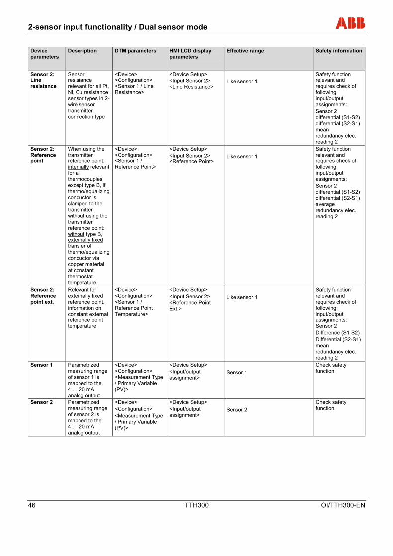
8.8 Description of parameters
Device parameters
Description DTM parameters HMI LCD display parameters
Effective range Safety information
HMI Yes: Password:
locked ≠ 0110
Write protection
Activates write protection for the entire device.
<Basic Parameters> <General> <Write Protection>
<Device Setup> <Write Protection> <Password>
No: Enter password:
unlocked 0110
Must be locked to ensure safety function.
Sensor 1: Sensor model
Select sensor type:
<Device> <Configuration> <Sensor 1 / Sensor Type>
<Device Setup> <Input sensor 1> <Sensor Type>
Pt100 (IEC751) Pt1000 (IEC751) Thermocouple type K (IEC584) Thermocouple type B (IEC584) Thermocouple type C (ASTME988) Thermocouple type D (ASTME988) Thermocouple type E (IEC584) Thermocouple type J (IEC584) Thermocouple type N (IEC584) Thermocouple type R (IEC584) Thermocouple type S (IEC584) Thermocouple type T (IEC584) Thermocouple type L (DIN43710) Thermovoltage – 125…125 mV Thermovoltage – 125…1100 mV Resistance 0….500 Ω Resistance 0….5000 Ω Pt10 (IEC751) Pt50 (IEC751) Pt200 (IEC751) Pt500 (IEC751) Pt10 (JIS1604) Pt50 (JIS1604) Pt200 (JIS1604) Pt10 (IMIL24388) Pt50 (IMIL24388) Pt100 (MIL24388) Pt200 (MIL24388) Pt1000 (MIL24388) Ni50 (DIN43760) Ni100 (DIN43760) Ni120 (DIN43760) Ni1000 (DIN43760) Cu10 (a=4270) Cu100 (a=4270) Fixpoint-Tabl. 1 Fixpoint-Tabl. 2 Fixpoint-Tabl. 3 Fixpoint-Tabl. 4 Fixpoint-Tabl. 5 Combisensor Cal. Van Dusen 1 Cal. Van Dusen 2 Cal. Van Dusen 3 Cal. Van Dusen 4 Cal. Van Dusen 5
Check safety function
Sensor 1: Type of connection
Sensor connection type relevant for all Pt, Ni, Cu resistance sensor types
<Device> <Configuration> <Sensor 1 / Connection>
<Device Setup> <Input sensor 1> <Connection Type>
2-wire 3-wire 4-wire
Check safety function

2-sensor input functionality / Dual sensor mode
OI/TTH300-EN TTH300 45
Device parameters
Description DTM parameters HMI LCD display parameters
Effective range Safety information
Sensor 1: Line resistance
Sensor resistance relevant for all Pt, Ni, Cu resistance sensor types in 2-wire sensor transmitter connection type
<Device> <Configuration> <Sensor 1 / Line Resistance>
<Device Device> <Input Sensor 1> <Line Resistance>
0 … max. 100 Ω Check safety function
Sensor 1: Reference point
When using the transmitter reference point: internally relevant for all thermocouples except type B, if thermo/ equalizing conductor is clamped to the transmitter without using the transmitter reference point: without type B, externally fixed transfer of thermo/ equalizing conductor via copper material at constant thermostat temperature
<Device> <Configuration> <Sensor 1 / Reference Point>
<Device Device> <Input Sensor 1> <Reference Point>
internal without externally - fixed
Check safety function
Sensor 1: Reference point ext.
Relevant for external reference point, information on constant external reference point temperature
<Device> <Configuration> <Sensor 1 / Reference Point Temp.>
<Device Device> <Input Sensor 1> <Reference Point Ext.>
-50 ...100°C Check safety function
Sensor 2: Sensor model
Select sensor type:
<Device> <Configuration> <Sensor 2 / Sensor Type>
<Device Setup> <Input Sensor 2> <Sensor Type>
Like sensor 1 Safety function relevant and requires check of following input/output assignments: Sensor 2 Differential (S1-S2) Differential (S1-S2) Mean Redundancy Elec. reading 2
Sensor 2: Type of connection
Sensor connection type relevant for all Pt, Ni, Cu resistance sensor types
<Device> <Configuration> <Sensor 2 / Connection>
<Device Setup> <Input Sensor 2> <Connection Type>
Like sensor 1 Safety function relevant and requires check of following input/output assignments: Sensor 2 Differential (S1-S2) Differential (S2-S1) Mean Redundancy Elec. reading 2
2-sensor input functionality / Dual sensor mode
46 TTH300 OI/TTH300-EN
Device parameters
Description DTM parameters HMI LCD display parameters
Effective range Safety information
Sensor 2: Line resistance
Sensor resistance relevant for all Pt, Ni, Cu resistance sensor types in 2-wire sensor transmitter connection type
<Device> <Configuration> <Sensor 1 / Line Resistance>
<Device Setup> <Input Sensor 2> <Line Resistance>
Like sensor 1 Safety function relevant and requires check of following input/output assignments: Sensor 2 differential (S1-S2) differential (S2-S1) mean redundancy elec. reading 2
Sensor 2: Reference point
When using the transmitter reference point: internally relevant for all thermocouples except type B, if thermo/equalizing conductor is clamped to the transmitter without using the transmitter reference point: without type B, externally fixed transfer of thermo/equalizing conductor via copper material at constant thermostat temperature
<Device> <Configuration> <Sensor 1 / Reference Point>
<Device Setup> <Input Sensor 2> <Reference Point>
Like sensor 1 Safety function relevant and requires check of following input/output assignments: Sensor 2 differential (S1-S2) differential (S2-S1) average redundancy elec. reading 2
Sensor 2: Reference point ext.
Relevant for externally fixed reference point, information on constant external reference point temperature
<Device> <Configuration> <Sensor 1 / Reference Point Temperature>
<Device Setup> <Input Sensor 2> <Reference Point Ext.>
Like sensor 1 Safety function relevant and requires check of following input/output assignments: Sensor 2 Difference (S1-S2) Differential (S2-S1) mean redundancy elec. reading 2
Sensor 1 Parametrized measuring range of sensor 1 is mapped to the 4 … 20 mA analog output
<Device> <Configuration> <Measurement Type / Primary Variable (PV)>
<Device Setup> <Input/output assignment>
Sensor 1 Check safety function
Sensor 2 Parametrized measuring range of sensor 2 is mapped to the 4 … 20 mA analog output
<Device> <Configuration> <Measurement Type / Primary Variable (PV)>
<Device Setup> <Input/output assignment>
Sensor 2 Check safety function
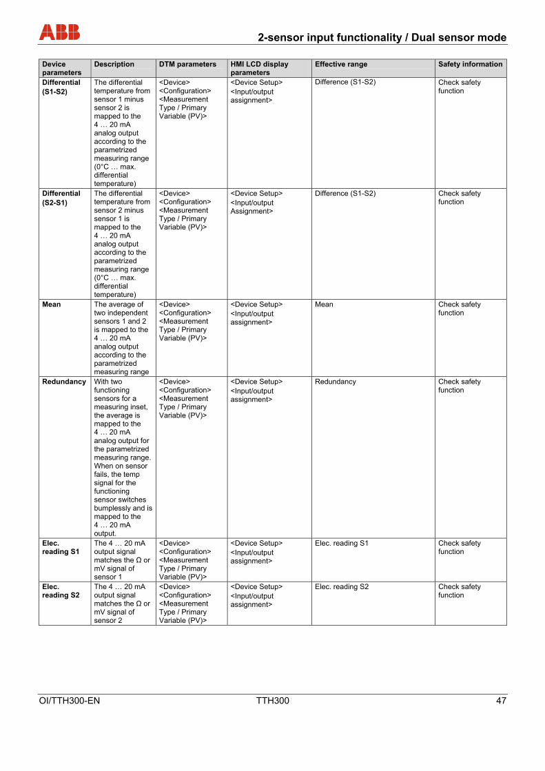
2-sensor input functionality / Dual sensor mode
OI/TTH300-EN TTH300 47
Device parameters
Description DTM parameters HMI LCD display parameters
Effective range Safety information
Differential (S1-S2)
The differential temperature from sensor 1 minus sensor 2 is mapped to the 4 … 20 mA analog output according to the parametrized measuring range (0°C … max. differential temperature)
<Device> <Configuration> <Measurement Type / Primary Variable (PV)>
<Device Setup> <Input/output assignment>
Difference (S1-S2) Check safety function
Differential (S2-S1)
The differential temperature from sensor 2 minus sensor 1 is mapped to the 4 … 20 mA analog output according to the parametrized measuring range (0°C … max. differential temperature)
<Device> <Configuration> <Measurement Type / Primary Variable (PV)>
<Device Setup> <Input/output Assignment>
Difference (S1-S2) Check safety function
Mean The average of two independent sensors 1 and 2 is mapped to the 4 … 20 mA analog output according to the parametrized measuring range
<Device> <Configuration> <Measurement Type / Primary Variable (PV)>
<Device Setup> <Input/output assignment>
Mean Check safety function
Redundancy With two functioning sensors for a measuring inset, the average is mapped to the 4 … 20 mA analog output for the parametrized measuring range. When on sensor fails, the temp signal for the functioning sensor switches bumplessly and is mapped to the 4 … 20 mA output.
<Device> <Configuration> <Measurement Type / Primary Variable (PV)>
<Device Setup> <Input/output assignment>
Redundancy Check safety function
Elec. reading S1
The 4 … 20 mA output signal matches the Ω or mV signal of sensor 1
<Device> <Configuration> <Measurement Type / Primary Variable (PV)>
<Device Setup> <Input/output assignment>
Elec. reading S1 Check safety function
Elec. reading S2
The 4 … 20 mA output signal matches the Ω or mV signal of sensor 2
<Device> <Configuration> <Measurement Type / Primary Variable (PV)>
<Device Setup> <Input/output assignment>
Elec. reading S2 Check safety function

2-sensor input functionality / Dual sensor mode
48 TTH300 OI/TTH300-EN
Device parameters
Description DTM parameters HMI LCD display parameters
Effective range Safety information
Temp. electronics
The 4 ... 20 mA output signal matches the electronic unit temperature
<Device> <Configuration> <Measurement Type / Primary Variable (PV)>
<Device Setup> <Input/output assignment>
Temp. electronics Check safety function
Unit Select the unit of measure for the sensor
<Device> <Parametrize> <Measuring Range of PV / Unit>
<Device Setup> <Measuring Range> <Unit>
°C, °F, °R, K, user, mV, Ω, mA Depending on sensor type
Measurement start
Defines the sensor measurement start
<Device> <Parametrize> <Measuring Range of PV / Lower Range Value>
<Device Setup> <Measuring Range> <Lower Range Value>
Depending on sensor type Depending on sensor type
Measurement end
Defines the sensor measurement end
<Device> <Parametrize> <Measuring Range of PV / Upper Range Value>
<Device Setup> <Measuring Range> <Upper Range Value>
Depending on sensor type Depending on sensor type
Damping Configurable condensation 63% output signal damping value
<Device > <Parametrize> <Voltage Output / Damping>
<Device Setup> <Damping>
0 ... 100 s Depending on sensor type
Factory reset
Configuration data is reset to factory settings for Pt100 3-wire, 0 ... 100°C damping off, override, adjustment data (trim high/low and DAC adjustment values are reset to factory settings)
<Device> <Maintenance> <Reset to Factory Setting>
<Device Setup> <Factory Setting>
Yes / OK Safety function for potential risk all configuration and adjustment data are reset to the factory default
Device reset
Configuration data is reset to factory setting for Pt100 3-wire, 0 … 100°C damping off, override
<Device> <Maintenance> <Device Reset>
Safety function for potential risk configuration data is reset to the factory default
Override Generates a 22 mA high alarm signal for sensor or device errors
<Device> <Parametrize> <Current Output / Output with Fault>
<Process Alarm> <Fault Signaling>
Override Check safety function
underranging Generates a 3.6 mA low alarm signal for sensor or device errors
<Device> <Parametrize> <Current Output / Output with Fault>
<Process Alarm> <Fault Signaling>
underdrive Check safety function
HART tag Defines HART tag name
<Device> <Maintenance> <Poll Address / Tag>
<Communication> <HART Tag>
8 characters, alphanumeric Check safety function
2-sensor input functionality / Dual sensor mode
OI/TTH300-EN TTH300 49
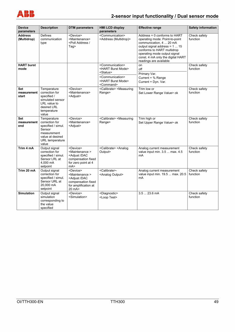
Device parameters
Description DTM parameters HMI LCD display parameters
Effective range Safety information
Address (Multidrop)
Defines communication type
<Device> <Maintenance> <Poll Address / Tag>
<Communication> <Address (Multidrop)>
Address = 0 conforms to HART operating mode: Point-to-point communication, 4 ... 20 mA output signal address = 1 ... 15 conforms to HART multidrop operating mode output signal const. 4 mA only the digital HART readings are available
Check safety function
HART burst mode
<Communication> <HART Burst Mode> <Status> <Communication> <HART Burst Mode> <Command>
on off Primary Var. Current + % Range Current + Dyn. Var.
Check safety function
Set measurement start
Temperature correction for specified / simulated sensor LRL value to desired LRL temperature value
<Device> <Maintenance> <Adjust>
<Calibrate> <Measuring Range>
Trim low or Set Lower Range Value> ok
Check safety function
Set measurement end
Temperature correction for specified / simul. Sensor measurement value at desired URL temperature value
<Device> <Maintenance> <Adjust>
<Calibrate> <Measuring Range>
Trim high or Set Upper Range Value> ok
Check safety function
Trim 4 mA Output signal correction for specified / simul. Sensor LRL at 4,000 mA setpoint
<Device> <Maintenance > <Adjust /DAC compensation fixed for zero point at 4 mA>
<Calibrate> <Analog Output>
Analog current measurement value input min. 3.5 ... max. 4.5 mA
Check safety function
Trim 20 mA Output signal correction for specified / simul. Sensor URL at 20,000 mA setpoint
<Device> <Maintenance > <Adjust /DAC compensation fixed for amplification at 20 mA>
<Calibrate>- <Analog Output>
Analog current measurement value input min. 19.5 ... max. 20.5 mA
Check safety function
Simulation Output signal simulation corresponding to the value specified
<Device> <Simulation>
<Diagnostic> <Loop Test>
3.5 ... 23.6 mA Check safety function

2-sensor input functionality / Dual sensor mode
50 TTH300 OI/TTH300-EN
Device parameters
Description DTM parameters HMI LCD display parameters
Effective range Safety information
For software version SW 01.01.03 or higher: Drift detection: enabled
activated Sensor drift detection
<Device > <Parametrize> <enabled>
on off
Check safety function
Drift detection: max. sensor differential
Value at which sensor drift signaling occurs, if overshoot is longer than the limit time period is present
<Device > <Parametrize> <Max. Sensor Differential>
... Degrees C; ...°F, ...mV, ... Ohm Check safety function
Drift detection: Sensor drift Limit time period
Time period during which the max. sensor differential must be overshot, before sensor drift signaling occurs
<Device > <Parametrize> <Limit time period>
.....minutes Check safety function
Analog alarm pulse maintenance demand signaling: Response for maintenance need
Analog alarm pulse signaling with configurable pulse width for sensor maintenance needs (e.g., failure of a sensor in redundancy mode or overshoot of max. sensor drift differential)
<Device > <Parametrize> <Output current/ Response for Maintenance Needs>
Off Pulse width: >0....59.5 s continuous
Check safety function
* Safety check is performed acc. to SIL safety information based on the document SM/TTX3X/SIL-DE

2-sensor input functionality / Dual sensor mode
OI/TTH300-EN TTH300 51
8.8.1 Factory settings
The transmitter is preconfigured at the factory. The following tables contain the values of the individual parameters. Menu Designation Parameter Factory setting
Write Protect - No
Sensortype Pt100 (IEC751)
R-Connection 3-wires
Measured Range Begin 0
Measured Range End 100
Unit °C
Device Config
Input Sensor 1
Damping Off
Process Alarm Fault signaling Override 22 mA
Input Sensor 2 Sensortype Off
In-output Assignment - Sensor 1
HART Tag - -
HART Descriptor - TIXXX
Main Operator View - Process Variable
Bargraph Enable - Yes
Bargraph View - Output %
Language - English
Display
Contrast - 50 %
Communication HART Burstmode Status Off

Error messages
52 TTH300 OI/TTH300-EN
9 Error messages
The following list contains the error messages for the LCD display. Device
Status
DIAG.
NO.
Source of Error Error correction
Device F 1 Device defective. Replacing the device.
Device S 2
Above/below ambient temperature.
Check environment, possibly reposition measuring point.
Device F 3 EEPROM defective. Replacing the device.
Device M 4
Electronics overload. Reset to factory settings, notify service of error message.
Device F 5
Memory error. Reset to factory settings, notify service of error message.
Device I 7 HMI inserted. Status info, no error.
Device I 8 Device write-protected. Status info, no error.
Device I 9 EEPROM busy. Status info, no error.
Device F 12 Sensor input defective (communication).
Replacing the device.
Device F 13 Sensor input defective (error).
Replacing the device.
Device F 14 Sensor input defective (ADC error).
Replacing the device.
Communication C 32 Diagnostic simulation mode No error, diagnostic info,
measurement OK.
Sensor
Sensor 1 F 34 Measuring error. Check sensor connection.
Sensor 1 F 35 Sensor short-circuit. Check sensor connection.
Sensor 1 F 36 Wire break. Check sensor connection.
Sensor 1 F 37 Above sensor range. Check measuring limits.
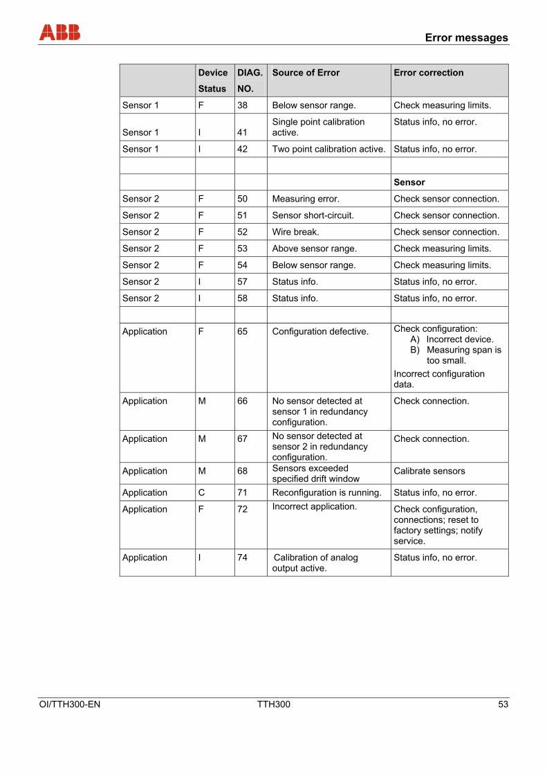
Error messages
OI/TTH300-EN TTH300 53
Device
Status
DIAG.
NO.
Source of Error Error correction
Sensor 1 F 38 Below sensor range. Check measuring limits.
Sensor 1 I 41 Single point calibration active.
Status info, no error.
Sensor 1 I 42 Two point calibration active. Status info, no error.
Sensor
Sensor 2 F 50 Measuring error. Check sensor connection.
Sensor 2 F 51 Sensor short-circuit. Check sensor connection.
Sensor 2 F 52 Wire break. Check sensor connection.
Sensor 2 F 53 Above sensor range. Check measuring limits.
Sensor 2 F 54 Below sensor range. Check measuring limits.
Sensor 2 I 57 Status info. Status info, no error.
Sensor 2 I 58 Status info. Status info, no error.
Application F 65 Configuration defective. Check configuration: A) Incorrect device. B) Measuring span is
too small. Incorrect configuration data.
Application M 66 No sensor detected at sensor 1 in redundancy configuration.
Check connection.
Application M 67 No sensor detected at sensor 2 in redundancy configuration.
Check connection.
Application M 68 Sensors exceeded specified drift window
Calibrate sensors
Application C 71 Reconfiguration is running. Status info, no error.
Application F 72 Incorrect application. Check configuration, connections; reset to factory settings; notify service.
Application I 74 Calibration of analog output active.
Status info, no error.

Error messages
54 TTH300 OI/TTH300-EN
Device
Status
DIAG.
NO.
Source of Error Error correction
Application C 75 Analog output in simulation. Status info, no error.
Application S 76 Above range. Check parameters: A) Above sensor
range. Measuring span is too small.
Application S 77 Limit HIGH HIGH. Upper limit value: Alarm.
Application S 78 Limit LOW LOW. Lower limit value: Alarm
Application S 79 Limit HIGH. Upper limit value: Warning.
Application S 80 Limit LOW. Lower limit value: Warning. Explanations per NE107 Designation Description
I OK or Information
C Check Function
S Off Specification
M Maintenance Required
F Failure

Additional TTH300 DTM diagnostic information
OI/TTH300-EN TTH300 55
10 Additional TTH300 DTM diagnostic information
Configuration changed
Note The transmitter indicates that the parameters or configuration data has changed (HART: Configuration changed flag). After intentional or desired reconfiguration, the notification can be acknowledged via the <Reset> button.
10.1 Long-term monitoring
The transmitter saves the highest and lowest values for the electronic unit temperature as well as readings from sensor 1 and sensor 2 in a failsafe memory (“Drag Indicator”).
Supply voltage Current supply voltage measured at the clamps of the transmitter in volts (+/- 5%).
Max. elec. temp. Highest detected internal temperature in °C that the transmitter was subjected to. This value cannot be reset.
Min. elec. temp. Lowest detected internal temperature in °C that the transmitter was subjected to. This value cannot be reset.
Max. reading for sensors 1-2 Highest reading at sensor 1 or 2. When changing the sensor type (e.g., Pt100 to thermocouple type K), the value is reset automatically.
Min. reading for sensors 1-2 Lowest reading at sensor 1 or 2. When changing the sensor type, the value is reset automatically.
Reset The drag indicators for the sensor readings are reset to the current measurement value.
10.2 Operating hour statistics
Operating Hours Total hours since commissioning that power has been switched on for transmitter.
Operating hours per electronic unit temperature
The operating hours are categorized according to the measured internal temperature of the transmitter. Due to rounding and frequently switching the device on and off, the total of the individual values may differ slightly from the value displayed by the counter for operating hours. Values in the fields on the far left and right display operation of the transmitter outside the specified range. In this event, acknowledged properties of the transmitter might be limited, in particular, with respect to accuracy and service life.

Maintenance / Repair
56 TTH300 OI/TTH300-EN
11 Maintenance / Repair
11.1 General information
For transmitters that are used as intended under normal operation, no maintenance is required.
No on-site repair or replacement of electronic parts is planned.
Warning! Risk of explosion!
Faulty transmitters may not be placed into operation by the user. Repairs must be performed in the production plant.
11.2 Cleaning
When cleaning the exterior of meters, make sure that the cleaning agent used does not corrode the housing surface and the seals.
11.3 Disposal WEEE directive 2002/96/EC and Restriction of the Use of Certain Hazardous Substances (RoHS) directive 2002/95/EC
ABB Automation Products GmbH actively promotes environmental consciousness and has an operational management system in accordance with DIN EN ISO 9001:2000, EN ISO 14001:2004 and OHSAS 18001. Our products and solutions should have minimum impact the environment and on persons during manufacture, storage, transport, use and disposal.
This includes the environmentally friendly use of natural resources. Through its publications ABB conducts an open dialog with the public. With the Electrical and Electronic Equipment Act (ElektroG) in Germany, the European directives 2002/96/EC (WEEE) and 2002/95/EC (RoHs) are translated to national law. ElektroG defines the products that are subject to regulated collection and disposal or reuse in the event of disposal or at the end of their service life. ElektroG also prohibits the marketing of electrical and electronic equipment that contains a specific amount of lead, cadmium, mercury, hexavalent chromium, polybrominated biphenyls (PBB) and polybrominated diphenyl ethers (PBDE) (also known as hazardous substances with restricted uses). The products and solutions provided to you by ABB Automation Products GmbH do not fall within the current scope of the directive on waste from electrical and electronic equipment according to ElektroG. If the necessary components are available on the market, these substances will no longer be used in new product development. If you are using products from ABB that are subject to the restriction of the use of certain hazardous substances, please notify us in order to receive the required product-specific information. The present device is not subject to WEEE-directive 2002/96/EC and the corresponding national laws (in Germany e.g., ElektroG).
Dispose of the product directly in a specialized recycling facility and do not use the communal garbage. Only privately used products may be disposed of in the municipal garbage according to the WEEE directive 2002/96/EC. Proper disposal prevents negative effects on people and the environment, and supports the reuse of valuable raw materials.
If it is not possible to dispose of old equipment properly, ABB Service can accept and dispose of returns for a fee.

Explosion-protection relevant information
OI/TTH300-EN TTH300 57
12 Explosion-protection relevant information
12.1 TTH300-E1… (intrinsically safe) Wechsel ein-auf zweispaltig
Approved for use in zone 0. Designation: • II 1G EEx ia IIC T6 (Zone 0) • II 2 (1) G EEx [ia] ib IIC T6 (zone 1 [0]) • II 2 G (1D) Ex [iaD] ib IIC T6 (zone 1 [20])
Note The Ex or ignition-proof designation is provided on the name plate.
EC prototype test certificate: Refer to PTB 05 ATEX2017 X. Temperature table
Permissible ambient temperature range Temperature class Device category 1
use Device category 2 use
T6 -50 … 44 °C -50 … 56 °C T5 -50 … 56 °C -50 … 71 °C T4 -50 … 84 °C -50 … 85 °C
Wechsel ein-auf zweispaltig
Safety-relevant data Intrinsically safe EEx ia IIC explosion protection Supply circuit Measurement current
circuit / passive transducer (RTD)
Measurement current circuit / active transducer (RTD)
Display interface
Max. voltage Ui = 30 V Uo = 6,5 V Uo = 1,2 V Uo = 6,2 V Short-circuit current Ii = 130 mA Io = 25 mA Io = 50 mA Io = 65,2 mA Max. power Pi = 0,8 W Po = 38 mW Po = 60 mW Po = 101 mW Internal inductance Li = 0,5 mH Li = 0 mH Li = 0 mH Li = 0 mH Internal capacitance Ci = 5 nF Ci = 49 nF Ci = 49 nF Ci = 0 nF Maximum permissible external inductance
Lo= 5 mH Lo = 5 mH Lo= 5 mH
Maximum permissible external capacitance
Co= 1,55 µF Co= 1,05 µF Co= 1,4 µF
Wechsel ein-auf zweispaltig
12.2 TTH300-E2… (nonincendive)
Approved for use in zone 2. Designation: • II 3 G EEx n A II T6
Note The Ex or ignition-proof designation is provided on the name plate.
ABB statement of conformity in accordance with ATEX directive Temperature table
Temperature class Device category 2 use
T6 -50 … 56 °C T5 -50 … 71 °C T4 -50 … 85 °C

Approvals
58 TTH300 OI/TTH300-EN
CSA and FM approvals Intrinsically Safe
FM Class I, Div. 1 + 2, Groups A, B, C, D T6 Class II, Groups E, F, G; Class III Class I, Zone 0, AEx ia IIC T6 Product variant: TTH300-L1 Control drawing: 214832
CSA Class I, Div. 1 + 2, Groups A, B, C, D Class II, Groups E, F, G; Class III Product variant: TTH300-R1 Control drawing: 214825
Nonincendive
FM Class I, Div. 2, Groups A, B, C, D (Class II, Groups E, F, G; Class III Product variant: TTH300-L2 Control drawing: 214830 (IS & non-incendive) Control drawing: 214828 (non-incendive)
CSA Class I, Div. 2, Groups A,B,C,D (Class II, Groups E, F, G; Class III Product variant: TTH300-R2 Control drawing: 214827 (IS & non-incendive) Control drawing: 214895 (non-incendive)
SIL: Functional safety (optional) acc. to IEC 61508. Device with certificate of conformity for use in safety-relevant applications, including SIL Level 2. For additional information, refer to the safety manual for the TTH300/TTF300.
Wechsel ein-auf zweispaltig Approvals
13 Approvals Wechsel ein-auf zweispaltig
CE mark: The TTH300 meets all requirements for the CE mark in accordance with IEC 61326 (2002). Low voltage directive: The TTH300 complies with low voltage directive 73/72/EC. Ignition protection: The TTH300 meets requirements for ATEX, FM and CSA. For additional information, refer to the section "Explosion-protection relevant information").
Wechsel ein-auf zweispaltig
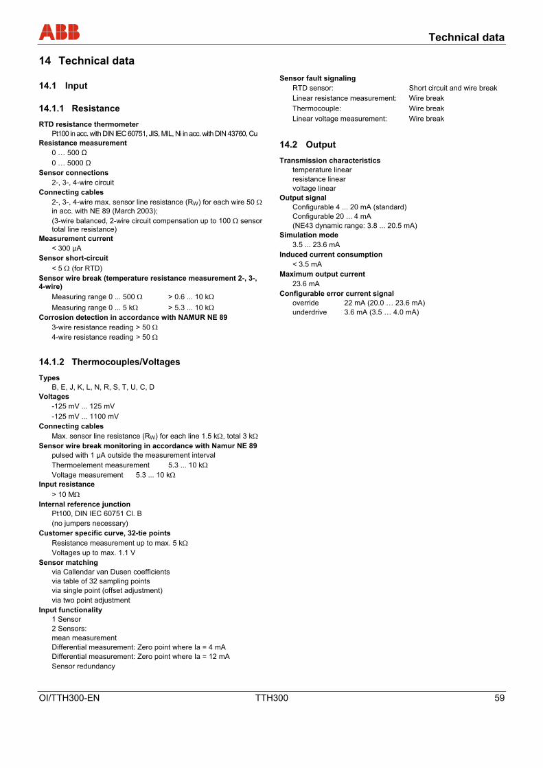
Technical data
OI/TTH300-EN TTH300 59
14 Technical data Wechsel ein-auf zweispaltig
14.1 Input
14.1.1 Resistance
RTD resistance thermometer Pt100 in acc. with DIN IEC 60751, JIS, MIL, Ni in acc. with DIN 43760, Cu
Resistance measurement 0 … 500 Ω 0 … 5000 Ω Sensor connections
2-, 3-, 4-wire circuit Connecting cables
2-, 3-, 4-wire max. sensor line resistance (RW) for each wire 50 Ω in acc. with NE 89 (March 2003); (3-wire balanced, 2-wire circuit compensation up to 100 Ω sensor total line resistance)
Measurement current < 300 µA Sensor short-circuit
< 5 Ω (for RTD) Sensor wire break (temperature resistance measurement 2-, 3-, 4-wire)
Measuring range 0 ... 500 Ω > 0.6 ... 10 kΩ Measuring range 0 ... 5 kΩ > 5.3 ... 10 kΩ
Corrosion detection in accordance with NAMUR NE 89 3-wire resistance reading > 50 Ω 4-wire resistance reading > 50 Ω
14.1.2 Thermocouples/Voltages
Types B, E, J, K, L, N, R, S, T, U, C, D
Voltages -125 mV ... 125 mV -125 mV ... 1100 mV Connecting cables
Max. sensor line resistance (RW) for each line 1.5 kΩ, total 3 kΩ Sensor wire break monitoring in accordance with Namur NE 89
pulsed with 1 µA outside the measurement interval Thermoelement measurement 5.3 ... 10 kΩ Voltage measurement 5.3 ... 10 kΩ
Input resistance > 10 MΩ
Internal reference junction Pt100, DIN IEC 60751 Cl. B (no jumpers necessary)
Customer specific curve, 32-tie points Resistance measurement up to max. 5 kΩ Voltages up to max. 1.1 V
Sensor matching via Callendar van Dusen coefficients via table of 32 sampling points via single point (offset adjustment) via two point adjustment
Input functionality 1 Sensor 2 Sensors: mean measurement Differential measurement: Zero point where Ia = 4 mA Differential measurement: Zero point where Ia = 12 mA Sensor redundancy
Sensor fault signaling RTD sensor: Short circuit and wire break Linear resistance measurement: Wire break Thermocouple: Wire break Linear voltage measurement: Wire break
14.2 Output
Transmission characteristics temperature linear resistance linear voltage linear
Output signal Configurable 4 ... 20 mA (standard) Configurable 20 ... 4 mA (NE43 dynamic range: 3.8 ... 20.5 mA)
Simulation mode 3.5 ... 23.6 mA Induced current consumption < 3.5 mA Maximum output current 23.6 mA Configurable error current signal
override 22 mA (20.0 … 23.6 mA) underdrive 3.6 mA (3.5 … 4.0 mA)

Technical data
60 TTH300 OI/TTH300-EN
14.3 Power supply (polarity safe) Supply voltage
(2-wire technique; power lines = signal lines) Supply voltage
Non ignition-proof application with or without LC display1): US = 11 ... 42 V DC Ignition-proof applications with or without LC display1): US = 11 ... 30 V DC
1) TTH300 with LC display, built into thermometer, see data sheets DS/TSP1X1 and DS/TSP3X1
Max. permissible residual ripple for supply voltage Max. permissible ripple for supply voltage during communication in accordance with HART FSK "Physical Layer" specification, version 8.1 (08/1999) Section 8.1
Undervoltage detection UTerminal-Mu < 10 V results in Ia = 3.6 mA
Max. load Rload = (supply voltage: 11 V)/0.022 A
Max. load (Ω) depending on supply voltage (V DC)
A0000111 16 4230
A
V DCV DC
250
500
750
860
1000
1250
1400
B
C
Fig. 7:
A TTH300 B TTH300 in EEx ia design
C HART communication resistance
Max. power consumption
P = Us x 0.022 A e.g., Us = 24 V → Pmax = 0.528 W
14.4 General information
Galvanic isolation (input/output)
3.5 kV AC (approx. 2.5 KV DC) 60 s
MTBF time 28 years at 60 °C ambient temperature
Input filter 50 / 60 Hz Switch-on delay < 10 s (Ia ≤ 3.6 mA during starting
cycle) Warm-up time 5 min. Responce time t90 400 … 1000 ms Output update rate1) 10/s with 1 sensor, 5/s with 2 sensors Output filter Digital filter 1st order: 0 ... 100 s
1) depending on sensor type and sensor circuit kj
14.5 Ambient conditions
Ambient temperature:
Standard: -40 … 85 °C / -40 … 185 °F Optional: -50 … 85 °C / -58 … 185 °F For use with LC display HMI type A1): -20 … 70 °C / -4 … 158 °F For ignition-proof design, see prototype test certificate PTB 05 ATEX 2079.
Transport / storage temperature:
-40 … 85 °C / -40 … 185 °F
Climate class: Cx (-40 … 85 °C / -40 … 185 °F, 5 … 95% relative humidity) DIN EN 60654-1
Max. permissible humidity:
100% relative humidity, (for isolated sensor terminals) condensation permitted in accordance with IEC 68-2-6
Vibration resistance*: 10 … 2000 Hz at 5 g acc. to IEC 68-2-6 Shock*: gn = 30 in accordance with IEC 68-2-27 Earthquake resistance: acc. to EN 1473 Type of protection: IP20, or IP class of bay * applies to operation and transport 1) TTH300 with LC display, built into thermometer, see data sheets
DS/TSP1X1 and DS/TSP3X1
14.6 Electromagnetic compatibility
Emitted interference in accordance with IEC 61326 (2002) and Namur NE21 (02/2004)
14.7 Interference immunity
Interference immune in accordance with IEC 61326 (2002) and Namur NE21 (02/2004) Pt100: Measuring range 0 ... 100 °C, span 100 K
Type of test Testing accuracy Influence
Burst to signal/data lines 2 kV < 0.5% Static discharge • Contact plate (indirect) • Supply terminals1) • Sensor terminals1)
8 kV 6 kV 4 kV
no no no
Radiated field 80 MHz ... 2 GHz
10 V/m
< 0.5%
Coupling 150 kHz … 80 MHz
10 V
< 0.5%
Surge between the lines
0.5 kV
no malfunction
Line to earth 1 kV no malfunction
1) Air discharge (at 1 mm distance) Wechsel ein-auf zweispaltig

LCD-display
OI/TTH300-EN TTH300 61
15 LCD-display Wechsel ein-auf zweispaltig
Dual function: LCD display with TTH300 configuration options
15.1 Features of the LCD display
•Transmitter-controlled graphic (alphanumeric) LCD display • Character height, mode-dependent • Sign, 4 digits, 2 decimal places • Bar graph display • Rotatable in 12 increments of 30° • Display options:
− Sensor 1 process data − Sensor 2 process data − Sensor 1 electrical (Ω / mV) − Sensor 2 electrical (Ω / mV) − Electronics/ambient temperature − Output/current − Output %
• Display diagnostic information related to transmitter and sensor status
15.1.1 Technical data of LCD display
Temperature range: -20 … 70 °C (-50 … -20 °C or 70 … 85 °C no function)
Humidity: 0 … 100%, condensation permitted
Fig. 26
1 Exit/Cancel 2 Scroll back
3 Scroll forward 4 Select
15.2 Configuration function of LCD display
• Configurable TTH300 transmitter parameters per display: All parameters (sensor/type circuit, measuring range, leakage current signal,
etc.) except: table-based sensor and freestyle characteristics,
Callendar van Dusen coefficients, warning and alarm limits, drift Parameters, NE107 "Maintenance required" alarm pulse signal
• Software write protection for TTH300 configuration
15.3 LCD-display HMI ignition-proof type A (intrinsically safe)
Approved for use in zone 0. Designation: • II 1G EEx ia IIC T6
Note The Ex or ignition-proof designation is provided on the name plate.
EC prototype test certificate: PTB 05 ATEX 2079 X Temperature table
Permissible ambient temperature range Temperature class Device category 1
use Device category 2 use
T6 -40 … 44 °C -40 … 56 °C T5 -40 … 56 °C -40 … 71 °C T4 -40 … 60 °C -40 … 85 °C
For the ambient temperature range from -50 °C to -20°C, additional mechanical protection is required. Safety-relevant data Intrinsically safe EEx ia IIC explosion protection Supply circuit Max. voltage Ui = 9 V Short-circuit current Ii = 65.2 mA Max. power Pi = 101 W Internal inductance Li = 0 mH Internal capacitance Ci = 0 nF
Wechsel ein-auf zweispaltig

Appendix
62 TTH300 OI/TTH300-EN
16 Appendix
16.1 Permits and certifications
Symbol Description
Ignition protection approvals
The Ex label indicates a device that complies with the directive 94/9/EC.
CE mark
The CE mark indicates that the device complies with the following directives and their basic safety requirements:
• CE mark on the name plate of transmitter
- Conforms with EMV directive 89/336/EWG
- Conforms with low voltage directive 73/23/EWG
• For ignition-protection applications:
Conforms with explosion-protection directive 94/9/EC (ATEX 95)
By placing the CE mark on its devices, ABB Automation Products GmbH declares its conformance with these directives.
Note All declarations of conformity and certificates are available as a separate document in the download area of ABB Automation Products GmbH. www.abb.com/temperature
16.2 Additional documents
• Commissioning Instructions (CI/TTH300)
• Data Sheet (DS/TTH300)

Appendix
OI/TTH300-EN TTH300 63
Statement about the contamination of devices and components
The repair and/or maintenance of devices and components will only be performed when a completely filled out explanation is present.
Otherwise, the shipment can be rejected. This explanation may only be filled out and signed by authorized specialist personnel of the operator.
Customer details:
Company:
Address:
Contact person: Telephone:
Fax: E-Mail:
Device details:
Type: Serial no.:
Reason for the return/description of the defect:
Was this device used for working with substances which pose a threat or health risk?
Yes No
If yes, which type of contamination (please place an X next to the applicable items)
biological corrosive/irritating combustible (highly/extremely combustible)
toxic explosive other toxic substances
radioactive
Which substances have had contact with the device?
1.
2.
3.
We hereby certify that the devices/parts shipped were cleaned and are free from any dangerous or poisonous materials.
City, Date Signature and company stamp

Index
64 TTH300 OI/TTH300-EN
17 Index Wechsel ein-auf zweispaltig
A
Additional documents ..............................................62
Additional TTH300 DTM diagnostic information ......55
Ambient conditions ..................................................60
Appendix ..................................................................62
C
Communication / HART tag / Device address .........43
Conducting material .................................................17
Configurable error current signal .............................59
Configuration............................................................28
Configuration............................................................10
Configuration via DTM .............................................29
Configuration via EDD .............................................29
Configuration via the LCD display and the control buttons (optional model only) ...............................30
Configuration with the handheld terminal ................29
Configurations..........................................................28
Connecting cables ...................................................59
Corrosion detection..................................................59
Customer specific curve ..........................................59
D
D/A analog output compensation (4 and 20 mA trim).............................................................................42
Deactivate write protection ......................................34
Description of parameters........................................44
Design and function .................................................11
Diagnosis .................................................................30
Diagnostic ................................................................38
Disposal WEEE directive 2002/96/EC and Restriction of the Use of Certain Hazardous Substances (RoHS) directive 2002/95/EC...............................56
Drift detection...........................................................40
E
Electrical installation safety information.....................9
Electrical interconnection.........................................23
Electrostatic charging ..............................................10
Error messages..................................................40, 52
Example of configuration changes...........................33
Explosion-protection relevant information ...............57
F
Factory settings........................................................51
G
General information ...........................................56, 60
General Safety Information........................................6
Ground .....................................................................10
H
HART variable assignment ......................................42
I
Induced current consumption ..................................59
Input .........................................................................59
Input functionality .....................................................59
Input resistance........................................................59
Installation................................................................13
Installation................................................................14
Installation in ignition protection areas.....................24
Installation options ...................................................13
Installing the optional LCD display with control buttons..................................................................16
Intended use ..............................................................6
Interconnection ........................................................10
Internal reference junction .......................................59
L
Labels and symbols ...................................................7
LCD-display .............................................................61
Level of protection....................................................10
M
Maintenance / Repair...............................................56
Maximum output current ..........................................59
Measurement current...............................................59
N
Name plate.................................................................8
Navigation ................................................................31
O
Operating safety information......................................9
Operator liability .........................................................8
Optional
Configuration via the LCD display with the control buttons ..............................................................29

Index
OI/TTH300-EN TTH300 65
Output ......................................................................59
Output signal............................................................59
P
Permits and certifications.........................................62
Personnel qualification...............................................8
R
Redundancy / sensor backup ..................................38
Resistance ...............................................................59
Returning devices ......................................................9
S
Safety.........................................................................6
Sensor connections .................................................59
Sensor drift detection...............................................40
Sensor error adjustment (TTH300 DTM Adjust function / in HMI LCD display Calibrate function) 41
Sensor input functionality / Dual sensor mode ........38
Sensor short-circuit ..................................................59
Sensor wire break....................................................59
Signal/supply connection .........................................21
Simulation mode ......................................................59
Startup Operation.....................................................28
Symbols and warnings...............................................7
T
Technical data..........................................................59
Technical limits ..........................................................6
Thermocouples ........................................................59
Transmission characteristics ...................................59
Transport safety information ......................................9
Types .......................................................................59
V
Voltages ...................................................................59
W
Warranty provision.....................................................7
Wechsel ein-auf zweispaltig

ABB has Sales & Customer Support expertise in over 100 countries worldwide. www.abb.com/temperature
The Company’s policy is one of continuous productimprovement and the right is reserved to modify the
information contained herein without notice.
Printed in the Fed. Rep. of Germany (05.2007)
© ABB 2007
3KXT231001R4201
OI/T
TH30
0-EN
R
ev. A
ABB Limited Salterbeck Trading Estate Workington, Cumbria CA14 5DS UK Tel: +44 (0)1946 830 611 Fax: +44 (0)1946 832 661
ABB Inc. 125 E. County Line Road Warminster, PA 18974 USA Tel: +1 215 674 6000 Fax: +1 215 674 7183
ABB Automation Products GmbH Borsigstr. 2 63755 Alzenau Germany Tel: +49 551 905-534 Fax: +49 551 905-555 [email protected]