Embed Size (px)
Citation preview

DULCO®flex DFBaPeristaltic Pump
Operating instructions
Original operating instructions (2006/42/EC)Part no. 986228 BA DX 009 02/10 EN
Please carefully read these operating instructions before use! · Do not discard!The operator shall be liable for any damage caused by installation or operating errors!
Technical changes reserved.

986228, 1, en_GB
© 2010
ProMinent Dosiertechnik Heidelberg GmbHIm Schuhmachergewann 5 - 1169123 Heidelberg GermanyTelephone: +49 6221 842-0Fax: +49 6221 842-419email: [email protected]: www.prominent.com
2

Table of contents1 Introduction........................................................................... 4
1.1 Explanation of the Safety Information........................... 41.2 Users' qualifications...................................................... 51.3 ID Code......................................................................... 61.3.1 Identcode DULCO®flex DFBa 010............................. 61.3.2 Identcode DULCO®flex DFBa 013............................. 81.3.3 Identcode DULCO®flex DFBa 016........................... 101.3.4 Identcode DULCO®flex DFBa 019........................... 121.3.5 Identcode DULCO®flex DFBa 022........................... 13
2 Safety and responsibility..................................................... 162.1 General safety information.......................................... 16
3 Functional description......................................................... 193.1 Construction................................................................ 193.2 Overview of the Device............................................... 20
4 Transport, storage, assembly and Installation.................... 214.1 Transport.................................................................... 214.2 Storage....................................................................... 214.3 Assembly.................................................................... 214.3.1 Ambient conditions.................................................. 224.3.2 Alignment of the suction side................................... 224.3.3 Alignment of the discharge side............................... 234.3.4 Adjusting the roller pressure.................................... 234.3.5 Performance curves................................................. 26
5 Commissioning................................................................... 295.1 Testing prior to commissioning the pump................... 29
6 Operating the DFBa............................................................ 307 Maintenance, repair, malfunctions, disposal and spare
parts.................................................................................... 317.1 Maintenance............................................................... 317.2 Exchanging the pump hoses...................................... 317.3 Troubleshooting.......................................................... 327.4 Disposal of Used Parts............................................... 347.5 Spare parts................................................................. 34
8 Technical data DFBa.......................................................... 438.1 Dimensions DFBa 010 / 013....................................... 438.2 Dimensions DFBa 016 / 019....................................... 448.3 Dimensions DFBa 022................................................ 45
9 DFBa technical appendices................................................ 469.1 Declaration of Conformity........................................... 46
10 Index................................................................................... 47
Table of contents
3
1 IntroductionThese operating instructions provide information on the technicaldata and functions of the DULCOMETER® BFDa series peristalticpump.
1.1 Explanation of the Safety InformationThese operating instructions provide information on the technicaldata and functions of the product. These operating instructionsprovide detailed safety information and are provided as clear step-by-step instructions.The safety information and notes are categorised according to thefollowing scheme. A number of different symbols are used todenote different situations. The symbols shown here serve only asexamples.
DANGER!Nature and source of the dangerConsequence: Fatal or very serious injuries.Measure to be taken to avoid this danger.Danger!– Denotes an immediate threatening danger. If this is
disregarded, it will result in fatal or very seriousinjuries.
WARNING!Nature and source of the dangerPossible consequence: Fatal or very serious injuries.Measure to be taken to avoid this danger.Warning!– Denotes a possibly hazardous situation. If this is
disregarded, it could result in fatal or very seriousinjuries.
CAUTION!Nature and source of the dangerPossible consequence: Slight or minor injuries. Mate‐rial damage.Measure to be taken to avoid this danger.Caution!– Denotes a possibly hazardous situation. If this is
disregarded, it could result in slight or minor inju‐ries. May also be used as a warning about materialdamage.
Introduction
Introduction
4

NOTICE!Nature and source of the dangerDamage to the product or its surroundings.Measure to be taken to avoid this danger.Note!– Denotes a possibly damaging situation. If this is
disregarded, the product or an object in its vicinitycould be damaged.
Type of informationHints on use and additional information.Source of the information. Additional measures.Information!– Denotes hints on use and other useful information.
It does not indicate a hazardous or damagingsituation.
1.2 Users' qualifications
WARNING!Danger of injury with inadequately qualified personnel!The operator of the plant / device is responsible forensuring that the qualifications are fulfilled.If inadequately qualified personnel work on the unit orloiter in the hazard zone of the unit, this could result indangers that could cause serious injuries and materialdamage.– All work on the unit should therefore only be
conducted by qualified personnel.– Unqualified personnel should be kept away from
the hazard zone
Training Definition
Instructed personnel An instructed person is deemed to be a person who has beeninstructed and, if required, trained in the tasks assigned to him/her andpossible dangers that could result from improper behaviour, as well ashaving been instructed in the required protective equipment andprotective measures.
Trained user A trained user is a person who fulfils the requirements made of aninstructed person and who has also received additional trainingspecific to the system from ProMinent or another authorised distribu‐tion partner.
Trained qualified personnel A qualified employee is deemed to be a person who is able to assessthe tasks assigned to him and recognize possible hazards based onhis/her training, knowledge and experience, as well as knowledge ofpertinent regulations. The assessment of a person's technical trainingcan also be based on several years of work in the relevant field.
Introduction
5

Training Definition
Electrician Electricians are deemed to be people, who are able to complete workon electrical systems and recognize and avoid possible hazards inde‐pendently based on his/her technical training and experience, as wellas knowledge of pertinent standards and regulations.Electricians should be specifically trained for the working environmentin which the are employed and know the relevant standards and regu‐lations.Electricians must comply with the provisions of the applicable statutorydirectives on accident prevention.
Customer Service department Customer Service department refers to service technicians, who havereceived proven training and have been authorised by ProMinent towork on the system.
Note for the system operatorThe pertinent accident prevention regulations, as wellas all other generally acknowledged safety regulations,must be adhered to!
1.3 ID Code
1.3.1 Identcode DULCO®flex DFBa 010Identcode
DFBa DULCO®flex DFBa 010
Type
010 DFBa 010, 0.024 l/revolution
Drive
000 Pump without drive
Step-down gears / 3 x 230 / 400 VAC
A10 0.12 kW, 15 1/min, 21 l/h, 8 bar
A11 0.12 kW, 20 1/min, 28 l/h, 8 bar
A12 0.18 kW, 29 1/min, 41 l/h, 8 bar
A13 0.18 kW, 46 1/min, 66 l/h, 4 bar
A14 0.25 kW, 57 1/min, 82 l/h, 4 bar
A15 0.25 kW, 70 1/min, 100 l/h, 2 bar
A16 0.25 kW, 85 1/min, 122 l/h, 2 bar
Manual adjustment gears / 3 x 230 / 400 VAC
A21 0.15 kW, 3-16 1/min, 4-23 l/h, 8 bar
A22 0.25 kW, 5-29 1/min, 7-41 l/h, 8 bar
A23 0.25 kW, 10-53 1/min, 14-76 l/h, 4 bar
A24 0.25 kW, 15-80 1/min, 21-115 l/h, 2 bar
Device identification / Identcode
Introduction
6
Identcode
DFBa DULCO®flex DFBa 010
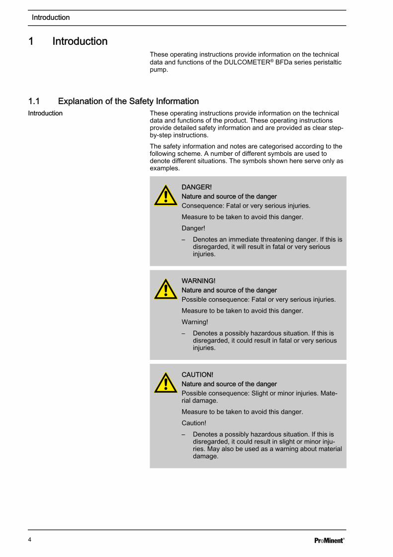
Adjustment gears with integrated frequency converter / 1x 230 VAC
A31 0.37 kW, 9-34 1/min, 12-48 l/h, 8 bar
A32 0.37 kW, 16-60 1/min, 23-86 l/h, 4 bar
A33 0.37 kW, 28-105 1/min, 40-151 l/h, 1 bar
Adjustment gears (external frequency converter required) / 3 x 230 / 400 VAC
A41 0.18 kW, 0-23 1/min, 0-33 l/h, 8 bar
A42 0.18 kW, 0-38 1/min, 0-54 l/h, 8 bar
A43 0.25 kW, 0-60 1/min, 0-86 l/h, 4 bar
A44 0.25 kW, 0-91 1/min, 0-131 l/h, 1 bar
Hose material
0 NR
B NBR
E EPDM
R NR-A
N Norprene (max. 2 bar)
A NBR-A
H Hypalon
Hydraulic connection
A VA BSP 3/8"
B VA NPT 3/8"
C PP BSP 3/8"
D PVDF BSP 3/8"
E PVDF NPT 3/8"
F PVC NPT 3/8"
G Tri-Clamp, VA, 1/2"
H DIN 11851, VA NW10
Base plate
0 Base plate, lacquered steel
1 Base plate, stainless steel
2 Portable unit + lacquered steel base plate
3 Portable unit + stainless steel base plate
Leakage sensor
0 without leakage sensor
L with leakage sensor
Rotor
0 Rotor with 2 rollers
Introduction
7

Identcode
DFBa DULCO®flex DFBa 010
Batch control
0 Without batch control
C With batch control
Special version
0 Standard
H Halar-coated housing
Vacuum system
0 none
Certification
01 CE mark
1.3.2 Identcode DULCO®flex DFBa 013Identcode
DFBa DULCO®flex DFBa 013
Type
013 DFBa 013, 0.039 l/revolution
Drive
000 Pump without drive
Step-down gears / 3 x 230 / 400 VAC
B10 0.12 kW, 15 1/min, 35 l/h, 8 bar
B11 0.12 kW, 20 1/min, 46 l/h, 8 bar
B12 0.18 kW, 29 1/min, 67 l/h, 8 bar
B13 0.18 kW, 46 1/min, 107 l/h, 4 bar
B14 0.25 kW, 57 1/min, 133 l/h, 4 bar
B15 0.25 kW, 70 1/min, 163 l/h, 2 bar
B16 0.25 kW, 85 1/min, 198 l/h, 2 bar
Manual adjustment gears / 3 x 230 / 400 VAC
B21 0.15 kW, 3-16 1/min, 7-37 l/h, 8 bar
B22 0.25 kW, 5-29 1/min, 11-67 l/h, 8 bar
B23 0.25 kW, 10-53 1/min, 23-124 l/h, 4 bar
B24 0.25 kW, 15-80 1/min, 35-187 l/h, 2 bar
Adjustment gears with integrated frequency converter / 1 x 230 VAC
B31 0.37 kW, 9-34 1/min, 21-79 l/h, 8 bar
B32 0.37 kW, 16-60 1/min, 37-140 l/h, 4 bar
B33 0.37 kW, 28-105 1/min, 65-245 l/h, 1 bar
Introduction
8
Identcode
DFBa DULCO®flex DFBa 013
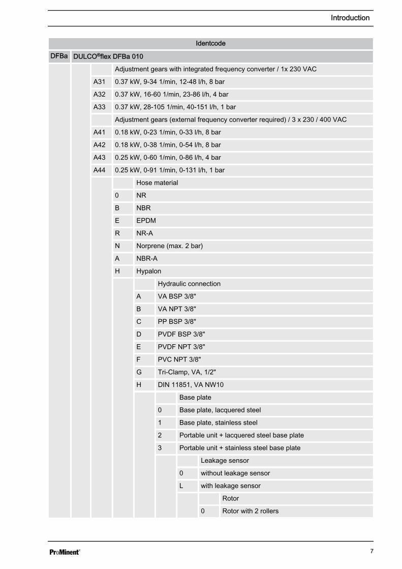
Adjustment gears (external frequency converter required) / 3 x 230 / 400 VAC
B41 0.18 kW, 0-23 1/min, 0-53 l/h, 8 bar
B42 0.18 kW, 0-38 1/min, 0-88 l/h, 8 bar
B43 0.25 kW, 0-60 1/min, 0-140 l/h, 4 bar
B44 0.25 kW, 0-91 1/min, 0-212 l/h, 1 bar
Hose material
0 NR
B NBR
E EPDM
R NR-A
N Norprene (max. 2 bar)
A NBR-A
H Hypalon
Hydraulic connection
A VA BSP 3/8"
B VA NPT 3/8"
C PP BSP 3/8"
D PVDF BSP 3/8"
E PVDF NPT 3/8"
F PVC NPT 3/8"
G Tri-Clamp, VA, 1/2"
H DIN 11851, VA NW15
Base plate
0 Base plate, lacquered steel
1 Base plate, stainless steel
2 Portable unit + lacquered steel base plate
3 Portable unit + stainless steel base plate
Leakage sensor
0 without leakage sensor
L with leakage sensor
Rotor
0 Rotor with 2 rollers
Batch control
0 Without batch control
C With batch control
Special version
Introduction
9

Identcode
DFBa DULCO®flex DFBa 013
0 Standard
H Halar-coated housing
Vacuum system
0 none
Certification
01 CE mark
1.3.3 Identcode DULCO®flex DFBa 016Identcode
DFBa DULCO®flex DFBa 016
Type
016 DFBa 016, 0.092 l/revolution
Drive
000 Pump without drive
Step-down gears / 3 x 230 / 400 VAC
C10 0.18 kW, 14 1/min, 77 l/h, 8 bar
C11 0.18 kW, 20 1/min, 110 l/h, 8 bar
C12 0.25 kW, 32 1/min, 176 l/h, 8 bar
C13 0.25 kW, 46 1/min, 253 l/h, 4 bar
C14 0.37 kW, 57 1/min, 314 l/h, 4 bar
C15 0.37 kW, 70 1/min, 386 l/h, 2 bar
C16 0.37 kW, 85 1/min, 469 l/h, 2 bar
Manual adjustment gears / 3 x 230 / 400 VAC
C21 0.37 kW, 8-50 1/min, 44-276 l/h, 4 bar
C22 0.37 kW, 10-61 1/min, 55-336 l/h, 2 bar
C23 0.37 kW, 16-91 1/min, 88-502 l/h, 1 bar
Adjustment gears with integrated frequency converter / 1 x 230 VAC
C31 0.37 kW, 9-34 1/min, 49-187 l/h, 8 bar
C32 0.37 kW, 16-60 1/min, 88-331 l/h, 2 bar
C33 0.37 kW, 28-105 1/min, 154-579 l/h, 1 bar
Adjustment gears (external frequency converter required) / 3 x 230 / 400 VAC
C41 0.25 kW, 0-23 1/min, 0-126 l/h, 8 bar
C42 0.25 kW, 0-42 1/min, 0-231 l/h, 4 bar
C43 0.37 kW, 0-60 1/min, 0-331 l/h, 2 bar
C44 0.37 kW, 0-91 1/min, 0-502 l/h, 1 bar
Introduction
10

Identcode
DFBa DULCO®flex DFBa 016
Hose material
0 NR
B NBR
E EPDM
R NR-A
N Norprene (max. 2 bar)
A NBR-A
H Hypalon
T TYGON (max. 2 bar)
Hydraulic connection
A VA BSP 3/4"
B VA NPT 3/4"
C PP BSP 3/4"
D PVDF BSP 3/4"
E PVDF NPT 3/4"
F PVC NPT 3/4"
G Tri-Clamp, VA, 1"
H DIN 11851, VA NW 20
Base plate
0 Base plate, lacquered steel
1 Base plate, stainless steel
2 Portable unit + lacquered steel base plate
3 Portable unit + stainless steel base plate
Leakage sensor
0 without leakage sensor
L with leakage sensor
Rotor
0 Rotor with 2 rollers
Batch control
0 Without batch control
C With batch control
Special version
0 Standard
H Halar-coated housing
Vacuum system
0 none
Introduction
11

Identcode
DFBa DULCO®flex DFBa 016
Certification
01 CE mark
1.3.4 Identcode DULCO®flex DFBa 019Identcode
DFBa DULCO®flex DFBa 019
Type
019 DFBa 019, 0.122 l/revolution
Drive
000 Pump without drive
Step-down gears / 3 x 230 / 400 VAC
D10 0.18 kW, 14 1/min, 102 l/h, 2 bar
D11 0.18 kW, 20 1/min, 146 l/h, 2 bar
D12 0.25 kW, 32 1/min, 234 l/h, 2 bar
D13 0.25 kW, 46 1/min, 336 l/h, 2 bar
D14 0.37 kW, 57 1/min, 417 l/h, 2 bar
D15 0.37 kW, 70 1/min, 512 l/h, 2 bar
D16 0.37 kW, 85 1/min, 622 l/h, 2 bar
Manual adjustment gears / 3 x 230 / 400 VAC
D21 0.37 kW, 8-50 1/min, 58-366 l/h, 2 bar
D22 0.37 kW, 10-61 1/min, 73-446 l/h, 2 bar
D23 0.37 kW, 16-91 1/min, 117-666 l/h, 2 bar
Adjustment gears with integrated frequency converter / 1 x 230 VAC
D31 0.37 kW, 9-34 1/min, 65-248 l/h, 8 bar
D32 0.37 kW, 16-60 1/min, 117-439 l/h, 2 bar
D33 0.37 kW, 28-105 1/min, 204-768 l/h, 1 bar
Adjustment gears (external frequency converter required) / 3 x 230 / 400 VAC
D41 0.25 kW, 0-23 1/min, 0-168 l/h, 2 bar
D42 0.25 kW, 0-42 1/min, 0-307 l/h, 2 bar
D43 0.37 kW, 0-60 1/min, 0-439 l/h, 2 bar
D44 0.37 kW, 0-91 1/min, 0-666 l/h, 2 bar
Hose material
0 Norprene (max. 2 bar)
T TYGON (max. 2 bar)
Hydraulic connection
Introduction
12

Identcode
DFBa DULCO®flex DFBa 019
A VA BSP 1"
B VA NPT 1"
C PP BSP 1"
D PVDF BSP 1"
E PVDF NPT 1"
F PVC NPT 1"
G Tri-Clamp, VA, 1"
H DIN 11851, VA NW 25
Base plate
0 Base plate, lacquered steel
1 Base plate, stainless steel
2 Portable unit + lacquered steel base plate
3 Portable unit + stainless steel base plate
Leakage sensor
0 without leakage sensor
L with leakage sensor
Rotor
0 Rotor with 2 rollers
Batch control
0 Without batch control
C With batch control
Special version
0 Standard
H Halar-coated housing
Vacuum system
0 none
Certification
01 CE mark
1.3.5 Identcode DULCO®flex DFBa 022Identcode
DFBa DULCO®flex DFBa 022
Type
022 DFBa 022, 0.248 l/revolution
Drive
Introduction
13

Identcode
DFBa DULCO®flex DFBa 022
000 Pump without drive
Step-down gears / 3 x 230 / 400 VAC
E10 0.25 kW, 17 1/min, 252 l/h, 8 bar
E11 0.37 kW, 23 1/min, 342 l/h, 8 bar
E12 0.55 kW, 38 1/min, 565 l/h, 4 bar
E13 0.55 kW, 45 1/min, 669 l/h, 4 bar
E14 0.55 kW, 54 1/min, 803 l/h, 2 bar
E15 0.75 kW, 66 1/min, 982 l/h, 2 bar
Manual adjustment gears / 3 x 230 / 400 VAC
E21 0.37 kW, 3.9-20.4 1/min, 58-303 l/h, 8 bar
E22 0.55 kW, 6-32 1/min, 89-476 l/h, 4 bar
E23 0.75 kW, 9-48 1/min, 133-714 l/h, 2 bar
Adjustment gears with integrated frequency converter / 1 x 230 VAC
E31 0.55 kW, 11-40 1/min, 163-595 l/h, 4 bar
E32 0.75 kW, 18-63 1/min, 267-937 l/h, 2 bar
E33 1.10 kW, 27-92 1/min, 401-1,368 l/h, 1 bar
Adjustment gears (external frequency converter required) / 3 x 230 / 400 VAC
E41 0.55 kW, 0-29 1/min, 0-431 l/h, 8 bar
E42 0.75 kW, 0-38 1/min, 0-565 l/h, 4 bar
E43 1.10 kW, 0-54 1/min, 0-803 l/h, 2 bar
Hose material
0 NR
B NBR
E EPDM
R NR-A
N Norprene (max. 2 bar)
A NBR-A
H Hypalon
Hydraulic connection
A VA BSP 1"
B VA NPT 1"
C PP BSP 1"
D PVDF BSP 1"
E PVDF NPT 1"
F PVC NPT 1"
G Tri-Clamp, VA, 1"
Introduction
14

Identcode
DFBa DULCO®flex DFBa 022
H DIN 11851, VA NW 25
Base plate
0 Base plate, lacquered steel
1 Base plate, stainless steel
2 Portable unit + lacquered steel base plate
3 Portable unit + stainless steel base plate
Leakage sensor
0 without leakage sensor
L with leakage sensor
Rotor
0 Rotor with 2 rollers
Batch control
0 Without batch control
C With batch control
Special version
0 Standard
H Halar-coated housing
Vacuum system
0 none
Certification
01 CE mark
Introduction
15
2 Safety and responsibility2.1 General safety information
WARNING!Live partsPossible consequence: Fatal or very serious injuries– Measure: The device must be disconnected from
the power supply before it is opened– Isolate damaged, faulty or manipulated devices
from the mains in order to de-energise.
WARNING!Emergency stop switchPossible consequence: Fatal or very serious injuriesAn emergency stop switch is to be connected for theentire plant. This should enable the entire plant to beshut down in the event on an emergency in such a waythat the overall plant can be brought into a safe condi‐tion.
WARNING!Unauthorised accessPossible consequence: Fatal or very serious injuries– Measure: Ensure that there can be no unauthor‐
ised access to the unit
WARNING!Hazardous media / contamination of persons andequipmentPossible consequence: Fatal or very serious injuries.material damage– Ensure that the pump hoses are resistance against
the media being conveyed– Always observe the the safety data sheets for the
media to be conveyed. The system operator mustensure that these safety data sheets are availableand that they are kept up-to-date
– The safety data sheets for the media beingconveyed are always decisive for initiating countermeasures in the event of leakage to the mediabeing conveyed
– Observe the general restrictions in relation toviscosity limits, chemical resistance and density
– Always switch the pump off before exchanging thepump hose
Safety and responsibility
16

WARNING!Correct and proper usePossible consequence: Fatal or very serious injuries– The unit is not intended to convey or regulate
gaseous or solid media– Do not exceed the rated pressure, speed or
temperature for the pump– The unit may only be used in accordance with the
technical data and specifications provided in theseoperating instructions and in the operating instruc‐tions for the individual components
– The system is not designed for use in areas at riskfrom explosion
– Only switch the pump on if it has been properlyfastened to the floor
– Only switch the pump on if it the front cover hasbeen attached.
WARNING!Operational lifetime of the pump hosesPossible consequence: Fatal or very serious injuriesThe operational lifetime of the pump hoses cannot beprecisely specified. For this reason, the possibility offracture and consequential leakage of liquids must beaccounted for. If the hose rupture alarm (optional) isfitted, then the pump can be stopped and / or an elec‐trical valve can be actuated.In addition, you must avoid particles from untighthoses being introduced into the media beingconveyeed. This can be achieved e.g. by means offiltration, a hose rupture alarm or other means suitablefor the respective process.
CAUTION!CIP cleaningIn the event of CIP cleaning, it is necessary to obtaininformation from the manufacturer about correct instal‐lation of the pump (a special installation is required),as well as regarding the compatibility of the cleaningagents with the pump hoses of the pump and the otherhydraulic connections.Cleaning should be undertaken at the recommendedmaximum temperature.
CAUTION!Direction of rotation / flow directionPossible consequence: Material damage right throughto destruction of the unit– The pump's direction of rotation in relation to the
desired flow direction must be checked prior toevery start.
Safety and responsibility
17
CAUTION!Environmental influencesPossible consequence: Material damage right throughto destruction of the unit– The device is not suitable for outdoor operation– Take suitable measures to protect the device from
environmental influences such as:– UV rays– Moisture– Frost, etc.
Safety and responsibility
18

3 Functional descriptionThe package contents supplied with the DULCO®flex DFBa isselectable via the identcode.
The DULCO®flex DFBa is a displacement pump. The feed chem‐ical is conveyed by the rotor squeezing the hose in the direction offlow. No valves are needed for this. This ensures gentle handlingof the metered media.
The DULCO®flex DFBa has been designed for safe and uncompli‐cated operation, as well as straightforward maintenance.
The DULCO®flex DFBa can be used for many different media.However, this pump type is often the optimal solution for abrasive,shear-sensitive and viscose media.Typical areas of use include processes where only a low dischargepressure is required (max. 8 bar).
3.1 ConstructionMain modules:n Drive Unitn Housingn Base frameThe pump housing is closed off with a screwed front cover in orderto avoid the risk of injury.The motor serves to drive the rotor. Two rollers at the ends of therotor serve to press the pump hose against the pump housing.The rotary movement of the rotors alternately press and relax therollers in relation to the pump hose. This serves to suck the mediain and convey it into the metering line.
Brief functional description
Functional description
19

3.2 Overview of the Device
P_DX_0017_SW
Fig. 1: Diagram of functional principle1 Housing2 Rotor
3 Rollers4 Hose
Functional description
20

4 Transport, storage, assembly and Installationn User qualification, transport and storage: instructed persons,
see Ä Chapter 1.2 “Users' qualifications” on page 5n User qualification, assembly: trained qualified personnel, seeÄ Chapter 1.2 “Users' qualifications” on page 5
n User qualification, electrical installation: Qualified electrician,see Ä Chapter 1.2 “Users' qualifications” on page 5
WARNING!Safety data sheetPossible consequence: Fatal or very serious injuriesAlways observe the corresponding data sheets for themedia when carrying out any tasks which involvecontact with the media that is to be conveyed.
4.1 TransportTransportn The pump is protected by means of cardboard packagingn The packaging materials can be recycledn For environmental conditions for storage and transportation
see Ä Chapter 4.3.1 “Ambient conditions” on page 22
4.2 StorageStoragen The pump hose should be removed from the housing during
the duration of storagen For storage durations longer than 60 days, the coupling
surfaces (terminals, reducing adaptors, motors) are to beprotected with suitable antioxidant agents
n For environmental conditions for storage and transportationsee Ä Chapter 4.3.1 “Ambient conditions” on page 22
4.3 Assembly
CAUTION!Possible consequence: Slight or minor injuries, mate‐rial damage.Carry out the assembly work before the electricalinstallation is undertaken!Observe the permissible environmental conditions!
Transport, storage, assembly and Installation
21

4.3.1 Ambient conditions
NOTICE!Ambient conditionsPossible consequence: Property damage andincreased wear and tearAssembly is to be carried out in the following order. Ifthe must has to be installed outdoors, then it is to beequipped with protection against sunlight and weatherinfluences.When positioning the pump, ensure that sufficientroom for access is provided for all types of mainte‐nance work.
There are limit values for temperature and pressure, depending onthe type of hose selected. These limit values are described in thefollowing section:
Limit values for hose temperature and pressure
MaterialHose
min. temp. (°C)Feed chemical
max. temp. (°C)Feed chemical
min. temp. (°C)Environment
max. pressure (bar)
NR -20 80 -40 8
NBR -10 80 -40 8
EPDM -10 80 -40 8
NR-A -10 80 -40 8
NBR-A -10 80 -40 8
NORPREN -40 120 -40 2
TYGON -10 70 -40 2
Also observe the general safety information, see Ä Chapter 2.1 “General safety information” on page 16
4.3.2 Alignment of the suction sideThe pump is to be positioned as near as possible to the liquidcontainer, so that the suction side is kept as short and straight aspossible.The suction line must be absolutely airtight and made of a suitablematerial, so that it is not squeezed together under vacuum.The diameter must correspond to the rated diameter of the pumphose. A larger diameter is recommended in the event of viscoseliquids.The pump is self-priming and does not require an admission valve.The pump is reversible and the suction connection can thereforecomprise of one of two options. Normally the option is selectedwhich is best suited to the physical conditions of the installation.It is recommended to use a flexible transition between two fixedpipes and the hydraulic connection of the pump, in order to avoidthe transmission of vibrations.
Transport, storage, assembly and Installation
22

4.3.3 Alignment of the discharge sideThe discharge line is to be kept as straight and short as possible,in order to avoid performance reduction.The diameter must correspond to the rated diameter of the pumphose. A larger diameter is recommended in the event of viscoseliquids.It is recommended to use a flexible transition between two fixedpipes and the hydraulic connection of the pump, in order to avoidthe transmission of vibrations.
4.3.4 Adjusting the roller pressureThe peristaltic pump is equipped with spacer plates (6), in order toadjust the precise pressure distance to the roller (9) (dependent onspeed and operating pressure).
P_DX_0013_SW
Fig. 2: Space plates / roller6 Spacer plates9 Roller
Transport, storage, assembly and Installation
23

1
234 P_DX_0021_SW
Fig. 3: Squeezing the hose1 Hose in normal shape2 Excessive squeezing (increased wear and tear
to pump and hose)
3 Perfect squeezing4 Insufficient squeezing (backflowing media in the
cavity will destroy the hose within a short periodof time)
The spacer plates are fitted in the factory. You can adapt thenumber of spacer plates to the actual operating conditionsaccording to the following table.DFBa 010 / Number of spacer plates of 0.5 mm thickness (exceptNorpren and TYGON):
1/min 0-19 20-39 40-59 60-79 80-99
bar
0,5 1 1 1 1 1
2,0 1 1 1 1 1
4,0 * 2 1 1 1 1
6,0 2 2 2
8,0 3 2
* Supplied state
DFBa 010 / Number of spacer plates of 0.5 mm thickness (Norprenand TYGON):
1/min 0-19 20-39 40-59 60-79 80-99
bar
0,5 5 5 5 5 5
2,0 * 5 5 5 5 5
* Supplied state
DFBa 013 / Number of spacer plates of 0.5 mm thickness (exceptNorpren and TYGON):
1/min 0-19 20-39 40-59 60-79 80-99
bar
0,5 1 1 1 1 1
2,0 1 1 1 1 1
* Supplied state
Transport, storage, assembly and Installation
24

1/min 0-19 20-39 40-59 60-79 80-99
bar
4,0 * 2 1 1 1 1
6,0 2 2 2
8,0 3 2
* Supplied state
DFBa 013 / Number of spacer plates of 0.5 mm thickness (Norprenand TYGON):
1/min 0-19 20-39 40-59 60-79 80-99
bar
0,5 5 5 5 5 5
2,0* 5 5 5 5 5
* Supplied state
DFBa 016 / Number of spacer plates of 0.5 mm thickness (exceptNorpren and TYGON):
1/min 0-19 20-39 40-59 60-79 80-99
bar
0,5 1 1 1 1 1
2,0 1 1 1 1 1
4,0 * 2 1 1 1 1
6,0 2 2 2
8,0 3 3
* Supplied state
DFBa 016 / Number of spacer plates of 0.5 mm thickness (Norprenand TYGON):
1/min 0-19 20-39 40-59 60-79 80-99
bar
0,5 9 9 9 9 9
2,0 * 9 9 9 9 9
* Supplied state
DFBa 019 / Number of spacer plates of 0.5 mm thickness (Norprenand TYGON):
1/min 0-19 20-39 40-59 60-79 80-99
bar
0,5 5 5 5 5 5
2,0 * 5 5 5 5 5
* Supplied state
Transport, storage, assembly and Installation
25

DFBa 022 / Number of spacer plates of 0.5 mm thickness:
1/min 0-19 20-39 40-59 60-79 80-99
bar
0,5 2 2 1 1 1
2,0 2 2 2 2 2
4,0 * 3 3 2 2 2
6,0 3 3 3
8,0 4 3
* Supplied state
4.3.5 Performance curves
NOTICE!Maximum pressure under continuous operationThe dotted line indicates the limit for maximum pres‐sure under continuous operation
1/min
l /h
8 bar 4 bar 2 bar
200
180
160
140
120
100
80
60
40
20
010 20 30 40 50 60 70 80 90 100 110 120 130 140
P_DX_0022_SW
Fig. 4: DFBa 10
Transport, storage, assembly and Installation
26

1/min
l /h
8 bar 4 bar 2 bar
330
300
270
240
210
180
150
120
90
60
30
0 10 20 30 40 50 60 70 80 90 100 110 120 130 140
P_DX_0023_SW
Fig. 5: DFBa 013
0
80
160
240
320
400
480
560
640
720
800
0 10 20 30 40 50 60 70 80 90 100 110 120 130 140
1/min
l /h
8 bar 4 bar 2 barP_DX_0015_SW
Fig. 6: DFBa 016
Transport, storage, assembly and Installation
27

0
104
208
312
416
520
624
728
832
936
1040
0 10 20 30 40 50 60 70 80 90 100 110 120 130 140
1/min
l /h
P_DX_0016_SW
Fig. 7: DFBa 019
1/min
l /h
100
8 bar 4 bar 2 bar
10 20 30 40 50 60 70 80 90
1500
1350
1200
1050
900
750
600
450
300
150
0
P_DX_0024_SW
Fig. 8: DFBa 022
Transport, storage, assembly and Installation
28

5 Commissioningn User qualification, commissioning: trained user, see Ä Chapter
1.2 “Users' qualifications” on page 5
5.1 Testing prior to commissioning the pumpThe following tests are to be carried out:n Ensure that the pump has not been damaged during transpor‐
tation or storage. Immediately report any damage to thesupplier
n Check that the mains voltage is suitable for the motorn Ensure that the hose is suitable for the fluid to be conveyed
and that it is not damagedn Make sure that the temperature of the liquid does not exceed
the recommended temperature rangen Only switch the pump on if it the front cover has been properly
attachedn Check that the rollers are correctly fitted and fastenedn Check that the hose and rollers are sufficiently lubricatedn Check that the thermal overload protection (not included in the
delivery scope) corresponds to the value specified on themotor type plate
n Check whether the direction of rotation is correctly adjustedn Check that the optional electrical components are connected
and are working properlyn Install a manometer in the pressure line if the back-pressure
value is unknownn Check the operating instructions in order to ensure that the
flow values, pressures and power consumption of the motor donot exceed the rated values
n Install a pressure relief valve in the pressure line in order toprotect the pump in the event that a valve is unintentionallyclosed off or the line is blocked in another way.
Commissioning
29

6 Operating the DFBan User qualification, operation: instructed persons, seeÄ Chapter 1.2 “Users' qualifications” on page 5
The peristaltic pump is to be fully integrated into the customer'sdesignated plant and is then controlled by this plant. It is notpossible to operate the pump directly.
Operating the DFBa
30

7 Maintenance, repair, malfunctions, disposal and spare partsn User qualification, maintenance and disposal: instructed
persons, see Ä Chapter 1.2 “Users' qualifications” on page 5n User qualification, repair and malfunctions: trained user, seeÄ Chapter 1.2 “Users' qualifications” on page 5
7.1 Maintenance
CAUTION!Disconnect the pump from the mainsPossible consequence: Personal injuryYou may only carry out work on the pump after it haspreviously been switched off and disconnected fromthe mains.
Lubricationn Check that the rollers and the hose are sufficiently lubricated
– Check every 200 operating hoursn Check whether the oil level is correct for the step-down gears
– Exchange the oil at regular intervals in accordance with thestep-down gear maintenance manual.
7.2 Exchanging the pump hoses1. Close off all valves, in order to prevent leakage of the feed
chemical2. Dismantle the pump hoses from both discharge and suction
sides3. Remove the front cover4. Remove a roller incl. the spacer plate (the roller that is not
touching the pump hose)5. Turn the rotor with the help of the motor so that the remaining
roller is not pressing against the pump hose6. Remove the pressure flange from the pump housing7. Remove the pump hose to be exchanged8. Dismantle the hydraulic connections from both pump hose
ends
1. Clean the interior surfaces of the pump housing2. Lubricate the internal surfaces of the pump housing at the
contact surfaces to the pump hose3. Check the rollers. Ensure that the roller surfaces are not
damaged4. Attach the hydraulic connections at both hose ends with the
help of the pressure flange5. Lay the pump hose into the pump housing6. Lubricate the pump hose and the rollers7. Fasten the pressure flange to the pump casing
Exchanging the pump hoses -dismantling
Exchanging the pump hoses - installa‐tion
Maintenance, repair, malfunctions, disposal and spare parts
31

8. Turn the rotor with the help of the motor so that the remainingroller presses against the pump hose
9. Re-attach the second roller with spacer plates back onto therotor
10. Attach the front cover to the pump housing11. Mount the pump hoses from both discharge and suction
sides12. Open all of the valves
7.3 TroubleshootingProblem Possible cause Solution
Increased pump temperature Pump hose has no lubricant Lubricate pump hose
Increased product temperature Reduce product temperature
Insufficient or poor suction condi‐tions
Check suction line for blockages
Pump speed too high Reduce pump speed
Reduced flow or pressure Valves on discharge and orsuction side completely or partiallyclosed
Open valves
Pump hose insufficientlycompressed
Check roller fastening
Pump hose rupture (the productleaks out into the housing)
Exchange pump hose
Partial blockage of the suction line Clean pipe
Insufficient product quantity instorage container
Fill storage container or exchangepump
Insufficient diameter on thesuction side
Increase the diameter on thesuctions side, as far as possible
Suction line too long Shorten the suction line, as far aspossible
High viscosity of medium Reduce viscosity, as far aspossible
Air introduction in the suctionconnections
Check connections and accesso‐ries for air tightness
Vibrations on pumps and pipelines The pipes are not correctlyfastened
Fasten pipes correctly (e.g. wallbrackets)
Pump speed too high Reduce pump speed
Insufficient nominal width of thepipes
Increase nominal width
Pump base plate loose Fasten base plate
Pulsation dampers insufficient ormissing
Install pulsation dampers onsuction and / or discharge side.
Short operational lifetime of thehoses
Chemical exposure Check the compatibility of thehose with the liquid beingconveyed, the cleaning fluid andthe lubricant
Maintenance, repair, malfunctions, disposal and spare parts
32

Problem Possible cause Solution
High pump speed Reduce pump speed
High conveying temperature Reduce product temperature
High operating pressure Reduce operating pressure
Pump cavitations Check the suction conditions
Pump hose pulled into the pumphousing
High inlet pressure (> 3 bar) Reduce inlet pressure
Pump hose filled with deposits Clean or replace the pump hose
Holder (pressure flange) insuffi‐ciently tightened
Re-tighten holder (pressureflange)
The pump does not start up Insufficient motor performance Check motor and replace if neces‐sary
Insufficient output from frequencyconverter
The frequency converter mustmatch the motor
Check voltage. Start occurs atminimum 10 Hz
Blockage in the pump Check if the suction or dischargeside is blocked. Rectify blockage
Maintenance, repair, malfunctions, disposal and spare parts
33
7.4 Disposal of Used Parts
WARNING!Danger due to feed chemicalsPossible consequence: Fatal or serious injuriesIn the event that damage to the pump hose causes thepump to be contaminated with feed chemicals, then itis to be decontaminated with suitable agents (refer tothe feed chemical safety data sheets).
NOTICE!If no Declaration of Decontamination is affixed to thedelivery, acceptance of the devices will be refused.(also available as download from: www.promi‐nent.com)A signed "Declaration of Decontamination" is requiredby law and in order to protect our staff, before youorder can be processed.Please ensure that this is attached to the outside of thepackage. Otherwise we are unable to accept yourdelivery.
NOTICE!Regulations governing disposal of used parts– Note the current national regulations and legal
standards which apply in your country
The pump hose is to be removed and disposed of on-site beforesending the pump to ProMinent Dosiertechnik GmbH, Heidelberg /Germany.ProMinent Dosiertechnik, Heidelberg/Germany is prepared to takeback clean used parts.
7.5 Spare parts
Maintenance, repair, malfunctions, disposal and spare parts
34

P_DX_0018_SW
Fig. 9: Spare parts exploded view DFBa 010/013
DFBa 010refer to Fig. 9
Pos. Description Quantity Reference Part number
1 Pump housing 1 102.02.01
2 Rotor (2 rollers) 1 102.02.03
3 Rotor shaft 2 102.01.04
4 Roller ball bearings 4 102.01.02
5 Roller ⌀35 2 102.01.09
6 Long bolts 1 102.00.07
Short bolts 3 102.00.14
7 Front cover 1 102.00.08
8 Seal front cover 1 102.00.05
9 Connection VA-BSP 2 102.00.10
Connection PP-BSP 2 102.00.15
Connection PVDF-BSP 2 102.00.16
Connection VA-NPT 2 102.00.17
Maintenance, repair, malfunctions, disposal and spare parts
35

DFBa 010refer to Fig. 9
Pos. Description Quantity Reference Part number
Connection PP-NPT 2 102.00.18
Connection PVDF-NPT 2 102.00.19
Connection DIN 2 102.00.20
Connection SMS 2 102.00.21
Connection TRI-CLAMP 2 102.00.22
10 Pressure flange, standard 2 102.00.11
Pressure flange, thermoplastic hose 2 102.00.23
11 Base plate 1 102.00.12
Base plate, stainless steel 1 102.00.24
12 Nut 1 102.00.25
13 Box nut 3 102.00.26
14 Pump hose NR 1 1037150
Pump hose NBR 1 1037151
Pump hose EPDM 1 1037152
Pump hose NR-A 1 1037153
Pump hose NBR-A 1 1037154
Pump hose NORPRENE 1 1037155
Pump hose HYPAGLON 1 1037156
15 Drive 1
16 Roller holder 2 102.01.06
17 Spacer plate 102.01.07
18 Rotor washer 1 102.01.10
DFBa 013refer to Fig. 9
Pos. Description Quantity Reference Part number
1 Pump housing 1 102.01.01
2 Rotor (2 rollers) 1 102.01.03
3 Rotor shaft 2 102.01.04
4 Roller ball bearings 4 102.01.02
5 Roller ⌀35 2 102.01.09
6 Long bolts 1 102.00.07
Short bolts 3 102.00.14
7 Front cover 1 102.01.08
8 Seal front cover 1 102.01.05
Maintenance, repair, malfunctions, disposal and spare parts
36

DFBa 013refer to Fig. 9
Pos. Description Quantity Reference Part number
9 Connection VA-BSP 2 103.00.10
Connection PP-BSP 2 103.00.15
Connection PVDF-BSP 2 103.00.16
Connection VA-NPT 2 103.00.17
Connection PP-NPT 2 103.00.18
Connection PVDF-NPT 2 103.00.19
Connection DIN 2 103.00.20
Connection SMS 2 103.00.21
Connection TRI-CLAMP 3/4" 2 103.00.22
10 Pressure flange, standard 2 103.00.11
Pressure flange, thermoplastic hose 2 102.00.11
11 Base plate 1 102.00.12
Base plate, stainless steel 1 102.00.24
12 Nut 1 102.00.25
13 Box nut 3 102.00.26
14 Pump hose NR 1 1037157
Pump hose NBR 1 1037158
Pump hose EPDM 1 1037159
Pump hose NR-A 1 1037160
Pump hose NBR-A 1 1037161
Pump hose NORPRENE 1 1037162
Pump hose HYPALON 1 1037163
15 Drive 1
16 Roller holder 2 102.01.06
17 Spacer plate 102.01.07
18 Rotor washer 1 102.01.10
Maintenance, repair, malfunctions, disposal and spare parts
37

P_DX_0014_SW
Fig. 10: Spare parts exploded view DFBa 016/019
DFBa 16refer to Fig. 10
Pos. Description Quantity Reference Part number
1 Pump housing 1 101.02.01
2 Rotor 1 101.02.03
3 Rotor shaft 2 101.01.04
4 Roller ball bearings 4 101.01.36
5 Roller ⌀45 2 105.01.07
6 Long bolts 1 102.00.07
Short bolts 3 102.00.14
7 Front cover 1 101.00.12
8 Seal front cover 1 101.00.11
9 Connection VA-BSP 2 101.00.13
Connection PP-BSP 2 101.00.14
Connection PVDF-BSP 2 101.00.15
Maintenance, repair, malfunctions, disposal and spare parts
38

DFBa 16refer to Fig. 10
Pos. Description Quantity Reference Part number
Connection VA-NPT 2 101.00.16
Connection PP-NPT 2 101.00.17
Connection PVDF-NPT 2 101.00.18
Connection DIN 2 101.00.19
Connection SMS 2 101.00.20
Connection TRI-CLAMP 2 101.00.21
10 Pressure flange, standard 2 101.00.22
Pressure flange, thermoplastic hose 2 101.00.23
11 Base plate 1 101.00.24
Base plate, stainless steel 1 101.00.25
12 Nut 1 102.00.25
13 Box nut 3 102.00.26
14 Pump hose NR 1 1037164
Pump hose NBR 1 1037165
Pump hose EPDM 1 1037166
Pump hose NR-A 1 1037167
Pump hose NBR-A 1 1037168
Pump hose NORPREN 1 1037169
Pump hose TYGON 1 1037170
Pump hose HYPAGLON 1 1037171
15 Drive 1
16 Roller holder 2 101.02.34
17 Spacer plate 101.02.35
18 Rotor washer 1 101.02.13
19 Cover seal 1 101.02.40
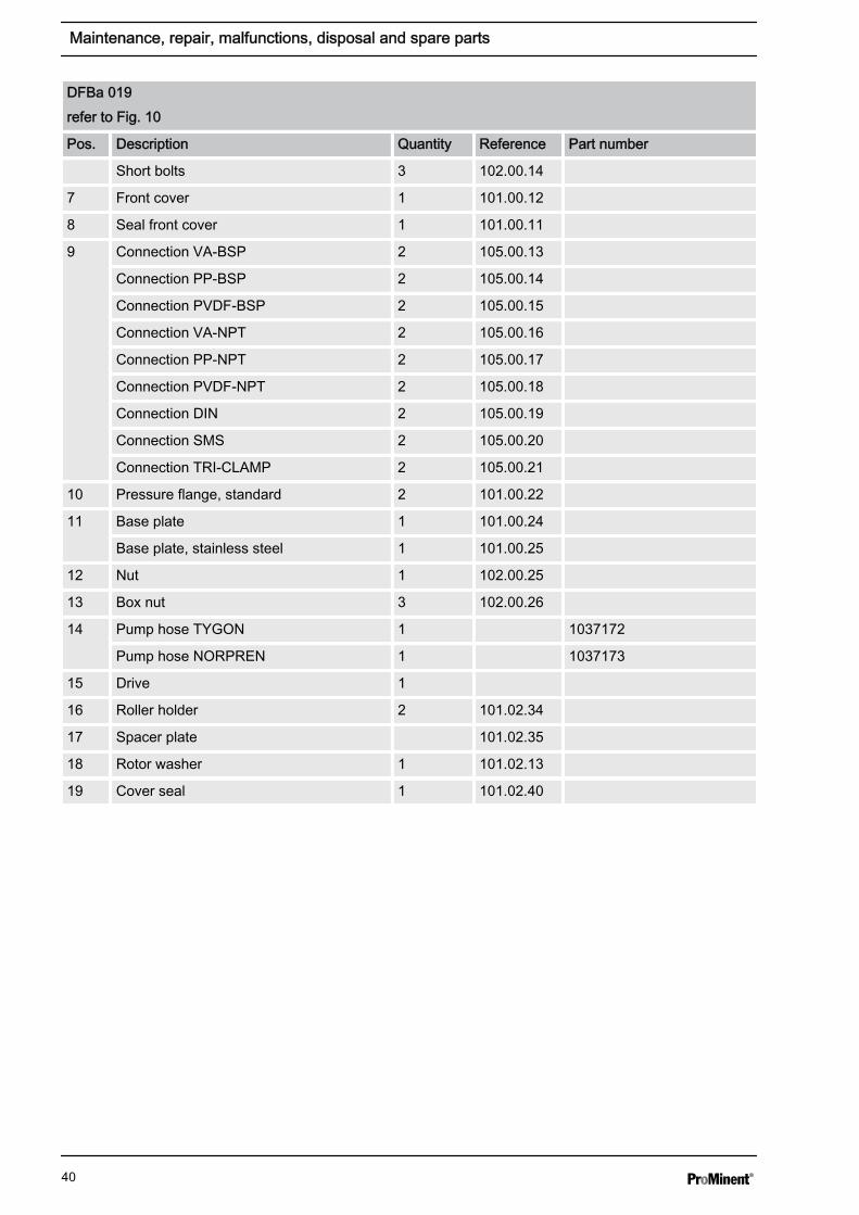
DFBa 019refer to Fig. 10
Pos. Description Quantity Reference Part number
1 Pump housing 1 101.02.01
2 Rotor 1 101.02.03
3 Rotor shaft 2 101.01.04
4 Roller ball bearings 4 101.01.36
5 Roller D45 2 105.01.07
6 Long bolts 1 102.00.07
Maintenance, repair, malfunctions, disposal and spare parts
39
DFBa 019refer to Fig. 10
Pos. Description Quantity Reference Part number
Short bolts 3 102.00.14
7 Front cover 1 101.00.12
8 Seal front cover 1 101.00.11
9 Connection VA-BSP 2 105.00.13
Connection PP-BSP 2 105.00.14
Connection PVDF-BSP 2 105.00.15
Connection VA-NPT 2 105.00.16
Connection PP-NPT 2 105.00.17
Connection PVDF-NPT 2 105.00.18
Connection DIN 2 105.00.19
Connection SMS 2 105.00.20
Connection TRI-CLAMP 2 105.00.21
10 Pressure flange, standard 2 101.00.22
11 Base plate 1 101.00.24
Base plate, stainless steel 1 101.00.25
12 Nut 1 102.00.25
13 Box nut 3 102.00.26
14 Pump hose TYGON 1 1037172
Pump hose NORPREN 1 1037173
15 Drive 1
16 Roller holder 2 101.02.34
17 Spacer plate 101.02.35
18 Rotor washer 1 101.02.13
19 Cover seal 1 101.02.40
Maintenance, repair, malfunctions, disposal and spare parts
40
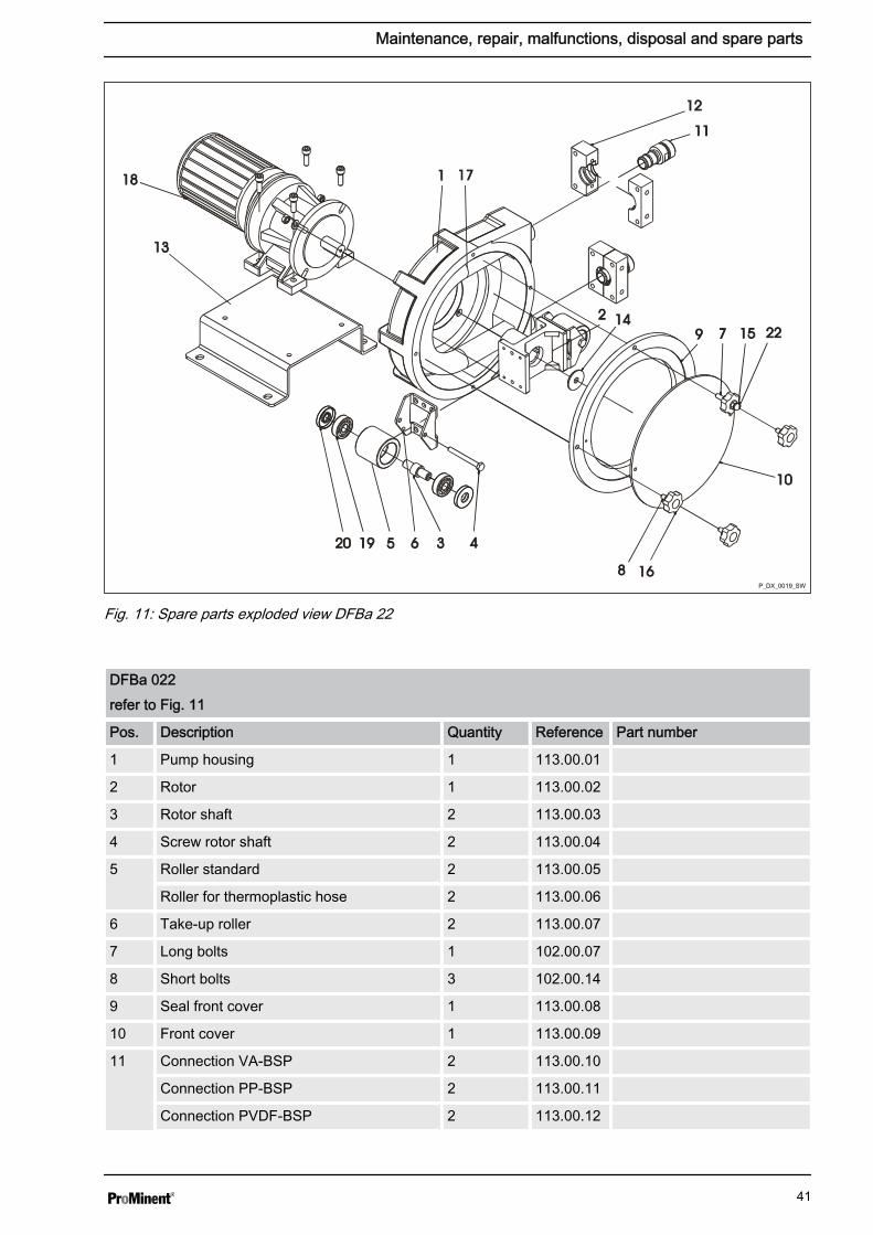
P_DX_0019_SW
Fig. 11: Spare parts exploded view DFBa 22
DFBa 022refer to Fig. 11
Pos. Description Quantity Reference Part number
1 Pump housing 1 113.00.01
2 Rotor 1 113.00.02
3 Rotor shaft 2 113.00.03
4 Screw rotor shaft 2 113.00.04
5 Roller standard 2 113.00.05
Roller for thermoplastic hose 2 113.00.06
6 Take-up roller 2 113.00.07
7 Long bolts 1 102.00.07
8 Short bolts 3 102.00.14
9 Seal front cover 1 113.00.08
10 Front cover 1 113.00.09
11 Connection VA-BSP 2 113.00.10
Connection PP-BSP 2 113.00.11
Connection PVDF-BSP 2 113.00.12
Maintenance, repair, malfunctions, disposal and spare parts
41

DFBa 022refer to Fig. 11
Pos. Description Quantity Reference Part number
Connection VA-NPT 2 113.00.13
Connection PP-NPT 2 113.00.14
Connection PVDF-NPT 2 113.00.15
Connection DIN 2 113.00.16
Connection SMS 2 113.00.17
Connection TRI-CLAMP 2 113.00.18
12 Pressure flange, standard 2 113.00.19
Pressure flange, thermoplastic hose 2 113.00.20
13 Base plate 1 113.00.21
Base plate, stainless steel 1 113.00.22
14 Rotor washer 1 113.00.23
15 Nut 1 102.00.25
16 Box nut 3 102.00.26
17 Pump hose NR 1 1037175
Pump hose NBR 1 1037176
Pump hose EPDM 1 1037178
Pump hose NR-A 1 1037179
Pump hose NBR-A 1 1037180
Pump hose NORPREN 1 1037181
Pump hose HYPALON 1 1037182
18 Drive 1
19 Roller bearing 4 113.00.31
20 Seal roller bearing 4 113.00.32
Lubricant
Pos. Description Quantity Reference Part number
1 0.5 kg silicone grease for DULCO®flex DFBa 1 1037255
2 1.0 kg silicone grease for DULCO®flex DFBa 1 1037256
Maintenance, repair, malfunctions, disposal and spare parts
42

8 Technical data DFBaTypeDFBa
Feed ratein l/U
P max.in bar
Flow rateat max.pressurein l/h
Rollers/shoes
Hoseinterior⌀ in mm
Solidsmax.⌀ in mm
Weightwithoutdrivein kg
ConnectorDN
010 0,024 8 56 Rollers 10 2,5 6 3/8"
013 0,039 8 92 Rollers 13 3,3 6 3/8"
016 0,092 8 200 Rollers 16 4,0 13 3/4"
019 0,12 2 600 Rollers 19 4,8 13 1"
022 0,24 8 375 Rollers 22 5,5 22 1"
8.1 Dimensions DFBa 010 / 013
L
J
I
K
H
AB
C
D
FG
E P_DX_0025_SW
Fig. 12: Dimensions DFBa 010 / 013A 70 mmB *C *D 190 mmE 30 mmF 160 mmG 30 mm
H 61 mmI 60 mmJ 115 mmK 210 mmL 3/8" BSP* Dependent on selected drive
Technical data DFBa
43

8.2 Dimensions DFBa 016 / 019
F
J
I
K
H
L
G
E
A
B
C
D
P_DX_0026_SW
Fig. 13: Dimensions DFBa 016 / 019A 119 mmB *C *D 190 mmE 30 mmF 160 mmG 30 mm
H 75 mmI 60 mmJ 170 mmK 265 mmL 3/4" BSP* Dependent on selected drive
Technical data DFBa
44

8.3 Dimensions DFBa 022
L
J
IH
K
A
B
C
F
G
E
D
P_DX_0027_SW
Fig. 14: Dimensions DFBa 022A 110 mmB *C *D 245 mmE 25 mmF 175 mmG 25 mm
H 95 mmI 85 mmJ 210 mmK 355 mmL 1" BSP* Dependent on selected drive
Technical data DFBa
45

9 DFBa technical appendices9.1 Declaration of Conformity
Fig. 15: EC Declaration of Conformity
DFBa technical appendices
46

10 IndexBBackflowing media............................................... 24CCorrect and proper use........................................ 17Counter measures................................................ 17DDisplacement pump............................................. 19Disposal............................................................... 34EEmergency stop switch........................................ 16FFunctional principle.............................................. 20LLive parts.............................................................. 16
RRollers.................................................................. 24SSafety data sheet................................................. 17Safety information................................................ 16Safety Information.................................................. 4Spacer plates....................................................... 24Squeezing the hose............................................. 24UUnauthorised access............................................ 16Users' qualifications............................................... 5
Index
47