Embed Size (px)
Citation preview

O P E R AT I N G I N S T R U C T I O N S
FiberizerF2-T.S
Serial No.: 22978 Equip. No.: PD-QS-3005A
Codeword: Aylesford - East

Date: 2000-12-05

Fiberizer
Copyright
Copyright by VOITH SULZER Stoffaufbereitung GmbH & Co. KG. All rights reserved. No part ofthis publication may be reproduced, stored in a retrieval system, or transmitted in any form or byany means, graphic, electronic, mechanical, photocopying, recording, taping, or otherwise with-out the prior permission of the copyright owner.
Manufacturer’s name and address
VOITH SULZER Stoffaufbereitung GmbH & Co. KG
Postfach 2120
D-88191 Ravensburg
Telephone: (0751) 8301
Telefax: (0751) 832280
Telex: 732901
F2-T-GB


Fiberizer
Table of Contents
1 Introduction . . . . . . . . . . . . . . . . . . . . . . . . . . . . . . . . . . 1-1
1.1 Explanation of warnings and symbols . . . . . . . . . . . . . . . 1-11.2 Numbering of pages, figures and tables . . . . . . . . . . . . . 1-21.3 Abbreviations . . . . . . . . . . . . . . . . . . . . . . . . . . . . . . . . . . 1-31.4 Dimensions . . . . . . . . . . . . . . . . . . . . . . . . . . . . . . . . . . . 1-3
2 Safety Instructions . . . . . . . . . . . . . . . . . . . . . . . . . . . . . 2-1
2.1 General safety instructions . . . . . . . . . . . . . . . . . . . . . . . . 2-12.2 Designated use of the machine . . . . . . . . . . . . . . . . . . . . 2-22.3 Organizational measures . . . . . . . . . . . . . . . . . . . . . . . . . 2-22.4 Selection and qualification of personnel . . . . . . . . . . . . . . 2-52.5 Noise protection . . . . . . . . . . . . . . . . . . . . . . . . . . . . . . . . 2-52.6 Additional hazards . . . . . . . . . . . . . . . . . . . . . . . . . . . . . . 2-6
3 Technical Data . . . . . . . . . . . . . . . . . . . . . . . . . . . . . . . . 3-1
3.1 Machine data . . . . . . . . . . . . . . . . . . . . . . . . . . . . . . . . . . 3-13.2 Screen plate . . . . . . . . . . . . . . . . . . . . . . . . . . . . . . . . . . . 3-13.3 Weights . . . . . . . . . . . . . . . . . . . . . . . . . . . . . . . . . . . . . . 3-13.4 Operating data . . . . . . . . . . . . . . . . . . . . . . . . . . . . . . . . . 3-23.5 Drive data . . . . . . . . . . . . . . . . . . . . . . . . . . . . . . . . . . . . . 3-2
4 Technical Description . . . . . . . . . . . . . . . . . . . . . . . . . . 4-1
4.1 Use . . . . . . . . . . . . . . . . . . . . . . . . . . . . . . . . . . . . . . . . . . 4-14.2 Principle of operation . . . . . . . . . . . . . . . . . . . . . . . . . . . . 4-24.3 Design . . . . . . . . . . . . . . . . . . . . . . . . . . . . . . . . . . . . . . . 4-4
5 Installation . . . . . . . . . . . . . . . . . . . . . . . . . . . . . . . . . . . 5-1
5.1 Unpacking the machine . . . . . . . . . . . . . . . . . . . . . . . . . . 5-15.2 Transporting the machine . . . . . . . . . . . . . . . . . . . . . . . . 5-15.3 Disposing of packing materials . . . . . . . . . . . . . . . . . . . . 5-15.4 Laying the foundations . . . . . . . . . . . . . . . . . . . . . . . . . . . 5-25.5 Setting up and aligning . . . . . . . . . . . . . . . . . . . . . . . . . . . 5-45.6 Connecting . . . . . . . . . . . . . . . . . . . . . . . . . . . . . . . . . . . . 5-75.7 Checking the direction of rotation . . . . . . . . . . . . . . . . . . 5-115.8 Mounting and dismounting the belt pulleys . . . . . . . . . . 5-125.9 Mounting the belts . . . . . . . . . . . . . . . . . . . . . . . . . . . . . 5-145.10 Preparing for initial start-up . . . . . . . . . . . . . . . . . . . . . . 5-155.11 Dismounting the machine . . . . . . . . . . . . . . . . . . . . . . . . 5-16
F2-T-GB I
Fiberizer
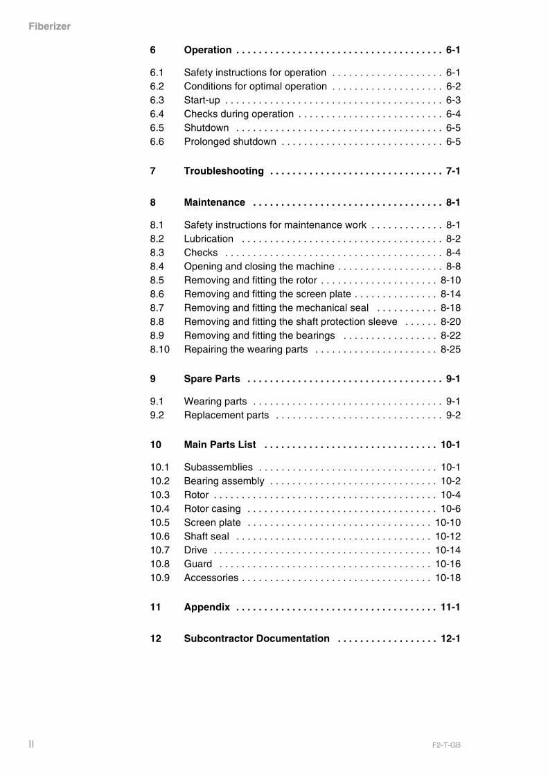
6 Operation . . . . . . . . . . . . . . . . . . . . . . . . . . . . . . . . . . . . . 6-1
6.1 Safety instructions for operation . . . . . . . . . . . . . . . . . . . . 6-16.2 Conditions for optimal operation . . . . . . . . . . . . . . . . . . . . 6-26.3 Start-up . . . . . . . . . . . . . . . . . . . . . . . . . . . . . . . . . . . . . . . 6-36.4 Checks during operation . . . . . . . . . . . . . . . . . . . . . . . . . . 6-46.5 Shutdown . . . . . . . . . . . . . . . . . . . . . . . . . . . . . . . . . . . . . 6-56.6 Prolonged shutdown . . . . . . . . . . . . . . . . . . . . . . . . . . . . . 6-5
7 Troubleshooting . . . . . . . . . . . . . . . . . . . . . . . . . . . . . . . 7-1
8 Maintenance . . . . . . . . . . . . . . . . . . . . . . . . . . . . . . . . . . 8-1
8.1 Safety instructions for maintenance work . . . . . . . . . . . . . 8-18.2 Lubrication . . . . . . . . . . . . . . . . . . . . . . . . . . . . . . . . . . . . 8-28.3 Checks . . . . . . . . . . . . . . . . . . . . . . . . . . . . . . . . . . . . . . . 8-48.4 Opening and closing the machine . . . . . . . . . . . . . . . . . . . 8-88.5 Removing and fitting the rotor . . . . . . . . . . . . . . . . . . . . . 8-108.6 Removing and fitting the screen plate . . . . . . . . . . . . . . . 8-148.7 Removing and fitting the mechanical seal . . . . . . . . . . . 8-188.8 Removing and fitting the shaft protection sleeve . . . . . . 8-208.9 Removing and fitting the bearings . . . . . . . . . . . . . . . . . 8-228.10 Repairing the wearing parts . . . . . . . . . . . . . . . . . . . . . . 8-25
9 Spare Parts . . . . . . . . . . . . . . . . . . . . . . . . . . . . . . . . . . . 9-1
9.1 Wearing parts . . . . . . . . . . . . . . . . . . . . . . . . . . . . . . . . . . 9-19.2 Replacement parts . . . . . . . . . . . . . . . . . . . . . . . . . . . . . . 9-2
10 Main Parts List . . . . . . . . . . . . . . . . . . . . . . . . . . . . . . . 10-1
10.1 Subassemblies . . . . . . . . . . . . . . . . . . . . . . . . . . . . . . . . 10-110.2 Bearing assembly . . . . . . . . . . . . . . . . . . . . . . . . . . . . . . 10-210.3 Rotor . . . . . . . . . . . . . . . . . . . . . . . . . . . . . . . . . . . . . . . . 10-410.4 Rotor casing . . . . . . . . . . . . . . . . . . . . . . . . . . . . . . . . . . 10-610.5 Screen plate . . . . . . . . . . . . . . . . . . . . . . . . . . . . . . . . . 10-1010.6 Shaft seal . . . . . . . . . . . . . . . . . . . . . . . . . . . . . . . . . . . 10-1210.7 Drive . . . . . . . . . . . . . . . . . . . . . . . . . . . . . . . . . . . . . . . 10-1410.8 Guard . . . . . . . . . . . . . . . . . . . . . . . . . . . . . . . . . . . . . . 10-1610.9 Accessories . . . . . . . . . . . . . . . . . . . . . . . . . . . . . . . . . . 10-18
11 Appendix . . . . . . . . . . . . . . . . . . . . . . . . . . . . . . . . . . . . 11-1
12 Subcontractor Documentation . . . . . . . . . . . . . . . . . . 12-1
II F2-T-GB
Fiberizer
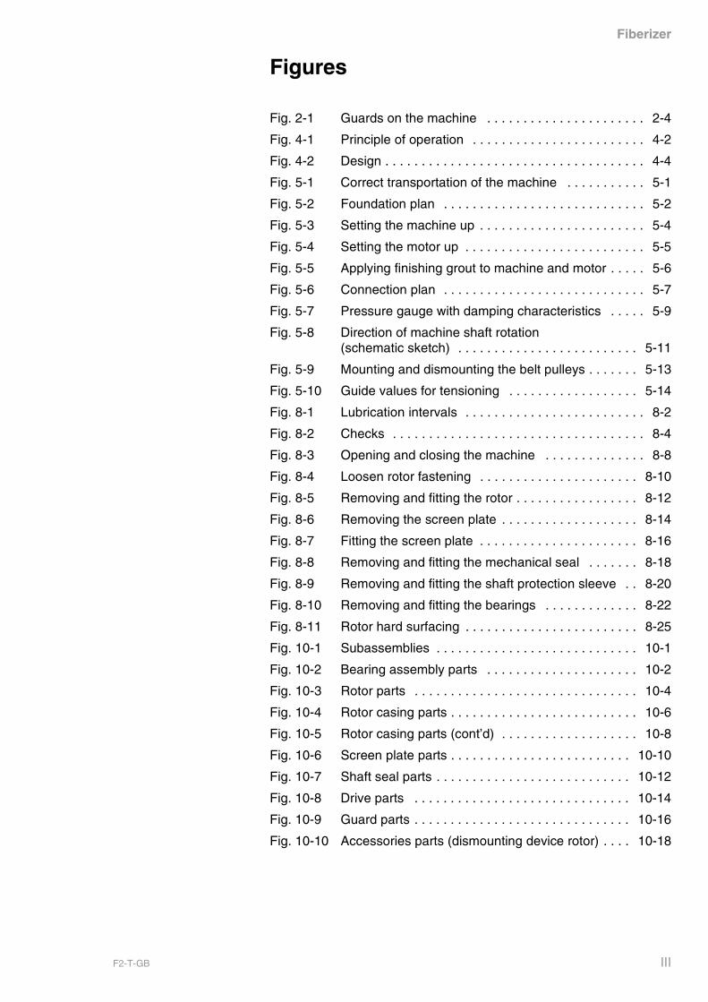
Figures
Fig. 2-1 Guards on the machine . . . . . . . . . . . . . . . . . . . . . . 2-4
Fig. 4-1 Principle of operation . . . . . . . . . . . . . . . . . . . . . . . . 4-2
Fig. 4-2 Design . . . . . . . . . . . . . . . . . . . . . . . . . . . . . . . . . . . . 4-4
Fig. 5-1 Correct transportation of the machine . . . . . . . . . . . 5-1
Fig. 5-2 Foundation plan . . . . . . . . . . . . . . . . . . . . . . . . . . . . 5-2
Fig. 5-3 Setting the machine up . . . . . . . . . . . . . . . . . . . . . . . 5-4
Fig. 5-4 Setting the motor up . . . . . . . . . . . . . . . . . . . . . . . . . 5-5
Fig. 5-5 Applying finishing grout to machine and motor . . . . . 5-6
Fig. 5-6 Connection plan . . . . . . . . . . . . . . . . . . . . . . . . . . . . 5-7
Fig. 5-7 Pressure gauge with damping characteristics . . . . . 5-9
Fig. 5-8 Direction of machine shaft rotation (schematic sketch) . . . . . . . . . . . . . . . . . . . . . . . . . 5-11
Fig. 5-9 Mounting and dismounting the belt pulleys . . . . . . . 5-13
Fig. 5-10 Guide values for tensioning . . . . . . . . . . . . . . . . . . 5-14
Fig. 8-1 Lubrication intervals . . . . . . . . . . . . . . . . . . . . . . . . . 8-2
Fig. 8-2 Checks . . . . . . . . . . . . . . . . . . . . . . . . . . . . . . . . . . . 8-4
Fig. 8-3 Opening and closing the machine . . . . . . . . . . . . . . 8-8
Fig. 8-4 Loosen rotor fastening . . . . . . . . . . . . . . . . . . . . . . 8-10
Fig. 8-5 Removing and fitting the rotor . . . . . . . . . . . . . . . . . 8-12
Fig. 8-6 Removing the screen plate . . . . . . . . . . . . . . . . . . . 8-14
Fig. 8-7 Fitting the screen plate . . . . . . . . . . . . . . . . . . . . . . 8-16
Fig. 8-8 Removing and fitting the mechanical seal . . . . . . . 8-18
Fig. 8-9 Removing and fitting the shaft protection sleeve . . 8-20
Fig. 8-10 Removing and fitting the bearings . . . . . . . . . . . . . 8-22
Fig. 8-11 Rotor hard surfacing . . . . . . . . . . . . . . . . . . . . . . . . 8-25
Fig. 10-1 Subassemblies . . . . . . . . . . . . . . . . . . . . . . . . . . . . 10-1
Fig. 10-2 Bearing assembly parts . . . . . . . . . . . . . . . . . . . . . 10-2
Fig. 10-3 Rotor parts . . . . . . . . . . . . . . . . . . . . . . . . . . . . . . . 10-4
Fig. 10-4 Rotor casing parts . . . . . . . . . . . . . . . . . . . . . . . . . . 10-6
Fig. 10-5 Rotor casing parts (cont’d) . . . . . . . . . . . . . . . . . . . 10-8
Fig. 10-6 Screen plate parts . . . . . . . . . . . . . . . . . . . . . . . . . 10-10
Fig. 10-7 Shaft seal parts . . . . . . . . . . . . . . . . . . . . . . . . . . . 10-12
Fig. 10-8 Drive parts . . . . . . . . . . . . . . . . . . . . . . . . . . . . . . 10-14
Fig. 10-9 Guard parts . . . . . . . . . . . . . . . . . . . . . . . . . . . . . . 10-16
Fig. 10-10 Accessories parts (dismounting device rotor) . . . . 10-18
F2-T-GB III

Fiberizer
IV F2-T-GB
Fiberizer
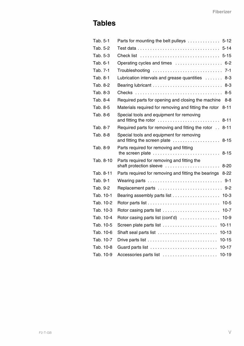
Tables
Tab. 5-1 Parts for mounting the belt pulleys . . . . . . . . . . . . . 5-12
Tab. 5-2 Test data . . . . . . . . . . . . . . . . . . . . . . . . . . . . . . . . . 5-14
Tab. 5-3 Check list . . . . . . . . . . . . . . . . . . . . . . . . . . . . . . . . 5-15
Tab. 6-1 Operating cycles and times . . . . . . . . . . . . . . . . . . . 6-2
Tab. 7-1 Troubleshooting . . . . . . . . . . . . . . . . . . . . . . . . . . . . 7-1
Tab. 8-1 Lubrication intervals and grease quantities . . . . . . . 8-3
Tab. 8-2 Bearing lubricant . . . . . . . . . . . . . . . . . . . . . . . . . . . . 8-3
Tab. 8-3 Checks . . . . . . . . . . . . . . . . . . . . . . . . . . . . . . . . . . . 8-5
Tab. 8-4 Required parts for opening and closing the machine 8-8
Tab. 8-5 Materials required for removing and fitting the rotor 8-11
Tab. 8-6 Special tools and equipment for removing and fitting the rotor . . . . . . . . . . . . . . . . . . . . . . . . . 8-11
Tab. 8-7 Required parts for removing and fitting the rotor . . 8-11
Tab. 8-8 Special tools and equipment for removing and fitting the screen plate . . . . . . . . . . . . . . . . . . . 8-15
Tab. 8-9 Parts required for removing and fitting the screen plate . . . . . . . . . . . . . . . . . . . . . . . . . . . 8-15
Tab. 8-10 Parts required for removing and fitting the shaft protection sleeve . . . . . . . . . . . . . . . . . . . . . . 8-20
Tab. 8-11 Parts required for removing and fitting the bearings 8-22
Tab. 9-1 Wearing parts . . . . . . . . . . . . . . . . . . . . . . . . . . . . . . 9-1
Tab. 9-2 Replacement parts . . . . . . . . . . . . . . . . . . . . . . . . . . 9-2
Tab. 10-1 Bearing assembly parts list . . . . . . . . . . . . . . . . . . . 10-3
Tab. 10-2 Rotor parts list . . . . . . . . . . . . . . . . . . . . . . . . . . . . . 10-5
Tab. 10-3 Rotor casing parts list . . . . . . . . . . . . . . . . . . . . . . . 10-7
Tab. 10-4 Rotor casing parts list (cont’d) . . . . . . . . . . . . . . . . 10-9
Tab. 10-5 Screen plate parts list . . . . . . . . . . . . . . . . . . . . . . 10-11
Tab. 10-6 Shaft seal parts list . . . . . . . . . . . . . . . . . . . . . . . . 10-13
Tab. 10-7 Drive parts list . . . . . . . . . . . . . . . . . . . . . . . . . . . . 10-15
Tab. 10-8 Guard parts list . . . . . . . . . . . . . . . . . . . . . . . . . . . 10-17
Tab. 10-9 Accessories parts list . . . . . . . . . . . . . . . . . . . . . . 10-19
F2-T-GB V

Fiberizer
VI F2-T-GB
Fiberizer
These operating instructions are to familiarize the user with themachine. They contain a description of the machine‘s design and itsprinciple of operation. Following these operating instructions ensuresrapid and safe start-up and maintenance of the machine.
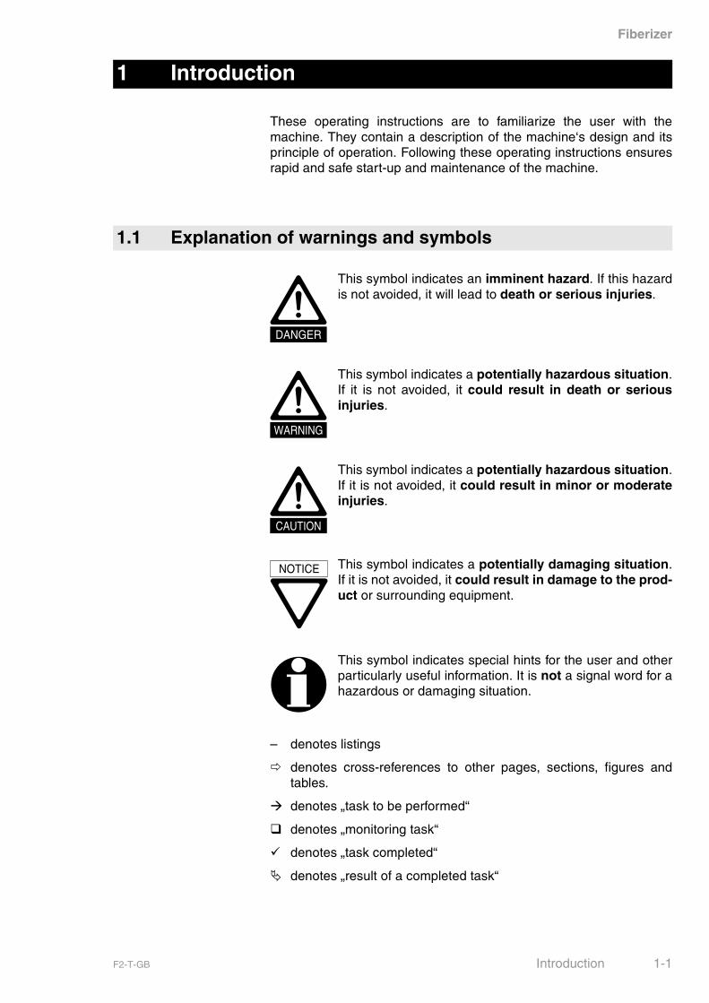
– denotes listings
� denotes cross-references to other pages, sections, figures andtables.
� denotes „task to be performed“
� denotes „monitoring task“
� denotes „task completed“
� denotes „result of a completed task“
1 Introduction
1.1 Explanation of warnings and symbols
DANGER
This symbol indicates an imminent hazard. If this hazardis not avoided, it will lead to death or serious injuries.
WARNING
This symbol indicates a potentially hazardous situation.If it is not avoided, it could result in death or seriousinjuries.
CAUTION
This symbol indicates a potentially hazardous situation.If it is not avoided, it could result in minor or moderateinjuries.
NOTICE This symbol indicates a potentially damaging situation.If it is not avoided, it could result in damage to the prod-uct or surrounding equipment.
This symbol indicates special hints for the user and otherparticularly useful information. It is not a signal word for ahazardous or damaging situation.
F2-T-GB Introduction 1-1
Fiberizer
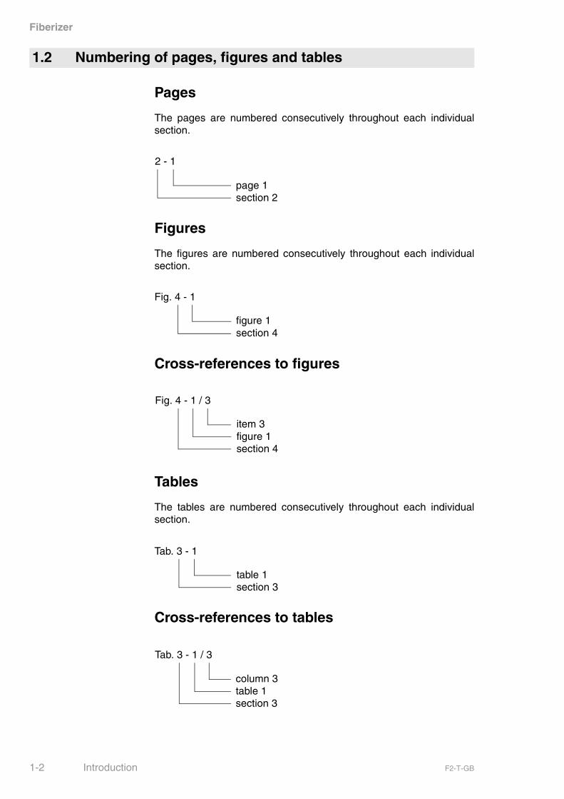
Pages
The pages are numbered consecutively throughout each individualsection.
Figures
The figures are numbered consecutively throughout each individualsection.
Cross-references to figures
Tables
The tables are numbered consecutively throughout each individualsection.
Cross-references to tables
1.2 Numbering of pages, figures and tables
2 - 1
page 1section 2
Fig. 4 - 1
figure 1section 4
Fig. 4 - 1 / 3
item 3figure 1section 4
Tab. 3 - 1
table 1section 3
Tab. 3 - 1 / 3
column 3table 1section 3
1-2 Introduction F2-T-GB
Fiberizer
Sec. Section
Fig. Figure
Tab. Table
Cont’d Continued
Unless specified otherwise, all dimensions are in mm.
1.3 Abbreviations
1.4 Dimensions
F2-T-GB Introduction 1-3

Fiberizer
1-4 Introduction F2-T-GB

Fiberizer
For operation of the machine, the local safety and accident preventionrules and regulations are in any case binding.
State of the art
This VOITH SULZER stock preparation machine has been built inaccordance with state-of-the-art standards and the recognized safetyrules. Nevertheless, its use may constitute a risk to life and limb of theuser or of third parties, or cause damage to the machine and to othermaterial property, if:
– the machine is not used as designated,
– the machine is operated by untrained personnel,
– the machine is modified or converted improperly and/or
– the safety instructions are not observed.
Therefore, every person involved in erecting, operating, inspecting,maintaining, servicing and repairing the machine must read, under-stand and observe the complete operating instructions, particularlythe Safety Instructions.
Preconditions for using the machine:
The machine may only be used:
– in perfect technical condition,
– as designated,
– according to the instructions set out in the operating manual, andonly by safety-conscious persons who are fully aware of the risksinvolved in operating the machine,
– if all safety devices and emergency shut-off components are fittedand operative.
Any functional disorders, especially those affecting the safety of themachine, must therefore be rectified immediately.
2 Safety Instructions
2.1 General safety instructions
F2-T-GB Safety Instructions 2-1
Fiberizer
Use
The Fiberizer is used for
– the wet preparation of waste paper,
– the removal of contaminants and for the forward screening of dis-integrated fibres.
Liability for non-designated use
Using the machine for purposes other than those mentioned above isconsidered contrary to its designated use. VOITH SULZER Stoffauf-bereitung GmbH & Co. KG cannot be held liable for any resultingdamage. The risk of such misuse lies entirely with the user.
Availability of operating instructions
The operating instructions must be available wherever the machine isin use.
Additional regulations
In addition to the operating instructions, observe all other generallyapplicable legal and other mandatory regulations relevant to accidentprevention and environmental protection and instruct the personnel tocomply with them.
Additional instructions
Supplement the operating manual by instructions covering the dutiesinvolved in supervising and notifying special organizational features,such as job organisation, working sequence or the personnelentrusted with the work.
Checks
Check regularly whether the personnel carries out the work in compli-ance with the operating instructions and whether they pay attention torisks and safety factors.
2.2 Designated use of the machine
2.3 Organizational measures
2-2 Safety Instructions F2-T-GB
Fiberizer
Protective equipment
Use protective equipment wherever and whenever required.
Safety instructions and warnings
Observe all safety instructions and warnings attached to the machine.Make sure that these signs are legible and replace damaged andillegible plates.
Modifications or changes in operating conditions
In the event of safety-relevant machine modifications or changes inoperating conditions, stop the machine immediately and report themalfunction to the person responsible for the machine.
Rebuilds or modifications
Never make any unauthorized rebuilds and modifications which mightimpair safety. Any verbal agreements with the manufacturer or thedesign engineer require written confirmation.
Replacing damaged parts
Parts of the machine that are not in perfect working order must bereplaced immediately with original spare parts (� Sec. 9, Spare Partson page 9-1).
Use only original spare and wearing parts from VOITH SULZER Stof-faufbereitung GmbH & Co. KG! Unauthorized parts provide no guar-antee that they have been designed and manufactured according tothe application. Danger of accidents!
Checks and maintenance
Adhere to prescribed intervals or intervals specified in the operatinginstructions for routine checks and maintenance work.
Working with hazardous substances
Make sure that dangers to the environment caused by hazardoussubstances are precluded when working on lubricating systems anddevices and when cleaning the machine with solvent-containingdetergents.
Lifting gears
Make sure that the lifting capacity of the lifting gears to be properlyinstalled is at least equal to the weight of the machine or of the partsto be lifted (� Sec. 3.3, Weights on page 3-1).
F2-T-GB Safety Instructions 2-3
Fiberizer
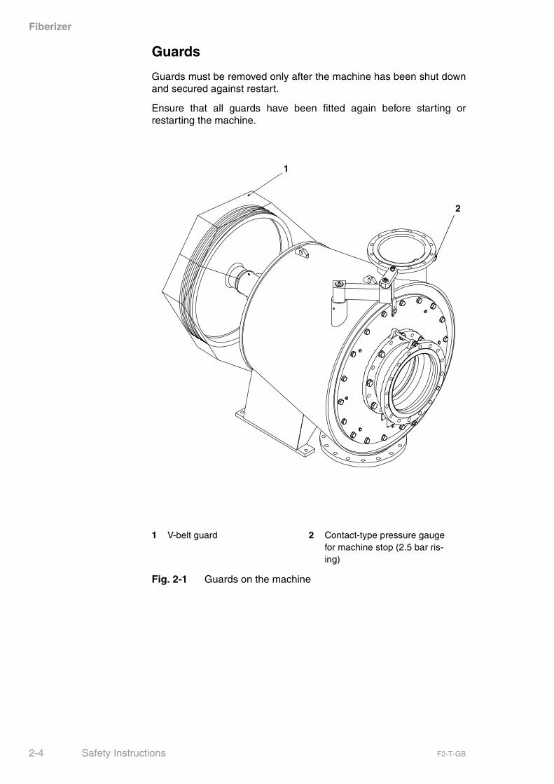
Guards
Guards must be removed only after the machine has been shut downand secured against restart.
Ensure that all guards have been fitted again before starting orrestarting the machine.
1 V-belt guard 2 Contact-type pressure gauge for machine stop (2.5 bar ris-ing)
Fig. 2-1 Guards on the machine
1
2
2-4 Safety Instructions F2-T-GB

Fiberizer
Qualification of personnel
Any work on the machine must be executed only by trained andinstructed personnel authorized by the owner.
Responsibilities
Responsibilities in the operation of the machine must be clearlyestablished and observed, so that no unclear competences mightimpair safety.
Instructions contrary to safety
Give the operator the authority to refuse instructions by third partiesthat are contrary to safety.
Maintenance and repair
Maintenance and repair demand special knowledge and may only becarried out by trained technical specialists.
Depending on the operating conditions, place of installation, piperuns, and other unit parts, the machine may produce a noise levelwhich exceeds 80 dB (A).
Therefore, wear appropriate ear protection when working in the imme-diate vicinity of the machine in operation.
In general, the machine is operated/controlled from a sound-proofoperating room.
2.4 Selection and qualification of personnel
2.5 Noise protection
F2-T-GB Safety Instructions 2-5

Fiberizer
Entanglement, crushing and cut/sever hazards due to:
– moving machine parts left exposed by removing covers for inspec-tion, sampling, etc.,
– running and exposed shafts, cylinders, drums, or belts,
– automatically operated discharge valve traps.
Burning or scalding hazards when
opening or keeping open function-check and/or sampling openings onequipment operating at high temperatures (above 40°C).
Harmful gases and vapours
Open covers may allow harmful gases or vapours to escape into theatmosphere.
2.6 Additional hazards
2-6 Safety Instructions F2-T-GB
Fiberizer
3 Technical Data
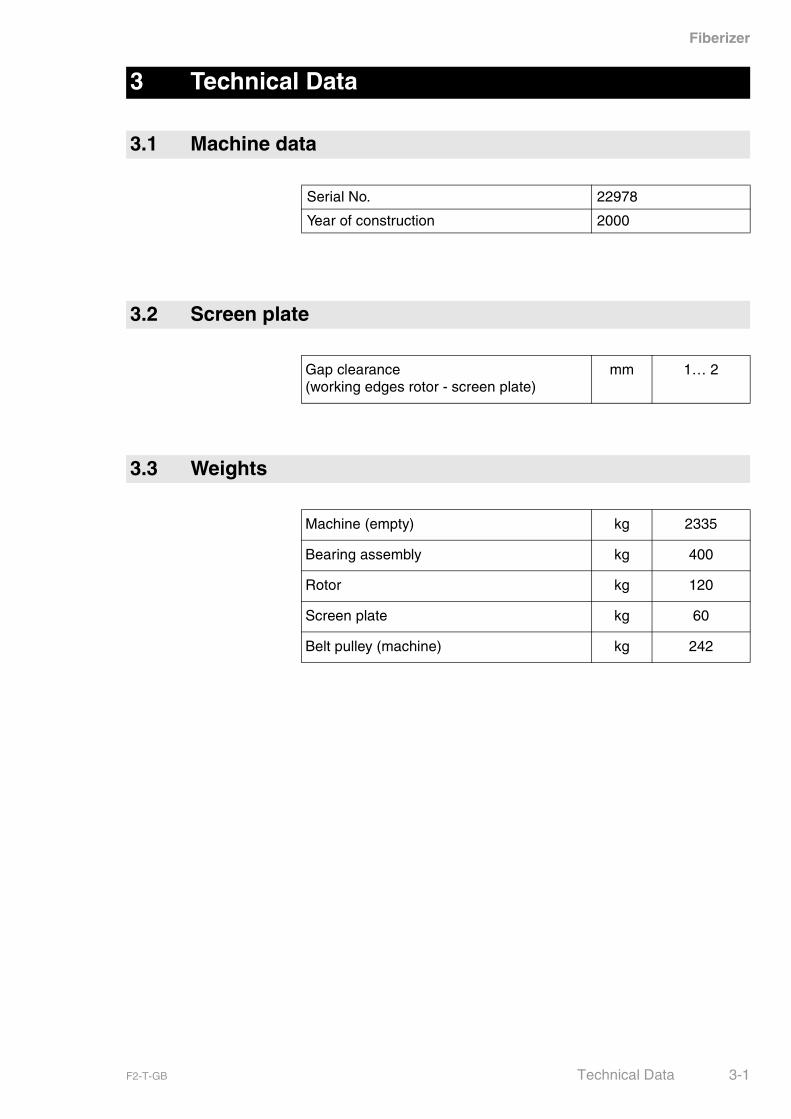
3.1 Machine data
Serial No. 22978
Year of construction 2000
3.2 Screen plate
Gap clearance (working edges rotor - screen plate)
mm 1… 2
3.3 Weights
Machine (empty) kg 2335
Bearing assembly kg 400
Rotor kg 120
Screen plate kg 60
Belt pulley (machine) kg 242
F2-T-GB Technical Data 3-1
Fiberizer
Motor
Belt data
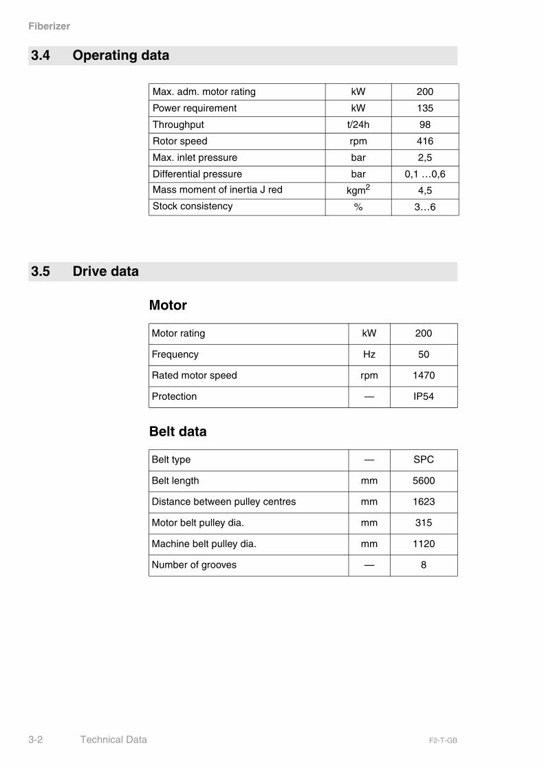
3.4 Operating data
Max. adm. motor rating kW 200
Power requirement kW 135
Throughput t/24h 98
Rotor speed rpm 416
Max. inlet pressure bar 2,5
Differential pressure bar 0,1 …0,6
Mass moment of inertia J red kgm2 4,5
Stock consistency % 3…6
3.5 Drive data
Motor rating kW 200
Frequency Hz 50
Rated motor speed rpm 1470
Protection — IP54
Belt type — SPC
Belt length mm 5600
Distance between pulley centres mm 1623
Motor belt pulley dia. mm 315
Machine belt pulley dia. mm 1120
Number of grooves — 8
3-2 Technical Data F2-T-GB

Fiberizer
The Fiberizer is used for
– the wet preparation of waste paper,
– the removal of contaminants and for the forward screening of dis-integrated fibres.
4 Technical Description
4.1 Use
F2-T-GB Technical Description 4-1

Fiberizer
4.2 Principle of operation
1 Fiberizer 2 Screen plate ribs 3 Rotor
Fig. 4-1 Principle of operation
3
21
LightweightRejects
Inlet
Accept
HeavyRejects
4-2 Technical Description F2-T-GB
Fiberizer
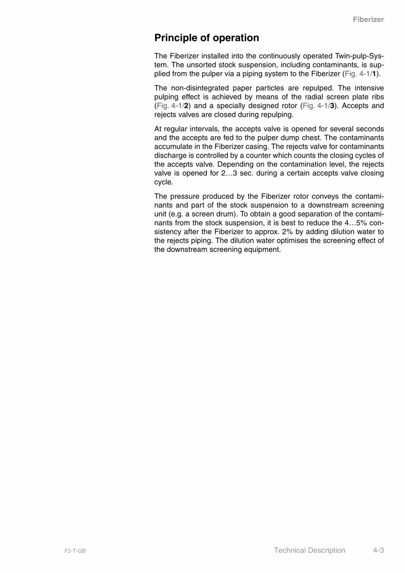
Principle of operation
The Fiberizer installed into the continuously operated Twin-pulp-Sys-tem. The unsorted stock suspension, including contaminants, is sup-plied from the pulper via a piping system to the Fiberizer (Fig. 4-1/1).
The non-disintegrated paper particles are repulped. The intensivepulping effect is achieved by means of the radial screen plate ribs(Fig. 4-1/2) and a specially designed rotor (Fig. 4-1/3). Accepts andrejects valves are closed during repulping.
At regular intervals, the accepts valve is opened for several secondsand the accepts are fed to the pulper dump chest. The contaminantsaccumulate in the Fiberizer casing. The rejects valve for contaminantsdischarge is controlled by a counter which counts the closing cycles ofthe accepts valve. Depending on the contamination level, the rejectsvalve is opened for 2…3 sec. during a certain accepts valve closingcycle.
The pressure produced by the Fiberizer rotor conveys the contami-nants and part of the stock suspension to a downstream screeningunit (e.g. a screen drum). To obtain a good separation of the contami-nants from the stock suspension, it is best to reduce the 4…5% con-sistency after the Fiberizer to approx. 2% by adding dilution water tothe rejects piping. The dilution water optimises the screening effect ofthe downstream screening equipment.
F2-T-GB Technical Description 4-3

Fiberizer
4.3 Design
1 Bearing assembly 4 Shrink disc 6 Rotor casing
2 Shaft seal 5 Rotor 7 Swing cover
3 Screen plate
Fig. 4-2 Design
2 41 3
5 6 7
4-4 Technical Description F2-T-GB
Fiberizer
� Loosen machine fixing.
� Check consignment against delivery note for completeness.
� Check consignment for transport damage.
� Report any transport damage immediately toVOITH SULZER Stoffaufbereitung GmbH & Co. KG
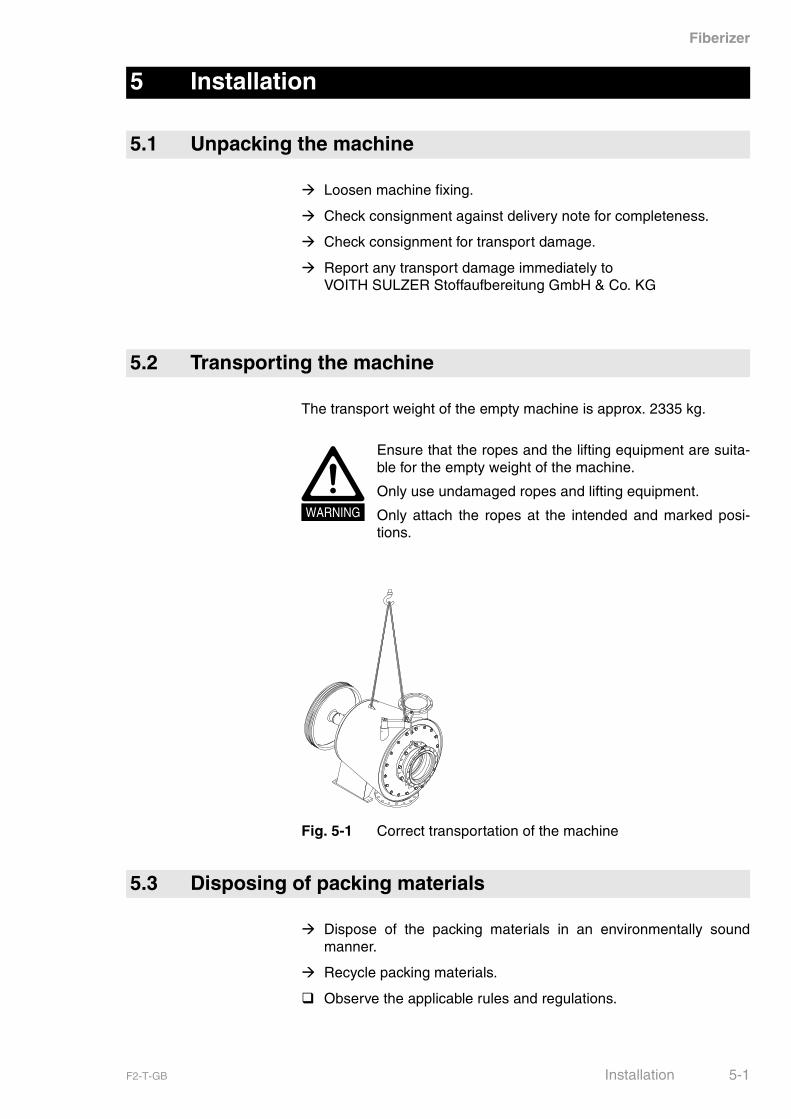
The transport weight of the empty machine is approx. 2335 kg.
Fig. 5-1 Correct transportation of the machine
� Dispose of the packing materials in an environmentally soundmanner.
� Recycle packing materials.
� Observe the applicable rules and regulations.
5 Installation
5.1 Unpacking the machine
5.2 Transporting the machine
WARNING
Ensure that the ropes and the lifting equipment are suita-ble for the empty weight of the machine.
Only use undamaged ropes and lifting equipment.
Only attach the ropes at the intended and marked posi-tions.
5.3 Disposing of packing materials
F2-T-GB Installation 5-1
Fiberizer
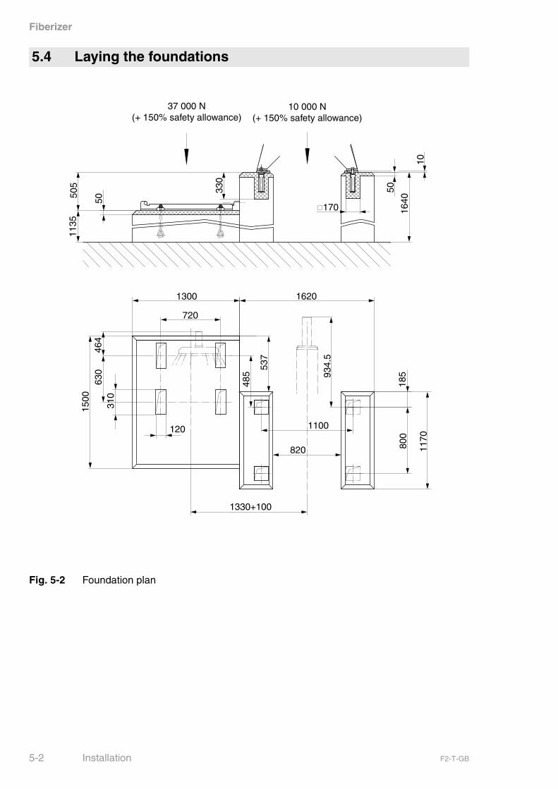
Fig. 5-2 Foundation plan
5.4 Laying the foundations
37 000 N(+ 150% safety allowance)
10 000 N(+ 150% safety allowance)
5-2 Installation F2-T-GB
Fiberizer
General
The foundations are to be laid by the customer.
The foundation plan contains all dimensions necessary to lay thefoundations.
Preconditions
� Location is known and accessible.
� Load capacity of the substructure is sufficient.
� Reinforcement plan is available.
Preparations
� Set up boarding as shown in the foundation plan (� Fig. 5-2,Foundation plan on page 5-2).
� Make and lay reinforcements.
� Fill foundation recesses with filling materials.
Concreting
� Mix and pour concrete and allow to set.
Finishing work
� Remove boarding.
� Remove filling materials.
� Clean recesses.
NOTICE Do not use thinners, otherwise the grout will not harden.
F2-T-GB Installation 5-3
Fiberizer
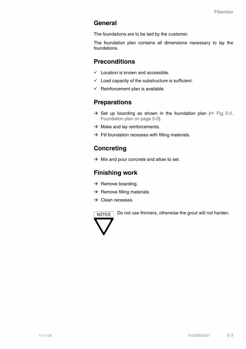
Machine
� Hook machine (Fig. 5-3/2) on a crane (� Fig. 5-1, Correct trans-portation of the machine on page 5-1).
� Fasten foundation blocks to machine with hexagon screws(Fig. 5-3/3).
� Position flat steel (Fig. 5-3/4).
� Turn in setscrew (Fig. 5-3/5) to the specified depth.
� Lower machine onto flat steel.
� Position machine as shown in foundation plan.
� Align machine horizontally by turning the setscrews (Fig. 5-3/5).
� Mix and pour grout (Fig. 5-3/6) and allow to set.
5.5 Setting up and aligning
1 Foundation blocks 4 Flat steel
2 Machine 5 Setscrew
3 Hex. screws 6 Grout
Fig. 5-3 Setting the machine up
30
1
4
3 2
5
6
5-4 Installation F2-T-GB
Fiberizer
Motor
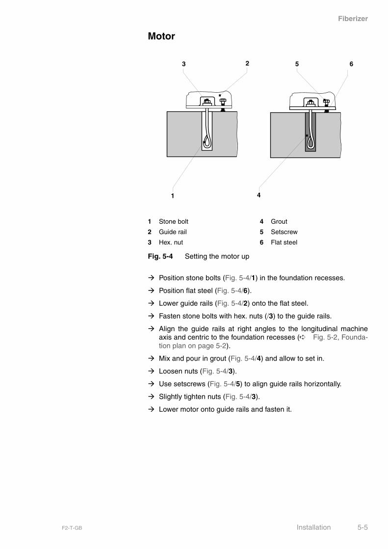
� Position stone bolts (Fig. 5-4/1) in the foundation recesses.
� Position flat steel (Fig. 5-4/6).
� Lower guide rails (Fig. 5-4/2) onto the flat steel.
� Fasten stone bolts with hex. nuts (/3) to the guide rails.
� Align the guide rails at right angles to the longitudinal machineaxis and centric to the foundation recesses (➪ Fig. 5-2, Founda-tion plan on page 5-2).
� Mix and pour in grout (Fig. 5-4/4) and allow to set in.
� Loosen nuts (Fig. 5-4/3).
� Use setscrews (Fig. 5-4/5) to align guide rails horizontally.
� Slightly tighten nuts (Fig. 5-4/3).
� Lower motor onto guide rails and fasten it.
1 Stone bolt 4 Grout
2 Guide rail 5 Setscrew
3 Hex. nut 6 Flat steel
Fig. 5-4 Setting the motor up
1 4
3 2 5 6
F2-T-GB Installation 5-5
Fiberizer
Machine and motor grouting
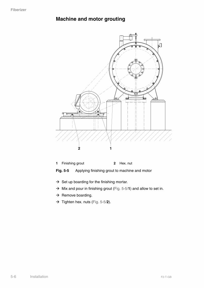
� Set up boarding for the finishing mortar.
� Mix and pour in finishing grout (Fig. 5-5/1) and allow to set in.
� Remove boarding.
� Tighten hex. nuts (Fig. 5-5/2).
1 Finishing grout 2 Hex. nut
Fig. 5-5 Applying finishing grout to machine and motor
12
5-6 Installation F2-T-GB

Fiberizer
Fig. 5-6 Connection plan
5.6 Connecting
Stock pipe connecting dimensions
F2-T-GB Installation 5-7
Fiberizer
Preconditions
� Machine and motor with guide rails are anchored securely to thefoundations.
Machine
Pipework
The inlet and outlet circuits can be positioned more or less asrequired. In order to avoid disturbing deposits, for example in deadcorners, the single pieces of pipework should be flanged exactly cen-tric.
Sealing-water piping
� Install sealing-water piping.
Sampling ports
Sampling valves must be fitted in all stock-conducting pipes by thecustomer on site.
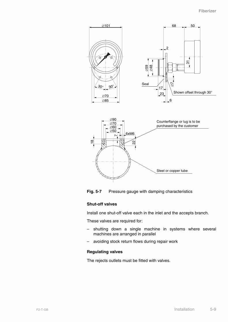
Pressure gauges
Fit one pressure gauge each in the inlet branch and the acceptsbranch of the machine to monitor the differential pressure.
The pressure gauges have:
– a pressure range of 0…6 bar and
– vibration damping characteristics.
They are also fitted with the required connecting lugs (� Fig. 5-7,Pressure gauge with damping characteristics on page 5-9).
NOTICE All pipework must be connected completely free of ten-sion.
Do not join pipes with force using the fastening screws.
Support and suspend pipework so that it does not swingor affect the machine during operation, for examplethrough pipework expansion caused by heat.
Locate the pressure gauges at the same height. if this isnot possible, take differential pressure into account.
5-8 Installation F2-T-GB
Fiberizer
Fig. 5-7 Pressure gauge with damping characteristics
Shut-off valves
Install one shut-off valve each in the inlet and the accepts branch.
These valves are required for:
– shutting down a single machine in systems where severalmachines are arranged in parallel
– avoiding stock return flows during repair work
Regulating valves
The rejects outlets must be fitted with valves.
∅101
30°30°
∅70∅85
∅50∅60
∅90
2218
∅70
6xM6
5068
31
∅59
∅48
17
23
6
2
∅7
7
Shown offset through 30°
Counterflange or lug is to be purchased by the customer
Steel or copper tube
Seal
F2-T-GB Installation 5-9
Fiberizer
Motor
Preconditions
� Motor is mounted.
Connecting the motor
Connect motor according to the VDE rules VDE/0100 and 0113 or thelocally applicable rules and regulations.
� Connect motor electrically.
� Check connections (� terminal diagram of motor supplier).
Emergency stop switch
Install emergency stop switch in the vicinity of the machine.
For safety reasons, we recommend to install a lockable3-pole safety main switch with padlock.
The power supply circuits are to be routed in such a waythat the entire adjusting range of the motor can be cov-ered without disconnecting the lines.
5-10 Installation F2-T-GB

Fiberizer
Checking the direction of rotation
� Switch motor on for a short time.
Fig. 5-8 Direction of machine shaft rotation (schematic sketch)
� Switch motor off.
5.7 Checking the direction of rotation
WARNING
Check the direction of rotation only after V-belt has beenremoved.
Possible danger of injury due to the dismounted belt.
If the machine is not disconnected, the shaft seal couldrun dry and thus be damaged.
The motor shaft must rotate in such a way that the follow-ing direction of machine shaft rotation is obtained whenconsidering the specific arrangement.
Drive journal of the machine
F2-T-GB Installation 5-11
Fiberizer
Preconditions
� The main switch is switched off and secured against unintentionalrestart.
� Belt is dismounted.
Required parts
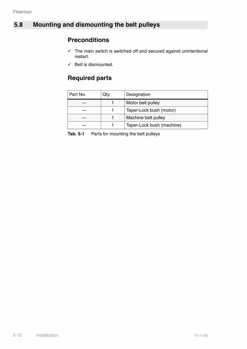
5.8 Mounting and dismounting the belt pulleys
Part No. Qty. Designation
— 1 Motor belt pulley
— 1 Taper-Lock bush (motor)
— 1 Machine belt pulley
— 1 Taper-Lock bush (machine)
Tab. 5-1 Parts for mounting the belt pulleys
5-12 Installation F2-T-GB
Fiberizer
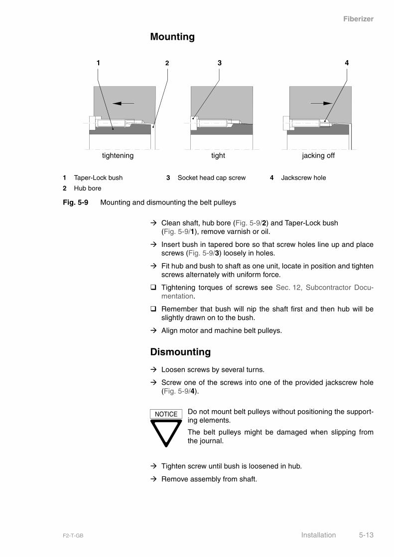
Mounting
� Clean shaft, hub bore (Fig. 5-9/2) and Taper-Lock bush (Fig. 5-9/1), remove varnish or oil.
� Insert bush in tapered bore so that screw holes line up and placescrews (Fig. 5-9/3) loosely in holes.
� Fit hub and bush to shaft as one unit, locate in position and tightenscrews alternately with uniform force.
� Tightening torques of screws see Sec. 12, Subcontractor Docu-mentation.
� Remember that bush will nip the shaft first and then hub will beslightly drawn on to the bush.
� Align motor and machine belt pulleys.
Dismounting
� Loosen screws by several turns.
� Screw one of the screws into one of the provided jackscrew hole(Fig. 5-9/4).
� Tighten screw until bush is loosened in hub.
� Remove assembly from shaft.
1 Taper-Lock bush 3 Socket head cap screw 4 Jackscrew hole
2 Hub bore
Fig. 5-9 Mounting and dismounting the belt pulleys
jacking offtighttightening
431 2
NOTICE Do not mount belt pulleys without positioning the support-ing elements.
The belt pulleys might be damaged when slipping fromthe journal.
F2-T-GB Installation 5-13
Fiberizer
Preconditions
� The main switch is switched off and secured against unintentionalrestart.
� The belt pulleys are mounted to motor and machine.
To install belts
� Adjust minimum centre distance between motor journal and rotorshaft for belt mounting.
� Install belts.
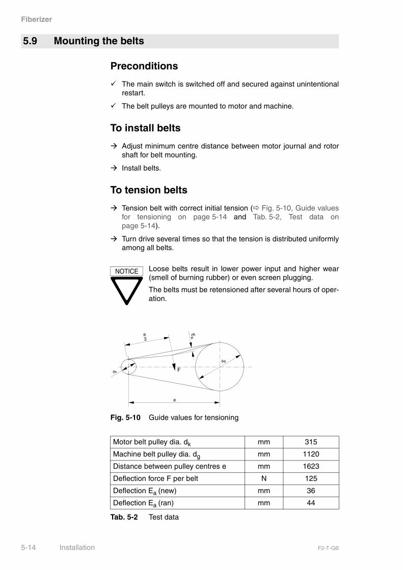
To tension belts
� Tension belt with correct initial tension (� Fig. 5-10, Guide valuesfor tensioning on page 5-14 and Tab. 5-2, Test data onpage 5-14).
� Turn drive several times so that the tension is distributed uniformlyamong all belts.
Fig. 5-10 Guide values for tensioning
5.9 Mounting the belts
NOTICE Loose belts result in lower power input and higher wear(smell of burning rubber) or even screen plugging.
The belts must be retensioned after several hours of oper-ation.
Motor belt pulley dia. dk mm 315
Machine belt pulley dia. dg mm 1120
Distance between pulley centres e mm 1623
Deflection force F per belt N 125
Deflection Ea (new) mm 36
Deflection Ea (ran) mm 44
Tab. 5-2 Test data
e2
Ea
dk
dg
e
F
5-14 Installation F2-T-GB
Fiberizer
Preconditions
� The main switch is switched off and secured against unintentionalstart-up.
Preparations
� Preadjust valve positions and cycles to suit process engineeringconditions (� Tab. 6-1, Operating cycles and times onpage 6-2).
Flushing
� Thoroughly flush inlet piping.
� Close inlet valve.
� Open machine (� Sec. 8.4, Opening and closing the machine onpage 8-8).
� Thoroughly wash down machine with hose.
� Remove any heavy particles which have been flushed into themachine.
Lubrication
� Check grease lubrication for bearings (� Sec. 8.2, Lubrication onpage 8-2).
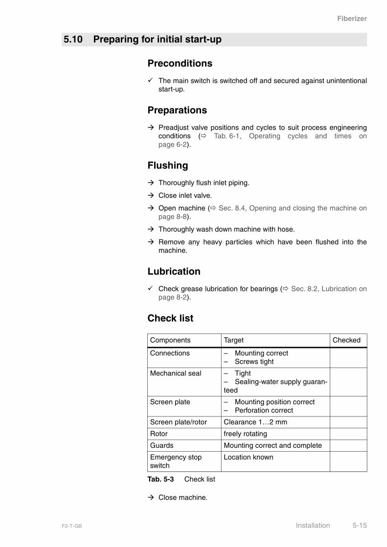
Check list
� Close machine.
5.10 Preparing for initial start-up
Components Target Checked
Connections – Mounting correct– Screws tight
Mechanical seal – Tight– Sealing-water supply guaran-teed
Screen plate – Mounting position correct– Perforation correct
Screen plate/rotor Clearance 1…2 mm
Rotor freely rotating
Guards Mounting correct and complete
Emergency stop switch
Location known
Tab. 5-3 Check list
F2-T-GB Installation 5-15
Fiberizer
The machine is ready for operation when all items on the check listhave been checked.
Trial run
During its trial run, the machine is operated with water. The machineis filled with water, vented and operated without pump pressure (notedown power consumption). Check direction of rotation once againwhen switching the drive motor on (� Sec. 5.7, Checking the direc-tion of rotation on page 5-11).
� Shut machine down (� Sec. 6.5, Shutdown on page 6-5).
� Prepare machine for long-term shutdown (� Sec. 6.6, Prolongedshutdown on page 6-5).
� Dismount all pipework.
� Disconnect supply piping flanges.
� Remove belt guard and belts.
� Loosen foundation fastening.
The machine is now ready for transport.
5.11 Dismounting the machine
5-16 Installation F2-T-GB

Fiberizer
Guards
Rotating parts, such as V-belts, couplings, shafts, rotors, etc. mayseize loose clothes, long hair, jewellery or limbs.
You might get seriously injured or killed.
The machine must never be used without the required guards.
Protection of persons
Unexpected incidents may result in personal injury.
To ensure rapid reaction, always check where the emergency stopswitch is installed and whether it works properly before putting themachine in operation.
Safe operation
This machine is operated under pressure. Therefore, it must bechecked whether all casing covers, inspection ports, windows, etc.are properly locked with undamaged, reliable fasteners.
Covers bursting open can lead to serious injuries and scalding.
The machine must never be used at pressures exceeding the maxi-mum permissible inlet pressure (� Sec. 3.4, Operating data onpage 3-2).
Higher pressures may occur if:
– the stock flow is not ensured, i.e. accepts and rejects valves mustbe open.
– sudden pressure surges when the shut-off elements are shut tooabruptly.
6 Operation
6.1 Safety instructions for operation
F2-T-GB Operation 6-1
Fiberizer
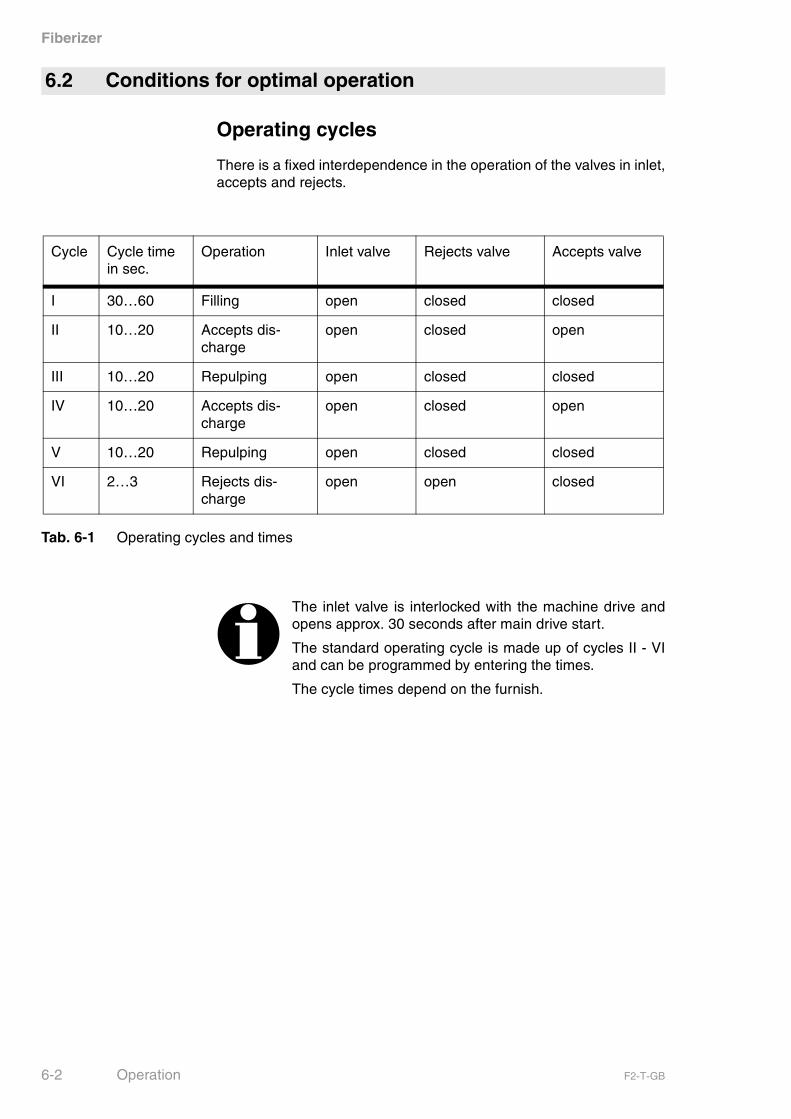
Operating cycles
There is a fixed interdependence in the operation of the valves in inlet,accepts and rejects.
Tab. 6-1 Operating cycles and times
6.2 Conditions for optimal operation
Cycle Cycle time in sec.
Operation Inlet valve Rejects valve Accepts valve
I 30…60 Filling open closed closed
II 10…20 Accepts dis-charge
open closed open
III 10…20 Repulping open closed closed
IV 10…20 Accepts dis-charge
open closed open
V 10…20 Repulping open closed closed
VI 2…3 Rejects dis-charge
open open closed
The inlet valve is interlocked with the machine drive andopens approx. 30 seconds after main drive start.
The standard operating cycle is made up of cycles II - VIand can be programmed by entering the times.
The cycle times depend on the furnish.
6-2 Operation F2-T-GB
Fiberizer
Preconditions
� The main switch is switched off and secured against unintentionalstart-up.
� The preparations for initial start-up must have been completed(� Tab. 5-3, Check list on page 5-15).
Preparations
� Check belt tension (� Tab. 5-2, Test data on page 5-14 undFig. 5-10, Guide values for tensioning on page 5-14).
� Retension belts, if necessary.
� Check bearing lubrication (� Sec. 8.2, Lubrication on page 8-2).
� Check cover fastening and pipe connections for tight fit (no leak-age).
Starting the machine
� Switch main switch and control system on.
� Close all valves.
� Open sealing-water for shaft sealing.
� Fill machine with dilution water.
� Start motor.
� Inlet valve opens after approx. 30 seconds.
� Check cycle sequence of accepts and rejects valves.
Ensure discharge of heavy rejects.
6.3 Start-up
NOTICE Danger of excessive pressure build-up in the rotor casingdue to heated up suspension!
Avoid prolonged operation of the Fibersorter with closedinlet and outlet valves.
F2-T-GB Operation 6-3
Fiberizer
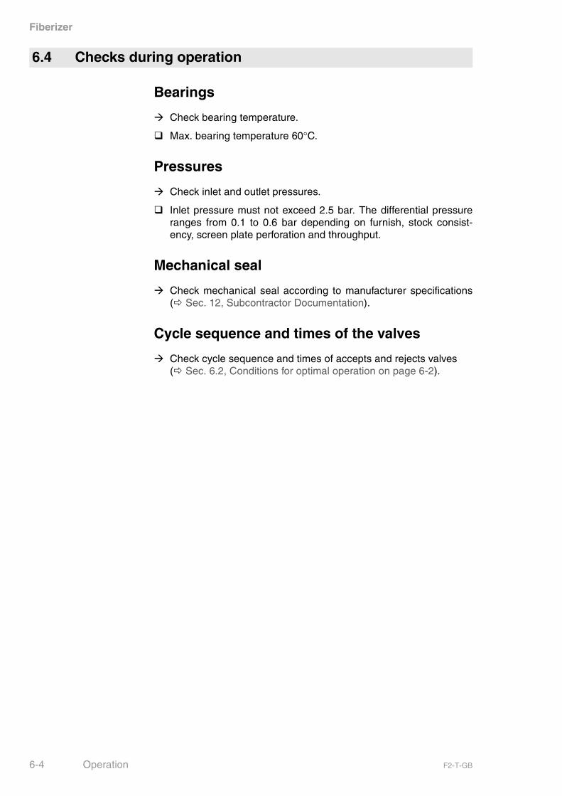
Bearings
� Check bearing temperature.
� Max. bearing temperature 60°C.
Pressures
� Check inlet and outlet pressures.
� Inlet pressure must not exceed 2.5 bar. The differential pressureranges from 0.1 to 0.6 bar depending on furnish, stock consist-ency, screen plate perforation and throughput.
Mechanical seal
� Check mechanical seal according to manufacturer specifications(� Sec. 12, Subcontractor Documentation).
Cycle sequence and times of the valves
� Check cycle sequence and times of accepts and rejects valves (� Sec. 6.2, Conditions for optimal operation on page 6-2).
6.4 Checks during operation
6-4 Operation F2-T-GB
Fiberizer
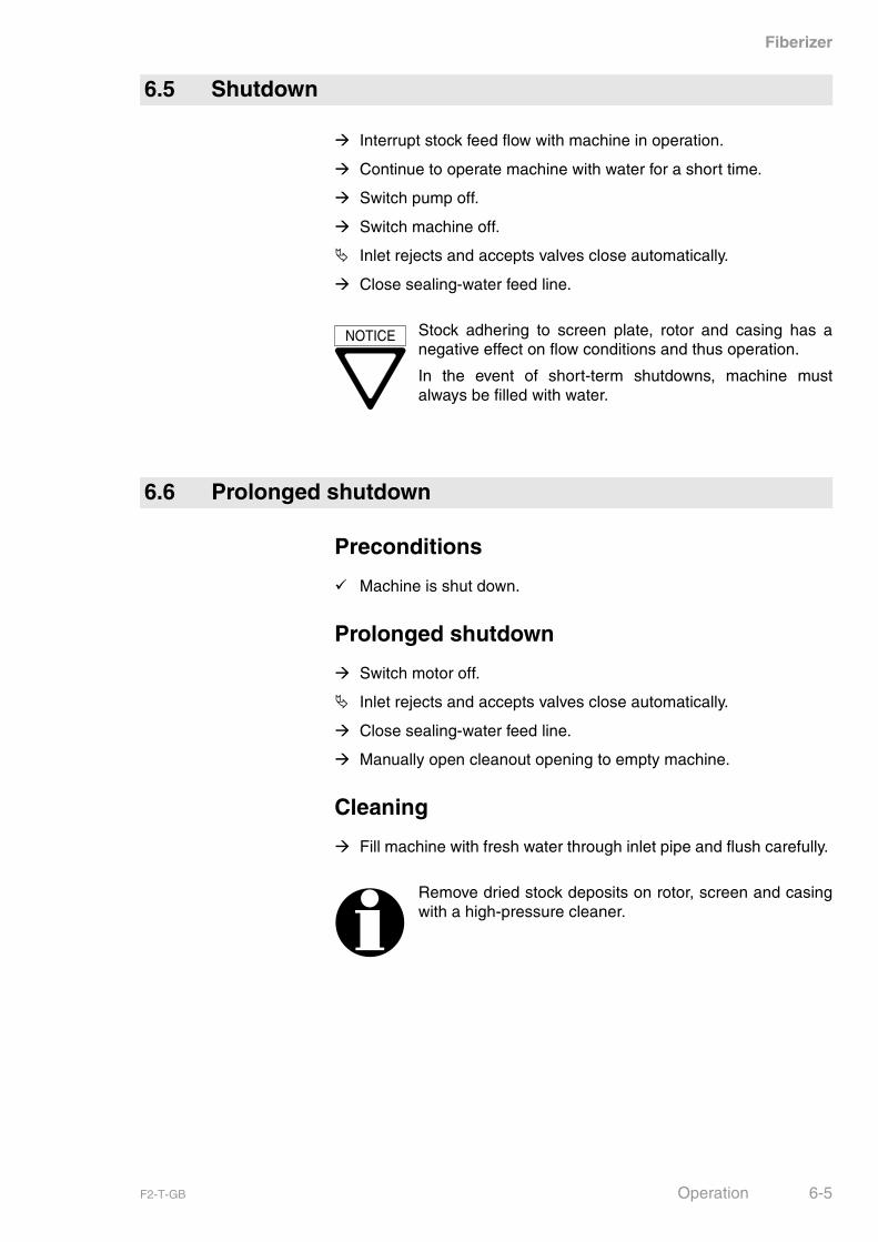
� Interrupt stock feed flow with machine in operation.
� Continue to operate machine with water for a short time.
� Switch pump off.
� Switch machine off.
� Inlet rejects and accepts valves close automatically.
� Close sealing-water feed line.
Preconditions
� Machine is shut down.
Prolonged shutdown
� Switch motor off.
� Inlet rejects and accepts valves close automatically.
� Close sealing-water feed line.
� Manually open cleanout opening to empty machine.
Cleaning
� Fill machine with fresh water through inlet pipe and flush carefully.
6.5 Shutdown
NOTICE Stock adhering to screen plate, rotor and casing has anegative effect on flow conditions and thus operation.
In the event of short-term shutdowns, machine mustalways be filled with water.
6.6 Prolonged shutdown
Remove dried stock deposits on rotor, screen and casingwith a high-pressure cleaner.
F2-T-GB Operation 6-5

Fiberizer
6-6 Operation F2-T-GB
Fiberizer
7 Troubleshooting
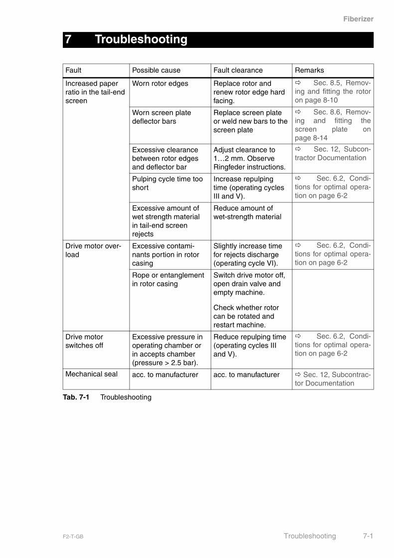
Fault Possible cause Fault clearance Remarks
Increased paper ratio in the tail-end screen
Worn rotor edges Replace rotor and renew rotor edge hard facing.
�� Sec. 8.5, Remov-ing and fitting the rotoron page 8-10
Worn screen plate deflector bars
Replace screen plate or weld new bars to the screen plate
�� Sec. 8.6, Remov-ing and fitting thescreen plate onpage 8-14
Excessive clearance between rotor edges and deflector bar
Adjust clearance to 1…2 mm. Observe Ringfeder instructions.
�� Sec. 12, Subcon-tractor Documentation
Pulping cycle time too short
Increase repulping time (operating cycles III and V).
�� Sec. 6.2, Condi-tions for optimal opera-tion on page 6-2
Excessive amount of wet strength material in tail-end screen rejects
Reduce amount of wet-strength material
Drive motor over-load
Excessive contami-nants portion in rotor casing
Slightly increase time for rejects discharge (operating cycle VI).
�� Sec. 6.2, Condi-tions for optimal opera-tion on page 6-2
Rope or entanglement in rotor casing
Switch drive motor off, open drain valve and empty machine.
Check whether rotor can be rotated and restart machine.
Drive motor switches off
Excessive pressure in operating chamber or in accepts chamber (pressure > 2.5 bar).
Reduce repulping time (operating cycles III and V).
�� Sec. 6.2, Condi-tions for optimal opera-tion on page 6-2
Mechanical seal acc. to manufacturer acc. to manufacturer � Sec. 12, Subcontrac-tor Documentation
Tab. 7-1 Troubleshooting
F2-T-GB Troubleshooting 7-1
Fiberizer
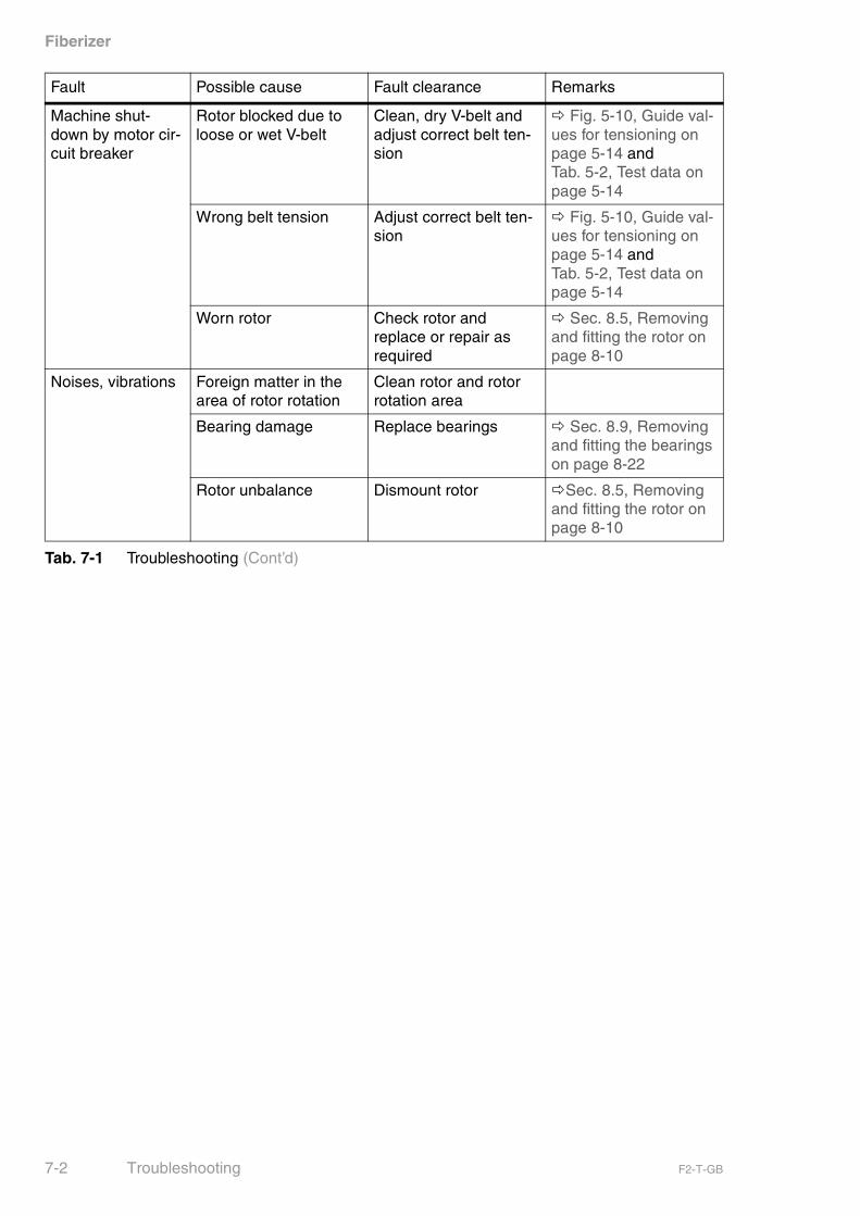
Machine shut-down by motor cir-cuit breaker
Rotor blocked due to loose or wet V-belt
Clean, dry V-belt and adjust correct belt ten-sion
� Fig. 5-10, Guide val-ues for tensioning on page 5-14 and Tab. 5-2, Test data on page 5-14
Wrong belt tension Adjust correct belt ten-sion
� Fig. 5-10, Guide val-ues for tensioning on page 5-14 and Tab. 5-2, Test data on page 5-14
Worn rotor Check rotor and replace or repair as required
� Sec. 8.5, Removing and fitting the rotor on page 8-10
Noises, vibrations Foreign matter in the area of rotor rotation
Clean rotor and rotor rotation area
Bearing damage Replace bearings � Sec. 8.9, Removing and fitting the bearings on page 8-22
Rotor unbalance Dismount rotor �Sec. 8.5, Removing and fitting the rotor on page 8-10
Fault Possible cause Fault clearance Remarks
Tab. 7-1 Troubleshooting (Cont’d)
7-2 Troubleshooting F2-T-GB
Fiberizer
Guards
Ensure that all required guards have been fitted again after comple-tion of all maintenance work.
Protection of persons
Ensure that the main switches of the machine and all upstream anddownstream machines are switched off and secured against uninten-tional restart prior to any maintenance work.
Make also sure that the machine and all stock pipes to the machinehave been emptied and depressurised.
Safe operation
To ensure safe operation after completion of maintenance and repairwork, use only new and undamaged fasteners (screws, bolts, wash-ers, locking elements, nuts, etc.) and new seals for reassembly.
8 Maintenance
8.1 Safety instructions for maintenance work
F2-T-GB Maintenance 8-1
Fiberizer
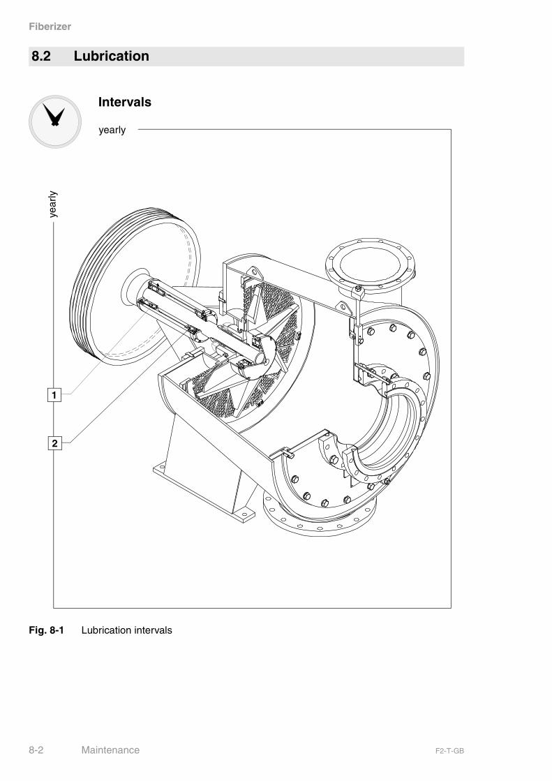
Fig. 8-1 Lubrication intervals
8.2 Lubrication
yearly
Intervals
year
ly
1
2
8-2 Maintenance F2-T-GB
Fiberizer
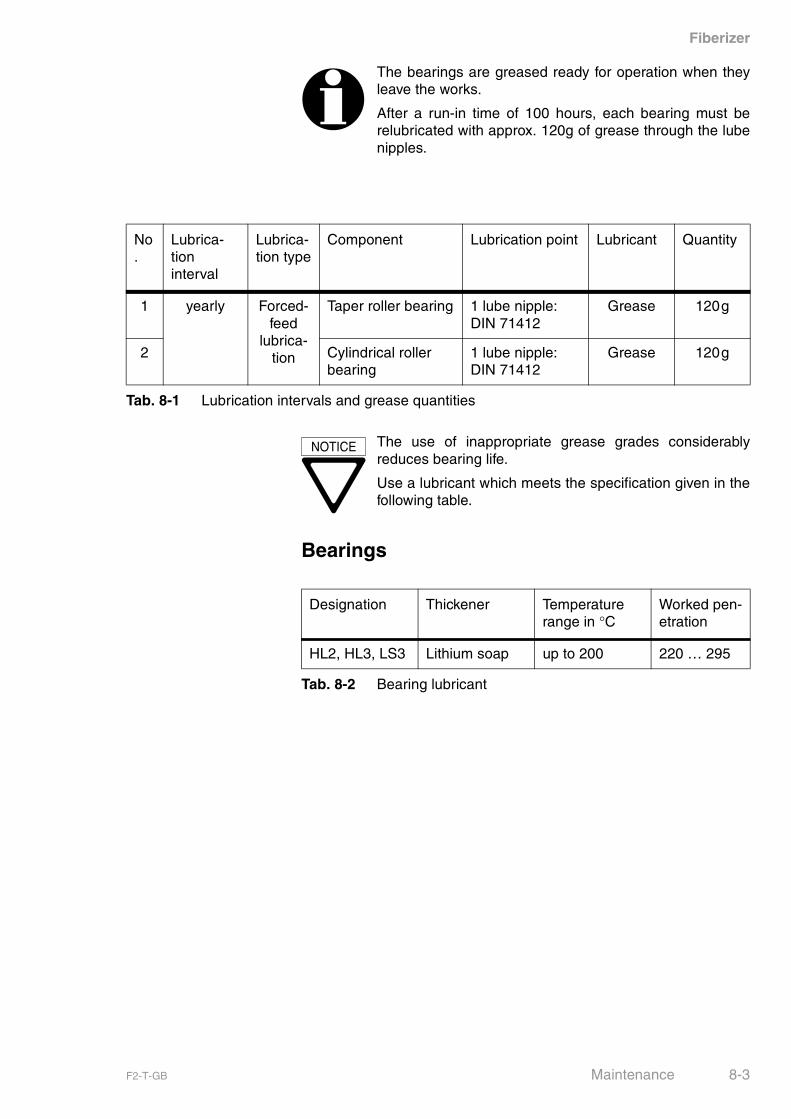
Bearings
The bearings are greased ready for operation when theyleave the works.
After a run-in time of 100 hours, each bearing must berelubricated with approx. 120g of grease through the lubenipples.
No.
Lubrica-tioninterval
Lubrica-tion type
Component Lubrication point Lubricant Quantity
1 yearly Forced- feed
lubrica-tion
Taper roller bearing 1 lube nipple:DIN 71412
Grease 120g
2 Cylindrical roller bearing
1 lube nipple:DIN 71412
Grease 120g
Tab. 8-1 Lubrication intervals and grease quantities
NOTICE The use of inappropriate grease grades considerablyreduces bearing life.
Use a lubricant which meets the specification given in thefollowing table.
Designation Thickener Temperature range in °C
Worked pen-etration
HL2, HL3, LS3 Lithium soap up to 200 220 … 295
Tab. 8-2 Bearing lubricant
F2-T-GB Maintenance 8-3
Fiberizer
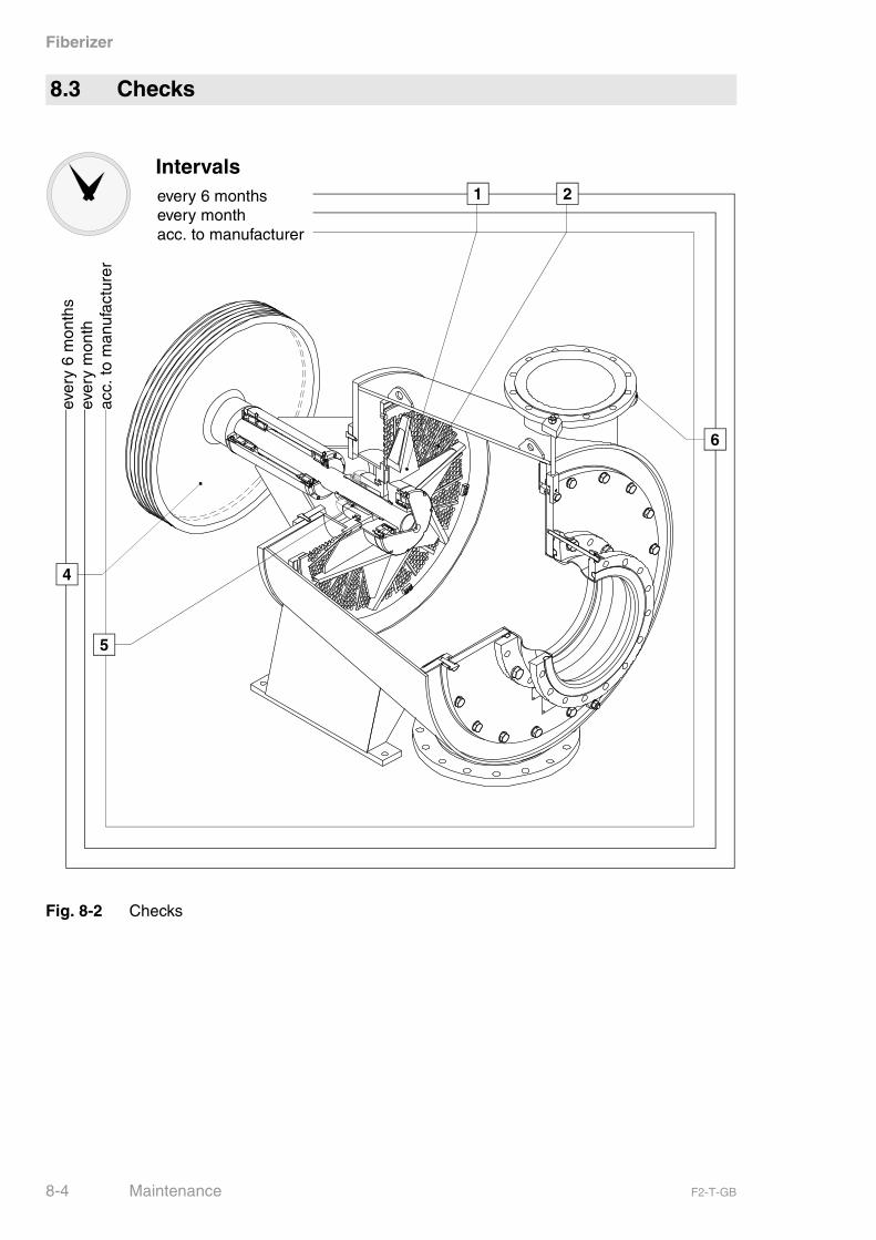
Fig. 8-2 Checks
8.3 Checks
Intervals21
4
5
6
every 6 monthsevery monthacc. to manufacturer
ever
y 6
mon
ths
ever
y m
onth
acc.
to m
anuf
actu
rer
8-4 Maintenance F2-T-GB

Fiberizer
General
The operating conditions determine the schedule for machine mainte-nance. Nevertheless, the rotor and the screen plate have to beinspected at least twice a year!
Preconditions
� Machine is flushed and drained (� Sec. 6.5, Shutdown onpage 6-5).
� Main switch is switched off and secured against unintentionalrestart.
No. Interval Compo-nent
Check Action Remark
1 Every 6 months
Rotor for damage and/or wear Remove and renew � Sec. 8.5, Removing and fitting the rotor on page 8-10
2 Screen plate
for damage and/or wear Remove and renew � Sec. 8.6, Removing and fitting the screen plate on page 8-14
3 Belts for cracks and/or wear Remove and renew � Sec. 5.10, Preparing for initial start-up on page 5-15
4 Belt pulley for damage and/or wear Remove and renew � Sec. 5.9, Mounting the belts on page 5-14
5 acc. to manufac-turer
Mechani-cal seal
acc. to manufacturer acc. to manufacturer � Sec. 12, Subcontrac-tor Docu-mentation
Tab. 8-3 Checks
F2-T-GB Maintenance 8-5

Fiberizer
6 Every month
Pressure gauge
contact-type pressure gauge for proper func-tioning and leakage
Remove contact-type pressure gauge.Check indicated values and switching values with appropriate testing equipment and adjust, if necessary. (see adjust-ment instructions in manufacturer’s docu-mentation), switching value: 2.5 bar rising.
Never remove con-tact-type pressure gauge with machine in operation or under pressure.
No. Interval Compo-nent
Check Action Remark
Tab. 8-3 Checks
8-6 Maintenance F2-T-GB

Fiberizer
Notes
F2-T-GB Maintenance 8-7
Fiberizer
Parts required
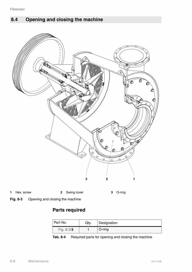
8.4 Opening and closing the machine
1 Hex. screw 2 Swing cover 3 O-ring
Fig. 8-3 Opening and closing the machine
123
Part No. Qty. Designation
Fig. 8-3/3 1 O-ring
Tab. 8-4 Required parts for opening and closing the machine
8-8 Maintenance F2-T-GB
Fiberizer
Preconditions
� Machine is drained and flushed (� Sec. 6.5, Shutdown onpage 6-5).
� Inlet, accepts and rejects valves are closed.
� No operating pressure indication on pressure gauges.
� Pump is switched off.
� Sealing water is switched off.
� Main switch is switched off and secured against unintentionalrestart.
� The connecting flange in the light rejects piping is disconnected atthe valve.
Opening the machine
� Slacken hex. screws (Fig. 8-3/1) on swing cover (Fig. 8-3/2).
� Pull off swing cover with jackoff screw and swing it out.
� Turn back jackoff screw.
� Open machine.
Closing the machine
� Insert new O-ring (Fig. 8-3/3) into casing groove.
� Swing cover in.
� Tighten hex. screws.
� Tightening torque 280 Nm with screw material A4-70.
� Mount inlet piping.
Check all connections and fittings for tightness while machine is stilldepressurised.
DANGER
Always tighten all cover screws.
If this is not done, the cover might work loose and getthrown off due to the pressure within the machine.
This can cause serious injuries.
F2-T-GB Maintenance 8-9
Fiberizer
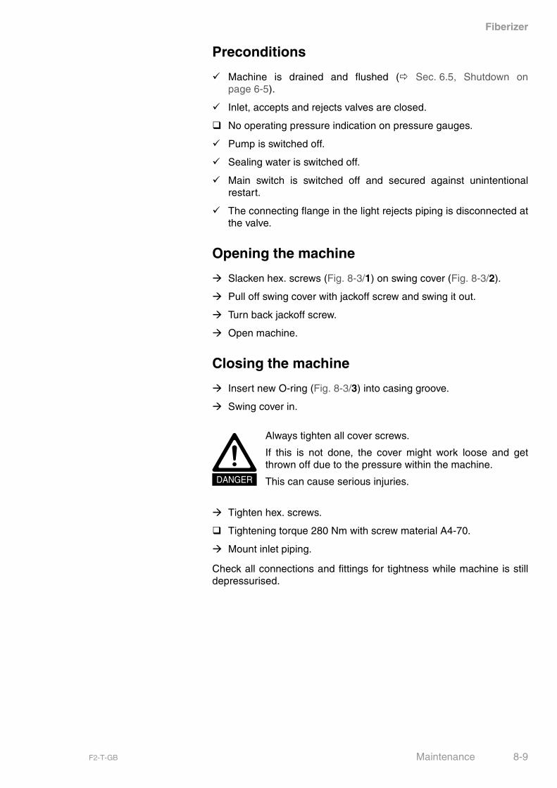
8.5 Removing and fitting the rotor
1 Rotor 3 Locking screw 5 Cover
2 Shrink disc 4 Socket head cap screw 6 O-ring
Fig. 8-4 Loosen rotor fastening
4
2 3
56
1
8-10 Maintenance F2-T-GB

Fiberizer
Preconditions
� Inlet valve is closed.
� Machine is drained and flushed (� Sec. 6.5, Shutdown onpage 6-5).
� Main switch is switched off and secured against unintentionalrestart.
� The inlet pipe between pulper and machine is dismount.
� Machine is open (� Sec. 8.4, Opening and closing the machineon page 8-8).
Materials required
Special tools and equipment
Parts required
Loosen rotor fastening
� Loosen socket head cap screws (Fig. 8-4/4) and remove cover(Fig. 8-4/5).
� Evenly and successively loosen locking screws (Fig. 8-4/3) on theshrink disc (Fig. 8-4/2) by several turns.
� Remove shrink disc (Fig. 8-4/2) from rotor hub.
Materials required Use
Grease for filling the hollow rotor space
Tab. 8-5 Materials required for removing and fitting the rotor
Special tools Usage
Mounting device Rotor removal
Tab. 8-6 Special tools and equipment for removing and fitting therotor
Part No. Qty. Designation
Fig. 8-4/1 1 Rotor
Fig. 8-4/2 1 Shrink disc
Fig. 8-4/4 8 Socket head cap screw
Fig. 8-4/6 1 O-ring
for Fig. 8-4/1 1 O-ring
Tab. 8-7 Required parts for removing and fitting the rotor
F2-T-GB Maintenance 8-11
Fiberizer
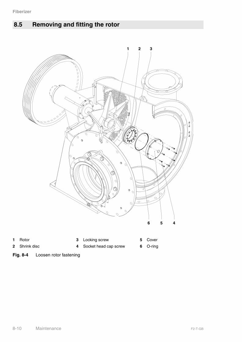
1 Screen plate ribs 3 U-clamp 5 Rotor
2 Mounting device 4 Centre screw
Fig. 8-5 Removing and fitting the rotor
1
3
6
2
45
8-12 Maintenance F2-T-GB
Fiberizer
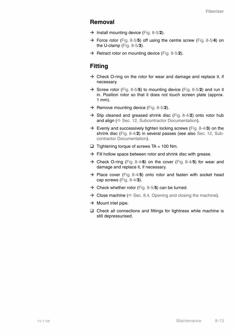
Removal
� Install mounting device (Fig. 8-5/2).
� Force rotor (Fig. 8-5/5) off using the centre screw (Fig. 8-5/4) onthe U-clamp (Fig. 8-5/3).
� Retract rotor on mounting device (Fig. 8-5/2).
Fitting
� Check O-ring on the rotor for wear and damage and replace it, ifnecessary.
� Screw rotor (Fig. 8-5/5) to mounting device (Fig. 8-5/2) and run itin. Position rotor so that it does not touch screen plate (approx.1 mm).
� Remove mounting device (Fig. 8-5/2).
� Slip cleaned and greased shrink disc (Fig. 8-4/2) onto rotor huband align (� Sec. 12, Subcontractor Documentation).
� Evenly and successively tighten locking screws (Fig. 8-4/3) on theshrink disc (Fig. 8-4/2) in several passes (see also Sec. 12, Sub-contractor Documentation).
� Tightening torque of screws TA = 100 Nm.
� Fill hollow space between rotor and shrink disc with grease.
� Check O-ring (Fig. 8-4/6) on the cover (Fig. 8-4/5) for wear anddamage and replace it, if necessary.
� Place cover (Fig. 8-4/5) onto rotor and fasten with socket headcap screws (Fig. 8-4/3).
� Check whether rotor (Fig. 8-5/5) can be turned.
� Close machine (� Sec. 8.4, Opening and closing the machine).
� Mount inlet pipe.
� Check all connections and fittings for tightness while machine isstill depressurised.
F2-T-GB Maintenance 8-13
Fiberizer
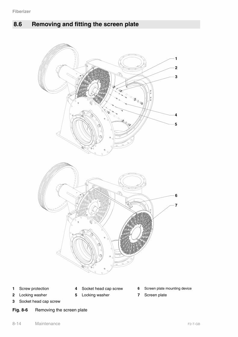
8.6 Removing and fitting the screen plate
1 Screw protection 4 Socket head cap screw 6 Screen plate mounting device
2 Locking washer 5 Locking washer 7 Screen plate
3 Socket head cap screw
Fig. 8-6 Removing the screen plate
1
2
6
7
3
4
5
8-14 Maintenance F2-T-GB
Fiberizer
Preconditions
� Inlet valve is closed.
� Machine is drained and flushed (� Sec. 6.5, Shutdown onpage 6-5).
� Main switch is switched off and secured against unintentionalrestart.
� The inlet pipe between pulper and machine is dismount.
� Machine is open (� Sec. 8.4, Opening and closing the machineon page 8-8).
� Rotor is removed (� Sec. 8.5, Removing and fitting the rotor onpage 8-10)
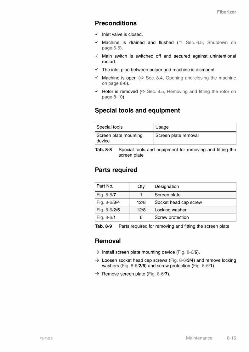
Special tools and equipment
Parts required
Removal
� Install screen plate mounting device (Fig. 8-6/6).
� Loosen socket head cap screws (Fig. 8-6/3/4) and remove lockingwashers (Fig. 8-6/2/5) and screw protection (Fig. 8-6/1).
� Remove screen plate (Fig. 8-6/7).
Special tools Usage
Screen plate mounting device
Screen plate removal
Tab. 8-8 Special tools and equipment for removing and fitting thescreen plate
Part No. Qty Designation
Fig. 8-6/7 1 Screen plate
Fig. 8-6/3/4 12/8 Socket head cap screw
Fig. 8-6/2/5 12/8 Locking washer
Fig. 8-6/1 6 Screw protection
Tab. 8-9 Parts required for removing and fitting the screen plate
F2-T-GB Maintenance 8-15

Fiberizer
1 Screw protection 4 Socket head cap screw 6 Screen plate mounting device
2 Locking washer 5 Locking washer 7 Screen plate
3 Socket head cap screw
Fig. 8-7 Fitting the screen plate
1
2
6
7
3
4
5
8-16 Maintenance F2-T-GB

Fiberizer
Fitting
� Hang new screen plate (Fig. 8-7/7) into screen plate mountingdevice (Fig. 8-7/6).
� Mount screen plate with socket head cap screws (Fig. 8-7/3/4),locking washers (Fig. 8-7/2/5) and screw protection (Fig. 8-7/3).
� Remove screen plate mounting device (Fig. 8-7/6).
� Fit rotor (� Sec. 8.5, Removing and fitting the rotor on page 8-10).
� Close machine (� Sec. 8.4, Opening and closing the machine onpage 8-8).
� Mount inlet pipe.
� Check all connections and fittings for tightness while machine isstill depressurised.
F2-T-GB Maintenance 8-17

Fiberizer
8.7 Removing and fitting the mechanical seal
1 Mechanical seal
Fig. 8-8 Removing and fitting the mechanical seal
1
8-18 Maintenance F2-T-GB
Fiberizer
Preconditions
� Inlet valve is closed.
� Machine is drained and flushed (� Sec. 6.5, Shutdown onpage 6-5).
� Main switch is switched off and secured against unintentionalrestart.
� Sealing-water supply line is closed.
Removal
� Remove mechanical seal (Fig. 8-8/1) as described in AESSEALdocumentation (� Sec. 12, Subcontractor Documentation).
Fitting
� Install mechanical seal (Fig. 8-8/1) as described in AESSEAL doc-umentation (� Sec. 12, Subcontractor Documentation).
F2-T-GB Maintenance 8-19
Fiberizer
Parts required
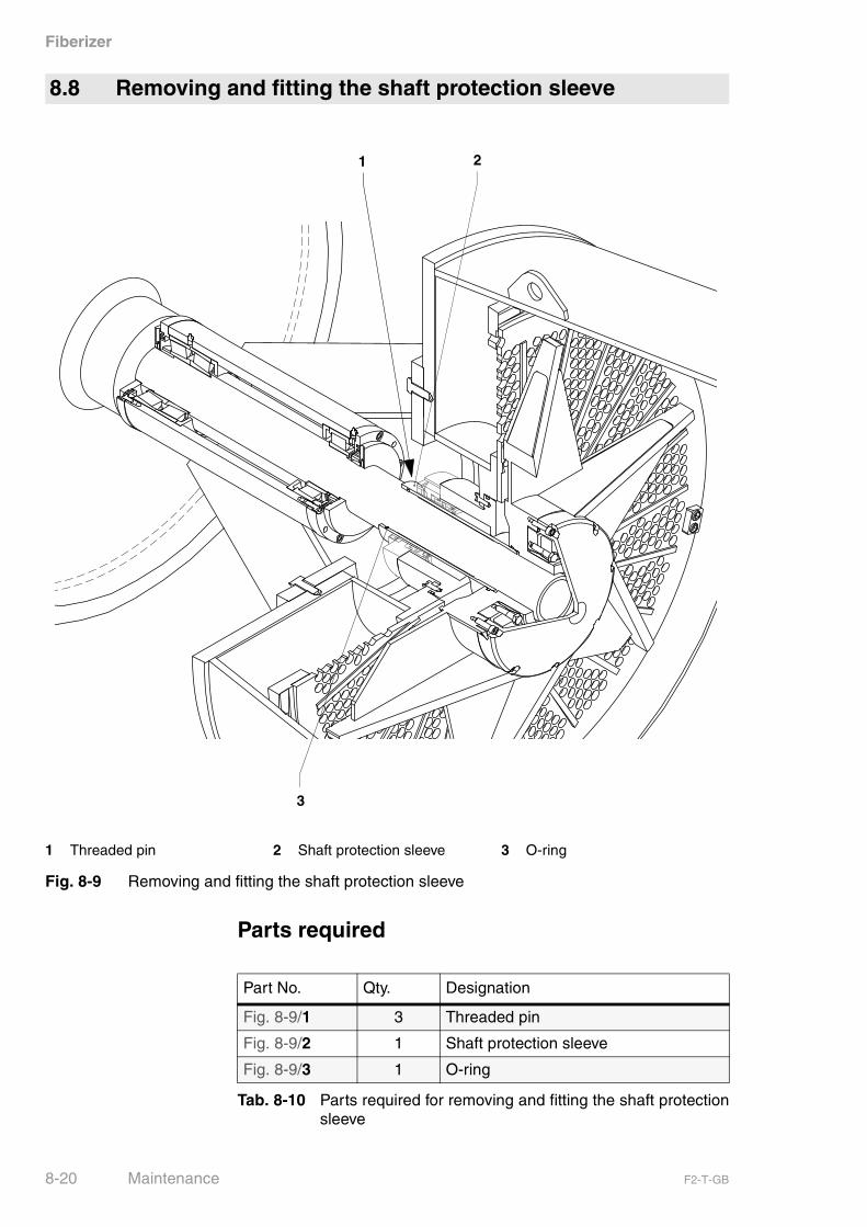
8.8 Removing and fitting the shaft protection sleeve
1 Threaded pin 2 Shaft protection sleeve 3 O-ring
Fig. 8-9 Removing and fitting the shaft protection sleeve
1
3
2
Part No. Qty. Designation
Fig. 8-9/1 3 Threaded pin
Fig. 8-9/2 1 Shaft protection sleeve
Fig. 8-9/3 1 O-ring
Tab. 8-10 Parts required for removing and fitting the shaft protectionsleeve
8-20 Maintenance F2-T-GB
Fiberizer
Preconditions
� Inlet valve is closed.
� Machine is drained and flushed (� Sec. 6.5, Shutdown onpage 6-5).
� Main switch is switched off and secured against unintentionalrestart.
� Sealing-water supply line is closed.
� Rotor is removed (� Sec. 8.5, Removing and fitting the rotor onpage 8-10).
� Mechanical seal is removed (� Sec. 8.7, Removing and fitting themechanical seal on page 8-18).
Removal
� Loosen all three threaded pins (Fig. 8-9/1) and remove shaft pro-tection sleeve (Fig. 8-9/2) from shaft.
Fitting
� Thoroughly clean shaft.
� Install new shaft protection sleeve (Fig. 8-9/2) with new O-ring(Fig. 8-9/3) on the shaft.
� Use new threaded pins (Fig. 8-9/1) to fasten shaft protectionsleeve (Fig. 8-9/2) to the shaft.
� Install mechanical seal (� Sec. 8.7, Removing and fitting themechanical seal on page 8-18).
� Install rotor (� Sec. 8.5, Removing and fitting the rotor onpage 8-10).
� Close machine (� Sec. 8.4, Opening and closing the machine onpage 8-8).
� Mount inlet pipe.
� Check all connections and fittings for tightness while machine isstill depressurised.
NOTICE Handle ceramic protection sleeve with care. Risk of fracture!
F2-T-GB Maintenance 8-21
Fiberizer
Parts required
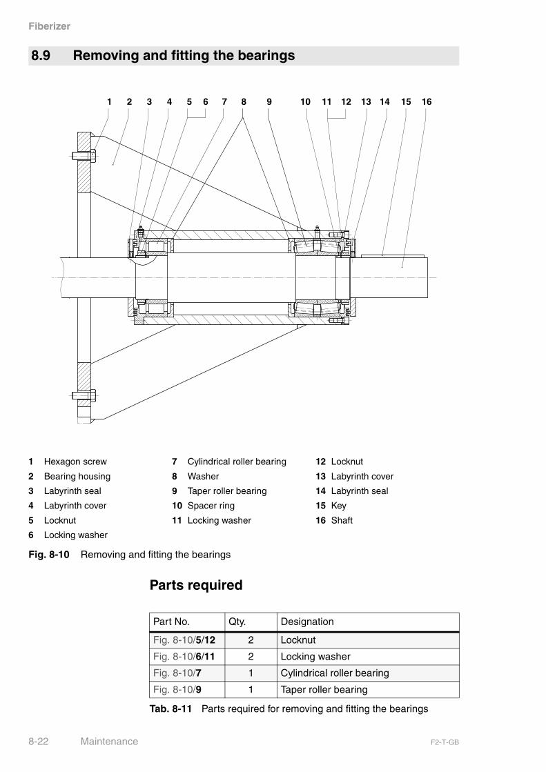
8.9 Removing and fitting the bearings
1 Hexagon screw 7 Cylindrical roller bearing 12 Locknut
2 Bearing housing 8 Washer 13 Labyrinth cover
3 Labyrinth seal 9 Taper roller bearing 14 Labyrinth seal
4 Labyrinth cover 10 Spacer ring 15 Key
5 Locknut 11 Locking washer 16 Shaft
6 Locking washer
Fig. 8-10 Removing and fitting the bearings
1 2 5 63 4 7 8 12 139 14 151110 16
Part No. Qty. Designation
Fig. 8-10/5/12 2 Locknut
Fig. 8-10/6/11 2 Locking washer
Fig. 8-10/7 1 Cylindrical roller bearing
Fig. 8-10/9 1 Taper roller bearing
Tab. 8-11 Parts required for removing and fitting the bearings
8-22 Maintenance F2-T-GB
Fiberizer
Preconditions
� Inlet valve is closed.
� Machine is drained and flushed (� Sec. 6.5, Shutdown onpage 6-5).
� Main switch is switched off and secured against unintentionalrestart.
� The inlet pipe between pulper and machine is dismount.
� Machine is open (� Sec. 8.4, Opening and closing the machineon page 8-8).
� Rotor is removed (� Sec. 8.5, Removing and fitting the rotor onpage 8-10)
� Mechanical seal is removed (� Sec. 8.7, Removing and fitting themechanical seal on page 8-18).
� Shaft protection sleeve is removed (� Sec. 8.8, Removing and fit-ting the shaft protection sleeve on page 8-20).
Preparations
� Remove belt guard.
� Remove belts.
� Remove belt pulley from shaft (Fig. 8-10/2) (� Sec. 5.8, Mountingand dismounting the belt pulleys on page 5-12).
Removal
� Loosen hexagon screws (Fig. 8-10/1) and remove the bearinghousing (Fig. 8-10/2) from the rotor casing.
� Remove key (Fig. 8-10/15) from shaft.
� Remove labyrinth cover (Fig. 8-10/5) and labyrinth rings(Fig. 8-10/1).
� Loosen and remove locknut (Fig. 8-10/5/12) and locking washer(Fig. 8-10/6/11).
� Remove taper roller bearing (Fig. 8-10/9).
� Pull shaft with cylindrical roller bearings (Fig. 8-10/7) out of thebearing housing from the rotor side.
� Remove cylindrical roller bearing (Fig. 8-10/9) from shaft.
DANGER
Use only appropriate lifting equipment for transporting thebelt pulley and the bearing housing. Always stand at a safe distance from suspended loads.
F2-T-GB Maintenance 8-23

Fiberizer
Fitting
Reverse removal sequence when fitting the bearings.
� Thoroughly clean the shaft and all reusable parts.
� Grease the shaft.
� Use a feeler gauge to measure the size of the radial play of thenew cylindrical roller bearing (Fig. 8-10/7).
� Install shaft protection sleeve (� Sec. 8.8, Removing and fittingthe shaft protection sleeve on page 8-20).
� Install mechanical seal (� Sec. 8.7, Removing and fitting themechanical seal on page 8-18).
� Install rotor (� Sec. 8.5, Removing and fitting the rotor onpage 8-10).
� Close machine (� Sec. 8.4, Opening and closing the machine onpage 8-8).
� Mount inlet pipe.
� Check all connections and fittings for tightness while machine isstill depressurised.
8-24 Maintenance F2-T-GB

Fiberizer
Applying the hard surfacing
� Completely remove the remaining hard surfacing.
� Manually apply the hard surfacing.
� Let the hard surfacing cool down slowly.
Recommended welding electrodes
VAUTID-K
Fig. 8-11 Rotor hard surfacing
8.10 Repairing the wearing parts
To obtain the optimum rotor wear protection, it should becoated with CrNiBSi+Wc.
This CrNiBSi+Wc coating can be applied by Voith Sulzer.
F2-T-GB Maintenance 8-25

Fiberizer
8-26 Maintenance F2-T-GB
Fiberizer
9 Spare Parts
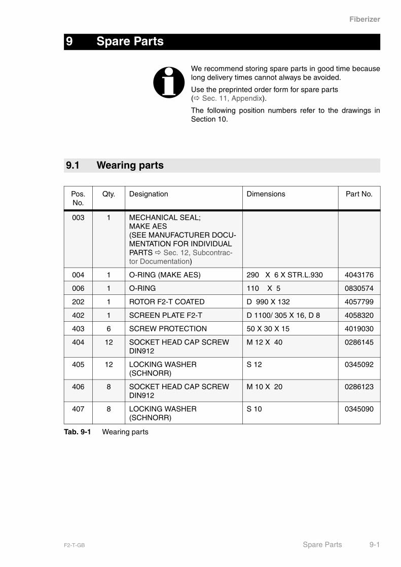
We recommend storing spare parts in good time becauselong delivery times cannot always be avoided.
Use the preprinted order form for spare parts(� Sec. 11, Appendix).
The following position numbers refer to the drawings inSection 10.
9.1 Wearing parts
Pos. No.
Qty. Designation Dimensions Part No.
003 1 MECHANICAL SEAL; MAKE AES(SEE MANUFACTURER DOCU-MENTATION FOR INDIVIDUAL PARTS � Sec. 12, Subcontrac-tor Documentation)
004 1 O-RING (MAKE AES) 290 X 6 X STR.L.930 4043176
006 1 O-RING 110 X 5 0830574
202 1 ROTOR F2-T COATED D 990 X 132 4057799
402 1 SCREEN PLATE F2-T D 1100/ 305 X 16, D 8 4058320
403 6 SCREW PROTECTION 50 X 30 X 15 4019030
404 12 SOCKET HEAD CAP SCREW DIN912
M 12 X 40 0286145
405 12 LOCKING WASHER (SCHNORR)
S 12 0345092
406 8 SOCKET HEAD CAP SCREW DIN912
M 10 X 20 0286123
407 8 LOCKING WASHER (SCHNORR)
S 10 0345090
Tab. 9-1 Wearing parts
F2-T-GB Spare Parts 9-1

Fiberizer
9.2 Replacement parts
Pos. No.
Qty. Designation Dimensions Part No.
002 1 HOUSING (FA.AES) D 300 X 175 4063038
005 1 SHAFT PROTECTION SLEEVE D 125/110 X 295 FS3/4B 4632238
007 3 THREADED PIN DIN914 M 6 X 10 0269410
008 6 SOCKET HEAD CAP SCREW ISO4762
M 12 X 30 0286143
009 12 WASHER DIN125-1 B 13 0331021
106 1 TAPER ROLLER BEARING 32224 120/215 X 123 4018454
107 2 LOCKING WASHER DIN5406 MBL24 4019787
108 2 LOCK NUT DIN981 KML24 M 120 X 2 4019788
109 1 CYLINDRICAL ROLLER BEAR-ING
NU 2224 E 120/215 X 58 4018453
203 1 COVER D 328 X 107 4040811
204 8 SOCKET HEAD CAP SCREW ISO4762
M 10 X 40 0286127
205 1 O-RING 275 X 4 X STR. L.876 0540004
206 1 O-RING 125 X 5 4612045
207 1 SHRINK DISC 155 RFN 4071 4026081
304 1 O-RING 1196 X 10 X STR. L.3788 0540010
319 1 V-SEAL D 45/55 X 9 4015609
329 1 SEAL RING D 300/240 X 2 4019132
332 1 RUBBER COMPENSATOR TYPE A-2 PN10 DN300 4014884
904 8 V-BELT SPC LW 5600 4014906
Tab. 9-2 Replacement parts
9-2 Spare Parts F2-T-GB
Fiberizer
10 Main Parts List
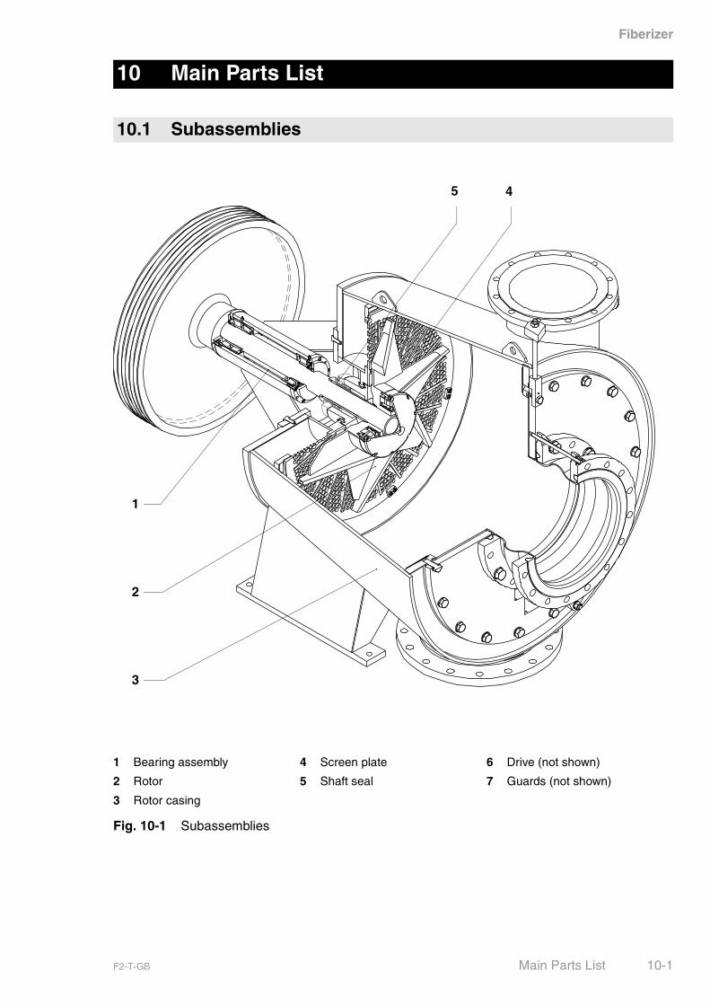
10.1 Subassemblies
1 Bearing assembly 4 Screen plate 6 Drive (not shown)
2 Rotor 5 Shaft seal 7 Guards (not shown)
3 Rotor casing
Fig. 10-1 Subassemblies
1
2
3
45
F2-T-GB Main Parts List 10-1
Fiberizer
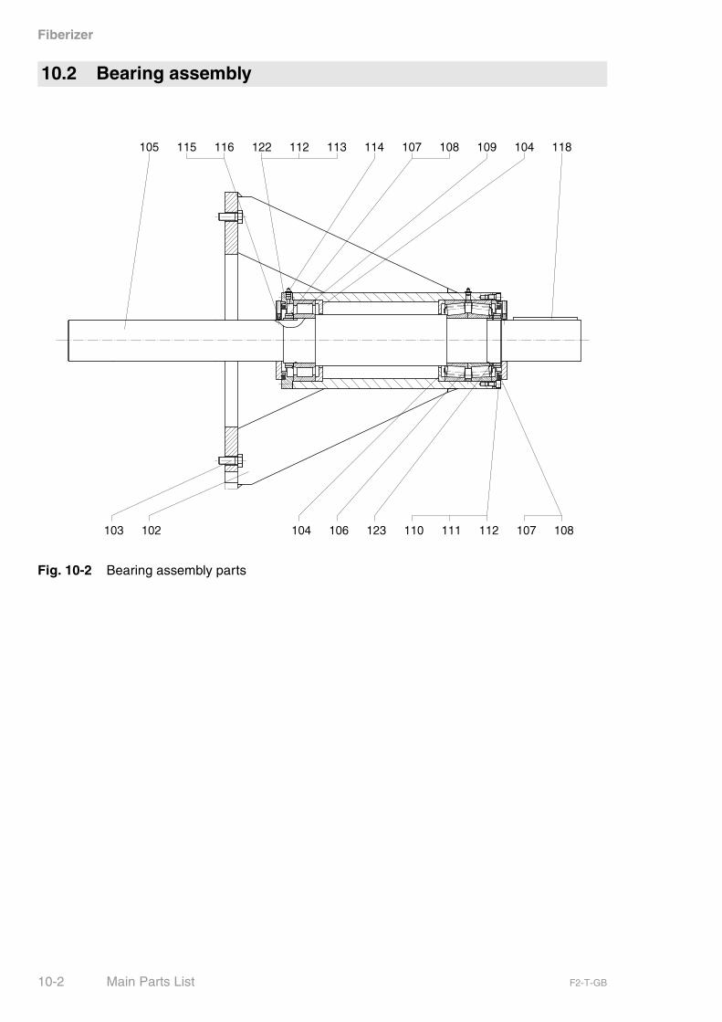
Fig. 10-2 Bearing assembly parts
10.2 Bearing assembly
10-2 Main Parts List F2-T-GB
Fiberizer
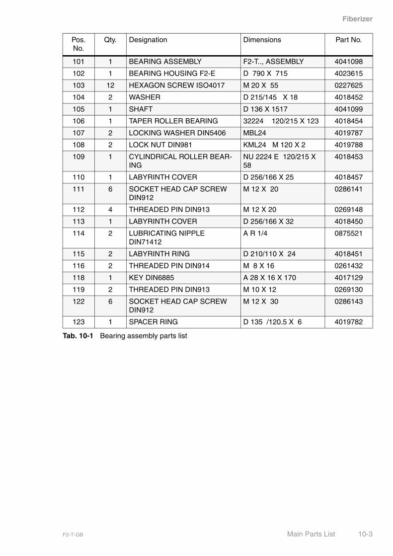
Pos. No.
Qty. Designation Dimensions Part No.
101 1 BEARING ASSEMBLY F2-T.., ASSEMBLY 4041098
102 1 BEARING HOUSING F2-E D 790 X 715 4023615
103 12 HEXAGON SCREW ISO4017 M 20 X 55 0227625
104 2 WASHER D 215/145 X 18 4018452
105 1 SHAFT D 136 X 1517 4041099
106 1 TAPER ROLLER BEARING 32224 120/215 X 123 4018454
107 2 LOCKING WASHER DIN5406 MBL24 4019787
108 2 LOCK NUT DIN981 KML24 M 120 X 2 4019788
109 1 CYLINDRICAL ROLLER BEAR-ING
NU 2224 E 120/215 X 58
4018453
110 1 LABYRINTH COVER D 256/166 X 25 4018457
111 6 SOCKET HEAD CAP SCREW DIN912
M 12 X 20 0286141
112 4 THREADED PIN DIN913 M 12 X 20 0269148
113 1 LABYRINTH COVER D 256/166 X 32 4018450
114 2 LUBRICATING NIPPLE DIN71412
A R 1/4 0875521
115 2 LABYRINTH RING D 210/110 X 24 4018451
116 2 THREADED PIN DIN914 M 8 X 16 0261432
118 1 KEY DIN6885 A 28 X 16 X 170 4017129
119 2 THREADED PIN DIN913 M 10 X 12 0269130
122 6 SOCKET HEAD CAP SCREW DIN912
M 12 X 30 0286143
123 1 SPACER RING D 135 /120.5 X 6 4019782
Tab. 10-1 Bearing assembly parts list
F2-T-GB Main Parts List 10-3
Fiberizer
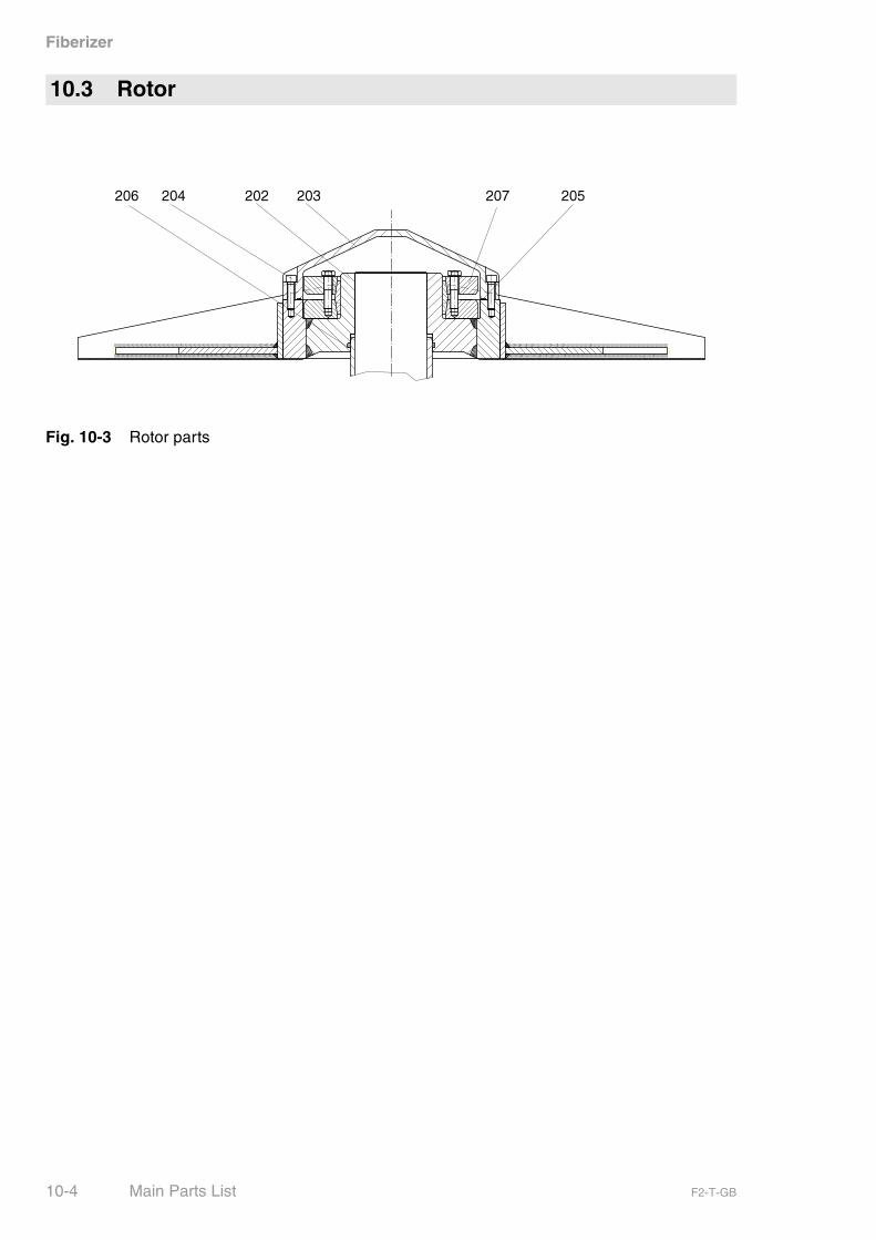
Fig. 10-3 Rotor parts
10.3 Rotor
10-4 Main Parts List F2-T-GB

Fiberizer
Pos. No.
Qty. Designation Dimensions Part No.
- 1 ROTOR (SHRINK DISC) F2-T, ASSEMBLY 4041075
202 1 ROTOR F2-T COATED D 990 X 132 4057799
203 1 COVER D 328 X 107 4040811
204 8 SOCKET HEAD CAP SCREW ISO4762
M 10 X 40 0286127
205 1 O-RING 275 X 4 X STR. L.876 0540004
206 1 O-RING 125 X 5 4612045
207 1 SHRINK DISC 155 RFN 4071 4026081
Tab. 10-2 Rotor parts list
F2-T-GB Main Parts List 10-5
Fiberizer
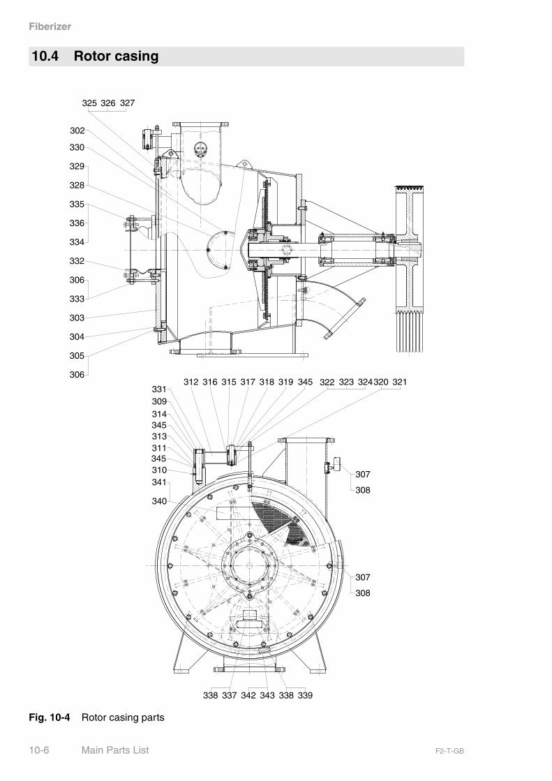
Fig. 10-4 Rotor casing parts
10.4 Rotor casing
10-6 Main Parts List F2-T-GB

Fiberizer
Pos. No.
Qty. Designation Dimensions Part No.
301 1 ROTOR CASING F2-T, ASSEMBLY 4063085
302 1 ROTOR CASING F2-T 1675 X 1492 X 1192 4040237
303 1 COVER F2-T DN300 D 1300/300 X 83 4046544
304 1 O-RING 1196 X 10 X STR. L.3788
0540010
305 18 HEXAGON SCREW DIN931 M 20 X 70 0221417
306 30 WASHER DIN125 21 0331024
307 2 PRESSURE GAUGE D 100, 0- 6 BAR 0501110
308 12 HEXAGON SCREW DIN933 M 6 X 16 0227424
309 1 BOLT D 50 X 250 4018773
310 1 THREADED PIN DIN913 M 10 X 20 0269134
311 1 SPACER RING D 58/50.5 X 4 4018772
312 1 LEVER 434.4 X 141 X 88.9 4018878
313 1 NEEDLE ANGULAR-CONTACT BALL BEARING
NJA 5910 D 50/72 X 30 4018770
314 1 NEEDLE ROLLER BEARING NA4909.2RS D 45/68 X 23
4018769
315 1 NEEDLE ANGULAR-CONTACT BALL BEARING
NJA 5908 D 40/62 X 30 4018778
316 1 NEEDLE ROLLER BEARING NKJ40/20A D 40/55 X 20
4018777
317 1 HINGE PIN 240 X 151 X 80 4019526
318 1 SPACER RING D 50/40.5 X 8 4019528
319 1 V-SEAL D 45/55 X 9 4015609
320 1 WASHER D 45 X 5 4018781
321 1 HEXAGON SCREW DIN933 M 8 X 16 0227451
322 1 THREADED ROD D 16 X 300 4019529
323 3 HEXAGON NUT DIN934 M 16 0311016
324 3 WASHER DIN125 17 0331022
325 1 HOLDER 30 X 30 X 120 4018774
326 1 HEXAGON SCREW DIN933 M 16 X 30 0227563
327 1 SPRING-TYPE STRAIGHT PIN DIN1481
6 X 30 0377230
328 1 COVER D 300 X 48 4047337
329 1 SEAL RING D 300/240 X 2 4019132
330 4 STUD BOLT DIN939 M 12 X 45 0256356
331 1 CIRCLIP DIN472 68 X 2.5 4024925
332 1 RUBBER COMPENSATOR TYPE A-2 PN10 DN300 4014884
333 12 HEXAGON SCREW DIN933 M 20 X 60 0227626
Tab. 10-3 Rotor casing parts list
F2-T-GB Main Parts List 10-7
Fiberizer
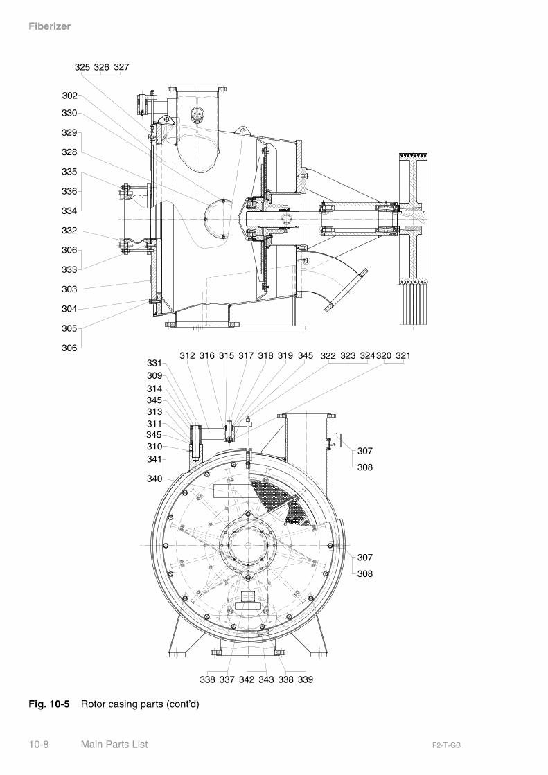
Fig. 10-5 Rotor casing parts (cont’d)
10-8 Main Parts List F2-T-GB
Fiberizer
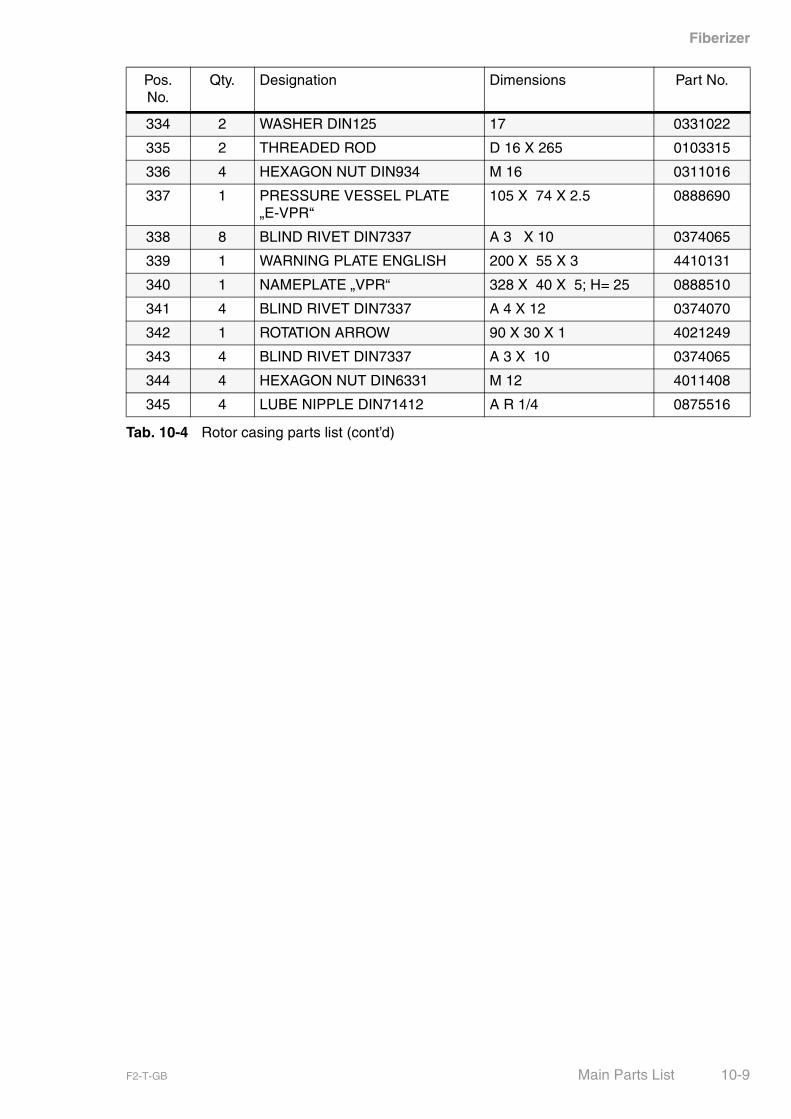
Pos. No.
Qty. Designation Dimensions Part No.
334 2 WASHER DIN125 17 0331022
335 2 THREADED ROD D 16 X 265 0103315
336 4 HEXAGON NUT DIN934 M 16 0311016
337 1 PRESSURE VESSEL PLATE „E-VPR“
105 X 74 X 2.5 0888690
338 8 BLIND RIVET DIN7337 A 3 X 10 0374065
339 1 WARNING PLATE ENGLISH 200 X 55 X 3 4410131
340 1 NAMEPLATE „VPR“ 328 X 40 X 5; H= 25 0888510
341 4 BLIND RIVET DIN7337 A 4 X 12 0374070
342 1 ROTATION ARROW 90 X 30 X 1 4021249
343 4 BLIND RIVET DIN7337 A 3 X 10 0374065
344 4 HEXAGON NUT DIN6331 M 12 4011408
345 4 LUBE NIPPLE DIN71412 A R 1/4 0875516
Tab. 10-4 Rotor casing parts list (cont’d)
F2-T-GB Main Parts List 10-9

Fiberizer
Fig. 10-6 Screen plate parts
10.5 Screen plate
10-10 Main Parts List F2-T-GB

Fiberizer
Pos. No.
Qty. Designation Dimensions Part No.
401 1 SCREEN PLATE F2-T, ASSEMBLY 4058335
402 1 SCREEN PLATE F2-T D 1100/ 305 X 16, D 8 4058320
403 6 SCREW PROTECTION 50 X 30 X 15 4019030
404 12 SOCKET HEAD CAP SCREW DIN912
M 12 X 40 0286145
405 12 LOCKING WASHER (SCHNORR)
S 12 0345092
406 8 SOCKET HEAD CAP SCREW DIN912
M 10 X 20 0286123
407 8 LOCKING WASHER (SCHNORR)
S 10 0345090
Tab. 10-5 Screen plate parts list
F2-T-GB Main Parts List 10-11
Fiberizer
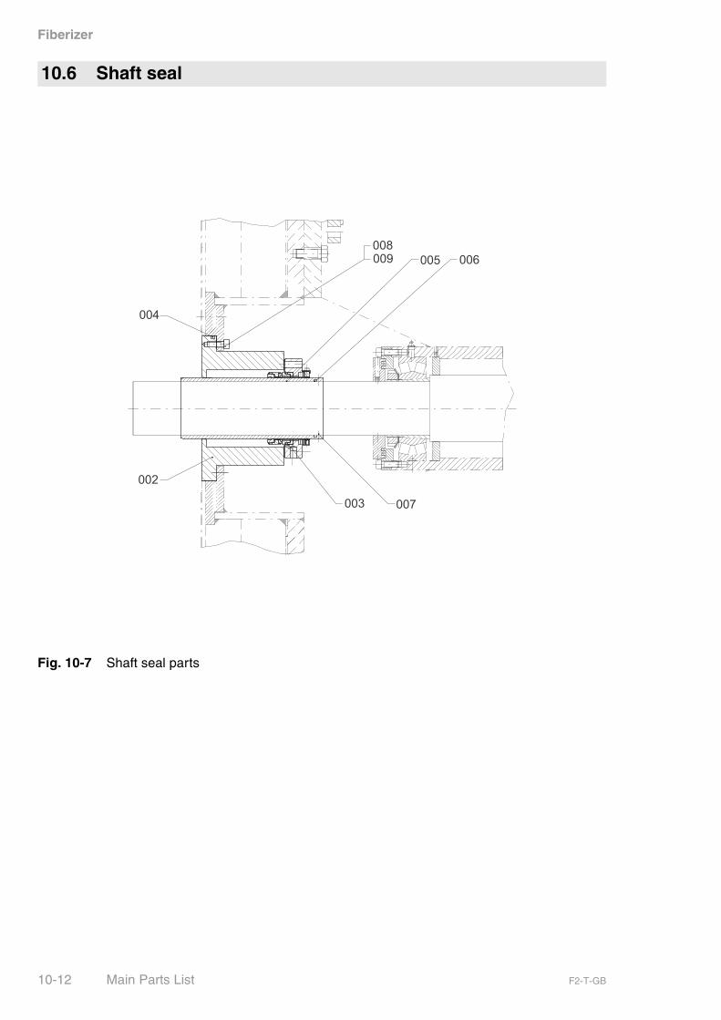
Fig. 10-7 Shaft seal parts
10.6 Shaft seal
10-12 Main Parts List F2-T-GB
Fiberizer
Pos. No.
Qty. Designation Dimensions Part No.
001 1 SHAFT SEAL F2-T.S,(W/O SEALING WATER)
4063037
002 1 HOUSING (MAKE AES) D 300 X 175 4063038
003 1 MECHANICAL SEAL ;MAKE AES 198.7/125 X 50 4063039
004 1 O-RING (MAKE AES) 290 X 6 X STR. L.930 4043176
005 1 SHAFT PROTECTION SLEEVE D 125/110 X 295 FS3/4B
4632238
006 1 O-RING 110 X 5 0830574
007 3 THREADED PIN DIN914 M 6 X 10 0269410
008 6 SOCKET HEAD CAP SCREW ISO4762
M 12 X 30 0286143
009 12 WASHER DIN125-1 B 13 0331021
Tab. 10-6 Shaft seal parts list
F2-T-GB Main Parts List 10-13
Fiberizer
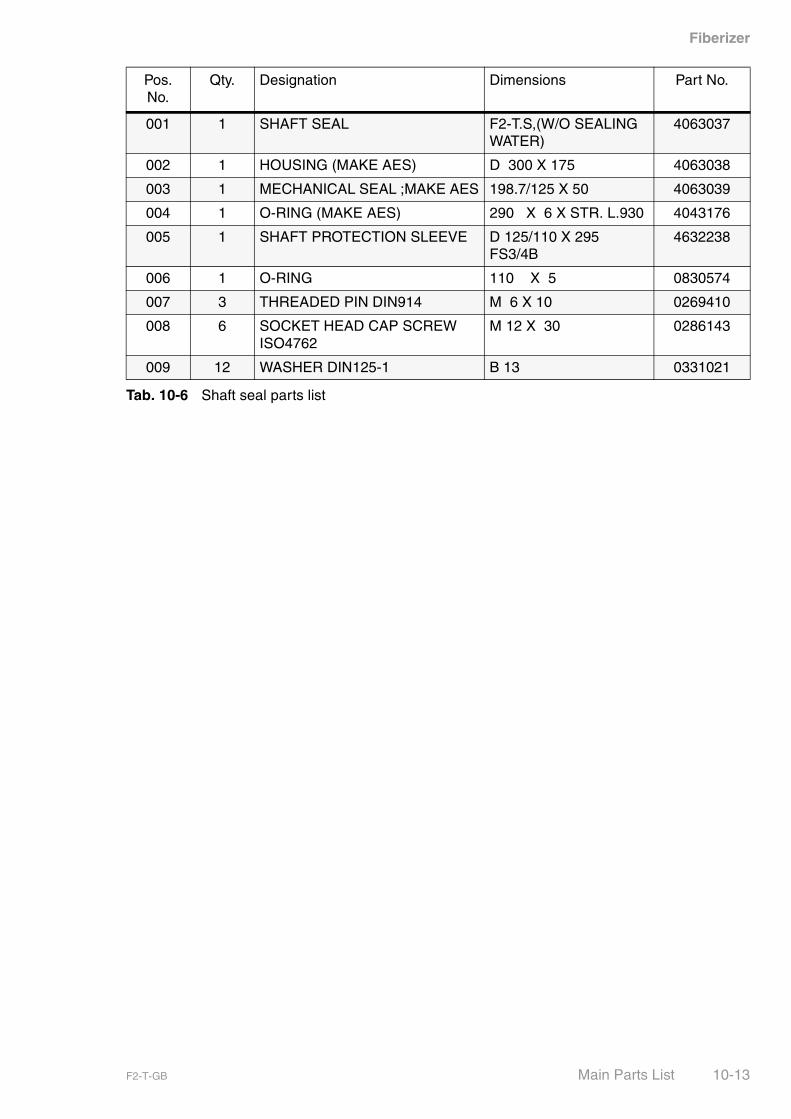
Fig. 10-8 Drive parts
10.7 Drive
10-14 Main Parts List F2-T-GB

Fiberizer
Pos. No.
Qty. Designation Dimensions Part No.
901 1 DRIVE V-BELT F2-T, N=1480 RPM, 200KW
4063082
902 1 V-BELT PULLEY SPC IINCL. TAPER-LOCK CLAMPING BUSH
DW 1120 X 355 8 GROOVES
4021383
903 1 V-BELT PULLEY SPC INCL. TAPER-LOCK CLAMPING BUSH
DW 315 X 212.5 8 GROOVES
4021384
904 8 V-BELT SPC LW 5600 4014906
Tab. 10-7 Drive parts list
F2-T-GB Main Parts List 10-15

Fiberizer
Fig. 10-9 Guard parts
10.8 Guard
10-16 Main Parts List F2-T-GB

Fiberizer
Pos. No.
Qty. Designation Dimensions Part No.
001 1 GUARD F2-T/E/TE, ASSY. 4019197
009 5 HEXAGON SCREW DIN933 M 12 X 20 0227511
010 5 ANCHOR M 12 0212212
011 5 WASHER DIN125-1 B 13 0330012
Tab. 10-8 Guard parts list
F2-T-GB Main Parts List 10-17
Fiberizer
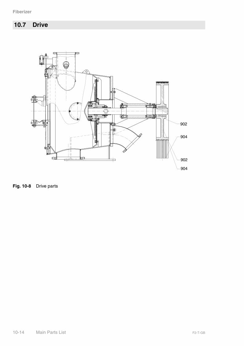
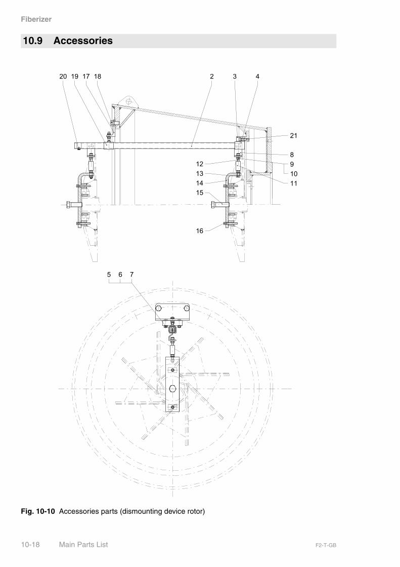
Fig. 10-10 Accessories parts (dismounting device rotor)
10.9 Accessories
10-18 Main Parts List F2-T-GB

Fiberizer
Pos. No.
Qty. Designation Dimensions Part No.
001 1 DISMOUNTING DEVICE F2-T., ASSY. 4040364
002 1 SLIDE RAIL SYSTEM HELM PROFILE NO.300,LG 1020
4019001
003 1 FLAT STEEL 50 X 30 X 115 0114272
004 1 FASTENING SLEEVE SLEEVE NO.302 SYST.HELM
4612244
005 2 HEXAGON SCREW DIN933 M 10 X 50 0225152
006 2 WASHER DIN125 10.5 0330010
007 2 HEXAGON NUT DIN934 M 10 0310110
008 1 ROLLING UNIT, SINGLE-PAIR NO. 390 SYST. HELM 4612246
009 3 HEXAGON NUT M 12 0310112
010 3 WASHER DIN125 13 0330012
011 1 TURNBUCKLE NUT SP M 12 4612248
012 1 STUD BOLT M 12 X 130 4019125
013 1 HEXAGON SCREW DIN933 M 12 X 80 0223207
014 1 ANGLE 410 X 120 X 80 4041035
015 1 HEXAGON SCREW DIN933 M 24 X 90 0227691
016 2 SOCKET HEAD CAP SCREW DIN912
M 10 X 80 0284165
017 1 ANGLE 100 X 50 X 10 X 100 4019127
018 1 HEXAGON SCREW DIN933 M 20 X 30 0225295
019 1 ADJUSTABLE SLEEVE NO. 304 SYST. HELM 4612249
020 1 RAIL LIMITS NO. 300 P SYST.HELM 4612250
021 1 SOCKET HEAD CAP SCREW DIN912
M 12 X 50 0284184
- 1 ANGLE 410 X 120 X 80 4041035
- 1 SCREEN CHANGING DEVICE F2-E/T 4019129
- 4 FOUNDATION BLOCK DIN799 B M 24 X 250 4640130
- 4 THREADED PIN DIN913 M 16 X 50 0268184
- 4 HEXAGON SCREW DIN933 M 24 X 70 0225410
- 4 WASHER DIN125 25 0330024
Tab. 10-9 Accessories parts list
F2-T-GB Main Parts List 10-19

Fiberizer
10-20 Main Parts List F2-T-GB

Fiberizer
The appendix includes:
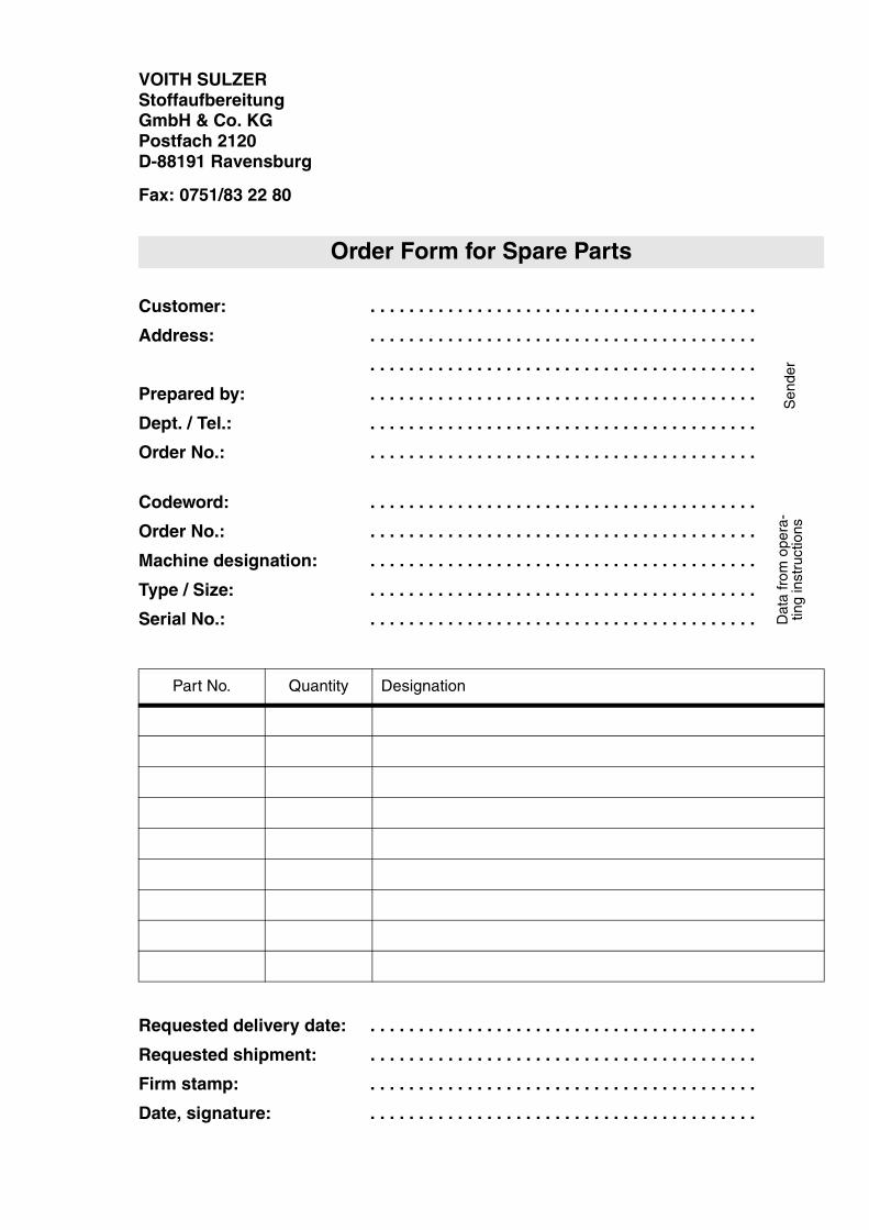
– 3 Order Forms for Spare Parts
11 Appendix
F2-T-GB Appendix 11-1

Fiberizer
11-2 Appendix F2-T-GB

VOITH SULZERStoffaufbereitungGmbH & Co. KGPostfach 2120D-88191 Ravensburg
Fax: 0751/83 22 80
Customer: . . . . . . . . . . . . . . . . . . . . . . . . . . . . . . . . . . . . . . . .
Address: . . . . . . . . . . . . . . . . . . . . . . . . . . . . . . . . . . . . . . . .
. . . . . . . . . . . . . . . . . . . . . . . . . . . . . . . . . . . . . . . .
Prepared by: . . . . . . . . . . . . . . . . . . . . . . . . . . . . . . . . . . . . . . . .
Dept. / Tel.: . . . . . . . . . . . . . . . . . . . . . . . . . . . . . . . . . . . . . . . .
Order No.: . . . . . . . . . . . . . . . . . . . . . . . . . . . . . . . . . . . . . . . .
Codeword: . . . . . . . . . . . . . . . . . . . . . . . . . . . . . . . . . . . . . . . .
Order No.: . . . . . . . . . . . . . . . . . . . . . . . . . . . . . . . . . . . . . . . .
Machine designation: . . . . . . . . . . . . . . . . . . . . . . . . . . . . . . . . . . . . . . . .
Type / Size: . . . . . . . . . . . . . . . . . . . . . . . . . . . . . . . . . . . . . . . .
Serial No.: . . . . . . . . . . . . . . . . . . . . . . . . . . . . . . . . . . . . . . . .
Requested delivery date: . . . . . . . . . . . . . . . . . . . . . . . . . . . . . . . . . . . . . . . .
Requested shipment: . . . . . . . . . . . . . . . . . . . . . . . . . . . . . . . . . . . . . . . .
Firm stamp: . . . . . . . . . . . . . . . . . . . . . . . . . . . . . . . . . . . . . . . .
Date, signature: . . . . . . . . . . . . . . . . . . . . . . . . . . . . . . . . . . . . . . . .
Order Form for Spare Parts
Part No. Quantity Designation
Sen
der
Dat
a fr
om o
pera
-tin
g in
stru
ctio
ns

VOITH SULZERStoffaufbereitung GmbH & Co. KGPostfach 2120D-88191 Ravensburg
Fax: 0751/83 22 80
Customer: . . . . . . . . . . . . . . . . . . . . . . . . . . . . . . . . . . . . . . . .
Address: . . . . . . . . . . . . . . . . . . . . . . . . . . . . . . . . . . . . . . . .
. . . . . . . . . . . . . . . . . . . . . . . . . . . . . . . . . . . . . . . .
Prepared by: . . . . . . . . . . . . . . . . . . . . . . . . . . . . . . . . . . . . . . . .
Dept. / Tel.: . . . . . . . . . . . . . . . . . . . . . . . . . . . . . . . . . . . . . . . .
Order No.: . . . . . . . . . . . . . . . . . . . . . . . . . . . . . . . . . . . . . . . .
Codeword: . . . . . . . . . . . . . . . . . . . . . . . . . . . . . . . . . . . . . . . .
Order No.: . . . . . . . . . . . . . . . . . . . . . . . . . . . . . . . . . . . . . . . .
Machine designation: . . . . . . . . . . . . . . . . . . . . . . . . . . . . . . . . . . . . . . . .
Type / Size: . . . . . . . . . . . . . . . . . . . . . . . . . . . . . . . . . . . . . . . .
Serial No.: . . . . . . . . . . . . . . . . . . . . . . . . . . . . . . . . . . . . . . . .
Requested delivery date: . . . . . . . . . . . . . . . . . . . . . . . . . . . . . . . . . . . . . . . .
Requested shipment: . . . . . . . . . . . . . . . . . . . . . . . . . . . . . . . . . . . . . . . .
Firm stamp: . . . . . . . . . . . . . . . . . . . . . . . . . . . . . . . . . . . . . . . .
Date, signature: . . . . . . . . . . . . . . . . . . . . . . . . . . . . . . . . . . . . . . . .
Order Form for Spare Parts
Part No. Quantity Designation
Sen
der
Dat
a fr
om o
pera
-tin
g in
stru
ctio
ns


VOITH SULZERStoffaufbereitungGmbH & Co. KGPostfach 2120D-88191 Ravensburg
Fax: 0751/83 22 80
Customer: . . . . . . . . . . . . . . . . . . . . . . . . . . . . . . . . . . . . . . . .
Address: . . . . . . . . . . . . . . . . . . . . . . . . . . . . . . . . . . . . . . . .
. . . . . . . . . . . . . . . . . . . . . . . . . . . . . . . . . . . . . . . .
Prepared by: . . . . . . . . . . . . . . . . . . . . . . . . . . . . . . . . . . . . . . . .
Dept. / Tel.: . . . . . . . . . . . . . . . . . . . . . . . . . . . . . . . . . . . . . . . .
Order No.: . . . . . . . . . . . . . . . . . . . . . . . . . . . . . . . . . . . . . . . .
Codeword: . . . . . . . . . . . . . . . . . . . . . . . . . . . . . . . . . . . . . . . .
Order No.: . . . . . . . . . . . . . . . . . . . . . . . . . . . . . . . . . . . . . . . .
Machine designation: . . . . . . . . . . . . . . . . . . . . . . . . . . . . . . . . . . . . . . . .
Type / Size: . . . . . . . . . . . . . . . . . . . . . . . . . . . . . . . . . . . . . . . .
Serial No.: . . . . . . . . . . . . . . . . . . . . . . . . . . . . . . . . . . . . . . . .
Requested delivery date: . . . . . . . . . . . . . . . . . . . . . . . . . . . . . . . . . . . . . . . .
Requested shipment: . . . . . . . . . . . . . . . . . . . . . . . . . . . . . . . . . . . . . . . .
Firm stamp: . . . . . . . . . . . . . . . . . . . . . . . . . . . . . . . . . . . . . . . .
Date, signature: . . . . . . . . . . . . . . . . . . . . . . . . . . . . . . . . . . . . . . . .
Order Form for Spare Parts
Part No. Quantity Designation
Sen
der
Dat
a fr
om o
pera
-tin
g in
stru
ctio
ns

Fiberizer
Contents:
– 1 Documentation for Taper-Lock clamping bush (make Desch)
– 1 Documentation for shrink disc (make Ringfeder)
– 1 Documentation for mechanical seal (make AESSEAL)
12 Subcontractor Documentation
F2-T-GB Subcontractor Documentation 12-1

Fiberizer
12-2 Subcontractor Documentation F2-T-GB


![$YGD GH &iGL] - movilidadgranada.com · f3 f3 f3 f3 f3 f3 f3 f3 f3 f3 f3 f3f3 f3 f3 f3 f3 f3 f3 f3 f3 f3 f3 f3 f3 f3 f3 f3 f3f3 f3 f3 f3 f3 f3 f3 f3 f2 f2 f2 f2 f2 f2 f2 f2 f2 f2](https://img.dokumen.tips/doc/110x75/5bb5162f09d3f2b63a8c0773/ygd-gh-igl-f3-f3-f3-f3-f3-f3-f3-f3-f3-f3-f3-f3f3-f3-f3-f3-f3-f3-f3-f3-f3.jpg)