Embed Size (px)
Citation preview

POS15/18
Operating instructions enMode d’emploi frManual de instrucciones esManual de instruções pt
Printed: 20.04.2017 | Doc-Nr: PUB / 5135739 / 000 / 00Printed: 20.04.2017 | Doc-Nr: PUB / 5135739 / 000 / 01

1
2
Printed: 20.04.2017 | Doc-Nr: PUB / 5135739 / 000 / 00Printed: 20.04.2017 | Doc-Nr: PUB / 5135739 / 000 / 01

43
5 6
Printed: 20.04.2017 | Doc-Nr: PUB / 5135739 / 000 / 00Printed: 20.04.2017 | Doc-Nr: PUB / 5135739 / 000 / 01

7 8
9
Printed: 20.04.2017 | Doc-Nr: PUB / 5135739 / 000 / 00Printed: 20.04.2017 | Doc-Nr: PUB / 5135739 / 000 / 01

10
Printed: 20.04.2017 | Doc-Nr: PUB / 5135739 / 000 / 00Printed: 20.04.2017 | Doc-Nr: PUB / 5135739 / 000 / 01

ORIGINAL OPERATING INSTRUCTIONS
POS 15/18 total station
It is essential that the operating instructionsare read before the tool is operated for thefirst time.Always keep these operating instructions to-gether with the tool.Ensure that the operating instructions arewith the tool when it is given to other persons.
1 These numbers refer to the corresponding illustra-tions. The illustrations can be found on the fold-out coverpages. Keep these pages open while studying the oper-ating instructions.In these operating instructions, the designation “the tool”always refers to the POS 15 or POS 18.
Rear casing section 1
@Left battery compartment with cover retainingscrew
;Tribrach footscrew
=Tribrach lock
%Touch screen control panel
&Focussing knob
(Eyepiece
)Telescope with laser distancer
+Alignment sight (sighting aid)
Front casing section 2
/Vertical drive
:USB interface connectors (small and large)
·Right battery compartment with cover retainingscrew
$Horizontal drive
£Tribrach footscrew
|Tribrach
¡Laser plummet
QGuide light
WObjective lens
ECarrying handle
Contents1 General information . . . . . . . . . . . . . . . . . . . . . . . . . . . . . . . . . . . . . . . . . . . . . . . . . . . . . . . 41.1 Safety notices and their meaning . . . . . . . . . . . . . . . . . . . . . . . . . . . . . . . . . . . . . . . . . . . . . . . . . . 41.2 Explanation of the pictograms and other information . . . . . . . . . . . . . . . . . . . . . . . . . . . . . . . . . . . 52 Description . . . . . . . . . . . . . . . . . . . . . . . . . . . . . . . . . . . . . . . . . . . . . . . . . . . . . . . . . . . . . . . . 52.1 Use of the product as directed . . . . . . . . . . . . . . . . . . . . . . . . . . . . . . . . . . . . . . . . . . . . . . . . . . . . 52.2 Description of the tool . . . . . . . . . . . . . . . . . . . . . . . . . . . . . . . . . . . . . . . . . . . . . . . . . . . . . . . . . . 52.3 Items supplied as standard . . . . . . . . . . . . . . . . . . . . . . . . . . . . . . . . . . . . . . . . . . . . . . . . . . . . . . 63 Accessories . . . . . . . . . . . . . . . . . . . . . . . . . . . . . . . . . . . . . . . . . . . . . . . . . . . . . . . . . . . . . . . 64 Technical data . . . . . . . . . . . . . . . . . . . . . . . . . . . . . . . . . . . . . . . . . . . . . . . . . . . . . . . . . . . . . 85 Safety instructions . . . . . . . . . . . . . . . . . . . . . . . . . . . . . . . . . . . . . . . . . . . . . . . . . . . . . . . . 95.1 Basic information concerning safety . . . . . . . . . . . . . . . . . . . . . . . . . . . . . . . . . . . . . . . . . . . . . . . 95.2 Misuse . . . . . . . . . . . . . . . . . . . . . . . . . . . . . . . . . . . . . . . . . . . . . . . . . . . . . . . . . . . . . . . . . . . . . . 95.3 Proper organization of the work area . . . . . . . . . . . . . . . . . . . . . . . . . . . . . . . . . . . . . . . . . . . . . . 105.4 Electromagnetic compatibility . . . . . . . . . . . . . . . . . . . . . . . . . . . . . . . . . . . . . . . . . . . . . . . . . . . 105.4.1 Laser classification for Laser Class 2 products . . . . . . . . . . . . . . . . . . . . . . . . . . . . . . . . . . . . . . . 105.4.2 Laser classification for Laser Class 3R products . . . . . . . . . . . . . . . . . . . . . . . . . . . . . . . . . . . . . . 105.5 General safety rules . . . . . . . . . . . . . . . . . . . . . . . . . . . . . . . . . . . . . . . . . . . . . . . . . . . . . . . . . . . 105.6 Transport . . . . . . . . . . . . . . . . . . . . . . . . . . . . . . . . . . . . . . . . . . . . . . . . . . . . . . . . . . . . . . . . . . . 116 Description of the system. . . . . . . . . . . . . . . . . . . . . . . . . . . . . . . . . . . . . . . . . . . . . . . . 116.1 General terms . . . . . . . . . . . . . . . . . . . . . . . . . . . . . . . . . . . . . . . . . . . . . . . . . . . . . . . . . . . . . . . 116.1.1 Coordinates . . . . . . . . . . . . . . . . . . . . . . . . . . . . . . . . . . . . . . . . . . . . . . . . . . . . . . . . . . . . . . . . 116.1.2 Control lines . . . . . . . . . . . . . . . . . . . . . . . . . . . . . . . . . . . . . . . . . . . . . . . . . . . . . . . . . . . . . . . . 11
en
1Printed: 20.04.2017 | Doc-Nr: PUB / 5135739 / 000 / 00Printed: 20.04.2017 | Doc-Nr: PUB / 5135739 / 000 / 01

6.1.3 Technical terms . . . . . . . . . . . . . . . . . . . . . . . . . . . . . . . . . . . . . . . . . . . . . . . . . . . . . . . . . . . . . . 126.1.4 Telescope positions 4 3 . . . . . . . . . . . . . . . . . . . . . . . . . . . . . . . . . . . . . . . . . . . . . . . . . . . . . . 136.1.5 Terms and their description . . . . . . . . . . . . . . . . . . . . . . . . . . . . . . . . . . . . . . . . . . . . . . . . . . . . . 136.1.6 Abbreviations and their meaning . . . . . . . . . . . . . . . . . . . . . . . . . . . . . . . . . . . . . . . . . . . . . . . . . 146.2 Angle measurement system . . . . . . . . . . . . . . . . . . . . . . . . . . . . . . . . . . . . . . . . . . . . . . . . . . . . . 156.2.1 Measuring principle . . . . . . . . . . . . . . . . . . . . . . . . . . . . . . . . . . . . . . . . . . . . . . . . . . . . . . . . . . . 156.2.2 Dual-axis compensator 5 . . . . . . . . . . . . . . . . . . . . . . . . . . . . . . . . . . . . . . . . . . . . . . . . . . . . . . 156.3 Distance measurement . . . . . . . . . . . . . . . . . . . . . . . . . . . . . . . . . . . . . . . . . . . . . . . . . . . . . . . . 156.3.1 Distance measurement 6 . . . . . . . . . . . . . . . . . . . . . . . . . . . . . . . . . . . . . . . . . . . . . . . . . . . . . . 156.3.2 Targets . . . . . . . . . . . . . . . . . . . . . . . . . . . . . . . . . . . . . . . . . . . . . . . . . . . . . . . . . . . . . . . . . . . . 166.3.3 Reflector rod . . . . . . . . . . . . . . . . . . . . . . . . . . . . . . . . . . . . . . . . . . . . . . . . . . . . . . . . . . . . . . . . 166.4 Height measurement . . . . . . . . . . . . . . . . . . . . . . . . . . . . . . . . . . . . . . . . . . . . . . . . . . . . . . . . . . 176.4.1 Height measurement . . . . . . . . . . . . . . . . . . . . . . . . . . . . . . . . . . . . . . . . . . . . . . . . . . . . . . . . . . 176.5 Guide light . . . . . . . . . . . . . . . . . . . . . . . . . . . . . . . . . . . . . . . . . . . . . . . . . . . . . . . . . . . . . . . . . . 186.5.1 Guide light 7 . . . . . . . . . . . . . . . . . . . . . . . . . . . . . . . . . . . . . . . . . . . . . . . . . . . . . . . . . . . . . . . 186.6 Laser pointer 6 . . . . . . . . . . . . . . . . . . . . . . . . . . . . . . . . . . . . . . . . . . . . . . . . . . . . . . . . . . . . . . 186.7 Data points . . . . . . . . . . . . . . . . . . . . . . . . . . . . . . . . . . . . . . . . . . . . . . . . . . . . . . . . . . . . . . . . . . 186.7.1 Selecting points . . . . . . . . . . . . . . . . . . . . . . . . . . . . . . . . . . . . . . . . . . . . . . . . . . . . . . . . . . . . . 187 First steps . . . . . . . . . . . . . . . . . . . . . . . . . . . . . . . . . . . . . . . . . . . . . . . . . . . . . . . . . . . . . . . . 207.1 Batteries . . . . . . . . . . . . . . . . . . . . . . . . . . . . . . . . . . . . . . . . . . . . . . . . . . . . . . . . . . . . . . . . . . . 207.2 Charging the battery . . . . . . . . . . . . . . . . . . . . . . . . . . . . . . . . . . . . . . . . . . . . . . . . . . . . . . . . . . 207.3 Inserting and changing the battery 8 . . . . . . . . . . . . . . . . . . . . . . . . . . . . . . . . . . . . . . . . . . . . . . 207.4 Checking functions . . . . . . . . . . . . . . . . . . . . . . . . . . . . . . . . . . . . . . . . . . . . . . . . . . . . . . . . . . . 207.5 Control panel . . . . . . . . . . . . . . . . . . . . . . . . . . . . . . . . . . . . . . . . . . . . . . . . . . . . . . . . . . . . . . . . 207.5.1 Function buttons . . . . . . . . . . . . . . . . . . . . . . . . . . . . . . . . . . . . . . . . . . . . . . . . . . . . . . . . . . . . . 207.5.2 Size of the touch screen . . . . . . . . . . . . . . . . . . . . . . . . . . . . . . . . . . . . . . . . . . . . . . . . . . . . . . . 217.5.3 Division of the touch screen . . . . . . . . . . . . . . . . . . . . . . . . . . . . . . . . . . . . . . . . . . . . . . . . . . . . . 217.5.4 Touch screen – numerical keyboard . . . . . . . . . . . . . . . . . . . . . . . . . . . . . . . . . . . . . . . . . . . . . . . 217.5.5 Touch screen – alphanumerical keyboard . . . . . . . . . . . . . . . . . . . . . . . . . . . . . . . . . . . . . . . . . . . 227.5.6 Touch screen – general operating controls . . . . . . . . . . . . . . . . . . . . . . . . . . . . . . . . . . . . . . . . . . 227.5.7 Laser pointer status indicator . . . . . . . . . . . . . . . . . . . . . . . . . . . . . . . . . . . . . . . . . . . . . . . . . . . . 227.5.8 Battery condition indicators . . . . . . . . . . . . . . . . . . . . . . . . . . . . . . . . . . . . . . . . . . . . . . . . . . . . . 227.6 Switching on / off . . . . . . . . . . . . . . . . . . . . . . . . . . . . . . . . . . . . . . . . . . . . . . . . . . . . . . . . . . . . . 237.6.1 Switching on . . . . . . . . . . . . . . . . . . . . . . . . . . . . . . . . . . . . . . . . . . . . . . . . . . . . . . . . . . . . . . . . 237.6.2 Switching off . . . . . . . . . . . . . . . . . . . . . . . . . . . . . . . . . . . . . . . . . . . . . . . . . . . . . . . . . . . . . . . . 237.7 Setting up the tool . . . . . . . . . . . . . . . . . . . . . . . . . . . . . . . . . . . . . . . . . . . . . . . . . . . . . . . . . . . . 237.7.1 Setting up over a mark on the floor or ground using the laser plummet . . . . . . . . . . . . . . . . . . . . . . 237.7.2 Setting up the tool 9 . . . . . . . . . . . . . . . . . . . . . . . . . . . . . . . . . . . . . . . . . . . . . . . . . . . . . . . . . . 237.7.3 Setting up over a pipe using the laser plummet . . . . . . . . . . . . . . . . . . . . . . . . . . . . . . . . . . . . . . . 247.8 Theodolite application . . . . . . . . . . . . . . . . . . . . . . . . . . . . . . . . . . . . . . . . . . . . . . . . . . . . . . . . . 247.8.1 Setting the horizontal circle display . . . . . . . . . . . . . . . . . . . . . . . . . . . . . . . . . . . . . . . . . . . . . . . . 257.8.2 Entering a circle reading manually . . . . . . . . . . . . . . . . . . . . . . . . . . . . . . . . . . . . . . . . . . . . . . . . 257.8.3 Zeroing the circle reading . . . . . . . . . . . . . . . . . . . . . . . . . . . . . . . . . . . . . . . . . . . . . . . . . . . . . . 267.8.4 Inclination indicator 10 . . . . . . . . . . . . . . . . . . . . . . . . . . . . . . . . . . . . . . . . . . . . . . . . . . . . . . . . . 268 System settings . . . . . . . . . . . . . . . . . . . . . . . . . . . . . . . . . . . . . . . . . . . . . . . . . . . . . . . . . . 278.1 Configuration . . . . . . . . . . . . . . . . . . . . . . . . . . . . . . . . . . . . . . . . . . . . . . . . . . . . . . . . . . . . . . . . 278.1.1 Settings . . . . . . . . . . . . . . . . . . . . . . . . . . . . . . . . . . . . . . . . . . . . . . . . . . . . . . . . . . . . . . . . . . . 278.2 Time and date . . . . . . . . . . . . . . . . . . . . . . . . . . . . . . . . . . . . . . . . . . . . . . . . . . . . . . . . . . . . . . . 299 Function menu (FNC) . . . . . . . . . . . . . . . . . . . . . . . . . . . . . . . . . . . . . . . . . . . . . . . . . . . . . 309.1 Guide light 7 . . . . . . . . . . . . . . . . . . . . . . . . . . . . . . . . . . . . . . . . . . . . . . . . . . . . . . . . . . . . . . . . 309.2 Laser pointer 6 . . . . . . . . . . . . . . . . . . . . . . . . . . . . . . . . . . . . . . . . . . . . . . . . . . . . . . . . . . . . . . 319.3 Display illumination . . . . . . . . . . . . . . . . . . . . . . . . . . . . . . . . . . . . . . . . . . . . . . . . . . . . . . . . . . . 31
en
2Printed: 20.04.2017 | Doc-Nr: PUB / 5135739 / 000 / 00Printed: 20.04.2017 | Doc-Nr: PUB / 5135739 / 000 / 01
9.4 Electronic bubble level . . . . . . . . . . . . . . . . . . . . . . . . . . . . . . . . . . . . . . . . . . . . . . . . . . . . . . . . . 319.5 Correction of atmospheric influences . . . . . . . . . . . . . . . . . . . . . . . . . . . . . . . . . . . . . . . . . . . . . 319.5.1 Correction of atmospheric influences . . . . . . . . . . . . . . . . . . . . . . . . . . . . . . . . . . . . . . . . . . . . . . 3210 Functions required for various applications . . . . . . . . . . . . . . . . . . . . . . . . . . . . 3210.1 Projects . . . . . . . . . . . . . . . . . . . . . . . . . . . . . . . . . . . . . . . . . . . . . . . . . . . . . . . . . . . . . . . . . . . . 3210.1.1 Showing the active project . . . . . . . . . . . . . . . . . . . . . . . . . . . . . . . . . . . . . . . . . . . . . . . . . . . . . . 3210.1.2 Selecting a project . . . . . . . . . . . . . . . . . . . . . . . . . . . . . . . . . . . . . . . . . . . . . . . . . . . . . . . . . . . 3310.1.3 Creating a new project . . . . . . . . . . . . . . . . . . . . . . . . . . . . . . . . . . . . . . . . . . . . . . . . . . . . . . . . . 3310.1.4 Project information . . . . . . . . . . . . . . . . . . . . . . . . . . . . . . . . . . . . . . . . . . . . . . . . . . . . . . . . . . . 3410.2 Setting a station and orientation . . . . . . . . . . . . . . . . . . . . . . . . . . . . . . . . . . . . . . . . . . . . . . . . . 3410.2.1 Overview . . . . . . . . . . . . . . . . . . . . . . . . . . . . . . . . . . . . . . . . . . . . . . . . . . . . . . . . . . . . . . . . . . 3410.2.2 Setting a station over a point with control lines . . . . . . . . . . . . . . . . . . . . . . . . . . . . . . . . . . . . . . . 3510.2.3 Setting a station “anywhere”, with building control lines . . . . . . . . . . . . . . . . . . . . . . . . . . . . . . . . . 3810.2.4 Setting a station over a point with coordinates . . . . . . . . . . . . . . . . . . . . . . . . . . . . . . . . . . . . . . . . 4110.2.5 Setting a station “anywhere”, with coordinates . . . . . . . . . . . . . . . . . . . . . . . . . . . . . . . . . . . . . . . 4310.3 Setting the height . . . . . . . . . . . . . . . . . . . . . . . . . . . . . . . . . . . . . . . . . . . . . . . . . . . . . . . . . . . . . 4610.3.1 Setting a station with a control line (height option “on”) . . . . . . . . . . . . . . . . . . . . . . . . . . . . . . . . . 4610.3.2 Setting a station with coordinates (height option “on”) . . . . . . . . . . . . . . . . . . . . . . . . . . . . . . . . . . 4811 Applications . . . . . . . . . . . . . . . . . . . . . . . . . . . . . . . . . . . . . . . . . . . . . . . . . . . . . . . . . . . . . . 5011.1 Horizontal layout (Horz. layout) . . . . . . . . . . . . . . . . . . . . . . . . . . . . . . . . . . . . . . . . . . . . . . . . . . 5011.1.1 The horizontal layout principle . . . . . . . . . . . . . . . . . . . . . . . . . . . . . . . . . . . . . . . . . . . . . . . . . . . 5011.1.2 Laying out with building control lines . . . . . . . . . . . . . . . . . . . . . . . . . . . . . . . . . . . . . . . . . . . . . . 5111.1.3 Laying out with coordinates . . . . . . . . . . . . . . . . . . . . . . . . . . . . . . . . . . . . . . . . . . . . . . . . . . . . . 5411.2 Vertical layout (Vert. layout) . . . . . . . . . . . . . . . . . . . . . . . . . . . . . . . . . . . . . . . . . . . . . . . . . . . . . 5711.2.1 The vertical layout principle . . . . . . . . . . . . . . . . . . . . . . . . . . . . . . . . . . . . . . . . . . . . . . . . . . . . . 5711.2.2 Vertical layout with building control lines . . . . . . . . . . . . . . . . . . . . . . . . . . . . . . . . . . . . . . . . . . . . 5811.2.3 Vertical layout with coordinates . . . . . . . . . . . . . . . . . . . . . . . . . . . . . . . . . . . . . . . . . . . . . . . . . . 6111.3 As-built . . . . . . . . . . . . . . . . . . . . . . . . . . . . . . . . . . . . . . . . . . . . . . . . . . . . . . . . . . . . . . . . . . . . 6311.3.1 The principle of “As-built” . . . . . . . . . . . . . . . . . . . . . . . . . . . . . . . . . . . . . . . . . . . . . . . . . . . . . . 6311.3.2 As-built with building control lines . . . . . . . . . . . . . . . . . . . . . . . . . . . . . . . . . . . . . . . . . . . . . . . . 6411.3.3 As-built with coordinates . . . . . . . . . . . . . . . . . . . . . . . . . . . . . . . . . . . . . . . . . . . . . . . . . . . . . . . 6611.4 Missing line . . . . . . . . . . . . . . . . . . . . . . . . . . . . . . . . . . . . . . . . . . . . . . . . . . . . . . . . . . . . . . . . . 6711.4.1 The principle of “Missing line” . . . . . . . . . . . . . . . . . . . . . . . . . . . . . . . . . . . . . . . . . . . . . . . . . . . 6711.5 Measure and record . . . . . . . . . . . . . . . . . . . . . . . . . . . . . . . . . . . . . . . . . . . . . . . . . . . . . . . . . . . 7011.5.1 The principle of “Measure and record” . . . . . . . . . . . . . . . . . . . . . . . . . . . . . . . . . . . . . . . . . . . . . 7011.5.2 Measure and record with building control lines . . . . . . . . . . . . . . . . . . . . . . . . . . . . . . . . . . . . . . . 7011.5.3 Measure and record with coordinates . . . . . . . . . . . . . . . . . . . . . . . . . . . . . . . . . . . . . . . . . . . . . . 7211.6 Vertical alignment . . . . . . . . . . . . . . . . . . . . . . . . . . . . . . . . . . . . . . . . . . . . . . . . . . . . . . . . . . . . 7311.6.1 The principle of “Vertical alignment” . . . . . . . . . . . . . . . . . . . . . . . . . . . . . . . . . . . . . . . . . . . . . . . 7311.7 Area measurement . . . . . . . . . . . . . . . . . . . . . . . . . . . . . . . . . . . . . . . . . . . . . . . . . . . . . . . . . . . . 7411.7.1 The principle of area measurement . . . . . . . . . . . . . . . . . . . . . . . . . . . . . . . . . . . . . . . . . . . . . . . . 7411.8 Indirect height measurement . . . . . . . . . . . . . . . . . . . . . . . . . . . . . . . . . . . . . . . . . . . . . . . . . . . . 7611.8.1 The principle of indirect height measurement . . . . . . . . . . . . . . . . . . . . . . . . . . . . . . . . . . . . . . . . 7611.8.2 Indirect height measurement . . . . . . . . . . . . . . . . . . . . . . . . . . . . . . . . . . . . . . . . . . . . . . . . . . . . 7711.9 Determining a point in relation to an axis . . . . . . . . . . . . . . . . . . . . . . . . . . . . . . . . . . . . . . . . . . . 7811.9.1 The principle of “Point in relation to axis” . . . . . . . . . . . . . . . . . . . . . . . . . . . . . . . . . . . . . . . . . . . 7811.9.2 Determining the axis . . . . . . . . . . . . . . . . . . . . . . . . . . . . . . . . . . . . . . . . . . . . . . . . . . . . . . . . . . 7811.9.3 Checking points in relation to the axis . . . . . . . . . . . . . . . . . . . . . . . . . . . . . . . . . . . . . . . . . . . . . . 7912 Data and data handling . . . . . . . . . . . . . . . . . . . . . . . . . . . . . . . . . . . . . . . . . . . . . . . . . . 8012.1 Introduction . . . . . . . . . . . . . . . . . . . . . . . . . . . . . . . . . . . . . . . . . . . . . . . . . . . . . . . . . . . . . . . . . 80
en
3Printed: 20.04.2017 | Doc-Nr: PUB / 5135739 / 000 / 00Printed: 20.04.2017 | Doc-Nr: PUB / 5135739 / 000 / 01

12.2 Point data . . . . . . . . . . . . . . . . . . . . . . . . . . . . . . . . . . . . . . . . . . . . . . . . . . . . . . . . . . . . . . . . . . . 8012.2.1 Points in the form of measured points . . . . . . . . . . . . . . . . . . . . . . . . . . . . . . . . . . . . . . . . . . . . . . 8012.2.2 Points in the form of coordinate points . . . . . . . . . . . . . . . . . . . . . . . . . . . . . . . . . . . . . . . . . . . . . 8012.2.3 Points with graphical elements . . . . . . . . . . . . . . . . . . . . . . . . . . . . . . . . . . . . . . . . . . . . . . . . . . . 8012.3 Generation of point data . . . . . . . . . . . . . . . . . . . . . . . . . . . . . . . . . . . . . . . . . . . . . . . . . . . . . . . . 8012.3.1 With the total station . . . . . . . . . . . . . . . . . . . . . . . . . . . . . . . . . . . . . . . . . . . . . . . . . . . . . . . . . . 8012.3.2 With Hilti PROFIS Layout . . . . . . . . . . . . . . . . . . . . . . . . . . . . . . . . . . . . . . . . . . . . . . . . . . . . . . . 8112.4 Data memory . . . . . . . . . . . . . . . . . . . . . . . . . . . . . . . . . . . . . . . . . . . . . . . . . . . . . . . . . . . . . . . . 8112.4.1 Total station internal memory . . . . . . . . . . . . . . . . . . . . . . . . . . . . . . . . . . . . . . . . . . . . . . . . . . . . 8112.4.2 USB memory . . . . . . . . . . . . . . . . . . . . . . . . . . . . . . . . . . . . . . . . . . . . . . . . . . . . . . . . . . . . . . . 8113 Total station data manager . . . . . . . . . . . . . . . . . . . . . . . . . . . . . . . . . . . . . . . . . . . . . . 8113.1 Overview . . . . . . . . . . . . . . . . . . . . . . . . . . . . . . . . . . . . . . . . . . . . . . . . . . . . . . . . . . . . . . . . . . . 8113.2 Selecting a job . . . . . . . . . . . . . . . . . . . . . . . . . . . . . . . . . . . . . . . . . . . . . . . . . . . . . . . . . . . . . . . 8213.2.1 Fixed points (control points or layout points) . . . . . . . . . . . . . . . . . . . . . . . . . . . . . . . . . . . . . . . . . 8313.2.2 Measured points . . . . . . . . . . . . . . . . . . . . . . . . . . . . . . . . . . . . . . . . . . . . . . . . . . . . . . . . . . . . . 8413.3 Deleting a project . . . . . . . . . . . . . . . . . . . . . . . . . . . . . . . . . . . . . . . . . . . . . . . . . . . . . . . . . . . . . 8613.4 Creating a new project . . . . . . . . . . . . . . . . . . . . . . . . . . . . . . . . . . . . . . . . . . . . . . . . . . . . . . . . . 8713.5 Copying a project . . . . . . . . . . . . . . . . . . . . . . . . . . . . . . . . . . . . . . . . . . . . . . . . . . . . . . . . . . . . . 8714 Exchanging data with a PC . . . . . . . . . . . . . . . . . . . . . . . . . . . . . . . . . . . . . . . . . . . . . . 8814.1 Introduction . . . . . . . . . . . . . . . . . . . . . . . . . . . . . . . . . . . . . . . . . . . . . . . . . . . . . . . . . . . . . . . . . 8814.2 HILTI PROFIS Layout . . . . . . . . . . . . . . . . . . . . . . . . . . . . . . . . . . . . . . . . . . . . . . . . . . . . . . . . . . 8814.2.1 Data types . . . . . . . . . . . . . . . . . . . . . . . . . . . . . . . . . . . . . . . . . . . . . . . . . . . . . . . . . . . . . . . . . 8814.2.2 Hilti PROFIS Layout data output (export) . . . . . . . . . . . . . . . . . . . . . . . . . . . . . . . . . . . . . . . . . . . . 8914.2.3 Hilti PROFIS Layout data input (import) . . . . . . . . . . . . . . . . . . . . . . . . . . . . . . . . . . . . . . . . . . . . . 8915 Calibration and adjustment . . . . . . . . . . . . . . . . . . . . . . . . . . . . . . . . . . . . . . . . . . . . . . 8915.1 In-the-field calibration . . . . . . . . . . . . . . . . . . . . . . . . . . . . . . . . . . . . . . . . . . . . . . . . . . . . . . . . . 8915.2 In-the-field calibration . . . . . . . . . . . . . . . . . . . . . . . . . . . . . . . . . . . . . . . . . . . . . . . . . . . . . . . . . 9015.3 Hilti Calibration Service . . . . . . . . . . . . . . . . . . . . . . . . . . . . . . . . . . . . . . . . . . . . . . . . . . . . . . . . 9216 Care and maintenance . . . . . . . . . . . . . . . . . . . . . . . . . . . . . . . . . . . . . . . . . . . . . . . . . . . 9316.1 Cleaning and drying . . . . . . . . . . . . . . . . . . . . . . . . . . . . . . . . . . . . . . . . . . . . . . . . . . . . . . . . . . . 9316.2 Storage . . . . . . . . . . . . . . . . . . . . . . . . . . . . . . . . . . . . . . . . . . . . . . . . . . . . . . . . . . . . . . . . . . . . 9316.3 Transport . . . . . . . . . . . . . . . . . . . . . . . . . . . . . . . . . . . . . . . . . . . . . . . . . . . . . . . . . . . . . . . . . . . 9317 Disposal. . . . . . . . . . . . . . . . . . . . . . . . . . . . . . . . . . . . . . . . . . . . . . . . . . . . . . . . . . . . . . . . . . . 9318 Manufacturer’s warranty . . . . . . . . . . . . . . . . . . . . . . . . . . . . . . . . . . . . . . . . . . . . . . . . . 9419 FCC statement (applicable in US) / IC statement (applicable in
Canada) . . . . . . . . . . . . . . . . . . . . . . . . . . . . . . . . . . . . . . . . . . . . . . . . . . . . . . . . . . . . . . . . . . . 9420 EC declaration of conformity (original) . . . . . . . . . . . . . . . . . . . . . . . . . . . . . . . . . . 95
1 General information1.1 Safety notices and their meaningDANGERDraws attention to imminent danger that will lead toserious bodily injury or fatality.
WARNINGDraws attention to a potentially dangerous situation thatcould lead to serious personal injury or fatality.
CAUTIONDraws attention to a potentially dangerous situation thatcould lead to slight personal injury or damage to theequipment or other property.
NOTEDraws attention to an instruction or other useful informa-tion.
en
4Printed: 20.04.2017 | Doc-Nr: PUB / 5135739 / 000 / 00Printed: 20.04.2017 | Doc-Nr: PUB / 5135739 / 000 / 01

>1/4s
3R
1.2 Explanation of the pictograms and otherinformation
Symbols
Read theoperatinginstructionsbefore use.
Generalwarning
Return wastematerial forrecycling.
Do not lookinto thebeam.
Do not turnthe screw
Symbol for Laser Class II / Class 2
Laser class IIaccording to
CFR 21, § 1040(FDA)
Laser class 2according toEN60825:2008
Symbol for Laser Class III / Class 3
Laser class IIaccording to
CFR 21, § 1040 (FDA)
Do not lookinto the
beam withthe nakedeye or withoptical
instruments.
Laser exit aperture
Laser exit aperture
Location of identification data on the toolThe type designation and serial number can be found onthe type identification plate on the tool. Make a note ofthis data in your operating instructions and always referto it when making an enquiry to your Hilti representativeor service department.
Type:
Generation: 01
Serial no.:
2 Description2.1 Use of the product as directedThe tool is designed for measuring distances and direc-tions, calculating target positions in 3 dimensions andthe values derived from these positions and for layingout points using given coordinates or values relative to acontrol line.To avoid the risk of injury, use only genuine Hilti ac-cessories and insert tools.Observe the information printed in the operating instruc-tions concerning operation, care and maintenance.Take the influences of the surrounding area into account.Do not use the appliance where there is a risk of fire orexplosion.Modification of the tool is not permissible.
2.2 Description of the toolThe POS 15/18 total station can be used to determine theexact position of objects or points. The tool is equippedwith horizontal and vertical circles with digital graduation,two electronic levels (compensators), a coaxial laser dis-tancer incorporated in the telescope and an electronicprocessor system for calculating and saving data.Hilti PROFIS Layout, a PC application provided by Hilti,can be used to transfer data in both directions betweenthe total station and a PC, for data processing and forexporting data to other systems.
en
5Printed: 20.04.2017 | Doc-Nr: PUB / 5135739 / 000 / 00Printed: 20.04.2017 | Doc-Nr: PUB / 5135739 / 000 / 01

2.3 Items supplied as standard1 Total station1 AC adapter incl. charging cable for chargers1 Charger2 3.8 V 5200 mAh Li-ion battery1 Reflector rod1 POW 10 adjusting key2 Laser warning plate1 Manufacturer’s certificate1 Operating instructions1 Hilti toolbox1 Optional: Hilti PROFIS Layout (PC software on
CD‑ROM)1 Optional: Copy protection dongle for PC soft-
ware1 Optional: USB data cable
3 AccessoriesIllustration Designation Description
POA 80 battery
POA 81 AC adapter
POA 82 charger
POA 50 reflector rod (metric) The POA 50 (metric) reflector rod(consisting of four sections (eachwith a length of 300 mm), the rodpoint (length 50 mm) and the reflectorplate (height 100 mm or, respectively,50 mm to the middle)) is used to takereadings from points on the ground.
en
6Printed: 20.04.2017 | Doc-Nr: PUB / 5135739 / 000 / 00Printed: 20.04.2017 | Doc-Nr: PUB / 5135739 / 000 / 01

Illustration Designation DescriptionPOA 51 reflector rod (imperial) The POA 51 (imperial) reflector rod
(consisting of four sections (each witha length of 12" ), the rod point (length2.03") and the reflector plate (height3.93" or, respectively, 1.97" to themiddle)) is used to take readings frompoints on the ground.
POAW‑4 reflector foil A self-adhesive foil for placing refer-ence points on raised targets such aswalls or posts.
PUA 35 tripod
POW 10 adjusting key For use by appropriately experiencedpersons only!
Hilti PROFIS Layout PC application that allows positions(points) to be generated from CADdata and transferred to the tool.
POA 91 copy protection dongle
POW 90 data cable
en
7Printed: 20.04.2017 | Doc-Nr: PUB / 5135739 / 000 / 00Printed: 20.04.2017 | Doc-Nr: PUB / 5135739 / 000 / 01

4 Technical dataRight of technical changes reserved.
NOTEThe only difference between the two tools is their angle measurement accuracy.
TelescopeTelescope magnification 30xShortest target distance 1.5 m (4.9 ft)Telescope angle of view 1° 20': 2.3 m / 100 m (7.0 ft / 300 ft)Objective lens aperture 45 mm (1.8")
CompensatorType Dual-axis, liquidWorking range ±3’Accuracy 2"
Angle measurementPOS 15 accuracy (DIN 18723) 5"POS 18 accuracy (DIN 18723) 3"Angle reading system Diametral
Distance measurementRange 340 m (1000 ft) Kodak 90% grayAccuracy ±3 mm + 2 ppm (0.01 ft + 2 ppm)Laser class Class 3R, visible, 630-680 nm, Po < 4.75 mW, f = 320-
400 MHz (EN 60825-1/ IEC 60825-1); Class III (CFR 21§ 1040 (FDA))
Guide lightAperture angle 1.4°Typical range 70 m (230 ft)
Laser plummetAccuracy 1.5 mm at 1.5 m (1/16 at 3 ft)Laser class Class 2, visible, 635 nm, Po < 10 mW (EN 60825-1/ IEC
60825-1); Class II (CFR 21 §1040 (FDA)
Data memoryMemory size (data blocks) 10,000Data transfer interfaces Host and client, 2 x USB
DisplayType Color display (touch screen), 320 x 240 pixelsIllumination 5 levelsContrast Day / night mode selectable
IP protection classClass IP 56
en
8Printed: 20.04.2017 | Doc-Nr: PUB / 5135739 / 000 / 00Printed: 20.04.2017 | Doc-Nr: PUB / 5135739 / 000 / 01

Horizontal driveType Continuous
Tripod threadTribrach thread 5/8''
POA 80 batteryType Li-ionRated voltage 3.8 VBattery capacity 5,200 mAhCharging time 4 hBattery life (with distance / angle measurement every30 seconds)
16 h
Weight 0.1 kg (0.2 lbs)Dimensions 67 mm x 39 mm x 25 mm (2.6" x 1.5" x 1.0")
POA 81 AC adapter and POA 82 chargerAC supply 100…240 VAC frequency 47…63 HzRated current input 4 ARated voltage 5 VWeight (POA 81 AC adapter) 0.25 kg (0.6 lbs)Weight (POA 82 charger) 0.06 kg (0.1 lbs)Dimensions (POA 81 AC adapter) 108 mm x 65 mm x 40 mm (4.3" x 2.6" x 0.1")Dimensions (POA 82 charger) 100 mm x 57 mm x 37 mm (4.0" x 2.2" x 1.5")
TemperatureOperating temperature range -20…+50°C (-4°F to +122°F)Storage temperature range -30…+70°C (-22°F to +158°F)
Dimensions and weightsDimensions 149 mm x 145 mm x 306 mm (5.9" x 5.7" x 12")Weight 4.0 kg (8.8 lbs)
5 Safety instructions5.1 Basic information concerning safetyIn addition to the information relevant to safety givenin each of the sections of these operating instructions,the following points must be strictly observed at alltimes.
5.2 MisuseThe tool and its ancillary equipment may present hazardswhen used incorrectly by untrained personnel or whenused not as directed.
a) Never use the tool without having received the ap-propriate instruction on its use or without havingread these operating instructions.
b) Do not render safety devices ineffective and donot remove information and warning notices.
c) Have the tool repaired only at a Hilti Service Center.Failure to follow the correct procedures when
en
9Printed: 20.04.2017 | Doc-Nr: PUB / 5135739 / 000 / 00Printed: 20.04.2017 | Doc-Nr: PUB / 5135739 / 000 / 01

opening the tool may cause emission of laserradiation in excess of class 3R.
d) Modification of the power tool or tampering with itsparts is not permissible.
e) The grip is designed to have a certain amount of playat one side. This is not a fault. It serves to protectthe alidade. Tightening the screws on the grip maycause damage to the thread, making costly repairsnecessary. Do not tighten any screws on the grip!
f) To avoid the risk of injury, use only genuine Hiltiaccessories and additional equipment.
g) Do not use the tool in areas where there is adanger of explosion.
h) Use only clean, soft cloths for cleaning. If necessary,they may be moistened with a little alcohol.
i) Keep laser tools out of reach of children.j) Measurements to plastic foam surfaces, e.g. poly-
styrene foam, to snow or to highly reflective surfaces,may result in incorrect readings.
k) Measurements taken to surfaces with low reflectivityin highly reflective surroundings may be inaccurate.
l) Measurements taken through panes of glass or otherobjects may be inaccurate.
m) Rapid changes in the conditions under which themeasurement is taken, e.g. persons walking throughthe laser beam, may lead to inaccurate results.
n) Do not point the tool toward the sun or other powerfullight sources.
o) Do not use the tool as a level.p) Check the tool before taking important measure-
ments or after it has been dropped or subjected tomechanical effects such as impact or vibration.
5.3 Proper organization of the work areaa) Secure the area in which you are working and take
care to avoid directing the beam toward other per-sons or toward yourself when setting up the tool.
b) Use the tool only within the defined application limits,i.e. do not take readings from mirrors, stainless steelor polished stone, etc.
c) Observe the accident prevention regulations applic-able in your country.
5.4 Electromagnetic compatibilityAlthough the tool complies with the strict requirementsof the applicable directives, Hilti cannot entirely rule outthe possibility of the tool- causing interference to other devices (e.g. aircraft nav-igation equipment) or being subject to
- interference caused by powerful electromagnetic radi-ation, leading to incorrect operation.
Check the accuracy of the tool by taking measurementsby other means when working under such conditions orif you are unsure.
5.4.1 Laser classification for Laser Class 2products
The laser plummet incorporated in the tools conformsto Laser Class 2 based on the IEC825-1 / EN60825-
01:2008 standard and to CFR 21 § 1040 (Laser Notice50). The eyelid closure reflex protects the eyes when aperson looks into the beam unintentionally for a briefmoment. This eyelid closure reflex, however, may benegatively affected by medicines, alcohol or drugs. Thistool may be used without need for further protectivemeasures. Nevertheless, as with the sun, one should notlook directly into sources of bright light. Do not direct thelaser beam toward persons.
5.4.2 Laser classification for Laser Class 3Rproducts
Themeasuring laser incorporated in the tools for distancemeasurement conforms to Laser Class 3R based on theIEC825-1 / EN60825-1:2008 standard and to CFR 21 §1040 (Laser Notice 50). This tool may be used withoutneed for further protectivemeasures. Do not stare into thebeam and do not direct the beam toward other persons.
a) Tools of the laser class 3R and class IIIa should beoperated by trained personnel only.
b) The area in which the tool is in use must be markedwith laser warning signs.
c) The plane of the laser beam should be well above orwell below eye height.
d) Precautions must be taken to ensure that the laserbeam does not unintentionally strike highly reflectivesurfaces.
e) Precautions must be taken to ensure that persons donot stare directly into the beam.
f) The laser beam must not be allowed to project bey-ond the controlled area.
g) When not in use, laser tools should be stored in anarea to which unauthorized persons have no access.
5.5 General safety rulesa) Check the tool for damage before use. If the tool
is found to be damaged, have it repaired at a Hiltiservice center.
b) Operating and storage temperatures must be ob-served.
c) Check the accuracy of the tool after it hasbeen dropped or subjected to other mechanicalstresses.
d) When the tool is brought into a warm environmentfrom very cold conditions, or vice-versa, allow itto become acclimatized before use.
e) When a tripod is used, check that the tool issecurelymounted (screwedon) and that the tripodstands securely on solid ground.
f) Keep the laser exit aperture clean to avoid meas-urement errors.
g) Although the tool is designed for the tough condi-tions of jobsite use, aswith other optical and elec-tronic instruments (e.g. binoculars, spectacles,cameras) it should be treated with care.
h) Although the tool is protected to prevent entryof dampness, it should be wiped dry each timebefore being put away in its transport container.
i) As a precaution, check the previous settings orany adjustments you may have made.
en
10Printed: 20.04.2017 | Doc-Nr: PUB / 5135739 / 000 / 00Printed: 20.04.2017 | Doc-Nr: PUB / 5135739 / 000 / 01
j) View the tool at an angle when setting it up withthe aid of the circular bubble level.
k) Secure the battery compartment cover carefullyin order to ensure that the battery cannot fallout and that no contact can occur which wouldresult in the tool being switched off inadvertentlypossibly resulting in loss of data.
5.6 TransportThe batteries must be insulated or removed from thetool before the tool is shipped or sent by mail. Leakingbatteries may damage the tool.To avoid pollution of the environment, the tool and thebatteries must be disposed of in accordance with thecurrently applicable national regulations.Consult the manufacturer if you are unsure of how toproceed.
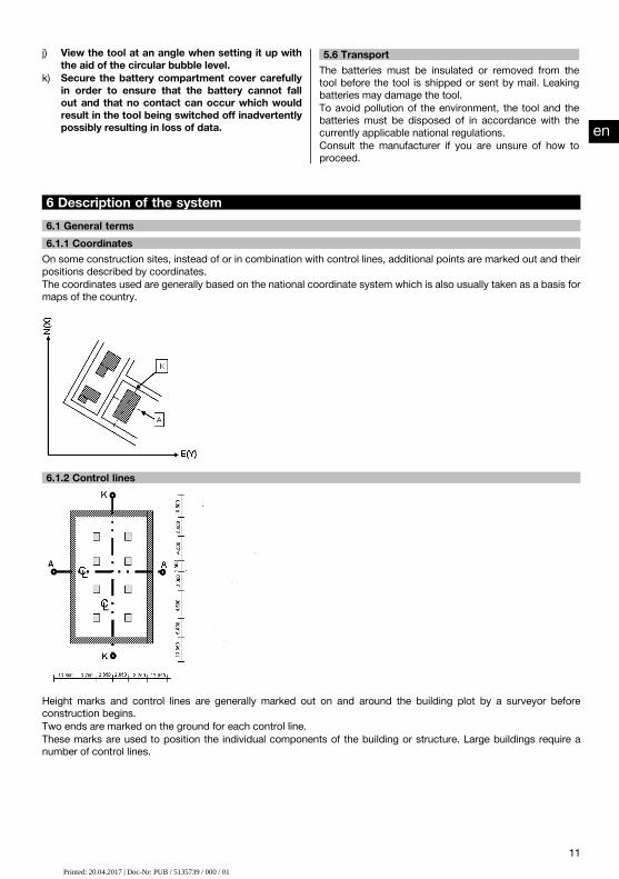
6 Description of the system6.1 General terms6.1.1 CoordinatesOn some construction sites, instead of or in combination with control lines, additional points are marked out and theirpositions described by coordinates.The coordinates used are generally based on the national coordinate system which is also usually taken as a basis formaps of the country.
6.1.2 Control lines
Height marks and control lines are generally marked out on and around the building plot by a surveyor beforeconstruction begins.Two ends are marked on the ground for each control line.These marks are used to position the individual components of the building or structure. Large buildings require anumber of control lines.
en
11Printed: 20.04.2017 | Doc-Nr: PUB / 5135739 / 000 / 00Printed: 20.04.2017 | Doc-Nr: PUB / 5135739 / 000 / 01

6.1.3 Technical termsTool axes
a Sighting axisb Vertical axisc Trunnion (tilt axis)
Horizontal circle / horizontal angle
The included angle of 70°- 40° = 30° can be calculated from the horizontal circle readings of 70° to one target and 30°to the other target.
en
12Printed: 20.04.2017 | Doc-Nr: PUB / 5135739 / 000 / 00Printed: 20.04.2017 | Doc-Nr: PUB / 5135739 / 000 / 01

Vertical circle / vertical angle
As the vertical circle is aligned at 0° to the direction of gravity or at 0° to horizontal, angles are determined relative tothe direction of gravity, so to speak.Using these values, the horizontal distance and vertical distance are calculated from the measured slope distance.
6.1.4 Telescope positions 4 3
The term “telescope position” is used to ensure that readings from the horizontal circle can be correctly assigned tothe vertical angle, i.e. the position of the telescope relative to the control panel determines in which “position” themeasurements have been taken.
When the display and the eyepiece are immediately in front of you, then the tool is in telescope position 1. 4
When the display and the objective lens are immediately in front of you, then the tool is in telescope position 2. 3
6.1.5 Terms and their descriptionSighting axis The line through the cross hairs and center of the objective lens (tele-
scope axis).Trunnion The telescope pivot (tilt) axis.Vertical axis The pivot axis of the entire tool.Zenith The zenith is the point that lies in the direction of gravity, but in the op-
posite, upward direction.Horizon The horizon is the direction perpendicular to the direction of gravity –
generally known as horizontal.Nadir Nadir is the name given to the downward direction in which gravity acts.Vertical circle The vertical circle is the circle of angles described by the telescope when
it is tilted upwards or downwards.Vertical direction A reading taken from the vertical circle is known as the vertical direction.Vertical angle (VA) A vertical angle is a reading from the vertical circle.
The vertical circle is usually aligned with the direction of gravity with theaid of the compensator, with the zero point at the zenith.
Elevation angle An elevation angle of zero refers to the horizon (horizontal plane). Positiveangles are above horizontal (upwards) and negative angles are belowhorizontal (downwards).
Horizontal circle The horizontal circle is the complete circle of angles described by thetool when it is rotated.
Horizontal direction A reading taken from the horizontal circle is known as the horizontal dir-ection.
en
13Printed: 20.04.2017 | Doc-Nr: PUB / 5135739 / 000 / 00Printed: 20.04.2017 | Doc-Nr: PUB / 5135739 / 000 / 01

Horizontal angle (HA) A horizontal angle is the difference between two readings from the ho-rizontal circle. However, a reading from one of the circles is also oftendescribed as an angle.
Slope distance (SD) Distance from the center of the telescope to the point at which the laserbeam strikes the target surface
Horizontal distance (HD) The horizontal distance derived from the measured slope distance.Alidade The rotatable center part of the total station is known as the alidade.
This part usually carries the control panel, bubble levels for leveling and,inside, the horizontal circle.
Tribrach The tool stands on the tribrach which, for example, can be mounted on atripod.The tribrach has three points of contact which can be adjusted verticallyby adjusting screws.
Tool standpoint This is the point at which the tool is set up - usually over a point markedon the ground.
Station height (Stat H) The height of the point on the ground at the tool station (above a refer-ence height).
Instrument height (HI) The height from the point on the ground or floor to the center of the tele-scope.
Reflector height (HR) The distance from the center of the reflector to the tip of the reflectorrod.
Orientation (backsight) point The target point used in conjunction with the tool station to determinethe horizontal reference direction for the horizontal angle measurement.
EDM Electronic Distance Measurer (laser distancer / range meter).East (E) In a typical surveying coordinate system this value refers to the east-
west direction.North (N) In a typical surveying coordinate system this value refers to the north-
south direction.Line (L) This is the term used to describe a longitudinal measurement along a
building control line or other reference line.Offset (O) This is the term used for a distance at right angles to a control line or
other reference line.Height (H) Many values are referred to as heights.
A height is a vertical distance from a reference point or reference surface.
6.1.6 Abbreviations and their meaningHA Horizontal angleVA Vertical angledHA Delta horizontal angledVA Delta vertical angleSD Slope distanceHD Horizontal distancedHD Delta horizontal distanceHI Instrument heightHR Reflector heightBM height Benchmark heightStat H Station heighth HeightE EastN NorthO Offsetl Line value
en
14Printed: 20.04.2017 | Doc-Nr: PUB / 5135739 / 000 / 00Printed: 20.04.2017 | Doc-Nr: PUB / 5135739 / 000 / 01

dH Delta heightdE Delta eastdN Delta northdOffs Delta offset horzdL Delta line
6.2 Angle measurement system6.2.1 Measuring principleThe tool calculates the angle in each case from two circle readings.For the purpose of distance measurement, pulses transmitted along a visible laser beam at a certain wavelength arereflected from the object to which the measurement is being taken.Distances can be determined from the values obtained from these pulses.
Tool inclination is determined with the aid of electronic levels (compensators), circle readings are corrected accordinglyand the height difference is also calculated from the measured slope distance and horizontal distance.
The built-in microprocessor system allows conversion of all distance units between the metric and imperial systems(feet, yards, inches, etc.) and digital circle graduation allows various angle units to be shown, e.g. 360° sexagesimalgraduation (° ’ ") or gon (g) in which the full circle consists of 400g graduations.
6.2.2 Dual-axis compensator 5
A compensator is, in principle, an electronic leveling system that determines exactly the remaining inclination (“offlevel”) of the axes of the total station after it has been set up.
The dual-axis compensator determines this remaining inclination of the tool with great accuracy in the line and offsetaxes.All calculations are then corrected automatically to ensure that this remaining inclination has no influence on anglemeasurements.
6.3 Distance measurement6.3.1 Distance measurement 6
Distance measurement is by way of a visible laser beam emitted through the center of the objective lens, i.e the laserdistancer is coaxial.
en
15Printed: 20.04.2017 | Doc-Nr: PUB / 5135739 / 000 / 00Printed: 20.04.2017 | Doc-Nr: PUB / 5135739 / 000 / 01

The laser beam takes measurements to “normal” surfaces without need for a special reflector.“Normal” surfaces are considered to be those that are not highly reflective. These surfaces may have a rough texture.Range depends on the reflectivity of the target surface, i.e. only slightly reflective surfaces such as those with a blue,red or green color may reduce the effective range.The tool is supplied complete with a reflector rod to which an adhesive reflective foil is attached.Taking readings from this reflector ensures reliable distance measurements even at long range.The reflector rod also allows distance measurements to be taken to points marked on the ground.
NOTECheck at regular intervals to ensure that the visible laser distancer beam is correctly adjusted and in line with thesighting axis. Send the tool to your nearest Hilti Service Center if adjustment is found necessary or if you are unsure.
6.3.2 Targets
The laser beam is capable of measuring to any stationary target.
While a distance is being measured care must be taken to ensure that no other object moves through the laser beam.
NOTEThere is otherwise a risk that the distance will be measured to another object, not to the desired target.
6.3.3 Reflector rodThe POA 50 (metric) reflector rod (consisting of four sections (each with a length of 300 mm), the rod point (length50 mm) and the reflector plate (height 100 mm or, respectively, 50 mm to the middle)) is used to take readings frompoints on the ground.The POA 51 (imperial) reflector rod (consisting of four sections (each with a length of 12" ), the rod point (length 2.03")and the reflector plate (height 3.93" or, respectively, 1.97" to the middle)) is used to take readings from points on theground.The reflector rod can be held perpendicular to the ground or floor with the aid of the built-in bubble level.In order to ensure an unobstructed line of sight for the laser beam, the distance between the tip of the rod and thecenter of the reflector can be varied.The pattern printed on the reflector foil ensures reliable measurement of distances and directions and allows a longerrange than is possible with other target surfaces.
en
16Printed: 20.04.2017 | Doc-Nr: PUB / 5135739 / 000 / 00Printed: 20.04.2017 | Doc-Nr: PUB / 5135739 / 000 / 01

Reflector rodlengths L1 L2 L3 L4 L5
POA 50 (metric) 100 mm 400 mm 700 mm 1,000 mm 1,300 mmPOA 51 (imper-ial)
4" 16" 28" 40" 52"
6.4 Height measurement6.4.1 Height measurementThe tool can be used to measure heights or differences in height.Heightmeasurements aremade using the trigonometrical heightmeasurement principle and are calculated accordingly.
The height measurements take the vertical angleand the slope distance in conjunction with the instrument heightand thereflector height into account.dH = COS(VA)*SD+HI−HR+(corr)In order to calculate the absolute height of the target point (point on the ground), the station height (Stat H) is addedto the delta height.H = Stat H + dH
en
17Printed: 20.04.2017 | Doc-Nr: PUB / 5135739 / 000 / 00Printed: 20.04.2017 | Doc-Nr: PUB / 5135739 / 000 / 01
6.5 Guide light6.5.1 Guide light 7
The guide light can be switched on or off manually and the blink frequency adjusted to one of 4 different settings.The guide light consists of two red LEDs incorporated in the telescope unit.When switched on, one of the two LEDs blinks to clearly indicate whether the person is to the right or left of thesighting line.A person at a distance of at least 10 m from the tool and standing approximately on the sighting line will see either theblinking or steady light more brightly, depending on whether they are positioned to the right or left of the sighting line.The person is positioned on the sighting line when both LEDs are seen to have the same intensity.
6.6 Laser pointer 6
The laser beam projected by the tool can also be switched on permanently.When switched on permanently, the laser beam is often referred to as a “laser pointer”.When working indoors, the laser pointer can also be used as an aiming device or, respectively, to indicate the directionin which measurements are being made.Outdoors, however, the beam is visible only under certain conditions so its use for this purpose is not really feasible.
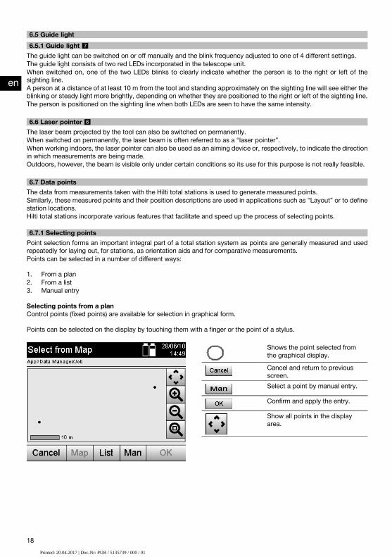
6.7 Data pointsThe data from measurements taken with the Hilti total stations is used to generate measured points.Similarly, these measured points and their position descriptions are used in applications such as “Layout” or to definestation locations.Hilti total stations incorporate various features that facilitate and speed up the process of selecting points.
6.7.1 Selecting pointsPoint selection forms an important integral part of a total station system as points are generally measured and usedrepeatedly for laying out, for stations, as orientation aids and for comparative measurements.Points can be selected in a number of different ways:
1. From a plan2. From a list3. Manual entry
Selecting points from a planControl points (fixed points) are available for selection in graphical form.
Points can be selected on the display by touching them with a finger or the point of a stylus.
Shows the point selected fromthe graphical display.Cancel and return to previousscreen.Select a point by manual entry.
Confirm and apply the entry.
Show all points in the displayarea.
en
18Printed: 20.04.2017 | Doc-Nr: PUB / 5135739 / 000 / 00Printed: 20.04.2017 | Doc-Nr: PUB / 5135739 / 000 / 01

Select a point from a list.
Zoom in.
Zoom out.
Enlarge the selected area.
NOTEPoint data assigned to a graphical element cannot be edited or deleted on the total station. This can only be doneusing Hilti PROFIS Layout.
Selecting points from a listCancel and return to previousscreen.Select a point from a plan.
Select a point by manual entry.
Confirm and apply the entry.
Manual entry of pointsCancel and return to previousscreen.Select a point from a plan.
Select a point from a list.
Confirm and apply the entry.
en
19Printed: 20.04.2017 | Doc-Nr: PUB / 5135739 / 000 / 00Printed: 20.04.2017 | Doc-Nr: PUB / 5135739 / 000 / 01

7 First steps7.1 BatteriesThe tool is equipped with two batteries which can supply power one after the other.The current state of battery charge (both batteries) is always shown.When changing batteries, one battery can remain in the tool and continue to provide power while the other battery isbeing charged.When changing batteries while the tool is in operation and to prevent the tool switching itself off, it is recommendedthat the batteries are changed one after the other.
7.2 Charging the batteryAfter unpacking the tool, remove the AC adapter, charger and battery from their holders.
Charge the battery for approx. 4 hours.
7.3 Inserting and changing the battery 8
Insert the charged battery into the tool with the battery connector underneath and facing the tool.Secure the battery compartment cover carefully.
7.4 Checking functionsNOTEPlease note that this tool makes use of friction clutches for pivoting about the alidade and thus does not have to belocked at the horizontal drives.
The horizontal and vertical drives are of the continuous type, similar to those of an optical level.Check the functions of the tool before initial use and at regular intervals in accordance with the following criteria:
1. Pivot the tool carefully by hand to the left and right and tilt the telescope up and down to check operation of thefriction clutches.
2. Turn the horizontal and vertical drives carefully in both directions.3. Turn the focussing ring fully to the left. Look through the telescope and turn the eyepiece ring to bring the cross
hairs into focus.4. With a little practice you can check the two optical sights on the telescope to ensure that they are in alignment
with the object targeted by the cross hairs.5. Check to ensure that the cover for the USB interfaces is closed securely before further use of the tool.6. Check that the screws on the carrying handle are tight.
7.5 Control panelThe control panel consists of a total of 5 buttons with symbols plus a touch screen for interactive operation.
7.5.1 Function buttonsThe function buttons are used for general operation of the tool.
Switch the tool on or off.
Switch the display backlight onor off.Select the FNC menu for addi-tional settings.Cancel or end all activefunctions and return to the startmenu.Show the help text for the cur-rent screen.
en
20Printed: 20.04.2017 | Doc-Nr: PUB / 5135739 / 000 / 00Printed: 20.04.2017 | Doc-Nr: PUB / 5135739 / 000 / 01

7.5.2 Size of the touch screenThe touch screen is approx. 74 x 56 mm (2.9 x 2.2 in) in size and has a resolution of 320 x 240 pixels.
7.5.3 Division of the touch screenThe touch screen is divided into areas for operation of the tool and for displaying information to the user.
@Instructions and info for the user
;Battery and laser pointer status indicator
=Time and date indicator and entry line
%Menu hierarchy
&Data field designations in
(
(Data fields
)Drawings to assist measuring operations
+Bar containing up to 5 touch screen buttons
7.5.4 Touch screen – numerical keyboardWhen numerical data is required to be entered, the appropriate keyboard appears in the display automatically.The keyboard layout is as shown in the illustration below.
Cancel and return to previousscreen.Confirm and apply the entry.
Move the cursor to the left.
Move the cursor to the right.
Delete the character to the leftof the cursor position. If thereis no character to the left, thecharacter at the cursor positionwill be deleted.
en
21Printed: 20.04.2017 | Doc-Nr: PUB / 5135739 / 000 / 00Printed: 20.04.2017 | Doc-Nr: PUB / 5135739 / 000 / 01

7.5.5 Touch screen – alphanumerical keyboardWhen alphanumerical data is required to be entered, the appropriate keyboard appears in the display automatically.The keyboard layout is as shown in the illustration below.
Cancel and return to previousscreen.Switch to lower case letters.
Switch to numerical keys.
Confirm and apply the entry.
Move the cursor to the left.
Move the cursor to the right.
Delete the character to the leftof the cursor position. If thereis no character to the left, thecharacter at the cursor positionwill be deleted.
7.5.6 Touch screen – general operating controlsApplication button - used to start an application or function.
Button for direct entry of numerical data, including symbols and decimalpoints.Button for direct entry of alphanumerical characters, including upper andlower cases.Select from a list. These lists may contain numerical or alphanumericalvalues and settings.A drop-down menu. In most cases, these menus provide a maximum ofthree options for the selection of settings.Example of a button in the bottom line of the display.
7.5.7 Laser pointer status indicatorThe tool is equipped with a laser pointer.
Laser pointer ON
Laser pointer OFF
7.5.8 Battery condition indicatorsThe tool uses 2 lithium-ion batteries which can supply power at the same time or one after the other, depending onrequirements.The tool switches from one battery to the other automatically.One of the batteries can thus be removed at any time, e.g. for charging, while continuing to use the tool with the otherbattery - so long as its capacity allows.
NOTEThe state of battery charge is indicated by the extent to which the battery symbol is “filled”.
en
22Printed: 20.04.2017 | Doc-Nr: PUB / 5135739 / 000 / 00Printed: 20.04.2017 | Doc-Nr: PUB / 5135739 / 000 / 01

7.6 Switching on / off7.6.1 Switching onPress and hold the on/off button for approx. 2 seconds.NOTEIf the tool is starting from a fully switched-off state, the complete start-up procedure takes approx. 20 – 30 seconds,during which two different screens are displayed consecutively.
The end of the start-up procedure has been reached when the tool shows that it requires to be leveled (see section7.7.2).
7.6.2 Switching offCancel and return to previousscreen.The total station goes into sleepmode. When the on / off but-ton is again pressed the systemgoes back into normal operatingmode and returns to the placeit was at before entering sleepmode.Switch off the total station com-pletely.
The total station will be restar-ted. Any data not already savedwill be lost.
Press the on / off button.NOTEPlease note that when switching off or restarting, the user is asked to confirm this action, just to be sure.
7.7 Setting up the tool7.7.1 Setting up over a mark on the floor or ground using the laser plummetThe tool should always be set up over a point marked on the floor or ground so that in case of measurement deviationsit is possible to fall back on the data for the station or orientation point.The tool features a laser plummet that is switched on automatically together with the tool.
7.7.2 Setting up the tool 9
1. Set up the tripod with the center of the tripod head approximately over the point marked on the ground.2. Mount the tool on the tripod by tightening the tripod screw and then switch the tool on.3. Move two of the tripod legs with your hands until the laser beam strikes the mark on the ground.
NOTE Take care to ensure that the tripod head remains approximately horizontal.4. Then press the points of the tripod legs into the ground by applying pressure with your foot.5. Adjust the footscrews to eliminate any deviation of the laser point from the mark on the ground. The laser point
must then be exactly in the center of the mark on the ground.6. The circular bubble level can be centered by adjusting the tripod legs.
NOTE This is done by extending or retracting the leg at the opposite side of the tripod, depending on the directionin which the bubble is to be moved. This process may have to be repeated several times until the desired resultis achieved.
7. Once the circular bubble level has been centered, align the laser plummet exactly with the mark on the groundby shifting the position of the tool laterally on the tripod plate.
8. Before the tool can be started, the electronic “bubble levels” must be centered by turning the footscrews so thatthe tool is reasonably level.NOTE The arrows show in which direction the tribrach footscrews require to be turned in order to center the“bubbles”.The tool can be started once this has been achieved.
en
23Printed: 20.04.2017 | Doc-Nr: PUB / 5135739 / 000 / 00Printed: 20.04.2017 | Doc-Nr: PUB / 5135739 / 000 / 01
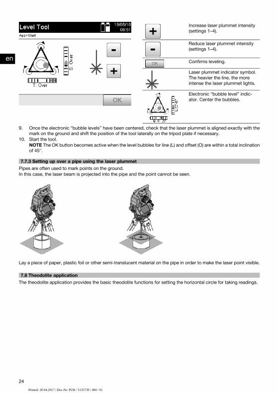
Increase laser plummet intensity(settings 1–4).
Reduce laser plummet intensity(settings 1–4).
Confirms leveling.
Laser plummet indicator symbol.The heavier the line, the moreintense the laser plummet lights.
Electronic “bubble level” indic-ator. Center the bubbles.
9. Once the electronic “bubble levels” have been centered, check that the laser plummet is aligned exactly with themark on the ground and shift the position of the tool laterally on the tripod plate if necessary.
10. Start the tool.NOTE The OK button becomes active when the level bubbles for line (L) and offset (O) are within a total inclinationof 45".
7.7.3 Setting up over a pipe using the laser plummetPipes are often used to mark points on the ground.In this case, the laser beam is projected into the pipe and the point cannot be seen.
Lay a piece of paper, plastic foil or other semi-translucent material on the pipe in order to make the laser point visible.
7.8 Theodolite applicationThe theodolite application provides the basic theodolite functions for setting the horizontal circle for taking readings.
en
24Printed: 20.04.2017 | Doc-Nr: PUB / 5135739 / 000 / 00Printed: 20.04.2017 | Doc-Nr: PUB / 5135739 / 000 / 01

Select the “Theodolite” applica-tion for setting horizontal circlereadings.
7.8.1 Setting the horizontal circle displayThe horizontal circle reading is held, the tool aimed at the new target and the circle reading then released.
Pause current horizontal circlereading.
Cancel and return to the previ-ous screen without changing thehorizontal value.Set horizontal value in the dis-play.
7.8.2 Entering a circle reading manuallyAny desired circle reading can be entered manually in any position.
en
25Printed: 20.04.2017 | Doc-Nr: PUB / 5135739 / 000 / 00Printed: 20.04.2017 | Doc-Nr: PUB / 5135739 / 000 / 01
Enter the horizontal angle valuemanually.Confirm the information shown.
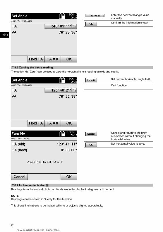
7.8.3 Zeroing the circle readingThe option Hz “Zero” can be used to zero the horizontal circle reading quickly and easily.
Set current horizontal angle to 0.
Quit function.
Cancel and return to the previ-ous screen without changing thehorizontal value.Set horizontal value to zero.
7.8.4 Inclination indicator 10
Readings from the vertical circle can be shown in the display in degrees or in percent.
NOTEReadings can be shown in % only for this function.
This allows inclinations to be measured in % or objects aligned accordingly.
en
26Printed: 20.04.2017 | Doc-Nr: PUB / 5135739 / 000 / 00Printed: 20.04.2017 | Doc-Nr: PUB / 5135739 / 000 / 01

Toggle vertical angle displaybetween degrees and %.
8 System settings8.1 ConfigurationWhen in the program menu, the configuration button is used to jump directly to the configuration button.
Return to previous view.
Select the configuration menu.
Cancel and return to previousscreen.Select the settings menu.
Show system info with serialnumber and software version.
Select display calibration.
8.1.1 SettingsSettings for angles and distances, angular resolution and for zeroing the vertical circle.
en
27Printed: 20.04.2017 | Doc-Nr: PUB / 5135739 / 000 / 00Printed: 20.04.2017 | Doc-Nr: PUB / 5135739 / 000 / 01

Cancel and return to previousscreen.Continue to the next screenwhere further settings can bemade.Exit and save settings.
Settings for automatic shut-down parameters, beep tone and language selection.
Cancel and return to previousscreen.Return to previous view.
Exit and save settings.
Possible settingsAngle units GMS (° ’ ")
GonAngle resolution 1", 5", 10"
5cc, 10cc, 20ccVA Zero Zenith
HorizonDistance Meters
US feet, Int. feet, Ft/in 1/8, Ft/in 1/16Decimal format 1000.0
1000,0Auto on/off ON
Activates the time-dependent shut-down mode. Thetool goes into sleep mode after approx. 5 min.OFFDeactivates the time-dependent shut-down mode.
Beep on/off ONActivates a signal tone when an error occurs.OFF
Language The touch screen language can be selected here.
en
28Printed: 20.04.2017 | Doc-Nr: PUB / 5135739 / 000 / 00Printed: 20.04.2017 | Doc-Nr: PUB / 5135739 / 000 / 01

8.2 Time and dateThe tool is equipped with an electronic system clock that is capable of displaying the time and date in various formats,taking the different world time zones and switching between summer and winter time into account.
Select the menu for entering thedate and time.
Entering the time and date in the following displaySelect the screen for enteringthe time zone and changingautomatically between summerand winter time.Save the values shown and re-turn to previous screen.
Cancel and return to previousscreen.Save the values shown and re-turn to previous screen.
Possible settingsTime format 12 hour
24 hourDate formats DD/MM/YY = day/month/year
MM/DD/YY = month/day/yearYY/MM/DD = year/month/day
en
29Printed: 20.04.2017 | Doc-Nr: PUB / 5135739 / 000 / 00Printed: 20.04.2017 | Doc-Nr: PUB / 5135739 / 000 / 01

Time zones GMT -12 hrs to GMT +13 hrsThe time zones are identified by capital cities.
Auto summer time ONOFF
9 Function menu (FNC)The FNC button is used to select the function menu.This menu selection can be made at any time.
Menu for entering various atmo-spheric data.Apply settings and exit from theFNC menu.
9.1 Guide light 7
The guide light can be switchedon or off and its blink frequencyadjusted (sequence: off, 1 (slow)to 4 (fast)).
en
30Printed: 20.04.2017 | Doc-Nr: PUB / 5135739 / 000 / 00Printed: 20.04.2017 | Doc-Nr: PUB / 5135739 / 000 / 01

9.2 Laser pointer 6
Switch the laser pointer on/off.
9.3 Display illuminationSwitch display illumination on/offor vary its intensity. The brighterthe display, the more power isconsumed.
9.4 Electronic bubble levelSee section 7.7.1 on setting up over a mark on the floor or ground using the laser plummet
9.5 Correction of atmospheric influencesThe tool uses a visible laser beam for distance measurement.As a fundamental principle, when light passes through the air its speed is reduced due to the density of the air.This influence varies according to the air density.Air density depends to a great extent on air pressure and air temperature and to a significantly lesser extent on airhumidity.If distances are to be measured accurately it is essential that atmospheric influences are taken into account.The tool calculates and corrects the corresponding distances automatically, but the temperature and pressure of thesurrounding air must first be entered.These parameters can be entered in various units.
en
31Printed: 20.04.2017 | Doc-Nr: PUB / 5135739 / 000 / 00Printed: 20.04.2017 | Doc-Nr: PUB / 5135739 / 000 / 01

9.5.1 Correction of atmospheric influencesMenu for entering various atmo-spheric data.
Apply settings and exit from theFNC menu.
1. Select the option “ppm”.Cancel and return to previousscreen.
2. Select the applicable units and enter the pressure and temperature.Settings for atmospheric influences and the units usedUnits (pressure) hPa
mmHgmbarinHgpsi
Units (temperature) °C°F
10 Functions required for various applications10.1 ProjectsA project has to be opened or created before the total station is used for an application.If at least one project already exists then the project selection screen will be displayed. If no project exists then thescreen for creation of a new project will be displayed.All data are assigned to the active project and saved accordingly.
10.1.1 Showing the active projectIf one or more projects are already present in memory and one of these is to be used as the active project, the projecthas to be confirmed each time an application is restarted, when another project is selected or when a new project iscreated.
en
32Printed: 20.04.2017 | Doc-Nr: PUB / 5135739 / 000 / 00Printed: 20.04.2017 | Doc-Nr: PUB / 5135739 / 000 / 01

Return to previous view.
Select or create a new project.
Confirm that the project shownis the current project.
10.1.2 Selecting a projectReturn to previous view.
Show project information.
Select or create a new project.
Confirm the selected project.
From the list shown, select the project that is to be used as the current project.
10.1.3 Creating a new projectAll data is always assigned to a project.A new project should be created when data is assigned to something new and the data is to be used only for thatpurpose.The date and time of creation are saved when a new project is created and the number of stations and points withinthe project is set to zero.
Enter project name.Cancel and return to project se-lection.Confirm and apply the entry.
NOTEAn error message is displayed when an incorrect entry is made and the user is requested to re-enter the data.
en
33Printed: 20.04.2017 | Doc-Nr: PUB / 5135739 / 000 / 00Printed: 20.04.2017 | Doc-Nr: PUB / 5135739 / 000 / 01

10.1.4 Project informationThe current status of the project is shown with the project information, e.g. date and time of creation, number ofstations and total number of the points saved.
Confirm information shown andreturn to project selection.
10.2 Setting a station and orientationPlease pay particular attention to the information given in this section.Setting a station is one of the most important operations when using a total station and must be carried out with greatcare.One of the simplest and most reliable methods of achieving this involves setting up the tool over a (known) point onthe floor or ground and using a reliable target point.The possibility of setting the station “anywhere” offers greater flexibility but presents risks in that errors may not beidentified and then transferred or multiplied as the work proceeds, etc…Moreover, this possibility requires a little experience in selecting a position for the tool relative to the reference pointsused for position calculation.
NOTEPlease remember: If the station is set incorrectly, everything measured subsequently from this station will also beincorrect – i.e. the actual applications carried out such as measuring, layouts or staking out, etc…
10.2.1 OverviewIn certain applications that make use of absolute positions, after physically setting up the tool, i.e. setting up thestation, it is also necessary to set the position of the station with the applicable data, as in the application it isnecessary to know the position at which the tool is standing.This position can be defined by way of coordinates or by establishing a building control line.This process is called Set station.In addition to the position of the tool it is also necessary to know in which direction the reference axes lie or,respectively, the direction of the main axis.In most cases where coordinates are used, the main axis runs northwards. Where control lines are used the main axislies in the direction of the control line.It is necessary to know the direction of the reference axis as the horizontal circle and its “zero mark” is, so to speak,rotated parallel to or in the direction of the main axis.This process is called Orientation.The alternative ways of setting the station can, so to speak, be used in two systems.They can be used either in a building control line system where lengths and offset distances exist or are entered, or ina perpendicular coordinate system.The station system or, respectively, the measuring system is fixed with the definition of the station.
en
34Printed: 20.04.2017 | Doc-Nr: PUB / 5135739 / 000 / 00Printed: 20.04.2017 | Doc-Nr: PUB / 5135739 / 000 / 01

4 alternative ways of setting the stationCancel and return to previousscreen.Confirm selection and continueto station identification.
NOTEThe “Set station” process always includes setting a position and an orientation.
When one of the four applications is started, such as Horizontal Layout, Vertical Layout, As-Built or Measure andRecord, a station and orientation always have to be set.If, in addition, heights are also to be used, i.e. target heights are to be determined or laid out, the height of the centerof the telescope must also be defined.
Summary of alternatives for setting the station (6 options)Heights On, off
This setting determines whether heights are to be cal-culated or shown.
Point system Building control lineManually enter data that refers to the building controlline (along the line or offset).Coord / GraphUse coordinates or graphic data from the plan / CAD.
Setup location Over PtThe tool station is located over a point with a markedand known position.“Anywhere”The tool station can be set “anywhere”. The position ofthe station must be measured or calculated from meas-urement data.
10.2.2 Setting a station over a point with control linesThe dimensions or position description of many parts of a structure are given in relation to a building control line onthe plan.With the total station, building control lines and their corresponding dimensions can also be used.
en
35Printed: 20.04.2017 | Doc-Nr: PUB / 5135739 / 000 / 00Printed: 20.04.2017 | Doc-Nr: PUB / 5135739 / 000 / 01

Cancel and return to previousscreen.Confirm selection and continueto station identification.
Setting up the tool over a point on a building control lineThe tool is set up over a point marked on the building control line, from which the points or items to be measured areeasily visible.Special care must be taken to ensure that the tripod stands steadily and securely.
The position of the tool P0 and the orientation point P1 lie on a common building control line.
10.2.2.1 Entering the station positionA unique designation that clearly identifies the station or tool position must be entered as a unique designation isnecessary for saving the station data.
Enter station names.
Return to previous view.
Confirm entry of station data andcontinue with orientation.
en
36Printed: 20.04.2017 | Doc-Nr: PUB / 5135739 / 000 / 00Printed: 20.04.2017 | Doc-Nr: PUB / 5135739 / 000 / 01

10.2.2.2 Entering the target pointA designation that clearly identifies the orientation point must be entered when data is saved.
Enter name for the orientationpoint.Return to previous view.
Continue to “Orientation meas-urement”.Measure angle and distance.Continue, showing the(re)calculated station height.
After the orientation point has been entered, a reading must be taken from the orientation point. When dong so, theorientation point must be targeted as accurately as possible.
10.2.2.3 Setting a station with a control lineThe station is set immediately after the angle measurement for orientation purposes.
Return to orientation measure-ment.Show station data.
Setting the station.
NOTEThe station is always saved in internal memory. If the station name already exists in memory, the station must berenamed. i.e. a new name assigned to it.
After the station has been set, the user can continue with the actual main application previously selected.
10.2.2.4 Shift and rotate axisShift axisThe axis starting point can be shifted in order to use a different reference point as the origin of the coordinate system.If the value entered is positive, the axis is moved forward. If it is negative, the axis is moved back. A positive valueshifts the starting point to the right and a negative value shifts it to the left.
en
37Printed: 20.04.2017 | Doc-Nr: PUB / 5135739 / 000 / 00Printed: 20.04.2017 | Doc-Nr: PUB / 5135739 / 000 / 01

Return to previous view.
Enter axis shift manually.
Take measurement to point. Theaxis, distance and height valuesare shown. The values can beindividually labeled.Rotate axis.
Continue to the next step.
Rotating the axisThe axis bearing (direction) can be rotated about the starting point. If the value entered is positive, the axis is rotatedclockwise. If it is negative, the axis is rotated counterclockwise.
Return to previous view.
Confirm rotation.
After the station has been set, the user can continue with the actual main application previously selected.
10.2.3 Setting a station “anywhere”, with building control linesSetting the station “anywhere” allows the position of the station to be defined by measuring the angles and distancesto two reference points.The ability to set the station “anywhere” is used when it is not possible to set it at a point on the building control lineor when the line of sight to the points to be measured is obstructed.Extra care must be taken when setting the station “anywhere”.Additional measurements are taken in order to set the station “anywhere”. Additional measurements always present arisk of errors.Care must also be taken to ensure that the geometry of the situation allows a usable position to be achieved.The tool checks the basic geometric relationships in order to ensure that a usable position can be calculated andissues a warning in critical situations.Nevertheless, the user of the tool is obliged to exercise special caution in this respect as the software is not capableof recognizing all potentially critical situations.
en
38Printed: 20.04.2017 | Doc-Nr: PUB / 5135739 / 000 / 00Printed: 20.04.2017 | Doc-Nr: PUB / 5135739 / 000 / 01
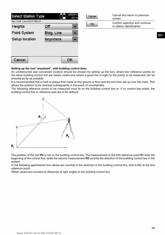
Cancel and return to previousscreen.Confirm selection and continueto station identification.
Setting up the tool “anywhere”, with building control linesAn unobstructed and convenient location should be chosen for setting up the tool, where two reference points onthe same building control line are clearly visible and where a good line of sight to the points to be measured can beensured as far as possible.It is recommended that a mark is always first made on the ground or floor and the tool then set up over this mark. Thisallows the position to be checked subsequently in the event of uncertainties.The following reference points to be measured must lie on the building control line or, if no control line exists, thebuilding control line or reference axis are to be defined.
The position of the tool P0 is not on the building control line. The measurement to the first reference point P1 fixes thebeginning of the control line, while the second measurement P2 records the direction of the building control line in thesystem.In the following applications line values are counted in the direction of the building control line, with 0.000 at the firstreference point.Offset values are counted as distances at right angles to the building control line.
en
39Printed: 20.04.2017 | Doc-Nr: PUB / 5135739 / 000 / 00Printed: 20.04.2017 | Doc-Nr: PUB / 5135739 / 000 / 01

10.2.3.1 Measuring to the first reference point on a control lineEnter the name of the orientationpoint.Return to previous view.
Measure angle and distance.
Continue to “Measure to thesecond reference point”.
10.2.3.2 Measuring to the second reference pointReturn to “Measuring to the firstreference point”.
Measure angle and distance.
Continue to “Set station”.
Checking the distance betweenreference points
Continue by checking the distance between the station and the orientation point, as described in the applicablesection.
10.2.3.3 Set stationThe station is set immediately after the angle measurement for orientation purposes.
Alphanumerical field for entry ofstation name.Return to previous view.
Show station data.
Setting the station.
NOTEThe station is always saved in internal memory. If the station name already exists in memory, the station must berenamed. i.e. a new name assigned to it.
en
40Printed: 20.04.2017 | Doc-Nr: PUB / 5135739 / 000 / 00Printed: 20.04.2017 | Doc-Nr: PUB / 5135739 / 000 / 01

Continue with rotating the axis and shifting the axis as described in the applicable sections.
10.2.4 Setting a station over a point with coordinatesOn many construction sites, measured points with coordinates already exist, or the positions of parts of the structure,building control lines or foundations etc. are already described with coordinates.In this case, the decision about whether coordinates or building control lines are to be used can be taken when thestation is being set up.
Cancel and return to previousscreen.Confirm selection and continueto station identification.
Setting up the tool over a point with coordinatesThe tool is set up over a point marked on the floor or ground, the position of which is defined by coordinates and fromwhich the points or items to be measured are easily visible.Special care must be taken to ensure that the tripod stands steadily and securely.
The tool is positioned at a point defined by coordinates P0 and, for the purpose of orientation, is aimed at anotherpoint defined by coordinates P1.The tool calculates the position within the coordinate system.For better identification of the orientation point, the distance can be measured and compared with the coordinates.
NOTEThis makes correct identification of the orientation point more reliable. If the coordinate point P0 also has a height,this will first be used as the station height. The height of the station can be redetermined and changed at any timebefore the station is set finally.
The orientation point is decisive for correct calculation of direction and should therefore be selected and measuredwith care.
10.2.4.1 Entering the position of the stationA designation that identifies the station or tool position clearly and uniquely must be entered. The coordinates of itsposition must belong to this designation.i.e. the station point may already exist as a saved point in the job or, alternatively, the coordinates will have to beentered manually.
en
41Printed: 20.04.2017 | Doc-Nr: PUB / 5135739 / 000 / 00Printed: 20.04.2017 | Doc-Nr: PUB / 5135739 / 000 / 01

Enter station names.
Return to previous view.
Confirm entry of station data andcontinue with orientation.
After the name for the station point has been entered, the corresponding coordinates or positions are searched for inthe graphics data in memory.If no point data exists under the given name the coordinates have to be entered manually.
10.2.4.2 Entering the target pointA designation that identifies the target point clearly and uniquely must be entered. The coordinates of its position mustbelong to this designation.The target point must exist as a saved point in the job or, alternatively, the coordinates have to be entered manually.
Enter the name of the orientationpoint.Return to previous view.
Check distance between the sta-tion and orientation point.Continue to “Set station”.
Measure angle and distance.
NOTEWhen the name for the orientation point is entered, the corresponding coordinates or position are searched for in thegraphics data saved in memory. If no point data exists under this name the coordinates have to be entered manually.
Optional check of distance between the station and the orientation pointAfter the target point has been entered, this point must be sighted exactly for the purpose of a reference measurement.After measuring the distance to the orientation point, you have the option of checking the distance between the stationand the orientation point.This serves as an aid for checking correct point selection and correct sighting of this point, and shows how well themeasured distance corresponds to the distance measured from the coordinates.
en
42Printed: 20.04.2017 | Doc-Nr: PUB / 5135739 / 000 / 00Printed: 20.04.2017 | Doc-Nr: PUB / 5135739 / 000 / 01

Return to previous view.
Continue to the next screenwhere further settings can bemade.
The dHD value shown is the difference between the measured distance and the distance calculated from thecoordinates.Further points can be checked by pressing the “Next” button. In addition to the dHD, the dHA value (which is thedifference between the measured horizontal angle and the horizontal angle calculated from the coordinates) is alsoshown in the display.
10.2.4.3 Set stationThe station is always saved in internal memory.If the station name already exists in memory, the station must be renamed. i.e. a new name assigned to it.
For entering station names.
Return to orientation measure-ment.Show station data.
Setting the station.
10.2.5 Setting a station “anywhere”, with coordinatesSetting the station “anywhere” allows the position of the station to be defined by measuring the angles and distancesto two reference points.The ability to set the station “anywhere” is used when it is not possible to set it at a point on the building control lineor when the line of sight to the points to be measured is obstructed.Extra care must be taken when setting the station “anywhere”.Additional measurements are taken in order to set the station “anywhere”. Additional measurements always present arisk of errors.Care must also be taken to ensure that the geometry of the situation allows a usable position to be achieved.The tool checks the basic geometric relationships in order to ensure that a usable position can be calculated andissues a warning in critical situations.Nevertheless, the user of the tool is obliged to exercise special caution in this respect as the software is not capableof recognizing all potentially critical situations.
en
43Printed: 20.04.2017 | Doc-Nr: PUB / 5135739 / 000 / 00Printed: 20.04.2017 | Doc-Nr: PUB / 5135739 / 000 / 01
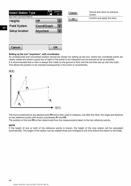
Cancel and return to previousscreen.Confirm and apply the entry.
Setting up the tool “anywhere”, with coordinatesAn unobstructed and convenient location should be chosen for setting up the tool, where two coordinate points areclearly visible and where a good line of sight to the points to be measured can be ensured as far as possible.It is recommended that a mark is always first made on the ground or floor and the tool then set up over this mark.This allows the position to be checked subsequently in the event of uncertainties.
The tool is positioned at any desired point P0 and is then used to measure, one after the other, the angle and distanceto two reference points with known coordinates P1 and P2.The position of the tool P0 is then determined from the measurements taken to the two reference points.
NOTEIf the height of one or both of the reference points is known, the height of the new station will be calculatedautomatically. The height of the station can be redetermined and changed at any time before the station is set finally.
en
44Printed: 20.04.2017 | Doc-Nr: PUB / 5135739 / 000 / 00Printed: 20.04.2017 | Doc-Nr: PUB / 5135739 / 000 / 01

10.2.5.1 Measuring to the first reference pointEnter the name of the orientationpoint.Return to previous view.
Measure angle and distance.
Continue to “Measure to thesecond reference point”.
Corresponding coordinates or positions are searched for in the graphic data saved in the system.If no point data exists under this name the coordinates have to be entered manually.
10.2.5.2 Measuring to the second reference pointReturn to “Measuring to the firstreference point”.
Measure angle and distance.
Continue to “Set station”.
Checking the distance betweenreference points
Continue by checking the distance between the station and the orientation point, as described in the applicablesection.
10.2.5.3 Set stationThe station is always saved in internal memory.If the station name already exists in memory, the station must be renamed. i.e. a new name assigned to it.
For entering station names.
Return to orientation measure-ment.Show station data.
Setting the station.
en
45Printed: 20.04.2017 | Doc-Nr: PUB / 5135739 / 000 / 00Printed: 20.04.2017 | Doc-Nr: PUB / 5135739 / 000 / 01

10.3 Setting the heightIf heights are also to be used in addition to setting the station and orientation, i.e. target heights are to be determinedor laid out, the height of the center of the telescope must also be defined.Two different methods can be used to set the height:
1. If the height of the point on the floor or ground is known, the height of the tool is then measured. The height ofthe center of the telescope is the sum of these two values.
2. Alternatively, an angle and distance measurement can be made to a point or mark with a known height and thusby “measuring” in this way, the height of the center of the telescope determined and transferred back to the tool.
10.3.1 Setting a station with a control line (height option “on”)If the “With heights” option has been selected, the station heights will be shown in the “Set station” screen.These can be confirmed or redefined.
Defining a new station heightStation height can be defined in two different ways:
1. Direct manual entry of the station height.2. The station height is defined by manually entering the height of a height mark and by measuring the vertical angle
and distance.
Return to previous view.
Enter station height manually ormeasure to a height mark.Confirm station height. Continuewith setting station.
1st Direct manual entry of the station heightAfter the option for redefinition of the station height has been selected from the previous screen, the new station heightcan be entered manually here.
Cancel and return to previousscreen.Confirm station height. Continuewith setting station.
2nd Definition of the station height by entering a height and measuring the vertical angle and distanceThe station height is transferred “back” to the station from the height mark, so to speak, by entering the referenceheight, tool height and reflector height in conjunction with a vertical angle and distance measurement.When doing this it is essential that the correct tool height and reflector height are entered.
en
46Printed: 20.04.2017 | Doc-Nr: PUB / 5135739 / 000 / 00Printed: 20.04.2017 | Doc-Nr: PUB / 5135739 / 000 / 01

Cancel and return to previousscreen.Measure angle and distance.Continue, showing the(re)calculated station height.
Showing the recalculated station height after measurementThe recalculated station height is shown after taking the angle and distance measurements and it can then beconfirmed or canceled.
Cancel and return to previousscreen.Confirm station height. Continuewith setting station.
Set stationReturn to orientation measure-ment.Enter station height or heightmark manually or, respectively,select a previously saved heightpoint with measurement of ver-tical angle and distance.Show station data.
Setting the station.
NOTEWhen the “Heights” option is active, a height must be assigned to the station, i.e. a height value for the station mustexist.
NOTEThe station is always saved in the system’s internal memory. If the station name already exists in memory, the stationmust be renamed. i.e. a new name assigned to it.
en
47Printed: 20.04.2017 | Doc-Nr: PUB / 5135739 / 000 / 00Printed: 20.04.2017 | Doc-Nr: PUB / 5135739 / 000 / 01

After the station has been set, the user can continue with the actual main application previously selected.
10.3.2 Setting a station with coordinates (height option “on”)Defining a new station heightThe station height can be determined in three different ways:
Direct manual entry of the station heightThe station height is determined by manually entering the height of a height mark and by measuring the verticalangle and distance.Definition of the station height by selecting a point with heights from data memory and measurement of thevertical angle and distance to this point
Return to previous view.
Determine new station heightwith saved point.Enter station height manually ormeasure to a height mark.Confirm and apply the entry.
1st Direct manual entry of the station heightAfter the option for redefinition of the station height has been selected from the previous screen, the new station heightcan be entered manually here.
Cancel and return to previousscreen.Setting the station.
2nd Definition of the station height by entering a height and measuring the vertical angle and distanceThe station height is transferred “back” to the station from the height mark, so to speak, by entering the referenceheight, tool height and reflector height in conjunction with a vertical angle and distance measurement.When doing this it is essential that the correct tool height and reflector height are entered.
en
48Printed: 20.04.2017 | Doc-Nr: PUB / 5135739 / 000 / 00Printed: 20.04.2017 | Doc-Nr: PUB / 5135739 / 000 / 01

Cancel and return to previousscreen.Measure angle and distance.Continue, showing the(re)calculated station height.
Showing the recalculated station height after measurementThe recalculated station height is shown after taking the angle and distance measurements and it can then beconfirmed or canceled.
Cancel and return to previousscreen.Setting the station.
3. Definition of the station height by selecting a point with heights from data memory and measurement of thevertical angle and distanceThe station height is transferred “back” to the station from the height point or height mark, so to speak, by enteringthe height point, the tool height and reflector height in conjunction with a vertical angle and distance measurement.When doing this it is essential that the correct tool height and reflector height are entered.
Enter height point name.
Cancel and return to previousscreen.Measure angle and distance.Continue, showing the(re)calculated station height.
Corresponding coordinates or positions are searched for in the graphical data saved in the system.If no point data exists under this name the coordinates have to be entered manually.
en
49Printed: 20.04.2017 | Doc-Nr: PUB / 5135739 / 000 / 00Printed: 20.04.2017 | Doc-Nr: PUB / 5135739 / 000 / 01

Showing the recalculated station height after measurementThe recalculated station height is shown after taking the angle and distance measurements and it can then beconfirmed or canceled.
Cancel and return to previousscreen.Setting the station.
Set stationIf the “With heights” option has been selected, the station heights will be shown in the “Set station” screen.These can be confirmed or redefined.
Return to orientation measure-ment.Enter station height or heightmark manually or, respectively,select a previously saved heightpoint with measurement of ver-tical angle and distance.Show station data.
Setting the station.
NOTEWhen the “Heights” option is active, a height must be assigned to the station, i.e. a height value must exist. If nostation height is given, an error message is displayed and the user is instructed to determine the station height.
11 Applications11.1 Horizontal layout (Horz. layout)11.1.1 The horizontal layout principleThe layout operation is used to transfer data from the plan to the actual object or building plot.This plan data consists either of dimensions that relate to building control lines or positions described by coordinates.The plan data or layout positions can be entered as dimensions or distances, as coordinates or can be transferredpreviously from a PC.In addition, plan data in the form of CAD drawings can be transferred to the total station and the applicable graphicalpoints for the layout then selected from the display of the tool.This makes working with long numbers or lots of numbers unnecessary.
en
50Printed: 20.04.2017 | Doc-Nr: PUB / 5135739 / 000 / 00Printed: 20.04.2017 | Doc-Nr: PUB / 5135739 / 000 / 01

The “Horizontal Layout” application is started by way of the corresponding button in the in the application menu.
Return to previous view.
Continue to “Select further ap-plications”.Select the “Horizontal layout”application.
After starting the application, the projects or list of projects (see section 13.2) is shown for selection as well as thecorresponding station selection or station setup.The “Horizontal layout” application begins after station setup is completed.Depending on the station selected, there are two alternative methods for determining the point to be laid out:
1. Laying out points using building control lines2. Laying out points using coordinates and/or points based on a CAD drawing
11.1.2 Laying out with building control linesWhen laying out with control lines, the layout values to be entered always refer to the building control line that hasbeen selected as the reference axis.
Entering layout points relative to the building control lineEnter the layout point as a dimension relative to the building control line defined when the station was set or,respectively, the building control line on which the tool is set up.The values to be entered are line and offset distances relative to the previously defined building control line.
en
51Printed: 20.04.2017 | Doc-Nr: PUB / 5135739 / 000 / 00Printed: 20.04.2017 | Doc-Nr: PUB / 5135739 / 000 / 01

Return to previous view.
Confirm entry and continue,showing display for aligning thetool with the point to be stakedor marked out.
NOTELayout values on the building control line in a forwards or backwards direction from the tool station are line (longitudinal)values and those to the right or left of the building control line are offset values. Forwards and to the right are positivevalues, backwards and to the left are negative values.
Direction to the layout pointUsing this screen, the tool is aimed at the point to be laid out by rotating the tool until the red direction indicator isat the zero position and, below this, the numerical display for angle difference shows a value as close as possible tozero. The cross hairs are then aimed at the point to be laid out and the reflector bearer can be guided into position.Alternatively, the reflector bearer can bring himself into position on the sighting line with the aid of the guide light.
Return to entry of layout values.
Measure distance and continue,showing layout corrections.
en
52Printed: 20.04.2017 | Doc-Nr: PUB / 5135739 / 000 / 00Printed: 20.04.2017 | Doc-Nr: PUB / 5135739 / 000 / 01

P0 is the position of the tool after setting up.P1 is the point to be laid out and the tool is already aimed at this point.The reflector bearer is standing close to the point (distance) calculated.After each distance measurement the tool indicates the amount by which the reflector bearer must move, forwards orbackwards, towards the point to be laid out.
Layout corrections after distance measurementsAfter the distance measurement has been taken, the reflector bearer is guided with the aid of the corrections Fwd,Back, Left, Right, Up and Down.When measurements show that the reflector bearer is exactly on the sighting line, the Right / Left correction in thedisplay shows a value of 0.000 m (0.00 ft).
Return to entry of layout values.
Show and save the result.
Measure distance and updatelayout corrections.Enter the next point.
P0 is the position of the tool after setting up.When measurements are taken to a reflector position not exactly in the direction of the new point, the correspondingFwd, Back, Left, Right corrections to the new point P1 are displayed.
Overview of the direction instructions to the layout point starting from the last measured target pointFwd The reflector bearer must move closer to the tool by the
amount indicated.Back The reflector bearer must move further away from the
tool by the amount indicated.Left The reflector bearer must move further to the left, as
seen from the tool, by the amount indicated.Right The reflector bearer must move further to the right, as
seen from the tool, by the amount indicated.
en
53Printed: 20.04.2017 | Doc-Nr: PUB / 5135739 / 000 / 00Printed: 20.04.2017 | Doc-Nr: PUB / 5135739 / 000 / 01

Up The tip of the reflector must be moved upwards by theamount indicated.
Down The tip of the reflector must be moved downwards bythe amount indicated.
Layout resultsScreen showing the layout differences in terms of line, offset and height based on the last target point measurement.
Return to entry of layout values.
Save the layout values and lastdifferences.Enter the next point.
NOTEIf the option to include heights was not set when the station was set up, height values and all associated informationare not displayed.
Saving layout data with building control linesPt ID Name of layout point.Line (entered) Line distance entered relative to the building control
line.Offset (entered) Offset distance entered relative to the building control
line.Height (entered) Height entered.Line distance (measured) Line distance measured relative to the building control
line.Offset (measured) Offset distance measured relative to the building con-
trol line.Height (measured) Measured height.dO Difference in offset value based on the building control
line. dO = offset (measured) – offset (entered)dL Difference in line value based on the building control
line. dL = line (measured) – line (entered)dH Difference in height. dH = height (measured) – height
(entered)
11.1.3 Laying out with coordinatesEntering the layout pointsThe layout values with point coordinates can be entered in three different ways:
1. Manual entry of point coordinates.2. Selection of point coordinates from a list of points saved in memory.3. Selection of point coordinates from a CAD drawing with points saved in memory.
en
54Printed: 20.04.2017 | Doc-Nr: PUB / 5135739 / 000 / 00Printed: 20.04.2017 | Doc-Nr: PUB / 5135739 / 000 / 01

Return to previous view.
Confirm entry and continue,showing display for aligning thetool with the point to be stakedor marked out.
Entering the layout points (from a CAD drawing)The layout points are selected directly from a CAD drawing.With this method, the point is already incorporated in the drawing as a three-dimensional or two-dimensional pointand can be extracted accordingly.
Shows the point selected fromthe graphical display.Cancel and return to entry oflayout points.Select a point from a plan.
Select a point from a list.
Enter coordinates manually.
Confirm the selected point.
NOTEIf the option to exclude heights is activated when setting up the station, height values and all associated informationare not displayed. The other screens shown are the same as described in the previous section.
P0 is the position of the tool after setting up.P1 is the point described by coordinates. After the tool has been lined up (aimed), the reflector bearer goes to theapproximate distance calculated.
en
55Printed: 20.04.2017 | Doc-Nr: PUB / 5135739 / 000 / 00Printed: 20.04.2017 | Doc-Nr: PUB / 5135739 / 000 / 01

After each distance measurement the tool indicates the amount by which the reflector bearer must move towards thepoint to be laid out.
Layout results with coordinatesShows the layout difference in terms of coordinates based on the last distance and angle measurements.
Return to entry of layout values.
Save the layout values and lastdifferences.Enter the next point.
P0 is the position of the tool after setting up.When measurements are taken to a reflector position not exactly in the direction of the new point, the correspondingFwd, Back, Left, Right directions to the new point P1 are displayed.
Saving data for staking out with coordinatesPt ID Name of layout point.Northings (entered) The northings entered refer to the coordinate reference
system.Height (entered) Height entered.Eastings (entered) The eastings entered refer to the coordinate reference
system.Northings (measured) Measured northings refer to the coordinate reference
system.Height (measured) Measured height.Eastings (measured) Measured eastings refer to the coordinate reference
system.dN Difference in northing based on the coordinate refer-
ence system. dN = delta north (measured) – delta north(entered)
en
56Printed: 20.04.2017 | Doc-Nr: PUB / 5135739 / 000 / 00Printed: 20.04.2017 | Doc-Nr: PUB / 5135739 / 000 / 01

dH Difference in height. dH = height (measured) – height(entered)
dE Difference in coordinate easting based on the coordin-ate reference system. dE = delta east (measured) –delta east (entered)
NOTEThe procedure for a horizontal layout with coordinates is the same as for a layout based on a building control line,with the exception that coordinates or coordinate differences are entered or shown as results instead of line or offsetdistances.
11.2 Vertical layout (Vert. layout)11.2.1 The vertical layout principleIn a vertical layout, plan data is transferred to a vertical reference plane such as a wall or facade, etc.This plan data is either in the form of dimensions that relate to the building control line in the vertical reference planeor positions described by coordinates in a vertical reference plane.The plan data or layout positions in the form of dimensions or distances can be entered with coordinates or can betransferred previously from a PC.In addition, plan data in the form of CAD drawings can be transferred to the total station and the applicable graphicalpoints for the layout then selected from the display of the tool.This makes working with long numbers or lots of numbers unnecessary.Typical applications are the positioning of fastening points on facades, installation channels on walls, pipes, etc.A special application offers the possibility of comparing a vertical surface with a theoretically absolutely flat surface inorder to check for unevenness or, respectively, to produce a record of the results.
The “Vertical layout” application can be started with the corresponding button in the in the application menu.
en
57Printed: 20.04.2017 | Doc-Nr: PUB / 5135739 / 000 / 00Printed: 20.04.2017 | Doc-Nr: PUB / 5135739 / 000 / 01

Return to previous view.
Continue to “Select further ap-plications”.Select the “Vertical layout” ap-plication.
After starting the application, the projects or list of projects is shown for selection as well as the corresponding stationselection or station setup.The “Vertical layout” application begins after station setup is completed.Depending on the station selected, there are two alternative methods for determining the point to be laid out:
1. Laying out points with building control lines, i.e. control lines in the vertical reference plane.2. Laying out points with coordinates or points based on a CAD drawing
11.2.2 Vertical layout with building control linesIn a vertical layout with building control lines the control lines are defined by measuring to two reference points whenthe station is set up.
Setting up the stationThe station should be set up in front of the vertical plane in a position that is as central as possible and at a distancethat allows as clear a view as possible of all points.The zero point (1) of the reference axis system and the direction (2) of the vertical reference plane are defined whenthe tool is set up.
CautionThe reference point (1) is the decisive point. The vertical and horizontal reference axes in the vertical reference planeare set on this point.
An optimum setup or, respectively, tool position has been achieved when the ratio between the horizontal referencelength L and the distance Q is L : Q = 25 : 10 to 7 : 10, so that the included angle lies between α = 40° - 100°.
en
58Printed: 20.04.2017 | Doc-Nr: PUB / 5135739 / 000 / 00Printed: 20.04.2017 | Doc-Nr: PUB / 5135739 / 000 / 01

NOTEThe procedure for setting up the station is the same as for setting up the station “anywhere” with building controllines, with the difference that the first reference point is set at the zero point of the building control line system in thevertical plane and the second reference point defines the direction of the vertical plane relative to the tool system. Inany case, the horizontal and vertical control lines are adopted from point (1).
Shifting a control lineIn order to shift the control line system or, respectively, the “zero point” on the vertical reference plane, shift valuesrequire to be entered.These shift values can be used to shift the zero point of the control line system to the left (-) and right (+) horizontally,up (+) and down (-) vertically, and the entire plane forwards (+) and backwards (-).It can be necessary to shift a control line when the “zero point” cannot be sighted directly as the first reference point.An existing reference point than has to be used and then shifted onto a control line by entering the applicable shiftvalues (distances).
Cancel and return to previousscreen.Confirm entry and continue withentry of layout values.
Entering a layout positionThe layout value is entered as a dimension relative to the reference axis or building control line in the vertical planethat was defined when the station was set up.
Cancel and return to the startmenu.Enter reference plane shifts.
Confirm entry and continue,showing display for aligning thetool with the point to be stakedor marked out.
Direction to the layout pointUsing this screen, the tool is aimed at the point to be laid out by rotating the tool until the red direction indicator shows“zero”.The cross hairs are them aimed in the direction of the point to be laid out.The telescope can then be moved vertically until both triangles are shown as unfilled outlines.
NOTEIf the upper triangle is solid - move the telescope downwards. If the upper triangle is solid - move the telescopedownwards.
en
59Printed: 20.04.2017 | Doc-Nr: PUB / 5135739 / 000 / 00Printed: 20.04.2017 | Doc-Nr: PUB / 5135739 / 000 / 01

Where possible, the person holding the rod can move into position on the sighting line with the aid of the guide light.
Return to entry of layout values.
Measure distance and continue,showing layout corrections.
Layout correctionsUsing the corrections displayed, the target bearer or target is guided Up, Down, Left, Right into position.With the aid of distance measurement, a correction Forward or Back can also be made.The corrections shown are updated after each distance measurement until, step by step, the final position is reached.
Return to entry of layout values.
Show and save the result.
Measure distance and updatelayout corrections.Enter the next point.
Instructions displayed concerning movement of the target to which measurements are taken.Fwd The target must be moved further toward the reference
plane.Back The target must be moved further away from the refer-
ence plane.Left The target must be moved further to the left, as seen
from the tool, by the amount indicated.Right The target must be moved further to the right, as seen
from the tool, by the amount indicated.Up The target must be moved further up, as seen from the
tool, by the amount indicated.Down The target must be moved further down, as seen from
the tool, by the amount indicated.
Layout resultsShows the layout difference in terms of line, height and offset based on the last distance and angle measurements.
en
60Printed: 20.04.2017 | Doc-Nr: PUB / 5135739 / 000 / 00Printed: 20.04.2017 | Doc-Nr: PUB / 5135739 / 000 / 01

Return to entry of layout values.
Save the layout values and lastdifferences.Enter the next point.
Saving data for staking out with building control linesPt ID Name of layout point.Line (entered) Line distance entered, relative to the reference axis.Height (entered) Height entered.Offset (entered) Vertical offset entered, relative to the reference plane.Line distance (measured) Line distance measured, relative to the reference axis.Height (measured) Measured height.Offset (measured) Offset measured relative to the reference plane.dL Difference in line value based on the reference axis.
dL = line (measured) – line (entered)dH Difference in height. dH = height (measured) – height
(entered)dOffs Difference in offset value based on the reference axis.
dO = offset (measured) – offset (entered)
11.2.3 Vertical layout with coordinatesCoordinates can be used, for example, when coordinates are available as reference points and points in the verticalplane are also available as coordinates in the same system.This is the case, for example, when points in the vertical plane have been measured previously using coordinates.
Entering the layout pointsThree different methods can be used to enter layout values with point coordinates:
1. Manual entry of point coordinates.2. Selection of point coordinates from a list of points saved in memory.3. Selection of point coordinates from a CAD drawing with points saved in memory.
Cancel and return to the startmenu.Confirm entry and continue,showing display for aligning thetool with the point to be stakedor marked out.
en
61Printed: 20.04.2017 | Doc-Nr: PUB / 5135739 / 000 / 00Printed: 20.04.2017 | Doc-Nr: PUB / 5135739 / 000 / 01
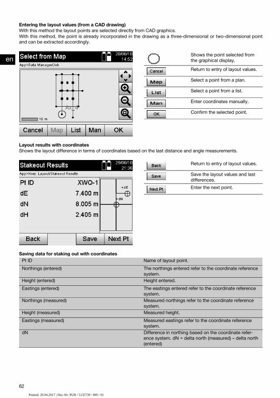
Entering the layout values (from a CAD drawing)With this method the layout points are selected directly from CAD graphics.With this method, the point is already incorporated in the drawing as a three-dimensional or two-dimensional pointand can be extracted accordingly.
Shows the point selected fromthe graphical display.Return to entry of layout values.
Select a point from a plan.
Select a point from a list.
Enter coordinates manually.
Confirm the selected point.
Layout results with coordinatesShows the layout difference in terms of coordinates based on the last distance and angle measurements.
Return to entry of layout values.
Save the layout values and lastdifferences.Enter the next point.
Saving data for staking out with coordinatesPt ID Name of layout point.Northings (entered) The northings entered refer to the coordinate reference
system.Height (entered) Height entered.Eastings (entered) The eastings entered refer to the coordinate reference
system.Northings (measured) Measured northings refer to the coordinate reference
system.Height (measured) Measured height.Eastings (measured) Measured eastings refer to the coordinate reference
system.dN Difference in northing based on the coordinate refer-
ence system. dN = delta north (measured) – delta north(entered)
en
62Printed: 20.04.2017 | Doc-Nr: PUB / 5135739 / 000 / 00Printed: 20.04.2017 | Doc-Nr: PUB / 5135739 / 000 / 01

dH Difference in height. dH = height (measured) – height(entered)
dE Difference in coordinate easting based on the coordin-ate reference system. dE = delta east (measured) –delta east (entered)
NOTEThe vertical layout always uses three-dimensional point descriptions. In layouts with control lines and layouts withcoordinates, the line, height and offset dimensions are used.
NOTEThe other screens shown are the same as described in the previous section.
11.3 As-built11.3.1 The principle of “As-built”In principle, as-built measurements can be regarded as a reversal of the horizontal layout application.With as-built, existing positions are compared with their positions on the plan and the deviations shown and recordedaccordingly.Depending on how the station has been set up, the plan data or, respectively, the positions to be compared, can takethe form of dimensions, coordinates or points in graphics.When plan data in the form of CAD drawings can be transferred from a PC to the total station and the applicablegraphical points then selected from the display of the tool, so working with long numbers or lots of numbers is nolonger necessary.Typical applications are checking walls, columns, formwork, large openings and much more. These jobs are doneby comparing positions on the plan with actual points on the object and displaying or, respectively, recording thedifferences.
The “As-built” application is started by way of the corresponding button in the in the application menu.
Return to previous view.
Continue to “Select further ap-plications”.Select “As-built” application.
en
63Printed: 20.04.2017 | Doc-Nr: PUB / 5135739 / 000 / 00Printed: 20.04.2017 | Doc-Nr: PUB / 5135739 / 000 / 01
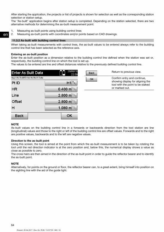
After starting the application, the projects or list of projects is shown for selection as well as the corresponding stationselection or station setup.The “As-built” application begins after station setup is completed. Depending on the station selected, there are twoalternative methods for determining the as-built measurement point:
1. Measuring as-built points using building control lines2. Measuring as-built points with coordinates and/or points based on CAD drawings.
11.3.2 As-built with building control linesWhen taking as-built measurements with control lines, the as-built values to be entered always refer to the buildingcontrol line that has been selected as the reference axis.
Entering an as-built positionEnter the as-built position as a dimension relative to the building control line defined when the station was set or,respectively, the building control line on which the tool is set up.The values to be entered are line and offset distances relative to the previously defined building control line.
Return to previous view.
Confirm entry and continue,showing display for aligning thetool with the point to be stakedor marked out.
NOTEAs-built values on the building control line in a forwards or backwards direction from the tool station are line(longitudinal) values and those to the right or left of the building control line are offset values. Forwards and to the rightare positive values, backwards and to the left are negative values.
Direction to the as-built pointUsing this screen, the tool is aimed at the point from which the as-built measurement is to be taken by rotating thetool until the red direction indicator is at the zero position and, below this, the numerical display shows a value asclose as possible to zero.The cross hairs are then aimed in the direction of the as-built point in order to guide the reflector bearer and to identifythe as-built point.
NOTEAlternatively, for points on the ground or floor, the reflector bearer can, to a great extent, bring himself into position onthe sighting line with the aid of the guide light.
en
64Printed: 20.04.2017 | Doc-Nr: PUB / 5135739 / 000 / 00Printed: 20.04.2017 | Doc-Nr: PUB / 5135739 / 000 / 01

Return to entry of layout values.
Measure distance and continue,showing deviations.
Results of as-built measurementsShows the difference in position in terms of Line, Offset and Height based on the last distance and anglemeasurements.
Return to entry of layout values.
Save the layout values and lastdifferences.Enter the next point.
NOTEIf the option to include heights was not set when the station was set up, height values and all associated informationare not displayed.
Saving as-built data with control linesPt ID Name of layout point.Line (entered) Line distance entered relative to the building control
line.Offset (entered) Offset distance entered relative to the building control
line.Height (entered) Height entered.Line distance (measured) Line distance measured relative to the building control
line.Offset (measured) Offset distance measured relative to the building con-
trol line.Height (measured) Measured height.dO Difference in offset value based on the building control
line. dO = offset (measured) – offset (entered)dL Difference in line value based on the building control
line. dL = line (measured) – line (entered)dH Difference in height. dH = height (measured) – height
(entered)
en
65Printed: 20.04.2017 | Doc-Nr: PUB / 5135739 / 000 / 00Printed: 20.04.2017 | Doc-Nr: PUB / 5135739 / 000 / 01

11.3.3 As-built with coordinatesEntering an as-built pointAn as-built point with point coordinates can be entered in three different ways:
Manual entry of point coordinates.Selection of point coordinates from a list of points saved in memory.Selection of point coordinates from a CAD drawing with points saved in memory.
Return to previous view.
Confirm the entry and continue,showing display for aligning thetool with the point to be meas-ured.
Entering the as-built values (from a CAD drawing)The as-built points, in this case, are selected directly from a CAD drawing.With this method, the point is already incorporated in the drawing as a three-dimensional or two-dimensional pointand can be extracted accordingly.
Shows the point selected fromthe graphical display.Cancel and return to entry of as-built points.Select a point from a plan.
Select a point from a list.
Enter coordinates manually.
Confirm the selected point.
NOTEIf the option to exclude heights is activated when setting up the station, height values and all associated informationare not displayed.
NOTEThe other screens shown are the same as described in the previous section.
Layout results with coordinatesShows the layout difference in terms of coordinates based on the last distance and angle measurements.
en
66Printed: 20.04.2017 | Doc-Nr: PUB / 5135739 / 000 / 00Printed: 20.04.2017 | Doc-Nr: PUB / 5135739 / 000 / 01

Return to entry of layout values.
Save the layout values and lastdifferences.Enter the next point.
Saving data for staking out with coordinatesPt ID Name of layout point.Northings (entered) The northings entered refer to the coordinate reference
system.Height (entered) Height entered.Eastings (entered) The eastings entered refer to the coordinate reference
system.Northings (measured) Measured northings refer to the coordinate reference
system.Height (measured) Measured height.Eastings (measured) Measured eastings refer to the coordinate reference
system.dN Difference in northing based on the coordinate refer-
ence system. dN = delta north (measured) – delta north(entered)
dH Difference in height. dH = height (measured) – height(entered)
dE Difference in coordinate easting based on the coordin-ate reference system. dE = delta east (measured) –delta east (entered)
NOTEThe procedure for as-built with coordinates is the same as for as-built based on a building control line, with theexception that coordinates or coordinate differences are entered or shown as results instead of line or offset distances.
11.4 Missing line11.4.1 The principle of “Missing line”With the “Missing line” application, points anywhere within a certain space can be measured in order to determine thehorizontal distance, slope distance, height difference and slope or angle between the points.
en
67Printed: 20.04.2017 | Doc-Nr: PUB / 5135739 / 000 / 00Printed: 20.04.2017 | Doc-Nr: PUB / 5135739 / 000 / 01
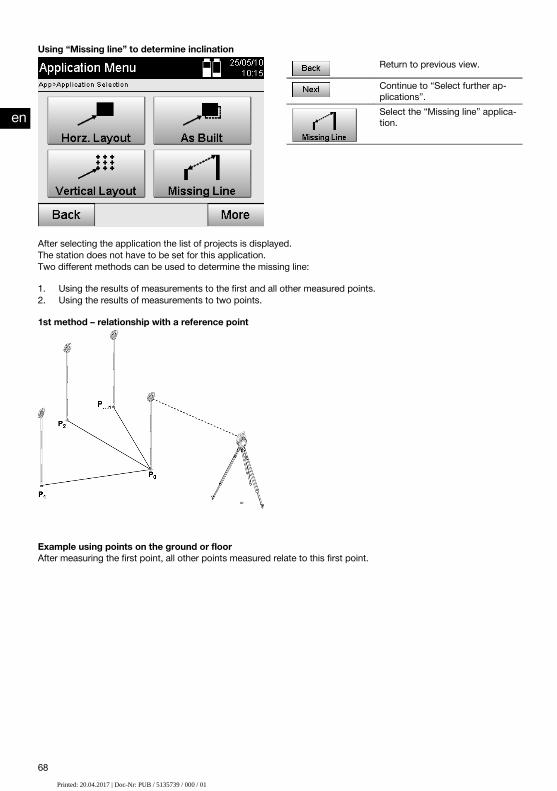
Using “Missing line” to determine inclinationReturn to previous view.
Continue to “Select further ap-plications”.Select the “Missing line” applica-tion.
After selecting the application the list of projects is displayed.The station does not have to be set for this application.Two different methods can be used to determine the missing line:
1. Using the results of measurements to the first and all other measured points.2. Using the results of measurements to two points.
1st method – relationship with a reference point
Example using points on the ground or floorAfter measuring the first point, all other points measured relate to this first point.
en
68Printed: 20.04.2017 | Doc-Nr: PUB / 5135739 / 000 / 00Printed: 20.04.2017 | Doc-Nr: PUB / 5135739 / 000 / 01

2nd method – relationship between the first and second point
Example with points on the ground / floorMeasure the first two points.After obtaining the result, choose a new line and measure the new first point and the new second point.
Measuring to the first reference pointReturn to project selection.
Initiate measurement to point.
Continue to the next measure-ment.
Measuring to the second reference pointReturn to previous view.
Measure angle and distance.
Show the resulting missing line.
en
69Printed: 20.04.2017 | Doc-Nr: PUB / 5135739 / 000 / 00Printed: 20.04.2017 | Doc-Nr: PUB / 5135739 / 000 / 01

The results shownReturn to previous view.
Save results.
Alternative for new line. Continueto entry of a new 1st. referencepoint.Alternative for next point: Calcu-late missing line relative to 1streference point
11.5 Measure and record11.5.1 The principle of “Measure and record”“Measure and record” can be used to measure points with an unknown position.Distances can be measured with the laser when the laser beam can be aimed directly at a surface.Depending on the station setup, the positions of points are calculated with building control line dimensions or withcoordinates and/or heights.The points measured can be assigned various point designations and saved in memory.
NOTEEach time a point is saved, the number assigned to the name of the point is raised by “1”.
The point data saved in memory can be transferred to a PC for further use in a CAD or similar system or printed outfor documentation and archival purposes.The “Measure and record” application can be started by way of the corresponding button in the application menu.
Return to previous view.
Continue to “Select further ap-plications”.Select the “Measure and record”application.
After starting the application, the projects or list of projects is shown for selection as well as the corresponding stationselection or station setup.The “Measure and record” application begins after station setup is completed.Depending on the station setup selected, there are two alternative methods for determining the point system:
1. Point positions that depend on a building control line2. Point positions that depend on a coordinate system
11.5.2 Measure and record with building control linesThe positions of the measured points relate to the building control line used as a reference.The positions are described with a line distance on the building control line and a perpendicular offset distance.
en
70Printed: 20.04.2017 | Doc-Nr: PUB / 5135739 / 000 / 00Printed: 20.04.2017 | Doc-Nr: PUB / 5135739 / 000 / 01

P0 is the position of the tool after setting up.If angles and distances to target points are measured, the corresponding building control line distances L and Q arecalculated and saved in memory.
Measuring points with building control linesMeasuring can begin as soon as station setup has been completed.
Cancel and return to optionsmenu.Save the horizontal distance, ho-rizontal angle and vertical anglevalues shown in the display.Measure and save the horizontaldistance, horizontal angle andvertical angle.Measure distance.
Toggle the display to distancesbetween control lines.Toggle display to angle values.
en
71Printed: 20.04.2017 | Doc-Nr: PUB / 5135739 / 000 / 00Printed: 20.04.2017 | Doc-Nr: PUB / 5135739 / 000 / 01

11.5.3 Measure and record with coordinatesThe positions of the measured points relate to the same coordinate system used for the station setup and aredescribed or, respectively, indicated by coordinate values E or Y, N or X and H for the heights.
P0 is the position of the tool after setting up.Angles and distances to the targets are measured and the corresponding coordinates calculated and saved in memory.
Measuring points with coordinatesThe following screen can be toggled between displaying angles and coordinates.
Cancel and return to the startmenu.Initiate measurement and savedata. The point (designation) isincreased by “1”.Measure distance.
Show coordinates.
Toggle display to angle values.
Save the horizontal distance, ho-rizontal angle and vertical anglevalues shown in the display.
NOTEIf the option to exclude heights is activated when setting up the station, height values and all associated informationare not displayed.
en
72Printed: 20.04.2017 | Doc-Nr: PUB / 5135739 / 000 / 00Printed: 20.04.2017 | Doc-Nr: PUB / 5135739 / 000 / 01

NOTEThe horizontal distance value is fixed by measuring the distance. If the telescope is subsequently moved, only thehorizontal angle and vertical angle values change.
It is sometimes difficult, or even impossible, to make an exact measurement to a certain point (e.g. to the middle of apost or tree). In this case, measure the distance to a different, laterally offset point.
1. Once you have sighted the offset point, measure the distance to it.2. Pivot the telescope and sight the point you actually wish to measure, so that the corresponding angle can be
measured.3. Save the distance measured to the laterally offset point plus the angle to the actual point to be measured.
Saving data in memory with “Measure and record”Pt ID Name of measured pointE(Y), offset Measured easting or offset distance to building control
lineN(X), line Measured northing or line distance along the building
control lineHeight (measured) Measured height
11.6 Vertical alignment11.6.1 The principle of “Vertical alignment”Vertical alignment can be used to check that objects are vertical or to transfer vertical lines.We would like to point out the advantages of this system for setting up formwork for columns in the vertical plane orfor laying out or checking points that lie vertically one above the other over several floors of a building.
NOTEIn principle, two measured points are checked in order to determine whether they lie vertically one above the other.
NOTEDepending on the needs of the application, the measurements can be made with or without use of a reflector rod.
Return to previous view.
Continue to “Select further ap-plications”.Select the “Vertical alignment”application.
en
73Printed: 20.04.2017 | Doc-Nr: PUB / 5135739 / 000 / 00Printed: 20.04.2017 | Doc-Nr: PUB / 5135739 / 000 / 01

After selecting the application the list of projects is displayed.The station does not have to be set for this application.
Measurements to the 1st reference pointThe angle and distance are measured to the 1st reference point.The distance can be measured directly to the point or using the reflector rod, depending on ease of access to the 1streference point.
Return to project selection.
Measure angle and distance tothe 1st. reference point.Continue to the next measure-ment.
Measuring to other pointsThe other points are always determined by taking angle and distance measurements.After the second and each further measurement, the correction values compared to the 1st reference point areupdated in the display below.
Return to “Measuring to the firstreference point”.Save results.
Measure angle and distance andupdate correction values in thedisplay.
11.7 Area measurement11.7.1 The principle of area measurementThe tool can calculate the horizontal or vertical area enclosed by a total of up to 99 consecutively measured points.The points can be measured in a clockwise or counterclockwise sequence.
en
74Printed: 20.04.2017 | Doc-Nr: PUB / 5135739 / 000 / 00Printed: 20.04.2017 | Doc-Nr: PUB / 5135739 / 000 / 01

NOTEThe points must be measured in such a way that the lines between the measured points do not cross each other,otherwise an incorrect area measurement will result.
Return to previous view.
Continue to “Select further ap-plications”.Select the “Area measurement”application.
After starting the application, select whether the area is in the horizontal or vertical plane.
NOTEThe station does not have to be set for this application.
NOTEThe horizontal area is calculated by projecting the measured points in the horizontal plane.
NOTEThe vertical area is calculated by projecting the measured points in the vertical plane. The vertical plane is defined bythe first two measured points.
Measurements for area calculationThe points should be measured in a sequence that encloses an area.For the calculation, enclosure of the area is always completed by an imaginary line between the last measured pointand the first measured point.The points must be measured in such a way that the lines between the measured points do not cross each other,otherwise an incorrect area measurement will result.
en
75Printed: 20.04.2017 | Doc-Nr: PUB / 5135739 / 000 / 00Printed: 20.04.2017 | Doc-Nr: PUB / 5135739 / 000 / 01

Return to project selection.
Delete the last measured point.
Initiate measurement to point.
Show the result of area meas-urement.
ResultsThe results are saved in internal memory and can be displayed on a PC or printed out using Hilti PROFIS Layout.
Return to project selection.
Save the results of area meas-urement.
11.8 Indirect height measurement11.8.1 The principle of indirect height measurementThe indirect height measurement method is used to determine the height difference to inaccessible objects or pointsin situations where direct distance measurement is not possible.Virtually any height or depth, e.g. heights to the extremities of a crane, the depth of an excavation or heights in manyother similar situations can be determined using the indirect height measurement method.
NOTEIt is essential that the reference point and the other inaccessible points all lie in the same vertical plane.
en
76Printed: 20.04.2017 | Doc-Nr: PUB / 5135739 / 000 / 00Printed: 20.04.2017 | Doc-Nr: PUB / 5135739 / 000 / 01

Return to previous view.
Continue to “Select further ap-plications”.Select the “Indirect height meas-urement” application.
After selecting the application the list of projects is displayed.The station does not have to be set for this application.
11.8.2 Indirect height measurementMeasurements to the 1st reference pointThe angle and distance to the 1st reference point are measured.The distance can be measured directly to the point or using the reflector rod, depending on ease of access to the 1streference point.
Return to project selection.
Initiate measurement to point.
Continue to the next measure-ment.
Measuring to other pointsMeasuring to other points is carried out simply by measuring the vertical angles. The difference in height relative tothe 1st reference point is indicated continuously.
New (additional) indirect heightmeasurement based on a newreference point.Save results.
en
77Printed: 20.04.2017 | Doc-Nr: PUB / 5135739 / 000 / 00Printed: 20.04.2017 | Doc-Nr: PUB / 5135739 / 000 / 01

11.9 Determining a point in relation to an axis11.9.1 The principle of “Point in relation to axis”The application “Point in relation to axis”, can be used to determine the position of a point (e.g. a reference point) inrelation to the axis. In addition, points parallel to the axis, at right angles or at any desired angle to it, as well as pointson the existing axis, can also be defined. This application is useful, above all, for example, when nails are to be placedon batter boards to indicate parallel axes on the site.
The application is performed in two steps:
1. Defining the axis.2. Selecting or measuring the reference point.
If the station has been set up in coordinate / graphical mode, the axis and the reference point can be determineddirectly from the data in memory.If the station has not already been set up, the axis must be determined by measuring its starting point and end point.The reference point is also determined by way of direct measurement.
11.9.2 Determining the axisMeasuring or selecting the first point on the axis
Rename point on reference axisor select point form memory.Return to orientation measure-ment.Initiate measurement to point.
Continue to the next step.
Measuring or selecting the second point on the axisRename point on reference axisor select point form memory.Go back to measurement of thefirst point.Initiate measurement to point.
Continue to the next step.
Shifting the axisThe axis starting point can be shifted in order to use a different reference point as the origin of the coordinate system.If the value entered is positive, the axis is moved forward. If it is negative, the axis is moved back. A positive valueshifts the starting point to the right and a negative value shifts it to the left.
en
78Printed: 20.04.2017 | Doc-Nr: PUB / 5135739 / 000 / 00Printed: 20.04.2017 | Doc-Nr: PUB / 5135739 / 000 / 01

Return to previous view.
Enter axis shift manually.
Take measurement to point. Theaxis, distance and height valuesare shown. The values can beindividually labeled.Rotate axis.
Continue to the next step.
Rotating the axisThe axis bearing (direction) can be rotated about the starting point. If the value entered is positive, the axis is rotatedclockwise. If it is negative, the axis is rotated counterclockwise.
Return to previous view.
Confirm rotation.
11.9.3 Checking points in relation to the axisMeasuring or selecting reference points
Select point from memory.
Initiate measurement to point.
Show the measured or selectedpoints in relation to the referenceaxis.Save measurements.
Determine new reference axis.
en
79Printed: 20.04.2017 | Doc-Nr: PUB / 5135739 / 000 / 00Printed: 20.04.2017 | Doc-Nr: PUB / 5135739 / 000 / 01

12 Data and data handling12.1 IntroductionHilti total stations always save data in internal memory.The data consists of measured values, i.e. angles and distances or, depending on settings or the application, valuesrelative to the building control line such as line and offset values or coordinates.With the aid of PC software, data can be exchanged with other systems.In principle, all total station data should be regarded as point data, with the exception of graphical data in which thepoints are incorporated.The applicable points are available for selection and use, but not the graphics data itself, which simply providesadditional information.
12.2 Point dataPoint data can consist of new measured points or existing points. The total station basically measures angles anddistances.The station setup allows target point coordinates to be calculated.Accordingly, each point that has been sighted with the cross hairs or laser pointer and the distance to it measured iscalculated by the total station as a three-dimensional point.These three-dimensional points are clearly identified by point designations.A point designation, a Y-coordinate, an X-coordinate and possibly a height are given for each point.Given points are defined by their coordinates or points with graphical elements.
12.2.1 Points in the form of measured pointsMeasurement data takes the form of measured points generated and saved in memory as coordinate points on thetotal station by the relevant application, e.g. Horz. Layout, Vert. Layout, As-built and Measure and Record.Measured points exist only as a single instance within a station.If the same name is used again for a measured point, the existing measured point can be overwritten or another pointname assigned to it.Measured points cannot be edited.
12.2.2 Points in the form of coordinate pointsWhen working with the coordinate system, all positions are, as a rule, defined by a point name and coordinates - atleast a point name and two horizontal coordinates X, Y or E, N are necessary to describe a point position.The height is generally independent of the XY coordinate values.The total station uses points in the form of coordinate points - so-called control points or fixed points and measuredpoints with coordinates.Fixed points are points with given coordinates, which are entered manually on the total station or transferred fromUSB memory or directly by way of a USB cable with the aid of Hilti PROFIS Layout.These fixed points may also be layout points. A control point (fixed point) in a project is unique (the only one).Control points or fixed points can be edited on the total station so long as no graphical element is attached tothe point.
12.2.3 Points with graphical elementsWith the aid of Hilti PROFIS Layout, graphical data can be transferred from a CAD environment, shown on the screenand selected for use.The Hilti system allows points and graphical elements to be created in various ways using Hilti PROFIS Layout, and tosubsequently transfer these to the total station for further use.Points with attached graphical elements cannot be edited on the total station but can be edited on a PC usingHilti PROFIS Layout.
12.3 Generation of point data12.3.1 With the total stationEach measurement taken generates a measurement data set or, respectively, a measured point. Measured points aredefined either only as angle and distance values, point name with angle and distance values or as point name withcoordinates.
en
80Printed: 20.04.2017 | Doc-Nr: PUB / 5135739 / 000 / 00Printed: 20.04.2017 | Doc-Nr: PUB / 5135739 / 000 / 01

12.3.2 With Hilti PROFIS Layout1. Generating points from a model consisting of lines and curves shown with graphical elementsWith the PC application Hilti PROFIS Layout, dimensions from the building plan can be used to generate a graphicallayout which is a reproduction, so to speak, of the building plan.With the aid of this application, the plan is reproduced in simplified graphical form on the PC, resulting in lines andcurves, etc. on a graphical background.In doing so, specific curves can be created, from which points can be generated, e.g. at regular intervals.
2. Generating points from imported CAD and CAD-compatible dataWith the aid of Hilti PROFIS Layout CAD data in the DXF or AutoCAD-compatible DWG format can be transferred toa PC.Points are then generated from the graphical data, i.e. lines, curves etc.Hilti PROFIS Layout offers the possibility of using CAD graphics to generate point data from end points, lineintersections, mid points of line segments and points on circles, etc.The point data generated in this way is placed visibly on the original graphics elements from CAD.The data in a CAD format can exist in various “layers”. When this data is transferred to Hilti PROFIS Layout it is mergedinto a single layer.
NOTEWhen organizing the data on the PC before it is transferred to the tool, special care must be taken to ensure that the“density” of the point data is as to be expected in the final result.
3. Importing data from tables or text filesPoint data can be imported into Hilti PROFIS Layout from text or XML files and then transferred to the total station.
12.4 Data memory12.4.1 Total station internal memoryThe Hilti total station saves and organizes application data correspondingly in memory.Point or measurement data is organized in the system according to projects and stations.
ProjectA single block of control points (fixed points) or layout points belongs to a project.A number of stations may belong to a project.
Tool station plus orientation (where relevant)A station must always have an orientation.Measured points with unique point designations belong to a station.
NOTEA project can be regarded as a file, so to speak.
12.4.2 USB memoryUSB memory allows data to be transferred between a PC and the total station. It is not used as additional mainmemory.
NOTEThe total station’s internal memory is always used as its active main memory.
13 Total station data manager13.1 OverviewThe Data Manager provides access to the data stored in the total station’s internal memory.The Data Manager offers the following possibilities:
en
81Printed: 20.04.2017 | Doc-Nr: PUB / 5135739 / 000 / 00Printed: 20.04.2017 | Doc-Nr: PUB / 5135739 / 000 / 01

Creating, deleting and copying new projects.Entering, editing and deleting the coordinates of control points (fixed points).Displaying and deleting measured points.
Return to previous view.
Select the “Data manager” ap-plication.
NOTEControl points (fixed points) can be edited only when these are not attached to graphical data.
13.2 Selecting a jobAfter starting the Data Manager, the list of existing jobs in internal memory is shown.An existing job must be selected before the functions for points and measured points become active.
Return to previous view.
View job details.
Copy the selected job.
Delete the selected job.
Select or create a new project.
Return to previous view.
Select functions for fixed points.
Select functions for the meas-ured point.
en
82Printed: 20.04.2017 | Doc-Nr: PUB / 5135739 / 000 / 00Printed: 20.04.2017 | Doc-Nr: PUB / 5135739 / 000 / 01

13.2.1 Fixed points (control points or layout points)After selecting the applicable job, the option “Points” can be selected in order to enter points with coordinates or toedit or delete existing points with coordinates.
13.2.1.1 Entering points with coordinatesManual entry of the point name and coordinates.If the point name already exists the corresponding warning is displayed, requesting the user to change the point name.
Return to previous view.
Select a point from a plan.
Select a point from a list.
Enter a point manually.
Confirm and apply the entry.
NOTEThe button for the function currently in use is shown in gray.
13.2.1.2 Selecting points from a list or graphical representationA selection of points from a list and graphical representation is shown below.
Cancel and return to previousscreen.Select a point from a plan.
Select a point from a list.
Select a point by manual entry.
Confirm and apply the entry.
en
83Printed: 20.04.2017 | Doc-Nr: PUB / 5135739 / 000 / 00Printed: 20.04.2017 | Doc-Nr: PUB / 5135739 / 000 / 01

13.2.1.3 Editing and deleting pointsAfter selecting and confirming the point, it can then be edited or deleted on the following screen.When editing a point, only its coordinates and height can be changed, not the name of the point.In order to change its name, the point has to be reentered in the system under a different name.
Return to previous view.
Delete the point shown.
Edit the point shown.
NOTEPoints with attached graphics can neither be changed nor deleted. This is possible only when working on a PC withHilti PROFIS Layout.
13.2.2 Measured pointsAfter selecting the applicable project, the stations and their associated measured points can be displayed.A station and all the measured points associated with it can also be deleted.In order to do this, the option “Measured points” should be selected when selecting the project.
13.2.2.1 Selecting the stationStation selection by way of manual entry of the station name, selection from a list or from a graphical display areillustrated below.
en
84Printed: 20.04.2017 | Doc-Nr: PUB / 5135739 / 000 / 00Printed: 20.04.2017 | Doc-Nr: PUB / 5135739 / 000 / 01

Cancel and return to previousscreen.Select a point from a plan.
Delete the station and all associ-ated measured points.Select a point from a list.
Confirm and apply the entry.
13.2.2.2 Selecting measured pointsAfter selecting the station, a measured point can be searched for by making a manual entry, selected from a list ofmeasured points or selected from the graphical display.
en
85Printed: 20.04.2017 | Doc-Nr: PUB / 5135739 / 000 / 00Printed: 20.04.2017 | Doc-Nr: PUB / 5135739 / 000 / 01

Cancel and return to previousscreen.Select a point from a plan.
Delete point.
Select a point from a list.
Confirm and apply the entry.
13.2.2.3 Deleting and displaying measured pointsAfter selecting the measured point, the measured values and coordinates can be displayed and the measured pointthen deleted.
Return to previous view.
Delete point.
Show measurement data.
Show coordinates.
Show distances between controllines.
13.3 Deleting a projectBefore a project is deleted, the user is required to confirm this action and is given the opportunity to again view detailsof the project before deletion.
NOTEWhen a project is deleted, all data associated with the project is lost.
en
86Printed: 20.04.2017 | Doc-Nr: PUB / 5135739 / 000 / 00Printed: 20.04.2017 | Doc-Nr: PUB / 5135739 / 000 / 01

13.4 Creating a new projectWhen entering the name of a new project, care must be taken to ensure that the name of the project does not alreadyexist in memory.
Enter project name.Cancel and return to project se-lection.Confirm and apply the entry.
13.5 Copying a projectThere are various possibilities when copying a project:
Copying from internal memory to internal memory.Copying from internal memory to USB memory.Copying from USB memory to internal memory.
When copying, the name of the project in target memory can be changed.It is thus possible to duplicate project data by copying and renaming the project.
Select main memory.Select target memory.Cancel and return to previousscreen.Confirm and apply the entry.
NOTEIf the name of the project already exists in target memory, a different name must be selected or the existing projectfirst deleted.
en
87Printed: 20.04.2017 | Doc-Nr: PUB / 5135739 / 000 / 00Printed: 20.04.2017 | Doc-Nr: PUB / 5135739 / 000 / 01
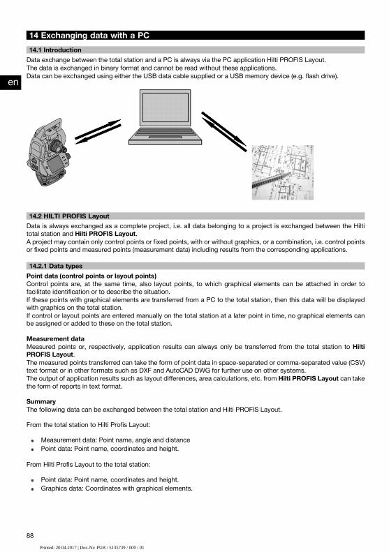
14 Exchanging data with a PC14.1 IntroductionData exchange between the total station and a PC is always via the PC application Hilti PROFIS Layout.The data is exchanged in binary format and cannot be read without these applications.Data can be exchanged using either the USB data cable supplied or a USB memory device (e.g. flash drive).
14.2 HILTI PROFIS LayoutData is always exchanged as a complete project, i.e. all data belonging to a project is exchanged between the Hiltitotal station and Hilti PROFIS Layout.A project may contain only control points or fixed points, with or without graphics, or a combination, i.e. control pointsor fixed points and measured points (measurement data) including results from the corresponding applications.
14.2.1 Data typesPoint data (control points or layout points)Control points are, at the same time, also layout points, to which graphical elements can be attached in order tofacilitate identification or to describe the situation.If these points with graphical elements are transferred from a PC to the total station, then this data will be displayedwith graphics on the total station.If control or layout points are entered manually on the total station at a later point in time, no graphical elements canbe assigned or added to these on the total station.
Measurement dataMeasured points or, respectively, application results can always only be transferred from the total station to HiltiPROFIS Layout.The measured points transferred can take the form of point data in space-separated or comma-separated value (CSV)text format or in other formats such as DXF and AutoCAD DWG for further use on other systems.The output of application results such as layout differences, area calculations, etc. from Hilti PROFIS Layout can takethe form of reports in text format.
SummaryThe following data can be exchanged between the total station and Hilti PROFIS Layout.
From the total station to Hilti Profis Layout:
Measurement data: Point name, angle and distancePoint data: Point name, coordinates and height.
From Hilti Profis Layout to the total station:
Point data: Point name, coordinates and height.Graphics data: Coordinates with graphical elements.
en
88Printed: 20.04.2017 | Doc-Nr: PUB / 5135739 / 000 / 00Printed: 20.04.2017 | Doc-Nr: PUB / 5135739 / 000 / 01
NOTENo provision has been made for direct data exchange between the total station and other PC systems, this can bedone only by using Hilti PROFIS Layout.
14.2.2 Hilti PROFIS Layout data output (export)Data is saved in the following applications and can be exported with the aid of Hilti PROFIS Layout in various formats:
1. Horizontal layout2. Vertical layout3. As-built4. Measure and record5. Area measurement (calculation)
Data outputHilti PROFIS Layout reads the data saved by the total station and extracts the following data.
1. Point name, horizontal angle, vertical angle, distance, reflector height, tool height2. Point name, E(Y) coordinate, N(X) coordinate, height3. Application results such as differences in layouts and area measurements
Output formatsCSV format Comma-separated values.Text format Gaps between data filled with spaces so that individual
data items appear in columns.DXF format Text exchange format compatible with CAD.DWG format Binary data format compatible with AutoCad.
14.2.3 Hilti PROFIS Layout data input (import)Data inputUsing Hilti PROFIS Layout, the following data can be read, converted and transferred to the total station directly bycable or on a USB memory device:
1. Point names (fixed points) with coordinates and heights.2. Polylines (lines, curves) from other systems
Input formatsCSV format Comma-separated values.txt format Space-separated values.Text format Gaps between data filled with spaces so that individual
data items appear in columns.DXF format CAD drawing with lines and curves as general CAD
data exchange format.DWG format CAD drawing with lines and curves as data exchange
format compatible with AutoCad.
15 Calibration and adjustment15.1 In-the-field calibrationThe tool is correctly adjusted when supplied.The values to which the tool is set may change over time or due to temperature fluctuations, transport or aging.The tool therefore incorporates a feature that allows the settings to be checked and, if necessary, corrected by carryingout in-the-field re-calibration.This is done by setting up the tool securely on a tripod of good quality and targeting an easily visible, clearly discernibleobject within ±3 degrees of horizontal at a distance of approx. 70 – 120 m. After this, a measurement is taken intelescope position 1 and in telescope position 2.
en
89Printed: 20.04.2017 | Doc-Nr: PUB / 5135739 / 000 / 00Printed: 20.04.2017 | Doc-Nr: PUB / 5135739 / 000 / 01

NOTEInteractive instructions for this procedure are shown in the display, so it is simply a matter of following the instructions.
This application calibrates and adjusts the following three axes of the tool:
Target axisVA collimationDual-axis compensator (both axes)
15.2 In-the-field calibrationNOTEThe tool should be operated carefully in order to avoid vibration.
NOTEThe in-the-field calibration procedure requires great care and each step must be carried out very exactly. Imprecisesighting or vibration of the tool can result in incorrect calibration values, leading to subsequent measurement errors.
NOTEIn the event of uncertainty the tool should be returned to Hilti Service for checking.
1. Set up the tool in a steady, secure position on a good tripod.2. Select “Configuration” from the application menu.
Cancel and return to optionsmenu.Select the calibration menu andshow the values saved in thetool.
3. Then select “Calibration”.Begin calibration process.
Confirm the calibration valueshown and return to the config-uration menu.
4. Start the calibration procedure or, alternatively, confirm the calibration value shown and thus cancel recalibration.
en
90Printed: 20.04.2017 | Doc-Nr: PUB / 5135739 / 000 / 00Printed: 20.04.2017 | Doc-Nr: PUB / 5135739 / 000 / 01

5. Select a clearly visible target within ± 3 degrees from horizontal at a distance of approx. 70-120 m and sight thistarget carefully.NOTE Find a suitable target that can be sighted easily and accurately.NOTE If the tool is not in the 1st telescope position a message in the display will instruct you to bring it into thisposition.
Return to previous view.
Take measurement at telescopeposition 1.
6. Take the measurement in telescope position 1.You will then be instructed to change to telescope position 2.
7. Pivot the tool carefully into the 2nd telescope position.
en
91Printed: 20.04.2017 | Doc-Nr: PUB / 5135739 / 000 / 00Printed: 20.04.2017 | Doc-Nr: PUB / 5135739 / 000 / 01

Return to previous view.
Take measurement at telescopeposition 2.
8. Re-sight the same target within ± 3° of horizontal.NOTE This step is assisted by the display which shows the differences for the vertical circle and the horizontalcircle. This serves exclusively as a sighting aid.NOTE The values should be very close to zero, i.e. with a deviation of only a few seconds, when the target issighted with the telescope in the second position.
9. Take the measurement in telescope position 2.When measurements have been taken successfully in both telescope positions the new and the old settings forthe vertical index and the target axis are shown.
Cancel and retain old values.
Apply and save new calibrationvalues.
10. Adopt and save the new calibration values.NOTE New settings for the dual-axis compensator are also determined by way of the calibration procedure forthe vertical index and target axis previously described.When the new calibration values are adopted, the new settings for the compensator are also adopted.
15.3 Hilti Calibration ServiceWe recommend that the tool is checked by the Hilti Calibration Service at regular intervals in order to verify its reliabilityin accordance with standards and legal requirements.Use can be made of the Hilti Calibration Service at any time, but checking at least once a year is recommended.The Calibration Service provides confirmation that the tool is in conformance, on the day it is tested, with thespecifications given in the operating instructions.The tool will be readjusted if deviations from the manufacturer’s specification are found.After checking and adjustment, a calibration sticker applied to the tool and a calibration certificate provide writtenverification that the tool operates in accordance with the manufacturer’s specification.Calibration certificates are always required by companies certified according to ISO 900x. Your local Hilti Center orrepresentative will be pleased to provide further information.
en
92Printed: 20.04.2017 | Doc-Nr: PUB / 5135739 / 000 / 00Printed: 20.04.2017 | Doc-Nr: PUB / 5135739 / 000 / 01

16 Care and maintenanceNOTEHave damaged parts replaced by Hilti Service.
16.1 Cleaning and dryingBlow any dust off the glass.CAUTIONDo not touch the glass surfaces with your fingers.
Use only a soft, clean cloth to clean the tool. If necessary,the cloth may be moistened with a little pure alcohol orwater.CAUTIONDo not use liquids other than alcohol or water. Otherliquids may damage plastic parts.
NOTEHave damaged parts replaced by Hilti Service.
16.2 StorageNOTEDo not put the tool into storage when wet. Allow it to drybefore putting it away.
NOTEAlways clean the tool, its transport container and ac-cessories before putting them into storage.
NOTECheck the accuracy of the equipment before it is usedafter a long period of storage or transportation.
CAUTIONRemove the batteries if the tool is to remain unused fora long period of time. Leaking batteries may damage thetool.
NOTEObserve the specified temperature limits when storingyour equipment, above all in winter and summer, es-pecially if the equipment is stored in a motor vehicle(-30°C to +70°C (-22°F to +158°F)).
16.3 TransportCAUTIONThe batteries must be insulated or removed from thetool before the tool is shipped or sent by mail. Leakingbatteries may damage the tool.
Use the Hilti shipping box or packaging of equivalentquality for transporting or shipping your equipment.
17 DisposalWARNINGImproper disposal of the equipment may have serious consequences:The burning of plastic components generates toxic fumes which may present a health hazard.Batteries may explode if damaged or exposed to very high temperatures, causing poisoning, burns, acid burns orenvironmental pollution.Careless disposal may permit unauthorized and improper use of the equipment. This may result in serious personalinjury, injury to third parties and pollution of the environment.
Most of the materials from which Hilti tools or appliances are manufactured can be recycled. The materials must becorrectly separated before they can be recycled. In many countries, Hilti has already made arrangements for takingback old tools or appliances for recycling. Ask Hilti Customer Service or your Hilti representative for further information.
For EC countries onlyDo not dispose of electronic measuring tools or appliances together with household waste.In observance of the European Directive on waste electrical and electronic equipment and its imple-mentation in accordance with national law, electric tools and batteries that have reached the end of theirlife must be collected separately and returned to an environmentally compatible recycling facility.
Dispose of the batteries in accordance with national regulations. Please help us to protect the environ-ment.
en
93Printed: 20.04.2017 | Doc-Nr: PUB / 5135739 / 000 / 00Printed: 20.04.2017 | Doc-Nr: PUB / 5135739 / 000 / 01

18 Manufacturer’s warrantyHilti warrants that the tool supplied is free of defects inmaterial and workmanship. This warranty is valid so longas the tool is operated and handled correctly, cleanedand serviced properly and in accordance with the HiltiOperating Instructions, and the technical system is main-tained. This means that only original Hilti consumables,components and spare parts may be used in the tool.
This warranty provides the free-of-charge repair or re-placement of defective parts only over the entire lifespanof the tool. Parts requiring repair or replacement as aresult of normal wear and tear are not covered by thiswarranty.
Additional claims are excluded, unless stringent na-tional rules prohibit such exclusion. In particular, Hiltiis not obligated for direct, indirect, incidental or con-sequential damages, losses or expenses in connec-tion with, or by reason of, the use of, or inability touse the tool for any purpose. Implied warranties ofmerchantability or fitness for a particular purpose arespecifically excluded.
For repair or replacement, send the tool or related partsimmediately upon discovery of the defect to the addressof the local Hilti marketing organization provided.
This constitutes Hilti’s entire obligation with regard towarranty and supersedes all prior or contemporaneouscomments and oral or written agreements concerningwarranties.
19 FCC statement (applicable in US) / IC statement (applicable in Canada)CAUTIONThis equipment has been tested and found to complywith the limits for a class B digital device, pursuant topart 15 of the FCC rules. These limits are designed toprovide reasonable protection against harmful interfer-ence in a residential installation. This equipment gen-erates, uses and may radiate radio frequency energy.Accordingly, if not installed and used in accordance withthe instructions, it may cause harmful interference toradio communications.
However, there is no guarantee that interference will notoccur in a particular installation. If this equipment doescause harmful interference to radio or television recep-
tion, which can be determined by turning the equipmenton and off, the user is encouraged to try to correct theinterference by one or more of the following measures:
Re-orient or relocate the receiving antenna.
Increase the distance between the equipment and re-ceiver.
Consult the dealer or an experienced TV/radio technicianfor assistance.
NOTEChanges or modifications not expressly approved by Hilticould void the user’s authority to operate the equipment.
en
94Printed: 20.04.2017 | Doc-Nr: PUB / 5135739 / 000 / 00Printed: 20.04.2017 | Doc-Nr: PUB / 5135739 / 000 / 01

20 EC declaration of conformity (original)Designation: Total stationType: POS 15/18Generation: 01Year of design: 2010
We declare, on our sole responsibility, that this productcomplies with the following directives and standards:2011/65/EU, 2006/95/EC, 2004/108/EC.
Hilti Corporation, Feldkircherstrasse 100,FL‑9494 Schaan
Paolo Luccini Matthias GillnerHead of BA Quality and Process Man-agement
Executive Vice President
Business Area Electric Tools & Ac-cessories
Business Area ElectricTools & Accessories
01/2012 01/2012
Technical documentation filed at:Hilti Entwicklungsgesellschaft mbHZulassung ElektrowerkzeugeHiltistrasse 686916 KauferingDeutschland
IndexAAC adapter . . . . . . . . . . . . . . . . . . . . . . . 6POA 81 . . . . . . . . . . . . . . . . . . . . . . . . 6
Adjusting key set . . . . . . . . . . . . . . . . . . 6-7Area measurement . . . . . . . . . . . . . . . . . 3, 74As-built . . . . . . . . . . . . . . . . . . . . . . . 3, 63with building control lines . . . . . . . . . . . . 3, 64with coordinates . . . . . . . . . . . . . . . . . 3, 66
Atmospheric influence . . . . . . . . . . . . . . . 3, 32
BBattery . . . . . . . . . . . . . . . . . . . 2, 6, 20, 22inserting and changing . . . . . . . . . . . . . . 2, 20POA 80 . . . . . . . . . . . . . . . . . . . . . . . . 6
CCarrying handle . . . . . . . . . . . . . . . . . . . . . 1ChargerPOA 82 . . . . . . . . . . . . . . . . . . . . . . . . 6
Checking functions . . . . . . . . . . . . . . . . . 2, 20Checking pointsin relation to the axis . . . . . . . . . . . . . . . 3, 79
Configuration . . . . . . . . . . . . . . . . . . . . 2, 27Control lines . . . . . . . . . . . . . . . . . . . . . 1, 11Control panel . . . . . . . . . . . . . . . . . . . . 2, 20
Control points . . . . . . . . . . . . . . . . . . . . 4, 83Coordinates . . . . . . . . . . . . . . . . . . . . . 1, 11Correctionatmospheric influences . . . . . . . . . . . . . . 3, 32
Correction of atmospheric influences . . . . . . . 3, 31
DData points . . . . . . . . . . . . . . . . . . . . . 2, 18Data types . . . . . . . . . . . . . . . . . . . . . . 4, 88Determining the axis . . . . . . . . . . . . . . . . 3, 78Display illumination . . . . . . . . . . . . . . . . . 2, 31Distance measurement . . . . . . . . . . . . . . . 2, 15Dual-axis compensator . . . . . . . . . . . . . . . 2, 15
EElectronic bubble level . . . . . . . . . . . . . . . 3, 31Entering pointsDeleting points . . . . . . . . . . . . . . . . . . . 84Editing points . . . . . . . . . . . . . . . . . . . . 84Selecting points . . . . . . . . . . . . . . 2, 18, 83with coordinates . . . . . . . . . . . . . . . . . . 83
Entering the station position . . . . . . . . . . . . . 36Entering the target point . . . . . . . . . . . . . 37, 42Eyepiece . . . . . . . . . . . . . . . . . . . . . . . . 1
en
95Printed: 20.04.2017 | Doc-Nr: PUB / 5135739 / 000 / 00Printed: 20.04.2017 | Doc-Nr: PUB / 5135739 / 000 / 01

FFixed point . . . . . . . . . . . . . . . . . . . . . 4, 83Focussing knob . . . . . . . . . . . . . . . . . . . . . 1Function buttons . . . . . . . . . . . . . . . . . . 2, 20Function menuFNC . . . . . . . . . . . . . . . . . . . . . . . . 2, 30
GGuide light . . . . . . . . . . . . . . . . . . 1-2, 18, 30
HHeight measurement . . . . . . . . . . . . . . . . 2, 17Hilti Calibration Service . . . . . . . . . . . . . . . 4, 92HILTI PROFIS Layout . . . . . . . . . . . . . . . 4, 88Data input (import) . . . . . . . . . . . . . . . . 4, 89Data output (export) . . . . . . . . . . . . . . . 4, 89
Horizontal circle display . . . . . . . . . . . . . . 2, 25Horizontal layout(Horz. Layout) . . . . . . . . . . . . . . . . . . . 3, 50
IInclination indicatorVertical . . . . . . . . . . . . . . . . . . . . . . 2, 26
Indirect height measurement . . . . . . . . . . 3, 76-77In-the-field calibration . . . . . . . . . . . . . 4, 89-90
JJobselecting . . . . . . . . . . . . . . . . . . . . . 4, 82
LLaser plummet . . . . . . . . . . . . . . . . . . . . . 1Laser pointer . . . . . . . . . . . . . . . . . 2, 18, 31Status indicator . . . . . . . . . . . . . . . . . . 2, 22
Laying outwith building control lines . . . . . . . . . . . . 3, 51with coordinates . . . . . . . . . . . . . . . . . 3, 54
Layout points . . . . . . . . . . . . . . . . . . . . 4, 83
MMeasure and record . . . . . . . . . . . . . . . . 3, 70with building control lines . . . . . . . . . . . . 3, 70with coordinates . . . . . . . . . . . . . . . . . 3, 72
Measured point . . . . . . . . . . . . . . . . . . 4, 84deleting and displaying . . . . . . . . . . . . . . . 86
Measuring principle . . . . . . . . . . . . . . . . . 2, 15Missing line . . . . . . . . . . . . . . . . . . . . . 3, 67
OObjective lens . . . . . . . . . . . . . . . . . . . . . . 1
PPOA 50Reflector rod (metric) . . . . . . . . . . . . . . . . . 6
POA 51Reflector rod (imperial) . . . . . . . . . . . . . . . . 7
POA 80Battery . . . . . . . . . . . . . . . . . . . . . . . . 6
POA 82Charger . . . . . . . . . . . . . . . . . . . . . . . . 6
POAW‑4Reflector foil . . . . . . . . . . . . . . . . . . . . . 7
Point in relation to axis . . . . . . . . . . . . . . . 3, 78Position of the station . . . . . . . . . . . . . . . . . 41Projectcopying . . . . . . . . . . . . . . . . . . . . . . 4, 87create new . . . . . . . . . . . . . . . . . . . . 3, 33creating new . . . . . . . . . . . . . . . . . . . 4, 87deleting . . . . . . . . . . . . . . . . . . . . . . 4, 86
Project information . . . . . . . . . . . . . . . . . 3, 34Projects . . . . . . . . . . . . . . . . . . . . . . . 3, 32PUA 35 tripod . . . . . . . . . . . . . . . . . . . . . . 7
RReading the circle . . . . . . . . . . . . . . . . 2, 25-26Reflector foilPOAW‑4 . . . . . . . . . . . . . . . . . . . . . . . 7
Reflector rod . . . . . . . . . . . . . . . . . . . . . . 6POA 50 . . . . . . . . . . . . . . . . . . . . 2, 6, 16POA 51 . . . . . . . . . . . . . . . . . . . . . . . . 7
SSelecting a project . . . . . . . . . . . . . . . . . 3, 33Selecting measured points . . . . . . . . . . . . . . 85Selecting the station . . . . . . . . . . . . . . . . . 84Setting a station “anywhere” . . . . . . . . . 3, 43, 45Setting up the tool . . . . . . . . . . . . . . . . . 2, 23over a pipe using the laser plummet . . . . . . . 2, 24
Showing the active project . . . . . . . . . . . . . 3, 32Switching the appliance on . . . . . . . . . . . . . 2, 23Switching the tool off . . . . . . . . . . . . . . . . 2, 23
TTargets . . . . . . . . . . . . . . . . . . . . . . . 2, 16Telescope positions . . . . . . . . . . . . . . . . . 2, 13The toolSetting up . . . . . . . . . . . . . . . . . . . . . 2, 23
Theodolite . . . . . . . . . . . . . . . . . . . . . . 2, 24Time and date . . . . . . . . . . . . . . . . . . . . 2, 29
en
96Printed: 20.04.2017 | Doc-Nr: PUB / 5135739 / 000 / 00Printed: 20.04.2017 | Doc-Nr: PUB / 5135739 / 000 / 01

Total station . . . . . . . . . . . . . . . . . . . . . . 6Switching off . . . . . . . . . . . . . . . . . . . 2, 23
Touch screenAlphanumerical keyboard . . . . . . . . . . . . 2, 22Division . . . . . . . . . . . . . . . . . . . . . . 2, 21General operating controls . . . . . . . . . . . . 2, 22Numerical keyboard . . . . . . . . . . . . . . . 2, 21Size . . . . . . . . . . . . . . . . . . . . . . . . 2, 21
Tribrach . . . . . . . . . . . . . . . . . . . . . . . . . 1
VVertical alignment . . . . . . . . . . . . . . . . . . 3, 73Vertical drive . . . . . . . . . . . . . . . . . . . . . . 1Vertical layoutVertical layout . . . . . . . . . . . . . . . . . . . 3, 57with building control lines . . . . . . . . . . . . 3, 58with coordinates . . . . . . . . . . . . . . . . . 3, 61
en
97Printed: 20.04.2017 | Doc-Nr: PUB / 5135739 / 000 / 00Printed: 20.04.2017 | Doc-Nr: PUB / 5135739 / 000 / 01

*433674*
4336
74
Hilti CorporationLI-9494 SchaanTel.: +423 / 234 21 11Fax:+423 / 234 29 65www.hilti.com
Hilti = registered trademark of Hilti Corp., Schaan W 3881 | 0113 | 00-Pos. 6 | 1 Printed in Germany © 2013Right of technical and programme changes reserved S. E. & O. 433674 / A3
Printed: 20.04.2017 | Doc-Nr: PUB / 5135739 / 000 / 00Printed: 20.04.2017 | Doc-Nr: PUB / 5135739 / 000 / 01