Embed Size (px)
Citation preview

Date of issue 04/04
Siemens Electronic Designand Manufacturing Services
Operating InstructionsComfort Lift Door DriveAT 25A


Date of issue 04/04 Table of Contents
Operating Instructions AT 25A
SEDM1
1 Table of Contents
1 Table of Contents...................................................................................12 Introduction ...........................................................................................23 Notes on Safety.....................................................................................34 Overview of Controls and Indicators .....................................................45 Functions and Device Reactions ...........................................................5
5.1 Learning and Test Run...................................................................55.2 DOOR-OPEN Command ...............................................................55.3 DOOR-CLOSE Command..............................................................55.4 Service Buttons.............................................................................55.5 Detection of Blocking....................................................................65.6 Restart after Voltage Loss.............................................................65.7 Closing Force.................................................................................65.8 Emergency Release ......................................................................65.9 Nudging.........................................................................................75.10 Light Barrier...................................................................................75.11 Emergency Electric Power Supply ................................................75.12 Overload Protection.......................................................................75.13 User Terminal ................................................................................8
6 Mechanical Assembly and Setting ........................................................97 Electric Setting and Commissioning....................................................108 Relay Contacts.....................................................................................139 Travelling Curve ...................................................................................1410 Display of Operating State...................................................................1511 Speed Limit .........................................................................................1612 Technical Data......................................................................................17
12.1 D.C. Gear Motor (Overall Door Mass 120 and 400 kg)................1712.2 Mains Transformer (Overall Door Mass 120 and 400 kg)............1712.3 Control Device AT 25A (Overall Door Mass 120 and 400 kg).......1812.4 Tests............................................................................................18
13 Appendix..............................................................................................1913.1 Appendix 1: Ident. Numbers of the Individual Parts ...................1913.2 Appendix 2: Dimension Sheet Control Device AT 25A ................2013.3 Appendix 3: Dimension Sheet Mains Transformer AT 25A..........2113.4 Appendix 4: 40 V Gear Motor, Driving Pinion Left, with Rubber-
Metal Connection and Assembly Bracket...............2213.5 Appendix 5: 30 V Gear Motor, Driving Pinion Right, with Rubber-
Metal Connection and Assembly Bracket...............2313.6 Appendix 6: Deflection Roller with Tightening Device
and Assembly Bracket ............................................2413.7 Appendix 7: Door Carrier.............................................................2513.8 Appendix 8: Assembly Recommendation...................................2613.9 Appendix 9: Wiring Diagram Control Inputs................................2713.10 Setting Log: ...............................................................................28

Introduction
2
2 Introduction
The comfort lift door drive AT 25A is an “intelligent” door drive which is usedto actuate lift car doors and landing entrances at adjustable speeds andaccelerations.
The maintenance-free drive unit consists of a d.c. motor with a nonselflockinggear and is operated with speed control. The transmission is performed usinga toothed belt. The toothed belt is guided across a deflection roller and canbe equipped with two door carriers. Thus, doors opening on one side as wellas centrally opening doors can be driven.
Two variants of motor are available:
- 40 V motor, 1.65 A for maximum 120 kg overall door mass
- 30 V motor, 4.0 A for maximum 400 kg overall door mass
Both door drives can be ordered with a differently mounted driving pinion(left or right, refer to drawing in Appendix).
The controller identifies the type of the connected motor automatically.
No limit switches are required for the operation of the door drive. The doorwidth as well as the positions ”OPEN“ and ”CLOSE“ are automaticallydetermined.
The current operating states are shown on a 7-segment display (IC-206) inthe control device.
For all important dimensioned drawings, an assembly recommendation andthe ident. numbers to order the individual drive components refer to theAppendix.
NOTEThese operating instructions do not contain detailed information on all typesof the product for clarity reasons and can not take into account each possiblecase of the assembly, operation, or maintenance. Should you require moreinformation, or should particular problems occur which are insufficientlydescribed in the operating instructions, please contact our AT service hot linefor the required information (Tel.: +49 511 8 77-12 71 und +49 511 877-12 57).Besides we point out that the content of these operating instructions is notpart of an earlier or existing agreement, obligation or facts of the case orshould alter these. All Siemens liabilities ensue from the respective bill ofsale that also contains the complete and solely valid warranty regulations.These contractual warranty regulations are neither extended nor limited bythe performance of these operating instructions.
Date of issue 04/04
Operating Instructions AT 25A
SEDM
Notes on Safety
3
3 Notes on Safety
Prior to commissioning, observe the followingThoroughly read the operating instructions at hand through. They containimportant information on installation, use, and safety of the device.
Specific NotesThree types of specific notes are used in the operating instructions to stressimportant information:
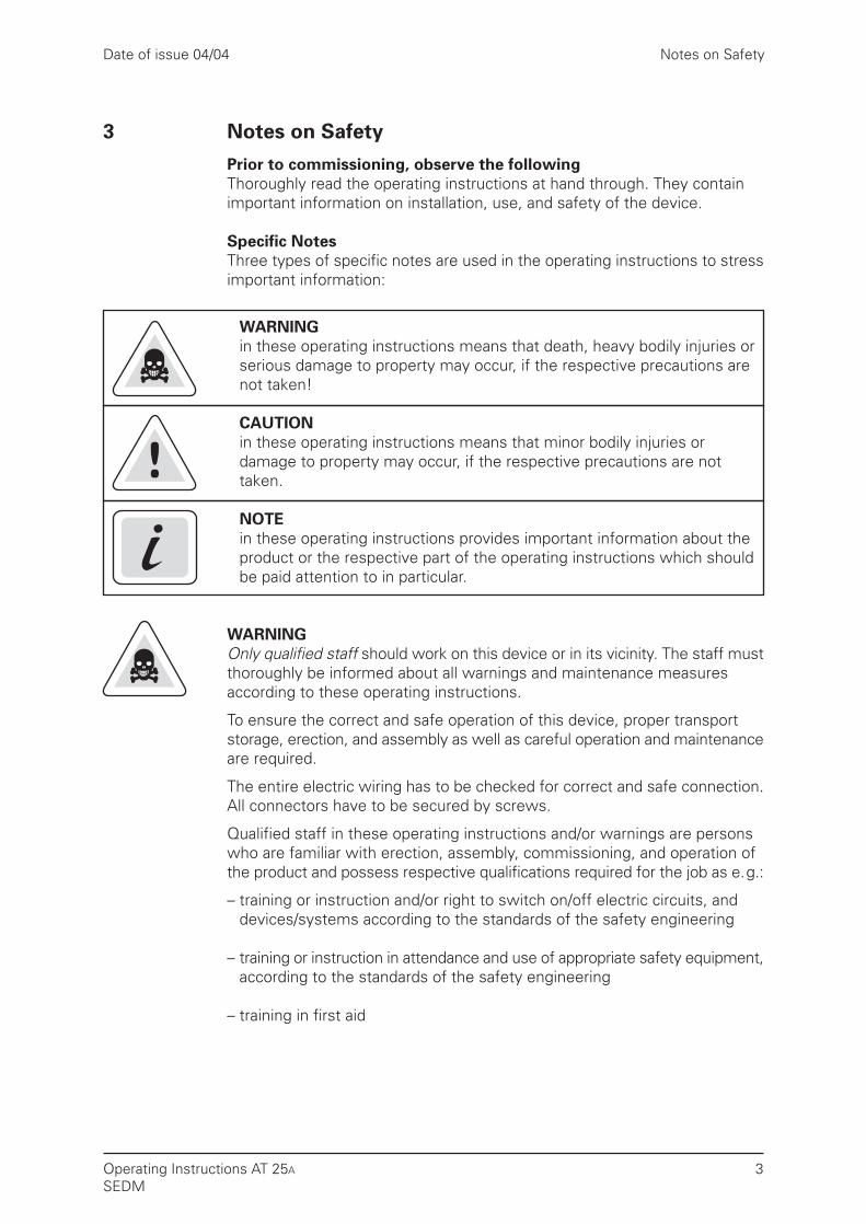
WARNINGin these operating instructions means that death, heavy bodily injuries orserious damage to property may occur, if the respective precautions arenot taken!
CAUTIONin these operating instructions means that minor bodily injuries ordamage to property may occur, if the respective precautions are nottaken.
NOTEin these operating instructions provides important information about theproduct or the respective part of the operating instructions which shouldbe paid attention to in particular.
WARNINGOnly qualified staff should work on this device or in its vicinity. The staff mustthoroughly be informed about all warnings and maintenance measuresaccording to these operating instructions.
To ensure the correct and safe operation of this device, proper transportstorage, erection, and assembly as well as careful operation and maintenanceare required.
The entire electric wiring has to be checked for correct and safe connection.All connectors have to be secured by screws.
Qualified staff in these operating instructions and/or warnings are personswho are familiar with erection, assembly, commissioning, and operation ofthe product and possess respective qualifications required for the job as e.g.:
– training or instruction and/or right to switch on/off electric circuits, anddevices/systems according to the standards of the safety engineering
– training or instruction in attendance and use of appropriate safety equipment,according to the standards of the safety engineering
– training in first aid
Date of issue 04/04
Operating Instructions AT 25A
SEDM

Overview of the Controls and Indicators
4
4 Overview of the Controls and Indicators
hand
held
ter
min
alO
N/O
FF
Date of issue 04/04
Operating Instructions AT 25A
SEDM

Functions and Device Reactions
5
5 Functions and Device Reactions
5.1 Learning and Test RunBy actuating the button DOOR-PARAM. (S-301) the automatic parameterdetermination is performed:
1. Detection of the motor type
2. Detection of the door movement direction and the position ”OPEN“
3. Determination of the door width and the position ”CLOSE“ The storing of the parameters is performed in position ”CLOSE“ and takes approx. 5 s.
5.2 DOOR-OPEN CommandWhen the DOOR-OPEN command is provided the door opens according tothe set travelling curve as long as the command is set. The transition pointsof the travelling curve (e. 9. from acceleration to steady condition) are roundedto avoid noises which may be produced through the play between the lift cardoor and the landing entrance. The door reaches the position ”OPEN“ atslow speed. Subsequently, the door is held open with a reduced moment.
– The DOOR-OPEN command must be set during the entire opening procedure.
– The DOOR-OPEN command has priority over all other control commands.
NOTEThe first opening procedure is performed at slow speed after the commis-slonlng.
5.3 DOOR-CLOSE CommandTo close the door, the DOOR-CLOSE command must be set permanently.After closing, the door is held closed with a reduced moment as long as theDOOR-CLOSE command is set.
5.4 Service ButtonsUsing the service buttons OPEN (S-302) and CLOSE (S-303) the door can beopened and closed from the control device.
Date of issue 04/04
Operating Instructions AT 25A
SEDM

Date of issue 04/04Functions and Device Reactions
6
5.5 Detection of BlockingIf the door is blocked due to an obstacle when closing, it stops and reverses.The door repeats this action maximum 5 times at the speeds of the settravelling curve. Subsequently, it switches over to slow run and tries onfinishing the closing procedure. After removal of the obstacle and completionof the closing procedure the usual door performance is reached again.
If the door is blocked when opening, it is reactivated at slow speed with 2s waiting time. The door repeats this action maximum 3 times. Should thedoor still be blocked after the third attempt, it closes at slow speed and alsoopens at slow speed when the next DOOR-OPEN command is set.
5.6 Restart after Voltage LossAfter voltage loss the door must perform a test run in direction CLOSE.It is carried out when the next DOOR-CLOSE command is set. This test runcan not be performed if the light barrier is covered (from software version1.35 on).
5.7 CLOSING FORCEThe closing force can be set between 70 and 230 N with 30 V motor andbetween 70 and 160 N with 40 V motor. If 150 N are exceeded the flashing7-segment display (IC-206) issues a warning.
CAUTIONWhen setting the closing force an active closing weight must absolutely betaken into account.
Example: Closing weight = 4 kgTurn potentiometer P-307 counterclockwise until 7-segment display(IC-206) shows ”4“ without flashing. The resulting closing forceis then 150 N.
5.8 Emergency Release
WARNINGAn emergency release can only be performed, if:
- neither a DOOR-OPEN nor DOOR-CLOSE command is set,
- the service buttons are not actuated,
- the door is at a standstill.
Only in these cases the door drive is moment-free.The force necessary for opening the door is below 300 N according toTRA- and EN81 requirement.
Operating Instructions AT 25A
SEDM

Date of issue 04/04 Funktionen und Gerätereaktionen
7
5.9 NudgingThe door does not reverse in the operating state NUDGE. The DOORCLOSEand NUDGE commands must be set simultaneously. When an obstacle isdetected the moment is revoked to the limit moment of the respective motorafter 1 s.
NOTEThis function corresponds to the requirement for fire brigade lifts accordingto TRA.
5.10 Light BarrierThe input for the light barrier signal has the same function like the DOOROPEN command. Exception: If the door is open less than 1 cm, the lightbarrier signal is ignored.
If there is no voltage at the light barrier input, this is interpreted as if the lightbarrier is covered. The door can not be closed.
If the light barrier is covered the door opens. If a DOOR-CLOSE commandis simultaneously set, the door moves in direcfion ”OPEN“ as long as thebeam is covered.
NOTEThe factory preset for the breaking slope at the interruption of the light barrieris 80%.
5.11 Emergency Electric Power SupplyIn case of mains voltage failure a battery or accumulator (e. 9. Iead-gelaccumulator) can be connected externally, thus enabling the emergencyservice.
The door can be opened and closed in this state, the light barrier input isevaluated, the speed is however limited to slow speed. If the mains voltageis available again, the controller automatically switches over to normal operation.
CAUTIONThe supply line to the external voltage source must be protected with 3.15 Aslo-blo fuse by customer.
NOTEThe voltage must be fed continuously. The charging of the accumulator mustbe performed using an external charging set.
5.12 Overload ProtectionIf the drive motor is heavily used due to frequent DOOR-OPEN and DOOR-CLOSE commands in short succession, the time of keeping open is auto-matically lengthened: the next closing procedure is delayed despite thepossibly set DOOR-CLOSE command, the 7-segment display (IC-206) shows„4“. This prevents the motor from thermal overloading.
Operating Instructions AT 25A
SEDM

Functions and Device Reactions
8
5.13 User TerminalAdditional setting and diagnosis possibilities are offered by the handheldterminal. It is connected to ST-303. The switch S-304 must be set to”TERM ON“.
The handheld terminal is available as an additional option.
NOTICEThe handheld terminal settings are overwritten if after a performed settinga parameter determination is carried out again (later) with S-301 when switchingon power supply (also refer to chapter 7 Electric Setting and Commissioning,page 10). In this case the settings are set to the delivering state. The sameis true when S-304 is set to "TERM OFF" and the CLOSE position was reached.The potentiometer settings are then taken over. These values remain stored(independent of the S-304 switch setting) until they are overwritten by thehandheld terminal again.
Date of issue 04/04
Operating Instructions AT 25A
SEDM

Mechanical Assembly and Setting
9
6. Mechanical Assembly and Setting
CAUTIONSafe operation of the lift door drive requires that it is correctly mounted andput into service by qualified staff who observe the warnings of these operatinginstructions.
Prior to all kinds of work at the door drive, make sure that the control systemis free of voltage. Only then the standstill of the door is ensured.
The mechanical assembly and setting of the lift door drive is performed infive steps:
1. Mount the motor onto the motor support (rubber-metal connection).Subsequently, mount the motor onto the assembly bracket, if necessary.
2. Mount the deflection roller, if necessary, with assembly bracket. Makesure that the driving pinion and deflection roller are aligned: they shouldprecisely face each other (be aligned).
3. Bolt the toothed belt together with the door carrier and put it on.
CAUTIONAs a door carrier (toothed belt joint) only use door carriers described in theAppendix! The inappropriate fastening may cause stress concentration onthe toothed belt that may result in destruction of the toothed belt!
The door carrier (toothed belt joint) must not run over the driving pinion orthe deflection roller!
4. Tighten the toothed belt using the tightening device until it can be pushedin approx. 3 cm in the center.
5. Mount the control device in the vicinity of the drive motor (take intoaccount the cabie length).
Date of issue 04/04
Operating Instructions AT 25A
SEDM

Electric Setting and Commissioning
10
7 Electric Setting and Commissioning
WARNINGDuring operation of electrical devices definite parts of them are inevitablyunder dangerous voltage.
If the operating instructions are not observed, heavy bodily injuries or damageto property may occur.
Especially all warnings must strictly be observed.
1. Open housing cover.
2. Plug motorplug ST-201 and ST-205.
3. Plug incremental encoder plug on ST-306 and fasten it with screws.
4. Set switch S-304 to ”TERM. OFF“ position (Preset position withouthandheld terminal).
5. Turn all potentiometers into center position.
6. Plug light barrier plug on ST-300. If the light barrier input is not used,ST-300 must be wired with ST-4 according to the lines in the generalplan.
7. Push door into position ”OPEN“.
8. Connect mains transformer with ST-1 and ST-2.
9. Connect mains transformer with mains (230 V AC).
10. Immediately after connecting the mains transformer press ”DOORPARAM“ button (S-301) until the 7-segment display (IC 206) shows”H“. It takes approx. 10 to 15 s.
11. Now the door performs a learning run. It comprises one or two openingand closing procedures in slow run over a distance of approx. 10 cm.Then the door closes at slow speed and stops in position ”CLOSE“. The7-segment display (IC 206) shows ” “.
12. The button S-302 is used now to open the door, S-303 to close the door.The first opening is always performed at slow speed; the opening iscompletely carried out, even if the button was briefly flicked. For all nextruns into positions ”OPEN“ and ”CLOSE“ which are controlled with theservice buttons S-302 and S-303, the respective button must be heldon, otherwise the run is stopped. These buttons are parallel to the OPENand CLOSE signals which are fed to ST 301.
Date of issue 04/04
Operating Instructions AT 25A
SEDM

Electric Setting and Commissioning
11
13. For special applications therun values can be adapted to the doorindividually. The following functions are available for this purpose:
Function Code designation Setting Range Potentiometer presetting (center position) at works
Maximum Vmax open P 301 0.1...0.8 m/s 50 %, 0.45 m/sopening speed
Maximum Vmax close P 302 0.1...0.8 m/s 50 %, 0.45 m/sclosing speed
Minimum Vmin P 303 0.03...0.09 m/s 50 %, 0.065 m/sspeed/slow speed
Acceleration and SLOPE P 304 0.3...1.4 m/s2 50 %, 0.85 m/s2
braking slope
Sword run in SWORD P 305 0...0.1 m 50 %, 0.05 mOPEN direction OPEN
Sword run in SWORD P 306 0...0.1 m 50 %, 0.05 mCLOSE direction CLOSE
Maximum FORCE P 307 70...230 N* 50 %, 150 Nclosing forcestatic
Slow run in OPEN SLOW P 308 0...0.1 m 50 %, 0.05 mdirection OPEN
*Only the 30 V motor reaches the value of 230 N, The 40 V motor does not exceed 160 N (automatically limited by software).
NOTEClockwise turning changes sthe setting in the direction of higher values.
Date of issue 04/04
Operating Instructions AT 25A
SEDM
Electric Setting and Commissioning
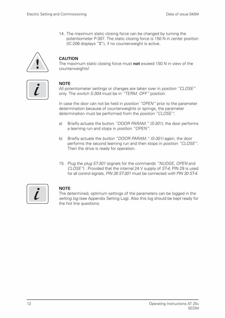
14. The maximum static closing force can be changed by turning thepotentiometer P-307. The static closing force is 150 N in center position(IC-206 displays ”O“), if no counterweight is active.
CAUTIONThe maximum static closing force must not exceed 150 N in view of thecounterweights!
NOTEAll potentiometer settings or changes are taken over in position ”CLOSE“only. The switch S-304 must be in ”TERM. OFF“ position.
In case the door can not be held in position ”OPEN“ prior to the parameterdetermination because of counterweights or springs, the parameterdetermination must be performed from the position ”CLOSE“:
a) Briefly actuate the button ”DOOR PARAM.“ (S-301), the door performsa learning run and stops in position ”OPEN“.
b) Briefly actuate the button ”DOOR PARAM.“ (S-301) again, the doorperforms the second learning run and then stops in position ”CLOSE“.Then the drive is ready for operation.
15. Plug the plug ST-301 (signals for the commands ”NUDGE, OPEN andCLOSE“) . Provided that the internal 24 V supply of ST-4, PIN 29 is usedfor all control signals, PIN 26 ST-301 must be connected with PIN 30 ST-4.
NOTEThe determined, optimum settings of the parameters can be logged in thesetting log (see Appendix Setting Log). Also this log should be kept ready forthe hot line questions.
12
Date of issue 04/04
Operating Instructions AT 25A
SEDM

Relay Contacts
13
8 Relay Contacts
The relay contacts can be used to signal the following door states to the liftcontroller:
– ST-202Door has reached the position ”CLOSE“. The relay is switched on whenthe controller has detected the position ”CLOSE“ and the incrementalencoder generates pulses no longer, i. e. the door stops.PIN 11 is connected with PIN 9 until the Door-OPEN command will be set.The relay is immediately released and PIN 11 is connected with PIN 10again.
– ST-203Door has reached the position ”OPEN“.The relay is switched on when the current distance between the door andthe position ”OPEN“ is less than 2 cm.Pin 12 and Pin 14 are then connected.If 2 cm distance is exceeded again, the relay is immediately released andPin 14 is connected with Pin 13 again.
– ST-204The door reverses.The relay is switched on when the door reverses e. g. due to blocking.The relay is also switched on if a DOOR-OPEN command is set, or the lightbarrier is covered during the closing procedure.Pin 15 is then connected with Pin 17.
In the ”Overview of Controls and Indicators“ the contacts are shown in idlestate.
Date of issue 04/04
Operating Instructions AT 25A
SEDM

Travelling Curve
14
9 Travelling Curve
NOTEThe values for ”Vmin OPEN“ and ”Vmin CLOSE“ can only be adjusted separatelyby using the handheld terminal.
Open
Close
Sword OPEN
Sword CLOSE
Slope
Slope
Vmin OPEN
Vmin CLOSE
Vmax OPEN
Vmax CLOSE
Vmin OPEN
Vmin CLOSE
Slope
Slope
Slow OPEN
Path
Date of issue 04/04
Operating Instructions AT 25A
SEDM

Display of Operating State
15
10 Display of Operating State
The 7-segment display IC-206 shows following operating states:
Display Meaning
0 Light barrier signal is set
1 RAM, EPROM or CPU error
2 EEPROM error
3 error in AD converter
4 Extra time for keeping open when motor operating time is increased
5 error ASIC serial
6 Motor is blocked
7 Error incremental encoder
8 Starting test (approx. 10 s) is not finished yet or control system is defective
9 Motor overcurrent
A Door is stopped during the first run by OPEN signal or light barrier
C Threefold blocking when opening
E Motor overvoltage
F Motor undervoltage
H Parameter determination
L Error of current measurement
Function O. K.
P Parameter error
Door is closed
Date of issue 04/04
Operating Instructions AT 25A
SEDM

11 Speed Limit Curve
The speed limit curve is a characteristic line for determination of the max.permissible door speed Vmax depending on the overall door mass.
According to EN 81 the maximum kinetic energy of the door in a closingdirection must not exceed 10 Joule. WKIN = 1/2 m v2 ≤ 10 J.
Example from the following speed limit curve:Overall door mass m = 250 kg => Vmax = 0,28 m/s.
NOTEThe speed can be set between 0 (corresponds to 0.10 m/s) and100 % (corresponds to 0.80 m/s).
40 V motor reaches maximum 71 % (corresponds 0.60 m/s),30 V motor reaches maximum 85 % (corresponds 0.70 m/s).
Speed Limit Curve
16
m (kg)Overall door leaf mass
Vmax (m/s)
Impermissible range
1.00
0.80
0.70
0.60
0.50
0.40
0.30
0.20
0.10
0.90
50 100 150 200 250 300 350 400 450 500
Date of issue 04/04
Operating Instructions AT 25A
SEDM
Technical Data
17
Date of issue 04/04
Operating Instructions AT 25A
SEDM
12 Technical Data
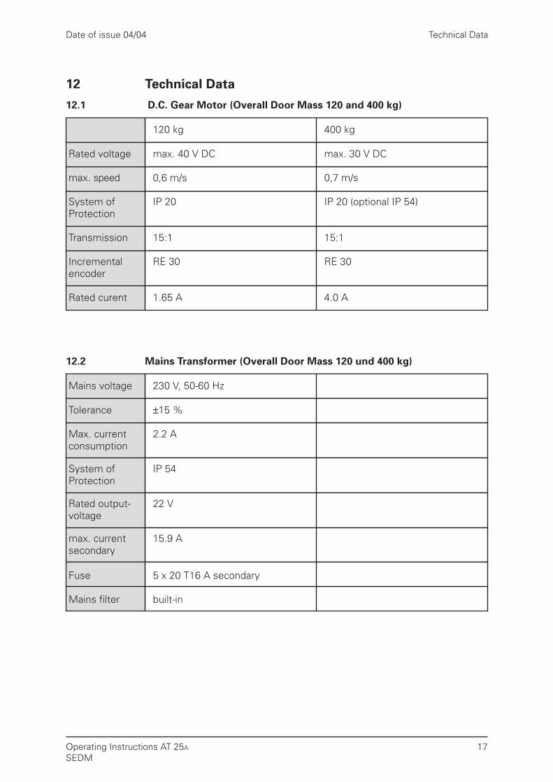
12.1 D.C. Gear Motor (Overall Door Mass 120 and 400 kg)
120 kg 400 kg
Rated voltage max. 40 V DC max. 30 V DC
max. speed 0,6 m/s 0,7 m/s
System of IP 20 IP 20 (optional IP 54)Protection
Transmission 15:1 15:1
Incremental RE 30 RE 30encoder
Rated curent 1.65 A 4.0 A
12.2 Mains Transformer (Overall Door Mass 120 und 400 kg)
Mains voltage 230 V, 50-60 Hz
Tolerance ±15 %
Max. current 2.2 Aconsumption
System of IP 54Protection
Rated output- 22 Vvoltage
max. current 15.9 Asecondary
Fuse 5 x 20 T16 A secondary
Mains filter built-in
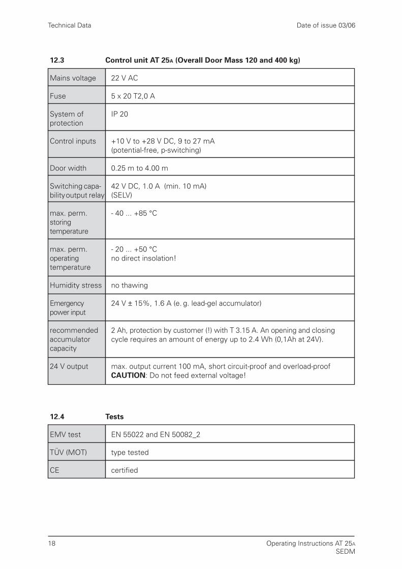
12.3 Control unit AT 25A (Overall Door Mass 120 and 400 kg)
Mains voltage 22 V AC
Fuse 5 x 20 T2,0 A
System of IP 20protection
Control inputs +10 V to +28 V DC, 9 to 27 mA(potential-free, p-switching)
Door width 0.25 m to 4.00 m
Switching capa- 42 V DC, 1.0 A (min. 10 mA)bility output relay (SELV)
max. perm. - 40 ... +85 °Cstoringtemperature
max. perm. - 20 ... +50 °Coperating no direct insolation!temperature
Humidity stress no thawing
Emergency 24 V ± 15%, 1.6 A (e. g. lead-gel accumulator)power input
recommended 2 Ah, protection by customer (!) with T 3.15 A. An opening and closingaccumulator cycle requires an amount of energy up to 2.4 Wh (0,1Ah at 24V).capacity
24 V output max. output current 100 mA, short circuit-proof and overload-proofCAUTION: Do not feed external voltage!
Technical Data
18
Date of issue 03/06
Operating Instructions AT 25A
SEDM
12.4 Tests
EMV test EN 55022 and EN 50082_2
TÜV (MOT) type tested
CE certified

Appendix
19
13 Appendix
13.1 Appendix 1:Ident. Numbers of the Individual Parts
Ident. Nr. Plain Text Code Designation
Control Device
10005711 AT 25A, incl. mains transformer AT 25A
Gear Motor
10005250 40 V motor, pinion left, doors up to 120 kg AT1-40-120-L
10004691 40 V motor, pinion right, doors up to 120 kg AT1-40-120-R
10005678 30 V motor, pinion left, doors up to 400 kg AT2-30-300-L
10005677 30 V motor, pinion right, doors up to 400 kg AT2-30-300-R
Accessories
070220808 Rubber-metal connection support 40 V motor AT 1 rubber-metalconnection
070220794 Rubber-metal connection support 30 V motor AT 2 rubber-metalconnection
070220816 Assembly bracket for gear motor Assembly bracket(both motors) for motor
070220824 Assembly bracket with tightening device Assembly bracketfor deflection roller for deflection roller
070040052 Door carrier, 2 pieces
070040060 Deflecting device (both motors)
070220352 Incremental encoder cable (both motors)
070040028 Toothed belt 4 m (both motors)
070040087 Toothed belt 45 m (both motors)
Date of issue 04/04
Operating Instructions AT 25A
SEDM

Appendix
20
13.2 Appendix 2:
Dimension Sheet Control Device AT 25A
Date of issue 04/04
Operating Instructions AT 25A
SEDM

Appendix
21
13.3 Appendix 3:
Dimension Sheet Mains Transformer AT 25A
Sch
ock-
proo
f pl
ug
Leng
th: a
ppro
x. 1
.8 m
Ant
ikin
k bu
sh
3333
Ant
ikin
k bu
sh
Leng
th: a
ppro
x. 1
.4 m
Con
nect
ion
to A
T25A
11
Fuse
ø 1
25 m
m72
mm
hig
h
Date of issue 04/04
Operating Instructions AT 25A
SEDM

Gear motor (left)
Motor support (rubber-metal connection)
4 x safety hexagon screw M5 x 10
7 x safetyhexagon screw M6 x 16
Assembly bracketMotor support
Gear motor (left)
Mea
n to
othe
d be
lt di
stan
ce
Appendix
22
13.4 Appendix 4:
40 V Gear Motor, Driving Pinion Left,with Rubber-Metal Connection and Assembly Bracket
Date of issue 04/04
Operating Instructions AT 25A
SEDM

Appendix
23
13.5 Appendix 5:
30 V Gear Motor, Driving Pinion Right,with Rubber-Metal Connection and Assembly Bracket
Motor support (rubber-metal connection)
7 x safetyhexagon screw M6 x 16
6 x safety hexagon screw M6 x 10
Assembly bracketMotor support
Gear motor (right)
Gear motor (right)
Date of issue 04/04
Operating Instructions AT 25A
SEDM

Appendix
24
13.6 Appendix 6:
Deflection Roller with Tightening Device and Assembly Bracket
Deflecting device AT 20
Tension web
Tightening screwM6 x 50 DIN 933
3 x safetyhexagon screw M6 x 16
Assembly bracketTightening device
Assembly bracketTightening device
Tension web
Tightening screwM6 x 50 DIN 933
2 x hexagon screw M6 x 12 DIN 9332 x plain washer 6.4 DIN 125
Tightening range
Mea
n to
othe
d be
lt di
stan
ce
Deflecting device
2 x hexagon screw M6 x 12 DIN 9332 x plain washer 6.4 DIN 125
Date of issue 04/04
Operating Instructions AT 25A
SEDM

Appendix
25
13.7 Appendix 7:
Door Carrier
Lock
ing
scre
w M
6
Lock
ing
scre
w
Doo
r ca
rrie
rno
t su
pplie
d
Cla
mpi
ng p
late
Hol
der
carr
ier
STS
too
thed
bel
tH
olde
r C
arrie
r
STS
too
thed
bel
t
Cla
mpi
ng p
late
Date of issue 04/04
Operating Instructions AT 25A
SEDM
Mot
or s
uppo
rtco
mpl
ete
(not
dra
wn)
Doo
r
leav
es
open
doo
r
c
lose
d
Fast
enin
g m
eans
for
door
car
rier
Def
lect
ing
and
tight
enin
g de
vice
Tigh
teni
ng s
crew
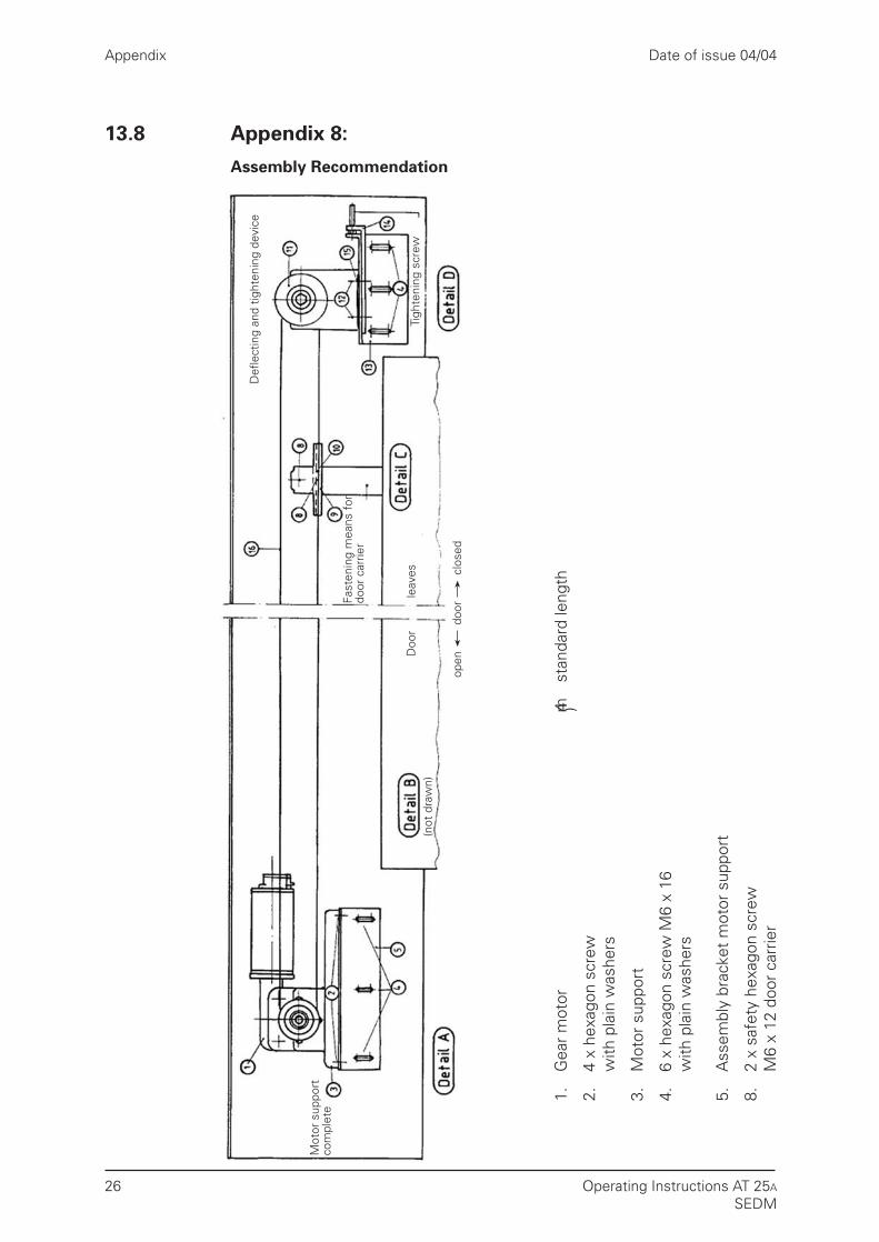
1.G
ear
mot
or
2.4
x he
xago
n sc
rew
with
pla
in w
ashe
rs
3.M
otor
sup
port
4.6
x he
xago
n sc
rew
M6
x 16
with
pla
in w
ashe
rs
5.A
ssem
bly
brac
ket
mot
or s
uppo
rt
8.2
x sa
fety
hex
agon
scr
ewM
6 x
12 d
oor
carr
ier
4mst
anda
rd le
ngth
)
Appendix
26
13.8 Appendix 8:
Assembly Recommendation
Date of issue 04/04
Operating Instructions AT 25A
SEDM

Appendix
27
13.9 Appendix 9:
Wiring Diagram Control Inputs
ST 4
ST 300
ST 301
from the controller+10 V to +28 V DC
9 mA to 27 mA
+-
Light barrier
or bridged
OPEN
CLOSE
Nudge
30
29
28
27
26
25
24
23
OPEN
CLOSE
Nudge
-
+
-
Light barrier
or bridged
OPEN
CLOSE
Nudge
30
29
28
27
26
25
24
23
OPEN
CLOSE
Nudge
-
+
-
Connection to internal 24 V control voltage Connection to external control voltage
Nudge = CLOSE and Nudge commands simultaneously
-
+
24 V100 mA
Date of issue 04/04
Operating Instructions AT 25A
SEDM
Appendix
28
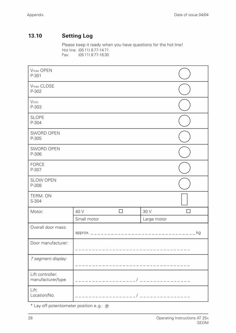
13.10 Setting Log
Please keep it ready when you have questions for the hot line!Hot line: (05 11) 8 77-14 71Fax: (05 11) 8 77-16 30
Potentiometer Position *
Vmax OPENP-301
Vmax CLOSEP-302
Vmin
P-303
SLOPEP-304
SWORD OPENP-305
SWORD OPENP-306
FORCEP-307
SLOW OPENP-308
TERM. ONS-304
Motor: 40 V 30 V
Small motor Large motor
Overall door mass:approx. _ _ _ _ _ _ _ _ _ _ _ _ _ _ _ _ _ _ _ _ _ _ _ _ _ _ _ _ _ _ _ kg
Door manufacturer:_ _ _ _ _ _ _ _ _ _ _ _ _ _ _ _ _ _ _ _ _ _ _ _ _ _ _ _ _ _ _ _ _ _
7 segment display:_ _ _ _ _ _ _ _ _ _ _ _ _ _ _ _ _ _ _ _ _ _ _ _ _ _ _ _ _ _ _ _ _ _
Lift controller:manufacturer/type _ _ _ _ _ _ _ _ _ _ _ _ _ _ _ _ _ _ / _ _ _ _ _ _ _ _ _ _ _ _ _ _ _
LiftLocation/No. _ _ _ _ _ _ _ _ _ _ _ _ _ _ _ _ _ _ / _ _ _ _ _ _ _ _ _ _ _ _ _ _ _
* Lay off potentiometer position e.g.:
Date of issue 04/04
Operating Instructions AT 25A
SEDM


Siemens Aktiengesellschaft© Siemens AG 2006 All Rights ReservedPrinted in Germany
Contact
Siemens AGElectronic Design andManufacturing Services(I&S EDM)
Am Brabrinke 14D-30519 Hannover
Telefon +49 (40) 28 89-43 22Telefax +49 (511) 877-16 30E-Mail: [email protected]/edm