Embed Size (px)
Citation preview

JET 427 New Sanford Road LaVergne, Tennessee 37086 Document No. M-140233 Ph.: 800-274-6848 Edition 1 07/2020 www.jettools.com Copyright © 2020 JET
Operating Instructions and Parts Manual TS Series 2-speed Electric Chain Hoists
single fall model shown
2
1.0 IMPORTANT SAFETY INSTRUCTIONS
WARNING: To avoid risk of injury:
1. Read and understand the entire owner's manual before attempting assembly or operation.
2. Read and understand the warnings posted on the machine and in this manual. Failure to comply with all of these warnings may cause serious injury.
3. Replace warning labels if they become obscured or removed.
4. This chain hoist is designed and intended for use by properly trained and experienced personnel only. If you are not familiar with the proper and safe operation of a chain hoist, do not use until proper training and knowledge have been obtained.
5. Do not use this chain hoist for other than its intended use. If used for other purposes, JET disclaims any real or implied warranty and holds itself harmless from any injury that may result from that use.
6. Do not install this chain hoist where explosive hazards may exist.
7. Give your work undivided attention. Looking around, carrying on a conversation and “horse-play” are careless acts that can result in serious injury.
8. Do not use to lift people, or loads over people. Warn others in the vicinity when lifting or transporting a load. Avoid swinging load and hook.
9. Do not exceed the rated lift capacity of the chain hoist.
10. Make sure limit switches are operating properly. Do not use limit switches as routine operating stops; they are emergency devices only.
11. Verify that load chain is properly seated in load sheeve before operating hoist.
12. Do not use the load chain as a sling, or wrap load chain around the load.
13. Do not use the load chain to side-pull a load.
14. Always inspect the chain hoist for damage prior to use. Do not use a chain hoist with twisted, kinked, worn or otherwise damaged chain. If the chain hoist is damaged, do not use until it has been repaired or replaced.
15. Do not use more than one chain hoist to lift or move a load. If this is unavoidable, each chain hoist must have the same capacity as the load to be moved.
16. Never allow the load chain to “set” over sharp edges. All lifts must be made with straight chain that is free of obstacles.
17. Do not use chain hoist unless load is centered between top and bottom hooks.
18. Protect load chain from weld splatter and other contaminants. Do not allow the hook or chain to be contacted by a live welding electrode.
19. Always take time to study the job to be performed and choose the safest method. Do not place yourself or other people in an unsafe position. Maintain constant awareness of the lifting environment.
20. Leave all internal maintenance to a qualified JET service center.
21. Disconnect hoist from power source before performing maintenance or opening the housing.
22. Do not leave a suspended load unattended.
23. Replace the chain with factory replacement chain only. Do not use any other type of chain.
24. Never use the chain hoist if either hook is stretched, deformed, or has a broken or missing safety latch. Always replace the safety latch and/or the hook before placing the chain hoist back into service.
25. Keep safety guards in place at all times when the hoist is in use.
26. Do not operate this hoist while tired or under the influence of drugs, alcohol or any medication.
27. This hoist is not designed for exposure to outdoor elements.
28. Understand and follow all procedures as set forth in American National Standards titled Overhead Hoists (Underhung), ANSI/ASME B30.16. This standard is available through the American Society of Mechanical Engineers at www.ASME.org.

3
Familiarize yourself with the following safety notices used in this manual:
This means that if precautions are not heeded, it may result in minor injury and/or possible machine damage.
This means that if precautions are not heeded, it may result in serious injury or possibly even death.
2.0 Important notice It is the responsibility of the owner/user to install, inspect, operate and maintain this hoist in accordance with OSHA regulations and ANSI/ASME B30.16, “Overhead Hoists (Underhung)”, along with any state or local codes/ordinances as applicable. If hoist is installed as part of a total lifting system (trolley, crane, monorail, etc.), or if below-the-hook lifting devices will be used, it is the responsibility of the owner/user to comply with any standards or regulations involving those additional elements of the system.
3.0 About this manual This manual is provided by JET covering the safe operation and maintenance procedures for the JET TS series hoists. This manual contains instructions on installation, safety precautions, general operating procedures, maintenance instructions and parts breakdown for your hoist. It is not intended to be an exhaustive guide to the use of hoists or the broad subject of rigging, and cannot anticipate every system or lifting configuration in which this product may be used.
Retain all instructions and safety warnings for continued reference. If the hoist transfers ownership, the manual should accompany it.
If there are questions or comments, please contact either your local supplier or JET. JET can also be reached at our web site: www.jettools.com.
Read and understand the entire contents of this manual before installing hoist or attempting operation, adjustment or maintenance. Failure to comply may cause serious injury.
WARNING: This product can expose you to chemicals including lead and cadmium which are known to the State of California to cause cancer and birth defects or other reproductive harm, and phthalates which are known to the State of California to cause birth defects or other reproductive harm. For more information go to http://www.p65warnings. ca.gov.

4
4.0 Table of contents Section Page 1.0 IMPORTANT SAFETY INSTRUCTIONS ....................................................................................................... 2 2.0 Important notice ............................................................................................................................................. 3 3.0 About this manual .......................................................................................................................................... 3 4.0 Table of contents ............................................................................................................................................ 4 5.0 Product introduction ....................................................................................................................................... 5 6.0 Glossary ......................................................................................................................................................... 5 7.0 TS series hoist specifications ......................................................................................................................... 6
7.1 TS series hoist dimensions with MT trolley ................................................................................................ 7 7.2 Operating environment ............................................................................................................................... 7
8.0 Unpacking ...................................................................................................................................................... 8 9.0 Installation ...................................................................................................................................................... 8
9.1 Mounting top hook ...................................................................................................................................... 8 9.2 Power cable ................................................................................................................................................ 8 9.3 Lubrication .................................................................................................................................................. 9 9.4 Chain container .......................................................................................................................................... 9
10.0 Electrical connections .................................................................................................................................. 9 10.1 GROUNDING INSTRUCTIONS ............................................................................................................... 9 10.2 Inspecting hoist motion ........................................................................................................................... 10
11.0 Pre-operation inspection .................................................................................................................................. 10 11.1 Inspecting load chain .............................................................................................................................. 10 11.2 Inspecting hooks .................................................................................................................................... 10
12.0 Operation ................................................................................................................................................... 11 12.1 Controls .................................................................................................................................................. 11 12.2 General procedure ................................................................................................................................. 11 12.3 Magnetic brake function ......................................................................................................................... 12
13.0 Adjustments ............................................................................................................................................... 12 13.1 Replacing load chain .............................................................................................................................. 12 13.2 Limit switch adjustments ........................................................................................................................ 14
14.0 Mechanical classification (grade) ............................................................................................................... 15 15.0 Inspection and maintenance ...................................................................................................................... 16
15.1 Gearbox oil ............................................................................................................................................. 16 16.0 Inspection schedules .................................................................................................................................. 17 17.0 Allowable limits ........................................................................................................................................... 18
17.1 Hook wear limits (top and bottom) .......................................................................................................... 18 17.2 Chain wear limits .................................................................................................................................... 19
18.0 Chain container selection for TS series hoist ............................................................................................. 20 19.0 Pendant controllers for TS hoists ............................................................................................................... 20 20.0 Troubleshooting TS series Hoist ................................................................................................................ 21 21.0 Replacement Parts ..................................................................................................................................... 22
21.1.1 TS050,TS100 Motor Assembly and Housing – Exploded View .......................................................... 23 21.1.2 TS050,TS100 Motor Assembly and Housing – Parts List ................................................................... 24 21.2.1 TS050, TS100 Hook Assembly – Exploded View ............................................................................... 26 21.2.2 TS050, TS100 Hook Assembly – Parts List ........................................................................................ 27 21.3.1 TS050, TS100 Load Chain – Exploded View ...................................................................................... 28 21.3.2 TS050, TS100 Load Chain – Parts List ............................................................................................... 29 21.4.1 TS050, TS100 Gear Box – Exploded View ......................................................................................... 30 21.4.2 TS050, TS100 Gear Box – Parts List .................................................................................................. 31 21.5.1 TS050, TS100 Electrical Assembly – Exploded View ......................................................................... 34 21.5.2 TS050, TS100 Electrical Assembly – Parts List .................................................................................. 35 21.6.1 TS200,TS300,TS500 Motor Assembly and Housing – Exploded View ............................................... 36 21.6.2 TS200,TS300,TS500 Motor Assembly and Housing – Parts List ........................................................ 37 21.7.1 TS200,TS300,TS500 Hook Assembly – Exploded View ..................................................................... 38 21.7.2 TS200,TS300,TS500 Hook Assembly – Parts List .............................................................................. 39 21.8.1 TS200,TS300,TS500 Gear Box – Exploded View ............................................................................... 40 21.8.2 TS200,TS300,TS500 Gear Box – Parts List ....................................................................................... 41 21.9.1 TS200,TS300,TS500 Electric Assembly – Exploded View ................................................................. 42 21.9.2 TS200,TS300,TS500 Electric Assembly – Parts List .......................................................................... 43
22.0 Electrical connections for TS Hoist ............................................................................................................ 44 23.0 Warranty and Service ................................................................................................................................. 46

5
5.0 Product introduction Your JET dual-speed hoist is designed and constructed to provide consistent, long-term operation if used in accordance with the instructions set forth in this manual.
JET TS series hoists are available in 230 volt, 3-phase power, as well as varied chain lengths.
The magnetic disc brake provides dependable and rapid stopping of chain movement without hook drift, and produces less wear on brake elements than standard mechanical braking systems, thus reducing maintenance. The hoist is equipped with upper and lower limit switches, and a slip-clutch to prevent overloading.
This hoist complies with FEM standards.
6.0 Glossary Key terms helpful to the hoist operator:
Creep speed: Slow, constant, fixed rate of motion of a hoist.
Duty cycle: The amount of work a hoist can perform in a given period of time, generally measured by maximum run time and number of starts within that period. Duty cycle ratings are designated H1 through H5.
Duty class: Identifies the type of service for which a hoist is designed, designated A through F.
Headroom: Minimum distance between saddle of top hook to saddle of load hook, measured when load hook is at upper travel limit. Smaller headroom allows a hoist to fit in tighter work spaces.
Hook saddle: The inside arc of the hook which contacts the beam (top hook) or where the load sling is seated (load hook).
Toggle or “bump fire”: Rapid press and release of a control button to raise or lower load in intermittent steps. (A variable frequency drive in lowest speed range often eliminates the need for toggling.)
Overtravel limit device: A device for limiting upward or downward travel of the load hook at the extremities of its lift. (If activation of the device alters the electrical circuit within the machine, it is often called a “limit switch.”)
Load block: The assembly of hook or shackle, swivel, bearing, pins, sheaves and frame suspended by the chain.
Electro-magnetic brake: A stopping device controlled by the application of electrical current to the coil of an electromagnet, which draws away an armature allowing rotation of the shaft. When the magnet is de-energized, the armature moves back toward the brake face and squeezes together friction discs – the torque is applied to the hub and stops shaft rotation.
Overload limit device: A mechanical or electrical device that prevents the hoist from lifting when excessive load is applied.
Rated Load, or Capacity: The maximum load weight, usually labeled as tonnage, which the hoist is designed to handle as designated by the manufacturer.
Reeving: The system in which a chain or rope travels around a running sheave.
Running Sheave: A sheave which engages the chain/rope and rotates as the load block is raised or lowered. Also called “load sheave” or “load sprocket.”

6
7.0 TS series hoist specifications The specifications in this manual were current at time of publication, but because of our policy of continuous improvement, JET reserves the right to change specifications at any time and without prior notice, without incurring obligations.
Figure 7-1
TS050 TS100 TS200 TS300 TS500
Capacity 1/2 ton (500 kg) 1 ton (1000 kg) 2 ton (2000 kg) 3 ton (3000 kg) 5 ton (5000 kg)
Lift All models available in standard 10, 15 or 20 ft. lifts.
Custom lengths available up to 100 ft. for most models 1
Load Chain (diameter x pitch)
in. Ø .248 x .752 Ø .280 x .795 Ø .394 x 1.189 Ø .394 x 1.189 Ø .441 x 1.339 mm Ø 6.3 x 19.1 Ø 7.1 x 20.2 Ø 10 x 30.2 Ø 10 x 30.2 Ø 11.2 x 34
Number of falls 1 1 1 2 2
Lifting speeds (ft/min)
High spd 33 26 32 21 13
Low spd 8 7 8 5 3
Pendant controls Dependent upon lift and trolley use; see sect. 18.0.
Duty Cycle
Time Rating 30 min. Intermittent
Duty % 40/20
Max. starts per hour
240
Motor
Horsepower High 1.5 2 5 5 5 Low 0.4 0.5 1.2 1.2 1.2
Pole 2/8 Cycle 60 Hz Phase 3 Voltage 220
Current Draw (amperage)
High spd. 6.9 11 16.8 16.8 16.8 Low spd. 4 5.6 8.4 8.4 8.4
Noise level 2 75 db Gearbox capacity 1.2 L 1.4L 4L 4L 4L
Dimensions (Figure 7-1)
A 22-7/16" (570mm) 24-7/16" (620mm) 28-1/8" (715mm) 28-1/8" (715mm) 28-1/8" (715mm) B 10-5/8" (270mm) 11-13/16" (300mm) 13-3/8" (340mm) 13-3/8" (340mm) 13-3/8" (340mm)
C 12-3/16" (310mm) 12-5/8" (320mm) 14-3/4" (375mm) 14-3/4" (375mm) 14-3/4" (375mm)
D 6-1/2" (165mm) 7-1/16" (180mm) 8-11/16" (220mm) 8-11/16" (220mm) 8-11/16" (220mm) E 14-3/4" (375mm) 16-1/8" (410mm) 20-7/8" (530mm) 20-7/8" (530mm) 20-7/8" (530mm) F 7-1/2" (190mm) 7-11/16" (195mm) 10-5/8" (270mm) 10-5/8" (270mm) 10-5/8" (270mm) G 7-5/16" (185mm) 8-11/16" (220mm) 10-1/4" (260mm) 10-1/4" (260mm) 10-1/4" (260mm) H1 19-11/16" (500mm) 21-5/8" (550mm) 40-3/16" (1020mm) ----- ----- H2 ----- ----- ----- 41-5/16" (1050mm) 43-5/16" (1100mm)
Table 1
7
1 Stock numbers vary based upon chain length. Determine needs, then see JET website for stock numbers. 2 Measured at 1m horizontally from hoist during normal operation. The specified values are emission levels and are not necessarily to be seen as safe operating levels. As workplace conditions vary, this information is intended to allow the user to make a better estimation of the hazards and risks involved only.
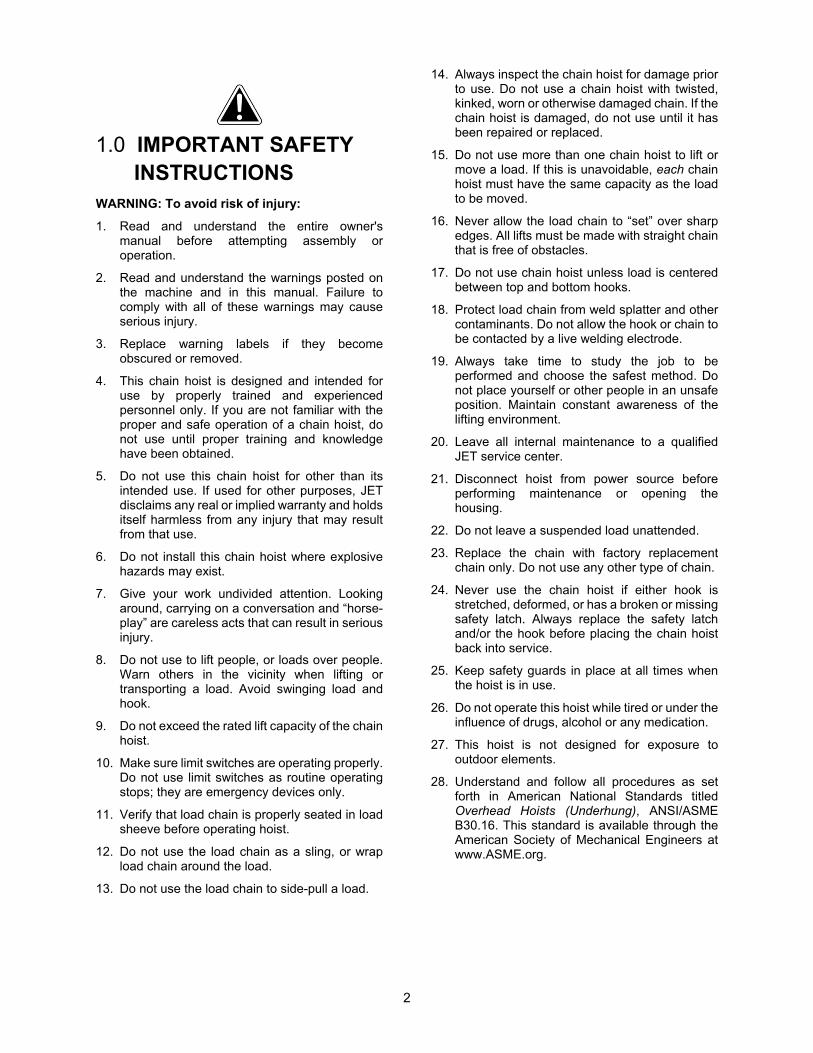
7.1 TS series hoist dimensions with MT trolley
MT Trolleys (purchased separately) are designed to pair with the TS hoists. See trolley manual for instructions on connecting the two.
Figure 7-2
TS050 TS100 TS200 TS300 TS500
Trolley model no. MT050 MT100 MT200 MT300 MT500
stock no. 140183 140185 140187 140189 140190
A 15-3/16" (385mm) 15-3/16" (385mm) 15-9/16" (395mm) 17-1/2" (445mm) 17-1/2" (445mm)
B 4-15/16" (126mm) 4-15/16" (126mm) 6-1/4" (159mm) 7-5/16" (185mm) 7-5/16" (185mm)
C 12-13/16" (325mm)
12-13/16" (325mm)
14-3/16" (360mm) 15-3/4" (400mm) 15-3/4" (400mm)
D 7-1/16" (180mm) 7-1/16" (180mm) 7-5/16" (185mm) 7-11/16" (195mm) 7-11/16" (195mm)
E* 2-15/16~4-15/16"
(75~125mm) 2-15/16~4-15/16"
(75~125mm) 3-15/16~5-7/8" (100~150mm)
4-15/16~6-7/8" (125~175mm)
4-15/16~6-7/8" (125~175mm)
H1 19-11/16" (500mm)
21-1/16" (535mm) 38-3/16" (970mm) ----- -----
H2 ----- ----- ----- 39-3/8" (1000mm) 41-5/16"
(1050mm)
Table 2
* The trolley can be extended for greater “E” widths than what are shown in the chart. See trolley manual for details.
7.2 Operating environment
Working temperature range: -5 to +40 °C (23 to 104 °F)
Working humidity range: 85% or less
Electric power supply: 3 phase, 60Hz, 220V

8
Read and understand the entire contents of this manual before installing hoist or attempting operation. Failure to comply may cause serious injury.
8.0 Unpacking Remove hoist from its crate and carefully inspect its components for shipping damage. Report any damage immediately to your distributor and shipping agent. Do not discard any shipping material until hoist is installed and running properly.
Contents of shipping crate
1 Electric chain hoist 1 Chain container with fasteners 1 Power supply cord 1 Pendant control 1 Chain gauge (attached to pendant cord) 1 Top hook assembly 1 Bottom hook assembly with chain 1 Operating instructions & parts manual 1 Product registration card 1 Test certificate
9.0 Installation Support for the hoist may be hook, clevis pin, trolley, or beam clamp. Whatever method of suspension is chosen, the support components must be rated equal to, or greater than the capacity of the chain hoist. Supporting structures (such as I-Beams) should be installed by properly licensed professional installers.
If you are using the hoist with a trolley, refer to the trolley manual for instructions on securing the control cord and maintaining proper slack in the cord during operation. Optional pendant cords for use with a trolley system are shown in section 18.0
TIP: If suspending from a trolley, it may be easier to remove top hook from hoist and attach it to trolley load plate, then re-attach hoist to the hook.
Make sure the suspension system used is properly grounded, in addition to the grounding of the hoist.
9.1 Mounting top hook
If the TS-series hoist will be used without a trolley, attach the top hook with the provided pin(s), lock washer(s), hex nut(s) and cotter pin(s).
If the TS-series hoist will be used with a JET MT trolley, do not attach the top hook. Instead mount the hoist to the trolley bottom using the provided fasteners through the aligned holes. See Trolley manual.
9.2 Power cable
All electrical connections must be made by qualified personnel. Read sect. 10.0 before connecting this unit to power.
Hoist only: Connect the power cable leads to an extension and run the line to the electrical panel, or install a UL/CSA approved plug to draw from a receptacle.
Hoist with MT trolley: The trolley will draw its power through the hoist. Connect trolley cable to hoist. Then direct hoist cable to the power source. See trolley manual for instructions.
IMPORTANT: The power cable should be directed so that it is safely out of the way of loads. If a trolley is used, power cable must not interfere with, or be pinched by, trolley travel. See Figure 9-1 for a recommended solution.
Figure 9-1

9
9.3 Lubrication
9.3.1 Gear oil
Your hoist has been shipped with oil included in the gearbox. Before operating, verify the oil level by removing the fill plug on top of the hoist, shown in Figure 9-2. The oil level should be just below the edge of the hole.
Check the level again after the first 500 hours of operation, then check every 3 months. See sect. 14.1 for oil specifications.
IMPORTANT: Before operating hoist, pull out the rubber breather plug from the top fill plug (Figure 9-2). Reinsert this plug if hoist is to be transported or placed in storage.
Figure 9-2
9.3.2 Chain lubrication
Periodically apply a light coat of 30W oil to the chain. This will create easier operation and prolong the chain’s life. For optimum results, clean chain with an acid-free solution before oiling.
9.4 Chain container
Your hoist is supplied with a chain container designed to fit the particular length of chain. If a different length chain is ever installed on this hoist, the chain container must be replaced by one of proper size. See chart in sect. 17.0.
The chain container should be installed after the power supply is connected to hoist.
Do not overfill chain container. If chain should overfill and begin to fall, entire chain container may empty without warning, resulting in serious personal injury or property damage.
To assemble chain container to hoist:
1. Hang hoist in position on the I-Beam or trolley. Do not install chain container yet. Allow slack side and load side of chain to hang freely from hoist.
2. Apply power to hoist and press DOWN button until limit switch is tripped.
3. Mount chain container to hoist undercarriage, using two bolts with lock nuts See Figure 9-3.
4. Place chain stop into container, and operate hoist to bring load hook up until upper limit switch is tripped.
5. Inspect chain to ensure that all non-loaded chain is completely in container.
Do not dump chain by hand into the chain container. By not following the above steps, the chain can become twisted or kinked and can damage the hoist.
Figure 9-3
10.0 Electrical connections
Electrical connections must be made by a qualified electrician in compliance with all relevant codes. This machine must be properly grounded to help prevent electrical shock and possible fatal injury.
The TS series hoist is pre-wired for 220V, 3-phase power only.
The hoist should be connected to a circuit with current overload protection, rated at minimum 120% of the full load amperage listed on the hoist’s nameplate. If fuses are used, they must be time-delay fuses rated “D”. Local codes take precedence over recommendations.
10.1 GROUNDING INSTRUCTIONS
In the event of a malfunction or breakdown, grounding provides a path of least resistance for electric current to reduce the risk of electric shock.
This hoist is not supplied with a power plug. Power supply cables may either be fitted with a UL/CSA-listed plug rated for the appropriate phase and voltage, or “hard-wired” directly to a control panel. If hard-wired, make sure a disconnect is available for the operator.
If a plug is installed, it must have an equipment-grounding conductor and a grounding prong. The plug must be plugged into a matching outlet that is properly installed and grounded in accordance with all local codes and ordinances.

10
Do not modify the plug – if it will not fit the outlet, have the proper outlet installed by a qualified electrician.
Improper connection of the equipment-grounding conductor can result in a risk of electric shock. The conductor with insulation having an outer surface that is green with or without yellow stripes is the equipment-grounding connector.
If repair or replacement of the electric cord or plug is necessary, do not connect the equipment-grounding conductor to a live terminal.
Check with a qualified electrician or service personnel if the grounding instructions are not completely understood, or if in doubt as to whether the tool is properly grounded.
Repair or replace damaged or worn cord immediately.
10.2 Inspecting hoist motion
1. Before closing circuit breaker and testing hoist, check that wiring has been complete. If hoist cannot be observed when circuit breaker is closed, station an observer within sight of hoist to report any movement when power is applied. Be prepared to disconnect power if hoist motor starts when power is applied – the hoist must remain motionless when power is applied. Find and correct any problems before continuing.
2. With no load on load hook, press UP button very briefly and observe hoist action. The hook should move upward.
3. On hoists with 3-Phase power supply, if the hook moves in opposite direction to that shown on control button, or if no motion occurs when UP button is pressed, then the power supply wires are incorrectly positioned.
Disconnect hoist from power, and switch any two of the three supply wires at the power source (excluding the ground wire). Do not attempt to rewire the hoist circuit or pendant controls for this problem. Use the same safety precautions when reversing two of the supply wires as was used when the wires were originally connected.
4. Reconnect power and test hoist movement again without load. Run hoist to maximum lifting height to ensure limiter devices are operating properly.
11.0 Pre-operation inspection
11.1 Inspecting load chain
Clean chain with non-acidic solution, and carefully inspect entire load chain. Replace damaged chain before using hoist. See section 16.2 for maximum pitch allowed for chain length. If the chain exceeds this amount, it must be replaced.
Also replace the load chain if any of the following are identified:
1. Seriously rusted or cracked.
2. Marks on the chain surface are deeper than 5% of the link’s diameter.
3. Links are twisted or deformed.
4. Links are stretched too long or considerably worn on the surface, especially at points where links contact each other.
Never extend load chain by welding a second piece to the original.
Do not operate hoist with twisted, kinked or damaged load chain. Do not splice load chain.
Check that chain does not twist along its length from hoist to hook (Figure 11-1). If twist is present on units with multiple falls, the hook has been capsized; it must be passed back through the chain loop to remove all twist in the chain. See Figure 11-2.
Figure 11-1
Figure 11-2
The load chain supplied with your JET chain hoist is designed, manufactured, and tested for proper fit and durability. Over a period of time, the chain may need to be replaced. For your own safety, use factory replacement chain only. Use of other than factory replacement chain may cause serious injury and/or damage to hoist.
A light coat of 30W oil applied periodically to the chain will create easier operation and prolong chain life.
11.2 Inspecting hooks
It is important to check top and bottom hooks for proper opening and other signs of deformation or damage. Replace a hook immediately if any of the following problems are identified:

11
1. The safety latch is damaged or bent, or no longer has sufficient spring pressure to contact the hook tip.
2. The vertical angle at neck of the hook reaches 10 (see Figure 11-3).
Figure 11-3
3. Chemical corrosion or cracks on the hook.
4. Excessive wear on the inside surface.
5. The throat opening has enlarged. (See sect. 16.1 for maximum allowable limits for the throat opening.)
NOTE: Excessive hook throat opening or twist indicates abuse or overloading of the hoist. If such deformation is discovered, inspect hoist, chain and all supporting members very carefully for additional indications of excessive hoist loading.
Do not attempt repair of a hook by heat treating, bending or attaching anything by welding. Such procedures will weaken and may cause failure of the hook.
12.0 Operation Read all safety instructions in sect. 1.0 before operating this hoist.
12.1 Controls
Refer to Figure 12-1.
Allow hoist to come to a full stop before changing direction. Rapidly reversing or catching a falling load can overload the hoist system and cause failure in hoist and/or chain, resulting in injury or property damage.
Figure 12-1
To lift a load, press and hold the UP button. To lower, press and hold the DOWN button. The buttons are two-step: Lightly press a button for low speed; fully press for high speed.
Press and hold the button firmly; avoid excessive inching
Press the red emergency stop button to shut off power quickly; the button remains locked and prevents any movement of the hoist. To restart, rotate stop button clockwise until it disengages.
If hoist is connected to a manual trolley, move hoist by pushing on the suspended load. Move an unloaded hoist by pulling on the empty hook. Do NOT move hoist by pulling on control cord.
The 2-button pendant controls are standard when hoist is used by itself. The 4-button pendant controls are for use with the optional JET model MT dual-speed trolley. The buttons control both vertical lift and lateral travel, thus allowing one pendant control to be used for both hoist and trolley. All buttons are two-step. See chart in sect. 18.0.
Always keep hoist clean, and store in a clean, dry location.
Avoid lifting one load with two hoists. If this is unavoidable, apply equal weight to both hoists and use hoists with proper lift capacity. Capacity of each hoist must be equal to the total load to be lifted.
12.2 General procedure
Follow this general procedure for hoisting loads:
1. Secure upper hook to the supporting structure.
2. Place load sling or chain in center of bottom hook, making sure the safety latch is secure. Never load the hook in front of the safety latch. See Figure 12-2.

12
Figure 12-2
3. Press UP button (slow speed) and remove all slack in load chain. Increase tension in load chain until hoist is about to raise the load.
4. Check again that load is properly slung, is directly under hoist, and will not suddenly swing or twist.
5. Raise load an inch or two above ground and stop. Observe load for a few moments, looking for signs that load or hoist system is unstable, or other indications of a problem.
6. Check that chain is not twisted at bottom hook. All welds should face same direction (see Figure 11-1). For hoists with two or more falls of chain, make sure bottom hook is not capsized. This may cause the chain to twist.
7. Raise load to traveling height. Raise only to height necessary to safely clear all obstacles.
8. Lower load at destination. If both UP and DOWN commands must be used during lowering, pause for a moment between each reversal of load direction.
9. Slowly allow weight to shift from hoist to ground or new support. Do not approach load until all tension is out of chain and load is stable.
10. Press red stop button to lock out hoist movement until load has been unhooked.
11. Always leave bottom hook and pendant controls in a vertical, static position, never in a position that can produce swing or slip.
12.3 Magnetic brake function
The magnetic disc brake provides dependable and rapid stops, and produces less wear on parts than standard mechanical braking systems. It also provides an important safety measure – a power failure will result in immediate engagement of the brake.
13.0 Adjustments
13.1 Replacing load chain
Over time, the load chain will wear or elongate. This can cause damage to hoist, breakage, or non-engagement of the load sheave. The following procedures describe replacing the load chain for single and multiple fall hoists. These procedures must be performed by qualified persons only.
It is recommended that after installing new chain, the first few lifts be limited to no more than 25-50% of rated load capacity. Thoroughly inspect new chain for twist before placing hoist into routine service.
IMPORTANT: Due to the internal space of hoist, additional length must be added to the nominal chain length, as shown in Table 3. For example, model TS050 with 10 ft. lift requires 11.65 ft. of chain.
Model Additional length of chain
TS050 1.65 ft. TS100 1.65 ft. TS200 2.64 ft. TS300 5.28 ft. TS500 5.28 ft.
Table 3
13.1.1 Cutting chain
Use eye/face protection when cutting chain.
Use a bolt cutter with special cutter jaws for cutting hardened chain. Cut only one side of the link at a time. When making the second cut, place a mat over the chain to catch the flying chain section.
13.1.2 Single fall chain hoist
1. Locate the flexible chain puller that was provided with your hoist.
2. Lower the load hook until only 1 to 2 feet of slack chain remains in the chain container.
3. Remove chain container.
4. On the slack end of the chain, remove the chain stop, spring, and limit block (Figure 13-1). Keep these handy for later re-installing.
Figure 13-1

13
5. Keep tension on chain and press DOWN on controller until slack end of old chain comes free of the hoist.
6. Insert chain puller through hoist as shown in Figure 13-2.
7. Connect hook of chain puller to the link on new chain (Figure 13-3), and pull chain through until it engages the sprocket. Do not let the chain twist or bind as it is being pulled through the hoist.
Figure 13-2
Figure 13-3
8. Keep tension on the end of the new chain and press the DOWN button on the controller, until chain clears the hoist. Stop hoist when 1 to 2 feet of new chain remains on the slack side.
9. Install the limit block, spring and chain stop on the slack end of the chain.
10. Install chain container, making sure to install the self-locking nut on the screw. Do not fill chain container by hand.
11. Remove load hook from old chain and install on new chain end.
12. Test limit switches by raising and lowering hook. Inspect chain for any signs of twist or binding, and correct before continuing.
13. Lubricate new chain with light coat of oil.
13.1.3 Vertical and horizontal links
Vertical and horizontal are determined by the relationship to the load chain sheave. Vertical links will be guided by the center slit in the sheave. Horizontal links will engage the oval pockets on the sheave. See Figure 13-4.
Figure 13-4
13.1.4 Double fall chain hoists
1. Locate the flexible chain puller that was provided with your hoist.
2. Lower the load hook until only 1 to 2 feet of slack chain remains in the chain container.
3. Remove chain container.
4. On the slack end of the chain, remove the chain stop, spring, and limit block (Figure 13-2). Keep these handy for later re-installing.
5. Keep tension on chain and press DOWN on controller until slack end of old chain comes free of the hoist.
6. Insert chain puller through hoist as shown in Figure 13-2.
7. Connect hook of chain puller to the link on new chain (Figure 13-3) and move chain through until sprockets are engaged.
The link on the load side end must be a vertical link, as shown in Figure 13-3. If it is a horizontal link, the chain will have a twist in it.
8. Press DOWN on controller while pulling chain through until it completely engages the sprocket and emerges from other side. Do not let the chain twist or bind as it is being pulled through the hoist.
9. Keep tension on the end of the new chain and press DOWN on the controller, until 1 to 2 feet of new chain remains on the slack side.
10. Install the limit block, spring and chain stop on the slack end of the chain.

14
11. Install chain container, making sure to install the self-locking nut on the screw. Do not fill chain container by hand.
12. Press UP button to further lower some of the slack end of chain into container, while keeping light tension on the load end of chain.
13. Attach the load hook using the chain puller, as shown in Figure 13-5.
Figure 13-5
14. Attach the load end of chain to the connecting pin on the hoist. Make sure the chain does not twist to accommodate the pin.
15. Test limit switches by raising and lowering hook. Inspect chain for any signs of twist or binding, and correct before continuing.
13.2 Limit switch adjustments
For models TS200,TS300,TS500.
Adjust upper and lower limit switches as follows.
1. Remove outer guard at the motor end to expose the limit switch adjuster. See Figure 13-5.
2. Press DOWN button on pendant to drop hook until lower limit switch activates. The correct position for the stop end of the chain will be 12 to 16 in. (300 to 400mm) from the limit switch. See Figure 13-5.
3. If the stop end of the chain has not risen far enough, or the chain stop presses up too far before the limit switch activates, adjustment is needed.
4. Turn the middle plastic screw with a 4mm hex wrench, as shown. Clockwise raises the chain stop, counterclockwise lowers the chain stop.
Figure 13-5
5. After turning screw, operate hoist to check setting. Make further adjustment if needed until chain end is 12 to 16 in. (300 to 400mm) from limit switch.
6. Press UP button to raise hook until the upper limit switch is activated. The correct position for the bottom hook will be 12 to 16 in. (300 to 400mm) from the limit switch. See Figure 13-6.
7. If the hook is too low, or too high, adjustment is needed.
8. Turn the outer plastic screw with a 4mm hex wrench, as shown. Clockwise raises the hook, counterclockwise lowers the hook.
9. After turning screw, operate hoist to check setting. Make further adjustment if needed until bottom hook is 12 to 16 in. (300 to 400mm) from limit switch.
Figure 13-6

15
14.0 Mechanical classification (grade) The JET TS-series hoists have been designed for grade 2m in the FEM regulations (FEM 9.5.11). See table 4.
The life and safety of the electric hoist can only be guaranteed when the equipment is operated within its prescribed grade.
Average daily operating time and total operating time are determined by load distribution.
Load Spectrum (Load distribution)
Definitions Cubic mean value
Average daily Operation time
(hours)
Total operating time
(hours)
1 (light)
Mechanisms or parts thereof, usually subject to very small loads and in exceptional cases only to maximum loads.
k≦0.50 4 - 8 12500
2 (medium)
Mechanisms or parts thereof, usually subject to small loads but rather often to maximum loads.
0.50<k ≦0.63
2 - 4 6300
3 (heavy)
Mechanisms or parts thereof, usually subject to medium loads but frequently to maximum loads.
0.63<k ≦0.80
1 - 2 3200
4 (very heavy)
Mechanisms or parts thereof, usually subject to maximum or almost maximum loads.
0.80<k ≦1.00
0.5 - 1 1600
% operating time
Load spectrum 1
% operating time
Load spectrum 2
% operating time
Load spectrum 3
% operating time
Load spectrum 4
Table 4

16
15.0 Inspection and maintenance
All repairs and adjustments are to be performed by qualified persons using procedures that are approved for the hoist system being serviced. All safety-related deficiencies discovered in the inspection are to be corrected before hoist is placed back into service. Check for internal damage whenever external damage has occurred.
Appropriate LOCK OUT/TAG OUT procedures must be followed when performing maintenance.
Read and follow all relevant ANSI Inspection and Maintenance standards, particularly ANSI/ASME B30.16 Overhead Hoists (Underhung). Know the meaning of Frequent Inspection, Periodic Inspection, Normal Service, Heavy Service, and Severe Service. It is the customer’s responsibility to understand and follow all ANSI and JET inspection and maintenance instructions.
The following definitions are based upon ANSI/ASME B30.16.
Normal Service: Operation with randomly distributed loads within the rated load limit or uniform loads less than 65% of rated load for not more than 25% of the time.
Heavy Service: Operation within rated load limit, which exceeds normal service.
Severe Service: Normal or heavy service with abnormal operating conditions.
Designated Person: A person selected or assigned as being competent to perform the specific duties to which he/she is assigned.
Qualified Person: A person who, by a recognized degree or certificate of professional standing, or who, by extensive knowledge, training, and experience, has successfully demonstrated the ability to solve or resolve problems relating to the subject matter and work.
15.1 Gearbox oil
The oil in the gearbox should be changed annually, or more frequently under severe service, as follows.
Use either of these recommended oil brands:
Mobilgear 634 Shell Omala S4 WE460
To drain and refill gearbox:
1. Open fill plug on top of hoist.
2. Open drain plug underneath hoist and drain reservoir. Reinstall drain plug.
3. Check oil capacity for your model hoist, according to sect. 7.0.
4. Pour oil into fill hole.
5. Reinstall top plug.
6. Dispose of used oil according to local regulations.

17
16.0 Inspection schedules The TS series Hoist should be given an initial inspection upon installation and prior to use (see also Pre-Operation Inspection in this manual). Following that, it must be inspected by a designated person at the time interval noted below. Dated inspection and repair reports must be maintained. Copies of all reports must be available to service personnel.
Visual inspections are divided into two general classifications based upon frequency, then further categorized by type of service, as shown below.
More detailed information may be found in ANSI/ASME B30.16 standards publication.
FREQUENT Inspection Schedule
Service Interval:
Normal Service: Monthly
Heavy Service: Weekly
Severe Service: Daily
1. Check oil level in gearbox.
2. Check braking system for slippage.
3. Check that pushbutton controls and emergency stop operate properly.
4. Check that limit switches function properly. Without load, operate UP button control while observing limit spring. If limit spring becomes compressed and motor does not stop, STOP operation immediately. Limit switch is not operating properly. Repeat test with DOWN button control.
5. Check top hook and load hook for deformation, chemical damage, and cracks.
6. Check hook latch operation.
7. Check that load chain is clean and lightly lubricated, free of excessive wear or deformation at the contact points between links and link and hook (see section 17.0 in this manual). This hoist uses special alloy hoisting chain and does not interchange with any other manufacturer. All replacement chain must be purchased from your JET distributor or from JET directly by calling 800-274-6848.
8. Check that the chain passes smoothly through all sprockets while under load.
9. Check entire hoist system for signs of damage and loss of integrity. Listen for any abnormal sounds.
PERIODIC Inspection Schedule
Service Interval:
Normal Service: Yearly
Heavy Service: Semi-Annually
Severe Service: Quarterly
1. Perform all of the Frequent Inspection items.
2. Drain and refill gearbox. (See section 10.2.1 for details and capacities.)
3. Check entire unit for loose screws, bolts, nuts, rivets and pins.
4. Check for evidence of excessive wear, corrosion, cracks, or distortion in the following parts: hook parts, chain attachments, suspension bolts and shafts, housings, gears, bearings, pins, rollers, and locking and clamping devices.
5. Check for evidence of damage to hook parts including hook retaining nuts and collars and pins, and hook holding frame and parts used to secure the frame.
6. Check for evidence of damage or excessive wear of load gear, sheave and sprocket wheel. If the pockets are too deep, the chain may jam with corresponding failure of engagement between chain and sprocket or sheave.
7. Check for evidence of excessive load brake wear. Inspect clearance between brake components, and adjust if needed.
8. Check for evidence of pitting or other deterioration of visible controller contacts.
9. Check for evidence of deterioration of supporting structures and trolleys.
10. Check for visible deformation of limit switch coil springs.
11. Check that all warning labels are present and legible.
18
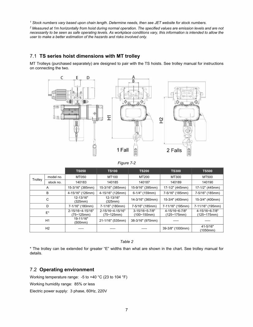
17.0 Allowable limits
17.1 Hook wear limits (top and bottom)
Normal hook measurements are shown in the chart below. Replace the hook if it exceeds the given measurements. Never heat-treat the hook or attach anything to the hook by welding.
NOTE: Excessive hook throat opening or twist indicates abuse or overloading of the hoist. If such deformation is discovered, inspect the hoist, chain and all supporting members very carefully for additional indications of excessive hoist loading.
Figure 16-1: top hook Figure 16-2: bottom hook
Model Capacity Hook Dimensions (mm) Allowed Stress
( kg/mm2) H1 B1 B2 H2 B3 B4 C g E
TS050 1100 lbs. (500kg)
T 33 22 10 29 22 10 40 25.5 55 70
B 28 18 8 23 18 8 35 26 50 70
TS100 2200 lbs. (1000kg)
T 38 28 12 33 28 12 46 31 65 100
B 33 23 9 29 23 9 40 28 61 70
TS-200 4400 lbs. (2000kg)
T ; B 55 34 19 48 34 19 52 40 90 70
TS-300 6600 lbs. (3000kg)
T ; B 55 34 19 48 34 19 52 40 90 70
TS-500 11000 lbs. (5000kg)
T ; B 66 44 23 60 44 23 62 45 100 70
Table 5
T = top hook; B = bottom hook

19
17.2 Chain wear limits
Carefully inspect the entire load chain each month. Measure each link with the provided chain gauge. See Figures 16-4 and 16-5. Any load chain that shows noticeable deformation or heat influence must be replaced with a new one. Never extend load chain by welding a second piece to the original.
The load sheave and chain regulator must also be inspected, as any wear or damage to the chain will be transmitted to these parts also.
Any replacement of chain and sheave elements must be done by qualified persons only.
OK NO
OK
OK NO
Figure 16-4: pitch Figure 16-5: diameter
Model Diameter
(mm) (d)
Inside Length (mm)
(p)
Inside Width (mm) (b1)
Outside Width (mm) (b2)
Breaking Load (kN)
TS050 Ø6.3 19.1 7.9 21.4 50
TS100 Ø7.1 20.2 8.1 23.2 63.3
TS200 TS200
Ø10.0 30.2 12.5 33.2 128
TS500 Ø11.2 34 14 37.5 160
Table 6

20
18.0 Chain container selection for TS series hoist Table 7
Hoist tonnage
Model
Lift (feet)
10 15 20 30 40 50 60 70 80 90 100
1/2T TS050 -01 -01 -01 -04 -04 -05 -05 -05 -07 -07 -07
1T TS100 -02 -02 -02 -03 -03 -06 -06 -06 -08 -08 -08
2T TS200 -09 -09 -09 -09 -09 -09 -11 -11 -11 -11 -11
3T TS300 -10 -10 -10 -10 -10 -12 -12 -12 -12 -12
5T TS500 -10 -10 -10 -10 -12 -12 -12 -12 -12
Container part numbers: TS-CC-01 (plastic) TS-CC-02 (plastic) TS-CC-03 (plastic) TS-CC-04 (plastic) TS-CC-05 (steel) TS-CC-06 (steel) TS-CC-07 (steel) TS-CC-08 (steel) TS-CC-09 (canvas) TS-CC-10 (canvas) TS-CC-11 (steel) TS-CC-12 (steel)
19.0 Pendant controllers for TS hoists Table 8
Part no. Description
104055 WIRED PENDANT, 2-BTN, TS, for 10FT Hoist 104056 WIRED PENDANT, 2-BTN, TS, for 15FT Hoist 104057 WIRED PENDANT, 2-BTN, TS, for 20FT Hoist 104196 WIRED PENDANT, 4-BTN, TS+MT, for 10FT Hoist 104197 WIRED PENDANT, 4-BTN, TS+MT, for 15FT Hoist 104198 WIRED PENDANT, 4-BTN, TS+MT, for 20FT Hoist

21
20.0 Troubleshooting TS series Hoist Table 9
Important: Any servicing performed on the brake or other electrical components must be done by qualified persons only.
Trouble Probable Cause Suggested Remedy
Hoist will not respond to controls. Limit switch is tripped.
Move hook in opposite direction. If limit switches need adjustment, have qualified person inspect them.
Hoist overloaded. Reduce load to within rated capacity.
No incoming power, or low voltage. Check hoist connections to power source. If low voltage, have certified electrician check incoming power.
Fuse blown or circuit breaker tripped. Replace fuse/re-set circuit breaker. Broken wire to control pendant. Locate and repair. Incorrect phasing. Switch any two of the three supply wires. Brake won’t release; or rectifier damaged in the phase protector.
Inspect continuity in brake; replace phase protector.
Control contacts not opening/closing properly.
Check electrical continuity; replace any defective parts.
Faulty contactor.
Operate hoist manually; if successful, then control circuit is faulty – locate and repair. If hoist still does not run check main supply. If input supply is correct but output supply is faulty, replace contactor.
Motor malfunction. Have motor inspected by a qualified service technician; repair or replace as needed.
Hoist operates only intermittently.
Loose connectors; poor contacts; arcing. Inspect all wiring and contacts.
Broken conductor in control cord Test continuity of each conductor. Replace cable if needed.
Hoist refuses to stop. Welded contacts in contactor. Replace contactor.
Hoist lifts but will not lower.
Broken conductor in control cord. Test continuity of each conductor. Replace cable if needed.
Up/down switch malfunctioning. Repair or replace switch.
Hoist lowers but will not lift.
Hoist overloaded. Reduce load to within rated capacity. Up/down switch malfunction. Repair or replace switch.
Load continues drifting down excessively when hoist is stopped.
Hoist overloaded. Reduce load to within rated capacity.
Brake out of adjustment. Adjust brake air gap. Replace brake lining if worn.
Grease or oil on the lining. Open hoist, disassemble brake and clean the lining (qualified persons only).
Brake springs are damaged. Replace brake springs. Hoist moves in wrong direction.
Incorrect phasing (230V model). Switch any two of the three supply wires
Motor overheats.
Excessive load or too frequent use; or affected by ambient temperature
Operate within rated load and according to duty cycle rating. Limit use of hoist in ambient temperatures over 104°.
Poor engagement of chain with sprocket/sheave.
Load chain is considerably worn. Replace load chain. Sprocket wheel, sheave or chain guide is considerably worn.
Replace parts as needed.
Limit switch failure.
Bad connection of limit switch leads. Inspect contacts of leads and limit switches.
Limit switch damaged. Replace.
Abnormal sounds. Brake out of adjustment. Inspect and adjust/repair as needed. Dry chain or worn sprocket Lubricate or replace as needed.
22
21.0 Replacement Parts Replacement parts are listed on the following pages. To order parts or reach our service department, call 1-800-274-6848 Monday through Friday, 8:00 a.m. to 5:00 p.m. CST. Having the Model Number and Serial Number of your machine available when you call will allow us to serve you quickly and accurately.
Non-proprietary parts, such as fasteners, can be found at local hardware stores, or may be ordered from JET.
Some parts are shown for reference only, and may not be available individually.
NOTE: If an item shows two part numbers, the hoist model on which it is used can be identified by the part number.
23
21.1.1 TS050,TS100 Motor Assembly and Housing – Exploded View

24
21.1.2 TS050,TS100 Motor Assembly and Housing – Parts List
Index No. Part No. Description Size Qty
1 ................ TS-1502101 .............. Socket Hd Cap Screw ............................................ M5×0.8×45 .................... 6 .................. TS-2143141 .............. ................................................................................. M6×1.0×75 .................... 6 2 ................ TS-2361051 .............. Spring Washer ........................................................ M5 ................................. 6 .................. TS-2361061 .............. ................................................................................. M6 ................................. 6 3 ................ TS050-A03 ................ End Cover ................................................................ ...................................... 1 .................. TS100-A03 ................ ................................................................................. ...................................... 1 4 ................ TS050-A04 ................ Motor Rotor .............................................................. ...................................... 1 .................. TS100-A04 ................ ................................................................................. ...................................... 1 5 ................ BB-62042RS ............. Bearing ................................................................... 62042RS ....................... 1 .................. BB-6205ZZ ................ ................................................................................. 6205ZZ ......................... 1 6 ................ TS050-A06 ................ Wave Washer ......................................................... 6205 .............................. 1 7 ................ TS050-A07 ................ Oil Seal ................................................................... Ø20×Ø35×8t ................. 1 .................. TS100-A07 ................ ................................................................................. Ø25×Ø45×8t ................. 1 8 ................ 6293356 .................... Key, Dbl Rd Hd ....................................................... t6×6×20L ....................... 1 9 ................ BB-62042RS ............. Bearing ................................................................... 62042RS ....................... 1 .................. BB-6304ZZ ................ ................................................................................. 6304ZZ ......................... 1 10 .............. TS050-A07 ................ Oil Seal ................................................................... Ø20×Ø35×8t ................. 1 11 .............. TS050-A11 ................ Motor End Cover ..................................................... ...................................... 1 .................. TS100-A11 ................ ................................................................................. ...................................... 1 12 .............. TS-2361051 .............. Spring Washer ........................................................ M5 ................................. 4 .................. TS-2361061 .............. ................................................................................. M6 ................................. 4 13 .............. TS-1502051 .............. Socket Hd Cap Screw ............................................. M5×0.8×20 .................... 4 .................. TS-1503061 .............. ................................................................................. M6×1.0×25 .................... 4 14 .............. 1017067 .................... C-Retaining Ring, Ext ............................................. S-19 .............................. 2 15 .............. TS050-A15 ................ Brake Assembly ...................................................... SNT-102-075 ................ 1 .................. TS100-A15 ................ ................................................................................. TSB-124-150 ................ 1 16 .............. TS-2361061 .............. Spring Washer ........................................................ M6 ................................. 3 17 .............. TS-1503081 .............. Socket Hd Cap Screw ............................................. M6×1.0×35 .................... 3 18 .............. TS050-A18 ................ Oil Seal ................................................................... VA18 ............................. 1 19 .............. TS050-A19 ................ Brake End Cover Gasket ......................................... ...................................... 1 .................. TS100-A19 ................ ................................................................................. ...................................... 1 20 .............. TS050-A20 ................ Brake End Cover ..................................................... ...................................... 1 .................. TS100-A20 ................ ................................................................................. ...................................... 1 21 .............. TS-2361051 .............. Spring Washer ........................................................ M5 ................................. 4 22 .............. TS-1502021 .............. Socket Hd Cap Screw ............................................. M5×0.8×10 .................... 4 23 .............. TS050-A23 ................ Pin .......................................................................... Ø3×10 ........................... 2 24 .............. TS050-A24 ................ Fan ......................................................................... Ø124×Ø14 .................... 1 .................. TS100-A24 ................ ................................................................................. Ø138×Ø16 .................... 1 25 .............. F006042 .................... C-Retaining Ring, Ext. ............................................. S-14 .............................. 1 .................. F006044 .................... ................................................................................. S-16 .............................. 1 26 .............. TS050-A26 ................ End Cover Gasket ................................................... ...................................... 1 .................. TS100-A26 ................ ................................................................................. ...................................... 1 27 .............. TS050-A27 ................ Motor Stator Assembly…………………….3~230V,60Hz,1.1/0.28kW ............ 1 .................. TS100-A27 ................ ……………………………………………….3~230V,60Hz,1.5/0.37kW ............. 1 .................. TS050-A27M ............. Motor Stator Assembly…………………….3~460V,60Hz,1.1/0.28kW ............ 1 .................. TS100-A27M ............. ……………………………………………….3~460V,60Hz,1.5/0.37kW ............. 1 28 .............. TS-2361081 .............. Spring Washer ........................................................ M8 ................................. 6 29 .............. TS-1504071 .............. Hex. Bolt ................................................................. M8×1.25×35 .................. 6 .................. TS-1504061 .............. ................................................................................. M8×1.25×30 .................. 6 30 .............. TS050-A30 ................ Pin .......................................................................... Ø5×12 ........................... 2 31 .............. TS050-A31 ................ Motor Gasket ........................................................... ...................................... 1 .................. TS100-A31 ................ ................................................................................. ...................................... 1 32 .............. TS050-A32 ................ Gearbox ................................................................... ...................................... 1 .................. TS100-A32 ................ ................................................................................. ...................................... 1 33 .............. TS050-A33 ................ Gearbox Gasket ...................................................... ...................................... 1 .................. TS100-A33 ................ ................................................................................. ...................................... 1 34 .............. TS050-A30 ................ Pin .......................................................................... Ø5×12 ........................... 2 35 .............. TS050-A35 ................ Gearbox Cover ........................................................ ...................................... 1 .................. TS100-A35 ................ ................................................................................. ...................................... 1

25
Index No. Part No. Description Size Qty
36 .............. TS-2361061 .............. Spring Washer ........................................................ M6 ................................. 6 37 .............. TS-1503121 .............. Socket Hd Cap Screw ............................................. M6×1.0×55 .................... 6 .................. TS-2236801 .............. ................................................................................. M6×1.0×85 .................... 8 38 .............. TS050-A38 ................ Electric Cover Gasket .............................................. ...................................... 1 .................. TS100-A38 ................ ................................................................................. ...................................... 1 39 .............. TS050-A39 ................ Electric Cover .......................................................... ...................................... 1 .................. TS100-A39 ................ ................................................................................. ...................................... 1 40 .............. TS-2361061 .............. Spring Washer ........................................................ M6 ................................. 8 41 .............. TS-1503091 .............. Socket Hd Cap Screw ............................................. M6×1.0×40 .................... 8 .................. TS-1503081 .............. ................................................................................. M6×1.0×35 .................... 6

26
21.2.1 TS050, TS100 Hook Assembly – Exploded View

27
21.2.2 TS050, TS100 Hook Assembly – Parts List
Index No. Part No. Description Size Qty
1 ................ TS050-B01 ................ Lock Bolt ................................................................. Ø14×83 ......................... 2 2 ................ TS050-B02 ................ Top Hook Assembly................................................. ...................................... 1 .................. TS100-B02 ................ ................................................................................. ...................................... 1 3 ................ TS050-B03 ................ Safety Latch Assembly ............................................ ...................................... 1 4 ................ TS-2361121 .............. Spring Washer ........................................................ M12 ............................... 2 5 ................ TS-1540081 .............. Hex Nut ................................................................... M12×1.75 ...................... 2 6 ................ TS050-B06 ................ Cotter Pin ................................................................ Ø3×30 ........................... 2 7 ................ TS-1541031 .............. Nylon Nut ................................................................ M8×1.25 ........................ 2 .................. TS-1541021 .............. ................................................................................ M6×1.0 .......................... 2 8 ................ TS050-B08 ................ Safety Latch Assembly ............................................ ...................................... 1 .................. TS100-B08 ................ ................................................................................. ...................................... 1 9 ................ TS050-B09 ................ Bottom Hook Assembly ........................................... ...................................... 1 .................. TS100-B09 ................ ................................................................................. ...................................... 1 10 .............. TS-1504061 .............. Socket Hd Cap Screw ............................................ M8×1.25×30 .................. 2 11 .............. TS050-B11 ................ Bottom Block Cover ................................................. ...................................... 1 .................. TS100-B11 ................ ................................................................................. ...................................... 1 12 .............. TS050-B12 ................ End Spacer .............................................................. ...................................... 1 13 .............. TS050-B13 ................ Half Spacer .............................................................. ...................................... 2 14 .............. BB-2904 .................... Thrust Bearing ........................................................ 2904 .............................. 1 15 .............. TS050-B15 ................ Bottom Hook Complete Assembly ........................... ...................................... 1 .................. TS100-B15 ................ ................................................................................. ...................................... 1

28
21.3.1 TS050, TS100 Load Chain – Exploded View

29
21.3.2 TS050, TS100 Load Chain – Parts List
Index No. Part No. Description Size Qty
1 ................ TS-1541011 .............. Nylon Nut ................................................................ M5 ................................. 2 .................. TS-1541021 .............. ................................................................................. M6 ................................. 2 2 ................ .................................. Chain Container (see chart)..................................... ...................................... 1 3 ................ TS-2235801 .............. Socket Hd Cap Screw ............................................ M5×0.8×80 .................... 2 .................. TS-2236801 .............. ................................................................................. M6×1.0×80 .................... 2 4 ................ TS050-C04 ................ Chain Regulator ....................................................... ...................................... 1 .................. TS100-C04 ................ ................................................................................. ...................................... 1 5 ................ TS-2361061 .............. Spring Washer ........................................................ M6 ................................. 4 6 ................ TS-1503041 .............. Socket Hd Cap Screw ............................................. M6x1.0x16 .................... 4 7 ................ BB-6303ZZ ................ Bearing ................................................................... 6306ZZ ......................... 1 8 ................ TS050-C08 ................ Guide Tube Ass’y .................................................... ...................................... 1 .................. TS100-C08 ................ ................................................................................. ...................................... 1 9 ................ TS050-C09 ................ Spring ...................................................................... ...................................... 2 .................. TS100-C09 ................ ................................................................................. ...................................... 2 10 .............. TS050-C10 ................ Chain Puller ............................................................. Ø6.3×19.1mm ............... 1 .................. TS100-C10 ................ ................................................................................. Ø7.1×20.2mm ............... 1 11 .............. LCHAIN-6X19 ........... Load Chain ............................................................. Ø6.3×19.1mm ........ per ft. .................. LCHAIN-7X20 ........... ................................................................................. Ø7.1×20.2mm ........ per ft. 12 .............. TS050-C12 ................ Limit Stopper Ass’y .................................................. ...................................... 2 13 .............. TS050-C13 ................ Spring ...................................................................... ...................................... 2 14 .............. TS050-C14 ................ Chain Stopper .......................................................... ...................................... 2 15 .............. TS-2361061 .............. Spring Washer ........................................................ M6 ................................. 2 16 .............. TS-1503051 .............. Socket Hd Cap Screw ............................................. M6×1.0×20 .................... 2 17 .............. TS050-C17 ................ Chain Connecting Pin ............................................. Ø14×50 ......................... 1 .................. TS100-C17 ................ ................................................................................. Ø16×80 ......................... 1 18 .............. TS050-C18 ................ Fixed Block .............................................................. ...................................... 1 .................. TS100-C18 ................ ................................................................................. ...................................... 1 19 .............. TS-2361051 .............. Spring Washer ........................................................ M5 ................................. 1 .................. TS-2361061 .............. ................................................................................. M6 ................................. 1 20 .............. TS-1502051 .............. Socket Hd Cap Screw ............................................. M5×0.8×20 .................... 1 .................. TS-1503041 .............. ................................................................................. M6×1.0×16 .................... 1
30
21.4.1 TS050, TS100 Gear Box – Exploded View

31
21.4.2 TS050, TS100 Gear Box – Parts List
Index No. Part No. Description Size Qty
1 ................ BB-6002ZZ ................ Bearing ................................................................... 6002ZZ ......................... 1 .................. BB-6202 .................... Bearing ................................................................... 6202 .............................. 1 2 ................ TS050-D02 ................ 2nd Gear ................................................................. M1.25×50T×14L ........... 1 .................. TS100-D02 ................ 2nd Gear ................................................................. M1.5×42T×17L ............. 1 3 ................ TS050-D03 ................ 3rd Gear ................................................................. M2×12T×88L ................ 1 .................. TS100-D03 ................ 3rd Gear ................................................................. M2×10T×105L .............. 1 4 ................ 5512400 .................... Key, Dbl Rd Hd ........................................................ t6×6×12L ....................... 1 .................. 3K00227 .................... Key, Dbl Rd Hd ....................................................... t6×6×15L ....................... 1 5 ................ BB-6002ZZ ................ Bearing ................................................................... 6002ZZ ......................... 1 .................. BB-6202 .................... Bearing ................................................................... 6202 .............................. 1 6 ................ BB-6204 .................... Bearing ................................................................... 6204 .............................. 1 .................. BB-6304 .................... Bearing ................................................................... 6304 .............................. 1 7 ................ TS050-D07A ............. 5th Gear Ass’y ........................................................ M2×12T ......................... 1 .................. .................................. 5th Gear Ass’y ........................................................ M2×13T ......................... 1 .................. TS100-D07A ............. 5th Gear Ass’y ........................................................ M2.25×13T .................... 1 .................. .................................. 5th Gear Ass’y ........................................................ M2.25×15T .................... 1 8 ................ TS050-D08 ................ Load Brake Gear Spacer ......................................... ...................................... 2 .................. TS100-D08 ................ ................................................................................. ...................................... 2 9 ................ TS050-D09 ................ Breather Plug ........................................................... ...................................... 1 10 .............. TS050-D10 ................ Hex. Oil Plug ............................................................ ...................................... 1 11 .............. TS050-D11 ................ Ratchet Ass’y ........................................................... ...................................... 1 .................. TS100-D11 ................ ................................................................................. ...................................... 1 12 .............. TS050-D12 ................ Brake Bushing ......................................................... ...................................... 1 .................. TS100-D12 ................ ................................................................................. ...................................... 1 13 .............. SB-6MM .................... Ball .......................................................................... Ø6 ................................. 3 14 .............. TS050-D14 ................ 4th Gear Ass’y ........................................................ M2×49T×18 .................. 1 .................. TS100-D14 ................ 4th Gear Ass’y ........................................................ M2×54T×21 .................. 1 15 .............. TS050-D15 ................ Brake Body ............................................................. Ø90×7.6L ...................... 1 .................. TS100-D15 ................ Brake Body ............................................................. Ø101×7L ....................... 1 16 .............. TS050-D16 ................ Disc Spring ............................................................. Ø70×ø35.5×3t ............... 3 .................. TS100-D16 ................ Disc Spring ............................................................. Ø80×ø36×3t .................. 4 17 .............. TS050-D17 ................ O-Ring .................................................................... P-29 .............................. 1 18 .............. TS050-D18 ................ O-Ring .................................................................... P-14 .............................. 1 .................. TS100-D18 ................ O-Ring .................................................................... P-18 .............................. 1 19 .............. TS050-D19 ................ Disc Spring Bushing ................................................ ...................................... 1 .................. TS100-D19 ................ ................................................................................. ...................................... 1 20 .............. TS050-D20 ................ Spacer .................................................................... AW06 ............................ 1 .................. TS100-D20 ................ Spacer .................................................................... AW07 ............................ 1 21 .............. TS050-D21 ................ Nut .......................................................................... KM6 .............................. 1 .................. TS100-D21 ................ Nut .......................................................................... KM7 .............................. 1 22 .............. TS050-D22 ................ End Spacer ............................................................. Ø40×Ø14×13L .............. 1 .................. TS100-D22 ................ End Spacer ............................................................. Ø45×Ø14×13L .............. 1 23 .............. TS-2342121 .............. Lock Nut ................................................................. M12×1.75 ...................... 1 24 .............. TS050-D24 ................ Bearing ................................................................... 6910ZZ ......................... 1 .................. BB-6912 .................... Bearing ................................................................... 6912 .............................. 1 25 .............. TS050-D25 ................ Oil Seal ................................................................... Ø50×Ø68×9t ................. 1 .................. TS100-D25 ................ Oil Seal ................................................................... Ø60×Ø80×8t ................. 1 26 .............. BB-6006ZZ ................ Bearing ................................................................... 6006ZZ ......................... 1 .................. BB-6306ZZ ................ Bearing ................................................................... 6306ZZ ......................... 1 27 .............. TS050-D27 ................ Load Sheave .......................................................... Ø68.5×144L .................. 1 .................. TS100-D27 ................ Load Sheave .......................................................... Ø73×158.5L .................. 1 28 .............. TS050-D28 ................ Oil Seal ................................................................... Ø35×Ø50×8t ................. 1 .................. TS100-D28 ................ Oil Seal ................................................................... Ø45×Ø72×10t ............... 1 29 .............. BB-6006ZZ ................ Bearing ................................................................... 6006ZZ ......................... 1 .................. BB-6208 .................... Bearing ................................................................... 6208 .............................. 1 30 .............. F006050 .................... C-Retaining Ring, Ext .............................................. S-25 .............................. 1 .................. F006096 .................... C-Retaining Ring, Ext .............................................. S-38 .............................. 1 31 .............. TS050-D31 ................ 6th Gear .................................................................. M2×43T ......................... 1 .................. TS100-D31 ................ 6th Gear .................................................................. M2.25×54T .................... 1 32 .............. F006097 .................... C-Retaining Ring, Int .............................................. R-55 .............................. 1

32
Index No. Part No. Description Size Qty
.................. F006094 .................... C-Retaining Ring, Int ............................................... R-80 .............................. 1 33 .............. TS050-D33 ................ Lubricant Drain Bolt ................................................. ...................................... 1 34 .............. TS050-D34 ................ Ratchet Pawl Pin ..................................................... ...................................... 2 .................. TS100-D34 ................ ................................................................................. ...................................... 1 35 .............. TS050-D35 ................ Ratchet Pawl Spring ................................................ ...................................... 2 .................. TS100-D35 ................ ................................................................................. ...................................... 1 36 .............. TS050-D36 ................ Ratchet Pawl ........................................................... ...................................... 2 .................. TS100-D36 ................ ................................................................................. ...................................... 1 37 .............. F006098 .................... C-Retaining Ring, Ext .............................................. S-11 .............................. 2

33
This page intentionally left blank
34
21.5.1 TS050, TS100 Electrical Assembly – Exploded View

35
21.5.2 TS050, TS100 Electrical Assembly – Parts List
Index No. Part No. Description Size Qty
1 ................ TS050-E01 ................ Upper & Lower Limit Switch..................................... ...................................... 1 .................. TS100-E01 ................ ................................................................................. ...................................... 1 2 ................ TS050-E02 ................ Transformer Bracket ................................................ ...................................... 1 .................. TS100-E02 ................ ................................................................................. ...................................... 1 3 ................ TS050-E03 ................ Transformer ............................................................. PS-116 .......................... 1 .................. TS100-E03 ................ Transformer ............................................................. PS-16205N ................... 1 4 ................ TS050-E04 ................ Electric Bracket ........................................................ ...................................... 1 .................. TS100-E04 ................ ................................................................................. ...................................... 1 5 ................ TS-2361051 .............. Spring Washer ........................................................ M5 ................................. 4 6 ................ TS-1502021 .............. Socket Hd Cap Screw ............................................ M5×0.8×10L .................. 4 7 ................ TS050-E07 ................ Contactor Rail .......................................................... ...................................... 2 .................. TS100-E07 ................ ................................................................................. ...................................... 2 8 ................ TS050-E08 ................ Contactor............................................LC2-K09004-F7 110V 4A ................... 1 .................. TS100-E08 ................ ............................................................LC1D12-F7 110V 3A1a 1b ................ 1 9 ................ TS100-E08 ................ Contactor ...........................................LC1D12-F7 110V 3A1a 1b ................. 1 10 .............. TS050-E10 ................ Contactor............................................LC1-K09008-F7 110V 2A2B .............. 1 .................. TS100-E10 ................ ............................................................LC1D12-F7 110V 3A1a 1b ................ 1 11 .............. TS050-E11 ................ Contactor............................................LC1-K0901-F7 110V 3A1b ................. 1 .................. TS100-E11 ................ ............................................................LC1D128-F7 110V 2A2B ................... 1 12 .............. TS050-E12 ................ Phase Sequence Protector ..................................... RM17-TG00 .................. 1 13 .............. TS050-E13 ................ Terminal Block ........................................................ (PT 2,5-QUATTRO) ...... 4 14 .............. TS050-E14 ................ Rectifier ................................................................... KBC10 .......................... 1 15 .............. TS050-E15 ................ Varistor .................................................................... 14K471U ....................... 2 16 .............. TS050-E16 ................ Contactor Rail .......................................................... ...................................... 1 17 .............. TS050-E17 ................ Fuse Holder ............................................................. ...................................... 2 18 .............. TS050-E18 ................ Fuse ......................................................................... ...................................... 2 19 .............. TS-1540041 .............. Nut .......................................................................... M6×1.0 .......................... 1 20 .............. TS050-E20 ................ Eye Bolt .................................................................. M6×1.0 .......................... 1 21 .............. TS050-E21 ................ Cable Gland ............................................................ M25-18 .......................... 1 22 .............. TS050-E22 ................ Shackle ................................................................... 3/16" .............................. 1 23 .............. .................................. Wired Pendant Control (see chart) .......................... ...................................... 1 24 .............. TS050-E24 ................ Cable Gland ............................................................ M20-13 .......................... 1 25 .............. TS050-E25 ................ Cable Gland ............................................................ SPG-M20BM20×1.5 ...... 2 26 .............. TS050-E26 ................ Cover ....................................................................... ...................................... 1 .................. TS100-E26 ................ ................................................................................. ...................................... 1 27 .............. TS-2361041 .............. Spring Washer ........................................................ M4 ................................. 2 28 .............. TS-2171012 .............. Phillips Pan Hd Mach Screw .................................. M4×0.7×6L .................... 2 29 .............. TS050-E29 ................ Power Cable ............................................................ 2.0mmx4C .................... 1

36
21.6.1 TS200,TS300,TS500 Motor Assembly and Housing – Exploded View

37
21.6.2 TS200,TS300,TS500 Motor Assembly and Housing – Parts List
Index No. Part No. Description Size Qty
1 ................ TS-2172012 .............. Phillips Pan Hd Mach Screw ................................... M5×0.8×8 ...................... 4 2 ................ TS200-A02 ................ End Cover ................................................................ ...................................... 1 3 ................ TS200-A03 ................ Motor Rotor .............................................................. ...................................... 1 4 ................ 5508937 .................... Key, Dbl Rd Hd ........................................................ t7×7×25L ....................... 1 5 ................ TS200-A05 ................ Oil Seal ................................................................... Ø45×Ø60×8t ................. 1 6 ................ TS200-A06 ................ Motor Stator Ass'y .................................................. 3~230V60Hz3.7/0.9kW . 1 7 ................ TS200-A07 ................ Bearing ................................................................... 6310ZZ ......................... 1 8 ................ TS-2311081 .............. Nut. ......................................................................... M8×1.25 ........................ 8 9 ................ TS200-A09 ................ Bearing ................................................................... 62062RU ....................... 1 10 .............. TS200-A10 ................ Oil Seal ................................................................... Ø30×Ø50×8t ................. 1 11 .............. TS200-A11 ................ Motor End Cover ..................................................... ...................................... 1 12 .............. TS-2361081 .............. Spring Washer ........................................................ M8 ................................. 4 13 .............. TS200-A13 ................ Threaded Bar .......................................................... M8×1.25×290L .............. 4 14 .............. TS200-A14 ................ Brake Ass’y TSB-165-370 ....................................... ...................................... 1 15 .............. TS-2361081 .............. Spring Washer ........................................................ M8 ................................. 3 16 .............. TS-1504121 .............. Socket Hd Cap Screw ............................................ M8×1.25×60L ................ 3 17 .............. F006049 .................... C-Retaining Ring, Ext .............................................. S-24 .............................. 1 18 .............. TS200-A18 ................ Oil Seal ................................................................... VA25 ............................. 1 19 .............. TS200-A19 ................ Brake End Cover Gasket ......................................... ...................................... 1 20 .............. TS200-A20 ................ Brake End Cover ..................................................... ...................................... 1 21 .............. TS-2361061 .............. Spring Washer ........................................................ M6 ................................. 4 22 .............. TS-1503021 .............. Socket Hd Cap Screw ............................................. M6×0.8×10L .................. 4 23 .............. TS200-A23 ................ Fan ......................................................................... Ø165×Ø19odd .............. 1 24 .............. 1017067 .................... C-Retaining Ring, Ext ............................................. S-19 .............................. 1 25 .............. TS200-A25 ................ Bearing Housing ..................................................... ...................................... 1 26 .............. TS-2361081 .............. Spring Washer ........................................................ M8 ................................. 4 27 .............. TS-1504041 .............. Socket Hd Cap Screw ............................................. M8×1.25×20L ................ 4 28 .............. TS200-A28 ................ Limit Plate ................................................................ ...................................... 1 29 .............. TS-1502021 .............. Socket Head Cap Screws ....................................... M5×0.8×10 .................... 3 30 .............. TS-2361081 .............. Spring Washer ........................................................ M8 ................................. 4 31 .............. TS-1504021 .............. Socket Hd Cap Screw ............................................. M8×1.25×12L ................ 4 32 .............. TS200-A32 ................ Limit Switch ............................................................. ...................................... 1 33 .............. TS200-A33 ................ Limit Cover Gasket .................................................. ...................................... 1 34 .............. TS200-A34 ................ Limit Cover .............................................................. ...................................... 1 35 .............. TS-2361081 .............. Spring Washer ........................................................ M8 ................................. 4 36 .............. TS-1504031 .............. Socket Hd Cap Screw ............................................. M8×1.25×16L ................ 4 37 .............. TS200-A37 ................ Gearbox ................................................................... ...................................... 1 .................. TS500-A37 ................ ................................................................................. ...................................... 1 38 .............. TS200-A38 ................ Gearbox Gasket ...................................................... ...................................... 1 39 .............. TS200-A39 ................ Parallel Pin ............................................................. Ø6×Ø15 ........................ 2 40 .............. TS200-A40 ................ Gearbox Cover ........................................................ ...................................... 1 41 .............. TS-2361081 .............. Spring Washer ........................................................ M8 ................................. 9 42 .............. TS200-A42 ................ Socket Hd Cap Screw ............................................. M8×1.25×90L ................ 9 43 .............. TS200-A43 ................ Electric Cover Gasket .............................................. ...................................... 1 44 .............. TS200-A44 ................ Electric Cover .......................................................... ...................................... 1 45 .............. TS-2361081 .............. Spring Washer ........................................................ M8 ................................. 8 46 .............. TS-1504031 .............. Socket Hd Cap Screw ............................................. M8×1.25×16L ................ 8 47 .............. TS200-A47 ................ O-Ring .................................................................... P-25 .............................. 1
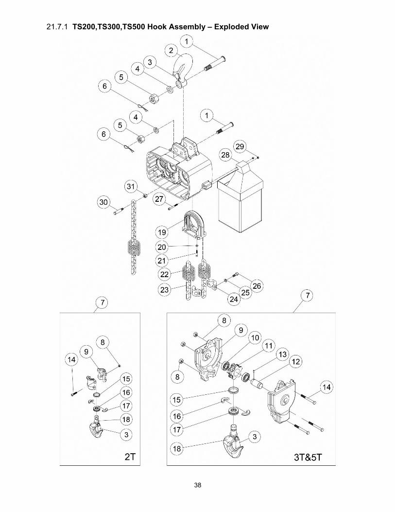
38
21.7.1 TS200,TS300,TS500 Hook Assembly – Exploded View

39
21.7.2 TS200,TS300,TS500 Hook Assembly – Parts List
Index No. Part No. Description Size Qty
1 ................ TS200-B01 ................ Top Hook Pin .......................................................... Ø25×159L ..................... 2 .................. TS500-B01 ................ ................................................................................. Ø34×159L ..................... 1 2 ................ TS200-B02 ................ Top Hook Assembly................................................. ...................................... 1 .................. TS300-B02 ................ ................................................................................. ...................................... 1 .................. TS500-B02 ................ ................................................................................. ...................................... 1 3 ................ TS200-B03 ................ Safety Latch Assembly ............................................ ...................................... 2 .................. TS300-B03 ................ ................................................................................. ...................................... 2 4 ................ TS-2361161 .............. Spring Washer ........................................................ M16 ............................... 2 .................. TS-2361201 .............. ................................................................................. M20 ............................... 1 5 ................ TS-2342161 .............. Lock Nut ................................................................. M16×1.5 ........................ 2 .................. TS500-B05 ................ ................................................................................. M20×2.0 ........................ 1 6 ................ TS200-B06 ................ Cotter Pin ................................................................ 3/32"×1"L ...................... 2 7 ................ TS200-B07 ................ Bottom Hook Complete Assembly ........................... ...................................... 1 .................. TS300-B07 ................ ................................................................................. ...................................... 1 .................. TS500-B07 ................ ................................................................................. ...................................... 1 8 ................ TS-1541031 .............. Lock Nut ................................................................. M8×1.25 ........................ 4 .................. TS-2342101 .............. ................................................................................. M10×1.5 ........................ 3 9 ................ TS200-B09 ................ Bottom Hook Housing .............................................. ...................................... 2 .................. TS300-B09 ................ ................................................................................. ...................................... 2 .................. TS500-B09 ................ ................................................................................. ...................................... 2 10 .............. BB-NK3020 ............... Needle Bearing ....................................................... TA3020Z ....................... 2 .................. TS500-B10 ................ ................................................................................. TA4025Z ....................... 2 11 .............. TS300-B11 ................ Sprocket ................................................................. Ø40×42L ....................... 1 .................. TS500-B11 ................ ................................................................................. Ø50×51L ....................... 1 12 .............. TS300-B12 ................ Bottom Hook Idle Wheel Axle ................................. Ø30×71L ....................... 1 .................. TS500-B12 ................ ................................................................................. Ø40×78L ....................... 1 13 .............. TS-209402 ................ Spring Pin ............................................................... Ø5×16L ......................... 1 14 .............. TS-1504081 .............. Socket Hd Cap Screw ............................................ M8×1.25×40L ................ 4 .................. TS-1505061 .............. ................................................................................ M10×1.5×40L ................ 3 .................. TS-1505071 .............. ................................................................................. M10×1.5×45L ................ 3 15 .............. TS200-B15 ................ Bottom Hook Retaining Ring ................................... ...................................... 1 .................. TS500-B15 ................ ................................................................................. ...................................... 1 16 .............. TS200-B16 ................ Bottom Hook Half Spacer ........................................ ...................................... 2 .................. TS500-B16 ................ ................................................................................. ...................................... 2 17 .............. BB-51106 .................. Thrust Bearing ........................................................ 51106 ............................ 1 .................. TS500-B17 ................ ................................................................................. 51207 ............................ 1 18 .............. TS200-B18 ................ Bottom Hook ............................................................ ...................................... 1 .................. TS300-B18 ................ ................................................................................. ...................................... 1 .................. TS500-B18 ................ ................................................................................. ...................................... 1 19 .............. TS200-B19 ................ Chain Regulator ....................................................... ...................................... 1 .................. TS500-B19 ................ ................................................................................. ...................................... 1 20 .............. TS-2361081 .............. Spring Washer ........................................................ M8 ................................. 4 21 .............. TS-1504041 .............. Socket Hd Cap Screw ............................................. M8×1.25×20L ................ 4 22 .............. TS200-B22 ................ Limit Spring ............................................................. ...................................... 2 .................. TS200-B22 ................ ................................................................................. ...................................... 3 .................. TS500-B22 ................ ................................................................................. ...................................... 3 23 .............. LCHAIN-10X30 ......... Load Chain ............................................................. Ø10.0x30mm ......... per ft. .................. LCHAIN-10X30 ......... ................................................................................. Ø10.0x30mm ......... per ft. .................. LCHAIN-11X34 ......... ................................................................................. Ø11.2x34mm ......... per ft. 24 .............. TS200-B24 ................ Chain Stopper ......................................................... Ø10 ............................... 2 .................. TS500-B24 ................ ................................................................................. Ø11.2 ............................ 2 25 .............. TS-2361081 .............. Spring Washer ........................................................ M8 ................................. 2 26 .............. TS-1504061 .............. Socket Hd Cap Screw ............................................. M8×1.25×30L ................ 2 27 .............. TS200-B27 ................ ................................................................................. M8×1.25×80L ................ 2 28 .............. .................................. Chain Container (see chart)..................................... ...................................... 1 29 .............. TS-1541031 .............. Nylon Nut ................................................................ M8×1.25 ........................ 2 30 .............. TS300-B30 ................ Chain Connecting Pin .............................................. Ø19×86L ....................... 1 .................. TS500-B30 ................ ................................................................................. Ø19×86L ....................... 1 31 .............. TS-2342121 .............. Nylon Nut ................................................................ M12×1.75 ...................... 1

40
21.8.1 TS200,TS300,TS500 Gear Box – Exploded View

41
21.8.2 TS200,TS300,TS500 Gear Box – Parts List
Index No. Part No. Description Size Qty
1 ................ BB-6307ZZ ................ Bearing ................................................................... 6307ZZ ......................... 1 2 ................ TS200-C02 ................ 5th Gear .................................................................. M3×15T×149.5L ........... 1 3 ................ TS200-C03 ................ Key, Dbl Rd Hd ....................................................... t12×8×30L ..................... 1 4 ................ TS200-C04 ................ 4th Gear .................................................................. M2×73T×32L ................ 1 .................. TS300-C04 ................ 4th Gear ................................................................... M2×68T×32L ................ 1 .................. TS500-C04 ................ 4th Gear ................................................................... M2×77T×32L ................ 1 5 ................ TS200-C05 ................ Bearing ................................................................... NF306 ........................... 1 6 ................ BB-6304 .................... Bearing ................................................................... 6304 .............................. 1 7 ................ TS200-C07 ................ 3rd Gear Assembly .................................................. M2×19T×210 ................ 1 .................. TS300-C07 ................ 3rd Gear Assembly .................................................. M2×24T×210 ................ 1 .................. TS500-C07 ................ 3rd Gear Assembly .................................................. M2×15T×210 ................ 1 8 ................ TS200-C08 ................ Load Brake Gear Spacer ......................................... ...................................... 2 9 ................ TS200-C09 ................ Air Plug .................................................................... ...................................... 1 10 .............. TS200-C10 ................ Hex. Oil Plug ............................................................ ...................................... 1 11 .............. TS200-C11 ................ Ratchet Ass’y ........................................................... ...................................... 1 12 .............. TS200-C12 ................ Brake Bushing ......................................................... ...................................... 1 13 .............. SB-8MM .................... Steel Ball ................................................................ Ø8 ................................. 3 14 .............. TS200-C14 ................ 2nd Gear Assembly ................................................ M1.75×68T×24 ............. 1 15 .............. TS200-C15 ................ Brake Body ............................................................. Ø112×8 ......................... 1 16 .............. TS200-C16 ................ Disc Spring ............................................................. Ø90×Ø45×3.5t .............. 4 17 .............. TS200-C17 ................ O-Ring .................................................................... P-38 .............................. 1 18 .............. TS200-C18 ................ O-Ring .................................................................... P-18 .............................. 1 19 .............. TS200-C19 ................ Disc Spring Bushing ................................................ ...................................... 1 20 .............. TS200-C20 ................ Spacer .................................................................... AW07 ............................ 1 21 .............. TS200-C21 ................ Nut .......................................................................... KM7 .............................. 1 22 .............. TS200-C22 ................ End Spacer ............................................................. Ø45×Ø14×13L .............. 1 23 .............. TS-2342121 .............. Lock Nut ................................................................. M12×1.75 ...................... 1 24 .............. BB-6912 .................... Bearing ................................................................... 6912 .............................. 1 25 .............. TS200-C25 ................ Oil Seal ................................................................... Ø60×Ø78×7t ................. 2 26 .............. TS200-A05 ................ Oil Seal ................................................................... Ø45×Ø60×8t ................. 1 27 .............. BB-6009ZZ ................ Bearing ................................................................... 6009ZZ ......................... 1 28 .............. TS200-C28 ................ Load Sheave ........................................................... ...................................... 1 .................. TS500-C28 ................ ................................................................................. ...................................... 1 29 .............. TS200-C29 ................ Load Sheave B ....................................................... Ø70×288.5L .................. 1 30 .............. TS200-C30 ................ Spacer .................................................................... Ø70×Ø50×12L .............. 1 31 .............. TS200-C31 ................ 6th Gear .................................................................. M3×64T ......................... 1 32 .............. F006071 .................... C-Retaining Ring, Ext .............................................. S-50 .............................. 1 33 .............. TS200-C33 ................ Bearing ................................................................... 6309ZZ ......................... 1 34 .............. TS200-C34 ................ 1st Gear .................................................................. M1.75×12 ...................... 1 35 .............. BB-6203ZZ ................ Bearing ................................................................... 6203ZZ ......................... 1 36 .............. TS200-C36 ................ Lubricant Drain Bolt ................................................. ...................................... 1 37 .............. TS200-C37 ................ Ratchet Pawl Pin ..................................................... ...................................... 1 38 .............. TS200-C38 ................ Ratchet Pawl Spring ................................................ ...................................... 1 39 .............. TS200-C39 ................ Ratchet Pawl ........................................................... ...................................... 1 40 .............. F006044 .................... C-Retaining Ring, Ext .............................................. S-16 .............................. 1 41 .............. TS200-C41 ................ Bearing ................................................................... 6212ZZ ......................... 1
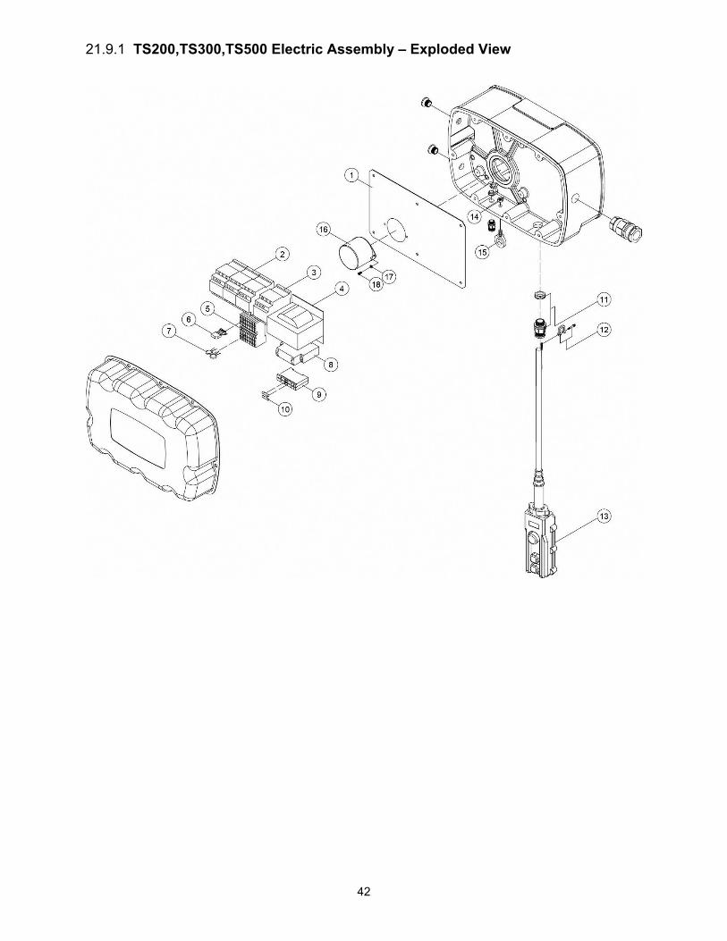
42
21.9.1 TS200,TS300,TS500 Electric Assembly – Exploded View
43
21.9.2 TS200,TS300,TS500 Electric Assembly – Parts List
Index No. Part No. Description Size Qty
1 ................ TS200-D01 ................ Electric Bracket ........................................................ ...................................... 1 2 ................ TS200-D02 ................ Contactor…………………………………….110V 3A1a1bLC1-D25-F7 ........... 3 3 ................ TS200-D03 ................ Contactor…………………………………….110V 2A2BLC1-D258-F7 ............. 1 4 ................ TS200-D04 ................ Transformer ............................................................ PS-16213N ................... 1 5 ................ TS200-D05 ................ Terminal Block ........................................................ PT 2,5-QUATTRO ...... 12 6 ................ TS200-D06 ................ Rectifier ................................................................... KBC10 .......................... 1 7 ................ TS200-D07 ................ Varistor ................................................................... 14K471U ....................... 2 8 ................ TS200-D08 ................ Phase Sequence Protector ...................................... RM17-TG00 .................. 1 9 ................ TS200-D09 ................ Fuse Holder ............................................................. ...................................... 2 10 .............. TS200-D10 ................ Fuse ......................................................................... ...................................... 2 11 .............. TS200-D11 ................ Cable Gland ............................................................. M25-18 .......................... 1 12 .............. TS200-D12 ................ Shackle .................................................................... 3/16" .............................. 1 13 .............. .................................. Wired Pendant Control (see chart) .......................... ...................................... 1 14 .............. TS-2311081 .............. Nut ........................................................................... M8×1.25 ........................ 1 15 .............. TS200-D15 ................ Eye Bolt ................................................................... M8×1.25 ........................ 1 16 .............. TS200-D16 ................ Cover ....................................................................... ...................................... 1 17 .............. TS-2361041 .............. Spring Washer ......................................................... M4 ................................. 2 18 .............. TS-2171012 .............. Phillips Pan Hd Mach Screw ................................... M4×0.7×6L .................... 2 19 .............. TS200-D19 ................ Power Cable ............................................................ 3.5mmx4C .................... 1
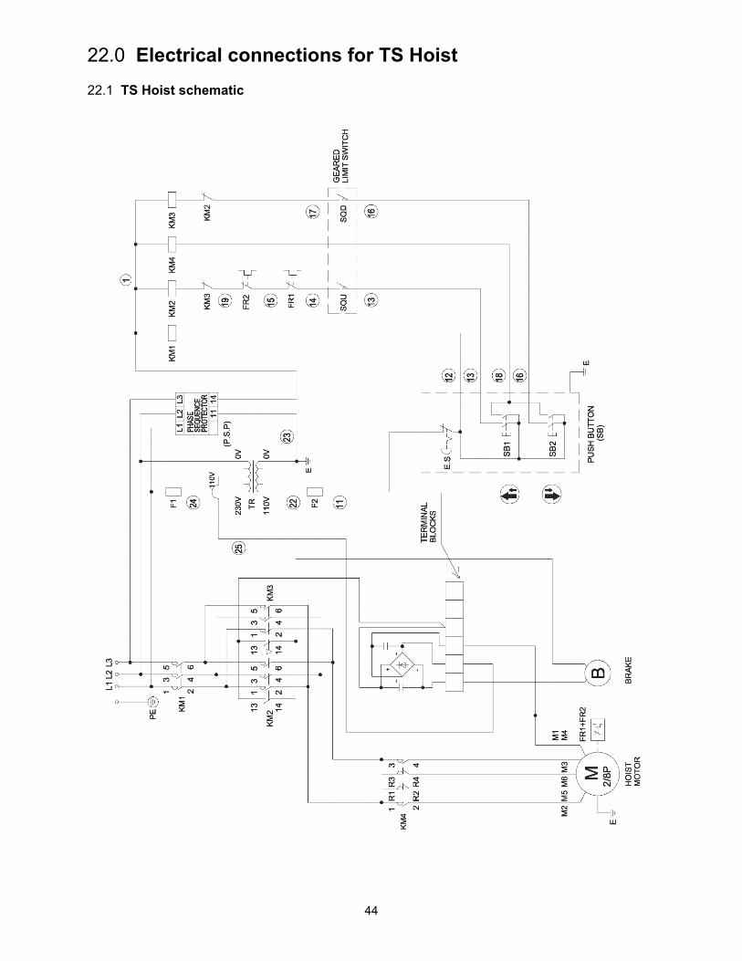
44
22.0 Electrical connections for TS Hoist 22.1 TS Hoist schematic
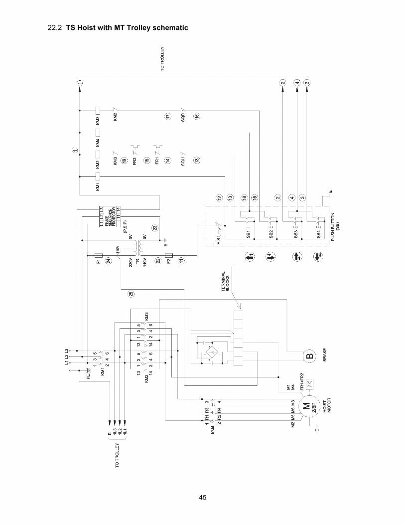
45
22.2 TS Hoist with MT Trolley schematic

46
23.0 Warranty and Service JET warrants every product it sells against manufacturers’ defects. If one of our tools needs service or repair, please contact Technical Service by calling 1-800-274-6846, 8AM to 5PM CST, Monday through Friday.
Warranty Period The general warranty lasts for the time period specified in the literature included with your product or on the official JET branded website.
JET products carry a limited warranty which varies in duration based upon the product. (See chart below) Accessories carry a limited warranty of one year from the date of receipt. Consumable items are defined as expendable parts or accessories expected to become inoperable within a
reasonable amount of use and are covered by a 90 day limited warranty against manufacturer’s defects.
Who is Covered This warranty covers only the initial purchaser of the product from the date of delivery.
What is Covered This warranty covers any defects in workmanship or materials subject to the limitations stated below. This warranty does not cover failures due directly or indirectly to misuse, abuse, negligence or accidents, normal wear-and-tear, improper repair, alterations or lack of maintenance. JET woodworking machinery is designed to be used with Wood. Use of these machines in the processing of metal, plastics, or other materials outside recommended guidelines may void the warranty. The exceptions are acrylics and other natural items that are made specifically for wood turning.
Warranty Limitations Woodworking products with a Five Year Warranty that are used for commercial or industrial purposes default to a Two Year Warranty. Please contact Technical Service at 1-800-274-6846 for further clarification.
How to Get Technical Support Please contact Technical Service by calling 1-800-274-6846. Please note that you will be asked to provide proof of initial purchase when calling. If a product requires further inspection, the Technical Service representative will explain and assist with any additional action needed. JET has Authorized Service Centers located throughout the United States. For the name of an Authorized Service Center in your area call 1-800-274-6846 or use the Service Center Locator on the JET website.
More Information JET is constantly adding new products. For complete, up-to-date product information, check with your local distributor or visit the JET website.
How State Law Applies This warranty gives you specific legal rights, subject to applicable state law.
Limitations on This Warranty JET LIMITS ALL IMPLIED WARRANTIES TO THE PERIOD OF THE LIMITED WARRANTY FOR EACH PRODUCT. EXCEPT AS STATED HEREIN, ANY IMPLIED WARRANTIES OF MERCHANTABILITY AND FITNESS FOR A PARTICULAR PURPOSE ARE EXCLUDED. SOME STATES DO NOT ALLOW LIMITATIONS ON HOW LONG AN IMPLIED WARRANTY LASTS, SO THE ABOVE LIMITATION MAY NOT APPLY TO YOU. JET SHALL IN NO EVENT BE LIABLE FOR DEATH, INJURIES TO PERSONS OR PROPERTY, OR FOR INCIDENTAL, CONTINGENT, SPECIAL, OR CONSEQUENTIAL DAMAGES ARISING FROM THE USE OF OUR PRODUCTS. SOME STATES DO NOT ALLOW THE EXCLUSION OR LIMITATION OF INCIDENTAL OR CONSEQUENTIAL DAMAGES, SO THE ABOVE LIMITATION OR EXCLUSION MAY NOT APPLY TO YOU. JET sells through distributors only. The specifications listed in JET printed materials and on official JET website are given as general information and are not binding. JET reserves the right to effect at any time, without prior notice, those alterations to parts, fittings, and accessory equipment which they may deem necessary for any reason whatsoever. JET® branded products are not sold in Canada by JPW Industries, Inc.
Product Listing with Warranty Period 90 Days – Parts; Consumable items 1 Year – Motors; Machine Accessories 2 Year – Metalworking Machinery; Electric Hoists, Electric Hoist Accessories; Woodworking Machinery used for industrial or commercial purposes; Air Tools 5 Year – Woodworking Machinery Limited Lifetime – JET Parallel clamps; VOLT Series Electric Hoists; Manual Hoists; Manual Hoist Accessories; Shop Tools; Warehouse & Dock products; Hand Tools
NOTE: JET is a division of JPW Industries, Inc. References in this document to JET also apply to JPW Industries, Inc., or any of its successors in interest to the JET brand.

47

49
427 New Sanford Road LaVergne, Tennessee 37086
Phone: 800-274-6848 www.jettools.com
![TS 125 306 - V10.2.0 - Universal Mobile …13] 3GPP TS 25.308 "High Speed Downlink Packet Access (HSDPA); Overall description; Stage 2"](https://img.dokumen.tips/doc/110x75/5b4c5cf77f8b9a9a408b9c8e/ts-125-306-v1020-universal-mobile-13-3gpp-ts-25308-high-speed-downlink.jpg)