Embed Size (px)
Citation preview

Operating Instructions and Parts Manual 14” Woodworking Band Saw Model PWBS-14CS
Powermatic 427 New Sanford Rd. LaVergne, TN 37086 Part No. M-1791216 Ph.: 800-274-6848 Revision G 10/2016 www.powermatic.com Copyright © 2016 Powermatic

2
Warranty and Service Powermatic warrants every product it sells against manufacturers’ defects. If one of our tools needs service or repair, please contact Technical Service by calling 1-800-274-6846, 8AM to 5PM CST, Monday through Friday.
Warranty Period The general warranty lasts for the time period specified in the literature included with your product or on the official Powermatic branded website.
• Powermatic products carry a limited warranty which varies in duration based upon the product. (See chart below)
• Accessories carry a limited warranty of one year from the date of receipt. • Consumable items are defined as expendable parts or accessories expected to become inoperable within a
reasonable amount of use and are covered by a 90 day limited warranty against manufacturer’s defects.
Who is Covered This warranty covers only the initial purchaser of the product from the date of delivery.
What is Covered This warranty covers any defects in workmanship or materials subject to the limitations stated below. This warranty does not cover failures due directly or indirectly to misuse, abuse, negligence or accidents, normal wear-and-tear, improper repair, alterations or lack of maintenance.
Warranty Limitations Woodworking products with a Five Year Warranty that are used for commercial or industrial purposes default to a Two Year Warranty. Please contact Technical Service at 1-800-274-6846 for further clarification.
How to Get Technical Support Please contact Technical Service by calling 1-800-274-6846. Please note that you will be asked to provide proof of initial purchase when calling. If a product requires further inspection, the Technical Service representative will explain and assist with any additional action needed. Powermatic has Authorized Service Centers located throughout the United States. For the name of an Authorized Service Center in your area call 1-800-274-6846 or use the Service Center Locator on the Powermatic website.
More Information Powermatic is constantly adding new products. For complete, up-to-date product information, check with your local distributor or visit the Powermatic website.
How State Law Applies This warranty gives you specific legal rights, subject to applicable state law.
Limitations on This Warranty POWERMATIC LIMITS ALL IMPLIED WARRANTIES TO THE PERIOD OF THE LIMITED WARRANTY FOR EACH PRODUCT. EXCEPT AS STATED HEREIN, ANY IMPLIED WARRANTIES OF MERCHANTABILITY AND FITNESS FOR A PARTICULAR PURPOSE ARE EXCLUDED. SOME STATES DO NOT ALLOW LIMITATIONS ON HOW LONG AN IMPLIED WARRANTY LASTS, SO THE ABOVE LIMITATION MAY NOT APPLY TO YOU. POWERMATIC SHALL IN NO EVENT BE LIABLE FOR DEATH, INJURIES TO PERSONS OR PROPERTY, OR FOR INCIDENTAL, CONTINGENT, SPECIAL, OR CONSEQUENTIAL DAMAGES ARISING FROM THE USE OF OUR PRODUCTS. SOME STATES DO NOT ALLOW THE EXCLUSION OR LIMITATION OF INCIDENTAL OR CONSEQUENTIAL DAMAGES, SO THE ABOVE LIMITATION OR EXCLUSION MAY NOT APPLY TO YOU. Powermatic sells through distributors only. The specifications listed in Powermatic printed materials and on the official Powermatic website are given as general information and are not binding. Powermatic reserves the right to effect at any time, without prior notice, those alterations to parts, fittings, and accessory equipment which they may deem necessary for any reason whatsoever.
Product Listing with Warranty Period 90 Days – Parts; Consumable items 1 Year – Woodworking Machinery used for industrial or commercial purposes 5 Year – Woodworking Machinery
NOTE: Powermatic is a division of JPW Industries, Inc. References in this document to Powermatic also apply to JPW Industries, Inc., or any of its successors in interest to the Powermatic brand.

3
Table of Contents Warranty and Service .................................................................................................................................... 2 Table of Contents .......................................................................................................................................... 3 Warning ......................................................................................................................................................... 5 Introduction.................................................................................................................................................... 6 Features and Specifications .......................................................................................................................... 7 Grounding Instructions .................................................................................................................................. 8
115 Volt Operation ..................................................................................................................................... 8 230 Volt Operation ..................................................................................................................................... 8 Extension Cords ........................................................................................................................................ 9
Unpacking ................................................................................................................................................... 10 Contents of the Shipping Container ........................................................................................................ 10
Installation and Assembly ........................................................................................................................... 12 Mounting Band Saw to Stand .................................................................................................................. 12 Installing Drive Belt .................................................................................................................................. 13 Installing Trunnion Support ..................................................................................................................... 14 Installing Extension Table ....................................................................................................................... 14 Installing Main Table ................................................................................................................................ 14 Leveling the Extension Table .................................................................................................................. 15 Installing Rear Rail .................................................................................................................................. 15 Installing Front Rail and Rip Fence ......................................................................................................... 16 Resaw Guide ........................................................................................................................................... 18 Blower Nozzle .......................................................................................................................................... 18 Work Lamp .............................................................................................................................................. 18 Installing Quick Tension Lever ................................................................................................................ 19 Stand Attachments .................................................................................................................................. 19 Dust Collection ........................................................................................................................................ 19 Riser Block Accessory ............................................................................................................................. 19
Adjustments ................................................................................................................................................ 20 Tilting the Table ....................................................................................................................................... 20 Adjusting 90° Table Stop ......................................................................................................................... 20 Table Aligned with Blade ......................................................................................................................... 21 Installing Blades ...................................................................................................................................... 21 Blade Tension .......................................................................................................................................... 22 Blade Tracking ......................................................................................................................................... 23 Guide Post and Upper Blade Guard ........................................................................................................ 23 Upper Bearing Guides ............................................................................................................................. 24 Lower Bearing Guides ............................................................................................................................. 24 Miter Gauge ............................................................................................................................................. 25 On/Off Switch .......................................................................................................................................... 26
Maintenance ................................................................................................................................................ 26 Blade Selection ........................................................................................................................................... 27
Width........................................................................................................................................................ 27 Pitch ......................................................................................................................................................... 27 Shape ...................................................................................................................................................... 27 Set ........................................................................................................................................................... 28 Material .................................................................................................................................................... 28 Blade Breakage ....................................................................................................................................... 28
Operation..................................................................................................................................................... 29 General Procedure .................................................................................................................................. 29 Ripping .................................................................................................................................................... 29 Crosscutting ............................................................................................................................................. 29 Resawing ................................................................................................................................................. 30 Blade Lead .............................................................................................................................................. 30
Troubleshooting – Mechanical and Electrical Problems ............................................................................. 31 Troubleshooting – Operating Problems ...................................................................................................... 32 Optional Accessories .................................................................................................................................. 34 Blade Selection Guide ................................................................................................................................. 35
For Radius Cutting ................................................................................................................................... 35

4
Replacement Parts ...................................................................................................................................... 36 Parts List: Body Assembly ....................................................................................................................... 36 Body Assembly ........................................................................................................................................ 39 Parts List: Closed Stand Assembly ......................................................................................................... 40 Closed Stand Assembly .......................................................................................................................... 41 Parts List: Fence and Rail Assembly ....................................................................................................... 42 Fence and Rail Assembly ........................................................................................................................ 43 Parts List: Table and Trunnion Assembly................................................................................................ 44 Parts List: Miter Gauge Assembly ........................................................................................................... 45 Parts List: Blade Tension Lever .............................................................................................................. 46
Electrical Connections for PWBS-14CS ..................................................................................................... 47

5
Warning
1. Read and understand this entire owner’s manual before attempting assembly or operation.
2. Read and understand the warnings posted on the machine and in this manual. Failure to comply with all of these warnings may cause serious injury.
3. Replace the warning labels if they become obscured or removed.
4. This band saw is designed and intended for use by properly trained and experienced personnel only. If you are not familiar with the proper and safe operation of a band saw, do not use until proper training and knowledge have been obtained.
5. Do not use this band saw for other than its intended use. If used for other purposes, Powermatic disclaims any real or implied warranty and holds itself harmless from any injury that may result from that use.
6. Always wear approved safety glasses/face shields while using this band saw. (Everyday eyeglasses only have impact resistant lenses; they are not safety glasses.)
7. Before operating the band saw, remove tie, rings, watches and other jewelry, and roll sleeves up past the elbows. Remove all loose clothing and confine long hair. Non-slip footwear or anti-skid floor strips are recommended. Do not wear gloves.
8. Wear ear protectors (plugs or muffs) during extended periods of operation.
9. Drilling, sawing, sanding or machining wood products generates wood dust and other substances known to the State of California to cause cancer. Avoid inhaling dust generated from wood products or use a dust mask or other safeguards to avoid inhaling dust generated from wood products.
10. Wood products emit chemicals known to the State of California to cause birth defects or other reproductive harm. (California Health and Safety Code Section 25249.6)
11. Do not operate this machine while tired or under the influence of drugs, alcohol or any medication.
12. Make certain the switch is in the OFF position before connecting the machine to the power supply.
13. Make certain the machine is properly grounded.
14. Make all machine adjustments or maintenance with the machine unplugged from the power source.
15. Remove adjusting keys and wrenches. Form a habit of checking to see that keys and adjusting wrenches are removed from the machine before turning it on.
16. Keep safety guards in place at all times when the machine is in use. If removed for maintenance purposes, use extreme caution and replace the guards immediately.
17. Make sure the band saw is firmly secured to the stand or a work bench before use.
18. Check damaged parts. Before further use of the machine, a guard or other part that is damaged should be carefully checked to determine that it will operate properly and perform its intended function. Check for alignment of moving parts, binding of moving parts, breakage of parts, mounting and any other conditions that may affect its operation. A guard or other part that is damaged should be properly repaired or replaced.
19. Provide for adequate space surrounding work area and non-glare, overhead lighting.
20. Keep the floor around the machine clean and free of scrap material, oil and grease.
21. Keep visitors a safe distance from the work area. Keep children away.
22. Make your workshop child proof with padlocks, master switches or by removing starter keys.
23. Make your workshop child proof with padlocks, master switches or by removing starter keys.
24. Give your work undivided attention. Looking around, carrying on a conversation and “horse-play” are careless acts that can result in serious injury.
25. Maintain a balanced stance at all times so that you do not fall or lean against the blade or other moving parts. Do not overreach or use excessive force to perform any machine operation.

6
26. Use the right tool at the correct speed and feed rate. Do not force a tool or attachment to do a job for
which it was not designed. The right tool will do the job better and safer.
27. Make relief cuts where possible, when cutting curved stock.
28. When feeding small work pieces into the blade, always use a push stick, fixture, or similar device to keep hands at a safe distance.
29. Use recommended accessories; improper accessories may be hazardous.
30. Do not expose machine to rain or use in wet or damp locations.
31. Maintain tools with care. Keep blades sharp and clean for the best and safest performance. Follow instructions for lubricating machine and changing accessories.
32. Turn off the machine and disconnect from power before cleaning. Use a brush or compressed air to remove chips or debris — do not use your hands.
33. Do not stand on the machine. Serious injury could occur if the machine tips over.
34. Never leave the machine running unattended. Turn the power off and do not leave the machine until it comes to a complete stop.
35. Remove loose items and unnecessary work pieces from the area before starting the machine.
Familiarize yourself with the following safety notices used in this manual:
This means that if precautions are not heeded, it may result in minor injury and/or possible machine damage.
This means that if precautions are not heeded, it may result in serious and possibly fatal injury.
Introduction This manual is provided by Powermatic covering the safe operation and maintenance procedures for a Powermatic Model PWBS-14CS Band Saw. This manual contains instructions on installation, safety precautions, general operating procedures, maintenance instructions and parts breakdown. This machine has been designed and constructed to provide consistent, long-term operation if used in accordance with instructions set forth in this manual. If there are any questions or comments, please contact either your local supplier or Powermatic. Powermatic can also be reached at our web site: www. powermatic.com.
The specifications in this manual were current at the time this manual was published, but because of our policy of continuous improvement, Powermatic reserves the right to change specifications at any time and without prior notice, without incurring obligations.
Register your product online -
http://www.powermatic.com/us/en/service-and-support/warranty/registration/

7
Features and Specifications
Figure 1
Model Number ............................................................................................................................ PWBS-14CS Stock Number ................................................................................................................................. 1791216K Resaw (Height) Capacity (in.) ....................................................................................................................... 6 Cutting Width (Throat Capacity)(in.) ..................................................................................................... 13-1/2 Minimum Saw Blade Width (in.) ................................................................................................................. 1/8 Maximum Saw Blade Width (in.) ................................................................................................................ 3/4 Blade Length (in.) .................................................................................................................................. 93-1/2 Main Table Size (LxW)(in.) .................................................................................................................. 15 x 15 Extension Table Size (LxW)(in.)...................................................................................................... 15 x 5-1/2 Blade Speed (SFPM) .............................................................................................................................. 3000 Table Tilt (deg.) ..................................................................................................................... 45 Right, 10 Left Table Height from Floor (in.) ....................................................................................................................... 44 Dust Chute Outside Diameter (in.) ................................................................................................................ 4 Minimum Dust Collection CFM Required .................................................................................................. 350 Motor ........................................................... TEFC, 1.5HP, 1PH, 115/230V (prewired 115V), 11/5.5A, 60Hz Recommended circuit (*subject to local electrical codes) ............................................. 30A (115V), 20A (230V) Overall Dimensions – Body and Stand fully assembled (LxWxH)(in.) ........................................ 20 x 34 x 68 Stand Footprint (LxW)(in.) ............................................................................................................. 16 x 17-1/2 Approximate Weights: Body (Net/Shipping)(lbs.) .............................................................................................................. 166/178 Closed Stand (Net/Shipping)(lbs.) .................................................................................................... 84/88

8
Grounding Instructions
This tool must be grounded while in use to protect the operator from electric shock.
In the event of a malfunction or breakdown, grounding provides a path of least resistance for electric current to reduce the risk of electric shock. This tool is equipped with an electric cord having an equipment-grounding conductor and a grounding plug. The plug must be plugged into a matching outlet that is properly installed and grounded in accordance with all local codes and ordinances.
Do not modify the plug provided. If it will not fit the outlet, have the proper outlet installed by a qualified electrician.
Improper connection of the equipment-grounding conductor can result in a risk of electric shock. The conductor, with insulation having an outer surface that is green with or without yellow stripes, is the equipment-grounding conductor. If repair or replacement of the electric cord or plug is necessary, do not connect the equipment-grounding conductor to a live terminal.
Check with a qualified electrician or service personnel if the grounding instructions are not completely understood, or if in doubt as to whether the tool is properly grounded. Use only three wire extension cords that have three-prong grounding plugs and three-pole receptacles that accept the tool’s plug.
Repair or replace a damaged or worn cord immediately.
It is recommended that the PWBS-14CS Band Saw, when operated at 115 volts, be connected to a grounded and dedicated 30 amp circuit with circuit breaker or time delay fuse. When operated at 230 volts, connect the saw to a 20 amp dedicated circuit with breaker or time delay fuse. Local codes take precedence over recommendations.
115 Volt Operation As received from the factory, your band saw is wired to run at 115 volt operation. This band saw, when wired for 115 volts, is intended for use on a circuit that has an outlet and a plug that looks like the one illustrated in Figure 2. A temporary adapter, which looks like the adapter illustrated in Figure 3, may be used to connect this plug to a two-pole receptacle, as shown in Figure 3 if a properly grounded outlet is not available. The temporary adapter should only be used until a properly grounded outlet can be installed by a qualified electrician. This adapter is not applicable in Canada. The green colored rigid ear, lug, or tab, extending from the adapter, must be connected to a permanent ground such as a properly grounded outlet box, as shown in Figure 3.
Figure 2 Figure 3
230 Volt Operation If 230V, single-phase operation is desired, the following instructions must be followed:
Disconnect the machine from the power source.
This band saw is supplied with four motor leads that are connected for 115V operation, as shown in Figure 4. Reconnect these four motor leads for 230V operation, as shown in Figure 5. These diagrams are also found inside the cover of the motor junction box.

9
The 115V attachment plug (shown in Figure 6) supplied with the band saw, must be replaced with a UL/CSA listed plug suitable for 230V operation (shown in Figure 7). Contact your local authorized Walter Meier (Manufacturing) Inc., service center or qualified electrician for proper procedures to install the plug. The band saw must comply with all local and national codes after the 230 volt plug is installed.
The band saw with a 230 volt plug should only be connected to an outlet having the same configuration (see Figure 7). No adapter is available or should be used with the 230 volt plug.
Important: In all cases (115 or 230 volts), make certain the receptacle in question is properly grounded. If you are not sure, have a registered electrician check the receptacle. NOTE: The lamp is designed for use with 115V power. If the saw is converted to 230V, discontinue use of the lamp, and use an alternate lamp with an independent electrical source.
Figure 4 Figure 5
Figure 6 Figure 7
Extension Cords If an extension cord is necessary, make sure the cord rating is suitable for the amperage listed on the machine’s motor plate. An undersized cord will cause a drop in line voltage resulting in loss of power and overheating.
Use the chart in Figure 8 as a general guide in choosing the correct size extension cord for the band saw. If in doubt, use the next heavier gauge. The smaller the gauge number, the heavier the cord.
Recommended Minimum Gauge (AWG) of Extension Cords
Ampere Rating
Volts Total Length of Cord in Feet 115 V 25 ft. 50 ft. 100 ft. 150 ft. 230 V 50 ft. 100 ft. 200 ft. 300 ft.
AWG< 6 18 16 16 14
6 to 10 18 16 14 12 10 to 12 16 16 14 12 12 to 16 14 12 Not recommended Not recommended
Figure 8

10
Unpacking The band saw is shipped in two cartons. Open both cartons and inspect contents for shipping damage. Report any damage immediately to your distributor and shipping agent. Do not discard any shipping material until the Band Saw is assembled and running properly.
Compare the contents of both cartons and all internal boxes with the following parts list to make sure all parts are intact.(*) Missing parts, if any, should be reported to your distributor. Read this instruction manual thoroughly for assembly, maintenance and safety instructions.
Contents of the Shipping Container Carton #1 – Band Saw: Refer to Figure 9. 1 Band Saw – (A) 1 guide rail – (B) 1 rip fence – (C) 1 rear rail – (D) 1 front rail – (E) 1 trunnion support – (F) 1 level board – (G) 1 miter gauge – (H) 1 main table – (J) 1 extension table – (K) 1 drive belt – (L) 1 quick tension lever – (M) 1 owner's manual (not shown) 1 warranty card (not shown) 2 Hardware packages, as follows. Hardware Package #1 contains: Refer to Figure 10. 1 support plate (HP1-A) 1 air jet nozzle (HP1-B) 1 cord clamp (HP1-C) 1 pan head screw, M5x12 (HP1-D) 2 table locking knobs (HP1-E) 6 lock washers, M8 (HP1-F) 8 flat washers, M8 (HP1-G) 5 hex nuts, M8 (HP1-H) 6 hex cap screws, M8x40 (HP1-J) 1 hex cap screw, M8x80 (HP1-K) Hardware package #2 contains: Refer to Figure 11. 3 hex (Allen) wrenches, 3,4,5mm (HP2-A) 4 spacers (HP2-B) 4 hex nuts, M8 (HP2-C) 4 socket set screws, M8x20 (HP2-D) 4 socket head cap screws, M6x25 (HP2-E) 4 lock washers, M6 (HP2-F) 4 flat washers, M6 (HP2-G) 4 socket head cap screws, M8x65 (HP2-H) 2 L-spacers (HP2-J)
Figure 9: Band Saw carton
Figure 10
Hardware package #1 (stock no. PWBS14-HP1)
Figure 11
Hardware package #2

11
Carton #2 - Stand: Refer to Figure 12. 1 Stand with motor (N) 1 pulley cover (O) 2 hardware packages, as follows. Hardware package #3 contains: Refer to Figure 13. 2 fence hooks (HP3-A) 2 miter gauge hooks (HP3-B) 1 blade hook (HP3-C) 2 pulley cover knobs (HP3-D) 4 carriage bolts, M8x16 (HP3-E) 4 flanged hex nuts, M8 (HP3-F) 2 pan head screws, M5x12 (HP3-G) 2 pan head screws, M4x10 (HP3-H) Hardware package #4 contains: Refer to Figure 14. 1 resaw pin (HP4-A) 1 resaw pin knob (HP4-B) 1 sliding pad (HP4-G) 7 hex cap screws, M6x20 (HP4-L) 7 lock washers, 1/4” (HP4-M) 7 flat washers, 1/4” (HP4-N) (*) the identifying letters/numbers in parentheses are
used throughout the text to clarify assembly. For actual part numbers if re-ordering, see the part breakdowns at the back of this manual.
(stock no. PWBS14-HP2)
Figure 12
Stand carton
Figure 13
Hardware package #3 (stock no. PWBS14-HP3)
Figure 14
Hardware package #4 (stock no. PWBS14-HPN)

12
Installation and Assembly Tools required for assembly:
open-end or box wrenches– 10mm, 12mm, 1/2” [in some cases, a socket wrench set can be used to speed assembly time]
hex (Allen) wrenches – 3, 5, 6mm Cross point (Phillips) screwdriver square straightedge
NOTE: If further clarification is needed for any of the following assembly procedures, consult the exploded views at the back of this manual.
Exposed metal surfaces on the Band Saw, such as the table, have been given a protective coating at the factory. This should be removed with a soft cloth moistened with a light solvent. Do not use gasoline, lacquer thinner, acetone, or other highly volatile solvents for this. Do not use an abrasive pad as it may scratch the polished metal surfaces.
IMPORTANT: The Band Saw must be disconnected from the power source before any assembly procedures!
Mounting Band Saw to Stand Refer to Figures 15 and 16.
1. Remove loose items from inside of stand.
2. Place stand upright on a level surface. If desired, the stand can be further stabilized by securing it to the floor with lag screws through the inside corner holes. If using a mobile base, lock the casters before assembling or operating the band saw.
The saw body is heavy – use caution when lifting, and stabilize until firmly attached to the stand. Failure to comply may cause serious injury.
3. With the aid of a second person, lift the Band Saw out of the shipping container and place on top of the stand. Make sure that front of saw (with Powermatic nameplate) faces same direction as curved stand front.
4. Line up holes in the saw base with holes in the top of the stand. Fasten saw base to the stand with four M8x40 hex cap screws (HP1-J), eight M8 flat washers (HP1-G), four M8 lock washers (HP1-F), and four M8 hex nuts (HP1-H). Use a 1/2” wrench to tighten.
Figure 15
Figure 16

13
5. Push motor cord and strain relief plate through the opening to the outside of the stand, as shown in Figure 16. Fasten the strain relief plate to the stand with two M5x12 pan head screws (HP3-G).
6. Connect the plugs of the switch cord and motor cord (Figure 16). Do not connect machine to power source during assembly.
Installing Drive Belt Refer to Figures 17 through 20.
1. The motor and wheel pulleys have been accurately aligned with each other by the manufacturer. However, the user may wish to verify this setting in case misalignment has occurred during transit. Misaligned pulleys can produce excessive wear on drive belts.
2. If the pulleys do not lie in a straight plane (Figure 17), loosen the set screw on one of the pulleys and shift the pulley in or out until both pulleys lie in a straight plane. Tighten set screw.
3. Open the lower door, and loosen the four hex nuts on the motor plate an equal amount, with a 1/2” wrench (see Figure 18). Lift up on the motor to provide slack for the drive belt installation.
4. Install the belt around the motor pulley and the wheel pulley.
5. Tension the drive belt by pushing down on the motor. You may have to push down harder on the pulley end of the motor to overcome the pressure of the drive belt and keep the motor pulley aligned with the wheel pulley.
6. Tighten the four hex nuts on the motor plate.
NOTE: The belt is properly tensioned when finger pressure between the two pulleys causes approximately 1/2” deflection (Figure 19).
7. Screw the two pulley cover knobs (HP3-D) into the threaded holes in the back of the saw, as shown in Figure 20. Slide the pulley cover down over the knobs, and tighten the knobs.
Figure 17
Figure 18
Figure 19
Figure 20

14
Installing Trunnion Support Refer to Figure 21.
1. Use the two locating pins attached to the saw body to help position the trunnion support. Attach trunnion support to saw body with two M8x30 hex cap screws (HP1-J) and two M8 lock washers (HP1-F). Tighten with a 1/2” wrench.
2. Thread M8 hex nut (HP1-H) onto the M8x80 hex cap screw (HP1-K) and install into the trunnion support as shown. Finger tighten the hex nut; this will be fully tightened later for the 90° table stop setting.
Installing Extension Table Refer to Figure 22.
1. Install a M8 hex nut (HP2-C) on each of the four M8x20 set screws (HP2-D), then install these set screws into the four outer holes of the level board (G), as shown.
2. Leave the set screws flush with the top side of the level board for now. These will be adjusted later during leveling.
3. Place four spacers (HP2-B) over the holes in the saw body, and place the level board on them, as shown. Align the four innermost holes of the level board with the spacers, and insert four M8x65 socket head cap screws (HP2-H). Firmly tighten these screws down into the base through the spacers, using a 6mm hex wrench.
4. Position the extension table (K) over the level board. Insert four M6x25 socket head cap screws (HP2-E) with four M6 lock washers (HP2-F) and four M6 flat washers (HP2-G) up through the remaining holes of the plate and into the underside of extension table. Hand tighten only at this time.
Installing Main Table Refer to Figure 23.
1. To mount the main table, remove table pin by pulling it straight out, twisting it if needed. Remove the table insert by pushing it up from beneath the table.
2. Rotate the table so that the saw blade will slide through the slot in the table. Then orient the table so the screws will slide into the holes on the trunnion support, as shown in Figure 23. Attach the two table locking knobs (HP1-E) to these screws and tighten.
3. Re-install table pin and table insert.
Figure 21
Figure 22
Figure 23
15
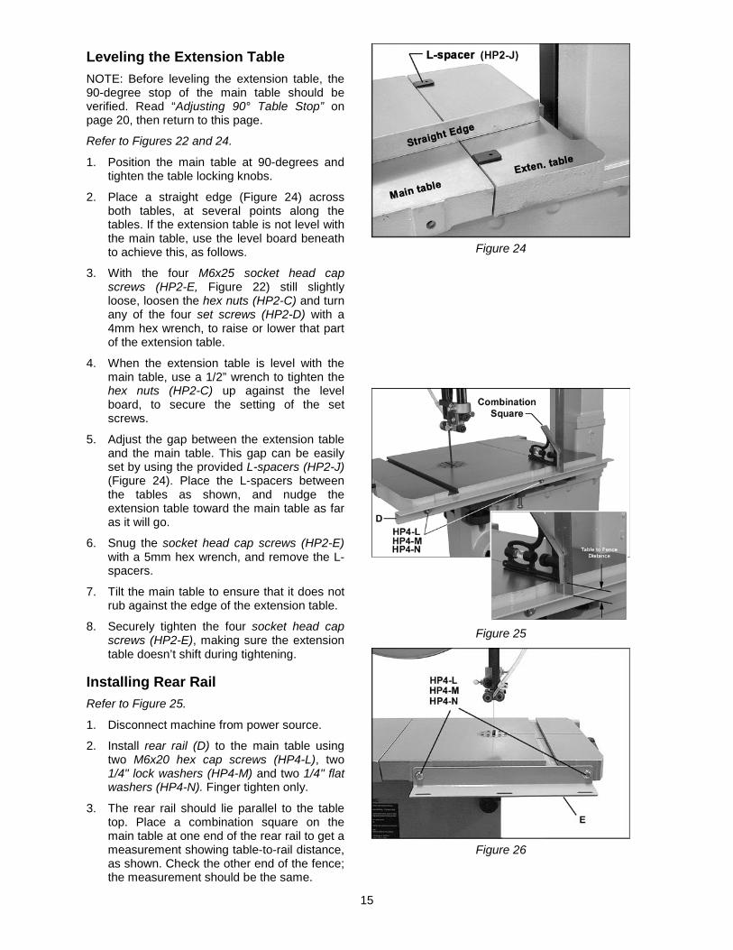
Leveling the Extension Table NOTE: Before leveling the extension table, the 90-degree stop of the main table should be verified. Read “Adjusting 90° Table Stop” on page 20, then return to this page.
Refer to Figures 22 and 24.
1. Position the main table at 90-degrees and tighten the table locking knobs.
2. Place a straight edge (Figure 24) across both tables, at several points along the tables. If the extension table is not level with the main table, use the level board beneath to achieve this, as follows.
3. With the four M6x25 socket head cap screws (HP2-E, Figure 22) still slightly loose, loosen the hex nuts (HP2-C) and turn any of the four set screws (HP2-D) with a 4mm hex wrench, to raise or lower that part of the extension table.
4. When the extension table is level with the main table, use a 1/2” wrench to tighten the hex nuts (HP2-C) up against the level board, to secure the setting of the set screws.
5. Adjust the gap between the extension table and the main table. This gap can be easily set by using the provided L-spacers (HP2-J) (Figure 24). Place the L-spacers between the tables as shown, and nudge the extension table toward the main table as far as it will go.
6. Snug the socket head cap screws (HP2-E) with a 5mm hex wrench, and remove the L-spacers.
7. Tilt the main table to ensure that it does not rub against the edge of the extension table.
8. Securely tighten the four socket head cap screws (HP2-E), making sure the extension table doesn’t shift during tightening.
Installing Rear Rail Refer to Figure 25.
1. Disconnect machine from power source.
2. Install rear rail (D) to the main table using two M6x20 hex cap screws (HP4-L), two 1/4" lock washers (HP4-M) and two 1/4" flat washers (HP4-N). Finger tighten only.
3. The rear rail should lie parallel to the table top. Place a combination square on the main table at one end of the rear rail to get a measurement showing table-to-rail distance, as shown. Check the other end of the fence; the measurement should be the same.
Figure 24
Figure 25
Figure 26

16
4. Shift either end of the fence as needed to gain identical distance from table top.
5. Tighten both screws in the rear rail using a 10mm wrench.
Installing Front Rail and Rip Fence Refer to Figures 26 through 29.
1. Install front rail (E, Figure 26) to the main table using two M6x20 hex cap screws (HP4-L), two 1/4" lock washers (HP4-M) and two 1/4" flat washers (HP4-N). Finger tighten only at this time.
2. Install guide rail (B, Figure 27) to the slots in the front rail using three M6x20 hex cap screws (HP4-L), three 1/4" lock washers (HP4-M) and three 1/4" flat washers (HP4-N). Tighten with a 10mm wrench.
3. Lift up the fence handle and hook the fence assembly over the rear rail, and onto the guide rail, as shown in Figure 28. The sliding pad (Figure 29) should ride along the top of the rear rail. To adjust, loosen hex nut and rotate sliding pad as needed. Retighten hex nut.
4. Push handle all the way down to lock fence to guide rail. Raise handle to slide fence assembly along table.
Setting Fence-to-Table Gap The gap between the bottom of the rip fence and the table top should be high enough that the fence will not scrape along the table, yet low enough that thin workpieces won’t slip beneath it. The gap should be equal along the length of the fence. Adjust as follows:
Refer to Figures 29 and 30.
1. Lock the fence assembly to the front rail by pushing the fence handle down. The front rail screws should still have “play” in them.
2. Lift up on both guide rail and fence together until the fence/table gap at the front edge of the table is acceptable.
3. Tighten both screws on the front rail (HP4-L, Figure 26) with a 10mm wrench.
4. Adjust the height of the sliding pad at the rear of the fence (Figure 29) if further adjustment is needed to even the gap along the length of the fence.
Figure 27
Figure 28
Figure 29
Figure 30

17
Aligning Fence to Blade Refer to Figure 31.
1. Place the table at 90-degrees. (Make sure the 90° Table Stop setting has been verified – see page 20.)
2. Lock the fence to the guide rail with the handle.
3. Place a square on the table and against the fence, as shown in Figure 31.
4. If the fence is not square to the table, slightly loosen the two screws in the front rail (see Figure 26) and raise or lower one end of the front rail assembly until fence is square to table.
5. Re-tighten screws. The fence face is now square to the table, and thus parallel to the blade.
The fence must also be set so that it aligns with the blade front-to-back, as follows:
6. Move the fence so that it just contacts the blade without bending it, and lock the fence to the guide rail.
7. Check that the fence is aligned with the blade; that is, it contacts front and back of blade evenly. If the fence does not align with the blade, loosen the four socket head cap screws (D, Figure 31).
8. Align the fence with the blade, then tighten the four socket head cap screws.
Checking zero setting Refer to Figure 31.
1. With the fence now aligned with the blade, and still contacting the blade as shown in Figure 31, check to see that the pointer is aligned with zero on the guide rail scale.
2. If minor adjustment is necessary, loosen the screw that holds the pointer in place, and adjust the pointer. Re-tighten the screw.
3. If major adjustment is necessary, loosen the guide rail screws (HP4-L, Figure 27), and slide the entire fence/guide rail together until the fence just contacts the blade. Re-tighten guide rail screws, and make further minor adjustment with the pointer.
NOTE: The pointer’s zero position should be tested later by cutting a straight piece of stock, carefully measuring its width, and comparing it to the scale reading.
Figure 31

18
Resaw Guide Refer to Figure 32.
For resawing operations, attach the resaw guide (HP4-A) to the fence using the knob (HP4-B) through the slotted hole. Position the resaw guide so that it is centered approximately with the front edge of the saw blade.
The resaw guide offers a taller, single-point contact surface that allows pivoting of the workpiece in order to keep the blade on the cutting line.
Blower Nozzle Refer to Figures 33 and 34.
1. The air hose, which is already connected to the saw body, should be inserted through the hole in the stand (visible in Figure 16) and connected to the nozzle of the air regulator on the motor (Figure 33). Use a lighter or match to briefly heat the end of the hose so that it will slip over the nozzle. As it cools, it will form a tight seal over the nozzle.
2. Attach the plate (HP1-A) to the blade guide assembly.
3. Connect the top end of the air hose to the plate (HP1-A) with the M5x12 pan head screw (HP1-D) through the cord clamp (HP1-C). Heat the end of the hose with a lighter or match, then push the wide end of the nozzle (HP1-B) into the hose; the tapered end points down toward the table as shown.
Work Lamp Refer to Figure 35.
The goose-neck lamp uses a medium base light bulb (not provided) which should be 60 watts or less. The work lamp is operated independently of the main saw switch.
IMPORTANT: If you are using 115 volt power for the band saw, use a standard 110 volt light bulb. If you are using 230 volt power for the band saw, discontinue use of the provided lamp, and use an alternate lamp with an independent power cord.
Figure 32
Figure 33
Figure 34
Figure 35

19
Installing Quick Tension Lever Refer to Figure 36.
Install the quick tension lever (M) onto the shaft as shown, and tighten the two set screws using a 3mm hex wrench. The movement of the blade tension lever is explained under “Installing Blades”.
Stand Attachments Refer to Figure 37.
1. Mount the two miter gauge hooks (HP3-B) to the side of the stand with two M8x16 carriage bolts (HP3-E) and two M8 flanged hex nuts (HP3-F). Position the hooks at an angle, similar to that shown in Figure 38. The miter gauge can be stored in these hooks.
2. Mount the blade hook (HP3-C) with two M4x10 pan head screws (HP3-H) as shown. The blade hook can store a rolled-up spare blade.
3. Mount the two fence hooks (HP3-A) to the opposite side of the stand with two M8x16 carriage bolts (HP3-E) and two M8 flanged hex nuts (HP3-F). The rip fence can be stored in these hooks when not in use.
Dust Collection Refer to Figure 38.
The use of a dust collection system (not provided) is strongly advised when using the band saw. It will help keep your shop clean, and reduce the risk of health problems due to wood dust inhalation. The dust collector should have sufficient capacity for this size band saw (minimum 350 cubic feet per minute).
Connect a 4” diameter dust collection hose (not provided) to the port at the back of the band saw, and secure tightly with a hose clamp, as shown.
Note: Dryer vent hose is not suitable for dust collection purposes.
Riser Block Accessory A Riser Block kit (stock no. 1791217, not provided) is available as an accessory. When installed, it increases resaw capacity (workpiece height capacity) to 12 inches. If you have purchased the Riser Block, consult the instruction sheet that accompanies it.
Figure 36
Figure 37
Figure 38

20
Adjustments Tilting the Table
Unplug the machine from the power source before making any repair or adjustment.
Refer to Figure 39.
1. Loosen the table locking knobs.
2. Tilt table up to 45 degrees to the right. The angle is indicated on the trunnion scale.
3. Tighten the table locking knobs.
4. You can place a measuring device on the table and against the blade to verify the 45° setting.
Adjusting 90° Table Stop Refer to Figures 39 and 40.
1. Disconnect machine from power source.
2. Loosen table locking knobs and tilt table to the left until it rests against the table stop screw.
3. Use a square placed on the table and against the blade, as shown in Figure 40, to verify that the table is 90 degrees to the blade. Make sure the table insert is level with the table surface, to ensure an accurate reading.
4. If an adjustment is necessary, tilt the table out of the way and tighten the table locking knobs.
5. Loosen jam nut (Figure 39) and turn table stop screw left or right to raise or lower the stop. Tighten jam nut down against the trunnion support to hold table stop screw in place.
6. Unlock the table and tilt it back on to the table stop screw to confirm table is 90 degrees to the blade. Repeat this process as necessary until table is 90 degrees to the blade.
7. Make sure pointer (Figure 39) indicates zero. If it does not, loosen screw and move pointer to align with zero. Re-tighten screw.
NOTE: After adjusting the 90-degree stop, it may be necessary to re-set the extension table so it is level with the main table. See “Leveling the Extension Table.”
Figure 39
Figure 40

21
Table Aligned with Blade For accurate crosscuts using the miter gauge, the table (i.e. miter slot) must be aligned with the blade. This alignment has been set by the manufacturer, but the operator may wish to verify it, as follows. NOTE: This procedure works best with a wide blade.
Refer to Figure 41.
1. Place a straightedge along the side of the blade, with very light pressure (do not deflect the blade). The straightedge should contact both front and back of blade.
2. Measure carefully with a fine rule from the straightedge to the edge of the miter slot. Do this at front and back of the table; the distance should be the same.
3. If the miter slot is not aligned with the blade, slightly loosen the six screws holding the trunnions to the table.
4. Nudge the table as needed, until the miter slot is aligned with blade (distances are the same front to back).
5. Tighten trunnion screws. (NOTE: After this adjustment, the alignment of fence to blade may need to be re-checked. See “Aligning Fence to Blade” on page 17.)
Installing Blades
Unplug the machine from the power source before removing or installing blades.
The PWBS-14CS Band Saw is provided with a 3/8” wide x 0.020 thick x 93.5” long, 6TPI blade.
Refer to Figure 42.
The blade tension lever is a patented Carter® Quick-Release™ lever, and has three positions: high (tension), middle (partial tension), and low (blade release). Push the lever up slightly, then out, and move it into position, allowing it to rest on the appropriate ledge of the block.
1. Disconnect machine from power source.
2. Move tension lever to blade release position, as shown in Figure 42.
(Note: When using the larger width blades, it may also become necessary to loosen the tension knob to release all tension.)
3. Remove the table insert and the table pin.
4. Open both wheel guards.
5. Back off the upper and lower guide bearings so that nothing conflicts with the blade.
Figure 41
Figure 42

22
6. Remove the current blade from the upper wheel, then the lower wheel. Turn blade to direct it through the slot in the table.
New blades are usually packaged in coiled position. Use gloves and grasp the coil with one hand while slowly uncoiling the blade with the other hand.
7. Guide new blade through table slot. Place blade in upper and lower blade guides, and around upper and lower wheels.
Note: Make sure blade teeth point forward and down toward the table. If the teeth won’t point downward no matter how you orient the blade, then the blade is twisted inside-out. Remove blade and, using gloves, twist it into correct orientation, then re-install.
8. Position blade so it lies on the center of both upper and lower wheels.
9. Raise tension lever to partial tension position.
10. Re-install table insert and table pin.
11. Tension and track the blade before operating saw. Proceed to "Blade Tension" and “Blade Tracking".
Blade Tension Refer to Figure 43.
1. Disconnect machine from power source.
2. Place tension lever in full tension position (see Figure 42).
3. Turn blade tension knob (Figure 43) clockwise to tension blade. A gauge on the upper wheel slide bracket indicates the approximate tension according to the width of the blade. Initially, set the blade tension to correspond to blade width.
The tension lever must be in highest (tension) position when setting blade tension. Failure to comply may cause damage to locating block at base of lever.
As you become familiar with the saw, you may find it necessary to change the blade tension from the initial setting. Changes in blade width and the type of material being cut will have an effect on blade tension. Keep in mind that too little or too much blade tension can cause blade breakage.
TIP: If the band saw is to sit idle for a period of time while the blade is installed, place tension lever in partial tension position; this will help prevent blade fatigue and tire deformation, and save wear on bearings and band wheels.
Figure 43

23
Blade Tracking
Disconnect machine from power source. Do not adjust blade tracking with the machine running.
“Tracking” refers to how the blade is positioned on the wheels while in motion. The blade should track approximately in the center of both wheels, as shown in Figure 44. Tracking on the PWBS-14CS Band Saw has been factory-adjusted; however, it should be checked periodically, including after every blade change.
Refer to Figure 45.
1. The blade must be properly tensioned before adjusting blade tracking. Make sure blade guides and blade bearings do not interfere with the blade.
2. Place the tension lever at full tension position.
3. Open the upper door and rotate the upper wheel forward by hand. Observe the position of the blade on the wheel - it should be in the center.
4. If the blade tends to shift to one side or the other of the wheel, loosen wing nut (Figure 45).
5. If the blade is tracking toward the front edge of the wheel, rotate the tracking knob clockwise – the upper wheel will tilt toward the back and the blade will move to the center of the wheel.
If the blade is tracking toward the back edge of the wheel, rotate the tracking knob counterclockwise: the upper wheel will tilt toward the front and the blade will move to the center of the wheel.
IMPORTANT: This adjustment is sensitive; perform it in small increments and give the blade time to react to the changes, as you continue to rotate the wheel.
6. When blade is tracking properly at the center of the wheel, re-tighten the wing nut.
7. Turn on saw and verify proper tracking while the machine is running.
8. If further tracking adjustments are needed, disconnect from power, and repeat instructions above.
Guide Post and Upper Blade Guard Refer to Figure 46.
1. Disconnect machine from power source.
Figure 44
Figure 45
Figure 46

24
2. Loosen lock knob and raise or lower upper blade guide assembly to approximately 3/16” above the material being cut.
3. Tighten lock knob.
4. The guide post (Figure 46) is spring loaded. To adjust the tension on the spring, unscrew and completely remove knob, then tighten or loosen set screw, until desired tension is reached. Re-install knob.
Upper Bearing Guides Refer to Figures 47, 48, 49.
1. Disconnect machine from power source.
2. Blade must already be tensioned and tracking properly.
3. Loosen thumb screw (A, Figure 47) and move guide block by turning knob (B) so that the front of the guide wheels (C) are just behind the gullet (curved area at base of tooth) of the blade, as shown in Figure 48. This distance is usually about 0.016” (or 1/64”).
4. Tighten thumb screw (A, Figure 47).
5. Loosen the socket screw (D) and turn the screw (E) on each guide wheel to move the guide wheels about 0.004” from the blade. (A quick way to set this distance is to place a crisp dollar bill, which is approximately .004” thick, between guide wheel and blade, and move the guide until it just contacts the bill.)
6. Tighten socket screw (D) when adjustment is satisfactory.
Thrust Bearing
The thrust bearing (F, Figure 49) supports the back edge of the blade during operation, and is set so that the blade will contact it only when the blade is under pressure during a cut.
7. Loosen thumb screw (G, Figure 49) and turn knob (H) to move the thrust bearing (F) in or out until the bearing is approximately 0.016” (or 1/64”) behind the blade. You can use a feeler gauge to set this distance, or simply place a crisp dollar bill folded twice (four thicknesses) between the thrust bearing and the blade. (A dollar bill is approximately 0.004” thick, so four thicknesses provides the necessary distance.)
8. Tighten thumb screw (G, Figure 50).
Lower Bearing Guides Refer to Figure 50.
1. Disconnect machine from power source.
Figure 47
Figure 48
Figure 49
Figure 50

25
2. Blade must already be tensioned and tracking properly.
3. Loosen thumb screw (J) and move guide block by turning knob (K) so that the front of the guide wheels (L) are just behind the gullet (curved area at base of tooth) of the blade.
4. Tighten thumb screw (J).
Thrust Bearing
5. Loosen thumb screw (M) and turn knob (N) to move the support bearing (O) in or out until the bearing is approximately 0.016” (or 1/64") behind the blade. You can use a feeler gauge to set this distance, or simply place a dollar bill folded twice (four thicknesses) between the support bearing and the blade. (A dollar bill is .004” thick, so four thicknesses provides the necessary distance.)
6. Tighten thumb screw (M).
7. Loosen the socket screw (P) and turn the screw (R) on each guide wheel to move the guide wheels about .004” from the blade. Tighten socket screw (P) when finished.
Miter Gauge Refer to Figures 51, 52.
A miter gauge is provided for crosscutting. Slide the miter gauge into the T-slot from the edge of the table.
To use the miter gauge, loosen the handle and rotate the gauge body until the desired angle on the scale lines up with the pointer. Tighten handle.
For precise crosscuts, the 90° angle of the miter gauge to the blade can be verified as follows (Refer to Figure 52). A wide blade works best for this procedure.
1. Set the miter gauge at 90°.
2. Place a square against the miter gauge and against the blade, as shown.
3. Adjust the miter gauge until the square lies flush against both it and the blade.
4. Loosen the screw and shift the pointer as needed. Retighten screw.
The miter gauge, when not in use, can be placed into the hooks on the stand. See Figure 53. Loosen the miter gauge handle, and slide the miter gauge into the top hook. Pivot the miter gauge bar into the lower hook, then tighten the miter gauge handle to secure the miter gauge to the stand.
Figure 51
Figure 52
Figure 53

26
On/Off Switch The band saw is equipped with a push-button switch that will accept a safety padlock (not included). To safeguard your machine from unauthorized operation and accidental starting by young children, the use of a padlock is highly recommended – see Figure 54.
Maintenance Before doing maintenance,
disconnect machine from electrical supply by pulling out the plug or switching off the main switch! Failure to comply may cause serious injury.
Clean the band saw regularly to remove any resinous deposits and sawdust. Use a brush, vacuum or compressed air to blow out excess dust. (Wear safety goggles while doing this.)
Keep the miter slot in the table free of dust and debris. Keep the guide bearings clean and free of resin. Use a commercially available gum and pitch remover if needed.
Keep the guide post clean; occasionally apply a light coat of oil.
Oil any pins, shafts, and joints. Do not get oil on pulleys or belts.
Bearings on the band saw are sealed for life and do not require attention.
Check that the cleaning brush over the lower wheel is working properly; adjust if necessary.
Remove any deposits from the band wheels and tires to avoid vibration and blade breakage. NOTE: Do not use solvents around tires. If signs of wear or deformation occur, replace the tires.
The table surface must be kept clean and free of rust for best results. If rust appears, use a mixture of household ammonia, a good commercial detergent and #000 steel wool. Alternatively, commercial rust removers can be found at many hardware stores.
Apply a light, protective coating over the table, such as paste wax. Products in aerosol form are also available in hardware stores and supply catalogs. Whatever method is chosen, the coating should protect the metal and provide a smooth surface, without staining the wood.
Figure 54

27
Blade Selection Using the proper blade for the job will increase the operating efficiency of your band saw, help reduce necessary saw maintenance, and improve your productivity. Thus, it is important to follow certain guidelines when selecting a saw blade.
Here are factors to consider when selecting a blade:
• The type of material you will be cutting. • The thickness of the workpiece. • The features of the workpiece, such as
bends or curves with small radii. These factors are important because they involve basic concepts of saw blade design. There are five (5) blade features that are normally changed to meet certain kinds of sawing requirements. They are:
1. width 2. pitch (number of teeth per inch) 3. tooth form (or shape) 4. the “set” of the teeth 5. the blade material itself
Width Band saw blades come in different standard widths, measured from the back edge of the blade to the tip of the tooth. Generally, wider blades are used for ripping or making straight cuts, such as resawing. Narrower blades are often used when the part being cut has curves with small radii. When cutting straight lines with a narrow blade, the blade may have a tendency to drift (see “Blade Lead”).
Pitch Pitch is measured in “teeth per inch” (T.P.I.) and can be constant or variable. Figure 55 shows blades with different pitches.
Figure 55
A fine pitch (more teeth per inch) will cut slowly but more smoothly. A coarse pitch (fewer teeth per inch) will cut faster but more roughly.
As a rule of thumb, the thicker the workpiece, the coarser will be the blade pitch. If you have to cut a hard or very brittle material, you will probably want to use a blade with a finer pitch in order to get clean cuts.
Using a blade with too few teeth may cause vibration and a rough cut, while too many teeth may cause the gullets to fill with sawdust and overheat the blade.
As a general rule, try to use a blade that will have from 6 to 12 teeth in the workpiece at any given time.
Shape Figure 56 shows common types of tooth shape, or form. Tooth shape has an effect on cutting rate.
Figure 56 – Blade Tooth Shape
The Regular, or standard blade, has evenly spaced teeth that are the same size as the gullets, and a zero-degree rake (i.e. cutting angle). These offer precise, clean cuts at slower rates. It is usually a good choice for cutting curves and making crosscuts.
The Skip type has fewer teeth and larger gullets with a zero rake. It allows faster cutting rates than the Regular type, with a slightly coarser finish. It is useful for re-sawing and ripping thick stock, as well as cutting softwoods.
The Hook type blade has larger teeth and gullets and a positive rake angle for more aggressive, faster cutting when re-sawing or ripping thick stock, especially hardwoods.
Variable-tooth blades combine features of the other shapes, with tooth style and spacing varying on the same blade. This produces smooth cuts while dampening vibration.

28
Set The term “set” refers to the way in which the saw teeth are bent or positioned. Bending the teeth creates a kerf that is wider than the back of the blade. This helps the operator more easily pivot a workpiece through curve cuts, and decreases friction between blade and workpiece on straight cuts.
Set patterns are usually selected depending upon the type of material that needs to be cut. Three common set patterns are shown in Figure 57.
Figure 57
Generally, the Raker set is used for cutting metal workpieces; the Wavy set, when the thickness of the workpiece changes, such as cutting hollow tubing or structurals. The Straight, or Alternate, set is the one most used for woodworking blades, and is also used to cut plastics.
Material Band saw blades can be made from different types of metals. The most common include spring steel, carbon steel, bimetal (alloy steel equipped with a high speed cobalt steel edge welded to it), or carbide tips.
Because of the importance of blade selection, it is recommended that you use the blade selection guide on page 35. Also, listening to experienced band saw users will provide valuable information as to the types of blades currently on the market along with their pros and cons.
Blade Breakage Band saw blades are subject to high stresses and breakage may sometimes be unavoidable. However, many factors can be controlled to help prevent most blade breakage. Here are some common causes for breakage:
1. Misalignment of the blade guides. 2. Feeding workpiece too quickly. 3. Using a wide blade to cut a tight radius
curve. 4. Excessive tension. 5. Teeth are dull or improperly set. 6. Upper guides are set too high off the
workpiece. 7. Faulty weld on blade. Although not essential, some users round or “stone” the back edge of their blade. This is done by placing a sharpening stone on the table and in light contact with the back corners of the blade as the blade is running. Rounding can help the back blade edge move more smoothly through the kerf, smooths the weld, and helps prevent cracks from starting at the back corners.

29
Operation The following section contains basic information, and is not intended to cover all possible applications or techniques using the Band Saw. Consult published sources of information, acquire formal training, and/or talk to experienced Band Saw users to gain proficiency and knowledge of band saw operations. (The Figures used may or may not show your particular saw model, but the procedures are identical.)
General Procedure 1. Make sure the blade is adjusted correctly for
tension and tracking, and that upper and lower guide bearings and thrust bearings are set in proper relation to the blade.
2. Adjust guide post so that the guide bearings are just above the workpiece (about 3/16”) allowing minimum exposure to the blade.
3. If using the fence, move it into position and lock it to the guide rail. If you are using the miter gauge for a crosscut, the fence should be moved safely out of the way.
4. Turn on the band saw and allow a few seconds for the machine to reach full speed.
Whenever possible, use a push stick, hold-down, power feeder, jig, or similar device while feeding stock, to prevent your hands getting too close to the blade.
5. Place the straightest edge of the workpiece against the fence for a rip cut; or against the miter gauge for a crosscut. Push the workpiece slowly into the blade, while also keeping it pressed against the fence or held against the miter gauge. Do not force the workpiece into the blade.
Some further operating tips:
Make relief cuts whenever possible. A relief cut is an extra cut made through the waste portion of a workpiece up to the layout line. When that intersection is reached by the blade while following the layout line, the waste portion comes free. This helps prevent pinching of the back edge of the blade in the cut.
When cutting, do not overfeed the blade; overfeeding will reduce blade life, and may cause the blade to break.
When cutting long stock, the operator should use roller stands, support tables, or an assistant to help stabilize the workpiece.
Ripping Ripping is cutting lengthwise down the workpiece, and with the grain (of wood stock). See Figure 58. Always use a push stick or similar safety device when ripping narrow pieces.
Figure 58
Crosscutting Crosscutting is cutting across the grain of the workpiece, while using the miter gauge to feed the workpiece into the blade.
The right hand should hold the workpiece steady against the miter gauge, while the left hand pushes the miter gauge past the blade, as shown in Figure 59.
Figure 59
Do not use the fence in conjunction with the miter gauge. The offcut of the workpiece must not be constrained during or after the cutting process.
Using the fence in conjunction with the miter gauge can cause binding and possible damage to the blade.

30
Resawing Resawing is the process of slicing stock to reduce its thickness, or to produce boards that are thinner than the original workpiece, such as veneers.
The ideal blade for resawing is the widest one the machine can handle, as the wider the blade the better it can hold a straight line.
Resawing can be performed using the rip fence or the resaw guide. When using the rip fence, use a push block, push stick, or similar device to keep your hands away from the blade. The resaw guide offers a pivot point by which you can carefully follow your layout line; it is especially useful for sawing curves, when the fence can’t be used and it’s difficult to control the cut freehand.
Figure 60 demonstrates resawing with the rip fence; Figure 61, with the resaw guide.
Figure 60
Figure 61
Blade Lead Blade lead, or drift, is when the blade begins to wander off the cutting line even when the band saw rip fence is being used. Figure 62 shows an example of blade lead.
It is more common with small, narrow blades, and is almost always attributable to poor blade quality, or lack of proper adjustments. Inspect the band saw for the following:
• Fence is not parallel to miter slot and blade. • Blade is not tensioned correctly. • Blade is dull. • Teeth have too much “set” on one side of
the blade. • Workpiece is being fed too quickly.
Figure 62
If the blade is suspect, but replacing it is not currently an option, the blade lead can be temporarily compensated for by skewing the fence:
1. Cut a scrap piece of wood about the same length as the band saw table, and joint one edge along its length, or rip it on a table saw to give it a straight edge.
2. Draw a line on the board parallel with the jointed, or straight edge of the board.
3. Move the band saw fence out of the way, and carefully make a freehand cut along your drawn line on the board. Stop about midway on the board, and shut off the band saw (allow the blade to come to a complete stop) but do not allow the board to move.
4. Clamp the board to the table.
5. Loosen the four hex cap screws on the fence and slide the fence over, lining it up against the board. Lock the fence down.
6. Re-tighten the four hex cap screws.
NOTE: Skewing the fence to correct blade lead is effective for that particular blade; when a new blade is installed, the fence will need re-adjustment and re-squaring to miter slot. See appropriate sections in this manual.
31
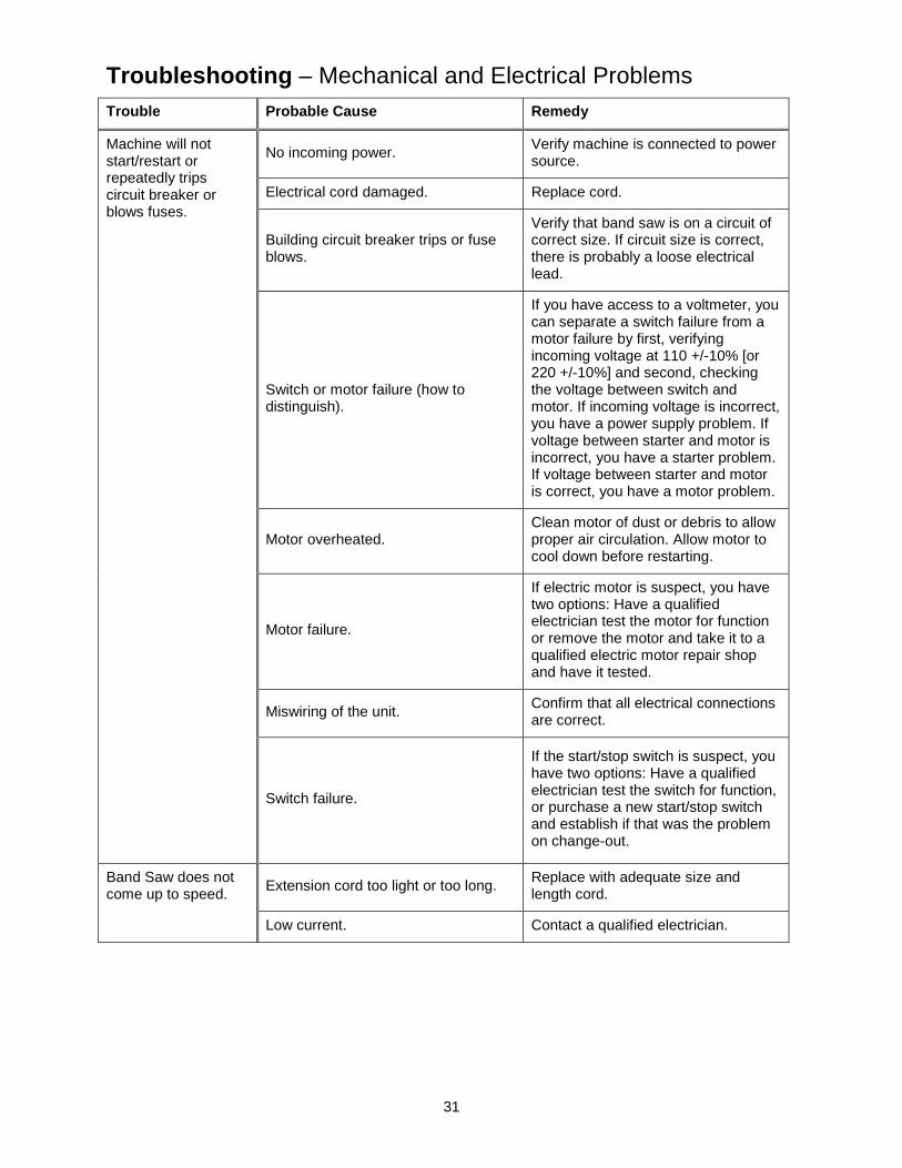
Troubleshooting – Mechanical and Electrical Problems Trouble Probable Cause Remedy
Machine will not start/restart or repeatedly trips circuit breaker or blows fuses.
No incoming power. Verify machine is connected to power source.
Electrical cord damaged. Replace cord.
Building circuit breaker trips or fuse blows.
Verify that band saw is on a circuit of correct size. If circuit size is correct, there is probably a loose electrical lead.
Switch or motor failure (how to distinguish).
If you have access to a voltmeter, you can separate a switch failure from a motor failure by first, verifying incoming voltage at 110 +/-10% [or 220 +/-10%] and second, checking the voltage between switch and motor. If incoming voltage is incorrect, you have a power supply problem. If voltage between starter and motor is incorrect, you have a starter problem. If voltage between starter and motor is correct, you have a motor problem.
Motor overheated. Clean motor of dust or debris to allow proper air circulation. Allow motor to cool down before restarting.
Motor failure.
If electric motor is suspect, you have two options: Have a qualified electrician test the motor for function or remove the motor and take it to a qualified electric motor repair shop and have it tested.
Miswiring of the unit. Confirm that all electrical connections are correct.
Switch failure.
If the start/stop switch is suspect, you have two options: Have a qualified electrician test the switch for function, or purchase a new start/stop switch and establish if that was the problem on change-out.
Band Saw does not come up to speed. Extension cord too light or too long. Replace with adequate size and
length cord.
Low current. Contact a qualified electrician.

32
Troubleshooting – Operating Problems Trouble Probable Cause Remedy
Table tilt does not hold position under load.
Table locking knobs are not tight. Tighten locking knobs .
Table will not tilt. Trunnion is not lubricated. Grease the trunnion.
Trunnion is jammed. Disassemble and replace jammed parts.
Saw vibrates excessively.
Stand is on uneven floor. Re-position on flat, level surface.
Drive belt is too slack, or worn. Increase tension on drive belt. Replace belt if worn.
Motor plate screws or other hardware on saw is loose. Tighten all hardware.
Incorrect choice of saw blade pitch. Check blade selection chart and use correct blade.
Saw dust or debris on band wheel. Or tire is worn/damaged.
Keep band wheels clean. Replace tires if necessary.
Low shop voltage. Contact a qualified electrician.
Surface finish on workpiece is rough.
Saw blade speed is too low. Increase speed.
Saw blade pitch is too coarse. Change to finer pitch blade.
Saw blade cutting inaccurately. Cuts are not straight.
Blade mounted incorrectly. Teeth should point downward.
Angle pointer not set correctly. Check blade with square and adjust pointer.
Table stop not adjusted correctly. Check blade with square and adjust stop.
Gum or pitch on blade. Clean blade.
Worn blade teeth or damaged blade. Replace blade.
Fence not parallel to blade. Align fence properly (see page 17).
Miter gauge adjusted improperly. Adjust miter gauge (see page 25)
Incorrect adjustment of blade guides. Adjust blade guides properly (see pages 24-25).
Workpiece being fed too strongly. Reduce feed force.
Upper blade guides not located close enough to workpiece.
Guides should be about 3/16” above workpiece.
Incorrect choice of saw blade for that particular cutting operation. Change to correct blade.
Blade tension too light. Increase tension (see page 22).

33
Trouble Probable Cause Remedy
“Blade lead” occurs (blade wanders during cut)
Fence not aligned with blade. Check and adjust fence (see page 17)
Wood is warped. Select different wood.
Excessive feed rate Reduce feed rate.
Incorrect blade being used for the particular cut being made.
Change blade to correct type.
Blade tension improperly set. Set blade tension according to blade size.
Bearing guides not set properly. Adjust guides (see pages 24-25).
Blade cannot be tensioned properly.
Tension spring is fatigued. Replace tension spring (contact service representative).
Blade binds in the workpiece.
Incorrect blade tension or damaged blade. Correct accordingly.
Blade too wide for desired radius. Select narrower blade. See chart on page 35.
Blade forms cracks at base of teeth.
Teeth not suitable for particular job, or are incorrectly set.
Replace with proper blade for job.
Blade thickness not suitable for band wheel diameter. Replace with proper thickness blade.
Blade sharpened incorrectly, becomes overheated. Sharpen blade properly or replace.
Band wheels have become misaligned. Contact service representative.
Cracks on back edge of blade. Workpiece being fed too quickly. Reduce feed speed to lessen strain
on the blade.
Welding on blade not perfectly aligned.
Eliminate the welded part, and re-weld properly; or acquire a new blade. Round the back edge of a new blade.
Thrust bearing is worn; caused by constant contact with back of blade.
Replace thrust bearing. Adjust new bearing according to instructions.
Blade breaks prematurely.
Feeding workpiece too quickly. Reduce feed force.
Blade guides misaligned. Set bearing guides appropriate distance from blade.
Blade pitch too coarse, or wrong size blade for particular cut (e.g., wide blade to cut a tight radius).
Refer to blade selection chart; use appropriate blade for the operation.
Blade overheated during welding. Replace blade, or have blade annealed, or eliminate brittle part and weld correctly.

34
Trouble Probable Cause Remedy
Blade cooled too rapidly after welding.Replace blade, or have blade annealed, or eliminate brittle part and weld correctly.
Thrust bearing not properly supporting blade, or guide post/side bearings set too high allowing flex.
Check all guide bearings for correct position and signs of wear. Adjust or replace as needed.
Blade tensioned too tightly. Reduce tension (see page 22).
Blade breaks close to weld. Blade overheated during welding. Have blade annealed, or eliminate
brittle part and weld correctly.
Blade cooled too rapidly after welding. Have blade annealed, or eliminate brittle part and weld correctly.
Premature dulling of saw teeth. Blade “pitch” too fine. Refer to blade selection chart. Use
blade with coarser pitch.
Feed pressure too light. Increase feed pressure.
Cutting rate too low. Increase feed pressure and cutting rate.
Incorrect choice of blade. Re-examine material. Select proper blade from the chart.
Chipped tooth or foreign object lodged in cut.
Stop the saw and remove lodged particle. Replace blade if damaged.
Optional Accessories 1791217 ...... 6” Riser Block Kit 2042377 ...... Mobile Base for PWBS14-CS Band Saw

35
Blade Selection Guide Identify the material and thickness of your workpiece. The chart will show the recommended PITCH, blade TYPE, and FEED RATE.
Key: H – Hook L – Low S – Skip M – Medium R – Regular H – High Example: 10/H/M means 10 teeth per inch / Hook Type Blade / Medium Feed
For Radius Cutting Study the part drawing or prototype, or actually measure the smallest cutting radius required, and locate this radius (in inches) on the chart at the right. Follow the curve to where the approximate blade width is specified. If a radius falls between two of the curves, select the widest blade that will saw this radius.
This procedure should be used for making initial blade selections. These recommendations can, of course, be adjusted to meet specific requirements of a cutting job. Compromises may be necessary if you cannot find all needed specifications in a single blade.

36
Replacement Parts To order parts or reach our service department, call 1-800-274-6848, Monday through Friday (see our website for business hours, www.powermatic.com). Having the Model Number and Serial Number of your machine available when you call will allow us to serve you quickly and accurately.
Parts List: Body Assembly
Index No. Part No. Description Size Qty 1 ................ PWBS14-101 ............ Base......................................................................... ...................................... 1 2 ................ PWBS14-102 ............ Pin............................................................................ ...................................... 4 3 ................ BB-6204VV ............... Ball Bearing ............................................................. 6204VV ......................... 2 4 ................ PWBS14-104 ............ Lower Wheel Shaft .................................................. ...................................... 1 5 ................ 6291489 .................... Key........................................................................... 5 x 5 x 20 mm ............... 2 6 ................ PWBS14-106 ............ Retaining Ring ......................................................... S20 ............................... 1 7 ................ PWBS14-107 ............ Pulley ....................................................................... ...................................... 1 8 ................ TS-1523031 .............. Socket Set Screw .................................................... M6 x 10 ......................... 2 9 ................ PWBS14-109 ............ Hex Head Bolt.......................................................... M16 x 55 ....................... 1 10 .............. TS-155010 ................ Flat Washer ............................................................. M16 ............................... 2 11 .............. TS-154010 ................ Hex Nut .................................................................... M16 ............................... 1 12 .............. PWBS14-112 ............ Hex Stud .................................................................. ...................................... 2 13 .............. PWBS14-113 ............ Lower Hinge............................................................. ...................................... 1 14 .............. TS-1534041 .............. Phillips Flat Head Machine Screw ........................... M5 x 10 ......................... 4 15 .............. PWBS14-115 ............ Hex Head Bolt.......................................................... ...................................... 2 16 .............. PWBS14-116 ............ Catch ....................................................................... ...................................... 2 17 .............. TS-1533042 .............. Phillips Pan Head Machine Screw ........................... M5 x 12 ......................... 3 18 .............. PWBS14-118 ............ Lower Wheel ............................................................ ...................................... 1 19 .............. PWBS14-119 ............ Wheel Tire ............................................................... ...................................... 2 20 .............. TS-1550061 .............. Flat Washer ............................................................. M8 ................................. 2 21 .............. PWBS14-121 ............ Hex Cap Screw ........................................................ M8 x 25(LH) .................. 1 22 .............. PWBS14-122 ............ Upper Wheel ............................................................ ...................................... 1 23 .............. PWBS14-123 ............ Retaining Ring ......................................................... R35 ............................... 2 24 .............. BB-6202ZZ ................ Ball Bearing ............................................................. 6202ZZ ......................... 2 25 .............. PWBS14-125 ............ Lower Wheel Guard ................................................. ...................................... 1 26 .............. TS-1540083 .............. Hex Nut .................................................................... M12 x 1.25 .................... 1 27 .............. .................................. Blade (local purchase) ............................................. ...................................... 1 28 .............. PWBS14-128 ............ Upper Back Cover ................................................... ...................................... 1 29 .............. PWBS14-129 ............ Pan Head Flanged Screw ........................................ M5 x 8 ........................... 2 30 .............. PWBS14-130 ............ Tapping Screw ......................................................... M4 x 8 ......................... 12 31 .............. PWBS14-131 ............ Rear Guard Blade .................................................... ...................................... 1 32 .............. PWBS14-132 ............ Upper Hinge............................................................. ...................................... 1 33 .............. PWBS14-133 ............ Oblong Metal Washer .............................................. ...................................... 2 34 .............. PWBS14-134 ............ Tapping Screw ......................................................... M3.5 x 16(AB) ............... 2 35 .............. PWBS14-135 ............ Upper Wheel Guard ................................................. ...................................... 1 36 .............. PWBS14-136 ............ Stud Latch ............................................................... ...................................... 2 37 .............. PWBS14-137 ............ Star Washer (Internal) ............................................. M8 ................................. 2 38 .............. PWBS14-138 ............ Knob ........................................................................ M8 ................................. 2 39 .............. PWBS14-139 ............ Wheel Brush ............................................................ ...................................... 1 40 .............. TS-1540061 .............. Hex Nut .................................................................... M8 ................................. 1 57 .............. TS-1490071 .............. Hex Cap Screw ........................................................ M8 x 40 ......................... 4 58 .............. TS-1550061 .............. Flat Washer ............................................................. M8 x 18 ......................... 8 59 .............. TS-1550041 .............. Flat Washer ............................................................. M6 x 13 ......................... 4 60 .............. TS-1551061 .............. Lock Washer ............................................................ M8 ................................. 4 61 .............. TS-1540061 .............. Hex Nut .................................................................... M8 ................................. 4 63 .............. PWBS14-163 ............ Level Board ............................................................. ...................................... 1 64 .............. PWBS14-164 ............ Socket Head Cap Screw ......................................... M8 x 65 ......................... 4 65 .............. TS-1540061 .............. Hex Nut .................................................................... M8 ................................. 4 66 .............. TS-1524051 .............. Socket Set Screw .................................................... M8 x 20 ......................... 4 67 .............. PWBS14-167 ............ Spacer ..................................................................... ...................................... 4 68 .............. TS-1551041 .............. Lock Washer ............................................................ M6 ................................. 4 69 .............. TS-1503061 .............. Socket Head Cap Screw ......................................... M6 x 25 ......................... 4

37
Index No. Part No. Description Size Qty 70 .............. PWBS14-170 ............ Lower Blade Guard .................................................. ...................................... 1 71 .............. TS-1550041 .............. Flat Washer ............................................................. M6 ................................. 2 72 .............. TS-1482041 .............. Hex Cap Screw ........................................................ M6 x 20 ......................... 2 73 .............. PWBS14-173 ............ Upper Frame Arm .................................................... ...................................... 1 74 .............. PWBS14-174 ............ Knob ........................................................................ M8 ................................. 1 75 .............. PWBS14-175 ............ Steel Ball.................................................................. ...................................... 1 76 .............. PWBS14-176 ............ Spring ...................................................................... ...................................... 1 77 .............. TS-1525011 .............. Socket Set Screw .................................................... M10 x 10 ....................... 1 78 .............. PWBS14-178 ............ Switch Plate ............................................................. ...................................... 1 79 .............. PWBS14-179 ............ Switch Enclosure ..................................................... ...................................... 1 80 .............. TS-1533052 .............. Phillips Pan Head Machine Screw ........................... M5 x 16 ......................... 2 81 .............. PWBS14-181 ............ Switch ...................................................................... ...................................... 1 82 .............. TS-1550021 .............. Flat Washer ............................................................. M4 ................................. 2 83 .............. PWBS14-183 ............ Tapping Screw ......................................................... M3.5 x 12 (AB) .............. 2 84 .............. TS-1522011 .............. Socket Set Screw .................................................... M5 x 6 ........................... 1 85 .............. PWBS14-185 ............ Star Washer (External) ............................................ M5 ................................. 2 86 .............. PWBS14-186 ............ Phillips Pan Head Machine Screw ........................... M5 x 6 ........................... 2 87 .............. PWBS14-187 ............ Strain Relief ............................................................. ...................................... 2 88 .............. PWBS14-188 ............ Cord Clamp.............................................................. ...................................... 1 89 .............. TS-1533042 .............. Phillips Pan Head Machine Screw ........................... M5 x 12 ......................... 1 90 .............. PWBS14-190 ............ Power Cord (Switch To Motor) ................................ ...................................... 1 91 .............. PWBS14-191 ............ Power Cord .............................................................. ...................................... 1 .................. PWBS14-SBA-1 ........ Sliding Bracket Assembly (includes #92,111-120) .. ...................................... 1 (serial # 71210381 and higher) .................. PWBS14-SBA ........... Sliding Bracket Assembly (includes #92,111-120) .. ...................................... 1 (serial # 71210380 and lower) 92 .............. PWBS14-192 ............ Adjusting Bolt Assembly .......................................... ...................................... 1 .................. PWBS14-192-1 ......... Knob ........................................................................ M8 ................................. 1 .................. PWBS14-192-2 ......... Adjusting Bolt ........................................................... ...................................... 1 .................. PWBS14-192-3 ......... Spring Pin ................................................................ Ø3 x 18 mm .................. 1 111 ............ PWBS14-211A .......... Upper Wheel Sliding Bracket (serial# 71210381 and higher) ........................... 1 .................. PWBS14-211 ............ Upper Wheel Sliding Bracket (serial# 71210380 and lower)............................. 1 .................. TS-1522021 .............. Socket Set Screw .................................................... M5 x 8 ........................... 2 112 ............ PWBS14-212-1A ....... Upper Wheel Shaft Hinge Assembly ....................... ...................................... 1 .................. PWBS14-212-2A ....... Upper Wheel Shaft (serial# 80712360 and higher) .... ...................................... 1 .................. PWBS14-212-3 ......... Spring Pin ................................................................ Ø4 x 24 mm .................. 1 .................. PWBS14-212-4A ....... Upper Wheel Shaft Hinge (serial# 80712360 and higher) ................................ 1 .................. PWBS14-212-5 ......... Adjustable Nut ......................................................... M20 x 1.0 ...................... 1 113 ............ PWBS14-213 ............ Steel Pin .................................................................. ...................................... 2 114 ............ TS-1533042 .............. Phillips Pan Head Machine Screw ........................... M5 x 12 ......................... 1 115 ............ PWBS14-215 ............ Cord Clamp.............................................................. ...................................... 2 116 ............ PWBS14-216 ............ Coil Spring ............................................................... ...................................... 1 117 ............ PWBS14-217 ............ Indicator ................................................................... ...................................... 1 118 ............ PWBS14-218 ............ Square Nut .............................................................. M10 ............................... 1 119 ............ TS-154306 ................ Wing Nut .................................................................. M8 ................................. 1 120 ............ PWBS14-220 ............ Knob Bolt ................................................................. M8 x 55 ......................... 1 121 ............ PWBS14-221 ............ Guide Post ............................................................... ...................................... 1 122 ............ PWBS14-222 ............ Blade Guard ............................................................ ...................................... 1 123 ............ TS-1550041 .............. Flat Washer ............................................................. M6 x 13 ......................... 2 124 ............ PWBS14-224 ............ Support Plate ........................................................... ...................................... 1 125 ............ TS-1482011 .............. Hex Cap Screw ........................................................ M6 x 10 ......................... 2 126 ............ PWBS14-226 ............ Upper Support ......................................................... ...................................... 1 127 ............ PWBS14-227 ............ Adjusting Screw ....................................................... M8 x 1.0 x 40 ................ 4 128 ............ PWBS14-228 ............ Adjusting Nut ........................................................... ...................................... 4 129 ............ TS-1482031 .............. Hex Cap Screw ........................................................ M6 x 16 ......................... 1 130 ............ PWBS14-230 ............ Lower Support Bracket Post .................................... ...................................... 2 131 ............ PWBS14-231 ............ Bearing Sheath ........................................................ ...................................... 2 132 ............ TS-1482031 .............. Hex Cap Screw ........................................................ M6 x 20 ......................... 2 133 ............ PWBS14-233 ............ Thumb Screw........................................................... M6 x 16 ......................... 3 134 ............ BB-608ZZ .................. Ball Bearing ............................................................. 608ZZ ......................... 10 135 ............ TS-1550031 .............. Flat Washer ............................................................. M5 ................................. 4 136 ............ TS-2235061 .............. Socket Head Cap Screw ......................................... M5 x 6 ........................... 4 137 ............ TS-1502091 .............. Socket Head Cap Screw ......................................... M5 x 40 ......................... 2

38
Index No. Part No. Description Size Qty 138 ............ TS-1551031 .............. Lock Washer ............................................................ M5 ................................. 2 139 ............ PWBS14-239 ............ Support Bracket ....................................................... ...................................... 2 140 ............ PWBS14-240 ............ Eccentric Shaft......................................................... ...................................... 4 141 ............ PWBS14-241 ............ Spacing Sleeve ........................................................ ...................................... 1 142 ............ PWBS14-242 ............ Thumb Screw........................................................... M6 x 12 ......................... 1 143 ............ PWBS14-243 ............ Lampshade .............................................................. ...................................... 1 144 ............ PWBS14-244 ............ Lamp Holder ............................................................ ...................................... 1 145 ............ PWBS14-245 ............ Nut ........................................................................... ...................................... 1 146 ............ PWBS14-251-5 ......... Pan Head Flanged Screw ........................................ M5 x 8 ........................... 2 147 ............ PWBS14-247 ............ Flexible Pipe ............................................................ ...................................... 1 148 ............ PWBS14-248 ............ Cord Clamp.............................................................. ...................................... 1 149 ............ PWBS14-249 ............ Jet Head .................................................................. ...................................... 1 150 ............ TS-1533042 .............. Phillips Pan Head Machine Screw ........................... M5 x 12 ......................... 2 152 ............ PWBS14-252 ............ Spacer ..................................................................... ...................................... 2 153 ............ PWBS14-253 ............ Gasket ..................................................................... ...................................... 1 154 ............ PWBS14-254SN ....... Powermatic Nameplate, Small................................. ...................................... 1 155 ............ TS-1550041 .............. Flat Washer ............................................................. M6 ................................. 2 156 ............ TS-2361061 .............. Lock Washer ............................................................ M6 ................................. 2 157 ............ 6714154 .................... Hex Cap Screw ........................................................ 1/4-20 x 3/8” .................. 2 .................. PM2700-441 .............. Narrow Stripe (not shown) ....................................... ...................................... 2

39
Body Assembly

40
Parts List: Closed Stand Assembly
Index No. Part No. Description Size Qty 1 ................ PWBS14-301 ............ Closed Stand Assembly .......................................... ...................................... 1 .................. PWBS14-301-1 ......... Closed Stand ........................................................... ...................................... 1 .................. PWBS14-301-2 ......... Face Plate................................................................ ...................................... 1 .................. PWBS14-301-3 ......... Support Plate-1 ........................................................ ...................................... 1 .................. PWBS14-301-4 ......... Support Plate-2 ........................................................ ...................................... 1 2 ................ PWBS14-302 ............ Plate......................................................................... ...................................... 1 3 ................ PWBS14-303 ............ Strain Relief ............................................................. ...................................... 1 4 ................ TS-1533042 .............. Phillips Pan Head Machine Screw ........................... M5 x 12 ......................... 2 5 ................ PWBS14-305 ............ Pulley Box ................................................................ ...................................... 1 6 ................ PWBS14-306 ............ Knob ........................................................................ M6 x 12 ......................... 2 7 ................ TS-1540061 .............. Hex Nut .................................................................... M8 ................................. 4 8 ................ PWBS14-308 ............ Air Regulator Assembly (Items 8-1 thru 8-14) ......... ...................................... 1 8-1 ............. PWBS14-308-1 ......... Lower Wheel Guard ................................................. ...................................... 1 8-2 ............. PWBS14-308-2 ......... Upper Wheel Guard ................................................. ...................................... 1 8-3 ............. PWBS14-308-3 ......... Lever Arm ................................................................ ...................................... 1 8-4 ............. PWBS14-308-4 ......... Cam ......................................................................... ...................................... 1 8-5 ............. PWBS14-308-5 ......... Set Screw ................................................................ M5 x 5 ........................... 2 8-6 ............. PWBS14-308-6 ......... Locator Pin .............................................................. ...................................... 1 8-7 ............. PWBS14-308-7 ......... Guide ....................................................................... ...................................... 1 8-8 ............. PWBS14-308-8 ......... Bushing .................................................................... ...................................... 1 8-9 ............. PWBS14-308-9 ......... Flat Bar .................................................................... ...................................... 1 8-10 ........... PWBS14-308-10 ....... Air Pump .................................................................. ...................................... 1 8-11 ........... PWBS14-308-11 ....... Spacer Strip ............................................................. ...................................... 1 8-12 ........... PWBS14-308-12 ....... Nozzle ...................................................................... ...................................... 1 8-13 ........... TS-1550021 .............. Flat Washer ............................................................. M4 ................................. 4 8-14 ........... PWBS14-308-14 ....... Tapping Screw ......................................................... M3.5 x 30 ...................... 4 8-15 ........... TS-2284081 .............. Flat Head Phillips Machine Screw ........................... M4 x 8 ........................... 1 9 ................ TS-1550021 .............. Flat Washer ............................................................. M4 ................................. 2 10 .............. PWBS14-310 ............ Socket Cap Bolt ....................................................... M4 x 40 ......................... 2 11 .............. PWBS14-311 ............ Sponge .................................................................... ...................................... 2 12 .............. PWBS14-312 ............ Door ......................................................................... ...................................... 1 13 .............. PWBS14-313 ............ Door Latch Assembly............................................... ...................................... 1 14 .............. PWBS14-314 ............ Washer .................................................................... ...................................... 2 15 .............. PWBS14-315 ............ Pan Head Bolt ......................................................... M4 x 5 ........................... 2 16 .............. PWBS14-316 ............ Motor (TEFC)..........................................1.5HP, 1Ph, 115/230V .................... 1 .................. PWBS14-316SC ....... Start Capacitor (not shown) ..................................... 200MF 125VAC ............ 1 .................. PWBS14-316RC ....... Run Capacitor (not shown) ...................................... 20μF 250VAC ............... 1 17 .............. TS-2320081 .............. Flange Hex Nut ........................................................ M8 ................................. 4 18 .............. PWBS14-318 ............ Motor Cord ............................................................... ...................................... 1 19 .............. PWBS14-319 ............ Motor Pulley ............................................................. ...................................... 1 20 .............. TS-1523041 .............. Socket Set Screw .................................................... M6 x 12 ......................... 2 21 .............. PWBS14-321 ............ Belt........................................................................... 500J6 ............................ 1 22 .............. PWBS14-322 ............ Motor Plate .............................................................. ...................................... 1 23 .............. PWBS14-323 ............ Carriage Bolt ............................................................ M8 x 16 ......................... 4 24 .............. PWBS14-324 ............ Miter Gauge Hook.................................................... ...................................... 2 25 .............. PWBS14-325 ............ Carriage Bolt ............................................................ M8 x 16 ......................... 4 26 .............. TS-2320081 .............. Flange Hex Nut ........................................................ M8 ................................. 4 27 .............. PWBS14-327 ............ Hook ........................................................................ ...................................... 2 28 .............. PWBS14-328 ............ Blade Hook .............................................................. ...................................... 1 29 .............. TS-1532032 .............. Phillips Pan Head Machine Screw ........................... M4 x 10 ......................... 2 30 .............. TS-1490041 .............. Hex Cap Screw ........................................................ M8 x 25 ......................... 4 31 .............. TS-1550061 .............. Flat Washer ............................................................. M8 ................................. 8 32 .............. TS-1551061 .............. Lock Washer ............................................................ M8 ................................. 4 33 .............. PM2000-105 .............. Powermatic Nameplate, Large ................................ ...................................... 1 34 .............. TS-1550041 .............. Flat Washer ............................................................. M6 ................................. 2 35 .............. TS-2361061 .............. Lock Washer ............................................................ M6 ................................. 2 36 .............. 6714154 .................... Hex Cap Screw ........................................................ 1/4-20 x 3/8” .................. 2 .................. PM2700-440 .............. Wide Stripe (not shown) .......................................... ...................................... 1 .................. PM2700-441 .............. Narrow Stripe (not shown) ....................................... ...................................... 1

41
Closed Stand Assembly

42
Parts List: Fence and Rail Assembly
Index No. Part No. Description Size Qty ............ PWBS14-FAN ................. Fence Assembly (index # 1 through 24) .................. ........................................ 1 .......... 198013 .......................... Lock Handle* ........................................... ................................................. 1 2 .......... TS-1540061 .................. Hex Nut* .................................................. M8 ............................................ 1 3 .......... SG049100 ..................... Flanged Hex Cap Screw ......................... M4*6*0.8 .................................. 1 4 .......... 198006 .......................... Leaf Spring .............................................. ................................................. 1 5 .......... TS-2249402 .................. Socket Head Button Screw ..................... M10-1.5x40 .............................. 1 6 .......... 136470-1 ....................... Wear Pad ................................................ 10x28x1 mm ............................ 6 7 .......... SS100250 ..................... Nylon Set Screw ..................................... M10-1.5x10 .............................. 2 8 .......... 198059 .......................... Pointer ..................................................... ................................................. 1 9 .......... TS-2285502 .................. Pan Head Phillips Screw ......................... M5x5 ........................................ 1 10 ........ 198004 .......................... Fixed Block.............................................. ................................................. 1 11 ........ F001755 ........................ Lock Nut (Black) ...................................... M10 .......................................... 1 12 ........ 198140 .......................... Fence Body ............................................. ................................................. 1 13 ........ PWBS14-F01 ................ Powermatic Label ................................... 1-3/16 x 2-1/4” ......................... 1 14 ........ F011270 ........................ Pan Hd Phillips Tap Screw (Black) ......... #6-20x1/2” ................................ 2 15 ........ 198015 .......................... Fence Cover............................................ ................................................. 2 16 ........ 198010 .......................... Spacer Bushing ....................................... Ø6.5x42.5 mm ......................... 4 17 ........ TS-2361061 .................. Spring Washer ........................................ M6 ............................................ 4 18 ........ TS-1503121 .................. Socket Head Cap Screw ......................... M6x55L .................................... 4 19 ........ 100152 .......................... Screw Knob ............................................. ................................................. 1 20 ........ 198145 .......................... Aluminum Extrusion Fence ..................... 515L x 50H mm ....................... 1 21 ........ 198142 .......................... Rear Hook ............................................... ................................................. 1 22 ........ TS-2311061 .................. Nut ........................................................... M6 ............................................ 1 23 ........ 198012 .......................... Adjust Screw ........................................... M6x20 ...................................... 1 24 ........ 198092 .......................... Resaw Post*............................................ ................................................. 1 25 ........ PWBS14-F27 ................ Rear Rail ................................................. ................................................. 1 26 ........ PWBS14-F24 ................ Guide Rail ............................................... ................................................. 1 27 ........ JWBS14-F23 ................. Scale Label ............................................. (inches) .................................... 1 28 ........ PWBS14-F25 ................ Front Rail ................................................. ................................................. 1 29 ........ TS-1550061 .................. Flat Washer* ........................................... M8xØ18 ................................... 7 30 ........ TS-1482041 .................. Hex Cap Screw* ...................................... M6x20 ...................................... 7 31 ........ TS-2361061 .................. Lock Washer* .......................................... M6 ............................................ 5 32 ........ 2013-285 ....................... End Cap .................................................. 25x50 mm ................................ 2 ............ PWBS14-HPN ............... Hardware Package (includes items marked with *) .................................. 1

43
Fence and Rail Assembly

44
Parts List: Table and Trunnion Assembly
Index No. Part No. Description Size Qty 41 .............. PWBS14-141 ............ Table ........................................................................ ...................................... 1 42 .............. PWBS14-142 ............ Table Insert .............................................................. ...................................... 1 43 .............. PWBS14-143 ............ Table Pin.................................................................. ...................................... 1 44 .............. PWBS14-144 ............ Trunnion................................................................... ...................................... 2 45 .............. PWBS14-145 ............ Trunnion Clamp Shoes ............................................ ...................................... 2 46 .............. TS-1491081 .............. Hex Cap Screw ........................................................ M10 x 50 ....................... 2 47 .............. PWBS14-147 ............ Hex Head Flange Bolt ............................................. ...................................... 6 48 .............. TS-1490151 .............. Hex Cap Screw ........................................................ M8 x 80 ......................... 1 49 .............. TS-1540061 .............. Hex Nut .................................................................... M8 ................................. 1 50 .............. PWBS14-150 ............ Trunnion Clamp Shoe .............................................. ...................................... 1 51 .............. PWBS14-151 ............ Knob ........................................................................ M10 ............................... 2 52 .............. PWBS14-152 ............ Scale ........................................................................ ...................................... 1 53 .............. TS-1490071 .............. Hex Cap Screw ........................................................ M8 x 40 ......................... 2 54 .............. TS-1551061 .............. Lock Washer ............................................................ M8 ................................. 2 55 .............. PWBS14-155 ............ Pointer ..................................................................... ...................................... 1 56 .............. PWBS14-156 ............ Pan Head Flanged Screw ........................................ M5 x 6 ........................... 1 62 .............. PWBS14-162 ............ Extension Plate ........................................................ ...................................... 1 152 ............ PWBS14-252 ............ L-Spacer .................................................................. ...................................... 2

45
Parts List: Miter Gauge Assembly
Index No. Part No. Description Size Qty .................. PWBS14-251 ............ Miter Gauge Assembly (Items 1 thru 9) ................... ...................................... 1 1 ................ PWBS14-251-1 ......... Guide Bar................................................................. ...................................... 1 2 ................ PWBS14-251-2 ......... Guide Piece ............................................................. ...................................... 1 3 ................ PWBS14-251-3 ......... Counter Sunk Bolt ................................................... M6 x 6 ........................... 1 4 ................ PWBS14-251-4 ......... Pointer ..................................................................... ...................................... 1 5 ................ PWBS14-251-5 ......... Pan Head Flanged Screw ........................................ M5 x 8 ........................... 1 6 ................ PWBS14-251-6 ......... Pin............................................................................ Ø6.5 x 10 mm ............... 1 7 ................ PWBS14-251-7 ......... Miter Gauge Body .................................................... ...................................... 1 8 ................ PWBS14-251-8 ......... Nylon Washer .......................................................... ...................................... 1 9 ................ PWBS14-251-9 ......... Handle ..................................................................... ...................................... 1

46
Parts List: Blade Tension Lever
Index No. Part No. Description Size Qty 93 .............. PWBS14-193A .......... Adjusting Block Assembly (Index # 93-1 thru 93-13) ...................................... 1 93-1 ........... PWBS14-193-1 ......... Side Cover ............................................................... ...................................... 1 93-2 ........... PWBS14-193-2 ......... Spring Pin ................................................................ ...................................... 1 93-3 ........... PWBS14-193-3A ....... Gear ......................................................................... ...................................... 1 93-5 ........... PWBS14-193-5A ....... Adjust Block ............................................................. ...................................... 1 93-7 ........... PWBS14-193-7A ....... Connecting Shaft ..................................................... ...................................... 1 93-8 ........... PWBS14-193-8 ......... Moving Block ........................................................... ...................................... 1 93-9 ........... PWBS14-193-9 ......... Bracket..................................................................... ...................................... 1 93-10 ......... TS-1502031 .............. Socket Head Cap Screw ......................................... M5 x 12 ......................... 2 93-11 ......... PWBS14-193-11A ..... Spring Pin ................................................................ 3 x 16 mm ..................... 1 93-12 ......... PWBS14-193-12 ....... Spring Pin ................................................................ ...................................... 1 93-13 ......... PWBS14-193-13A ..... Countersunk Head Bolt ........................................... 5/16” x 1-1/4” ................ 1 94 .............. PWBS14-194A .......... Countersunk Head Bolt ........................................... 1/4” x 1-1/4” .................. 2 95 .............. TS-0561011 .............. Hex Nut .................................................................... 1/4”-20 .......................... 2 97 .............. PWBS14-197 ............ Handle Shaft Assembly (Index # 97-1 thru 97-8)..... ...................................... 1 97-1 ........... PWBS14-197-1 ......... Knob ........................................................................ M8 ................................. 1 97-2 ........... PWBS14-197-2 ......... Set Screw ................................................................ M8 x 25 ......................... 1 97-3 ........... PWBS14-197-3 ......... Handle Shaft ............................................................ ...................................... 1 97-4 ........... PWBS14-197-4 ......... Set Screw ................................................................ M6 x 6 ........................... 2 97-5 ........... PWBS14-197-5 ......... Locate Block ............................................................ ...................................... 1 97-6 ........... PWBS14-197-6 ......... Leaf Spring .............................................................. ...................................... 3 97-7 ........... PWBS14-197-7 ......... Rivet......................................................................... ...................................... 2 97-8 ........... PWBS14-197-8 ......... Spring Pin ................................................................ ...................................... 1
Carter® Quick Release™; U.S. Patent No. 6,739,231

47
Electrical Connections for PWBS-14CS

48
427 New Sanford Rd. LaVergne, TN 37086 Phone: 800-274-6848 www.powermatic.com


