Embed Size (px)
Citation preview
Operating InstructionsRadar sensor for continuous level measurement of liquids
VEGAPULS 644 … 20 mA/HART - two-wire
Document ID: 51141
2
Contents
VEGAPULS 64 • 4 … 20 mA/HART - two-wire
51141-EN-160303
Contents1 About this document
1.1 Function ........................................................................................................................... 41.2 Target group ..................................................................................................................... 41.3 Symbols used................................................................................................................... 4
2 For your safety2.1 Authorised personnel ....................................................................................................... 52.2 Appropriate use ................................................................................................................ 52.3 Warning about incorrect use ............................................................................................. 52.4 General safety instructions ............................................................................................... 52.5 CE conformity ................................................................................................................... 62.6 NAMUR recommendations .............................................................................................. 62.7 Radio license for Europe .................................................................................................. 62.8 Environmental instructions ............................................................................................... 6
3 Product description3.1 Configuration .................................................................................................................... 83.2 Principle of operation........................................................................................................ 93.3 Packaging, transport and storage ................................................................................... 103.4 Accessories and replacement parts ............................................................................... 10
4 Mounting4.1 General instructions ....................................................................................................... 134.2 Mounting versions, plastic horn antenna ........................................................................ 134.3 Mounting preparations, mounting strap .......................................................................... 164.4 Mounting instructions ..................................................................................................... 174.5 Measurement setup - Flow ............................................................................................. 22
5 Connecting to power supply5.1 Preparing the connection ............................................................................................... 255.2 Connecting ..................................................................................................................... 265.3 Wiring plan, single chamber housing.............................................................................. 285.4 Wiring plan, double chamber housing ............................................................................ 285.5 Double chamber housing Ex d ....................................................................................... 295.6 Double chamber housing with DISADAPT ..................................................................... 305.7 Wiring plan - version IP 66/IP 68, 1 bar ........................................................................... 315.8 Switch-on phase............................................................................................................. 31
6 Set up with the display and adjustment module6.1 Insert display and adjustment module ............................................................................ 326.2 Adjustment system ......................................................................................................... 336.3 Measured value indication - Selection national language ............................................... 346.4 Parameter adjustment - Quick setup .............................................................................. 356.5 Parameter adjustment - Extended adjustment................................................................ 356.6 Saving the parameter adjustment data ........................................................................... 51
7 Setup with PACTware7.1 Connect the PC .............................................................................................................. 527.2 Parameter adjustment .................................................................................................... 537.3 Saving the parameter adjustment data ........................................................................... 54
8 Set up with other systems
3
Contents
VEGAPULS 64 • 4 … 20 mA/HART - two-wire
5114
1-EN
-160
303
8.1 DD adjustment programs ............................................................................................... 558.2 Field Communicator 375, 475 ........................................................................................ 55
9 Diagnosis, asset management and service9.1 Maintenance .................................................................................................................. 569.2 Measured value and event memory ............................................................................... 569.3 Asset Management function ........................................................................................... 579.4 Rectify faults ................................................................................................................... 619.5 Exchanging the electronics module ................................................................................ 649.6 Software update ............................................................................................................. 659.7 How to proceed if a repair is necessary .......................................................................... 65
10 Dismount10.1 Dismounting steps.......................................................................................................... 6610.2 Disposal ......................................................................................................................... 66
11 Supplement11.1 Technical data ................................................................................................................ 6711.2 Dimensions .................................................................................................................... 78
Safety instructions for Ex areasTakenoteoftheExspecificsafetyinstructionsforExapplications.These instructions are attached as documents to each instrument with Ex approval and are part of the operating instructions manual.
Editing status: 2015-12-21
4
1 About this document
VEGAPULS 64 • 4 … 20 mA/HART - two-wire
51141-EN-160303
1 About this document
1.1 FunctionThis operating instructions manual provides all the information you need for mounting, connection and setup as well as important instruc-tionsformaintenanceandfaultrectification.Pleasereadthisinforma-tion before putting the instrument into operation and keep this manual accessible in the immediate vicinity of the device.
1.2 Target groupThis operating instructions manual is directed to trained specialist personnel. The contents of this manual should be made available to these personnel and put into practice by them.
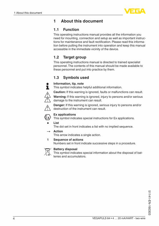
1.3 Symbols usedInformation, tip, noteThis symbol indicates helpful additional information.Caution: If this warning is ignored, faults or malfunctions can result.Warning: If this warning is ignored, injury to persons and/or serious damage to the instrument can result.Danger: If this warning is ignored, serious injury to persons and/or destruction of the instrument can result.
Ex applicationsThis symbol indicates special instructions for Ex applications.
• ListThe dot set in front indicates a list with no implied sequence.
→ ActionThis arrow indicates a single action.
1 Sequence of actionsNumbers set in front indicate successive steps in a procedure.
Battery disposalThis symbol indicates special information about the disposal of bat-teries and accumulators.
5
2 For your safety
VEGAPULS 64 • 4 … 20 mA/HART - two-wire
5114
1-EN
-160
303
2 For your safety
2.1 Authorised personnelAll operations described in this operating instructions manual must be carried out only by trained specialist personnel authorised by the plant operator.During work on and with the device the required personal protective equipment must always be worn.
2.2 Appropriate useVEGAPULS 64 is a sensor for continuous level measurement.Youcanfinddetailedinformationabouttheareaofapplicationinchapter "Product description".Operational reliability is ensured only if the instrument is properly usedaccordingtothespecificationsintheoperatinginstructionsmanual as well as possible supplementary instructions.
2.3 Warning about incorrect useInappropriate or incorrect use of the instrument can give rise to application-specifichazards,e.g.vesseloverfillordamagetosystemcomponents through incorrect mounting or adjustment. Also the pro-tectivecharacteristicsoftheinstrumentcanbeinfluenced.
2.4 General safety instructionsThis is a state-of-the-art instrument complying with all prevailing regulations and guidelines. The instrument must only be operated in a technicallyflawlessandreliablecondition.Theoperatorisresponsiblefor the trouble-free operation of the instrument.During the entire duration of use, the user is obliged to determine the compliance of the necessary occupational safety measures with the current valid rules and regulations and also take note of new regula-tions.The safety instructions in this operating instructions manual, the na-tional installation standards as well as the valid safety regulations and accident prevention rules must be observed by the user.For safety and warranty reasons, any invasive work on the device beyond that described in the operating instructions manual may be carried out only by personnel authorised by the manufacturer. Arbi-traryconversionsormodificationsareexplicitlyforbidden.The safety approval markings and safety tips on the device must also be observed.Depending on the instrument version, the emitting frequencies are in the C, K or W band range. The low emitting frequencies are far below the internationally approved limit values. When used correctly, the device poses no danger to health.

6
2 For your safety
VEGAPULS 64 • 4 … 20 mA/HART - two-wire
51141-EN-160303
2.5 CE conformityThedevicefulfillsthelegalrequirementsoftheapplicableECguide-lines.ByaffixingtheCEmarking,weconfirmsuccessfultestingoftheproduct.YoucanfindtheCECertificateofConformityinthedownloadsectionof our homepage.
2.6 NAMUR recommendationsNAMUR is the automation technology user association in the process industry in Germany. The published NAMUR recommendations are acceptedasthestandardinfieldinstrumentation.ThedevicefulfillstherequirementsofthefollowingNAMURrecom-mendations:
• NE 21 – Electromagnetic compatibility of equipment• NE 43 – Signal level for malfunction information from measuring
transducers• NE53–Compatibilityoffielddevicesanddisplay/adjustment
components• NE107–Self-monitoringanddiagnosisoffielddevicesFor further information see www.namur.de.
2.7 Radio license for EuropeThe instrument is approved according to EN 302372-1/2 V1.2.1 (2011-02) for use in closed vessels.For operation inside of closed vessels, the following conditions must befulfilled:
• The instrument must be permanently mounted on a closed vessel made of metal, reinforced concrete, or comparable attenuating materials.
• Flanges,processfittingsandmountingaccessoriesmustensurethe microwave impermeability of the vessel and not let the radar signal escape to the outside
• If necessary, existing viewing windows in the vessel must be coated with a microwave impermeable material (e.g. electrically conductive coating)
• Manholesandflangesonthevesselmustbeclosedandsealedtoavoid penetration of the radar signal
• The instrument should be preferably mounted on top of the vessel with antenna orientation downward
• The instrument must only be installed and maintained by appropri-atelyqualifiedstaff
2.8 Environmental instructionsProtection of the environment is one of our most important duties. That is why we have introduced an environment management system with the goal of continuously improving company environmental pro-tection.Theenvironmentmanagementsystemiscertifiedaccordingto DIN EN ISO 14001.

7
2 For your safety
VEGAPULS 64 • 4 … 20 mA/HART - two-wire
5114
1-EN
-160
303
Pleasehelpusfulfillthisobligationbyobservingtheenvironmentalinstructions in this manual:
• Chapter "Packaging, transport and storage"• Chapter "Disposal"
8
3 Product description
VEGAPULS 64 • 4 … 20 mA/HART - two-wire
51141-EN-160303
3 Product description
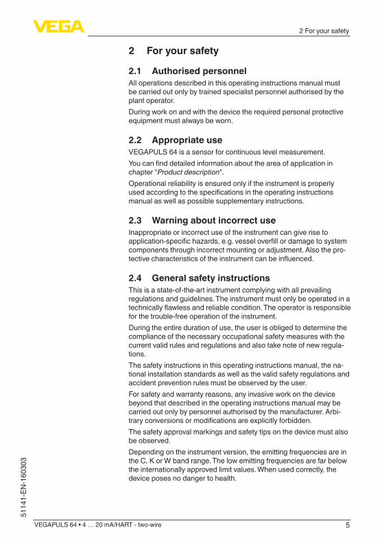
3.1 ConfigurationThetypelabelcontainsthemostimportantdataforidentificationanduse of the instrument:
21
12
11
10
9
56
4
3
78
Fig. 1: Layout of the type label (example)1 Instrument type2 Product code3 License label4 Power supply and signal output, electronics5 Protection rating6 Measuring range7 Process and ambient temperature, process pressure8 Material, wetted parts9 Serial number of the instrument10 Data-Matrix-Code for smartphone app11 Symbol of the device protection class12 Reminder to observe the instrument documentation
The type label contains the serial number of the instrument. With it youcanfindthefollowinginstrumentdataonourhomepage:
• Product code (HTML)• Delivery date (HTML)• Order-specificinstrumentfeatures(HTML)• Operating instructions and quick setup guide at the time of ship-
ment (PDF)• Order-specificsensordataforanelectronicsexchange(XML)• Testcertificate(PDF)-optionalGo to www.vega.com "VEGA Tools" and "Instrument search". Enter the serial number.Alternatively, you can access the data via your smartphone:
• Download the smartphone app "VEGA Tools" from the "Apple App Store" or the "Google Play Store"
• Scan the Data Matrix code on the type label of the instrument or• Enter the serial number manually in the app
This operating instructions manual applies to the following instrument versions:
Type label
Serial number - Instru-ment search
Scope of this operating instructions manual
9
3 Product description
VEGAPULS 64 • 4 … 20 mA/HART - two-wire
5114
1-EN
-160
303
• Hardware version from 1.0.0• Software version from 1.1.0
The scope of delivery encompasses:
• Radar sensor• Optional accessory• Documentation
– Quick setup guide VEGAPULS 64 – Instructions for optional instrument features – Ex-specific"Safety instructions" (with Ex versions) – Ifnecessary,furthercertificates
• DVD "Software", included therein – PACTware/DTM Collection – Driver software
Information:In this operating instructions manual, the optional instrument features are described. The respective scope of delivery results from the order specification.
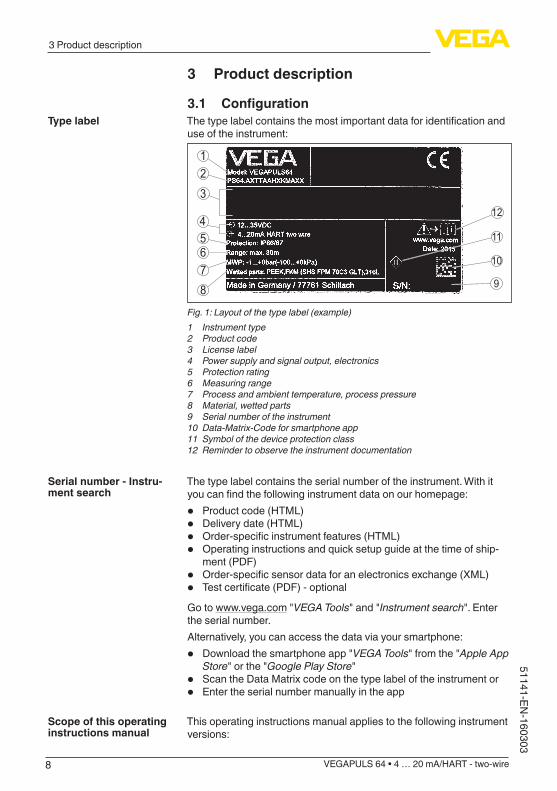
3.2 Principle of operationVEGAPULS 64 is a radar sensor for continuous level measurement of liquids.Specialadvantagesareofferedbysmallprocessfittingswithsmalltanks and the very good focussing with applications in large tanks. This is made possible by its functional principle, a distance measure-ment through frequency shifting with an especially small beam angle.Theinstrumentisavailablewithdifferentantennasystemsandacces-sories for virtually all applications and processes.
1 2 3
Fig. 2: Antenna systems VEGAPULS 641 Thread with integrated horn antenna2 Plastic horn antenna3 Flange with encapsulated antenna system
The instrument emits a continuous radar signal through its antenna. This signal is frequency modulated in the form of a sawtooth wave.
Scope of delivery
Application area
Functional principle
10
3 Product description
VEGAPULS 64 • 4 … 20 mA/HART - two-wire
51141-EN-160303
Theemittedsignalisreflectedbythemediumandreceivedbytheantenna as an echo.The frequency of the received signal always deviates from the actual emittingfrequency.Thefrequencydifferenceisproportionaltothedistanceandthustothefillingheight.Thisdifferenceiscalculatedviaspecialalgorithmsinthesensorelectronics.Thedeterminedfill-ing height is then converted into a corresponding output signal and outputted as the measured value.
3.3 Packaging, transport and storageYour instrument was protected by packaging during transport. Its capacity to handle normal loads during transport is assured by a test based on ISO 4180.The packaging of standard instruments consists of environment-friendly, recyclable cardboard. For special versions, PE foam or PE foil is also used. Dispose of the packaging material via specialised recycling companies.
Transport must be carried out in due consideration of the notes on the transport packaging. Nonobservance of these instructions can cause damage to the device.
The delivery must be checked for completeness and possible transit damage immediately at receipt. Ascertained transit damage or con-cealed defects must be appropriately dealt with.
Up to the time of installation, the packages must be left closed and stored according to the orientation and storage markings on the outside.Unless otherwise indicated, the packages must be stored only under the following conditions:
• Not in the open• Dry and dust free• Not exposed to corrosive media• Protected against solar radiation• Avoiding mechanical shock and vibration
• Storage and transport temperature see chapter "Supplement - Technical data - Ambient conditions"
• Relative humidity 20 … 85 %
3.4 Accessories and replacement partsDasAnzeige-undBedienmodulPLICSCOMdientzurMesswer-tanzeige,BedienungundDiagnose.EskannjederzeitindenSensoreingesetztundwiederentferntwerden.WeitereInformationenfindenSieinderBetriebsanleitung"Anzeige- und Bedienmodul PLICSCOM" (Document-ID 27835).
The interface adapter VEGACONNECT enables the connection of communication-capable instruments to the USB interface of a PC. For
Packaging
Transport
Transport inspection
Storage
Storage and transport temperature
PLICSCOM
VEGACONNECT
11
3 Product description
VEGAPULS 64 • 4 … 20 mA/HART - two-wire
5114
1-EN
-160
303
parameter adjustment of these instruments, the adjustment software PACTware with VEGA-DTM is required.Youcanfindfurtherinformationintheoperatinginstructions"Interface adapter VEGACONNECT" (Document-ID 32628).
The VEGADIS 81 is an external display and adjustment unit for VEGA plics® sensors.For sensors with double chamber housing the interface adapter "DISADAPT" is also required for VEGADIS 81.Youcanfindfurtherinformationintheoperatinginstructions"VE-GADIS 81" (Document-ID 43814).
The adapter "DISADAPT" is an accessory part for sensors with dou-ble chamber housings. It enables the connection of VEGADIS 81 to the sensor housing via an M12 x 1 plug.Youcanfindfurtherinformationinthesupplementaryinstructions"Adapter DISADAPT" (Document-ID 45250).
VEGADIS 82 is suitable for measured value indication and adjustment of sensors with HART protocol. It is looped into the 4 … 20 mA/HART signal cable.Youcanfindfurtherinformationintheoperatinginstructions"VE-GADIS 82" (Document-ID 45300).
PLICSMOBILE T61 is an external GSM/GPRS radio unit for transmis-sion of measured values and for remote parameter adjustment of plics® sensors. Adjustment is carried out via PACTware/DTM and the integrated USB connection.Youcanfindfurtherinformationinthesupplementaryinstructions"PLICSMOBILE T61" (Document-ID 37700).
DieSchutzhaubeschütztdasSensorgehäusevorVerschmutzungundstarkerErwärmungdurchSonneneinstrahlung.WeitereInformationenfindenSieinderZusatzanleitung"Schutzhaube" (Document-ID 34296).
Screwedflangesareavailableindifferentversionsaccordingtothefollowing standards: DIN 2501, EN 1092-1, BS 10, ASME B 16.5, JIS B 2210-1984, GOST 12821-80.Youcanfindadditionalinformationinthesupplementaryinstructionsmanual "Flanges according to DIN-EN-ASME-JIS".
For mounting the instrument with plastic horn antenna to a socket, twoflangeversionsareavailable:thecombicompressionflangeandtheadapterflangeYoucanfindadditionalinformationinchapter"Mounting" of this operating instruction.
A mounting strap is available for mounting the instrument with plastic horn antenna to the wall or ceiling.
VEGADIS 81
DISADAPT
VEGADIS 82
PLICSMOBILE T61
Schutzhaube
Flanges
Flanges with plastic horn antenna
Mounting strap with plas-tic horn antenna

12
3 Product description
VEGAPULS 64 • 4 … 20 mA/HART - two-wire
51141-EN-160303
Youcanfindadditionalinformationinchapter"Mounting" of this operating instruction.
Electronics module "VEGAPULS series 60" is a replacement part for radarsensorsofVEGAPULSseries60.Adifferentversionisavailablefor each type of signal output.Youcanfindfurtherinformationintheoperatinginstructions"Elec-tronics module VEGAPULS series 60" (Document-ID 36801).
Electronics module
13
4 Mounting
VEGAPULS 64 • 4 … 20 mA/HART - two-wire
5114
1-EN
-160
303
4 Mounting
4.1 General instructionsProtect your instrument against moisture ingress through the following measures:
• Use the recommended cable (see chapter "Connecting to power supply")
• Tighten the cable gland• Loop the connection cable downward in front of the cable gland
This applies particularly to:
• Outdoor mounting• Installations in areas where high humidity is expected (e.g. through
cleaning processes)• Installations on cooled or heated vessels
Make sure that all parts of the instrument exposed to the process are suitable for the existing process conditions.These are mainly:
• Active measuring component• Processfitting• Process seal
Process conditions are particularly:
• Process pressure• Process temperature• Chemical properties of the medium• AbrasionandmechanicalinfluencesYoucanfinddetailedinformationontheprocessconditionsinchapter"Technical data" as well as on the type label.
Metric threadsIn the case of instrument housings with metric thread, the cable glands are screwed in at the factory. They are sealed with plastic plugs as transport protection.You have to remove these plugs before electrical connection.
NPT threadIn the case of instrument housings with self-sealing NPT threads, it is not possible to have the cable entries screwed in at the factory. The free openings for the cable glands are therefore covered with red dust protection caps as transport protection. The dust protection caps do notprovidesufficientprotectionagainstmoisture.Prior to setup you have to replace these protective caps with ap-proved cable glands or close the openings with suitable blind plugs.
4.2 Mounting versions, plastic horn antennaThe optional mounting strap allows simple mounting of the instrument on a wall, ceiling or boom. Especially in the case of open vessels, this
Protection against mois-ture
Suitability for the process conditions
Cable glands
Mounting strap
14
4 Mounting
VEGAPULS 64 • 4 … 20 mA/HART - two-wire
51141-EN-160303
isasimpleandeffectivewaytoalignthesensortothesurfaceofthebulk solid material.The following versions are available:
• Length 300 mm• Length 170 mm
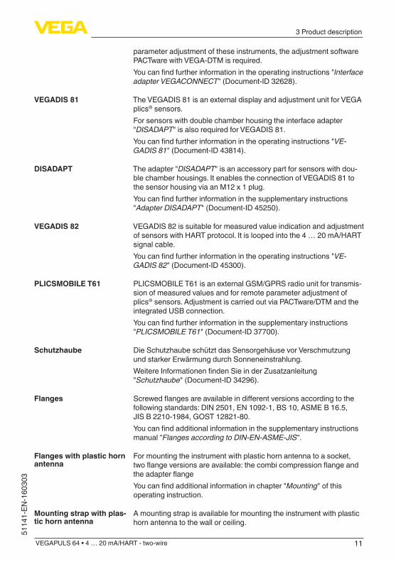
The instrument is normally mounted vertically with a bracket on the ceiling.This allows swivelling the sensor up to 180° for optimal orientation and rotating for optimal connection.
Fig. 3: Ceiling mounting via the mounting strap with length 300 mm
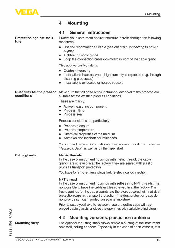
Fig. 4: Rotating with ceil mounting
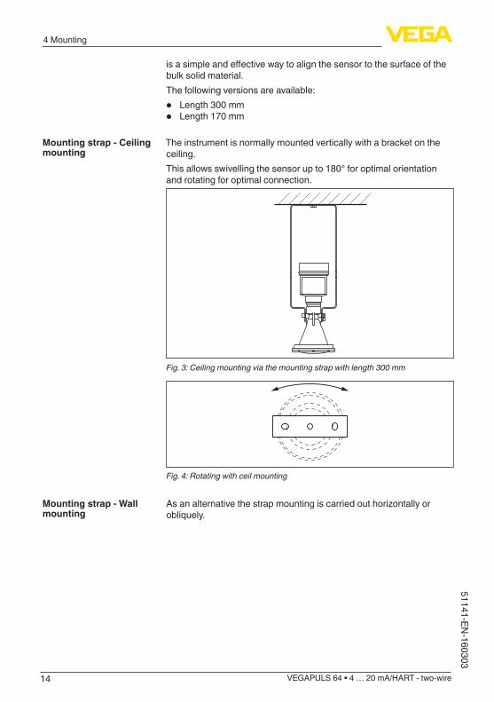
Asanalternativethestrapmountingiscarriedouthorizontallyorobliquely.
Mounting strap - Ceiling mounting
Mounting strap - Wall mounting
15
4 Mounting
VEGAPULS 64 • 4 … 20 mA/HART - two-wire
5114
1-EN
-160
303
> 200 mm(7.87")
Fig. 5: Wall mounting horizontally via the mounting strap with length 170 mm
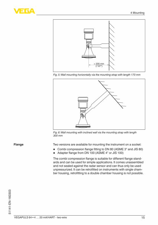
Fig. 6: Wall mounting with inclined wall via the mounting strap with length 300 mm
Two versions are available for mounting the instrument on a socket:
• CombicompressionflangefittingtoDN80(ASME3"andJIS80)• AdapterflangefromDN100(ASME4"orJIS100)Thecombicompressionflangeissuitablefordifferentflangestand-ards and can be used for simple applications. It comes unassembled and not sealed against the radar sensor and can thus only be used unpressurized.Itcanberetrofittedoninstrumentswithsinglecham-berhousing,retrofittingtoadoublechamberhousingisnotpossible.
Flange
16
4 Mounting
VEGAPULS 64 • 4 … 20 mA/HART - two-wire
51141-EN-160303
1
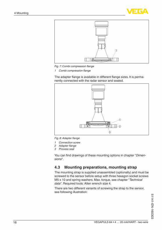
Fig. 7: Combi compression flange1 Combi compression flange
Theadapterflangeisavailableindifferentflangesizes.Itisperma-nently connected with the radar sensor and sealed.
3
1
2
Fig. 8: Adapter flange1 Connection screw2 Adapter flange3 Process seal
Youcanfinddrawingsofthesemountingoptionsinchapter"Dimen-sions".
4.3 Mounting preparations, mounting strapThe mounting strap is supplied unassembled (optionally) and must be screwed to the sensor before setup with three hexagon socket screws M5 x 10 and spring washers. Max. torque, see chapter "Technical data".Requiredtools:Allenwrenchsize4.Therearetwodifferentvariantsofscrewingthestraptothesensor,see following illustration:

17
4 Mounting
VEGAPULS 64 • 4 … 20 mA/HART - two-wire
5114
1-EN
-160
303
1 2
Fig. 9: Mounting strap for screwing to the sensor1 For angle of inclination in steps2 For angle of inclination, infinitely variable
Depending on the selected variant, the sensor can be rotated in the strap:
• Single chamber housing – Angle of inclination in three steps 0°, 90° and 180° – Angleofinclination180°,infinitelyvariable
• Double chamber housing – Angleofinclination90°,infinitelyvariable – Angle of inclination in two steps 0° and 90°
4.4 Mounting instructionsRadar sensors for level measurement emit electromagnetic waves. Thepolarizationisthedirectionoftheelectricalcomponentofthesewaves.Thepolarizationdirectionismarkedbyanoseonthehousing,seefollowing drawing:
1
Fig. 10: Position of the polarisation1 Nose for marking the direction of polarisation
Information:Whenthehousingisrotated,thedirectionofpolarizationchangesandhencetheinfluenceofthefalseechoonthemeasuredvalue.Please keep this in mind when mounting or making changes later.
When mounting the sensor, keep a distance of at least 200 mm (7.874 in) from the vessel wall. If the sensor is installed in the center of dished or round vessel tops, multiple echoes can arise. However,
Polarisation
Installation position
18
4 Mounting
VEGAPULS 64 • 4 … 20 mA/HART - two-wire
51141-EN-160303
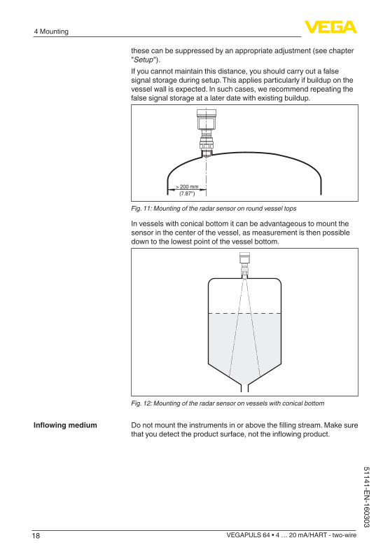
these can be suppressed by an appropriate adjustment (see chapter "Setup").If you cannot maintain this distance, you should carry out a false signal storage during setup. This applies particularly if buildup on the vessel wall is expected. In such cases, we recommend repeating the false signal storage at a later date with existing buildup.
> 200 mm(7.87")
Fig. 11: Mounting of the radar sensor on round vessel tops
In vessels with conical bottom it can be advantageous to mount the sensor in the center of the vessel, as measurement is then possible down to the lowest point of the vessel bottom.
Fig. 12: Mounting of the radar sensor on vessels with conical bottom
Donotmounttheinstrumentsinorabovethefillingstream.Makesurethatyoudetecttheproductsurface,nottheinflowingproduct.
Inflowingmedium
19
4 Mounting
VEGAPULS 64 • 4 … 20 mA/HART - two-wire
5114
1-EN
-160
303
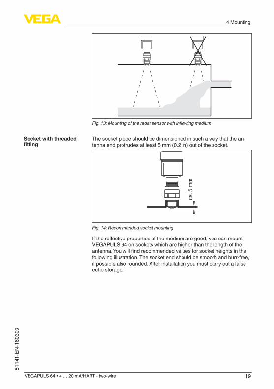
Fig. 13: Mounting of the radar sensor with inflowing medium
The socket piece should be dimensioned in such a way that the an-tenna end protrudes at least 5 mm (0.2 in) out of the socket.
ca. 5
mm
Fig. 14: Recommended socket mounting
Ifthereflectivepropertiesofthemediumaregood,youcanmountVEGAPULS 64 on sockets which are higher than the length of the antenna.Youwillfindrecommendedvaluesforsocketheightsinthefollowing illustration. The socket end should be smooth and burr-free, if possible also rounded. After installation you must carry out a false echo storage.
Socket with threaded fitting
20
4 Mounting
VEGAPULS 64 • 4 … 20 mA/HART - two-wire
51141-EN-160303
d
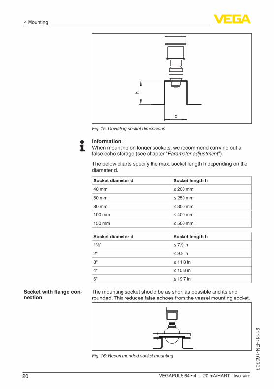
hFig. 15: Deviating socket dimensions
Information:When mounting on longer sockets, we recommend carrying out a false echo storage (see chapter "Parameter adjustment").
The below charts specify the max. socket length h depending on the diameter d.
Socket diameter d Socket length h
40 mm ≤200mm
50 mm ≤250mm
80 mm ≤300mm
100 mm ≤400mm
150 mm ≤500mm
Socket diameter d Socket length h
1½" ≤7.9in
2" ≤9.9in
3" ≤11.8in
4" ≤15.8in
6" ≤19.7in
The mounting socket should be as short as possible and its end rounded. This reduces false echoes from the vessel mounting socket.
Fig. 16: Recommended socket mounting
Socketwithflangecon-nection
21
4 Mounting
VEGAPULS 64 • 4 … 20 mA/HART - two-wire
5114
1-EN
-160
303
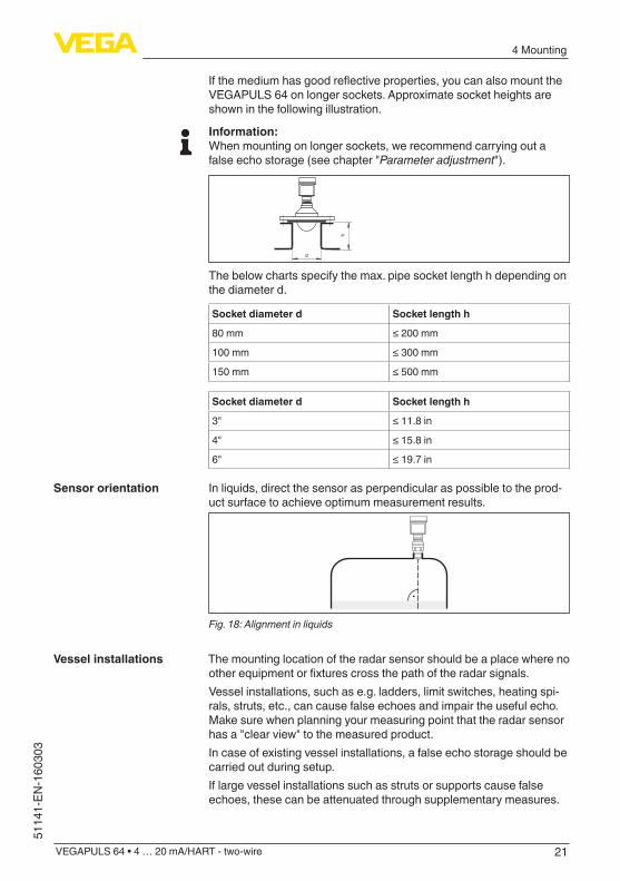
Ifthemediumhasgoodreflectiveproperties,youcanalsomounttheVEGAPULS 64 on longer sockets. Approximate socket heights are shown in the following illustration.
Information:When mounting on longer sockets, we recommend carrying out a false echo storage (see chapter "Parameter adjustment").
d
h
The below charts specify the max. pipe socket length h depending on the diameter d.
Socket diameter d Socket length h
80 mm ≤200mm
100 mm ≤300mm
150 mm ≤500mm
Socket diameter d Socket length h
3" ≤11.8in
4" ≤15.8in
6" ≤19.7in
In liquids, direct the sensor as perpendicular as possible to the prod-uct surface to achieve optimum measurement results.
Fig. 18: Alignment in liquids
The mounting location of the radar sensor should be a place where no otherequipmentorfixturescrossthepathoftheradarsignals.Vessel installations, such as e.g. ladders, limit switches, heating spi-rals, struts, etc., can cause false echoes and impair the useful echo. Make sure when planning your measuring point that the radar sensor has a "clear view" to the measured product.In case of existing vessel installations, a false echo storage should be carried out during setup.If large vessel installations such as struts or supports cause false echoes, these can be attenuated through supplementary measures.
Sensor orientation
Vessel installations
22
4 Mounting
VEGAPULS 64 • 4 … 20 mA/HART - two-wire
51141-EN-160303
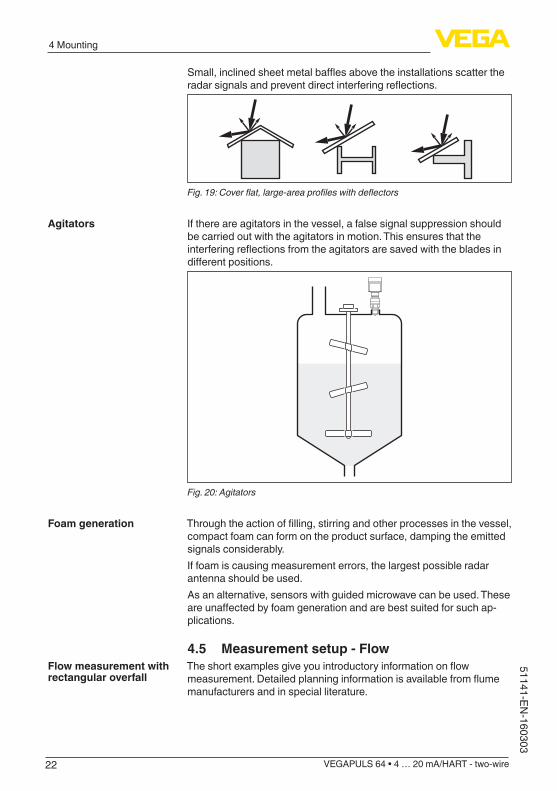
Small,inclinedsheetmetalbafflesabovetheinstallationsscattertheradarsignalsandpreventdirectinterferingreflections.
Fig. 19: Cover flat, large-area profiles with deflectors
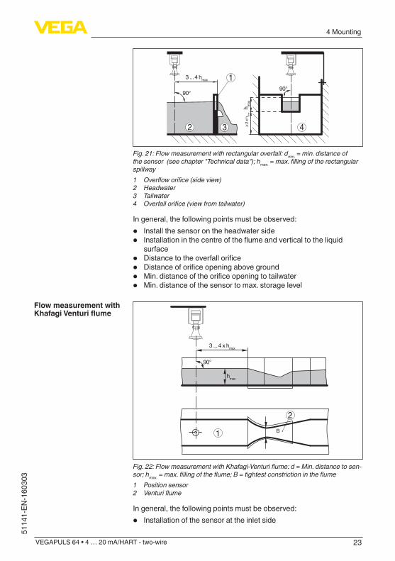
If there are agitators in the vessel, a false signal suppression should be carried out with the agitators in motion. This ensures that the interferingreflectionsfromtheagitatorsaresavedwiththebladesindifferentpositions.
Fig. 20: Agitators
Throughtheactionoffilling,stirringandotherprocessesinthevessel,compact foam can form on the product surface, damping the emitted signals considerably.If foam is causing measurement errors, the largest possible radar antenna should be used.As an alternative, sensors with guided microwave can be used. These areunaffectedbyfoamgenerationandarebestsuitedforsuchap-plications.
4.5 Measurement setup - FlowTheshortexamplesgiveyouintroductoryinformationonflowmeasurement.Detailedplanninginformationisavailablefromflumemanufacturers and in special literature.
Agitators
Foam generation
Flow measurement with rectangular overfall
23
4 Mounting
VEGAPULS 64 • 4 … 20 mA/HART - two-wire
5114
1-EN
-160
303
h max
≥ 2
x hm
ax
90°
4
3 ... 4 hmax
90°
2 3
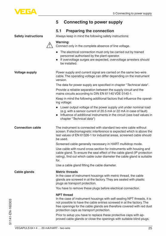
1
Fig. 21: Flow measurement with rectangular overfall: dmin. = min. distance of the sensor (see chapter "Technical data"); hmax. = max. filling of the rectangular spillway1 Overflow orifice (side view)2 Headwater3 Tailwater4 Overfall orifice (view from tailwater)
In general, the following points must be observed:
• Install the sensor on the headwater side• Installationinthecentreoftheflumeandverticaltotheliquid
surface• Distancetotheoverfallorifice• Distanceoforificeopeningaboveground• Min.distanceoftheorificeopeningtotailwater• Min. distance of the sensor to max. storage level
2
3 ... 4 x hmax
90°
hmax
1 B
Fig. 22: Flow measurement with Khafagi-Venturi flume: d = Min. distance to sen-sor; hmax. = max. filling of the flume; B = tightest constriction in the flume1 Position sensor2 Venturi flume
In general, the following points must be observed:
• Installation of the sensor at the inlet side
Flow measurement with KhafagiVenturiflume

24
4 Mounting
VEGAPULS 64 • 4 … 20 mA/HART - two-wire
51141-EN-160303
• Installationinthecentreoftheflumeandverticaltotheliquidsurface
• DistancetotheVenturiflume• Min. distance of the sensor to max. storage level
25
5 Connecting to power supply
VEGAPULS 64 • 4 … 20 mA/HART - two-wire
5114
1-EN
-160
303
5 Connecting to power supply
5.1 Preparing the connectionAlways keep in mind the following safety instructions:
Warning:Connect only in the complete absence of line voltage.
• The electrical connection must only be carried out by trained personnel authorised by the plant operator.
• If overvoltage surges are expected, overvoltage arresters should be installed.
Power supply and current signal are carried on the same two-wire cable.Theoperatingvoltagecandifferdependingontheinstrumentversion.Thedataforpowersupplyarespecifiedinchapter"Technical data".Provide a reliable separation between the supply circuit and the mains circuits according to DIN EN 61140 VDE 0140-1.Keepinmindthefollowingadditionalfactorsthatinfluencetheoperat-ing voltage:
• Lower output voltage of the power supply unit under nominal load (e.g. with a sensor current of 20.5 mA or 22 mA in case of fault)
• Influenceofadditionalinstrumentsinthecircuit(seeloadvaluesinchapter "Technical data")
The instrument is connected with standard two-wire cable without screen. If electromagnetic interference is expected which is above the test values of EN 61326-1 for industrial areas, screened cable should be used.Screened cable generally necessary in HART multidrop mode.Use cable with round cross section for instruments with housing and cablegland.Toensurethesealeffectofthecablegland(IPprotectionrating),findoutwhichcableouterdiameterthecableglandissuitablefor.Useacableglandfittingthecablediameter.
Metric threadsIn the case of instrument housings with metric thread, the cable glands are screwed in at the factory. They are sealed with plastic plugs as transport protection.You have to remove these plugs before electrical connection.
NPT threadIn the case of instrument housings with self-sealing NPT threads, it is not possible to have the cable entries screwed in at the factory. The free openings for the cable glands are therefore covered with red dust protection caps as transport protection.Prior to setup you have to replace these protective caps with ap-proved cable glands or close the openings with suitable blind plugs.
Safety instructions
Voltage supply
Connection cable
Cable glands
26
5 Connecting to power supply
VEGAPULS 64 • 4 … 20 mA/HART - two-wire
51141-EN-160303
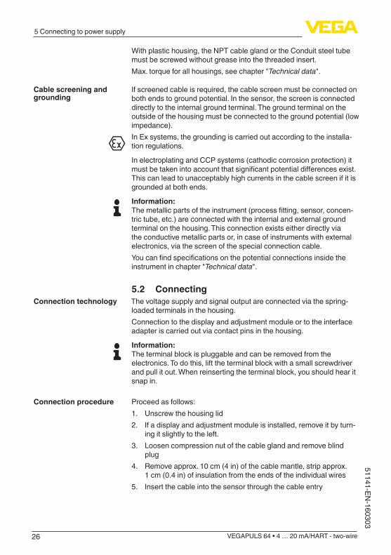
With plastic housing, the NPT cable gland or the Conduit steel tube must be screwed without grease into the threaded insert.Max. torque for all housings, see chapter "Technical data".
If screened cable is required, the cable screen must be connected on both ends to ground potential. In the sensor, the screen is connected directly to the internal ground terminal. The ground terminal on the outside of the housing must be connected to the ground potential (low impedance).In Ex systems, the grounding is carried out according to the installa-tion regulations.
In electroplating and CCP systems (cathodic corrosion protection) it mustbetakenintoaccountthatsignificantpotentialdifferencesexist.This can lead to unacceptably high currents in the cable screen if it is grounded at both ends.
Information:Themetallicpartsoftheinstrument(processfitting,sensor,concen-tric tube, etc.) are connected with the internal and external ground terminal on the housing. This connection exists either directly via the conductive metallic parts or, in case of instruments with external electronics, via the screen of the special connection cable.Youcanfindspecificationsonthepotentialconnectionsinsidetheinstrument in chapter "Technical data".
5.2 ConnectingThe voltage supply and signal output are connected via the spring-loaded terminals in the housing.Connection to the display and adjustment module or to the interface adapter is carried out via contact pins in the housing.
Information:The terminal block is pluggable and can be removed from the electronics. To do this, lift the terminal block with a small screwdriver and pull it out. When reinserting the terminal block, you should hear it snap in.
Proceed as follows:1. Unscrew the housing lid2. If a display and adjustment module is installed, remove it by turn-
ing it slightly to the left.3. Loosen compression nut of the cable gland and remove blind
plug4. Remove approx. 10 cm (4 in) of the cable mantle, strip approx.
1 cm (0.4 in) of insulation from the ends of the individual wires5. Insert the cable into the sensor through the cable entry
Cable screening and grounding
Connection technology
Connection procedure

27
5 Connecting to power supply
VEGAPULS 64 • 4 … 20 mA/HART - two-wire
5114
1-EN
-160
303
Fig. 23: Connection steps 5 and 6 - Single chamber housing
Fig. 24: Connection steps 5 and 6 - Double chamber housing
6. Insert the wire ends into the terminals according to the wiring plan
Information:Solidcoresaswellasflexiblecoreswithwireendsleevesareinsert-eddirectlyintotheterminalopenings.Incaseofflexiblecoreswithoutend sleeves, press the terminal from above with a small screwdriver, the terminal opening is then free. When the screwdriver is released, the terminal closes again.Youcanfindfurtherinformationonthemax.wirecross-sectionunder"Technical data - Electromechanical data"
7. Check the hold of the wires in the terminals by lightly pulling on them
8. Connect the screen to the internal ground terminal, connect the external ground terminal to potential equalisation

28
5 Connecting to power supply
VEGAPULS 64 • 4 … 20 mA/HART - two-wire
51141-EN-160303
9. Tighten the compression nut of the cable entry gland. The seal ring must completely encircle the cable
10. Reinsert the display and adjustment module, if one was installed11. Screw the housing lid back onTheelectricalconnectionisfinished.
5.3 Wiring plan, single chamber housingThe following illustration applies to the non-Ex as well as to the Ex-ia version.
51 2+( ) (-) 6 7 8
4...20mA
2
3
41
Fig. 25: Electronics and terminal compartment, single chamber housing1 Voltage supply, signal output2 For display and adjustment module or interface adapter3 For external display and adjustment unit4 Ground terminal for connection of the cable screen
5.4 Wiring plan, double chamber housingThe following illustrations apply to the non-Ex as well as to the Ex-ia version.
5 6 7 8
4...20mA
1 2+( ) (-)
2
1 1
Fig. 26: Electronics compartment, double chamber housing1 Internal connection to the terminal compartment2 For display and adjustment module or interface adapter
Electronics and terminal compartment
Electronics compartment

29
5 Connecting to power supply
VEGAPULS 64 • 4 … 20 mA/HART - two-wire
5114
1-EN
-160
303
51 2+( ) (-) 6 7 8
4...20mA Display
2
3
41
Fig. 27: Terminal compartment, double chamber housing1 Voltage supply, signal output2 For display and adjustment module or interface adapter3 For external display and adjustment unit4 Ground terminal for connection of the cable screen
Information:Parallel use of an external display and adjustment unit and a display and adjustment module in the terminal compartment is not supported.
5.5 Double chamber housing Ex d
5 6 7 8
4...20mA
2
1 2+( ) (-)
11
Fig. 28: Electronics compartment, double chamber housing Ex d1 Internal connection to the terminal compartment2 For display and adjustment module or interface adapter
Terminal compartment
Electronics compartment
30
5 Connecting to power supply
VEGAPULS 64 • 4 … 20 mA/HART - two-wire
51141-EN-160303
51 2+( ) (-) 6 7 8
4...20mA
2
3
41
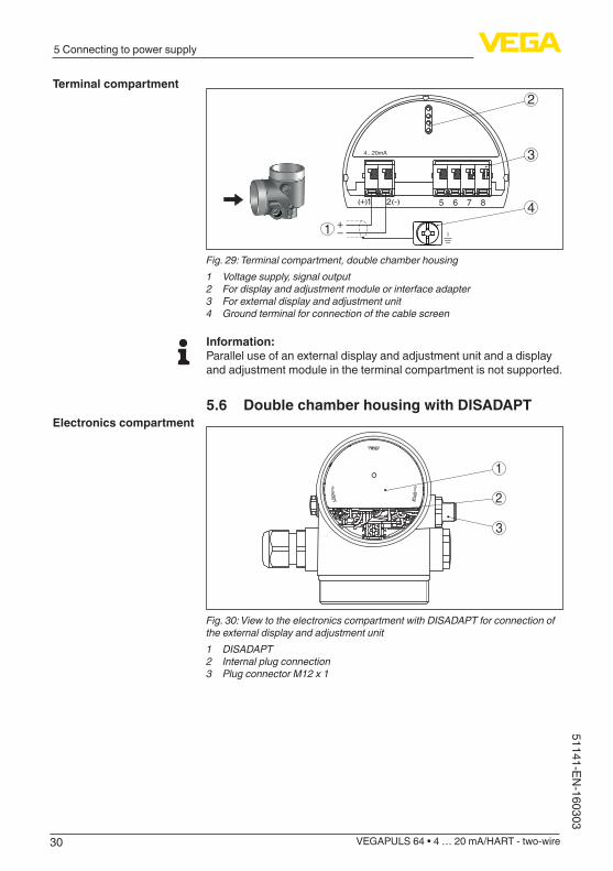
Fig. 29: Terminal compartment, double chamber housing1 Voltage supply, signal output2 For display and adjustment module or interface adapter3 For external display and adjustment unit4 Ground terminal for connection of the cable screen
Information:Parallel use of an external display and adjustment unit and a display and adjustment module in the terminal compartment is not supported.
5.6 Double chamber housing with DISADAPT
3
1
2
Fig. 30: View to the electronics compartment with DISADAPT for connection of the external display and adjustment unit1 DISADAPT2 Internal plug connection3 Plug connector M12 x 1
Terminal compartment
Electronics compartment
31
5 Connecting to power supply
VEGAPULS 64 • 4 … 20 mA/HART - two-wire
5114
1-EN
-160
303
34
1 2
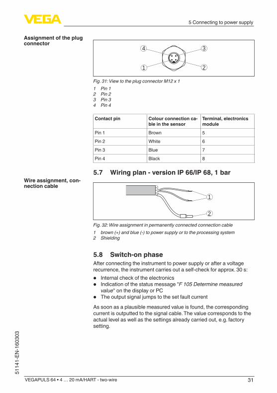
Fig. 31: View to the plug connector M12 x 11 Pin 12 Pin 23 Pin 34 Pin 4
Contact pin Colour connection ca-ble in the sensor
Terminal, electronics module
Pin 1 Brown 5
Pin 2 White 6
Pin 3 Blue 7
Pin 4 Black 8
5.7 Wiring plan - version IP 66/IP 68, 1 bar
1
2
Fig. 32: Wire assignment in permanently connected connection cable1 brown (+) and blue (-) to power supply or to the processing system2 Shielding
5.8 Switch-on phaseAfter connecting the instrument to power supply or after a voltage recurrence, the instrument carries out a self-check for approx. 30 s:
• Internal check of the electronics• Indication of the status message "F 105 Determine measured
value" on the display or PC• The output signal jumps to the set fault current
As soon as a plausible measured value is found, the corresponding current is outputted to the signal cable. The value corresponds to the actual level as well as the settings already carried out, e.g. factory setting.
Assignment of the plug connector
Wire assignment, con-nection cable

32
6 Set up with the display and adjustment module
VEGAPULS 64 • 4 … 20 mA/HART - two-wire
51141-EN-160303
6 Set up with the display and adjustment module
6.1 Insert display and adjustment moduleThe display and adjustment module can be inserted into the sensor andremovedagainatanytime.Youcanchooseanyoneoffourdiffer-ent positions - each displaced by 90°. It is not necessary to interrupt the power supply.Proceed as follows:1. Unscrew the housing lid2. Place the display and adjustment module on the electronics in the
desired position and turn it to the right until it snaps in.3. Screw housing lid with inspection window tightly back onDisassembly is carried out in reverse order.The display and adjustment module is powered by the sensor, an ad-ditional connection is not necessary.
Fig. 33: Installing the display and adjustment module in the electronics compart-ment of the single chamber housing

33
6 Set up with the display and adjustment module
VEGAPULS 64 • 4 … 20 mA/HART - two-wire
5114
1-EN
-160
303
1 2
Fig. 34: Installing the display and adjustment module in the double chamber housing1 In the electronics compartment2 In the terminal compartment
Note:Ifyouintendtoretrofittheinstrumentwithadisplayandadjustmentmodule for continuous measured value indication, a higher lid with an inspection glass is required.
6.2 Adjustment system
1
2
Fig. 35: Display and adjustment elements1 LC display2 Adjustment keys
• [OK] key:Key functions
34
6 Set up with the display and adjustment module
VEGAPULS 64 • 4 … 20 mA/HART - two-wire
51141-EN-160303
– Move to the menu overview – Confirmselectedmenu – Edit parameter – Save value
• [->] key: – Presentation, change measured value – Select list entry – Select menu items in the quick setup menu – Select editing position
• [+] key: – Change value of the parameter
• [ESC] key: – Interrupt input – Jump to next higher menu
The instrument is operated via the four keys of the display and adjust-ment module. The individual menu items are shown on the LC display. Youcanfindthefunctionsoftheindividualkeysinthepreviousillustration.
When the [+] and [->] keys are pressed quickly, the edited value, i.e. the cursor, moves by one position. When the keys are pressed longer than 1 s, the cursor moves continuously.When the [OK] and [ESC] keys are pressed simultaneously for more than 5 s, the display returns to the main menu. The menu language is then switched over to "English".Approx. 60 minutes after the last pressing of a key, an automatic reset tomeasuredvalueindicationistriggered.Anyvaluesnotconfirmedwith [OK] will not be saved.
6.3 Measured value indication - Selection national language
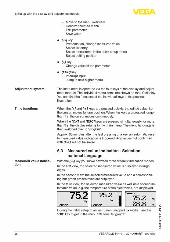
With the [->]keyyoumovebetweenthreedifferentindicationmodes.Inthefirstview,theselectedmeasuredvalueisdisplayedinlargedigits.In the second view, the selected measured value and a correspond-ing bar graph presentation are displayed.In the third view, the selected measured value as well as a second se-lectable value, e.g. the temperature of the electronics, are displayed.
During the initial setup of an instrument shipped Ex works, use the "OK" key to get to the menu "National language".
Adjustment system
Time functions
Measured value indica-tion
35
6 Set up with the display and adjustment module
VEGAPULS 64 • 4 … 20 mA/HART - two-wire
5114
1-EN
-160
303
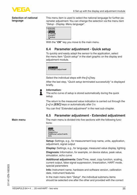
This menu item is used to select the national language for further pa-rameter adjustment. You can change the selection via the menu item "Setup - Display, Menu language".
With the "OK" key you move to the main menu.
6.4 Parameter adjustment - Quick setupTo quickly and easily adapt the sensor to the application, select the menu item "Quick setup" in the start graphic on the display and adjustment module.
Select the individual steps with the [->] key.After the last step, "Quick setup terminated successfully" is displayed briefly.
Information:The echo curve of setup is stored automatically during the quick setup.
The return to the measured value indication is carried out through the [->] or [ESC] keys or automatically after 3 sYoucanfind"Extended adjustment" in the next sub-chapter.
6.5 Parameter adjustment - Extended adjustmentThemainmenuisdividedintofivesectionswiththefollowingfunc-tions:
Setup: Settings, e.g., for measurement loop name, units, application, adjustment, signal outputDisplay: Settings, e.g., for language, measured value display, lightingDiagnosis: Information, for example, on device status, peak value, simulation, echo curveAdditional adjustments: Date/Time, reset, copy function, scaling, currentoutput,falsesignalsuppression,linearization,HARTmode,special parametersInfo: Instrument name, hardware and software version, calibration date, instrument featuresIn the main menu item "Setup", the individual submenu items should be selected one after the other and provided with the correct
Selection of national language
Main menu

36
6 Set up with the display and adjustment module
VEGAPULS 64 • 4 … 20 mA/HART - two-wire
51141-EN-160303
parameters to ensure optimum adjustment of the measurement. The procedure is described in the following.
Here you can assign a suitable measurement loop name. Push the "OK" key to start the editing. With the "+" key you change the sign and with the "->" key you jump to the next position.You can enter names with max. 19 characters. The character set comprises:
• CapitallettersfromA…Z• Numbers from 0 … 9• Special characters + - / _ blanks
In this menu item you select the distance unit and the temperature unit.
For the distance units you can choose between m, in and ft and for the temperature units °C, °F and K.
This menu item allows you to adapt the sensor to the measuring conditions.
MediumThe following options are available:
ApplicationThe following options are available:
The following features form the basis of the applications:
- Storage tank:• Setup: large-volumed, upright cylindrical, spherical• Productspeed:slowfillingandemptying
Setup - Measurement loop name
Setup - Units
Setup - Application
37
6 Set up with the display and adjustment module
VEGAPULS 64 • 4 … 20 mA/HART - two-wire
5114
1-EN
-160
303
• Process/measurement conditions: – Condensation – Smooth product surface – High requirements on measurement accuracy
• Properties, sensor: – Low sensitivity to sporadic false echoes – Stable and reliable measured values through averaging – High accuracy – Short reaction time of the sensor not required
- Storage tank with product circulation:• Setup: large-volumed, upright cylindrical, spherical• Productspeed:slowfillingandemptying• Installations: small laterally mounted or large top mounted stirrer• Process/measurement conditions:
– Relatively smooth product surface – High requirements on measurement accuracy – Condensation – Slight foam generation – Overfillingpossible
• Properties, sensor: – Low sensitivity to sporadic false echoes – Stable and reliable measured values through averaging – High accuracy, because not set for max. speed – False signal suppression recommended
- Storage tank on ships (Cargo Tank):• Productspeed:slowfillingandemptying• Vessel:
– Installations in the bottom section (bracers, heating spirals) – High sockets 200 … 500 mm, also with large diameters
• Process/measurement conditions: – Condensation, buildup by movement – Max. requirement on measurement accuracy from 95 %
• Properties, sensor: – Low sensitivity to sporadic false echoes – Stable and reliable measured values through averaging – High accuracy – False signal suppression required
- Stirrer vessel (reactor):• Setup:allvesselsizespossible• Product speed:
– Fasttoslowfillingpossible – Vesselisfilledandemptiedveryoften
• Vessel: – Socket available – Large agitator blades of metal – Vortex breakers, heating spirals
• Process/measurement conditions: – Condensation, buildup by movement – Strong spout generation – Very agitated surface, foam generation
38
6 Set up with the display and adjustment module
VEGAPULS 64 • 4 … 20 mA/HART - two-wire
51141-EN-160303
• Properties, sensor: – Higher measurement speed through less averaging – Sporadic false echoes are suppressed
- Dosing vessel:• Setup:allvesselsizespossible• Product speed:
– Fastfillingandemptying – Vesselisfilledandemptiedveryoften
• Vessel: tight installation situation• Process/measurement conditions:
– Condensation, buildup on the antenna – Foam generation
• Properties, sensor: – Measurementspeedoptimizedbyvirtuallynoaveraging – Sporadic false echoes are suppressed – False signal suppression recommended
- Plastic tank:• Vessel:
– Instrumentfixmountedorbuiltin – Measurement through the vessel top, if appropriate to the
application – With empty vessel, the measurement can go through the bot-
tom• Process/measurement conditions:
– Condensation on the plastic ceiling – In outdoor facilities, water and snow on vessel top possible
• Properties, sensor: – False signals outside the vessel are not taken into consideration – False signal suppression recommended
- Transportable plastic tank:• Vessel:
– Materialandthicknessdifferent – Measurement through the vessel top
• Process/measurement conditions: – Measured value jump with vessel change
• Properties, sensor: – Quickadaptationtochangingreflectionconditionsduetoves-
sel change – False signal suppression required
- Open water (gauge measurement):• Rate of level change: slow level change• Process/measurement conditions:
– Large distance from sensor to water surface – Extreme damping of output signal due to wave generation – Ice and condensation on the antenna possible – Spiders and insects build nests in the antennas – Floating material and animals sporadically appear on water
surface• Properties, sensor:
39
6 Set up with the display and adjustment module
VEGAPULS 64 • 4 … 20 mA/HART - two-wire
5114
1-EN
-160
303
– Stable and reliable measured values through frequent averag-ing
– Insensitive in the close range
-Openflume(flowmeasurement):• Rate of level change: slow level change• Process/measurement conditions:
– Ice and condensation on the antenna possible – Spiders and insects build nests in the antennas – Smooth water surface – Exact measurement result required – Distance to the water surface normally relatively large
• Properties, sensor: – Stable and reliable measured values through frequent averag-
ing – Insensitive in the close range
- Rain water spillover (weir):• Rate of level change: slow level change• Process/measurement conditions:
– Ice and condensation on the antenna possible – Spiders and insects build nests in the antennas – Turbulent water surface – Sensorfloodingpossible
• Properties, sensor: – Stable and reliable measured values through frequent averag-
ing – Insensitive in the close range
- Demonstration:• Adjustment for all applications which are not typically level meas-
urement – Instrument demonstration – Object recognition/monitoring (additional settings required)
• Properties, sensor: – Sensor accepts all measured value changes within the measur-
ing range immediately – High sensitivity to interference, because virtually no averaging
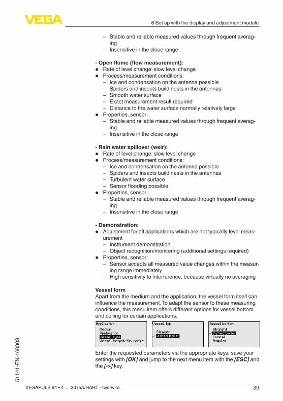
Vessel formApart from the medium and the application, the vessel form itself can influencethemeasurement.Toadaptthesensortothesemeasuringconditions,thismenuitemoffersdifferentoptionsforvesselbottomand ceiling for certain applications.
Enter the requested parameters via the appropriate keys, save your settings with [OK] and jump to the next menu item with the [ESC] and the [->] key.

40
6 Set up with the display and adjustment module
VEGAPULS 64 • 4 … 20 mA/HART - two-wire
51141-EN-160303
Vessel height/Measuring rangeThrough this selection the operating range of the sensor is adapted to the vessel height, which considerably increases measurement certaintyunderdifferentbasicconditions.The min. adjustment must be carried out independently of this.
Enter the requested parameters via the appropriate keys, save your settings with [OK] and jump to the next menu item with the [ESC] and the [->] key.
Caution:Ifliquidswithdifferentdielectricconstantsseparateinthevessel,forexample through condensation, the radar sensor can detect under certain circumstances only the medium with the higher dielectric constant. Keep in mind that layer interfaces can cause faulty meas-urements.If you want to measure the total height of both liquids reliably, please contact our service department or use an instrument specially de-signed for interface measurement.
Since the radar sensor is a distance measuring instrument, the distance from the sensor to the product surface is measured. To indicate the actual level, an allocation of the measured distance to the percentage height must be carried out.To perform the adjustment, enter the distance with full and empty ves-sel, see the following example:
100%
0%
0,5
m(1
9.68
")5
m(1
96.9
")
2
1
3
Fig. 36: Parameter adjustment example min./max. adjustment1 Min. level = max. measuring distance2 Max. level = min. measuring distance3 Reference plane
Setup - Adjustment
41
6 Set up with the display and adjustment module
VEGAPULS 64 • 4 … 20 mA/HART - two-wire
5114
1-EN
-160
303
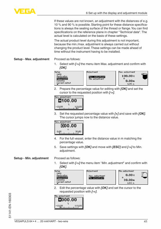
If these values are not known, an adjustment with the distances of e.g. 10%and90%ispossible.Startingpointforthesedistancespecifica-tionsisalwaysthesealingsurfaceofthethreadorflange.Youcanfindspecificationsonthereferenceplaneinchapter"Technical data". The actual level is calculated on the basis of these settings.The actual product level during this adjustment is not important, because the min./max. adjustment is always carried out without changing the product level. These settings can be made ahead of time without the instrument having to be installed.
Proceed as follows:1. Select with [->]themenuitemMax.adjustmentandconfirmwith
[OK].
2. Prepare the percentage value for editing with [OK] and set the cursor to the requested position with [->].
3. Set the requested percentage value with [+] and save with [OK]. The cursor jumps now to the distance value.
4. For the full vessel, enter the distance value in m matching the percentage value.
5. Save settings with [OK] and move with [ESC] and [->] to Min. adjustment.
Proceed as follows:1. Select with [->] the menu item "Min. adjustment"andconfirmwith
[OK].
2. Edit the percentage value with [OK] and set the cursor to the requested position with [->].
Setup - Max. adjustment
Setup - Min. adjustment

42
6 Set up with the display and adjustment module
VEGAPULS 64 • 4 … 20 mA/HART - two-wire
51141-EN-160303
3. Set the requested percentage value with [+] and save with [OK]. The cursor jumps now to the distance value.
4. Enter the suitable distance value in m for the empty vessel (e.g. distance from the sensor to the vessel bottom) corresponding to the percentage value.
Todampprocess-dependentmeasuredvaluefluctuations,setanintegration time of 0 … 999 s in this menu item.
The default setting is a damping of 0 s.
In the menu item "Current output mode" you determine the output characteristics and reaction of the current output in case of failure.
The default setting is output characteristics 4 … 20 mA, failure mode < 3.6 mA.
In the menu item "Current output Min./Max.", you determine the reac-tion of the current output during operation.
The default setting is min. current 3.8 mA and max. current 20.5 mA.
In the menu item "Lock/unlock adjustment", you can protect the sen-sorparametersagainstunauthorizedorinadvertentmodification.ThePIN is activated/deactivated permanently.With active PIN, only the following adjustment functions are possible without entering a PIN:
• Select menu items and show data• Read data from the sensor into the display and adjustment mod-
ule.
Setup - Damping
Setup - Current output mode
Setup - Current output Min./Max.
Lock/unlock setup - Ad-justment
43
6 Set up with the display and adjustment module
VEGAPULS 64 • 4 … 20 mA/HART - two-wire
5114
1-EN
-160
303
Caution:With active PIN, adjustment via PACTware/DTM as well as other systems is also blocked.
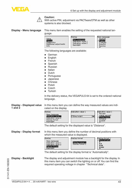
This menu item enables the setting of the requested national lan-guage.
The following languages are available:
• German• English• French• Spanish• Russian• Italian• Dutch• Portuguese• Japanese• Chinese• Polish• Czech• Turkish
In the delivery status, the VEGAPULS 64 is set to the ordered national language.
Inthismenuitemyoucandefinethewaymeasuredvaluesareindi-cated on the display.
The default setting for the displayed value is "Distance".
Inthismenuitemyoudefinethenumberofdecimalpositionswithwhich the measured value is displayed.
The default setting for the display format is "Automatically".
The display and adjustment module has a backlight for the display. In thismenuitemyoucanswitchthelightingonoroff.Youcanfindtherequired operating voltage in chapter "Technical data".
Display - Menu language
Display - Displayed value 1 and 2
Display - Display format
Display - Backlight
44
6 Set up with the display and adjustment module
VEGAPULS 64 • 4 … 20 mA/HART - two-wire
51141-EN-160303
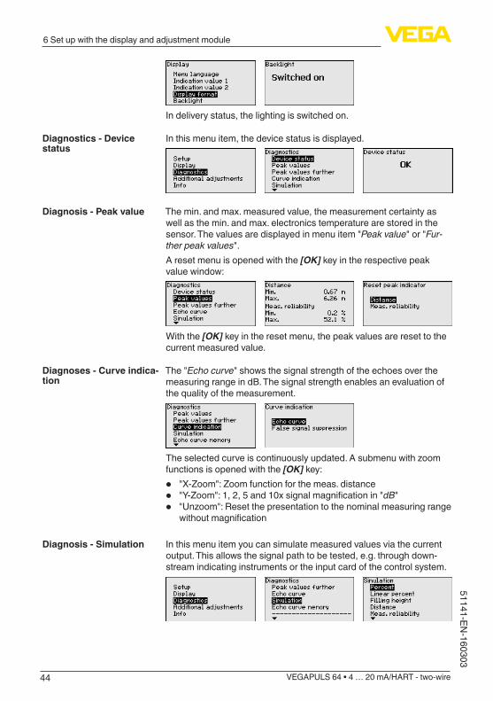
In delivery status, the lighting is switched on.
In this menu item, the device status is displayed.
The min. and max. measured value, the measurement certainty as well as the min. and max. electronics temperature are stored in the sensor. The values are displayed in menu item "Peak value" or "Fur-ther peak values".A reset menu is opened with the [OK] key in the respective peak value window:
With the [OK] key in the reset menu, the peak values are reset to the current measured value.
The "Echo curve" shows the signal strength of the echoes over the measuring range in dB. The signal strength enables an evaluation of the quality of the measurement.
Theselectedcurveiscontinuouslyupdated.Asubmenuwithzoomfunctions is opened with the [OK] key:
• "X-Zoom":Zoomfunctionforthemeas.distance• "Y-Zoom":1,2,5and10xsignalmagnificationin"dB"• "Unzoom":Resetthepresentationtothenominalmeasuringrange
withoutmagnification
In this menu item you can simulate measured values via the current output. This allows the signal path to be tested, e.g. through down-stream indicating instruments or the input card of the control system.
Diagnostics - Device status
Diagnosis - Peak value
Diagnoses - Curve indica-tion
Diagnosis - Simulation
45
6 Set up with the display and adjustment module
VEGAPULS 64 • 4 … 20 mA/HART - two-wire
5114
1-EN
-160
303
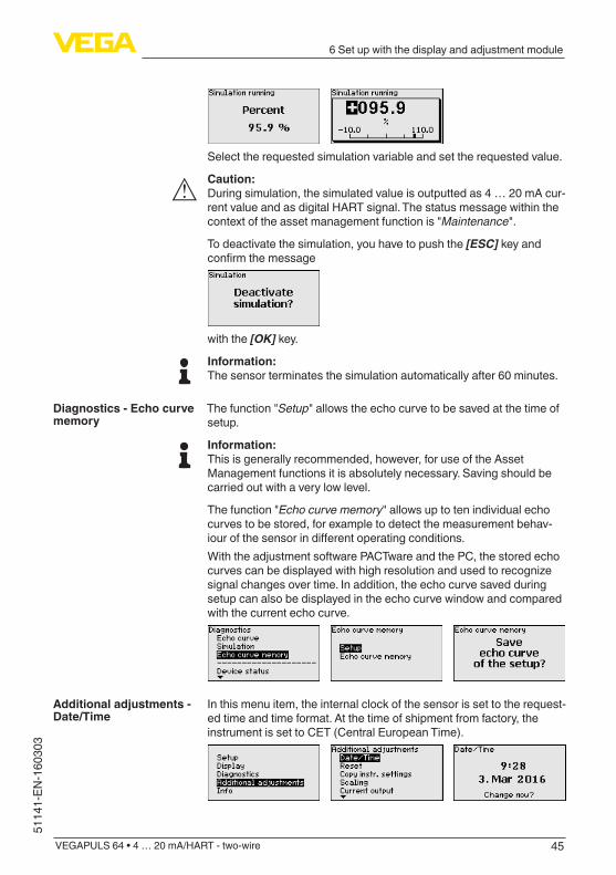
Select the requested simulation variable and set the requested value.
Caution:During simulation, the simulated value is outputted as 4 … 20 mA cur-rent value and as digital HART signal. The status message within the context of the asset management function is "Maintenance".
To deactivate the simulation, you have to push the [ESC] key and confirmthemessage
with the [OK] key.
Information:The sensor terminates the simulation automatically after 60 minutes.
The function "Setup" allows the echo curve to be saved at the time of setup.
Information:This is generally recommended, however, for use of the Asset Management functions it is absolutely necessary. Saving should be carried out with a very low level.
The function "Echo curve memory" allows up to ten individual echo curves to be stored, for example to detect the measurement behav-iourofthesensorindifferentoperatingconditions.With the adjustment software PACTware and the PC, the stored echo curvescanbedisplayedwithhighresolutionandusedtorecognizesignal changes over time. In addition, the echo curve saved during setup can also be displayed in the echo curve window and compared with the current echo curve.
In this menu item, the internal clock of the sensor is set to the request-ed time and time format. At the time of shipment from factory, the instrument is set to CET (Central European Time).
Diagnostics - Echo curve memory
Additional adjustments - Date/Time
46
6 Set up with the display and adjustment module
VEGAPULS 64 • 4 … 20 mA/HART - two-wire
51141-EN-160303
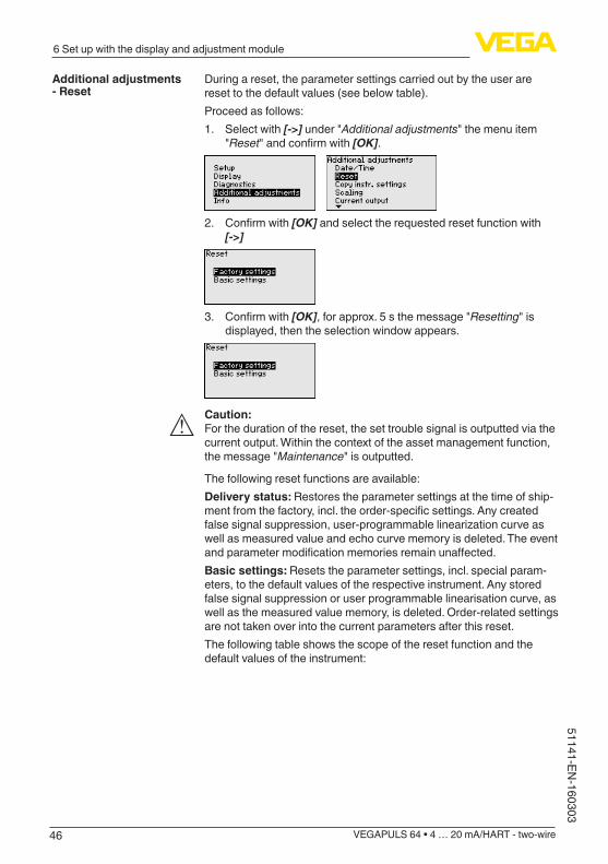
During a reset, the parameter settings carried out by the user are reset to the default values (see below table).Proceed as follows:1. Select with [->] under "Additional adjustments" the menu item
"Reset"andconfirmwith[OK].
2. Confirmwith[OK] and select the requested reset function with [->]
3. Confirmwith[OK], for approx. 5 s the message "Resetting" is displayed, then the selection window appears.
Caution:For the duration of the reset, the set trouble signal is outputted via the current output. Within the context of the asset management function, the message "Maintenance" is outputted.
The following reset functions are available:Delivery status: Restores the parameter settings at the time of ship-mentfromthefactory,incl.theorder-specificsettings.Anycreatedfalsesignalsuppression,user-programmablelinearizationcurveaswell as measured value and echo curve memory is deleted. The event andparametermodificationmemoriesremainunaffected.Basic settings: Resets the parameter settings, incl. special param-eters, to the default values of the respective instrument. Any stored false signal suppression or user programmable linearisation curve, as well as the measured value memory, is deleted. Order-related settings are not taken over into the current parameters after this reset.The following table shows the scope of the reset function and the default values of the instrument:
Additional adjustments - Reset

47
6 Set up with the display and adjustment module
VEGAPULS 64 • 4 … 20 mA/HART - two-wire
5114
1-EN
-160
303
Menu Menu item Default value
Setup Measurement loop name
Sensor
Units Distance in mTemperature in °C
Application Medium: Water solutionApplication: Storage tankVessel top: Dished formVessel bottom: Dished formVessel height/Measuring range: 30 m
Min. adjustment 30 m
Max. adjustment 0,000 m(d)
Damping 0.0 s
Current output mode
Output characteristics: 4 … 20 mAFailure mode: < 3.6 mA ▼
Current output Min./Max.
Min. current: 3.8 mAMax. current: 20.5 mA
Display Displayed value 1 Filling height
Displayed value 2 Electronics temperature
Backlight Switched on
Additional adjust-ments
Date/Time Time format: 24 h
Scalingsize Volumel
Scaling format 100.00 lin %, 100 l0.00 lin %, 0 l
Current output 1 and2size
Lin %
Current output 1 and 2 adjustment
100.00 %, 100 l0.00 %, 0 l
Linearization Linear
HART mode HART address: 0Loop current mode: Analogue cur-rent output
The instrument settings are copied with this function. The following functions are available:Read from sensor: Read data from sensor and store into the display and adjustment moduleWrite into sensor: Store data from the display and adjustment mod-ule back into the sensorThe following data or settings for adjustment of the display and ad-justment module are saved:
• All data of the menu "Setup" and "Display"
Additional adjustments - Copy instrument settings
48
6 Set up with the display and adjustment module
VEGAPULS 64 • 4 … 20 mA/HART - two-wire
51141-EN-160303
• The menu items "Reset, Date/Time" in the menu "Additional set-tings"
• Theuser-programmablelinearizationcurve
The copied data are permanently saved in an EEPROM memory in the display and adjustment module and remain there even in case of power failure. From there, they can be written into one or more sen-sors or kept as backup for a possible electronics exchange.
Note:Before the data are saved in the sensor, a safety check is carried out to determine if the data match the sensor. In the process the sensor type of the source data as well as the target sensor are displayed. If the data do not match, a fault message is outputted or the function is blocked. The data are saved only after release.
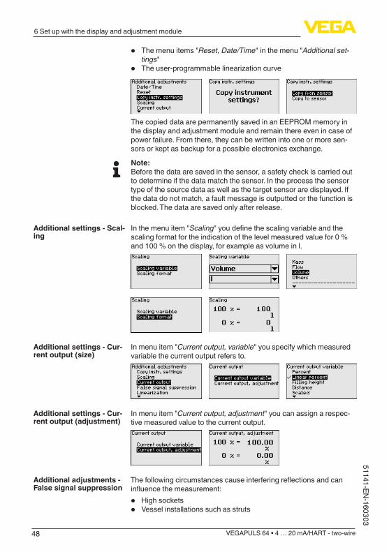
In the menu item "Scaling"youdefinethescalingvariableandthescaling format for the indication of the level measured value for 0 % and 100 % on the display, for example as volume in l.
In menu item "Current output, variable" you specify which measured variable the current output refers to.
In menu item "Current output, adjustment" you can assign a respec-tive measured value to the current output.
Thefollowingcircumstancescauseinterferingreflectionsandcaninfluencethemeasurement:
• High sockets• Vessel installations such as struts
Additional settings - Scal-ing
Additional settings - Cur-rent output (size)
Additional settings - Cur-rent output (adjustment)
Additional adjustments - False signal suppression
49
6 Set up with the display and adjustment module
VEGAPULS 64 • 4 … 20 mA/HART - two-wire
5114
1-EN
-160
303
• Agitators• Buildup or welded joints on vessel walls
Note:A false signal suppression detects, marks and saves these false signals so that they are no longer taken into account in the level measurement.
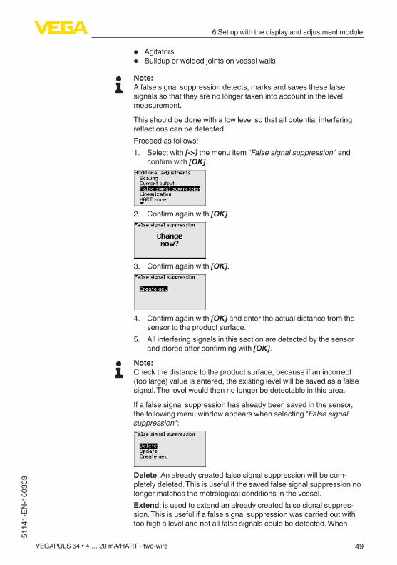
This should be done with a low level so that all potential interfering reflectionscanbedetected.Proceed as follows:1. Select with [->] the menu item "False signal suppression" and
confirmwith[OK].
2. Confirmagainwith[OK].
3. Confirmagainwith[OK].
4. Confirmagainwith[OK] and enter the actual distance from the sensor to the product surface.
5. All interfering signals in this section are detected by the sensor andstoredafterconfirmingwith[OK].
Note:Check the distance to the product surface, because if an incorrect (too large) value is entered, the existing level will be saved as a false signal. The level would then no longer be detectable in this area.
If a false signal suppression has already been saved in the sensor, the following menu window appears when selecting "False signal suppression":
Delete: An already created false signal suppression will be com-pletely deleted. This is useful if the saved false signal suppression no longer matches the metrological conditions in the vessel.Extend: is used to extend an already created false signal suppres-sion. This is useful if a false signal suppression was carried out with too high a level and not all false signals could be detected. When
50
6 Set up with the display and adjustment module
VEGAPULS 64 • 4 … 20 mA/HART - two-wire
51141-EN-160303
selecting "Extend", the distance to the product surface of the created false signal suppression is displayed. This value can now be changed and the false signal suppression can be extended to this range.
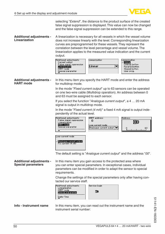
Alinearizationisnecessaryforallvesselsinwhichthevesselvolumedoesnotincreaselinearlywiththelevel.Correspondinglinearizationcurves are preprogrammed for these vessels. They represent the correlation between the level percentage and vessel volume. The linearizationappliestothemeasuredvalueindicationandthecurrentoutput.
In this menu item you specify the HART mode and enter the address for multidrop mode.In the mode "Fixed current output" up to 63 sensors can be operated on one two-wire cable (Multidrop operation). An address between 0 and 63 must be assigned to each sensor.If you select the function "Analogue current output", a 4 … 20 mA signal is output in multidrop mode.In the mode "Fixed current (4 mA)"afixed4mAsignalisoutputinde-pendently of the actual level.
The default setting is "Analogue current output" and the address "00".
In this menu item you gain access to the protected area where you can enter special parameters. In exceptional cases, individual parameterscanbemodifiedinordertoadaptthesensortospecialrequirements.Change the settings of the special parameters only after having con-tactedourservicestaff.
In this menu item, you can read out the instrument name and the instrument serial number:
Additional adjustments - Linearization
Additional adjustments - HART mode
Additional adjustments - Special parameters
Info - Instrument name
51
6 Set up with the display and adjustment module
VEGAPULS 64 • 4 … 20 mA/HART - two-wire
5114
1-EN
-160
303
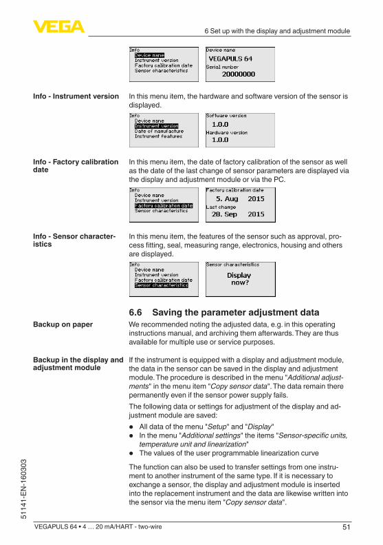
In this menu item, the hardware and software version of the sensor is displayed.
In this menu item, the date of factory calibration of the sensor as well as the date of the last change of sensor parameters are displayed via the display and adjustment module or via the PC.
In this menu item, the features of the sensor such as approval, pro-cessfitting,seal,measuringrange,electronics,housingandothersare displayed.
6.6 Saving the parameter adjustment dataWe recommended noting the adjusted data, e.g. in this operating instructions manual, and archiving them afterwards. They are thus available for multiple use or service purposes.
If the instrument is equipped with a display and adjustment module, the data in the sensor can be saved in the display and adjustment module. The procedure is described in the menu "Additional adjust-ments" in the menu item "Copy sensor data". The data remain there permanently even if the sensor power supply fails.The following data or settings for adjustment of the display and ad-justment module are saved:
• All data of the menu "Setup" and "Display"• In the menu "Additional settings" the items "Sensor-specific units,
temperature unit and linearization"• ThevaluesoftheuserprogrammablelinearizationcurveThe function can also be used to transfer settings from one instru-ment to another instrument of the same type. If it is necessary to exchange a sensor, the display and adjustment module is inserted into the replacement instrument and the data are likewise written into the sensor via the menu item "Copy sensor data".
Info - Instrument version
Info - Factory calibration date
Info - Sensor character-istics
Backup on paper
Backup in the display and adjustment module
52
7 Setup with PACTware
VEGAPULS 64 • 4 … 20 mA/HART - two-wire
51141-EN-160303
7 Setup with PACTware
7.1 Connect the PC
3
1
2
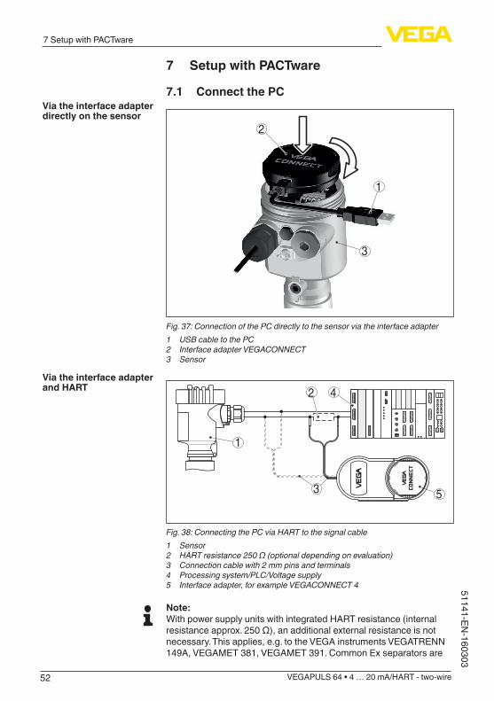
Fig. 37: Connection of the PC directly to the sensor via the interface adapter1 USB cable to the PC2 Interface adapter VEGACONNECT3 Sensor
1
5
2 4
3 OPEN
TWIST
USB
LOCK
Fig. 38: Connecting the PC via HART to the signal cable1 Sensor2 HART resistance 250 Ω (optional depending on evaluation)3 Connection cable with 2 mm pins and terminals4 Processing system/PLC/Voltage supply5 Interface adapter, for example VEGACONNECT 4
Note:With power supply units with integrated HART resistance (internal resistanceapprox.250Ω),anadditionalexternalresistanceisnotnecessary. This applies, e.g. to the VEGA instruments VEGATRENN 149A, VEGAMET 381, VEGAMET 391. Common Ex separators are
Via the interface adapter directly on the sensor
Via the interface adapter and HART
53
7 Setup with PACTware
VEGAPULS 64 • 4 … 20 mA/HART - two-wire
5114
1-EN
-160
303
alsousuallyequippedwithasufficientcurrentlimitationresistance.Insuch cases, the interface converter can be connected parallel to the 4 … 20 mA cable (dashed line in the previous illustration).
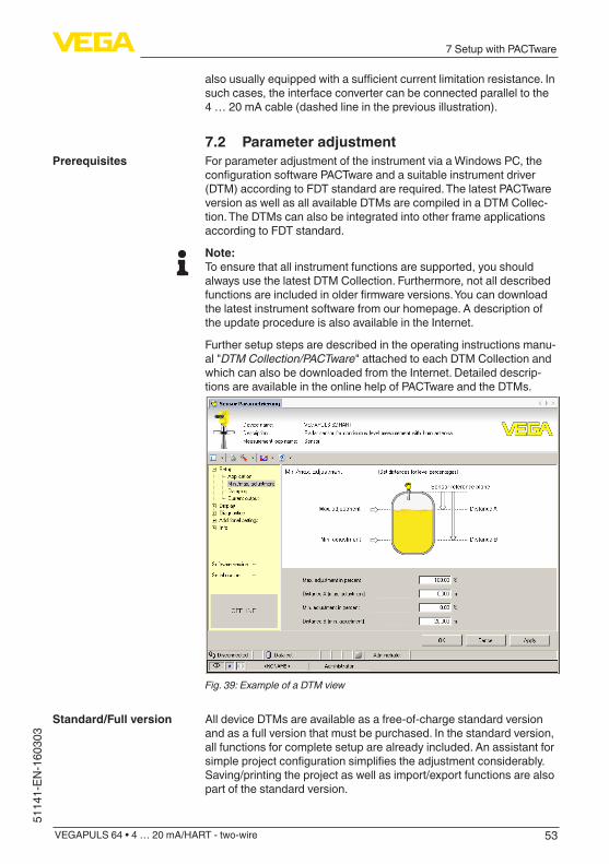
7.2 Parameter adjustmentFor parameter adjustment of the instrument via a Windows PC, the configurationsoftwarePACTwareandasuitableinstrumentdriver(DTM) according to FDT standard are required. The latest PACTware version as well as all available DTMs are compiled in a DTM Collec-tion. The DTMs can also be integrated into other frame applications according to FDT standard.
Note:To ensure that all instrument functions are supported, you should always use the latest DTM Collection. Furthermore, not all described functionsareincludedinolderfirmwareversions.Youcandownloadthe latest instrument software from our homepage. A description of the update procedure is also available in the Internet.
Further setup steps are described in the operating instructions manu-al "DTM Collection/PACTware" attached to each DTM Collection and which can also be downloaded from the Internet. Detailed descrip-tions are available in the online help of PACTware and the DTMs.
Fig. 39: Example of a DTM view
All device DTMs are available as a free-of-charge standard version and as a full version that must be purchased. In the standard version, all functions for complete setup are already included. An assistant for simpleprojectconfigurationsimplifiestheadjustmentconsiderably.Saving/printing the project as well as import/export functions are also part of the standard version.
Prerequisites
Standard/Full version
54
7 Setup with PACTware
VEGAPULS 64 • 4 … 20 mA/HART - two-wire
51141-EN-160303
In the full version there is also an extended print function for complete project documentation as well as a save function for measured value and echo curves. In addition, there is a tank calculation program as well as a multiviewer for display and analysis of the saved measured value and echo curves.The standard version is available as a download under www.vega.com/downloads and "Software". The full version is avail-able on CD from the agency serving you.
7.3 Saving the parameter adjustment dataWe recommend documenting or saving the parameter adjustment data via PACTware. That way the data are available for multiple use or service purposes.
55
8 Set up with other systems
VEGAPULS 64 • 4 … 20 mA/HART - two-wire
5114
1-EN
-160
303
8 Set up with other systems
8.1 DD adjustment programsDevice descriptions as Enhanced Device Description (EDD) are available for DD adjustment programs such as, for example, AMS™ and PDM.Thefilescanbedownloadedatwww.vega.com/downloads under "Software".
8.2 Field Communicator 375, 475Device descriptions for the instrument are available as EDD for pa-rameter adjustment with the Field Communicator 375 or 475.For the integration of the EDD in the Field Communicator 375 or 475, the software "Easy Upgrade Utility" is required which is available from the manufacturer. This software is updated via the Internet and new EDDs are automatically taken over into the device catalogue of this software after they are released by the manufacturer. They can then be transferred to a Field Communicator.
56
9 Diagnosis, asset management and service
VEGAPULS 64 • 4 … 20 mA/HART - two-wire
51141-EN-160303
9 Diagnosis, asset management and service
9.1 MaintenanceIf the instrument is used correctly, no maintenance is required in normal operation.Insomeapplications,buildupontheantennasystemcaninfluencethe measuring result. Depending on the sensor and application, take measures to avoid heavy soiling of the antenna system. If necessary, clean the antenna system in certain intervals.
9.2 Measured value and event memoryThe instrument has several memories which are available for diagnostic purposes. The data remain there even in case of voltage interruption.
Up to 100,000 measured values can be stored in the sensor in a ring memory. Each entry contains date/time as well as the respective measured value. Storable values are for example:
• Distance• Filling height• Percentage value• Lin. percent• Scaled• Current value• Meas. certainty• Electronics temperature
When the instrument is shipped, the measured value memory is active and stores distance, measurement certainty and electronics temperature every 3 minutes.The requested values and recording conditions are set via a PC with PACTware/DTM or the control system with EDD. Data are thus read out and also reset.
Up to 500 events are automatically stored with a time stamp in the sensor (non-deletable). Each entry contains date/time, event type, event description and value. Event types are for example:
• Modificationofaparameter• Switch-onandswitch-offtimes• Status messages (according to NE 107)• Error messages (according to NE 107)
The data are read out via a PC with PACTware/DTM or the control system with EDD.
The echo curves are stored with date and time and the corresponding echo data. The memory is divided into two sections:Echo curve of the setup: This is used as reference echo curve for the measurement conditions during setup. Changes in the measure-ment conditions during operation or buildup on the sensor can thus berecognized.Theechocurveofthesetupisstoredvia:
Measured value memory
Event memory
Echo curve memory

57
9 Diagnosis, asset management and service
VEGAPULS 64 • 4 … 20 mA/HART - two-wire
5114
1-EN
-160
303
• PC with PACTware/DTM • Control system with EDD • Display and adjustment module
Further echo curves: Up to 10 echo curves can be stored in a ring bufferinthismemorysection.Furtherechocurvesarestoredvia:
• PC with PACTware/DTM • Control system with EDD
9.3 Asset Management functionThe instrument features self-monitoring and diagnostics according to NE 107 and VDI/VDE 2650. In addition to the status messages in the following tables, detailed error messages are available under menu item "Diagnostics" via the display and adjustment module, PACTware/DTM and EDD.
The status messages are divided into the following categories:
• Failure• Function check• Outofspecification• Maintenance requirement
and explained by pictographs:
41 2 3Fig. 40: Pictographs of the status messages1 Failure - red2 Out of specification - yellow3 Function check - orange4 Maintenance - blue
Failure: Due to a malfunction in the instrument, a failure message is outputted.This status message is always active. It cannot be deactivated by the user.Function check: The instrument is in operation, the measured value is temporarily invalid (for example during simulation).This status message is inactive by default. It can be activated by the user via PACTware/DTM or EDD.Outofspecification: The measured value is unstable because the instrumentspecificationisexceeded(e.g.electronicstemperature).This status message is inactive by default. It can be activated by the user via PACTware/DTM or EDD.Maintenance:Duetoexternalinfluences,theinstrumentfunctionislimited.Themeasurementisaffected,butthemeasuredvalueis
Status messages

58
9 Diagnosis, asset management and service
VEGAPULS 64 • 4 … 20 mA/HART - two-wire
51141-EN-160303
still valid. Plan in maintenance for the instrument because a failure is expected in the near future (e.g. due to buildup).This status message is inactive by default. It can be activated by the user via PACTware/DTM or EDD.
The following table shows the error codes in the status message "Failure"andgivesinformationonthereasonandrectification.Keepin mind that some information is only valid with four-wire instruments.
CodeText message
Cause Rectification DevSpec State in CMD 48
F013no measured value avail-able
– Sensor does not detect an echo during opera-tion
– Antenna system dirty or defective
– Check or correct instal-lation and/or parameter adjustment
– Clean or exchange process component or antenna
Bit 0 of Byte 0…5
F017Adjustment span too small
– Adjustment not within specification
– Change adjustment according to the limit values(differencebetween min. and max. ≥10mm)
Bit 1 of Byte 0…5
F025Errorinthelinearizationtable
– Index markers are not continuously rising, for example illogical value pairs
– Checklinearizationtable – Delete table/Create new
Bit 2 of Byte 0…5
F036No operable software
– Failed or interrupted software update
– Repeat software update – Check electronics
version – Exchanging the elec-
tronics – Send instrument for
repair
Bit 3 of Byte 0…5
F040Error in the electronics
– Hardware defect – Exchanging the elec-tronics
– Send instrument for repair
Bit 4 of Byte 0…5
F080General software error
– General software error – Disconnect operating voltagebriefly
Bit 5 of Byte 0…5
F105Determine measured value
– The instrument is still in the start phase, the measured value could not yet be determined
– Wait for the end of the switch-on phase
– Duration depending on the version and param-eter adjustment up to approximately 3 min.
Bit 6 of Byte 0…5
F113Communication error
– EMC interference – Transmission error with
the external communica-tion with 4-wire power supply unit
– RemoveEMCinfluences – Exchange 4-wire power
supply unit or electron-ics
Bit 12 of Byte 0…5
Failure

59
9 Diagnosis, asset management and service
VEGAPULS 64 • 4 … 20 mA/HART - two-wire
5114
1-EN
-160
303
CodeText message
Cause Rectification DevSpec State in CMD 48
F125Impermissible electronics temperature
– Temperature of the electronics in the non-specifiedrange
– Check ambient tem-perature
– Isolate electronics – Use instrument with
higher temperature range
Bit 7 of Byte 0…5
F260Error in the calibration
– Error in the calibration carried out in the factory
– Error in the EEPROM
– Exchanging the elec-tronics
– Send instrument for repair
Bit 8 of Byte 0…5
F261Error in the instrument set-tings
– Error during setup – False signal suppression
faulty – Error when carrying out
a reset
– Repeat setup – Carry out a reset
Bit 9 of Byte 0…5
F264Installation/Setup error
– Adjustment not within the vessel height/meas-uring range
– Max. measuring range of the instrument not sufficient
– Check or correct instal-lation and/or parameter adjustment
– Use an instrument with bigger measuring range
Bit 10 of Byte 0…5
F265Measurement function dis-turbed
– Sensor no longer carries out a measurement
– Operating voltage too low
– Check operating voltage – Carry out a reset – Disconnect operating voltagebriefly
Bit 11 of Byte 0…5
The following table shows the error codes and text messages in the status message "Function check" and provides information on causes as well as corrective measures.
CodeText message
Cause Rectification DevSpec State in CMD 48
C700Simulation active
– A simulation is active – Finish simulation – Wait for the automatic
end after 60 mins.
"Simulation Active" in "StandardizedStatus0"
The following table shows the error codes and text messages in the status message "Out of specification" and provides information on causes as well as corrective measures.
CodeText message
Cause Rectification DevSpec State in CMD 48
S600Impermissible electronics temperature
– Temperature of the electronics in the non-specifiedrange
– Check ambient tem-perature
– Isolate electronics – Use instrument with
higher temperature range
Bit 8 of Byte 14…24
Function check
Outofspecification
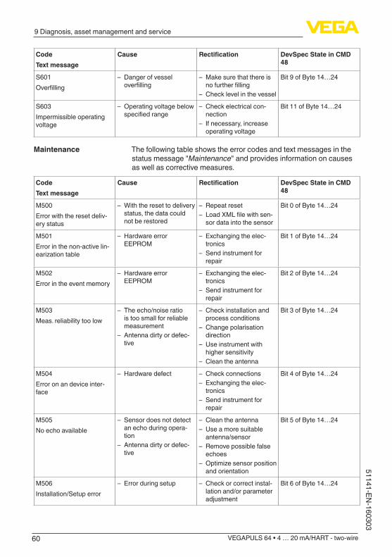
60
9 Diagnosis, asset management and service
VEGAPULS 64 • 4 … 20 mA/HART - two-wire
51141-EN-160303
CodeText message
Cause Rectification DevSpec State in CMD 48
S601Overfilling
– Danger of vessel overfilling
– Make sure that there is nofurtherfilling
– Check level in the vessel
Bit 9 of Byte 14…24
S603Impermissible operating voltage
– Operating voltage below specifiedrange
– Check electrical con-nection
– If necessary, increase operating voltage
Bit 11 of Byte 14…24
The following table shows the error codes and text messages in the status message "Maintenance" and provides information on causes as well as corrective measures.
CodeText message
Cause Rectification DevSpec State in CMD 48
M500Error with the reset deliv-ery status
– With the reset to delivery status, the data could not be restored
– Repeat reset – LoadXMLfilewithsen-
sor data into the sensor
Bit 0 of Byte 14…24
M501Error in the non-active lin-earizationtable
– Hardware error EEPROM
– Exchanging the elec-tronics
– Send instrument for repair
Bit 1 of Byte 14…24
M502Error in the event memory
– Hardware error EEPROM
– Exchanging the elec-tronics
– Send instrument for repair
Bit 2 of Byte 14…24
M503Meas. reliability too low
– The echo/noise ratio is too small for reliable measurement
– Antenna dirty or defec-tive
– Check installation and process conditions
– Change polarisation direction
– Use instrument with higher sensitivity
– Clean the antenna
Bit 3 of Byte 14…24
M504Error on an device inter-face
– Hardware defect – Check connections – Exchanging the elec-
tronics – Send instrument for
repair
Bit 4 of Byte 14…24
M505No echo available
– Sensor does not detect an echo during opera-tion
– Antenna dirty or defec-tive
– Clean the antenna – Use a more suitable
antenna/sensor – Remove possible false
echoes – Optimizesensorposition
and orientation
Bit 5 of Byte 14…24
M506Installation/Setup error
– Error during setup – Check or correct instal-lation and/or parameter adjustment
Bit 6 of Byte 14…24
Maintenance
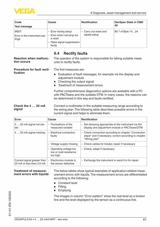
61
9 Diagnosis, asset management and service
VEGAPULS 64 • 4 … 20 mA/HART - two-wire
5114
1-EN
-160
303
CodeText message
Cause Rectification DevSpec State in CMD 48
M507Error in the instrument set-tings
– Error during setup – Error when carrying out
a reset – False signal suppression
faulty
– Carry out reset and repeat setup
Bit 7 of Byte 14…24
9.4 Rectify faultsThe operator of the system is responsible for taking suitable meas-ures to rectify faults.
Thefirstmeasuresare:
• Evaluation of fault messages, for example via the display and adjustment module
• Checking the output signal• Treatment of measurement errors
Further comprehensive diagnostics options are available with a PC with PACTware and the suitable DTM. In many cases, the reasons can bedeterminedinthiswayandfaultsrectified.
Connect a multimeter in the suitable measuring range according to the wiring plan. The following table describes possible errors in the current signal and helps to eliminate them:
Error Cause Rectification
4 … 20 mA signal not sta-ble
– Fluctuations of the measured variable
– Set damping appropriate to the instrument via the display and adjustment module or PACTware/DTM
4 … 20 mA signal missing – Electrical connection faulty
– Check connection according to chapter "Connection steps" and if necessary, correct according to chapter "Wiring plan"
– Voltage supply missing – Check cables for breaks; repair if necessary
– Operating voltage too low or load resistance too high
– Check, adapt if necessary
Current signal greater than 22 mA or less than 3.6 mA
– Electronics module in the sensor defective
– Exchange the instrument or send it in for repair
The below tables show typical examples of application-related meas-urementerrorswithliquids.Themeasurementerrorsaredifferentiatedaccording to the following:
• Constant level• Filling• Emptying
The images in column "Error pattern" show the real level as a broken line and the level displayed by the sensor as a continuous line.
Reaction when malfunc-tion occurs
Procedure for fault recti-fication
Check the 4 … 20 mA signal
Treatment of measure-ment errors with liquids
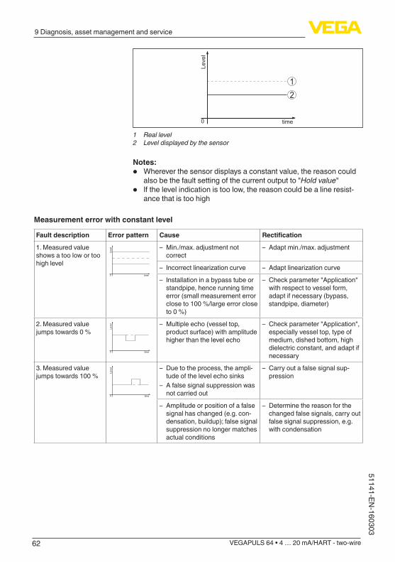
62
9 Diagnosis, asset management and service
VEGAPULS 64 • 4 … 20 mA/HART - two-wire
51141-EN-160303
12
Leve
l
time0
1 Real level2 Level displayed by the sensor
Notes:• Wherever the sensor displays a constant value, the reason could
also be the fault setting of the current output to "Hold value"• If the level indication is too low, the reason could be a line resist-
ance that is too high
Measurement error with constant level
Fault description Error pattern Cause Rectification
1. Measured value shows a too low or too high level
Leve
l
time0
– Min./max. adjustment not correct
– Adapt min./max. adjustment
– Incorrectlinearizationcurve – Adaptlinearizationcurve
– Installation in a bypass tube or standpipe, hence running time error (small measurement error close to 100 %/large error close to 0 %)
– Check parameter "Application" with respect to vessel form, adapt if necessary (bypass, standpipe, diameter)
2. Measured value jumps towards 0 % Le
vel
time0
– Multiple echo (vessel top, product surface) with amplitude higher than the level echo
– Check parameter "Application", especially vessel top, type of medium, dished bottom, high dielectric constant, and adapt if necessary
3. Measured value jumps towards 100 % Le
vel
time0
– Due to the process, the ampli-tude of the level echo sinks
– A false signal suppression was not carried out
– Carry out a false signal sup-pression
– Amplitude or position of a false signal has changed (e.g. con-densation, buildup); false signal suppression no longer matches actual conditions
– Determine the reason for the changed false signals, carry out false signal suppression, e.g. with condensation
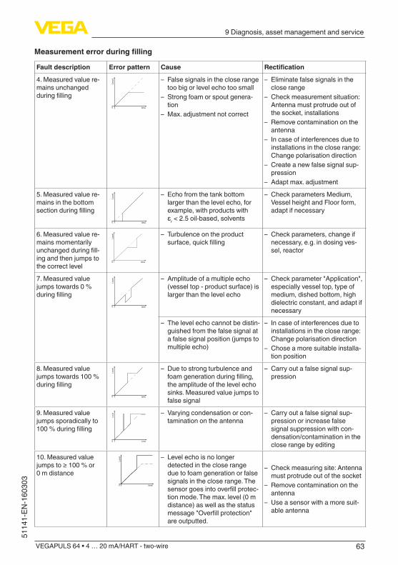
63
9 Diagnosis, asset management and service
VEGAPULS 64 • 4 … 20 mA/HART - two-wire
5114
1-EN
-160
303
Measurementerrorduringfilling
Fault description Error pattern Cause Rectification
4. Measured value re-mains unchanged duringfilling
Leve
l
time0
– False signals in the close range too big or level echo too small
– Strong foam or spout genera-tion
– Max. adjustment not correct
– Eliminate false signals in the close range
– Check measurement situation: Antenna must protrude out of the socket, installations
– Remove contamination on the antenna
– In case of interferences due to installations in the close range: Change polarisation direction
– Create a new false signal sup-pression
– Adapt max. adjustment
5. Measured value re-mains in the bottom sectionduringfilling
Leve
l
time0
– Echo from the tank bottom larger than the level echo, for example, with products with εr < 2.5 oil-based, solvents
– Check parameters Medium, Vessel height and Floor form, adapt if necessary
6. Measured value re-mains momentarily unchangedduringfill-ing and then jumps to the correct level
Leve
l
time0
– Turbulence on the product surface,quickfilling
– Check parameters, change if necessary, e.g. in dosing ves-sel, reactor
7. Measured value jumps towards 0 % duringfilling
Leve
l
time0
– Amplitude of a multiple echo (vessel top - product surface) is larger than the level echo
– Check parameter "Application", especially vessel top, type of medium, dished bottom, high dielectric constant, and adapt if necessary
– The level echo cannot be distin-guished from the false signal at a false signal position (jumps to multiple echo)
– In case of interferences due to installations in the close range: Change polarisation direction
– Chose a more suitable installa-tion position
8. Measured value jumps towards 100 % duringfilling
Leve
l
time0
– Due to strong turbulence and foamgenerationduringfilling,the amplitude of the level echo sinks. Measured value jumps to false signal
– Carry out a false signal sup-pression
9. Measured value jumps sporadically to 100%duringfilling
Level
time0
– Varying condensation or con-tamination on the antenna
– Carry out a false signal sup-pression or increase false signal suppression with con-densation/contamination in the close range by editing
10. Measured value jumpsto≥100%or0 m distance
Leve
l
time0
– Level echo is no longer detected in the close range due to foam generation or false signals in the close range. The sensorgoesintooverfillprotec-tion mode. The max. level (0 m distance) as well as the status message"Overfillprotection"are outputted.
– Check measuring site: Antenna must protrude out of the socket
– Remove contamination on the antenna
– Use a sensor with a more suit-able antenna
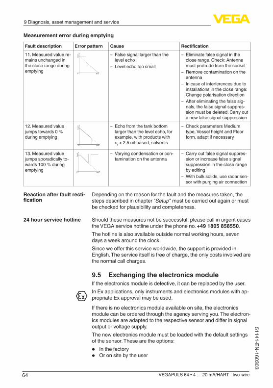
64
9 Diagnosis, asset management and service
VEGAPULS 64 • 4 … 20 mA/HART - two-wire
51141-EN-160303
Measurement error during emptying
Fault description Error pattern Cause Rectification
11. Measured value re-mains unchanged in the close range during emptying
Leve
l
time0
– False signal larger than the level echo
– Level echo too small
– Eliminate false signal in the close range. Check: Antenna must protrude from the socket
– Remove contamination on the antenna
– In case of interferences due to installations in the close range: Change polarisation direction
– After eliminating the false sig-nals, the false signal suppres-sion must be deleted. Carry out a new false signal suppression
12. Measured value jumps towards 0 % during emptying
Leve
l
time0
– Echo from the tank bottom larger than the level echo, for example, with products with εr < 2.5 oil-based, solvents
– Check parameters Medium type, Vessel height and Floor form, adapt if necessary
13. Measured value jumps sporadically to-wards 100 % during emptying
Leve
l
time0
– Varying condensation or con-tamination on the antenna
– Carry out false signal suppres-sion or increase false signal suppression in the close range by editing
– With bulk solids, use radar sen-sor with purging air connection
Depending on the reason for the fault and the measures taken, the steps described in chapter "Setup" must be carried out again or must be checked for plausibility and completeness.
Should these measures not be successful, please call in urgent cases the VEGA service hotline under the phone no. +49 1805 858550.The hotline is also available outside normal working hours, seven days a week around the clock.Sinceweofferthisserviceworldwide,thesupportisprovidedinEnglish. The service itself is free of charge, the only costs involved are the normal call charges.
9.5 Exchanging the electronics moduleIf the electronics module is defective, it can be replaced by the user.In Ex applications, only instruments and electronics modules with ap-propriate Ex approval may be used.
If there is no electronics module available on site, the electronics module can be ordered through the agency serving you. The electron-icsmodulesareadaptedtotherespectivesensoranddifferinsignaloutput or voltage supply.The new electronics module must be loaded with the default settings of the sensor. These are the options:
• In the factory• Or on site by the user
Reaction after fault recti-fication
24 hour service hotline
65
9 Diagnosis, asset management and service
VEGAPULS 64 • 4 … 20 mA/HART - two-wire
5114
1-EN
-160
303
In both cases, the serial number of the sensor is needed. The serial numbers are stated on the type label of the instrument, on the inside of the housing as well as on the delivery note.Whenloadingonsite,firstofalltheorderdatamustbedownloadedfrom the Internet (see operating instructions manual "Electronics module").
Caution:Alluser-specificsettingsmustbeenteredagain.Hence,youhavetocarry out a new setup after the electronics exchange.If you have stored the data of the parameter adjustment during the firstsetupofthesensor,youcantransferthesetothereplacementelectronics module. A new setup is no more necessary.
9.6 Software updateThe following components are required to update the instrument software:
• Instrument• Voltage supply• Interface adapter VEGACONNECT• PC with PACTware• CurrentinstrumentsoftwareasfileYoucanfindthecurrentinstrumentsoftwareaswellasdetailedinformation on the procedure in the download area of our homepage: www.vega.com.
Caution:Instruments with approvals can be bound to certain software versions. Thereforemakesurethattheapprovalisstilleffectiveafterasoftwareupdate is carried out.Youcanfinddetailedinformationinthedownloadareaatwww.vega.com.
9.7 How to proceed if a repair is necessaryYoucanfindaninstrumentreturnformaswellasdetailedinfor-mation of the procedure in the download area on our homepage: www.vega.com.By doing this you help us carry out the repair quickly and without hav-ing to call back for needed information.If a repair is necessary, please proceed as follows:
• Printandfilloutoneformperinstrument• Clean the instrument and pack it damage-proof• Attach the completed form and, if need be, also a safety data
sheet outside on the packaging• Please contact the agency serving you to get the address for
thereturnshipment.Youcanfindtheagencyonourhomepagewww.vega.com.
66
10 Dismount
VEGAPULS 64 • 4 … 20 mA/HART - two-wire
51141-EN-160303
10 Dismount
10.1 Dismounting stepsWarning:Before dismounting, be aware of dangerous process conditions such as e.g. pressure in the vessel or pipeline, high temperatures, cor-rosive or toxic products etc.
Take note of chapters "Mounting" and "Connecting to power supply" and carry out the listed steps in reverse order.
10.2 DisposalThe instrument consists of materials which can be recycled by spe-cialised recycling companies. We use recyclable materials and have designed the parts to be easily separable.Correctdisposalavoidsnegativeeffectsonhumansandtheenviron-ment and ensures recycling of useful raw materials.Materials: see chapter "Technical data"If you have no way to dispose of the old instrument properly, please contact us concerning return and disposal.
WEEE directive 2002/96/EGThis instrument is not subject to the WEEE directive 2002/96/EG and the respective national laws. Pass the instrument directly on to a spe-cialised recycling company and do not use the municipal collecting points. These may be used only for privately used products according to the WEEE directive.
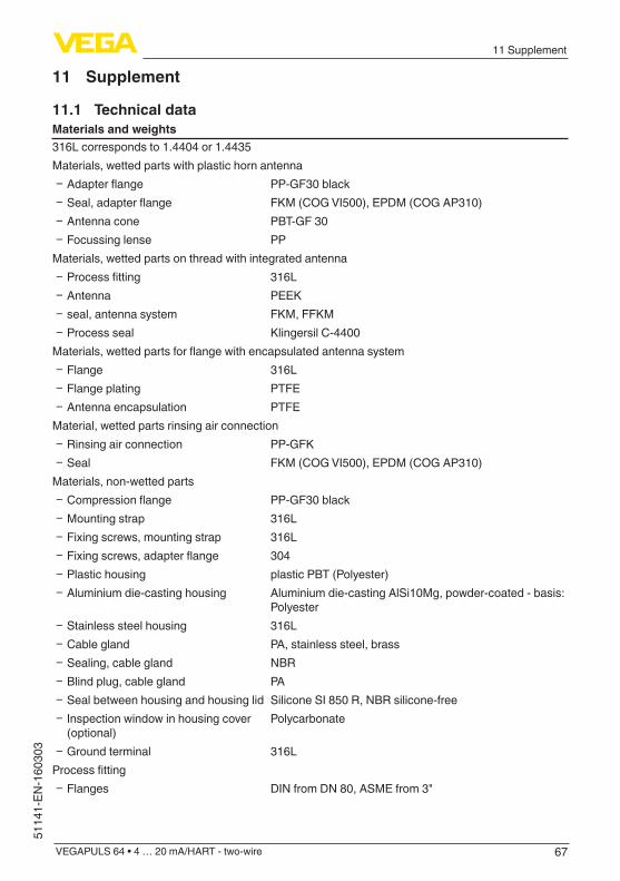
67
11 Supplement
VEGAPULS 64 • 4 … 20 mA/HART - two-wire
5114
1-EN
-160
303
11 Supplement
11.1 Technical dataMaterials and weights316L corresponds to 1.4404 or 1.4435Materials, wetted parts with plastic horn antenna
Ʋ Adapterflange PP-GF30 black Ʋ Seal,adapterflange FKM (COG VI500), EPDM (COG AP310) Ʋ Antenna cone PBT-GF 30 Ʋ Focussing lense PP
Materials, wetted parts on thread with integrated antenna Ʋ Processfitting 316L Ʋ Antenna PEEK Ʋ seal, antenna system FKM, FFKM Ʋ Process seal Klingersil C-4400
Materials,wettedpartsforflangewithencapsulatedantennasystem Ʋ Flange 316L Ʋ Flange plating PTFE Ʋ Antenna encapsulation PTFE
Material, wetted parts rinsing air connection Ʋ Rinsing air connection PP-GFK Ʋ Seal FKM (COG VI500), EPDM (COG AP310)
Materials, non-wetted parts Ʋ Compressionflange PP-GF30 black Ʋ Mounting strap 316L Ʋ Fixing screws, mounting strap 316L Ʋ Fixingscrews,adapterflange 304 Ʋ Plastic housing plastic PBT (Polyester) Ʋ Aluminium die-casting housing Aluminium die-casting AlSi10Mg, powder-coated - basis:
Polyester Ʋ Stainless steel housing 316L Ʋ Cable gland PA, stainless steel, brass Ʋ Sealing, cable gland NBR Ʋ Blind plug, cable gland PA Ʋ Seal between housing and housing lid Silicone SI 850 R, NBR silicone-free Ʋ Inspection window in housing cover (optional)
Polycarbonate
Ʋ Ground terminal 316LProcessfitting
Ʋ Flanges DIN from DN 80, ASME from 3"

68
11 Supplement
VEGAPULS 64 • 4 … 20 mA/HART - two-wire
51141-EN-160303
Weights Ʋ Instrument (depending on housing, processfittingandantenna)
approx. 2 … 17.2 kg (4.409 … 37.92 lbs)
TorquesMax. torques, threaded version
Ʋ G¾ 30 Nm (22.13 lbf ft) Ʋ G1½ 200 Nm (147.5 lbf ft)
Max. torques, version plastic horn antenna Ʋ Mounting screws, mounting strap on sensor housing
4 Nm (2.950 lbf ft)
Ʋ Flangescrews,compressionflangeDN 80
5 Nm (3.689 lbf ft)
Ʋ Flangescrews,adapterflangeDN100 7 Nm (5.163 lbf ft)Torques,versionflangewithencapsulatedantennasystem
Ʋ Requiredtorqueoftheflangescrews 60 Nm (44.25 lbf ft) Ʋ Recommended torque for tightening theflangescrews
60 … 100 Nm (44.25 … 73.76 lbf ft)
Max. torques for NPT cable glands and Conduit tubes Ʋ Plastic housing 10 Nm (7.376 lbf ft) Ʋ Aluminium/Stainless steel housing 50 Nm (36.88 lbf ft)
Input variableMeasured variable The measured quantity is the distance between the end
of the sensor antenna and the product surface. The ref-erence plane for the measurement is the sealing surface onthehexagonorthelowersideoftheflange.
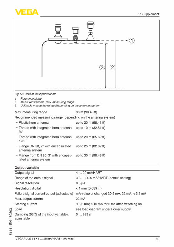
69
11 Supplement
VEGAPULS 64 • 4 … 20 mA/HART - two-wire
5114
1-EN
-160
303
2
1
3
Fig. 55: Data of the input variable1 Reference plane2 Measured variable, max. measuring range3 Utilisable measuring range (depending on the antenna system)
Max. measuring range 30 m (98.43 ft)Recommended measuring range (depending on the antenna system)
Ʋ Plastic horn antenna up to 30 m (98.43 ft) Ʋ Thread with integrated horn antenna ¾"
up to 10 m (32.81 ft)
Ʋ Thread with integrated horn antenna 1½"
up to 20 m (65.62 ft)
Ʋ Flange DN 50, 2" with encapsulated antenna system
up to 25 m (82.02 ft)
Ʋ Flange from DN 80, 3" with encapsu-lated antenna system
up to 30 m (98.43 ft)
Output variableOutput signal 4 … 20 mA/HARTRange of the output signal 3.8 … 20.5 mA/HART (default setting)Signal resolution 0.3 µAResolution, digital < 1 mm (0.039 in)Failure signal current output (adjustable) mA-value unchanged 20.5 mA, 22 mA, < 3.6 mAMax. output current 22 mAStarting current ≤3.6mA;≤10mAfor5msafterswitchingonLoad see load diagram under Power supplyDamping (63 % of the input variable), adjustable
0 … 999 s
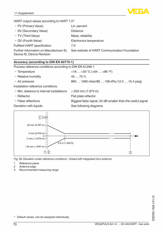
70
11 Supplement
VEGAPULS 64 • 4 … 20 mA/HART - two-wire
51141-EN-160303
HART output values according to HART 7.01)
Ʋ PV (Primary Value) Lin. percent Ʋ SV (Secondary Value) Distance Ʋ TV (Third Value) Meas. reliability Ʋ QV (Fourth Value) Electronics temperature
FulfilledHARTspecification 7.0Further information on Manufacturer ID, Device ID, Device Revision
See website of HART Communication Foundation
Accuracy (according to DIN EN 60770-1)Process reference conditions according to DIN EN 61298-1
Ʋ Temperature +18 … +30 °C (+64 … +86 °F) Ʋ Relative humidity 45 … 75 % Ʋ Air pressure 860 … 1060 mbar/86 … 106 kPa (12.5 … 15.4 psig)
Installation reference conditions Ʋ Min. distance to internal installations > 200 mm (7.874 in) Ʋ Reflector Flatplatereflector Ʋ Falsereflections Biggest false signal, 20 dB smaller than the useful signal
Deviation with liquids See following diagrams
0,5 m (1.640 ft)
20 mm (0.787 in)
- 20 mm (- 0787 in)
2 mm (0.079 in)
- 2 mm (- 0.079 in)0
1 2 3
Fig. 56: Deviation under reference conditions - thread with integrated horn antenna1 Reference plane2 Antenna edge3 Recommended measuring range
1) Default values, can be assigned individually.

71
11 Supplement
VEGAPULS 64 • 4 … 20 mA/HART - two-wire
5114
1-EN
-160
303
0,5 m (1.640 ft)
20 mm (0.787 in)
- 20 mm (- 0.787 in)
2 mm (0.079 in)
- 2 mm (- 0.079 in)0
1 2 3
Fig. 57: Deviation under reference conditions - plastic horn antenna1 Reference plane2 Antenna edge3 Recommended measuring range
0,5 m (1.640 ft)
20 mm (0.787 in)
- 20 mm (- 0.787 in)
02 mm (0.079 in)
- 2 mm (- 0.079 in)
1
3
2
Fig. 58: Deviation under reference conditions - flange with encapsulated antenna system1 Reference plane2 Antenna edge3 Recommended measuring range
Repeatability ≤±1mmDeviation with bulk solids The values depend to a great extent on the application.
Bindingspecificationsarethusnotpossible.
VariablesinfluencingmeasurementaccuracySpecificationsapplytothedigitalmeasuredvalueTemperature drift - Digital output ±3mm/10K,max.10mmAdditional deviation through electromag-netic interference acc. to EN 61326-2-3
None
SpecificationsapplyalsotothecurrentoutputTemperature drift - Current output ±0.03%/10Krelatingtothe16mAspanmax.±0.3%
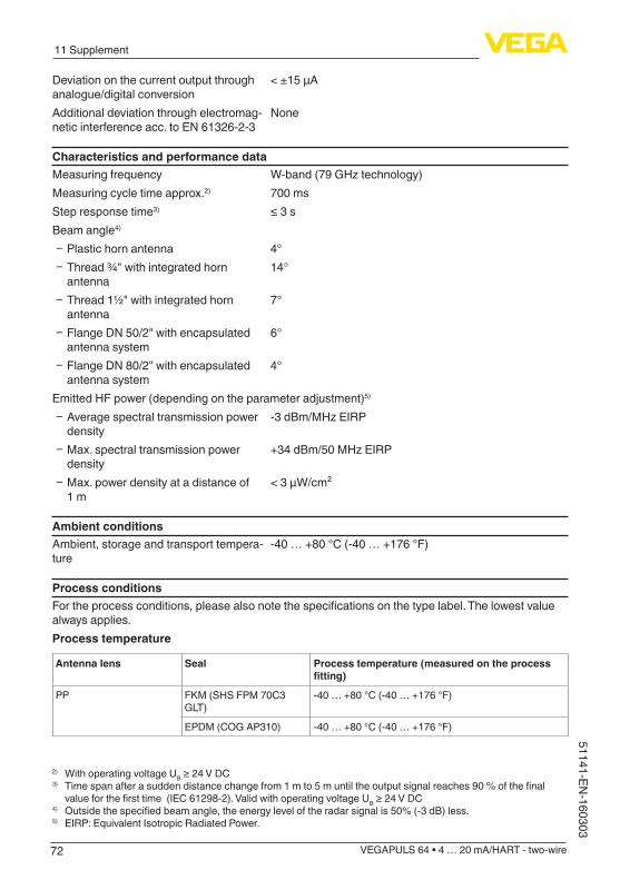
72
11 Supplement
VEGAPULS 64 • 4 … 20 mA/HART - two-wire
51141-EN-160303
Deviation on the current output through analogue/digital conversion
<±15µA
Additional deviation through electromag-netic interference acc. to EN 61326-2-3
None
Characteristics and performance dataMeasuring frequency W-band(79GHztechnology)Measuring cycle time approx.2) 700 msStep response time3) ≤3sBeam angle4)
Ʋ Plastic horn antenna 4° Ʋ Thread ¾" with integrated horn antenna
14°
Ʋ Thread 1½" with integrated horn antenna
7°
Ʋ Flange DN 50/2" with encapsulated antenna system
6°
Ʋ Flange DN 80/2" with encapsulated antenna system
4°
Emitted HF power (depending on the parameter adjustment)5)
Ʋ Average spectral transmission power density
-3dBm/MHzEIRP
Ʋ Max. spectral transmission power density
+34dBm/50MHzEIRP
Ʋ Max. power density at a distance of 1 m
< 3 µW/cm²
Ambient conditionsAmbient, storage and transport tempera-ture
-40 … +80 °C (-40 … +176 °F)
Process conditionsFortheprocessconditions,pleasealsonotethespecificationsonthetypelabel.Thelowestvaluealways applies.Process temperature
Antenna lens Seal Process temperature (measured on the process fitting)
PP FKM (SHS FPM 70C3 GLT)
-40 … +80 °C (-40 … +176 °F)
EPDM (COG AP310) -40 … +80 °C (-40 … +176 °F)
2) With operating voltage UB≥24VDC3) Timespanafterasuddendistancechangefrom1mto5muntiltheoutputsignalreaches90%ofthefinalvalueforthefirsttime(IEC61298-2).ValidwithoperatingvoltageUB≥24VDC
4) Outsidethespecifiedbeamangle,theenergyleveloftheradarsignalis50%(-3dB)less.5) EIRP: Equivalent Isotropic Radiated Power.
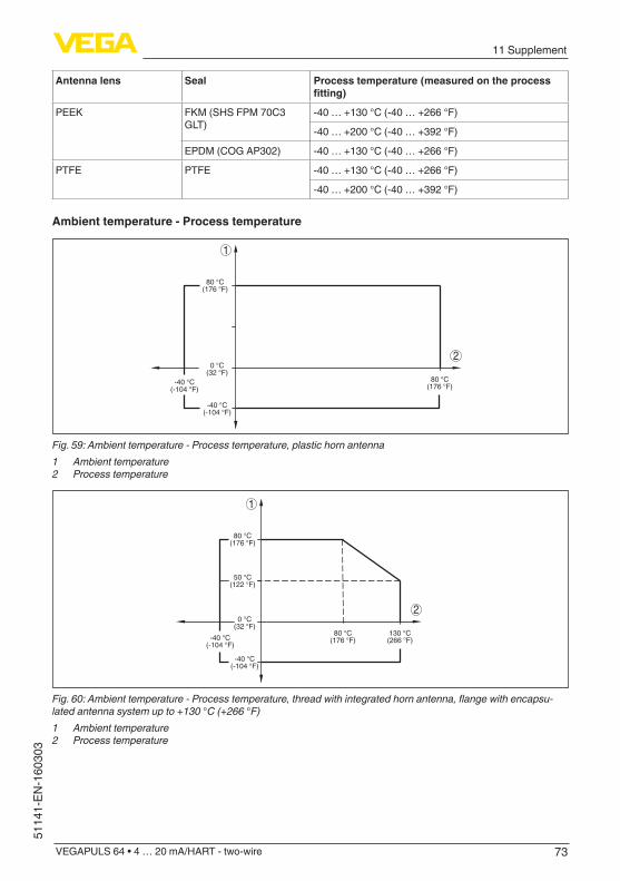
73
11 Supplement
VEGAPULS 64 • 4 … 20 mA/HART - two-wire
5114
1-EN
-160
303
Antenna lens Seal Process temperature (measured on the process fitting)
PEEK FKM (SHS FPM 70C3 GLT)
-40 … +130 °C (-40 … +266 °F)
-40 … +200 °C (-40 … +392 °F)
EPDM (COG AP302) -40 … +130 °C (-40 … +266 °F)
PTFE PTFE -40 … +130 °C (-40 … +266 °F)
-40 … +200 °C (-40 … +392 °F)
Ambient temperature - Process temperature
1
20 °C
(32 °F)
-40 °C(-104 °F)
80 °C(176 °F)
80 °C(176 °F)-40 °C
(-104 °F)
Fig. 59: Ambient temperature - Process temperature, plastic horn antenna1 Ambient temperature2 Process temperature
1
20 °C
(32 °F)
-40 °C(-104 °F)
50 °C(122 °F)
80 °C(176 °F)
130 °C(266 °F)
80 °C(176 °F)-40 °C
(-104 °F)
Fig. 60: Ambient temperature - Process temperature, thread with integrated horn antenna, flange with encapsu-lated antenna system up to +130 °C (+266 °F)1 Ambient temperature2 Process temperature

74
11 Supplement
VEGAPULS 64 • 4 … 20 mA/HART - two-wire
51141-EN-160303
1
20 °C
(32 °F)
-40 °C(-104 °F)
50 °C(122 °F)
80 °C(176 °F)
200 °C(392 °F)
80 °C(176 °F)-40 °C
(-104 °F)
Fig. 61: Ambient temperature - Process temperature, thread with integrated horn antenna, flange with encapsu-lated antenna system up to +200 °C (+392 °F)1 Ambient temperature2 Process temperature
Vessel pressureVessel pressure
Ʋ Plastic horn antenna -1 … 2 bar (-100 … 200 kPa/-14.5 … 29.1 psig) Ʋ Plastic horn antenna - Version with adapterflangefromDN100PPorPP-GF 30
-1 … 1 bar (-100 … 100 kPa/-14.5 … 14.5 psig)
Ʋ Thread with integrated horn antenna -1 … 20 bar (-100 … 2000 kPa/-14.5 … 290.1 psig) Ʋ Flange with encapsulated antenna system
-1 … 16 bar (-100 … 2000 kPa/-14.5 … 232.0 psig)
Vesselpressurerelatingtotheflangenominal pressure stage
see supplementary instructions manual "Flanges ac-cording to DIN-EN-ASME-JIS"
Mechanial stressesVibration resistance - Plastic horn antenna
Ʋ Withadapterflange 2gat5…200HzaccordingtoEN60068-2-6(vibrationwith resonance)
Ʋ with mounting strap 1gat5…200HzaccordingtoEN60068-2-6(vibrationwith resonance)
Vibration resistance - Thread with integratedhornantenna,flangewithencapsulated antenna system
4gat5…200HzaccordingtoEN60068-2-6(vibrationwith resonance)
Shock resistance 100 g, 6 ms according to EN 60068-2-27 (mechanical shock)
Data on rinsing air connectionMax. permissible pressure 6 bar (87.02 psig)Air volume, depending on pressure (recommended range)
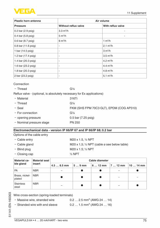
75
11 Supplement
VEGAPULS 64 • 4 … 20 mA/HART - two-wire
5114
1-EN
-160
303
Plastic horn antenna Air volume
Pressure Withoutrefluxvalve Withrefluxvalve
0.2 bar (2.9 psig) 3.3 m3/h -
0.4 bar (5.8 psig) 5 m3/h -
0.6 bar (8.7 psig) 6 m3/h 1 m3/h
0.8 bar (11.6 psig) - 2.1 m3/h
1 bar (14.5 psig) - 3 m3/h
1.2 bar (17.4 psig) - 3.5 m3/h
1.4 bar (20.3 psig) - 4.2 m3/h
1.6 bar (23.2 psig) - 4.4 m3/h
1.8 bar (20.3 psig) - 4.8 m3/h
2 bar (23.2 psig) - 5.1 m3/h
Connection Ʋ Thread G⅛
Refluxvalve-(optional,isabsolutelynecessaryforExapplications) Ʋ Material 316Ti Ʋ Thread G⅛ Ʋ Seal FKM (SHS FPM 70C3 GLT), EPDM (COG AP310) Ʋ For connection G⅛ Ʋ opening pressure 0.5 bar (7.25 psig) Ʋ Nominal pressure stage PN 250
Electromechanical data - version IP 66/IP 67 and IP 66/IP 68; 0.2 barOptions of the cable entry
Ʋ Cable entry M20 x 1.5, ½ NPT Ʋ Cable gland M20 x 1,5; ½ NPT (cable ø see below table) Ʋ Blind plug M20 x 1.5; ½ NPT Ʋ Closing cap ½ NPT
Material ca-ble gland
Material seal insert
Cable diameter
4.5 … 8.5 mm 5 … 9 mm 6 … 12 mm 7 … 12 mm 10 … 14 mm
PA NBR – ● ● – ●
Brass, nickel-plated
NBR ● ● ● – –
Stainless steel
NBR – ● ● – ●
Wire cross-section (spring-loaded terminals) Ʋ Massive wire, stranded wire 0.2 … 2.5 mm² (AWG 24 … 14) Ʋ Stranded wire with end sleeve 0.2 … 1.5 mm² (AWG 24 … 16)
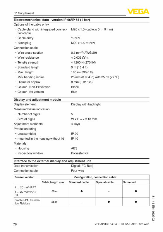
76
11 Supplement
VEGAPULS 64 • 4 … 20 mA/HART - two-wire
51141-EN-160303
Electromechanical data - version IP 66/IP 68 (1 bar)Options of the cable entry
Ʋ Cable gland with integrated connec-tion cable
M20 x 1.5 (cable: ø 5 … 9 mm)
Ʋ Cable entry ½ NPT Ʋ Blind plug M20 x 1.5; ½ NPT
Connection cable Ʋ Wire cross-section 0.5 mm² (AWG 20) Ʋ Wire resistance <0.036Ω/m Ʋ Tensile strength < 1200 N (270 lbf) Ʋ Standard length 5 m (16.4 ft) Ʋ Max. length 180 m (590.6 ft) Ʋ Min. bending radius 25 mm (0.984 in) with 25 °C (77 °F) Ʋ Diameter approx. 8 mm (0.315 in) Ʋ Colour - Non-Ex version Black Ʋ Colour - Ex-version Blue
Display and adjustment moduleDisplay element Display with backlightMeasured value indication
Ʋ Number of digits 5 Ʋ Sizeofdigits W x H = 7 x 13 mm
Adjustment elements 4 keysProtection rating
Ʋ unassembled IP 20 Ʋ mounted in the housing without lid IP 40
Materials Ʋ Housing ABS Ʋ Inspection window Polyester foil
Interface to the external display and adjustment unitData transmission Digital (I²C-Bus)Connection cable Four-wire
Sensor version Configuration,connectioncable
Cable length max. Standard cable Special cable Screened
4 … 20 mA/HART4 … 20 mA/HART SIL
50 m ● – ●
ProfibusPA,Founda-tion Fieldbus 25 m – ● ●
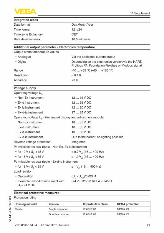
77
11 Supplement
VEGAPULS 64 • 4 … 20 mA/HART - two-wire
5114
1-EN
-160
303
Integrated clockDate format Day.Month.YearTime format 12 h/24 hTimezoneExfactory CETRate deviation max. 10.5 min/year
Additional output parameter - Electronics temperatureOutput of the temperature values
Ʋ Analogue Via the additional current output Ʋ Digital Depending on the electronics version via the HART,
ProfibusPA,FoundationFieldbusorModbussignalRange -40 … +85 °C (-40 … +185 °F)Resolution < 0.1 KAccuracy ±3K
Voltage supplyOperating voltage UB
Ʋ Non-Ex instrument 12 … 35 V DC Ʋ Ex-d instrument 12 … 35 V DC Ʋ Ex ia instrument 12 … 30 V DC Ʋ Ex-d-ia instrument 17 … 35 V DC
Operating voltage UB - illuminated display and adjustment module Ʋ Non-Ex instrument 18 … 35 V DC Ʋ Ex-d instrument 18 … 35 V DC Ʋ Ex ia instrument 18 … 30 V DC Ʋ Ex-d-ia instrument Due to the barrier, no lighting possible
Reverse voltage protection IntegratedPermissible residual ripple - Non-Ex, Ex-ia instrument
Ʋ for 12 V< UB < 18 V ≤0.7Veff(16…400Hz) Ʋ for 18 V< UB < 35 V ≤1.0Veff(16…400Hz)
Permissible residual ripple - Ex-d-ia instrument Ʋ for 18 V< UB < 35 V ≤1Veff(16…400Hz)
Load resistor Ʋ Calculation (UB - Umin)/0.022 A Ʋ Example - Non-Ex instrument with UB= 24 V DC
(24V-12V)/0.022A=545Ω
Electrical protective measuresProtection rating
Housing material Version IP-protection class NEMA protection
Plastic Single chamber IP 66/IP 67 NEMA4X
Double chamber IP 66/IP 67 NEMA4X
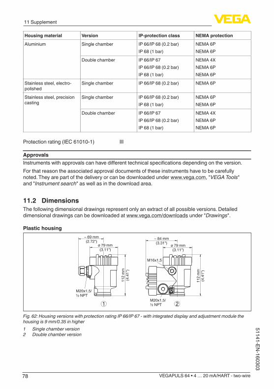
78
11 Supplement
VEGAPULS 64 • 4 … 20 mA/HART - two-wire
51141-EN-160303
Housing material Version IP-protection class NEMA protection
Aluminium Single chamber IP 66/IP 68 (0.2 bar)IP 68 (1 bar)
NEMA 6PNEMA 6P
Double chamber IP 66/IP 67IP 66/IP 68 (0.2 bar)IP 68 (1 bar)
NEMA4XNEMA 6PNEMA 6P
Stainless steel, electro-polished
Single chamber IP 66/IP 68 (0.2 bar) NEMA 6P
Stainless steel, precision casting
Single chamber IP 66/IP 68 (0.2 bar)IP 68 (1 bar)
NEMA 6PNEMA 6P
Double chamber IP 66/IP 67IP 66/IP 68 (0.2 bar)IP 68 (1 bar)
NEMA4XNEMA 6PNEMA 6P
Protection rating (IEC 61010-1) III
ApprovalsInstrumentswithapprovalscanhavedifferenttechnicalspecificationsdependingontheversion.For that reason the associated approval documents of these instruments have to be carefully noted. They are part of the delivery or can be downloaded under www.vega.com, "VEGA Tools" and "Instrument search" as well as in the download area.
11.2 DimensionsThe following dimensional drawings represent only an extract of all possible versions. Detailed dimensional drawings can be downloaded at www.vega.com/downloads under "Drawings".
Plastic housing~ 69 mm(2.72")
ø 79 mm(3.11")
112
mm
(4.4
1")
M20x1,5/½ NPT
~ 84 mm(3.31")
M16x1,5
112
mm
(4.4
1")
M20x1,5/½ NPT1 2
ø 79 mm(3.11")
Fig. 62: Housing versions with protection rating IP 66/IP 67 - with integrated display and adjustment module the housing is 9 mm/0.35 in higher1 Single chamber version2 Double chamber version
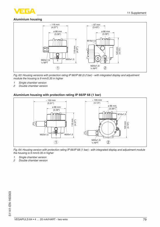
79
11 Supplement
VEGAPULS 64 • 4 … 20 mA/HART - two-wire
5114
1-EN
-160
303
Aluminium housing
21
ø 86 mm(3.39")
~ 116 mm(4.57")
116
mm
(4.5
7")
M20x1,5M20x1,5/½ NPT
~ 87 mm(3.43")
M16x1,5
ø 86 mm(3.39")
120
mm
(4.7
2")
M20x1,5/½ NPT
Fig. 63: Housing versions with protection rating IP 66/IP 68 (0.2 bar) - with integrated display and adjustment module the housing is 9 mm/0.35 in higher1 Single chamber version2 Double chamber version
Aluminium housing with protection rating IP 66/IP 68 (1 bar)
120
mm
(4.7
2")
~ 105 mm(4.13")
116
mm
(4.5
7")
~ 150 mm(5.91")
ø 86 mm(3.39")
ø 86 mm(3.39")
M20x1,5/½ NPT
M16x1,5
2
M20x1,5M20x1,5
1
Fig. 64: Housing version with protection rating IP 66/IP 68 (1 bar) - with integrated display and adjustment module the housing is 9 mm/0.35 in higher1 Single chamber version2 Double chamber version

80
11 Supplement
VEGAPULS 64 • 4 … 20 mA/HART - two-wire
51141-EN-160303
Stainless steel housing~ 69 mm(2.72")
ø 79 mm(3.11")
117
mm
(4.6
1")
M20x1,5/½ NPT
~ 59 mm(2.32")
ø 80 mm(3.15")
112
mm
(4.4
1")
M20x1,5/½ NPT
~ 87 mm(3.43")
ø 86 mm(3.39")
120
mm
(4.7
2")
M20x1,5/½ NPT
M16x1,5
321
Fig. 65: Housing versions with protection rating IP 66/IP 68 (0.2 bar) - with integrated display and adjustment module the housing is 9 mm/0.35 in higher1 Single chamber version, electropolished2 Single chamber version, precision casting3 Double chamber version, precision casting
Stainless steel housing with protection rating IP 66/IP 68, 1 bar11
7 m
m(4
.61"
)
~ 103 mm(4.06") ø 79 mm
(3.11")
120
mm
(4.7
2")
~ 105 mm(4.13") ø 86 mm
(3.39")
M20x1,5
M20x1,5/½ NPT
M16x1,5
~ 93 mm(3.66") ø 80 mm
(3.15")
112
mm
(4.4
1")
M20x1,5/½ NPT
321
Fig. 66: Housing version with protection rating IP 66/IP 68 (1 bar) - with integrated display and adjustment module the housing is 9 mm/0.35 in higher1 Single chamber version, electropolished2 Single chamber version, precision casting3 Double chamber version, precision casting
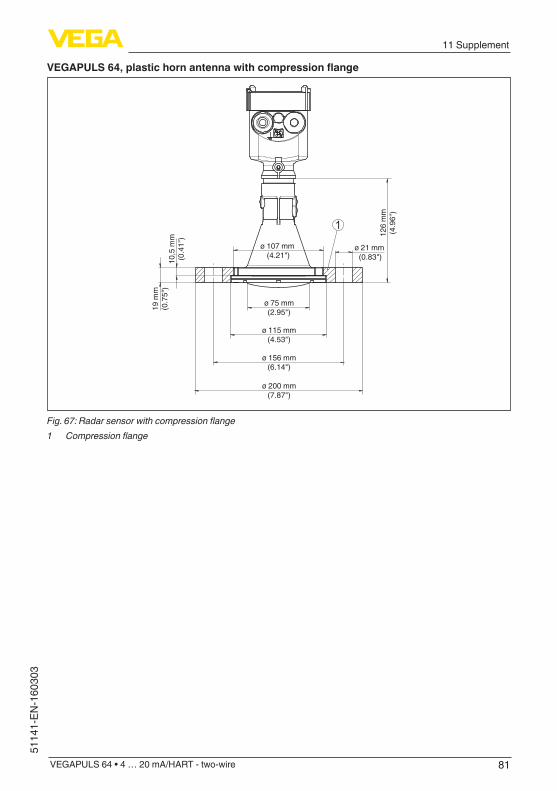
81
11 Supplement
VEGAPULS 64 • 4 … 20 mA/HART - two-wire
5114
1-EN
-160
303
VEGAPULS64,plastichornantennawithcompressionflange
126
mm
(4.9
6")
10,5
mm
(0.4
1")
19 m
m(0
.75"
)
ø 75 mm(2.95")
ø 115 mm(4.53")
ø 156 mm(6.14")
ø 200 mm(7.87")
ø 21 mm (0.83")
ø 107 mm (4.21")
1
Fig. 67: Radar sensor with compression flange1 Compression flange
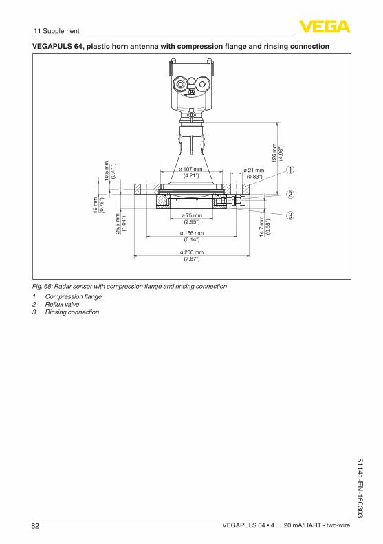
82
11 Supplement
VEGAPULS 64 • 4 … 20 mA/HART - two-wire
51141-EN-160303
VEGAPULS64,plastichornantennawithcompressionflangeandrinsingconnection
126
mm
(4.9
6")
14,7
mm
(0.5
8")
10,5
mm
(0.4
1")
26,5
mm
(1.0
4")
19 m
m(0
.75"
)
ø 75 mm(2.95")
ø 156 mm(6.14")
ø 200 mm(7.87")
ø 21 mm (0.83")
ø 107 mm (4.21")
1
2
3
Fig. 68: Radar sensor with compression flange and rinsing connection1 Compression flange2 Reflux valve3 Rinsing connection
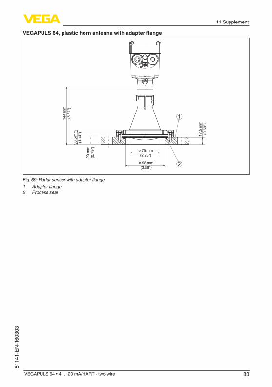
83
11 Supplement
VEGAPULS 64 • 4 … 20 mA/HART - two-wire
5114
1-EN
-160
303
VEGAPULS64,plastichornantennawithadapterflange
2
1144
mm
(5.6
7")
36,5
mm
(1.4
4")
20 m
m(0
.79"
)
17,5
mm
(0.6
9")
ø 75 mm(2.95")
ø 98 mm(3.86")
Fig. 69: Radar sensor with adapter flange1 Adapter flange2 Process seal

84
11 Supplement
VEGAPULS 64 • 4 … 20 mA/HART - two-wire
51141-EN-160303
VEGAPULS64,plastichornantennamitadapterflangeundrinsingconnection
3
21170
mm
(6.6
9")
62,5
mm
(2.4
6")
20 m
m(0
.79"
)
34,7
mm
(1.3
7")
ø 75 mm(2.95")
ø 98 mm(3.86")
Fig. 70: VEGAPULS 64, adapter flange and rinsing connection1 Rinsing air connection2 Reflux valve3 Adapter flange
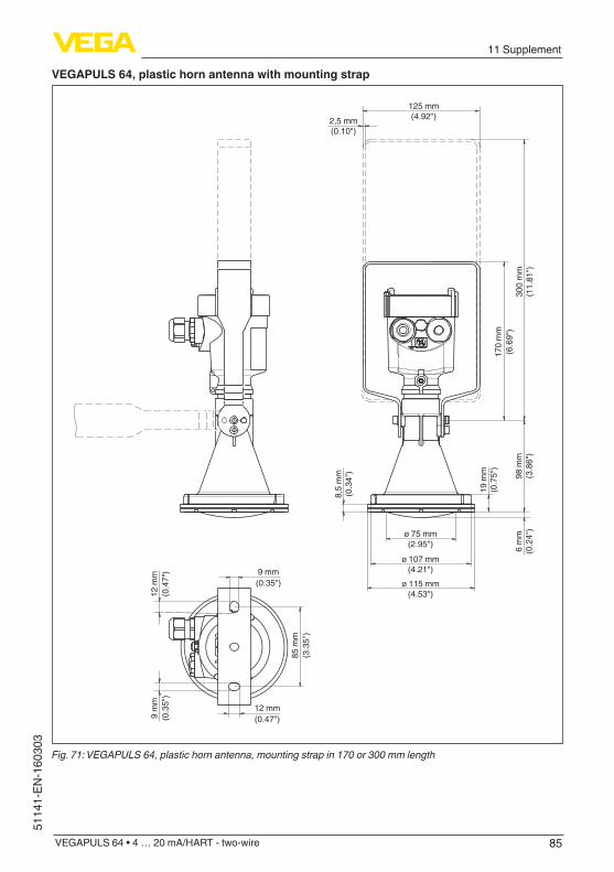
85
11 Supplement
VEGAPULS 64 • 4 … 20 mA/HART - two-wire
5114
1-EN
-160
303
VEGAPULS 64, plastic horn antenna with mounting strap
125 mm(4.92")2,5 mm
(0.10")
ø 75 mm(2.95")
ø 107 mm(4.21")
ø 115 mm(4.53")
300
mm
(11.
81")
19 m
m(0
.75"
)
98 m
m(3
.86"
)6
mm
(0.2
4")
8,5
mm
(0.3
4")
9 mm(0.35")
85 m
m(3
.35"
)
12 m
m(0
.47"
)9
mm
(0.3
5")
12 mm(0.47")
170
mm
(6.6
9")
Fig. 71: VEGAPULS 64, plastic horn antenna, mounting strap in 170 or 300 mm length
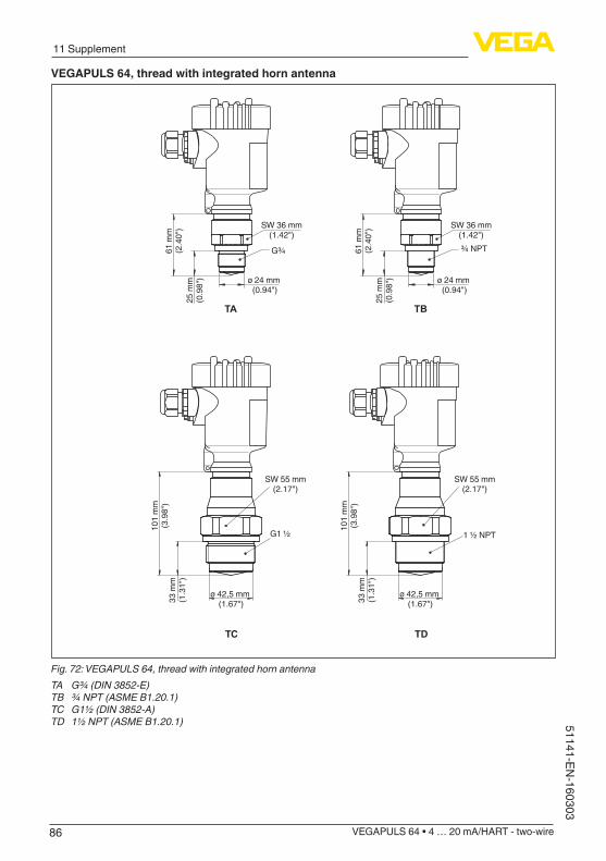
86
11 Supplement
VEGAPULS 64 • 4 … 20 mA/HART - two-wire
51141-EN-160303
VEGAPULS 64, thread with integrated horn antenna
TA
25 m
m(0
.98"
)
61 m
m(2
.40"
)
ø 24 mm (0.94")
SW 36 mm(1.42")
G¾
TB
25 m
m(0
.98"
)
61 m
m(2
.40"
)
ø 24 mm (0.94")
SW 36 mm(1.42")¾ NPT
G1 ½101
mm
(3.9
8")
33 m
m(1
.31"
)
ø 42,5 mm (1.67")
ø 42,5 mm (1.67")
1 ½ NPT
SW 55 mm(2.17")
101
mm
(3.9
8")
33 m
m(1
.31"
)
SW 55 mm(2.17")
TC TD
Fig. 72: VEGAPULS 64, thread with integrated horn antennaTA G¾ (DIN 3852-E)TB ¾ NPT (ASME B1.20.1)TC G1½ (DIN 3852-A)TD 1½ NPT (ASME B1.20.1)
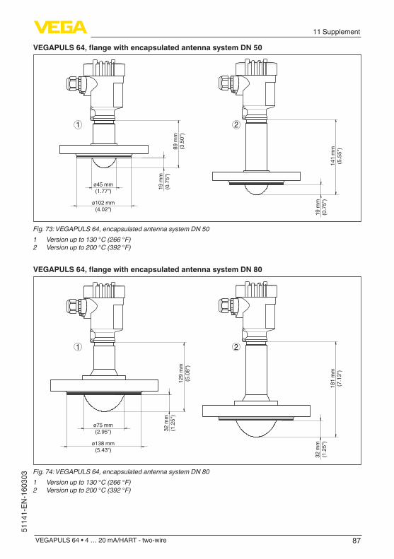
87
11 Supplement
VEGAPULS 64 • 4 … 20 mA/HART - two-wire
5114
1-EN
-160
303
VEGAPULS64,flangewithencapsulatedantennasystemDN50
21
141
mm
(5.5
5")89
mm
(3.5
0")
19 m
m(0
.75"
)
ø45 mm(1.77")
ø102 mm(4.02")
19 m
m(0
.75"
)
Fig. 73: VEGAPULS 64, encapsulated antenna system DN 501 Version up to 130 °C (266 °F)2 Version up to 200 °C (392 °F)
VEGAPULS64,flangewithencapsulatedantennasystemDN80
181
mm
(7.1
3")
129
mm
(5.0
8")
32 m
m(1
.25"
)
ø75 mm(2.95")
ø138 mm(5.43")
32 m
m(1
.25"
)
21
Fig. 74: VEGAPULS 64, encapsulated antenna system DN 801 Version up to 130 °C (266 °F)2 Version up to 200 °C (392 °F)

88
11 Supplement
VEGAPULS 64 • 4 … 20 mA/HART - two-wire
51141-EN-160303
11.3 Industrial property rightsVEGA product lines are global protected by industrial property rights. Further information see www.vega.com.VEGA Produktfamilien sind weltweit geschützt durch gewerbliche Schutzrechte.Nähere Informationen unter www.vega.com.Les lignes de produits VEGA sont globalement protégées par des droits de propriété intellec-tuelle. Pour plus d'informations, on pourra se référer au site www.vega.com.VEGA lineas de productos están protegidas por los derechos en el campo de la propiedad indus-trial. Para mayor información revise la pagina web www.vega.com.Линии продукции фирмы ВЕГА защищаются по всему миру правами на интеллектуальную собственность. Дальнейшую информацию смотрите на сайте www.vega.com.VEGA系列产品在全球享有知识产权保护。进一步信息请参见网站<www.vega.com。
11.4 TrademarkAll the brands as well as trade and company names used are property of their lawful proprietor/originator.
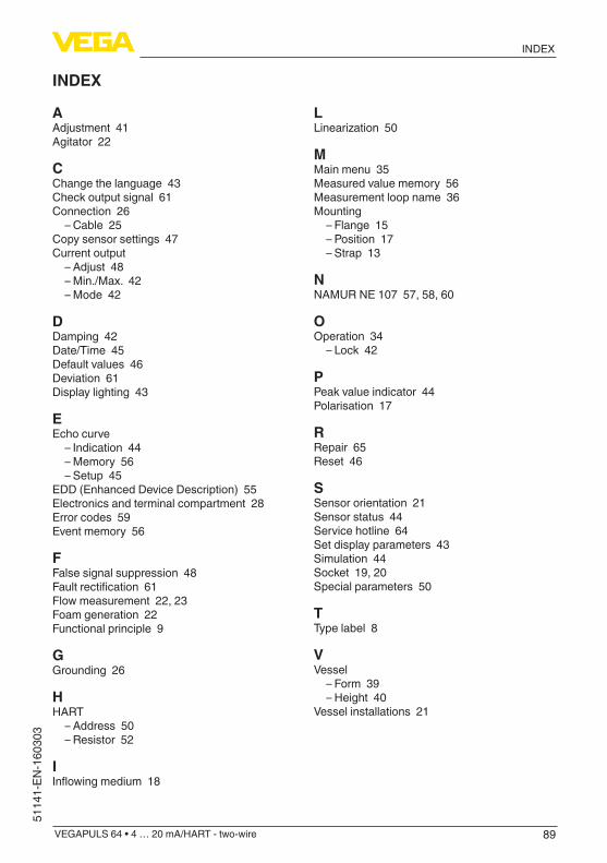
89
INDEX
VEGAPULS 64 • 4 … 20 mA/HART - two-wire
5114
1-EN
-160
303
INDEX
AAdjustment 41Agitator 22
CChange the language 43Check output signal 61Connection 26
– Cable 25Copy sensor settings 47Current output
– Adjust 48 – Min./Max. 42 – Mode 42
DDamping 42Date/Time 45Default values 46Deviation 61Display lighting 43
EEcho curve
– Indication 44 – Memory 56 – Setup 45
EDD (Enhanced Device Description) 55Electronics and terminal compartment 28Error codes 59Event memory 56
FFalse signal suppression 48Faultrectification61Flow measurement 22, 23Foam generation 22Functional principle 9
GGrounding 26
HHART
– Address 50 – Resistor 52
IInflowingmedium18
LLinearization50
MMain menu 35Measured value memory 56Measurement loop name 36Mounting
– Flange 15 – Position 17 – Strap 13
NNAMUR NE 107 57, 58, 60
OOperation 34
– Lock 42
PPeak value indicator 44Polarisation 17
RRepair 65Reset 46
SSensor orientation 21Sensor status 44Service hotline 64Set display parameters 43Simulation 44Socket 19, 20Special parameters 50
TType label 8
VVessel
– Form 39 – Height 40
Vessel installations 21

90
Notes
VEGAPULS 64 • 4 … 20 mA/HART - two-wire
51141-EN-160303
91
Notes
VEGAPULS 64 • 4 … 20 mA/HART - two-wire
5114
1-EN
-160
303

Printing date:
VEGA Grieshaber KGAm Hohenstein 11377761 SchiltachGermany
5114
1-E
N-1
6030
3
All statements concerning scope of delivery, application, practical use and operat-ing conditions of the sensors and processing systems correspond to the information available at the time of printing.Subject to change without prior notice
© VEGA Grieshaber KG, Schiltach/Germany 2016
Phone +49 7836 50-0Fax +49 7836 50-201E-mail: [email protected]