Embed Size (px)
Citation preview

Operating Instructionsfor your Ford & Doonan Ducted System

Congratulations on your new Ford & Doonan Air Conditioning System. You can rest assured you have received a system of the highest quality, backed by the very best customer service. Before operating the air conditioner, please read this operating manual carefully. It will advise you on how to operate the unit correctly, understand the air conditioner’s advanced features and help you in the unlikely event that a problem should occur.
Please keep this manual in a safe place for future reference.
Congratulations!
Thank you for purchasing Ford & Doonan Air Conditioning
1800 247 266 [email protected] fordanddoonan.com.au

Contents1. Important Safety Instructions ................................................4
2. Zone Operation......................................................................5
3. Outlets ..................................................................................6
4. Maintenance .........................................................................7
5. Common Queries ..................................................................8
6. Performance Expectations .....................................................9
7. Performance Tips ...........................................................10-11
Kardinya – Head Office 5 Weatherburn Way, Kardinya WA 6163
P: 08 9331 8800 | F: 08 9331 6600 [email protected]
Joondalup Unit 2, 80 Winton Road, Joondalup WA 6027
P: 08 9301 4288 | F: 08 9301 4299 [email protected]
Scan to view our Operation Videos on our website or visitfordanddoonan.com.au/operation-videos-and-manuals

1. Important Safety Instructions
Never remove any fixed covers on the indoor or outdoor unit. Removal of the covers may expose fast moving fan blades or electrical components operating at a hazardous voltage. Contact with the blades or high voltage components may result in injury or electric shock.
Never insert any objects into the openings of the indoor or outdoor unit. This may damage the product or result in injury to the person inserting the object.
Do not expose the indoor unit or remote controller to rain or moisture. Water or other fluids on the electrical components may result in fire or electric shock.
Always replace any blown fuse with a fuse of the same specification. The use of the
wrong fuse may allow the electrical wiring to overheat and catch on fire. If the correct type of fuse continues to blow, or the circuit breaker continues to trip, contact Ford & Doonan Service Department.
Never operate the air conditioner without the return air filter(s) in place. Operating the unit without the filter(s) will allow dust to enter the indoor unit and build up on the heat exchanger coil and fan motor. This will cause a malfunction of the unit, which will not be covered by warranty.
This electrical appliance is not intended for use by young children. Young children should be supervised to ensure that they do not play with the outdoor unit.
Main switchEnsure you are familiar with the location of the main switches for the air conditioning system. These switches are normally located adjacent to the outdoor unit and in the fuse box/switchboard.
If the air conditioner is not going to be used for an extended period of time or you are going away on holidays, the main
switch should be turned off to prevent accidental operation of the air conditioner. When turning the system back on, the main switch must be turned on at least 6 hours before the air conditioner is operated to warm up the compressor. Failure to do so may result in damage to the compressor, which will not be covered by warranty.
4

2. Zone OperationApplicable when your new system has zones fitted
• For operational instructions please refer to the attached sub manual (if applicable).
• It is possible to run all zones at the same time, however, the system will not be running very efficiently.
• You may operate two or more zones at once, depending on the capacity of your unit, design and heat load. For example, under maximum heat load (a hot day) it is better to have fewer zones on than under a low heat load (at night) when an extra zone may be turned on.
• We recommend turning on the living areas during the day and closing any bedrooms and other zones that are not needed. At night it is best to turn off any living areas and keep the bedroom zones open. This will allow the best efficiency of the system.
• The zones can take up to 2 minutes to open or close.
• If some zones do not have enough air flow check how many zones are open. Close off any zones that are not needed and see if air flow increases.
5

3. OutletsMulti-Directional outlets Multi-Directional outlets (if applicable) are designed to give maximum adjustment to airflow. Each of the four cores (called louvre panels) is adjustable by lifting and turning to direct air from one direction to another. For the distribution of cool air, the louvre panels are set to deflect air horizontally across the ceiling. For high ceilings and heating systems the louvre panels are adjusted to achieve 40% downward flow. For spot cooling and heating, the louvre panels oppose each other for a vertical down airflow. The outlets can be manually closed
during winter if the system is not used for heating, although this is not a necessity.
Sidewall registers
Sidewall registers (if applicable) have vertical and horizontal blades that are adjustable. The blades are manufactured not to rattle. Any adjustments are required to be done with the assistance of long nose pliers with insulation tape wrapped around the ends so the paint of the register is not damaged. Gently move the blades to the desired position.
ONE WAY TWO WAY TWO WAY TWO WAY
THREE WAY THREE WAY THREE WAY FOUR WAY
6

4. Maintenance1. Cleaning the air filter
If you have a clean air filter pack, please call your Ford & Doonan store to purchase a replacement filter. We recommend replacing the filter every 12 months, if you have allergies or pets, we recommend replacing the filter every 6 months.
To clean your filter, remove the filter, hose it down and leave it a couple of hours to dry. Once this is done do not forget to press the filter reset button on your air conditioning controller.
2. Cleaning the outside panel Cleaning of the outside panel is easy, by using a soft cloth or a cloth dampened by a neutral detergent solution. Never use paint thinner, other chemical products, or polishing powder when cleaning the outside panel. A good quality car polish can be applied to the painted surfaces to increase the paint’s durability.
3. When the unit is not being used for an extended period• Switch off the main power switch.
• Rust preventative coating has been applied to the outside cover. If corroded, repair by painting.
• Clean the condenser to remove dust and excess waste (leaves, paper, etc.).
4. Maintenance service contract recommended
To ensure your system delivers cool, fresh air throughout the year and that your warranty is valid, it’s essential you maintain it regularly. Preventative maintenance by qualified technicians has been proven to reduce the risk of failure of plant and equipment and maintain the efficiency of the overall installation.
Servicing by a qualified Ford & Doonan technician is recommended. For domestic operation of the air conditioning system we recommend an annual service. If equipment is subjected to heavy use a bi-annual service frequency is desirable.
Contact your Service Department (9331 8800) to set up automatic service reminders and ask about our three year service packages at a reduced cost.
We recommend replacing your
disposable filter every 12 months
WASHABLE filterDISPOSABLE filter
7

5. Common QueriesIf the air conditioning is not running or the cooling effect cannot be achieved as desired, check the following points before requesting repair or service.
If the air conditioner does not function please check the following:
Is the power switched ON?
Has the power fuse failed?
Is power supplied?
Has the circuit breaker tripped?
Is the temperature indicator set in the correct operating position, or to a position which is too high for the cooling operation?
How to perform a reboot of your air conditioning system
Before calling the Service Department please perform a reset of your air conditioning system. As any electrical appliance, power dropouts or surges can interrupt the operation of the system. In most cases a reboot is all that is required. In case the system has never been used before, make sure that the main switch has been turned on for at least 6 hours before using the air conditioning unit.
Locate the isolator switch at the outdoor unit. It is a big white switch at the outdoor unit. Turn it off and wait 3 minutes before turning it back on.
If the system does not reboot, or the fault still appears please call the Ford & Doonan Service Department.
Not cooling or heating as desired please check the following:
Is the thermostat set to the proper position to heating or cooling?
Is there an obstruction near the air intake or outlet port?
Is the air filter free from clogging by dust, dirt, etc.?
Are doors and windows completely closed?
Smoke coming from outdoor unit?
In cold weather you may see what appears to be smoke coming from the unit. This is just steam being released when the unit is in de-ice mode. Further you may notice the unit icing up and appearing frozen. This is normal as long as the system completes a de-ice cycle.
“Filter clean” displays
If a small tap or spanner symbol appears, this indicates it is time to clean or replace the filter. Press this switch to reset and clear the symbol once you have cleaned or replaced the filter. Please see Maintenance for more information on how to clean your filter. If the spanner symbol appears with a fault code, it is advising you of a problem and you will need to contact your Service Department.
Faults:If the “CHECK” indicator starts flashing, this means there is a fault at hand.
In this case, or if fault codes appear, please call your Service Department with the fault code, explain the problem and they will be able to assist with the issue.
8

6. Performance ExpectationsHot weather
Heat load calculations and manufacturers capacity ratings are based on an outside temperature of 36°C. When the temperature exceeds this, the performance of your air conditioner will fall away the hotter it gets and room temperatures will increase accordingly.
Cold weather
Heat load calculations and manufacturers capacity ratings are based on an outside temperature of 7°C. When the temperature is lower than this, the performance of your air conditioner will fall away the colder it gets and room temperatures will decrease accordingly. The above conditions do occur in Perth and there will be nothing wrong with your air conditioning unit when it happens.
Heating performance
Hot air rises and the room temperatures at different levels will be different. It is normal that some parts of the room will be warmer than others. The same applies on cooling mode but to a lesser degree.
Return air
Your system will usually be designed with one only return air grille. The area around the return air grille will always be drafty, and in Winter, always much cooler than the rooms. This is why we select hallways or other “non occupied rooms”. You will have to leave any room’s entry door ajar to allow the conditioned air to come back to the grille. You cannot close the door as performance will be affected. We have options to overcome these situations, so please discuss this with your consultant.
Zones
If we have installed zones, then they cannot all be turned on together without effecting performance. On low load days or nights your air conditioner can handle a larger area at one time. Your air conditioner can only handle the percentage of the home we mention in our letter at typical design temperatures. Turning on less zones will effectively increase the available capacity you have.
9

7. Performance Tips1. Temperature setting on your air conditioning unit
We recommend that in summer you set the cooling cycle at 24 degrees and in Winter the heating at 21 degrees. On very hot days (above 36 degrees) or cold days (below 7 degrees) one can increase the temperature in Summer and decrease in Winter, to keep the efficiency of the air conditioning.
2. To keep the comfortable temperature without extra heat loading
The easiest solution to start your air conditioner earlier in the day by using your timer setting. On hot days start the air conditioner before your heat load increases so the air conditioner can get a head start. On cold days start the air conditioner whilst it is still warm outside (above 12-15°C). This will let the air conditioner deliver maximum capacity before performance falls away. If your system has zones (residential only) reduce the number of zones turned on when
the external conditions are extreme. The smaller the area being air conditioned, the better it can cope.
3. Close doors of rooms that are not being air conditioned
When operating an air conditioning system that utilises the zoning technique, remember the system has only a certain capacity, therefore the idea is to air condition the areas you are occupying at the time. With this in mind, it becomes prudent to habitually close the doors that lead to a non air conditioned area, thereby reducing the total area being subjected to air conditioning. This will enhance the effectiveness of the machine.
4. Allow air flow to return air grille
You will notice that the larger return air grill is normally located in a central position in the building. It is important to encourage the airflow towards this grille. This grille is drawing the total air capacity of the system through it and therefore
10

requires unrestricted airflow. Depending upon the building, you may need to open or close doors around this area to keep the
air flowing to this grille.
5. Regular cleaning of the filter is important
The return air grille in most cases also contains an air filter. This air filter, depending on the system usage and other air quality factors, will need to be cleaned regularly. To do this, simply open the grille and slide out the filter. In most cases it is best to hose the filter clean, although some people prefer to vacuum the filter. Remember, regular cleaning of the filter will improve the system efficiency.
6. Clean outdoor unit and surroundings
The condensing or outdoor unit is located in a position to best suit the building and the occupants. It is important to maintain cleanliness around the unit, for example sweeping away any build-up of leaves or general flotsam. It is critical to not inhibit the airflow coming from the condenser, therefore general garden paraphernalia or other equipment should never be stacked
on or lent against the condenser. Similarly if a garden is developing around the condenser, this can be an advantage as some of the sound from the condensing unit will be absorbed, although a robust bush can block the air flow so consideration should be given to this. It is also imperative to keep the condensing unit accessible for servicing purposes.
7. Sizing of equipmentWhen we recommend a unit we have completed a heat load calculation on the area. We have assumed the following:
• Curtains will be drawn closed in both sunny Summer days and at night in Winter.
• Ceiling insulation has been installed directly above your ceiling (not just anti-con or sisalation)
• Doors and windows will be left closed.
If any of the above changes, your air conditioner may not be large enough to maintain acceptable room temperatures.
11

Panasonic Corporation1006 Kadoma, Kadoma City, Osaka, Japan
Operating InstructionsHigh-spec Wired Remote Controller
Model No. CZ-RTC5
Installation InstructionsSeparately Attached.
ENGLISHBefore operating the unit, read these operating instructions thoroughly and keep them for future reference.
CV6233312187 Panasonic Corporation http://www.panasonic.com

2 (EN)
Safety Precautions
CAUTIONSThis appliance is intended to be used by expert or trained users in shops, in light industry and on farms, or for commercial use by lay persons.This appliance can be used by children aged from 8 years and above and persons with reduced physical, sensory or mental capabilities or lack of experience and knowledge if they have been given supervision or instruction concerning use of the appliance in a safe way and understand the hazards involved.
WARNINGDo not use this appliance in a potentially explosive atmosphere.
• Do not operate with wet hands.• Do not wash with water.
In case of malfunction of this appliance, do not repair by yourself. Contact the sales or service dealer for repair.
In case of emergency, remove the power plug from the socket or switch off the circuit breaker or the means by which the system is isolated from the mains power.
WARNING CAUTION
This symbol refers to a hazard or unsafe practice which can result in severe personal injury or death.
This symbol refers to a hazard or unsafe practice which can result in personal injury or product or property damage.
Matters to be observed Prohibited matters

3(EN)
Note: This device complies with Part 15 of the FCC Rules. Operation is subject to the following two conditions: (1) This device may not cause harmful interference, and (2) this device must accept any interference received, including interference that may cause undesired operation. This equipment has been tested and found to comply with the limits for a Class B digital device, pursuant to Part 15 of the FCC Rules. These limits are designed to provide reasonable protection against harmful interference in a residential installation. This equipment generates, uses and can radiate radio frequency energy and, if not installed and used in accordance with the instructions, may cause harmful interference to radio communications. However, there is no guarantee that interference will not occur in a particular installation. If this equipment does cause harmful interference to radio or television reception, which can be determined by turning the equipment off and on, the user is encouraged to try to correct the interference by one or more of the following measures:• Reorient or relocate the receiving antenna.• Increase the separation between the equipment and receiver.• Connect the equipment into an outlet on a circuit different
from that to which the receiver is connected.• Consult the dealer or an experienced radio/TV technician
for help. FCC Caution: To assure continued compliance, follow the attached installation instructions. Any changes or modifi cations not expressly approved by the party responsible for compliance could void the user’s authority to operate this equipment.

4 (EN)
PreparationsH
ow to U
seSetting C
hangeW
hen N
ecessary
PageThank you for purchasing the Panasonic high-spec wired remote controller.
Read the Operating Instructions carefully for safe use. This manual describes the Operating Instructions of the wired remote controller. Read this manual as well as operating instructions supplied with indoor units and outdoor units. Be sure to read the “Safety Precautions” (P.2, 3) before using. Keep this manual with operating instructions supplied with indoor units and outdoor units in a safe place. Be sure to keep this manual in a place easily accessible by users. In the case of user change, be sure to give this manual to the new user.
NOTICEThe English text is the original instructions. Other languages are translation of the original instructions.
CONTENTS Safety Precautions ...............................2 Part Names ..........................................5• Control panel .......................................5• Screen display .....................................6
Basic Operations..................................8 Menu List ............................................10 Flap Setting for Each Indoor Unit ....12• FLAP ..................................................12 Flap Setting for Each Air Outlet .......13• Lock indiv. fl ap ...................................13 Timer Reservation .............................14• ON/OFF timer ....................................14• Weekly timer overview .......................15• Weekly timer ......................................16
Filter Information ................................20 Quiet Operation/Power Consumption Monitor ............22 Energy Saving ....................................24• ECONAVI ...........................................24• Temp auto return ................................26• Temp range ........................................27• Auto shutoff ........................................28• Schedule peak cut .............................30• Repeat off timer .................................32 Outing Function .................................33 Initial Settings ....................................35• Clock/Clock type/Operation lock ........35• Controller name .................................36• Touch sound/Contrast/Backlight/
Language ..........................................37• Password change/Temp sensor/
Main/sub/Vent output/Contact address ...38 Ventilation Setting ..............................40 Setting List ..........................................41
Troubleshooting .................................43 Specifi cations .....................................45

5(EN)
Part Names Control panel
Note
LCD screen
Return buttonReturns to the previous screen.
Menu buttonDisplays the menu screen (P. 10).
Operation indicatorIlluminates during operation.Blinks during alarm.
Start/Stop buttonStarts/Stops operation.
Enter buttonFixes the selected content.
Press centre No glove No pen
Energy saving buttonSwitches Energy saving/Normal operation.
Cross key buttonsSelects an item.
Up
Down
RightLeft

6 (EN)
When inspection is required (P.43)
Appears if there is a problem on ECONAVI.
Top screen
Operation stop screen
Item selection screen
Lock screen display
Remote controller name (P.36)
Operation is locked. (P.35)
Present time & day (P.35)
Setting information icon
When checking the meanings of all icons (P.41)
Operation guide (P.7)Cursor
Operation mode
Set temperature Fan speed Flap
[Operation lock] is functioning.(P.35)
To cancel lockPress button for 4 seconds.
The indoor unit is stopped or slight blow operation is in process.
Part Names Screen display
Appears when ECONAVI is being set to ON.

7(EN)
Menu screen (P.10)
Screen name Present time & day
The currently operable content is simply displayed.• ▲▼◄►: Cross key buttons• : Enter button
Icon Description Page
The indoor unit fi lter needs to be cleaned. P.20
The engine oil needs to be replaced.(Only when using a gas heat pump air conditioner.) -
Switching operation modes is prohibited.(Switching to Auto mode is also prohibited.) -
Remote control operation is restricted by a central control device. -
[ON/OFF timer] is set. P.14
[Weekly timer] is set. P.15
Energy saving operation is in process. P.8
Fresh air is used for ventilation.(Only when connecting a heat exchange ventilation unit or connecting a commercially sold fan.)
P.40
Prevents the room temperature from increasing too much (or decreasing too much) when no one is in the room. P.33
Setting information icons displayed on the top screen
Operation guide

8 (EN)
Basic Operations
1 Start operation.Press .(The operation indicator illuminates.)
To change the setting(P.10)
To turn the energy saving operation ON/OFFPress during operation.(Only for models equipped with the energy saving function.)
To stop(The operation indicator turns off.)
2 Select the item to set.Press ◄ ►.
3 Change the setting.Press ▲▼ → .
(The cursor disappears.)
Energy saving operation is in process.
Operation indicator
Note Operation modes that cannot be set are not displayed. The fl ap display differs from the actual fl ap angle. Pressing after recovery from mains power failure will resume operation with the contents before mains power failure has occurred. If no operation is performed for a certain period of time, the backlight turns off to save electricity. (Press any button for illumination.) The energy saving operation restricts the maximum current value, resulting in decreased cooling/heating performance.(If the current of outdoor units does not reach the peak due to low load operation, the current value is not restricted.) The temperature range that can be set varies depending on the model. The set temperature range can be changed using the remote controller. (P.26) Some models do not display the fl ap.

9(EN)
Perform the following operations in step 2 on page 8.
Operation mode (e.g. Cool, Heat, etc.)
Press ◄.
* Auto: The mode is automatically switched to Cool or Heat to achieve the set temperature.
↓Heat
Dry
Cool
Fan
Auto
Set temperature
Press . (When the cursor is not visible)
• Cool/Dry : 18 °C to 30 °C• Heat : 16 °C to 30 °C• Auto : 17 °C to 27 °C
Fan speed
Press ►.
Flap
Press ► 2 times.
Flap Setting for Each Indoor Unit (P.12)
• : Swing• Pressing ▲▼
during swing can stop the fl ap at your preferred position.
• 5-level adjustment is possible during Heat, Fan and Auto (Heat) modes.
Cursor
* Auto: Cannot be selected in Fan mode.
↓High
Medium
Low
Auto

10 (EN)
1 Display the menu screen.
To return to the previous screenPress . When no operation is performed in each setting screen for several minutesThe display returns to the top screen.
2 Select the menu item.▲ ▼ →
To turn the pagePress ◄ ►.
Selectable menus (1 to 13)
For details of screen examples, see the next page.
Menu List

11(EN)
Menu items (1 to 13)
1 Basic instructions
Explains the basic operations.• Press ◄ ► to turn the
page.
P.8
2 FLAP*Sets fl aps for each indoor unit. P.12
3 Lock indiv. fl ap*
Fixes the fl ap of a specifi c air outlet. P.13
4 ON/OFF timer Sets the ON/OFF timer P.14
5 Weekly timer Sets the operation schedule on a daily basis. P.15
6 Filter info*Confi rms and resets the time to fi lter cleaning. P.20
7 Outing function
Prevents the room temperature from increasing to much (or decreasing too much) when no one is the room.
P.33
8 Quiet operation*
Performs quiet operation for outdoor units. P.22
9Power consumption monitor*
Confi rms the power consumptions on a daily, weekly or yearly basis.
P.23
10 Energy saving
The energy saving functions shown on the right can be set individually aside from the (Energy saving) button.
11 Initial settings
12 Ventilation*Sets ventilation operation including the heat exchange ventilation unit.
P.40
13 Setting list Confi rms the meanings of setting information icons. P.41
No. 10 [Energy saving] details
ECONAVI
The ECONAVI sensor detects human activity and conserves energy based on the activity level.
P.24
Temp auto return
Restores the temperature after the set time has elapsed even if the temperature is changed.
P.26
Temp range Restricts the temperature range that can be set. P.27
Auto shutoff Sets the auto shutoff timer. P.28
Schedule peak cut
Determines the time zone for the energy saving operation.
P.30
Repeat off timer
Stops operation after a certain period of time each time operation is performed.
P.32
No. 11 [Initial settings] details
Clock Sets the present date and time.
P.35Clock type Sets the type of clock display.
Operation lock
Locks the button operations.
Controller name
Names the remote controller. P.36
Touch sound
Turns the operation sound ON/OFF.
P.37Contrast Sets the screen contrast.
Backlight Sets the backlight brightness of the screen.
Language Sets the display language for the top screen.
Password change
Sets the administrator password. P.38
Temp sensor
Sets whether to use the temperature sensor of the remote controller or the indoor units.
P.39Main/sub Set this when 2 remote
controllers are connected.
Vent output
Interlocks the ON/OFF of the air conditioner and ON/OFF of the fan.
Contact address
Confi rms the contact address and telephone number for servicing.
* Depending on the model, some menus cannot be used. The following display appears.
The administrator password is required for setting. (P.38)
12 (EN)
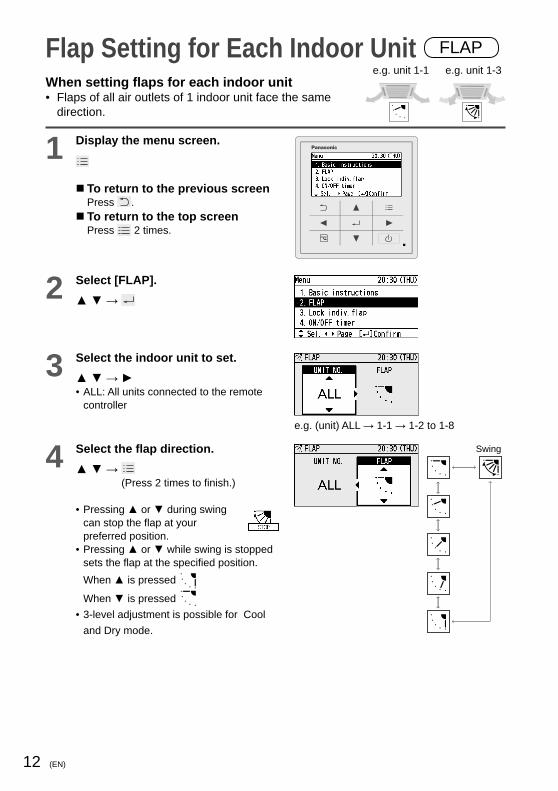
Flap Setting for Each Indoor Unit FLAP
When setting fl aps for each indoor unit• Flaps of all air outlets of 1 indoor unit face the same
direction.
1 Display the menu screen.
To return to the previous screenPress . To return to the top screenPress 2 times.
2 Select [FLAP].▲ ▼ →
3 Select the indoor unit to set.▲ ▼ → ►• ALL: All units connected to the remote
controller
e.g. (unit) ALL → 1-1 → 1-2 to 1-8
4 Select the fl ap direction.▲ ▼ →
(Press 2 times to fi nish.)
• Pressing ▲ or ▼ during swing can stop the fl ap at your preferred position.
• Pressing ▲ or ▼ while swing is stopped sets the fl ap at the specifi ed position.When ▲ is pressed
When ▼ is pressed • 3-level adjustment is possible for Cool
and Dry mode.
Swing
e.g. unit 1-1 e.g. unit 1-3

13(EN)
Flap Setting for Each Air Outlet Lock indiv. fl apWhen setting the fl ap for each air outlet individually according to the room condition• Even if the fl ap setting of all indoor units (P.9) or each indoor unit (P. 12) is
changed, the fl ap directions set here are not changed.
1 Display the menu screen.
To return to the previous screenPress . To return to the top screenPress 2 times.
2 Select [Lock indiv. fl ap].▲ ▼ →
3 Select the indoor unit to set.▲ ▼ → ►e.g. 1-1 → 1-2 to 1-8
4 Select the air outlet.▲ ▼ → ►• The air outlet No. changes according to
the installation direction. Check by actual operation.
1
2
3
4
5 Select the fl ap direction.▲ ▼ →
(Press 2 times to fi nish.)
• Although is also displayed in Cool and Dry mode, the actual direction is .
* For types other than the 4-way cassette type, the following display appears and this function cannot be used.
Swing
Unlock

14 (EN)
Timer Reservation ON/OFF timerThis turns ON/OFF at the specifi ed time. (e.g. Turning ON/OFF after 3 hours)
ON OFF
3 hours
OFF ON
Set 3 hoursOperation stop
Operation stop
Set Set
• Use OFF timer for example when: Reducing electric consumption while sleeping• Use ON timer for example when: Operating the air conditioner according to the
meeting start timing
1 Display the menu screen.
To return to the previous screenPress . To return to the top screenPress 2 times.
2 Select [ON/OFF timer].▲ ▼ →
3 Select the timer type▲ ▼ → • Select [OFF timer] or [ON timer].
4 Select [Set].▲ ▼ → • To set the timer to OFF, select [Unset].
5 Set the time.hour minute▲ ▼ → ► → ▲ ▼ →
→ (Press 2 times to fi nish.) • Upper limit: Stops in 72 h.
(by the 30 minutes)
Note If ON timer and OFF timer are set to the same time, priority is given to OFF timer, and ON timer cannot be used.

15(EN)
Timer Reservation Weekly timer overviewYou can set a weekly operation schedule.• The operation ON/OFF schedule or temperature setting schedule can be set by
setting the day and time (e.g. Setting the operation start time to 8:00 a.m. from every Monday to Friday.).
How to set (Overview)
(See P.16 for setting procedure)
• Select “Day”
• Select “Time”* Select “Operation”• Select “Temperature”
(Only for operations other than ON/OFF)
*Operation • ON: Starts operation with the temperature set last.• OFF: Stops operation.• ON & TEMP: Starts operation with the specifi ed temperature.• TEMP: Sets the temperature to the specifi ed temperature during
operation.
Combination examples 1. Stop operation earlier on “No-overtime work day”
8:00 17:00
8:00 22:00
ON
ON
OFFON
Weekday
No-overtime work day
• The setting registered for 1 day can be copied to other days. (P.19) 2. Set the temperature higher after the fi xed time.
8:00 22:0017:00
ON (26 °C) (28 °C)
ON & TEMP OFFTEMP
3. Stop operation during lunch break.8:00 22:0012:4512:00
ON ONOFF
OFF OFFON ON
4. This Thursday is a holiday.The timer can be disabled only for the specifi ed days with the registered schedules kept. (P.16)• Disable ( ) the timer of the specifi c Thursday which falls on
a holiday. • Enable ( ) the timer after the holiday is over.

16 (EN)
Timer Reservation Weekly timerNew registration • e.g. Start operation with 26 °C at 10:00 a.m. on every
Sunday.
1 Display the menu screen.
To return to the previous screenPress . To return to the top screenPress 2 times.
2 Select [Weekly timer].▲ ▼ →
3 Enable the Weekly timer.▲ ▼ → ◄ ► → • Select the item with ▲▼ and select [ ]
(enable)/[ ](disable) with ◄ ►.
4 Select [ ] for all days when the timer is used.◄ ► → ▲ ▼ →
(Repeat)• Select the days with ◄ ► and select [ ]
(enable)/[ ] (disable) with ▲ ▼.
5 Select the day for the timer setting.◄ ►
6 Select the fi eld to register the timer setting.▲ ▼ → • Up to 8 settings are available for each
day.• After registration, the items are arranged
in time series automatically.

17(EN)
7 Set the start time for the timer operation.hour minute▲ ▼ → ► → ▲ ▼ →
• 0:00 to 23:59
8 Select the timer operation.▲ ▼ → • Types of timer operation
ON: Starts operation with the temperature set last.
OFF: Stops operation. ON & TEMP.: Starts operation with the
specifi ed temperature. TEMP.: Sets the temperature to the
specifi ed temperature during operation.
9 Set the temperature.▲ ▼ → (Only for operations other than ON/OFF)
10 Confi rm the setting content.Confirm and press .
(Press 2 times to fi nish.)
To register additionallyRepeat from step 6 without pressing .
To copy the setting content to other days (P.19)
To set the timer to OFFStarting with step 1, select [-] in step 3 and press 2 times.
To set the timer to OFF for specifi ed days after registration(national holidays, etc.)Starting with step 1, set [-] for OFF days in step 4 and press 2 times.

18 (EN)
Timer Reservation Weekly timer continued
Change/Delete
1 After steps 1 to 4 on page 16, select the day to change or delete.◄ ►
2 Select the schedule to change or delete.▲ ▼ →
3 Select [Change] or [Delete].▲ ▼ →
4 Perform [Change] or [Delete] as follows.• To change the setting, following
steps 7 to 10 on page 17, set the time, timer operation and temperature and confi rm the content.
• To delete the setting, select [YES].◄ ► → →
(Press 2 times to fi nish.)
To change or delete settings repeatedly: Repeat from step 1 without pressing .
Note To delete all schedules of selected days
1 Select the day in step 1 above and press .
2 Select [Delete all: ] with ▲ ▼ and press .
3 Select [YES] with ◄ ► and press .

19(EN)
Timer Reservation Weekly timer continued
Timer copy The registered schedule can be copied to other days. This is convenient to apply the same schedule to multiple days.
1 Display the menu screen.
To return to the previous screenPress . To return to the top screenPress 2 times.
2 Select [Weekly timer].▲ ▼ →
3 Select [Timer copy].▲ ▼ →
4 Select the copy source day.◄ ► →
5 Select [ ] for all copy target days.◄ ► → ▲ ▼ → • Select the days with ◄ ► and select [ ]
with ▲▼.• [ ]: Copy source
6 Select [YES]. ◄ ► → →
(Press 2 times to fi nish.)

20 (EN)
Filter Information
1 Display the menu screen.
To return to the previous screenPress . To return to the top screenPress 2 times.
2 Select the item to set.▲ ▼ →
Filter information
3 Select [Next fi lter cleaning time].▲ ▼ →
4 Confi rm the operation time to the next cleaning.
(Press 2 times to fi nish.)
When cleaning is immediately necessaryThe screen shown on the right is displayed. Clean the fi lter.(See operating instructions of the indoor unit.) After the fi lter is cleanedSelect [Filter sign reset] in step 3 above and select [YES].◄ ► → →
(Press 2 times to fi nish.)
(The fi lter cleaning time count is reset.)

21(EN)
Note Depending on the model, [Filter info] cannot be used. In this case, a message is displayed as shown on the right.
When the cleaning time comes, the icon shown on the right appears on the top screen.

22 (EN)
Quiet Operation/Power Consumption Monitor
1 Display the menu screen.
To return to the previous screenPress . To return to the top screenPress 2 times.
2 Select the item to set.▲ ▼ →
Quiet operation
3 Enter the password.▲ ▼ → ► →
(Repeat)
4 Set [Select enable/disable] to [ ].▲ ▼ → ◄ ►• Select the item with ▲ ▼ and select [ ]/
[ ] with ◄ ►.
5 Select [Quiet time].▲ ▼ →
6 Set the time to perform quiet operation.▲ ▼ → ► → → (Repeat) (Press 2 times
to fi nish.)

23(EN)
Power consumption monitor
3 Select the period to display.▲ ▼ →
4 Confi rm the information. (Press 2 times to fi nish.)
Note
Depending on the model, [Quiet operation] and [Power consumption monitor] cannot be used. In this case, a message is displayed as shown on the right.
Using the quiet operation function may deteriorate the performance to reduce the operation sound.
The power consumption shows an approximate calculation result, which may differ from the measurement result calculated by a power meter.
• Pressing ◄► can switch data of 1-week total and data of each day.
• Pressing ◄► can switch data of 1-year total and data of each month.
• 1 day
Power consumption (approx.)
• 1 week
Power consumption (approx.)
• 1 year
Power consumption (approx.)

24 (EN)
Energy Saving ECONAVI
This function is available by attaching an optional ECONAVI sensor.The ECONAVI sensor detects human activity and conserves energy based on the activity level.
Overview of the ECONAVI function
High activity• Cooling: Target temperature is the same as the set temperature.• Heating: Target temperature is 1 °C lower than the set
temperature.
Low activity• Cooling: Target temperature is 1 °C higher than the set
temperature.• Heating: Target temperature is the same as the set temperature.
No one in the room No one in the room for 20 minutes• Cooling: Target temperature is 2 °C higher than the set
temperature.• Heating: Target temperature is 2 °C lower than the set
temperature.No one in the room for 3 hours• Cooling: Cooling will stop and the unit will be in fan only mode.• Heating: Heating will stop and the unit will be in fan only mode.
* When the sensor detects movements in the room which have been empty, it will resume operation to match with the activity level.
Note Even when target temperature is changed through the ECONAVI function, the set temperature shown in the remote controller does not change. Even when Cooling/Heating is changed to Fan through the ECONAVI function, the operation mode shown in the remote controller will still be Cooling/Heating. It is possible to choose from the following options for the operation to be performed after a lapse of 3 hours since the room has been empty.• Operates in the Fan mode only.• Stops and resumes operations after human movements are detected.• Stops and will not resume operations even after human movements are detected.• Continues to operate in the current mode.If you need to do so, please contact the dealer.

25(EN)
Note Turn the ECONAVI function OFF if:- You want to maintain the room temperature at a set temperature.- You want to keep air conditioner running while nobody is in a room.- The sensor fails.- Only infants, babies, or people only with disabilities are in the room. Depending on the model, [ECONAVI] cannot be used. In this case, a message is displayed as shown on the right.
WARNING
Do not use the ECONAVI function in a room with disabled persons or infants only. Due to their limited motions, the ECONAVI sensor may judge no person is present, causing the indoor unit to stop the operation.
1 Display the menu screen.
To return to the previous screenPress . To return to the top screenPress 2 times.
2 Select [Energy saving].▲ ▼ →
3 Select [ECONAVI] and set to [ ].▲ ▼ → ◄ ► →

26 (EN)
Energy Saving Temp auto return
Restoring the changed temperature to the originally set temperature automatically after a specifi ed time elapses. (e.g. Only when a guest comes)
Temp rangeRestricting the temperature range that can be set. (Temperatures outside the range cannot be set.)
1 Display the menu screen.
To return to the previous screenPress . To return to the top screenPress 2 times.
2 Select [Energy saving].▲ ▼ →
3 Select the item to set.▲ ▼ →
Temp auto return
4 Select the item and set to [ ].▲ ▼ → ◄ ► →
To operate only when energy can be savedSelect [Return type] with ▲ ▼ and select [Saving] with ◄ ►.
5 Set the time to return to the set temperature.▲ ▼ → (10 to 240 min: by the 10 min)
6 Set the temperature.▲ ▼ → →
(Press 2 times to finish.)
To set in series Repeat from step 4 without pressing .

27(EN)
Temp range
4 Select the item and set to [ ].▲ ▼ → ◄ ► →
5 Set the temperature range.▲ ▼ → ► → ▲ ▼ → →
(Press 2 times to fi nish.)Setting range• Cool/Dry: 18 °C to 30 °C• Heat: 16 °C to 30 °C• Auto: 17 °C to 27 °C
To set in series Repeat from step 4 without pressing .
Note
Temp auto returnWhen [Return type] is set to [Saving], this functions only when the temperature set in step 5 saves more energy than the changed temperature.e.g. When Cool 26 °C is set and the temperature is changed to 28 °C
• [Saving]: Keeps 28 °C • [Normal]: Returns to 26 °C
The temperature range that can be set varies depending on the model.

28 (EN)
Energy Saving Auto shutoff
When the operation is stopped at a specifi ed time (e.g. closing time) and resumed afterwards, this function detects the operation status at regular time intervals and stops operation automatically.Detect the operation status at regular time intervals and stop the operation automatically.(e.g. 60 min)
ON
OFF
21:00 22:08
Detect Detect Detect
23:00 9:00
60 min 60 min 60 min
Closing time Opening time
Auto shutoff in effect
Leaves the shop without turning off A/C.
If operation is detected... automatically stops.
Returns to get something left behind and turns on A/C
Auto stop
1 Display the menu screen.
To return to the previous screenPress . To return to the top screenPress 2 times.
2 Select [Energy saving].▲ ▼ →
3 Select [Auto shutoff] and set to [ ].▲ ▼ → ◄ ► →
4 Select the item to set.▲ ▼ →

29(EN)
Stop timeTime to stop operation (Time when Auto shutoff is activated)
5 Set.hour minute▲ ▼ → ► → ▲ ▼ → →
(Press 2 times to fi nish.)
End timeTime when Auto shutoff stops
5 Set.hour minute▲ ▼ → ► → ▲ ▼ → →
(Press 2 times to fi nish.)
TimerTime interval to detect operation status after [Stop time]
5 Set.▲ ▼ → →
(Press 2 times to fi nish.)
• 10 min to 180 min(by the 10 min)
30 (EN)
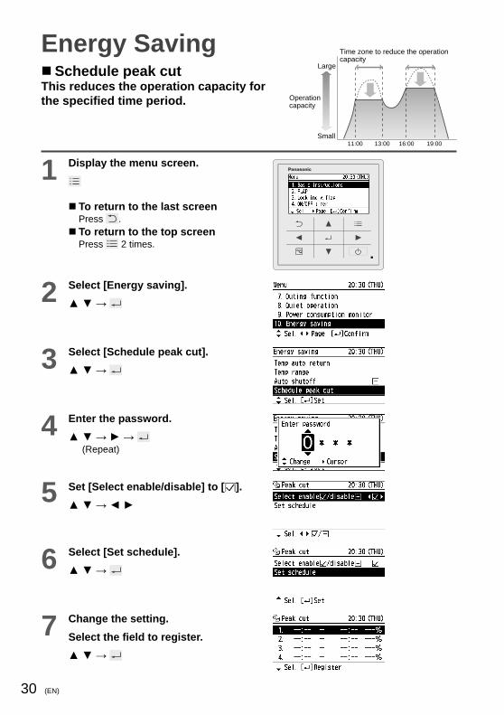
Energy Saving Schedule peak cut
This reduces the operation capacity for the specifi ed time period.
1 Display the menu screen.
To return to the last screenPress . To return to the top screenPress 2 times.
2 Select [Energy saving].▲ ▼ →
3 Select [Schedule peak cut].▲ ▼ →
4 Enter the password.▲ ▼ → ► →
(Repeat)
5 Set [Select enable/disable] to [ ].▲ ▼ → ◄ ►
6 Select [Set schedule].▲ ▼ →
7 Change the setting.Select the fi eld to register.▲ ▼ →
Large
Small11:00 13:00 16:00 19:00
Time zone to reduce the operation capacity
Operation capacity

31(EN)
8 Set the start time and end time.▲ ▼ → ► → ▲ ▼ →
(Repeat)
9 Select the operation capacity.▲ ▼ → →
(Press 2 times to fi nish.) To set in seriesRepeat from step 4 without pressing .
To change• Select the fi eld to change in step 7
above.
• Select [Change].▲ ▼ →
• Following the above steps 8 to 9, select the start time, end time and operation capacity.
To delete• Select the fi eld to delete in step 7
above.
• Select [Delete].▲ ▼ →
• Select [YES].◄ ► → →
(Press 2 times to fi nish.)

32 (EN)
Energy Saving Repeat off timer
This stops operation after a certain period of time each time operation is performed.(e.g. When forgetting turning off)
1 Display the menu screen.
To return to the previous screenPress . To return to the top screenPress 2 times.
2 Select [Energy saving].▲ ▼ →
3 Select [Repeat off timer] and set to [ ].▲ ▼ → ◄ ► →
4 Set the timer to stop.▲ ▼ → →
(Press 2 times to fi nish.)
• 10 min to 180 min(by the 10 min)
ON
OFF
60 min
Finishes working without turning off A/C.
Turns on A/C. Starts working.
Auto stop
(e.g. Setting to stop operation after 60 minutes)

33(EN)
Outing FunctionThis function prevents the room temperature from rising too high (or dropping too low) when no one is in the room due to outing, etc.
•
•
• •
•
•

34 (EN)
Outing Function1 Display the menu screen.
To return to the previous screenPress . To return to the top screenPress 2 times.
2 Select [Outing function]▲ ▼ →
3 Select [Select enable/disable] and set to [ ].▲ ▼ → ◄ ► →
4 Select [Set lower/upper limit temp.].▲ ▼ →
5 Set the temperature range.▲ ▼ → ► → ▲ ▼ → →
(Press 2 times to fi nish.)

35(EN)
Initial Settings Clock Clock type Operation lock
1 Display the menu screen.
To return to the previous screenPress . To return to the top screenPress 2 times.
2 Select [Initial settings].▲ ▼ →
3 Select the item to set.▲ ▼ →
Clock
4 Set the date and time.▲ ▼ → ► → → (Repeat)
Clock type
4 Select the type to display.▲ ▼ → →
(Press 2 times to fi nish.)
AM/PM
24 h
Operation lock
4 Select the type of lock and set to [ ].▲ ▼ → ◄ ► →
(Press 2 times to fi nish.)
To cancel lockSelect [-] in step 4. Only for [Lock all keys]Select [YES].◄ ► →
(Press 2 times to fi nish.)
36 (EN)
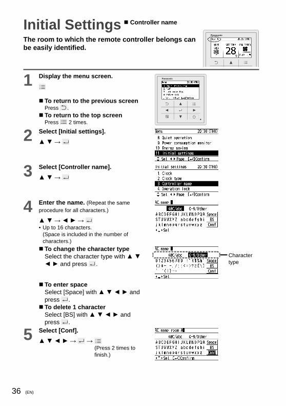
Initial SettingsThe room to which the remote controller belongs can be easily identifi ed.
1 Display the menu screen.
To return to the previous screenPress . To return to the top screenPress 2 times.
2 Select [Initial settings].▲ ▼ →
3 Select [Controller name].▲ ▼ →
4 Enter the name. (Repeat the same procedure for all characters.)
▲ ▼ → ◄ ► → • Up to 16 characters.
(Space is included in the number of characters.) To change the character typeSelect the character type with ▲ ▼ ◄ ► and press .
Character type
To enter spaceSelect [Space] with ▲ ▼ ◄ ► and press . To delete 1 characterSelect [BS] with ▲ ▼ ◄ ► and press .
5 Select [Conf].▲ ▼ ◄ ► → →
(Press 2 times to fi nish.)
Controller name
37(EN)
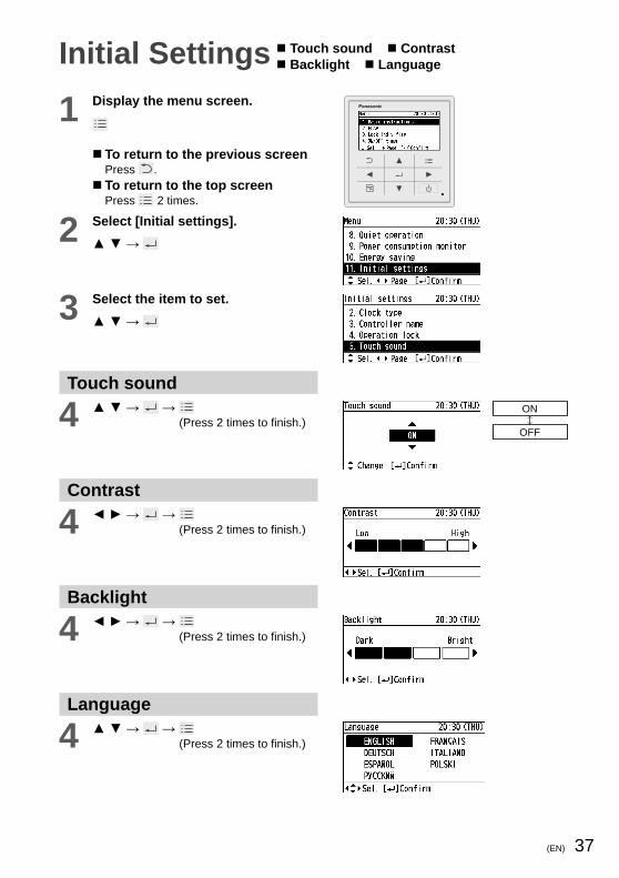
Initial Settings Touch sound Contrast Backlight Language
1 Display the menu screen.
To return to the previous screenPress . To return to the top screenPress 2 times.
2 Select [Initial settings].▲ ▼ →
3 Select the item to set.▲ ▼ →
Touch sound
4 ▲ ▼ → → (Press 2 times to fi nish.)
ON
OFF
Contrast
4 ◄ ► → → (Press 2 times to fi nish.)
Backlight
4 ◄ ► → → (Press 2 times to fi nish.)
Language
4 ▲ ▼ → → (Press 2 times to fi nish.)

38 (EN)
Initial Settings Password change Temp sensor Main/sub Vent output Contact address
1 Display the menu screen.
To return to the previous screenPress . To return to the top screenPress 2 times.
2 Select [Initial settings].▲ ▼ →
3 Select the item to set.▲ ▼ →
4 Enter the password as necessary.▲ ▼ → ► →
(Repeat)• Select the number with ▲▼ and move to
the next fi eld with ▶.
Password change
5 Enter a new password.▲ ▼ → ► →
(Repeat)
6 Enter the password again to confi rm.▲ ▼ → ► → →
(Press 2 times to fi nish.)

39(EN)
Temp sensor• Select the temperature sensor to
control the room temperature.
Temp sensor
Remote controller
Indoor unit
Main/sub• When 2 remote controllers are
connected to the same indoor unit, this registers one remote controller as [Main] and the other as [Sub]. (There is no difference in function between Main and Sub, however, when the remote controller sensor is selected for the temperature sensor setting, the [Main] sensor controls the operation.)
Vent output• [Set]: When the air conditioner is
turned ON/OFF, the connected ventilation fan is turned ON/OFF, too.
• To interlock the air conditioner and the fan, another installation work is required.
Contact address• If you need to contact for servicing,
check the back cover of the operating instructions for indoor units or outdoor units.
*To display each item, see steps 1 to 4 on the previous page.

40 (EN)
Ventilation Setting
1 Display the menu screen.
To return to the previous screenPress . To return to the top screenPress 2 times.
2 Select [Ventilation].▲ ▼ →
3 Select [Ventilation ON/OFF].
4 Select [ON] or [OFF].▲ ▼ → →
(Press 2 times to fi nish.)

41(EN)
Setting ListThis provides the meanings of setting information icons.
1 Display the menu screen.
To return to the previous screenPress . To return to the top screenPress 2 times.
2 Select [Setting list].▲ ▼ →
3 Select the item.▲ ▼ ◄ ► → • Only icons currently being displayed on
the screen are displayed here.
4 Confi rm.Confirm, then →
(Press 2 times to fi nish.)

42 (EN)
Setting information icon list
Icon Description Page
[Lock indiv. fl ap] is set. P.13
Switching between Heat and Cool/Dry mode is prohibited (Switching to Auto mode is also prohibited.). –
Remote control operation is restricted by a central control device. –
The indoor unit fi lter needs to be cleaned. P.20
The engine oil needs to be replaced (only when the gas heat pump air conditioner is used). –
[ON/OFF timer] is set. P.14
[Weekly timer] is set. P.15
Energy saving operation is in process. P.8
The operation capacity of the outdoor unit is restricted. –
[Schedule peak cut] is set. P.30
[Temp auto return] is set. P.26
[Temp range] is set. P.27
[Auto shutoff] is set. P.28
[Repeat off timer] is set. P.32
[Quiet operation] is set. P.22
The temperature sensor of the remote controller is detecting the room temperature. P.39
[Operation lock] is set. P.35
Fresh air is used for ventilation.(Only when connecting a heat exchange ventilation unit or connecting a commercially sold fan)
P.40
[Outing function] is set. P.33
Setting List

43(EN)
When the [Centrally controlled] message is displayed
Being centrally controlled, operation is not possible.
Blackout?
After recovery from blackout, press again. →If operation does not start, turn off the circuit breaker and consult the dealer of purchase about the symptom and Model No.
Is the circuit breaker turned off?
Turn it on and press again. →If operation does not start, turn off the circuit breaker and consult the dealer of purchase about the symptom and Model No.
Is [Assigning] blinking?
After blinking stops, press again. →If operation does not start, turn off the circuit breaker and consult the dealer of purchase about the symptom and Model No.
Is [ ] displayed?Alarm indication (e.g.)
Defective indoor unit No.
If any of the following alarm indications appears, stop operation once and restart approx. 1 minute later.(Alarm indication, off)[•E04 •E06 •P10 •P20 •H06] →If the indication does not reappear, use the unit. →If the indication reappears or an alarm indication other than the above (combination of numbers and characters such as E, F, H, L and P) appears, stop operation, turn off the circuit breaker and consult the dealer of purchase about alarm indication, Model No. and indoor unit No.
Cannot stop the operation.Or the unit starts to run automatically even if (Off) button is pressed.
Check if the outing function is activated or not. ( ) Check control by central control device.
TroubleshootingIf operation does not start by pressing ...Check the following before asking for repair.

44 (EN)
The remote controller screen displays a fl ashing “ ”.
Faulty sensor or incorrect installation. Turn OFF the ECONAVI function with the remote controller and contact the retailer or point of purchase with the Model No. and problem.
The remote controller screen does not display the
.
The indoor unit has stopped. Turn on the indoor unit. The unit is in Fan mode. The ECONAVI function does not operate in Fan mode. The ECONAVI function is set to OFF. Turn the ECONAVI function ON with the remote controller. The indoor unit may not support the ECONAVI function. If you turn the ECONAVI function ON with the remote control but there is no change, the indoor unit does not support the ECONAVI function.Please contact the dealer.
• If you need to contact for servicing, check the back cover of the operating instructions for indoor units or outdoor units.
Troubleshooting

45(EN)
Model No. CZ-RTC5
Dimensions (H) 120 mm x (W) 120 mm x (D) 16 mm
Weight 180 g
Temperature/Humidity range
0 ˚C to 40 ˚C / 20 % to 80 % (No condensation)*Indoor use only.
Power Source DC16 V (supplied from indoor unit)
ClockPrecision ± 30 seconds/month (at normal temperature 25 ˚C)
*Adjust periodically.
Holding time
72 hours (When fully charged)*Approx. 8 hours are required for full charge.
Number of connected indoor units
Up to 8 units
Specifi cations
© Panasonic Corporation 2015


![Index [] · 1 Index Company profile Company profile Air filter Urethane air filter / Mini collection Air filter Carburetor air filter Carbon fiber light-weight filter](https://img.dokumen.tips/doc/110x75/5adceab27f8b9aeb668c2bf7/index-index-company-profile-company-profile-air-filter-urethane-air-filter-.jpg)