Embed Size (px)
Citation preview
Operating and Maintenance Manual
AJAX BOILER INC.
Designed and Manufactured in Accordance with ASME Code Section IV, Heating Boilers
Photo shown may vary from actual model.
Model “DRF, WRF andWRF 30ppm NOx” Forced Draft Water Boiler (also known as DF & WF)
E.T.L. Listed
E.T.L. Canadian
Listed
c
ASME
ASME

AJAX BOILER INC. Page 2
Table of Contents Page
3 Operating and Installation Instruction 4 The Boiler Name Plate and Model Number 5 The Parts of the Boiler Exploded Boiler View Parts 6 Receiving your Boiler and Installation Code requirements Boiler placement Combustion air Venting Relief valve Check burner Stud nuts on boiler headers Water connections Gas connections Manual main gas shut-off valve Fuel oil connections Electrical Pump selection Expansion tank Indoor & outdoor boilers 9 Size of Piping to Gas Boilers Pipe delivery schedule Additional length of pipe to be added for each elbow or tee bend in the line 10 Installation Diagram – DRF Model 11 Installation Diagram – WRF & WRF-NOx Model 12 Installation with Refrigeration System 13 Water Treatment 14 Before Start-up Clean system Fill the boiler Fill oil tank Additional controls Venting Check factory assembled joints and head bolts 15 Start-up Instruction – Gas After start-up check list
Shutting down the boiler 17 Start-up Instruction – Oil
After start-up check list Shutting down the boiler
19 Maintenance Instruction Maintenance intervals
Removing and sealing the manway access door 25 Adjusting Gas Pilots on Power Flame C & J Burners 26 Trouble-shooting Guide Condensation Cold start-up Sooting 28 Quick Reference Guide Replacement parts Material Safety Data Sheet Contact Us Warranty Manufacturers Cut-Sheets (Disclaimer: Some parts may vary from actual model)

AJAX BOILER INC. Page 3
Operating and Installation Instructions (Model DRF, WRF, & WRF-NOx) Congratulations on your purchase of a new Ajax Boiler. In this book, we have included installation and maintenance instructions that, if followed, will provide you with many years of service from your boiler. Also included are instruction manuals for each of the controls furnished with the boiler. Please read them carefully. They should be helpful in both the installation and services of the boiler. Keep these instructions with the boiler for future reference. The Ajax water boiler is of rugged construction, yet of simple design. The boiler is of the inclined water tube type, consisting of two water headers with interconnecting, 2" O.D., straight inclined tubes. Normally, steel tubes are supplied on “closed” systems where the amount of make-up water is negligible. Copper tubes should be used on “raw” water applications, where a total or a high percentage of water make up takes place, or where water with high corrosive properties is encountered. The tubes are rolled and flared into tube sheets with a minimum 1/2" thick, P.V. quality steel plate. The boiler is equipped with removable head plates, front and rear, giving easy access to the straight tubes for inspection, cleaning or replacing. The combustion chamber and flue passages are designed to give maximum efficiency and serviceability. The best grade of castable refractory is used. Expansion joints are provided to allow for normal contraction and expansion of the refractory. The refractory is backed up with 3” of rockwool insulation. The boiler is enclosed in a casing of 18 gauge-galvanized steel. The boiler serial number is stamped on the front header plate and on the boiler nameplate, generally mounted on the right hand side of the boiler. All boilers furnished with copper tubes will have a decal applied on the front and rear head plates and will have sacrificial anodes fixed in the water box section of the head plates. Experience in the field has proven that the Ajax Boilers, if properly applied and maintained, will give many years of efficient, dependable and economical service. Ajax Boiler Inc. February 2007
AJAX BOILER INC. Page 4
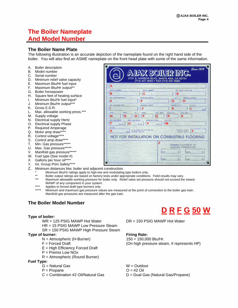
The Boiler Nameplate And Model Number The Boiler Name Plate The following illustration is an accurate depiction of the nameplate found on the right hand side of the boiler. You will also find an ASME nameplate on the front head plate with some of the same information. A. Boiler description B. Model number C. Serial number D. Minimum relief valve capacity E. Maximum Btu/Hr fuel input F. Maximum Btu/Hr output** G. Boiler horsepower H. Square feet of heating surface I. Minimum Btu/Hr fuel input* J. Minimum Btu/Hr output*** K. Gross E.D.R. L. Max. allowable working press.*** M. Supply voltage N. Electrical supply Hertz O. Electrical supply Phase P. Required Amperage Q. Motor amp draw**** R. Control voltage**** S. Control amp draw**** T. Min. Gas pressure***** U. Max. Gas pressure***** V. Manifold gas pressure***** W. Fuel type (See model #) X. Gallons per hour oil**** Y. Int. Group Prim Safety**** Z. Minimum distances btw. boiler and adjacent construction.
* Minimum Btu/Hr ratings apply to high-low and modulating type boilers only. ** Boiler output ratings are based on factory tests under appropriate conditions. Field results may vary. *** Maximum allowable working pressure for boiler only. Relief valve set pressure should not exceed the lowest
MAWP of any component in your system. **** Applies to forced draft type burners only ***** Minimum and maximum gas pressure values are measured at the point of connection to the boiler gas train.
Manifold gas pressures are measured after the gas train.
The Boiler Model Number
D R F G 50 W Type of boiler: WR = 125 PSIG MAWP Hot Water DR = 150 PSIG MAWP Hot Water HR = 15 PSIG MAWP Low Pressure Steam SR = 150 PSIG MAWP High Pressure Steam Type of burner: Firing Rate: N = Atmospheric (H-Burner) 150 = 150,000 Btu/Hr. F = Forced Draft (On high pressure steam, # represents HP) E = High Efficiency Forced Draft P = Premix Low NOx R = Atmospheric (Round Burner) Fuel Type: G = Natural Gas W = Outdoor P = Propane O = #2 Oil C = Combination #2 Oil/Natural Gas D = Dual Gas (Natural Gas/Propane)
B
A
C D
E F G H
I J K L
M N O P Q R S
T U V W
X Y
Z

AJAX BOILER INC. Page 5
The Parts of the Boiler Exploded Boiler View
Parts
1a Outer sheet metal jacket 7 Rear head plate 1b Rear jacket 8 Flue collector 1c Upper jacket panel 9,9a Firebox door, glass eye 2a-c Thermafiber 10 Frame 3a/b Thermotek Block 11 Galvanized floor 4a Header 12 Castable refractory 4b Waterbox 13 Kastite 4c Tubes 14 Refractory support 4d Head plate studs 5 Header gasket 16a-b Refractory 4e Head plate nuts 15 TCO panels 17,18 Low water probe , Pressure gauge 6 Front head plate 19,20 ASME data plate, Forced draft burner
See manufacturer’s cut-sheets enclosed with the boiler for complete information on the various parts.
AJAX BOILER INC. Page 6
Receiving your boiler And Installation Receiving your boiler Check Equipment Received: Inspect the boiler for any shipping damage. Make sure you have received all loose parts, such as draft hoods or controls packaged separately, which are listed on the packing slip. Note any damages or shortages on the bill of lading prior to signing it. If a boiler is received damaged or missing parts, it is your responsibility to notify the shipping company and file a freight claim. Ajax Boiler cannot send replacement parts for freight damaged or missing equipment as warranty items. Consignee must file claims for shortages and damages with the carrier. Permission to return goods must be received from the factory prior to shipping. Goods returned without a Returned Goods Authorization number will not be accepted. Purchased parts are subject to replacement only under the manufacturer’s warranty. The warranty does not include the cost of labor, removal, or installation of the warranted part. Installation Code Requirements: It is very important that your installation comply with all federal, state and local codes (NFGC, NEC, NFPA, CSD-1) as well as meet good industry practices as shown in publications issued by ASME, AGA, UL, ASHRAE, ABMA, ANSI etc. Boiler Placement: The boiler should be placed on a solid foundation, preferably a concrete pad, adequately sized for your boiler. Ajax Boilers are not suitable for installation on combustible surfaces. Electrical conduit should not be imbedded in the concrete directly under the boiler without first consulting with the engineer of the approved boiler pad. Provide adequate clearance for normal inspection and maintenance purposes and allow proper clearances for combustion air. Also, allow tube pull length clearance in the front or rear of the boiler for servicing (see boiler dimensions page for tube lengths). The minimum clearances to combustible surfaces are listed under the UL-795 clearance guidelines and on the boiler nameplate. Make sure the boiler is level, from side to side and front to back. Use metal shims if necessary.
Combustion Air: Adequate combustion air is one of the most important requirements for an atmospheric fired boiler. A lack of proper airflow can result in poor combustion, sooting and premature failure to the boiler. Sizing combustion air intakes according to the National Fuel Gas Code or NFPA 54 is acceptable. Ventilation openings should be provided per the National Fuel Gas Code. The boiler room should have two permanent openings. One opening shall be within two feet of the ceiling and one more within two feet of the floor. Each opening should have a free area of not less than 1 square inch per 1,000 BTU/HR of the total input of every combustion product in the boiler room. The openings should not be obstructed from the outside and air conditioning or exhaust fans should not interfere with proper airflow and ventilation of the boiler room. Consideration should always be given to the blocking effect of louvers in determining total free area. Always leave adequate clearance around the base of the boiler to allow the combustion air to freely enter the combustion chamber. The combustion air entering the boiler must be free of hazardous and flammable vapor fumes. This includes such fumes as perchlorethylene, chlorine, etc.
Venting: This particular boiler will produce positive and negative draft conditions as a result of the burner firing. All possible points of air infiltration or ex-filtration must be sealed. If the unit is to be fired under positive combustion chamber conditions, extreme care must be taken to ensure that a 100% seal is maintained. Please consult with a stack specialist for use of appropriate stacking material. Before attaching the breeching or extending the stack, be sure there are no obstructions or foreign materials in the vent or on the tubes of the boiler. The boiler should be vented as directly as possible. The stack must be the same diameter as the boiler vent or the combined area of multiple boiler vents. The recommended upward slope of the horizontal breaching is 1” per linear foot. In other words, the stack should rise 1” vertically for each foot horizontally. The stack should reach at least 3 feet above the highest obstruction of the roof to insure proper venting. The stack must be equipped with an appropriate
AJAX BOILER INC. Page 7
weather cap of the correct size. At no time should the boiler support the stack weight. (Refer to the latest version of the National Fuel Gas Code for additional installation requirements).
When a draft inducer is required, a draft proving switch must be wired to the boiler to prevent the boiler from firing unless the draft is proven.
Relief Valve: The relief valve discharge must be piped to a floor drain to eliminate the potential of scalding burns. The drain line must be the same size as the relief valve outlet and have a downward slope to insure proper drainage. The drain line termination should be visible to see discharge. Check the relief valve nameplate. The boiler operating pressure cannot exceed that listed on the relief valve. Also, confirm the boiler does not exceed the maximum Btu rating on the relief valve.
Check Burner: Check the burner mounting bolts and tighten if loose.
Stud Nuts on Boiler Headers: During shipment, the head plate nuts may loosen. Tighten these if required to the torques specified later in this manual. After the boiler has been in operation for a few days, check and retighten the head plate nuts. Refer to Quick Reference Guide.
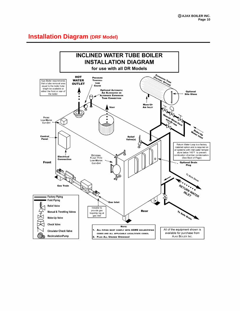
Water Connections: See typical piping diagram as shown in the installation instructions (page 10).
Gas Connections: Check supply gas pressure and select gas line pipe size for adequate capacity at boiler firing rate. Install a condensate trap in the gas line ahead of the boiler gas valve regulator. Do not use Teflon tape on the gas line pipe threads. Use a pipe compound rated for use with gas. All gas piping must be leak tested after installation as components may work loose during shipment. Do not check for gas leaks with an open flame. Use a bubble test. Do not test the boiler gas piping at a pressure higher than the boiler maximum gas pressure rating as this can damage the gas train components. Support the gas piping with hangers, not by the boiler or its accessories. Manual Main Gas Shutoff Valve: This valve is located on the upstream of the main gas pressure regulator and is normally located on the lower right side of the boiler. The gas supply is to be connected to this valve. Boilers with a minimum input rating are set for the specified rating at the factory. The minimum input rating is not adjustable in the field.
Fuel Oil Connections (Where applicable): Use copper tubing with flare fittings or iron pipe on all installations. All units must utilize the proper size and type of suction line oil strainers. Do not install manual valves in the return line between the pump and the tank unless required by a specific code. The fuel tank should be mounted above the pump level. If not, a two-pipe system is recommended. A check valve should be installed at the burner and a foot valve is recommended on the suction line within the fuel tank. These are installed to prevent the loss of oil supply, which can be damaging to the pump. It is recommended that prior to installation, MFPA-31 and all other national, state and local codes be followed. The size of the oil feed pipe depends on the length of line and whether the system is gravity or suction feed. (Please see the burner manual for oil line sizing). All lines should be tested for leaks after they have been installed. This should be done prior to running oil through them. The suction line should pass a vacuum test before placing oil in the tank. Plugging the tank end of the suction line may do this and connecting a vacuum gauge, valve and vacuum pump to the suction line stub in the boiler room. Air should be exhausted from the suction line until the vacuum gauge reads 24" of mercury (this figure is based on sea level conditions; for higher altitudes, corresponding lower values may be used). The valve should then be closed tightly and the test equipment should be allowed to stand for 24 hours, during which time, the gauge pressure should not decrease by more than ½ inch.
AJAX BOILER INC. Page 8
Electrical: The boiler is wired for 120volts 60hz 1phase and 12 amps, unless otherwise noted on the boiler nameplate. Verify the electrical supply using a voltmeter. The voltage tie-in leads are indicated on the wiring diagram. For your safety, turn off electrical power supply at the service entrance before making any electrical connections. This boiler contains sensitive control components and should be protected by a suitable commercial grade surge protection device and properly grounded. The boiler must be installed in accordance with the National Electric Code and in accordance with all state and local codes. Pump Selection: An appropriate sized pump will need to be installed, to pump water through the boiler at its appropriate flow rate. Ajax recommends using a delta T of 20° to 40°F through the boiler. The boiler circulation pump must interlock with the boiler, so the pump will operate under normal boiler operation.
Expansion Tank: A properly sized expansion tank is required on the boiler-piping loop.
Indoor Boilers: Protect all electrical components from moisture. The venting must be completely sealed to prevent spent flue gas into the boiler room. The draft diverter must be installed on top of metal screws in the boiler vent(s) per U.L. requirement. Note: Boilers are not designed to support stack weight.
Outdoor Boilers: The boiler must not be installed under any overhang that is less than 6 feet from the top of the boiler. Outdoor boilers have been tested to light off in 40 MPH and operate in 10 MPH wind conditions. Boiler must be protected from excessive wind and or down draft conditions (see venting). Three sides must be open in the area under the overhang. All roof water drainage must be diverted away from the boiler. Outdoor forced draft boilers require vent piping with an approved rain cap.
AJAX BOILER INC. Page 9
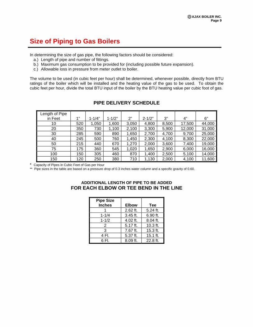
Size of Piping to Gas Boilers In determining the size of gas pipe, the following factors should be considered:
a.) Length of pipe and number of fittings. b.) Maximum gas consumption to be provided for (including possible future expansion). c.) Allowable loss in pressure from meter outlet to boiler.
The volume to be used (in cubic feet per hour) shall be determined, whenever possible, directly from BTU ratings of the boiler which will be installed and the heating value of the gas to be used. To obtain the cubic feet per hour, divide the total BTU input of the boiler by the BTU heating value per cubic foot of gas.
PIPE DELIVERY SCHEDULE
Length of Pipe in Feet
1”
1-1/4”
1-1/2”
2”
2-1/2”
3”
4”
6”
10 520 1,050 1,600 3,050 4,800 8,500 17,500 44,00020 350 730 1,100 2,100 3,300 5,900 12,000 31,00030 285 590 890 1,650 2,700 4,700 9,700 25,00040 245 500 760 1,450 2,300 4,100 8,300 22,00050 215 440 670 1,270 2,000 3,600 7,400 19,00075 175 360 545 1,020 1,650 2,900 6,000 16,000
100 150 305 460 870 1,400 2,500 5,100 14,000150 120 250 380 710 1,130 2,000 4,100 11,600
* Capacity of Pipes in Cubic Feet of Gas per Hour ** Pipe sizes in the table are based on a pressure drop of 0.3 inches water column and a specific gravity of 0.60.
ADDITIONAL LENGTH OF PIPE TO BE ADDED FOR EACH ELBOW OR TEE BEND IN THE LINE
Pipe Size Inches
Elbow
Tee
1 2.62 ft. 5.24 ft. 1-1/4 3.45 ft. 6.90 ft. 1-1/2 4.02 ft. 8.04 ft.
2 5.17 ft. 10.3 ft. 3 7.67 ft. 15.3 ft.
4 Fl. 5.37 ft. 15.1 ft. 6 Fl. 8.09 ft. 22.8 ft.
AJAX BOILER INC. Page 10
Installation Diagram (DRF Model)
AJAX BOILER INC. Page 11
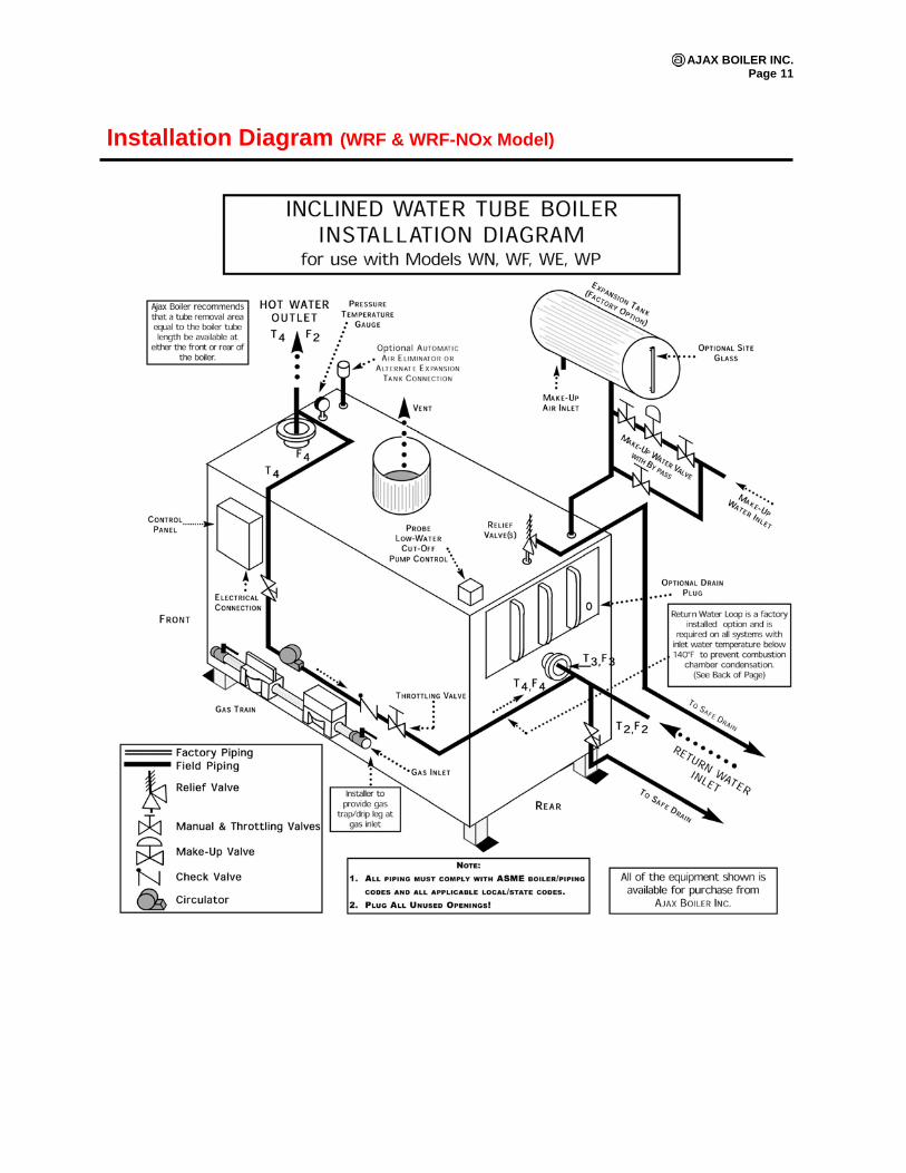
Installation Diagram (WRF & WRF-NOx Model)
AJAX BOILER INC. Page 12
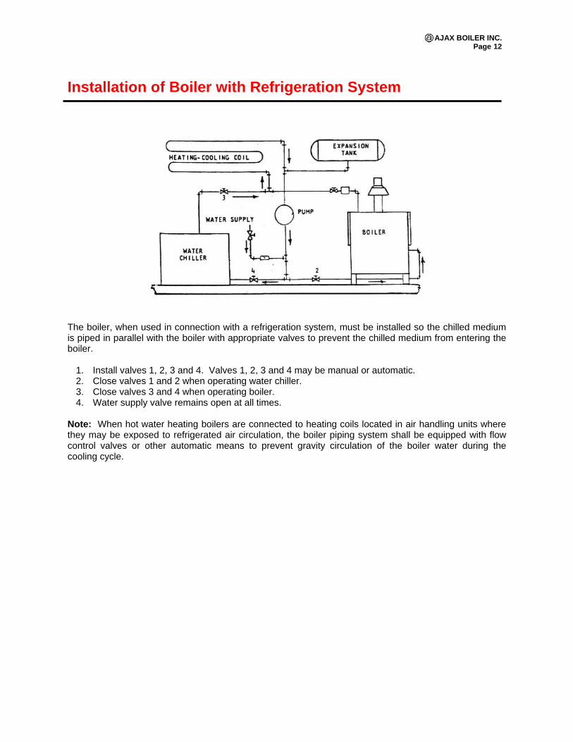
Installation of Boiler with Refrigeration System The boiler, when used in connection with a refrigeration system, must be installed so the chilled medium is piped in parallel with the boiler with appropriate valves to prevent the chilled medium from entering the boiler.
1. Install valves 1, 2, 3 and 4. Valves 1, 2, 3 and 4 may be manual or automatic. 2. Close valves 1 and 2 when operating water chiller. 3. Close valves 3 and 4 when operating boiler. 4. Water supply valve remains open at all times.
Note: When hot water heating boilers are connected to heating coils located in air handling units where they may be exposed to refrigerated air circulation, the boiler piping system shall be equipped with flow control valves or other automatic means to prevent gravity circulation of the boiler water during the cooling cycle.

AJAX BOILER INC. Page 13
Water Treatment We, the manufacturer of your boiler, wish to call to your attention to the necessity for a sound approach to the broad problem of boiler feed water treatment. Boilers used for space heating purposes only, operate with a closed system of piping in which all of the boiler water is brought back to the boiler. Under these conditions, very little raw makeup water is added to the system. Unless there are system leaks, only a small amount of makeup is required and there is little need for attention to the problem of feed water treatment. Heating boilers are subject to idle periods during the warmer months of a year. Protection of such idle boilers to prevent corrosion should be considered. Such protection can be provided in several ways and can be recommended by a qualified feed water treatment service or chemical supply company in your area. Makeup water continuously introduces contaminants; scale forming solids, corrosive minerals and oxygen, which is the primary cause of corrosion, in both water and steam boilers. The application of your boiler system, the condition of your boiler system and its operation should be carefully considered. For example, during initial operating periods of a new or a remodeled boiler system, all or a large amount of the water may be wasted. There are other reasons for water losses such as piping leaks, a faulty relief valve, blow down, summer drainage, etc. Whenever appreciable amounts of raw makeup water are continuously added to your system, we recommend that the problem be brought to the attention of a qualified water consultant. Boiler water treatment means more than just scale prevention. It actually includes:
1. The kind and control of the chemical treatment. 2. A suitable method of regulating the preheating and pretreatment of raw water. 3. Regulating and the method of blow down of the boiler water in amounts proportionate to the raw
water makeup.
The treatment program maintains the boiler water concentration within safe and acceptable limits for longer boiler life and reduced maintenance. The feed water treatment is dependent upon the make-up water conditions. We, the manufacturer, offer the following general guidelines for water treatment. Refer to Quick Reference Guide. The analysis for and the supervision of this treatment and control can only be handled by a qualified operator, of your own or an outside chemical service that specializes in the field. Particular care is exercised in handling the water problems in large utility central station plants. Modern industrial boilers deserve comparable attention. All modern boilers, including the smaller industrial types, are designed with lower water storage content than was used many years ago. They operate at ratings above those employed on the boilers of yesterday. This is one of the reasons we draw your attention to the importance of the proper handling of the water problem. Water treatment is a specialized subject that we, as boiler manufacturers, are not qualified to carry on a water treatment service. We, therefore, recommend that a qualified feed water treatment service company be used to supervise all phases of the water problem that may be encountered in your installation. This service should be picked most carefully as the prevention of trouble costs far less than the cost of repairs to equipment that has been neglected. Final proof of any feed water treatment program is in the continued observation of its effectiveness on the waterside surfaces of the boiler. Regular internal inspection of the boiler, therefore, should become part of the maintenance program.
AJAX BOILER INC. Page 14
Before Start-up
1. Clean system: The boiler and the entire system should be cleaned and flushed prior to filling the boiler.
2. Fill the boiler: a.) After cleaning, fill the system with a treated water mixture according to a water treatment
specialist’s recommendation and to the correct system pressure. Further information can be found at www.H2Ochem.com.
b.) To prevent the boiler from becoming air bound, open the relief valve located on the top rear of the boiler and leave it open until a steady flow of water is observed. On boilers equipped with a float type low water cut-off, the top cross in the low water cut-off piping should be opened to bleed off any air that may be trapped in the piping. Once this is done, close the relief valve, and low water cut-off assembly if applicable and complete filling the system to the correct pressure.
c.) After filling the system, inspect all piping throughout the system for leaks. If found, make necessary repairs.
3. Fill oil tank: Fill the oil tank with the proper grade of oil (If applicable, Models DRFO & DRFC). If
the fuel tank is below the burner level, be sure to prime the pump. If the oil pump is above the tank level, the pump should be lubricated to prevent damage by running dry. In some cases, the fuel pump may become air bound. To remove the air, remove the plug on the discharge side of the pump and run the burner until oil flows freely from the discharge. Afterwards, replace the plug and restart the burner.
4. Additional controls: Boilers are pre-wired at the factory. If additional controls are to be installed, care should be taken not to disturb the continuity of the existing circuit. Refer to the boiler wiring diagram and control manufacturer’s instructions supplied with the boiler.
5. Venting: The venting will include a barometric damper (draft hoods are not approved). A wind deflecting vent cap that prevents down drafts, must be securely fastened to the vent outlet. Outdoor units will be provided with a rain cap as standard.
6. Check factory assembled joints and head bolts: Although the boiler pressure vessel and the gas train are pressure tested prior to shipping, often times during shipment, items may work loose. These items may include head plate nuts, relief valves and gas train assemblies. These items should be checked prior to operating the boiler and tightened. Refer to Quick Reference Guide.
Important! The boiler gas piping and all connections should be tested for leaks before starting up the boiler. Do not use a flame test. It is important that you check the boiler gas train as some components may shift during transport. The boiler has been furnished completely assembled at the factory and furnished to deliver the rated capacity, as designated on the boiler nameplate. The manifold pressure must be set between the specified gas pressures recommended in the burner manual. The supply pressure to the boiler regulator must be set between the minimum and maximum pressures stated on the boiler nameplate.
AJAX BOILER INC. Page 15
Start-up Instructions – Gas Important! When starting up your boiler for the first time, run it at low fire for 30 minutes prior to running it at high fire. The refractory panels may contain moisture from the curing process. Running the boiler at low fire will dry out the panels. If the boiler is immediately operated at high fire, there may be a chance that the refractory will crack. A "cold" boiler should be treated the same way. Please see the burner operation manual for complete instructions.
1. Read manual: Before attempting to start-up the boiler, read this manual in its entirety and be familiar with the details contained within.
2. Verification: Locate the boiler nameplate and verify the voltage, type of gas, gas pressure and
regulator setting. Ensure free combustion air openings to the boiler room meet the requirements on the boiler nameplate, local codes, gas industry standards and the O&M manual. The venting will include a draft hood or barometric damper (Indoor units only). A wind deflecting vent cap that prevents down drafts, must be securely fastened to the vent outlet. Outdoor units will be provided with a rain cap as standard.
3. Inspect: Turn off all electric power and open the main gas valve. Smell for gas, especially around
the floor. If you smell gas, shut the main gas valve to the boiler immediately and check for piping leaks! If you do not smell gas, go on to the next step.
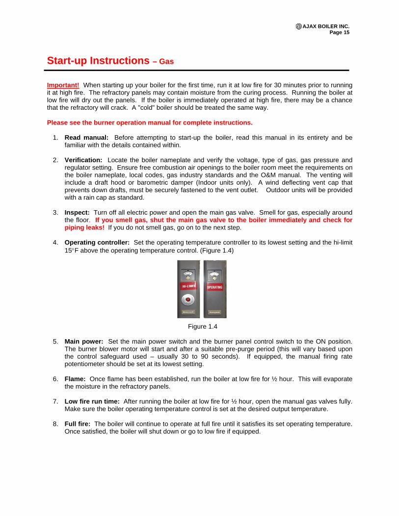
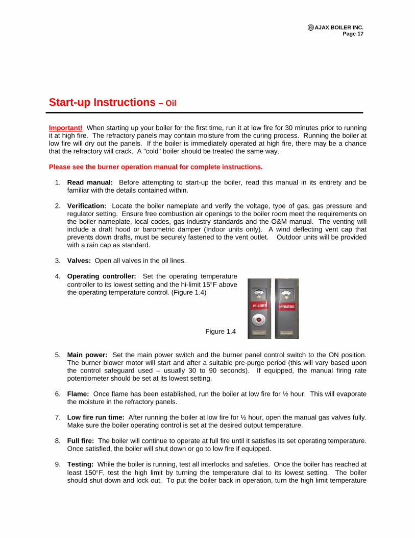
4. Operating controller: Set the operating temperature controller to its lowest setting and the hi-limit
15°F above the operating temperature control. (Figure 1.4)
Figure 1.4
5. Main power: Set the main power switch and the burner panel control switch to the ON position.
The burner blower motor will start and after a suitable pre-purge period (this will vary based upon the control safeguard used – usually 30 to 90 seconds). If equipped, the manual firing rate potentiometer should be set at its lowest setting.
6. Flame: Once flame has been established, run the boiler at low fire for ½ hour. This will evaporate
the moisture in the refractory panels. 7. Low fire run time: After running the boiler at low fire for ½ hour, open the manual gas valves fully.
Make sure the boiler operating temperature control is set at the desired output temperature. 8. Full fire: The boiler will continue to operate at full fire until it satisfies its set operating temperature.
Once satisfied, the boiler will shut down or go to low fire if equipped.
AJAX BOILER INC. Page 16
9. Testing: While the boiler is running, test all interlocks and safeties. Once the boiler has reached at least 150°F, test the high limit by turning the temperature dial to its lowest setting. The boiler should shut down and lock out. To put the boiler back in operation, turn the high limit temperature setting to 15°F higher than the operating temperature setting and press the reset button on the high limit. The boiler will now resume.
10. Testing low water cut-off: To check the low water cut-off, push the test button located on the
boiler control panel, labeled LWCO. Hold it for 5 seconds. This will produce a simulated low water shutdown. Upon release on the button, the boiler will remain locked out. The boiler will remain locked out until the low water cut-off reset button, located on the control panel, is depressed.
11. Draft: Stack Draft Requirements (FD), -0.02” to -0.04” Water Column.
12. Boiler Circulation: Proper water flow is required for water boilers; low water flow may cause
overheating of the water in the boiler tubes. Prolonged operation of the boiler under this condition may cause damage to the unit. The most common WARNING sign is a knocking sound, from which the water inside the boiler tubes is flashing to steam.
After Start-up Check List
Has air been purged from the system? Has the gas line piping been checked for gas leaks? Have the operating and high limit temperature controls been set? Is the boiler inlet water temperature above 140°F? Is the blow fan rotating in the appropriate direction? Flue gas spillage and soot: Check for spillage at the draft hood. Check for soot around the sheet
metal joints. Use the smoke from a match to detect flue gas spillage. If spillage is present, determine the cause of the problem and correct it.
Leaks: Look for water on the floor. Check for water leaks from any part of the boiler, valves or piping. Supports: Check for proper supports on the water piping and gas lines. Caution: Keep flammable materials away from the boiler. In the event of the boiler overheating –
shut the boiler down by (1) turning off the manual gas valve located in the gas controls manifold adjacent to the boiler and (2) turn off the electricity to the boiler.
Shutting Down the Boiler 1. Operating controller: Set the operating temperature controller to its lowest setting. 2. Burner: Follow the instruction in the burner manual for proper shutdown. 3. Power: Turn off the boiler by switching the toggle switch on the control panel into the OFF position. 4. Gas valves and oil line: Close the main gas valve and/or oil lines.
AJAX BOILER INC. Page 17
Start-up Instructions – Oil Important! When starting up your boiler for the first time, run it at low fire for 30 minutes prior to running it at high fire. The refractory panels may contain moisture from the curing process. Running the boiler at low fire will dry out the panels. If the boiler is immediately operated at high fire, there may be a chance that the refractory will crack. A "cold" boiler should be treated the same way. Please see the burner operation manual for complete instructions.
1. Read manual: Before attempting to start-up the boiler, read this manual in its entirety and be familiar with the details contained within.
2. Verification: Locate the boiler nameplate and verify the voltage, type of gas, gas pressure and
regulator setting. Ensure free combustion air openings to the boiler room meet the requirements on the boiler nameplate, local codes, gas industry standards and the O&M manual. The venting will include a draft hood or barometric damper (Indoor units only). A wind deflecting vent cap that prevents down drafts, must be securely fastened to the vent outlet. Outdoor units will be provided with a rain cap as standard.
3. Valves: Open all valves in the oil lines.
4. Operating controller: Set the operating temperature
controller to its lowest setting and the hi-limit 15°F above the operating temperature control. (Figure 1.4)
Figure 1.4
5. Main power: Set the main power switch and the burner panel control switch to the ON position. The burner blower motor will start and after a suitable pre-purge period (this will vary based upon the control safeguard used – usually 30 to 90 seconds). If equipped, the manual firing rate potentiometer should be set at its lowest setting.
6. Flame: Once flame has been established, run the boiler at low fire for ½ hour. This will evaporate
the moisture in the refractory panels.
7. Low fire run time: After running the boiler at low fire for ½ hour, open the manual gas valves fully. Make sure the boiler operating control is set at the desired output temperature.
8. Full fire: The boiler will continue to operate at full fire until it satisfies its set operating temperature.
Once satisfied, the boiler will shut down or go to low fire if equipped.
9. Testing: While the boiler is running, test all interlocks and safeties. Once the boiler has reached at least 150°F, test the high limit by turning the temperature dial to its lowest setting. The boiler should shut down and lock out. To put the boiler back in operation, turn the high limit temperature
AJAX BOILER INC. Page 18
setting to 15°F higher than the operating temperature setting and press the reset button on the high limit. The boiler will now resume.
10. Testing low water cut-off: To check the low water cut-off, push the test button located on the
boiler control panel, labeled LWCO. Hold it for 5 seconds. This will produce a simulated low water shutdown. Upon release on the button, the boiler will remain locked out. The boiler will remain locked out until the low water cut-off reset button, located on the control panel, is depressed.
11. Draft: Stack Draft Requirements (FD), -0.02” to -0.04” Water Column.
After Start-up Check List
Has air been purged from the system? Has the gas line piping been checked for gas leaks? Have the operating and high limit temperature controls been set? Is the boiler inlet water temperature above 140°F? Flue gas spillage and soot: Check for spillage at the draft hood. Check for soot around the sheet
metal joints. Use the smoke from a match to detect flue gas spillage. If spillage is present, determine the cause of the problem and correct it.
Leaks: Look for water on the floor. Check for water leaks from any part of the boiler, valves or piping. Supports: Check for proper supports on the water piping and gas lines. Caution: Keep flammable materials away from the boiler. In the event of the boiler overheating –
shut the boiler down by (1) turning off the manual gas valve located in the gas controls manifold adjacent to the boiler and (2) turn off the electricity to the boiler.
Shutting Down the Boiler 1. Operating controller: Set the operating temperature controller to its lowest setting. 2. Burner: Follow the instruction in the burner manual for proper shutdown. 3. Power: Turn off the boiler by switching the toggle switch on the control panel into the OFF position. 4. Gas valves and oil line: Close the main gas valve and/or oil lines.
AJAX BOILER INC. Page 19
Maintenance Instructions
1. Keep tubes clean: In order to maintain high boiler efficiency and boiler life, the boiler tubes should be cleaned periodically, both inside and outside. The frequency of cleaning the inside of the boiler tubes depends on the characteristics of the water and the type of installation. When a large amount of makeup water is used, it is good practice to inspect and clean, if necessary, the inside of the tubes after 30 days. The accumulation of lime and other solids within this time will establish the criterion for how often the boiler tubes should be cleaned. On closed systems, where only a small amount of makeup water is used, the insides the boiler tubes should be examined and if necessary, cleaned at the end of the heating season. When makeup water is negligible, such as boilers connected to unit heaters or radiators, the boiler should be flushed at the end of each heating season. All water boilers should have a tee installed at the boiler inlet for draining the boiler. Clean tubes will not only ensure higher boiler efficiency but will also prevent possible damage to the boiler. The boiler should never be fired unless it is full of water.
2. Gaskets: Tighten gaskets during start up and periodically thereafter. Leaky gaskets will cause the
use of excessive makeup water and could cause corrosion of the stud bolts. It is good practice to use a new gasket; however, if the gasket is not damaged, it may be reused. Use a soft gasket compound on both sides of the gasket. Specify boiler model number and the height and width of the boiler head plate when ordering new gaskets.
3. Studs: Keep studs protected from corrosion with paint or oil. Keep stud bolts tight to prevent leaky
gaskets. Stud bolts will not corrode if they are kept dry and protected. Use caution in removing and reinstalling head plates. The boiler must be shut down and drained. Before removing the nuts, apply penetrating oil and allow it to set for a few minutes. Tap the head plate lightly around each stud bolt before trying to break the nut loose. Forcing the nut off could cause breakage. Use a torch to heat the nut and it will come off easier. If a torch is not available, take a cold chisel, place it across the flat of the nut, and strike several sharp blows with a heavy hammer. This should loosen the nut. If necessary, it is better to split the nut open and replace it than to break the stud off.
Should, for any reason, a stud bolt on a boiler head be broken, it can be replaced as follows:
without removing the heat plate, use a slow speed drill to drill out the remaining portion of the stud. Re-drill the header and tap using a standard thread tap. Spare studs may be obtained from the factory.
4. Controls: Under normal conditions, controls furnished with the Ajax Boiler require very little
service. It is important, however, that the controls be protected from moisture and dirt. All controls should be checked frequently to make sure that they are working properly. Turn both the operating controls and the safety controls up and down to verify that they will operate satisfactorily. The high limit control furnished with the boiler should only be used as a safety control.
5. Power burner: Reference the maintenance and service instruction in the burner manual.
6. Relief valve: Boilers are equipped with a lever type relief valve of “ASME” rated capacity. To
maintain the valve in good working condition, it should be manually opened once a month on “closed” systems and once a week on “open” systems. The relief valve outlet should be piped directly to an open drain and the drain checked frequently for discharge. If the relief valve is leaking or does not operate freely, it should be replaced.
AJAX BOILER INC. Page 20
7. Low water cut-off: A low water cutoff is furnished to protect the boiler against damage by
preventing it from operating without water. This is particularly important when the boiler is installed above the water level, i.e., on a roof. Low water level cutoffs should be checked periodically by lowering the water level in the boiler and verifying that the safety circuit opens. Float type low water cutoffs should be flushed at least once a week on “open” systems and once a month on “closed” systems (if applicable). If neglected, accumulation of sediment within the low water cutoff casing may render the control inoperative and thereby become a safety hazard. Probe low water cutoffs may accumulate deposits on the grounding element. These should be carefully cleaned.
8. Operating control: The operating temperature control sets the desired boiler water temperature
output. To adjust the water temperature, insert a small straight screwdriver into the slotted screw hole at the front of the controller. This controller has an adjustable differential wheel under its casing.
9. High limit manual reset: The boiler is equipped with a manual reset high limit temperature safety
designed to shut down the boiler in the event the boiler water temperature exceeds the high limit set point. The high limit should be set 15°F above the operating temperature controller.
10. Gas pressure switches (Optional, where applicable): The low gas pressure switch is designed
to shut down the boiler if the gas supply drops below its set point. The high gas pressure switch is designed to shut the boiler down if the gas pressure exceeds its set point. Both switches will lock out and must be manually reset if tripped.
11. Anodes: Magnesium anodes are standard on all copper tube boilers. They will extend the life of
the boiler, and must be replaced periodically. The replacement frequency can vary from six months to several years. Higher temperatures and/or higher total dissolved solid contents in the boiler water will speed electrolysis and decrease the life of the anodes. Normally, two anodes in each header are adequate for header protection. Under adverse conditions, it may be necessary to install as many as three or four anodes in each header. New anodes may be purchased from your Ajax Boiler representative.
12. Venting system (indoor boilers): Examine the venting system externally at least once a year for:
a.) Tightness of all joints and connections including the draft hood to the boiler and the vent connection from the draft hood to the stack.
b.) Corrosion of metal in the vent ducting.
14. Flue gas passageways: Inspect and clean, if necessary, at least once every five years. a.) Shut off gas and turn off electric power to boiler. b.) Disconnect vent pipe and remove draft hood(s) or vent cap on outdoor boilers. c.) Examine flue gas passageways and the inside of the venting system for soot and corrosion. d.) If cleaning is needed, open front door, remove main burners, and cover burner orifices and
pilot burner with a waterproof covering. e.) Protect controls, electrical, etc. with waterproof covering. f.) Clean tube bundle through vent opening(s) at top of boiler using a water or steam hose.
Clean out and reassemble boiler after cleaning.
Note: If any parts need tightening or replacement, consult a qualified serviceman. It is highly recommended that an operator’s log be kept as a record of boiler readings as a way of tracking operational changes that may affect warranty and/or boiler reliability.
AJAX BOILER INC. Page 21
Maintenance Intervals Daily Maintenance
1. Check water level: An unstable water level can indicate several problems such as excessive solids or water treatment, contamination from oil, overload or control malfunction. Ensure there is water in the gauge glass (if applicable) every time you enter the boiler room.
2. Check combustion visually: Look at the flame to see if anything has changed. Changes may be an indication that a problem is developing.
3. Treat water according to the established program: Add chemicals and take tests as outlined by your chemical feed water consultant.
4. Record boiler operating pressure and temperature: An excessive steam or water temperature drop will alert you to excessive loading on the boiler.
5. Record feed water pressure and temperature: A change in pressure or temperature may indicate a problem is developing with your feed pump(s), deaerator or packaged feed system.
6. Record stack temperatures: Changes in stack temperatures could indicate the boiler is sooting, scaling or there is a problem with baffles or refractory.
7. Record oil-atomizing pressure (if applicable): Changes in pressure could have an effect on combustion in the boiler.
8. Record gas pressure: Changes in pressure could have an effect on combustion in the boiler and indicate a problem in the gas delivery system.
9. Check with general boiler/burner operation personnel: Has anything changed from the day before? If so, why?
10. Record boiler water supply and return temperatures: On hot water boilers, record these temperatures to assist in detecting system changes. Return temperatures below 140ºF will cause the boiler to condense.
11. Record makeup water usage: Excessive makeup water could be an indication of system problems (leaks) in both steam and hot water systems.
12. Check auxiliary equipment: There is a vast difference between "is it running" and "is it running properly." Take nothing for granted, as auxiliary equipment can shut down your operation.
Weekly Maintenance 1. Check for tight closing fuel valves: Check to ensure fuel does not flow through the fuel
valve(s) when the burner is shut off. 2. Check fuel and air linkage: Check to ensure that all set-screws on linkages are tight and
securely holding the linkage in place (Forced Draft boilers). 3. Check indicating lights and alarms: Check for burned out or loose light bulbs. In addition,
check to ensure the alarm bell sounds on the appropriate shut down condition. 4. Check operation of water level controls: Stop the boiler feed pump and allow the control to
stop the boiler under normal low fire conditions. 5. Check for leaks, noise, vibration, unusual conditions, etc.: Checking for these items, is a
cost-effective way to detect system operational changes. Small problems can be corrected before they become large problems.
6. Check operation of all motors: By developing a routine, any change in operation or bearing temperature will usually be caught in time to avoid a failure.
7. Check the flame scanner assembly (if applicable): Using the appropriate meter, check the flame signal strength at the program relay flame amplifier. Ensure the scanner assembly is clean and dry.
AJAX BOILER INC. Page 22
8. Check gauge glass: Ensure there are no scratches or etching in the glass or leakage around the package.
Monthly Maintenance 1. Inspect burner operation: Do a visual inspection of the pilot flame and main burner flame
throughout the firing range. 2. Analyze combustion: Take the flue gas analysis over the entire firing range, comparing the
combustion analysis and stack temperature reading with the pervious month. 3. Check cams (Power burners): Inspect the cam springs for scoring, tightness of set-screws,
free movement, alignment of cam followers and other related parts. 4. Check for flue gas leaks: Ensure something hasn't changed in the breaching, stack or overall
system that allows flue gas to be drawn into the boiler room. 5. Check boiler blow down: Review boiler blow down to determine that a waste of treated water
is not occurring. Check water treatment and testing procedures with your feed water consultant.
6. Check all combustion air supply inlets: Ensure sufficient combustion air is being supplied to the boiler room and burner.
7. Check all filter elements (oil, gas and air): Clean or replace as needed. On “self-cleaning” filters, make certain that impurities are flushed or discharged from filter body.
8. Check the fuel system: Make sure certain strainers, vacuum gauges, pressure gauges and pumps are properly cared for.
9. Check lubrication: Verify lubrication requirements of all bearing supported equipment. Do not over-lubricate electric motors.
Semi-Annual Maintenance 1. Clean low water cut-off(s): Remove the head assembly or probes, inspect and clean out any
sediment or contamination in the column or piping. Determine why sediment or contamination condition exists.
2. Pre-heaters: Check oil pre-heaters by removing the heating element and inspect for sludge or scale.
3. Repair refractory: Repair all cracks and fill in gaps. 4. Clean oil pump strainer and filter: Ensure they are not plugged, thus reducing the flow of the
required oil to the burner. 5. Reset combustion: The entire combustion process should be carefully checked, O2 readings
taken and necessary burner adjustments made. Make certain readings are recorded and used as a basis of comparison for future tests. Combustion adjustments should only be made by those thoroughly familiar with all aspects of burner adjustments and combustion.
Annual Maintenance 1. Clean fireside surfaces: Clean fireside surfaces by brush or use a powerful vacuum cleaner
to remove soot. After the cleaning process, and if the boiler is to be left open, it is advisable to spray all fireside surfaces with some type of corrosion preventative.
2. Clean breaching: Inspect breaching, stack, and remove any soot build-up. 3. Clean waterside surfaces: Remove all head plates and inspect tubes. Inspect water
columns, tee and float assemblies from water columns. Thoroughly wash all waterside surfaces.
4. Check gauge glass for possible replacement: If internal erosion at water level is noted, replace with new glass and gaskets.
5. Remove and recondition safety valves: Have them reconditioned by an authorized safety valve facility. The safety valve is an important device yet possibly receives less attention than any other device.
AJAX BOILER INC. Page 23
6. Boiler feed pumps: Strainers should be reconditioned. Feed-pump elements wear and must be replaced. Sometimes a review of the condensate return system and chemical feed arrangement will reveal causes of short pump life.
7. Chemical feed systems: Chemical feed systems should be completely emptied, flushed and reconditioned. Metering valves or pumps should be reconditioned at this time.
8. Tighten all electrical terminals: All terminals should be checked for tightness, particularly on starters and moveable relays.
9. Check linkages: Check to ensure the linkage ball connectors have not worn out. Worn connectors can cause inconstancy in the linkage movement and result in unrepeatable excess air levels in the combustion process.
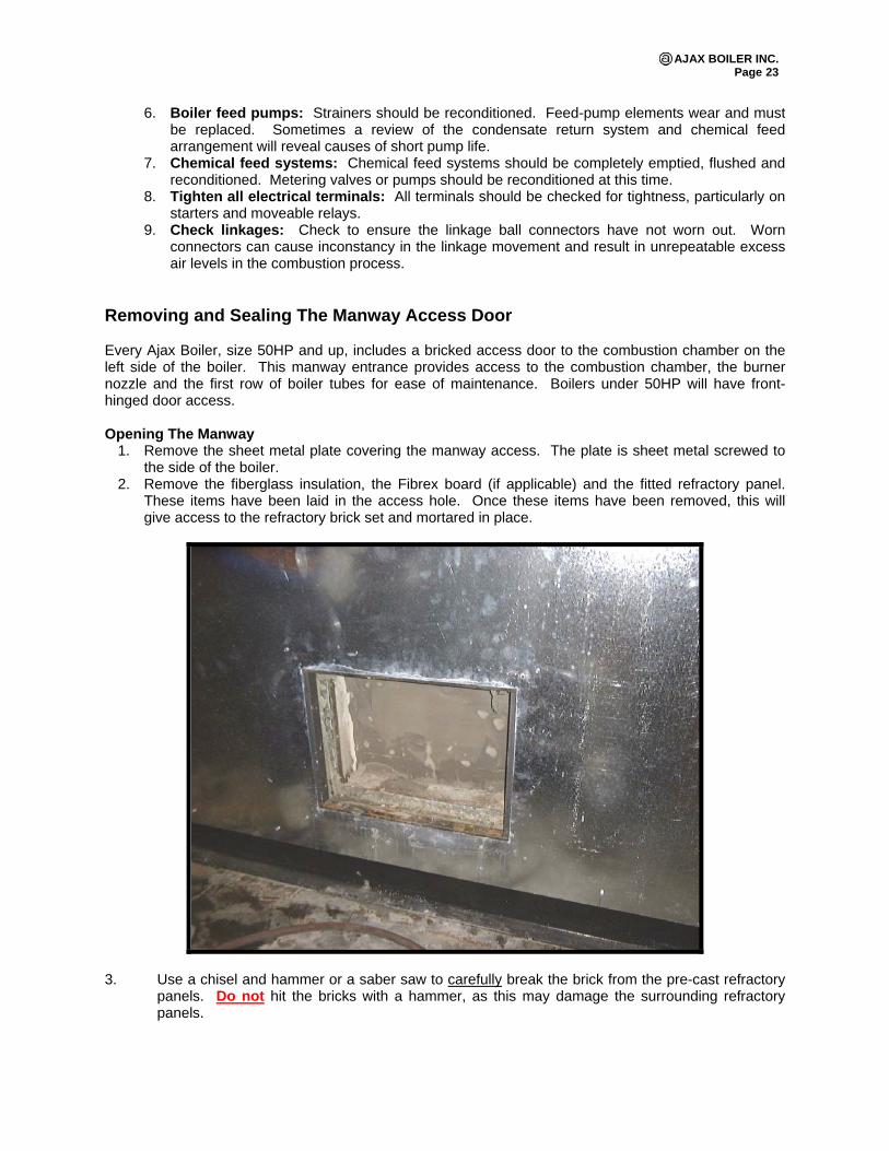
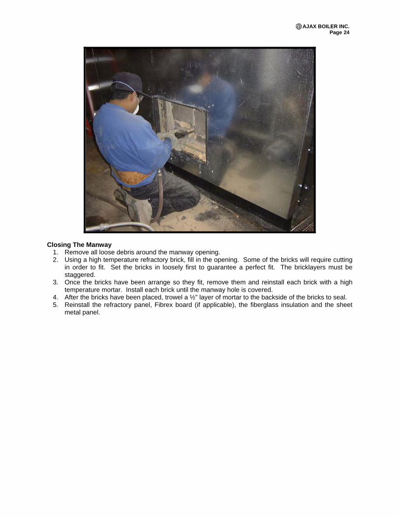
Removing and Sealing The Manway Access Door Every Ajax Boiler, size 50HP and up, includes a bricked access door to the combustion chamber on the left side of the boiler. This manway entrance provides access to the combustion chamber, the burner nozzle and the first row of boiler tubes for ease of maintenance. Boilers under 50HP will have front-hinged door access. Opening The Manway
1. Remove the sheet metal plate covering the manway access. The plate is sheet metal screwed to the side of the boiler.
2. Remove the fiberglass insulation, the Fibrex board (if applicable) and the fitted refractory panel. These items have been laid in the access hole. Once these items have been removed, this will give access to the refractory brick set and mortared in place.
3. Use a chisel and hammer or a saber saw to carefully break the brick from the pre-cast refractory panels. Do not hit the bricks with a hammer, as this may damage the surrounding refractory panels.
AJAX BOILER INC. Page 24
Closing The Manway 1. Remove all loose debris around the manway opening. 2. Using a high temperature refractory brick, fill in the opening. Some of the bricks will require cutting
in order to fit. Set the bricks in loosely first to guarantee a perfect fit. The bricklayers must be staggered.
3. Once the bricks have been arrange so they fit, remove them and reinstall each brick with a high temperature mortar. Install each brick until the manway hole is covered.
4. After the bricks have been placed, trowel a ½" layer of mortar to the backside of the bricks to seal. 5. Reinstall the refractory panel, Fibrex board (if applicable), the fiberglass insulation and the sheet
metal panel.
AJAX BOILER INC. Page 25
Adjusting Gas Pilots On Power Flame C & J Burners Scanner Pilot
1. Ensure gas pressure does not exceed pilot regulator specifications 2. Set pilot gas pressure at 1 ½" to 4" WC. Best flame signal at test tee on pilot. 3. Ensure there is an adequate earth ground. 4. Check for proper electrode gap and depth in pilot head. See Burner Manual. 5. Check for strong blue spark from ignition transformer. 6. Ensure air holes in pilot body are unobstructed. 7. Clean pilot electrode of soot. 8. Check for pilot pressure at main flame light off. If pilot pressure drops at the point when the main
gas valve opens, check for proper gas supply. Gas line may be undersized our under-pressured. 9. Adjust pilot to improve signal. 10. Check boiler draft. High draft may affect pilot reliability.
Flame Rod Pilot
1. Ensure flame rod is clean. 2. Make sure all grounding points on pilot are clean. 3. Check for proper electrode gap and depth in pilot head. See Power Flame Manual. 4. Check for strong blue spark from ignition transformer. 5. Flame sensing wire resistance should be near 0 ohms. 6. Ensure static inlet gas pressure does not exceed pilot regulator. 7. Set pilot gas pressure at 1 ½" to 4" WC. Best flame signal at test tee on pilot. 8. Check for pilot pressure at main flame light off. If pilot pressure drops at the point when the main
gas valve opens, check for proper gas supply. Gas line may be undersized our under-pressured. 9. Ensure air holes in pilot body are unobstructed. 10. Check the draft through the boiler in the off-cycle, pre-purge and pilot flame establishing pressure.
High draft will affect pilot reliability and can cause pilot failures. Reduce draft via barometric damper or other draft control device.
AJAX BOILER INC. Page 26
Trouble Shooting Guide The following is a list of items that can cause boiler performance problems if not installed correctly.
Available combustion air: Normal Conditions: 1 sq. in. open area per 1000 Btu/hr. Note: This must be open area between louvers. Stack draft: Normal Conditions: Forced Draft: Balanced draft, -0.02” to -0.04” WC. Combustion Chamber Pressure: The combustion chamber pressure should not exceed 0.25” WC on “DRF” boilers and should not exceed +0.50” WC on “DRF” boilers with lox NOx burners installed by factory. Fuel pressure: See Burner Manual. Inlet water treatment, flow, and/or temperature: Minimum inlet water temperature without boiler recirculator line = 140°F
The following are common problems with possible causes and solutions. 1. Nuisance flame failures: See Burner Manual. 2. Boiler not putting out enough heat: The main reason a boiler will not put out enough heat is
usually due to there not being enough gas reaching the burners. Check the following: a.) Have you been able to accurately measure the gas flow (oil) rate at the meter? b.) What is the gas pressure at the burner manifold? c.) What is the inlet gas pressure, while the burner is firing? This number will be lower than
when the burner is not firing? d.) Review combustion report, if the boiler is under fired, there should be too much Oxygen in the
stack gases? e.) Is the boiler at altitude? If yes, has it been derated?
4. Boiler is sooting up: a.) Condensate: Check the boiler's flue gas using a combustion analyzer and compare those to
the ideal combustion list. Refer to Ideal Combustion Rate. A high percentage of CO in the combustibles is an indication of a sooting problem. Running the boiler in a condensing mode with inlet water temperatures below 140°F. When this happens, it will “rain” down on the burners and appear to be leaking. The boiler will subsequently soot up.
b.) Insufficient gas/air ratios: See Burner Manual. c.) Check Start-up or Combustion report: d.) Combustion: Open a door to the boiler room. Any improvement? If so, there is not enough
combustion air in the boiler room. e.) Pressurization: Is the room pressurized? Is there other equipment in the room? Is there an
extractor fan in the room?
5. My boiler is leaking: Sometimes boilers appear to be leaking when they are actually operating in a condensing mode. To prevent condensing, inlet water temperature should be 140°F or higher.
AJAX BOILER INC. Page 27
Condensation During startup conditions, when the boiler water temperature is below 140°F, condensation will occur. Condensation will stop when the return boiler water temperature exceeds 140°F. Water tube boilers, including the Ajax Boiler, should not be operated at water inlet temperatures below 140°F. Prolonged operation of the boiler under condensation conditions will cause damage to the boiler. If the boiler application requires inlet water temperatures below 140°F, a boiler recirculation system must be installed so that the cold inlet water is mixed with hot boiler water in a ratio to ensure that condensation does not occur. Cold Start-ups Too many cold startups will be evidenced by rust stains on the refractory inside the boiler and around the boiler doors. If condensation occurs regularly, eventually the boiler tubes and firebox area may rust apart and collapse. Frequent shutdowns of the heating system can endanger the boiler life expectancy. With a water boiler, maintain at least the minimum inlet water temperature recommended (140°F). If an outdoor reset control is used, the controls must be arranged so that the boiler never falls below the recommended water temperature. Soot No matter what kind of fuel is used (gas, oil, LPG), soot and scale deposits will accumulate on the outside of the boiler tubes. If the tubes aren’t cleaned regularly, boiler efficiency will be sacrificed and fuel will be wasted. Soot has excellent insulating properties, which can result in a tremendous heat loss and increased fuel consumption.
CAUTION: 1. Check daily to be sure that boiler area is free and clear of combustible materials, gasoline, solvents,
and other flammable vapors, liquids or materials. 2. Check daily to be sure that the flow of combustion and ventilating air to the boiler is not obstructed. 3. If the boiler overheats, shut it down immediately by (1) turning off the manual gas valve located on
the boiler and (2) turning off the electric power to the boiler.
For other trouble shooting issues, please reference the specific control sheets included in this manual.
AJAX BOILER INC. Page 28
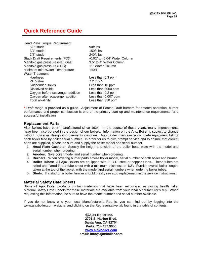
Quick Reference Guide Head Plate Torque Requirement 5/8" studs 90ft.lbs 3/4" studs 150ft.lbs 7/8" studs 240ft.lbs Stack Draft Requirements (FD)* -0.02” to -0.04” Water Column Manifold gas pressure (Nat. Gas) 3.5” to 4” Water Column Manifold gas pressure (LPG) 11” Water Column Minimum Inlet Water Temperature 140ºF Water Treatment Hardness Less than 0.3 ppm PH Value 7.2 to 9.5 Suspended solids Less than 10 ppm Dissolved solids Less than 3000 ppm Oxygen before scavenger addition Less than 0.2 ppm Oxygen after scavenger addition Less than 0.007 ppm Total alkalinity Less than 350 ppm * Draft range is provided as a guide. Adjustment of Forced Draft burners for smooth operation, burner performance and proper combustion is one of the primary start up and maintenance requirements for a successful installation Replacement Parts Ajax Boilers have been manufactured since 1924. In the course of these years, many improvements have been incorporated in the design of our boilers. Information on the Ajax Boiler is subject to change without notice as design improvements continue. Ajax Boiler maintains a complete equipment list for each boiler filed by boiler serial number. In order for us to give prompt service and to ensure that correct parts are supplied, please be sure and supply the boiler model and serial number.
1. Head Plate Gaskets: Specify the height and width of the boiler head plate with the model and serial number when ordering.
2. Anodes: Give boiler model and serial number when ordering. 3. Burners: When ordering burner parts advise boiler model, serial number of both boiler and burner. 4. Boiler Tubes: All Ajax Boilers are equipped with 2” O.D. steel or copper tubes. These tubes are
rolled and flared into a tube sheet with a minimum thickness of 1/2”. Furnish overall boiler length, taken at the top of the jacket, with the model and serial numbers when ordering boiler tubes.
5. Studs: If a stud on a boiler header should break, see stud replacement in the service instructions. Material Safety Data Sheets Some of Ajax Boiler products contain materials that have been recognized as posing health risks. Material Safety Data Sheets for these materials are available from your local Manufacturer’s rep. When requesting this information, be sure to have the model number and serial number available.
If you do not know who your local Manufacturer’s Rep is, you can find out by logging into the www.ajaxboiler.com website, and clicking on the Representative tab found in the table of contents.
Ajax Boiler Inc.
2701 S. Harbor Blvd. Santa Ana, CA 92704 Parts: 714.437.9050 www.ajaxboiler.com
email: [email protected]
AJAX BOILER INC. - ACE BOILER INC.
FACTORY LIMITED WARRANTY POLICYThe Ajax Boiler Factory limited warranty provides assurance that all products are free from manufacuteres defects at the time of shipment and meet specifi cations and performance described in the product literature.
It is important to understand the difference between a factory warranty and an installed warranty. There are many factors that can occur to the products after they are shipped that the company has no control over and can not fully verify. These includes:
1. Hidden damage during the shipping. 2. Handling damage. 3. Damage during storage. 4. Installation conditions. 5. Other unknown variables in the system design: maintenance, pulsation and vibrations.
The installed warranty is the responsibility of the architech, specifying engineer, contractor and/or owner who jointly have control over the application, installation, location, operating and maintenance conditions.
The Ajax Boiler Inc. warranty excludes extended liabilities. Extended liability typically occurs when products are installed without proper drainage, fl ooding containment or when safety devices are not tested and repaired or replaced when needed.
Product problems are often caused by the condition of the water, the lack of water treatment and/or the improper treatment of the water, insuffi cient combustion air, improper draft conditions, bolts not re-tightened, pipes not fl ushed and cleaned of oil, metal chips, rags, vibration and pulsation etc. These are installation, operating and/or maintenance conditions that are beyond the seller’s responsibility and are not covered by the factory warranty, but may be covered by the installer’s warranty.
The factory warranty covering company products is based upon extensive product development and testing. Combustion products under go certifi cation testing and approvals to Underwriters Laboratory (UL) standards. Auditing of the production of combustion products is conducted by a nationally recognized testing laboratory.
Pressure vessel products are designed and manufactured to American Society of Mechanical Engineering (ASME) and National Board (NB) Design standards. Design reviews, factory product manufacturing quality inspections and testing are carried out by a third party National Board authorized inspection agency.
Ajax Boiler Inc. products have proven themselves in service for over 85 years which indicates that the company products perform exceedingly well when normal installation, operating and maintenance conditions exist.
The following is a review from the terms and conditions of sale. Also included in paragraph two, below, is the Ajax Boiler Inc. non-conformance policy.
1. Ajax Boiler Inc. warrants its products against defective material and/or workmanship only. The warranty does not apply to operational failures, electrical failures, gasket leaks, and/or other malfunctions caused by improper application, installation and/or maintenance.
2. It is the buyer’s responsibility to inspect and accept the product, when received, as conforming to their purchase order, specifi cations and approved drawings. All claims for non-conformance, errors, shortages, etc. must be made within 10 days after receipt of the shipment. 3. Ajax Boiler Inc. do not provide a warranty or guarantee, express or implied, in any manner, form, usage of trade, merchant -ability or fi tness which extend beyond the product description and quotation. 4. Ajax Boiler Inc. liability is limited to the factory repair or replacement of warranty failures, or non-conformance, upon the return of the product to the factory.
5. Ajax Boiler Inc. is not liable for any direct or consequential damages.
6. The Ajax Boiler Inc. warranty is based upon section 23161(2) of the uniform commercial code and is printed in the terms and conditions of sale which is referenced in every quotation, on the back of sales order acknowledgements and invoices. It is legally correct and is an industry standard policy.
February-2007
AJAX BOILER INC. - ACE BOILER INC.
WARRANTYLIMITED
THERMAL SHOCK In addition to our standard one (1) year warranty against defective parts and workmanship, Ajax Boiler Inc. provides the following guarantee with all commercial hot water, forced circulation, space heating boilers:
Ajax Boiler Inc. guarantees this new boiler pressure vessel for twenty (20) years after date of installation from damage due tothermal shock. Thermal shock occurs when cold makeup water, up to 150ºF less than the boiler water outlet temperature, is added directly into the boiler while the boiler is operating within the normal temperature range from 140ºF to 250ºF with a temperature rise from 20ºF to 40ºF. This guarantee shall cover damage to the boiler tubes, tube headers, and tube sheets when such damage is attributed to unequal expansion, poor circulation and/or other causes quite often described as “thermal shock”. This guarantee does not cover damage or failures that can be attributed to corrosion, condensation, scale, boiler treatment chemicals, dirt accumulation, low water conditions, or any other abnormal operating conditions.
The liability of Ajax Boiler Inc. is limited solely to the replacement of the complete pressure vessel, with tubes, if found by our inspection to be damaged by thermal shock. In no event shall Ajax Boiler Inc. be held liable for replacement labor charges or for freight or handling charges.
2701 South Harbor Blvd.Santa Ana, California 92704United StatesTel. (714) 437-9050Fax (714) 437-9060http://[email protected]
June-2010
AJAX BOILER INC. - ACE BOILER INC.
LIMITED
WARRANTYAjax Boiler Inc. provides a limited warranty on its products against defective material and/or workmanship only. This limited warranty is not applicable to operational failures, electrical failures, gasket leaks, wear or malfunctions caused by improper application, installation, and/or maintenance.
Product Period - The following Limited Warranty period are from date of shipment: Boiler Pressure Vessels: One year. Carbon Steel Tank and Heat Exchanger Pressure Vessels: One year. Stainless Steel Tanks: Three years. Boiler Copper Fin Coils: Three years. Single-wall or Double-wall Tank/Exchanger Coils: One year. Single-wall or Double-wall Mini-Packs™: One year. Atlas Series Condensing Boiler: One year. Linings: (Pro-rated Warranty) In Section VIII Tanks: Glass 30" dia. and above (Five years). Glass 24" dia. and under (One year). Cement (Five years). Pre-Krete (Ten years). In Section IV Tanks: Glass (One year). Controls: Components manufactured by other than Ajax Boiler Inc. such as controls, instruments, forced draft burner, etc., provided with the boilers and packaged products are not covered by the Ajax Boiler Inc. Warranty. However, Ajax Boiler Inc. extends to the customer the same warranty provided by the manufacturer to Ajax Boiler Inc. The customer shall receive the full benefi ts of adjustments made to Ajax Boiler Inc. by the manufacturer.
Any claim for adjustment under this limited warranty must be made within the warranty period. Ajax Boiler Inc.’s liability shall be limited to factory repair or, at Ajax Boiler Inc.’s option, replacement of all parts which, upon test and examination by Ajax Boiler Inc., prove to be defective material and/or workmanship and within the above limited warranty. If required by Ajax Boiler Inc., parts which are claimed to be defective must be promptly delivered to the Ajax Boiler Inc. facility, transportation charges prepaid. This warranty does not cover the cost of labor, removal, or installation of the warranted item during the limited period.
This warranty is limited to the above and applies only for the period set forth. Ajax Boiler Inc. will not be liable for any loss damage, direct, incidental or consequential damages of any kind, whether based upon warranty, contract, negligence or strict liability and arising in connection with the sale, use or repair of the products. Ajax Boiler Inc.’s maximum liability shall exceed the contract price for the product’s merchantability or fitness for any particular purpose and in no event shall be held responsible for any consequential damages.
For complete Limited Warranty conditions see Section G and H under terms and condition of sale.
Ajax Boiler Inc., also doing business as Ace Boiler Inc., is referred to herein as Ajax Boiler Inc.
2701 South Harbor Blvd.Santa Ana, California 92704United StatesTel. (714) 437-9050Fax (714) 437-9060http://[email protected]
February-2007
AJAX BOILER INC. - ACE BOILER INC.
WARNINGPRODUCT
SAFETY NOTICEAJAX BOILER AND WATER HEATER PRODUCTS OPERATE AT HIGH TEMPERATURE AND PRESSURES
AND NOT FOR INSTALLATION ON COMBUSTIBLE FLOORING.
• Before using this product, read and understand instructions. Save these instructions for future use.• Before servicing, to prevent serious burns or injury, the boiler and water heater products must be cooled to less than 80°F (27°C) and the pressure must be 0 psi (0 bar).• Turn off the electrical power before making electrical connections to prevent electrical shock.• These products must be placed in a controlled location where untrained or unqualifi ed personnel cannot access the operating or safety controls, must not be able to come in contact with high temperature or high pressure parts and must not perform maintenance or demolition work. • All work performed must be by qualifi ed properly equipped personnel trained in the proper application, installation, and maintenance or demolition of plumbing, steam, and electrical equipment and/or systems in accordance with all applicable codes and ordinances.• Ajax Boilers and Water Heaters are complete package units with safety and operating controls and are constructed with non ASBESTOS materials. Any replacement gaskets, refractory, insulation, etc used must not contain Asbestos. • No additional insulation is required on the Boilers and Water Heaters. • Additions or replacement of insulation on any connecting pipes or accessories to the Boilers and/or Water Heaters must be of “NON-ASBESTOS” and contain only non-hazardous materials.• Crystalline Silica, a material known to cause cancer, may be encapsulated in some refractory or insulation materials and must be handled only by authorized trained personnel. Crystalline Silica as used is encapsulated and is not harm full in this form. Care must be taken during removal or replacement of refractory or insulation to remove it in bulk form and avoid generation or inhalation of dust. Removal must be properly performed by trained, qualifi ed and equipped personnel. This is also true of Asbestos not contained in Ajax products but may be otherwise contained in replacement materials or parts, in connecting piping or other nearby products. • All safety and operating controls must be set within the specifi ed operating limits and tested periodically to assure proper operation. All limit and operating controls must be installed in series on the boiler.• Connect drain pipes to a safe drain to prevent serious personal injury from relief valve discharge and or from boiler blow down discharge.• After installation, check for proper operation of all limit and operating controls before leaving the site.• Perform scheduled and annual inspections including checking Controls for proper calibration and performance.
Failure to follow these warnings, to allow access by unauthorized persons and the use of non-properly trained and equipped personnel in the operation, service, modifi cation, removal or demolition of these products or replacement of parts with non-authorized factory non-asbestos materials could cause damage, personal injury or death.
2701 South Harbor Blvd.Santa Ana, California 92704United StatesTel. (714) 437-9050Fax (714) 437-9060http://[email protected]
Effective: November-2008
DIM
EN
SIO
NS
- W
EIG
HT
S
MA
TE
RIA
LSS
erie
s 17
4A•
Bro
nze
bod
y co
nstr
uctio
n•
Non
met
allic
dis
c-to
-met
al s
eatin
gS
erie
s 74
0•
Iron
bod
y co
nstr
uctio
n•
Non
met
allic
dis
c-to
-met
al s
eatin
g
PR
ES
SU
RE
- T
EM
PE
RA
TU
RE
Ser
ies
174A
Pre
ssur
e ra
nge:
30
psi
to
150
psi
(2
to 1
0 b
ars)
with
corr
esp
ond
ing
high
BTU
/hr
ratin
gs f
rom
650
,000
to 1
4,37
0,00
0 B
TU/h
r.M
axim
um T
emp
erat
ure:
250
°F (1
21°C
).N
o. 3
74A
Pre
ssur
e ra
nge:
rat
ed u
p t
o 5
50,0
00 B
TU
/hr
at a
30
psi
(2 b
ars)
set
ting
only
.
Ser
ies
740
Pre
ssur
e ra
nge:
30
PS
I to
75 p
si (2
to
5 b
ars)
with
cor
-re
spo
ndin
g h
igh
ratin
gs
fro
m 9
25,0
00 t
o 1
0,70
0,00
0B
TU/h
r.M
axim
um T
emp
erat
ure:
250
°F (1
21°C
).
STA
ND
AR
DS
Test
ed a
nd r
ated
by
A.S
.M.E
. Nat
iona
l Boa
rd o
f B
oile
ran
d P
ress
ure
Ves
sel I
nsp
ecto
rs.
Mee
ts M
ilita
ry S
pec
. M
IL-V
-186
34B
, Ty
pe
I, C
lass
3A
,S
tyle
A (B
ronz
e B
ody)
, Sty
le B
(Iro
n B
ody)
.
CA
PAC
ITY
ES
-174
A-7
40 0
026
© W
atts
Reg
ulat
or
Co
., 19
98P
rinte
d in
U.S
.A.
USA:
815
Che
stnu
t St.,
No.
And
over
, MA
0184
5-60
98; w
ww.
wat
tsre
g.co
mCa
nada
: 543
5 No
rth S
ervi
ce R
d., B
urlin
gton
, ONT
. L7L
5H7
; ww
w.w
atts
cda.
com
HVNB
AS
ME
Size
(Dn)
Hei
ght
Leng
thW
eigh
tN
o.in
.m
mM
odel
in.
mm
in .
mm
lbs.
kg.
374A
3 ⁄4 x
3 ⁄420
x 2
0–
35 ⁄892
21 ⁄264
1.13
.517
4A3 ⁄4
x 3 ⁄4
20 x
20
M3
51 ⁄813
021 ⁄2
641.
50.7
174A
1 x
125
x 2
5M
153 ⁄4
146
376
3.13
1.4
174A
11 ⁄4 x
11 ⁄4
32 x
32
M1
83 ⁄821
343 ⁄4
121
6.25
2.8
174A
11 ⁄2 x
11 ⁄2
40 x
40
M9
229
47 ⁄812
47.
253.
317
4A2
x 2
50 x
50
M11
5 ⁄829
561 ⁄4
159
13.7
56.
2
Ser
ies
740
740
3 ⁄4 x
120
x 2
5M
155 ⁄8
143
376
1.88
.974
01
x 11 ⁄4
25 x
32
M71 ⁄4
184
31 ⁄289
3.13
1.4
740
11 ⁄4 x
11 ⁄2
32 x
40
M83 ⁄4
222
45 ⁄811
76.
132.
874
011 ⁄2
x 2
40 x
50
M91 ⁄4
235
51 ⁄413
37.
503.
474
02
x 21 ⁄2
50 x
65
M11
5 ⁄829
563 ⁄4
171
16.5
07.
5
Ser
ies
174A
BT
U/h
r S
team
Pre
ssu
re D
isch
arg
e C
apac
itie
sA
s te
sted
and
rate
d by
the
Nat
iona
l Boa
rd o
f Boi
ler a
nd P
ress
ure
Vess
el In
spec
tors
Set
3 ⁄4" x
3 ⁄4"
1" x
1"
11 ⁄4" x
11 ⁄4
"11 ⁄2
" x 1
1 ⁄2"
2" x
2"
Pres
sure
20 x
20m
m25
x 2
5mm
32 x
32m
m40
x 4
0mm
50 x
50m
mps
iba
rsM
odel
M3
Mod
el M
1M
odel
M1
Mod
el M
Mod
el M
302.
0765
0,00
01,
005,
000
1,68
2,00
02,
020,
000
3,81
5,00
033
2.27
695,
000
1,07
5,00
01,
788,
000
2,15
0,00
04,
080,
000
352.
4172
5,00
01,
125,
000
1,87
7,00
02,
250,
000
4,25
0,00
036
2.48
740,
000
1,14
5,00
01,
916,
000
2,31
0,00
04,
344,
000
402.
7680
0,00
01,
240,
000
2,07
1,00
02,
490,
000
4,69
0,00
045
3.10
875,
000
1,35
5,00
02,
265,
000
2,72
0,00
05,
130,
000
503.
4595
0,00
01,
470,
000
2,45
9,00
02,
950,
000
5,57
5,00
055
3.79
1,02
5,00
01,
590,
000
2,65
3,00
03,
190,
000
6,01
0,00
060
4.13
1,10
0,00
01,
702,
000
2,84
7,00
03,
425,
000
6,45
0,00
065
4.58
1,17
0,00
01,
820,
000
3,04
1,00
03,
660,
000
6,89
0,00
070
4.82
1,24
5,00
01,
935,
000
3,23
5,00
03,
890,
000
7,33
0,00
075
5.17
1,32
0,00
02,
055,
000
3,42
9,00
04,
125,
000
7,77
0,00
080
5.51
1,40
0,00
02,
166,
000
3,60
5,00
04,
360,
000
8,21
5,00
085
5.86
1,47
0,00
02,
285,
000
3,81
7,00
04,
590,
000
8,65
0,00
090
6.60
1,54
5,00
02,
400,
000
4,01
1,00
04,
825,
000
9,09
0,00
095
6.55
1,62
0,00
02,
520,
000
4,20
5,00
05,
060,
000
9,53
0,00
010
06.
891,
695,
000
2,63
5,00
04,
399,
000
5,29
0,00
09,
970,
000
105
7.23
1,77
0,00
02,
750,
000
4,59
3,00
05,
525,
000
10,4
10,0
0011
07.
581,
845,
000
2,86
5,00
04,
787,
000
5,76
0,00
010
,850
,000
115
7.92
1,92
0,00
02,
980,
000
4,98
1,00
05,
990,
000
11,2
90,0
0012
08.
271,
995,
000
3,10
0,00
05,
175,
000
6,22
5,00
011
,730
,000
125
8.61
2,07
0,00
03,
215,
000
5,37
0,00
06,
460,
000
12,1
70,0
0013
08.
962,
145,
000
3,33
0,00
05,
564,
000
6,69
0,00
012
,610
,000
135
9.30
2,22
0,00
03,
445,
000
5,75
8,00
06,
925,
000
13,0
50,0
0014
09.
652,
295,
000
3,56
5,00
05,
952,
000
7,16
0,00
013
,490
,000
145
9.99
2,37
0,00
03,
680,
000
6,14
6,00
07,
390,
000
13,9
30,0
0015
010
.34
2,44
5,00
03,
795,
000
6,34
0,00
07,
630,
000
14,3
70,0
00
Ser
ies
174A
Set
3 ⁄4" x
1"
1" x
11 ⁄4
"11 ⁄4
" x 1
1 ⁄2"
11 ⁄2" x
2"
2" x
21 ⁄2
"Pr
essu
re20
x 2
5mm
25 x
32m
m32
x 4
0mm
40 x
50m
m50
x 6
5mm
psi
bars
Mod
el M
3M
odel
M1
Mod
el M
1M
odel
MM
odel
M30
2.07
925,
000
1,30
0,00
02,
105,
000
2,90
0,00
05,
250,
000
332.
2798
9,00
01,
390,
000
2,25
0,00
03,
100,
000
5,61
3,00
035
2.41
1,03
2,00
01,
450,
000
2,34
5,00
03,
235,
000
5,85
5,00
036
2.48
1,05
3,00
01,
480,
000
2,39
5,00
03,
300,
000
5,97
5,00
040
2.76
1,13
9,00
01,
600,
000
2,59
0,00
03,
569,
000
6,46
1,00
045
3.10
1,24
5,00
01,
750,
000
2,83
0,00
03,
903,
000
7,06
7,00
050
3.45
1,35
2,00
01,
899,
000
3,07
5,00
04,
237,
000
7,67
2,00
055
3.79
1,45
9,00
02,
049,
000
3,31
5,00
04,
572,
000
8,27
7,00
060
4.13
1,56
6,00
02,
200,
000
3,56
0,00
04,
907,
000
8,88
3,00
065
4.58
1,67
2,00
02,
349,
000
3,80
0,00
05,
241,
000
9,48
8,00
070
4.82
1,77
9,00
02,
499,
000
4,04
5,00
05,
575,
000
10,0
93,0
0075
5.17
1,88
6,00
02,
649,
000
4,28
5,00
05,
909,
000
10,7
00,0
00
Ser
ies
740
Ser
ies
174A
-740
ASM
E W
ater
Pre
ssur
eRe
lief V
alve
sfo
r P
ress
ure
Pro
tect
ion
of
Ho
t W
ater
Hea
ting
Bo
ilers
Siz
es: 3 ⁄4
" th
roug
h 2"
(20
- 50
mm
)S
erie
s 17
4AB
ronz
e b
od
y sa
fety
rel
ief
valv
es f
or
pre
ssur
e p
rote
ctio
n o
nly
of
all t
ypes
of
hot
wat
er h
eatin
g b
oile
r eq
uip
men
t.
Pre
ssur
era
nge
30 t
o 1
50 p
si (2
- 1
0 b
ars)
with
co
rres
po
ndin
g h
igh
rat-
ing
s fr
om
650
,000
to
14,
370,
000
BT
U/h
r. F
emal
e in
let
and
outle
t co
nnec
tions
. S
izes
3 ⁄4"
to 2
" (2
0 to
50m
m).
Ser
ies
374A
Iro
n b
od
y w
ith f
org
ed b
ronz
e in
let,
550
,000
BT
U/h
r ra
ting
.S
ize
3 ⁄4"
(20m
m) o
nly.
Ser
ies
740
Iron
bod
y w
ith e
xpan
ded
out
lets
for
hot
wat
er s
pac
e he
atin
gb
oile
rs.
Pre
ssur
e ra
nge
30 t
o 75
psi
(2
to 5
bar
s) w
ith c
orre
-sp
ondi
ng h
igh
ratin
gs fr
om 9
25,0
00 to
10,
700,
000
BTU
/hr.
FEA
TU
RE
S•
Sea
t lo
cate
d a
bov
e d
rain
; wat
er c
an’t
be
trap
ped
and
sed
imen
t ca
n’t
foul
sea
t.•
Non
-mec
hani
cal s
eat-
to-d
isc
alig
nmen
t w
ill n
otst
ick
or f
reez
e.•
Wat
er s
eal o
f hi
gh t
emp
erat
ure
resi
stin
g m
ater
ial i
sola
tes
sprin
g w
orki
ng p
arts
fro
m w
ater
dur
ing
relie
f.
SP
EC
IFIC
AT
ION
SB
oile
r R
elie
f V
alve
sA
n A
SM
E S
ectio
n IV
cer
tifie
d p
ress
ure
relie
f va
lve
shal
l be
inst
alle
d o
n ea
ch b
oile
r as
no
ted
. T
he v
alve
sha
ll ha
ve a
BTU
rat
ing
in e
xces
s of
the
BTU
rat
ing
of t
he b
oile
rs h
eat-
ing
out
put
. E
ach
hot
wat
er s
pac
e he
atin
g b
oile
r sh
all
be
equi
pp
ed w
ith a
pre
ssur
e re
lief
valv
e se
t to
rel
ieve
bel
ow
the
max
imum
boi
ler
wor
king
pre
ssur
e. T
he v
alve
sha
ll fe
a-tu
re a
rai
sed
sea
t an
d n
on-
mec
hani
cal
dis
c al
ignm
ent.
Wo
rkin
g p
arts
and
sp
ring
sha
ll b
e is
ola
ted
fro
m a
ny d
is-
char
ge b
y a
high
tem
per
atur
e re
sist
ant
mat
eria
l. V
alve
sha
llb
e a
Wat
ts 1
74A
or
740
Ser
ies.
ES
-174
A-7
40
OP
ER
AT
ION
As
ther
mal
exp
ansi
on
cond
itio
ns d
evel
op
, p
ress
ure
bui
lds
upto
the
set
ting
of t
he r
elie
f va
lve.
Thi
s w
ill c
ause
dis
char
ging
of
smal
l qua
ntity
of w
ater
.S
houl
d o
per
atin
g c
ont
rols
fai
l, p
erm
ittin
g r
unaw
ay f
irin
g,
the
bo
iler
wat
er m
ay r
each
ste
am t
emp
erat
ures
. T
he v
alve
will
then
op
en t
o d
isch
arg
e st
eam
at
the
rate
or
fast
er t
han
the
bo
iler
can
gen
erat
e it,
thu
s re
sto
ring
sys
tem
pre
ssur
e to
asa
fer
leve
l.Im
po
rtan
t: T
he d
isch
arg
e lin
e m
ust
be
the
sam
e si
ze a
s th
eva
lve
out
let,
and
mus
t p
itch
do
wnw
ard
fro
m t
he v
alve
to
asa
fe p
lace
for
dis
pos
al.
Val
ve le
ver
mus
t b
e tr
ipp
ed a
t le
ast
onc
e a
year
to
insu
re t
hat
wat
erw
ays
are
clea
r.
Thi
s d
evic
e is
des
igne
d f
or
emer
gen
cysa
fety
rel
ief
and
sha
ll no
t b
e us
ed a
s an
op
erat
ing
cont
rol.
Seri
es 1
74A
Seri
es 7
40
For
Hot
Wat
er B
oile
r A
pp
licat
ion
s
Job
Nam
eC
ontr
acto
r
Job
Loc
atio
nA
pp
rova
l
Eng
inee
rC
ontr
acto
r’s
P.O
. No.
Ap
pro
val
Rep
rese
ntat
ive
Wat
ts p
rod
uct
spec
ifica
tio
ns i
n U
.S.
cust
om
ary
unit
s an
d m
etri
car
e ap
pro
xim
ate
and
are
pro
vid
ed f
or
refe
renc
e o
nly.
Wat
ts r
e-se
rves
the
rig
ht t
o c
hang
e o
r m
od
ify p
rod
uct
des
ign,
co
nstr
uctio
n,sp
ecifi
catio
ns,
or
mat
eria
ls w
itho
ut p
rio
r no
tice
and
with
out
incu
r-ri
ng a
ny o
blig
atio
n to
mak
e su
ch c
hang
es a
nd m
od
ifica
tio
ns o
nW
atts
pro
duc
ts p
revi
ous
ly o
r su
bse
que
ntly
so
ld.
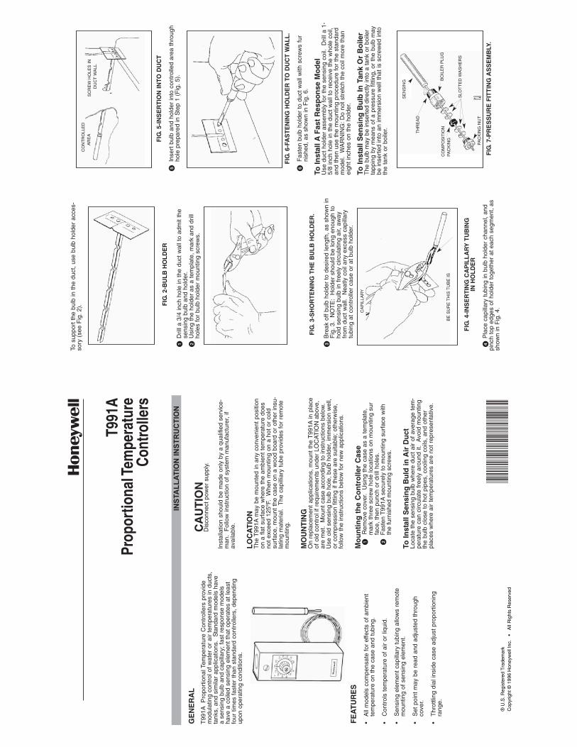
FIG
. 5-I
NS
ER
TIO
N IN
TO D
UC
T
�In
sert
bul
b an
d ho
lder
into
con
trol
led
area
thr
ough
ho
le p
repa
red
in S
tep
1 (F
ig.
5).
FIG
. 6-F
AS
TE
NIN
G H
OL
DE
R T
O D
UC
T W
AL
L.
�F
aste
n bu
lb h
olde
r to
duc
t w
all w
ith s
crew
s fu
rni
shed
, as
sho
wn
in F
ig.
6.
To In
stal
l AF
ast
Res
po
nse
Mo
del
Use
duc
t ho
lder
ass
embl
y fo
r th
e se
nsin
g co
il.
Dril
l a 1
-5/
8 in
ch h
ole
in t
he d
uct
wal
l to
rece
ive
the
who
le c
oil,
and
then
use
the
mou
ntin
g pr
oced
ure
for
the
stan
dard
mod
el.
WA
RN
ING
: D
o no
t st
retc
h th
e co
il m
ore
than
eigh
t in
ches
on
the
hold
er.
To In
stal
l Sen
sin
g B
ulb
In T
ank
Or
Bo
iler
The
bul
b m
ay b
e in
sert
ed d
irect
ly in
to a
tank
or
boile
rta
ppin
g by
mea
ns o
f a
pres
sure
fitt
ing,
or
the
bulb
may
be in
sert
ed in
to a
n im
mer
sion
wel
l tha
t is
scr
ewed
into
the
tank
or
boile
r.
FIG
. 7-P
RE
SS
UR
E F
ITT
ING
AS
SE
MB
LY.
To s
uppo
rt t
he b
ulb
in t
he d
uct,
use
bulb
hol
der
acce
s-so
ry (
see
Fig
. 2)
. FIG
. 2-B
UL
BH
OL
DE
R
�D
rill a
3/4
inch
hol
e in
the
duc
t w
all t
o ad
mit
the
sens
ing
bulb
and
hol
der.
�U
sing
the
hol
der
as a
tem
plat
e, m
ark
and
drill
ho
les
for
bulb
hol
der
mou
ntin
g sc
rew
s.
FIG
. 3-S
HO
RT
EN
ING
TH
E B
UL
B H
OL
DE
R.
�B
reak
off
bulb
hol
der
to d
esire
d le
ngth
, as
sho
wn
inF
ig.
3.
NO
TE
: H
olde
r sh
ould
be
long
eno
ugh
to
hold
sen
sing
bul
b in
fre
ely
circ
ulat
ing
air,
away
fr
om d
uct
wal
l. N
eatly
coi
l any
exc
ess
capi
llary
tu
bing
at
cont
rolle
r ca
se o
r at
bul
b ho
lder
.
FIG
. 4-I
NS
ER
TIN
G C
AP
ILL
AR
YT
UB
ING
IN
HO
LD
ER
�P
lace
cap
illar
y tu
bing
in b
ulb
hold
er c
hann
el,
and
pinc
h to
p ed
ges
of h
olde
r to
geth
er a
t ea
ch s
egm
ent,
assh
own
in F
ig.
4.CA
PIL
LAR
Y
TH
RE
AD
SE
NS
ING
CO
MP
OS
ITIO
NP
AC
KIN
G
PA
CK
ING
NU
T
SLO
TT
ED
WA
SH
ER
S
BO
ILE
R P
LUG
CO
NT
RO
LLE
DA
RE
AS
CR
EW
HO
LES
IN
DU
CT
WA
LL
BE
SU
RE
TH
IS T
UB
E I
S
T991
APr
opor
tiona
l Tem
pera
ture
Cont
rolle
rs
INS
TA
LL
AT
ION
IN
ST
RU
CT
ION
FE
AT
UR
ES
GE
NE
RA
L
T99
1AP
ropo
rtio
nal T
empe
ratu
re C
ontr
olle
rs p
rovi
dem
odul
atin
g co
ntro
l of
wat
er o
r ai
r te
mpe
ratu
res
in d
ucts
,ta
nks,
and
sim
ilar
appl
icat
ions
. S
tand
ard
mod
els
have
a se
nsin
g bu
lb a
nd c
apill
ary;
fas
t re
spon
se m
odel
sha
ve a
coi
led
sens
ing
elem
ent
that
ope
rate
s at
leas
tfo
ur t
imes
fas
ter
than
sta
ndar
d co
ntro
llers
, de
pend
ing
upon
ope
ratin
g co
nditi
ons.
• A
ll m
odel
s co
mpe
nsat
e fo
r ef
fect
s of
am
bien
tte
mpe
ratu
re o
n th
e ca
se a
nd t
ubin
g.
•
Con
trol
s te
mpe
ratu
re o
f ai
r or
liqu
id.
•
Sen
sing
ele
men
t ca
pilla
ry t
ubin
g al
low
s re
mot
e m
ount
ing
of s
ensi
ng e
lem
ent.
•
Set
poi
nt m
ay b
e re
ad a
nd a
djus
ted
thro
ugh
cove
r.
•
Thr
ottli
ng d
ial i
nsid
e ca
se a
djus
t pr
opor
tioni
ng
rang
e.
® U
.S. R
egis
tere
d T
rade
mar
kC
opyr
ight
© 1
996
Hon
eyw
ell I
nc.
•
All
Rig
hts
Res
erve
d
CA
UT
ION
Dis
conn
ect
pow
er s
uppl
y.
Inst
alla
tion
shou
ld b
e m
ade
only
by
a qu
alifi
ed s
ervi
ce-
man
. F
ollo
w in
stru
ctio
n of
sys
tem
man
ufac
ture
r, if
avai
labl
e.
LO
CA
TIO
N
The
T99
1Am
ay b
e m
ount
ed in
any
con
veni
ent
posi
tion
on a
fla
t su
rfac
e w
here
the
am
bien
t te
mpe
ratu
re d
oes
not
exce
ed 1
25ºF
. W
hen
mou
ntin
g on
a h
ot o
r co
ldsu
rfac
e, m
ount
the
cas
e on
a w
ood
boar
d or
oth
er in
su-
latin
g m
ater
ial.
The
cap
illia
ry t
ube
prov
ides
for
rem
ote
mou
ntin
g.
MO
UN
TIN
GO
n re
plac
emen
t ap
plic
atio
ns,
mou
nt t
he T
991A
in p
lace
of o
ld c
ontr
ol if
req
uire
men
ts u
nder
LO
CA
TIO
N a
bove
,ar
e m
et.
Mou
nt c
ase
acco
rdin
g to
inst
ruct
ions
bel
ow.
Use
old
sen
sing
bul
b ho
le,
bulb
hol
der,
imm
ersi
on w
ell,
or c
ompr
essi
on f
ittin
g if
thes
e ar
e su
itabl
e; o
ther
wis
e,fo
llow
the
inst
ruct
ions
bel
ow f
or n
ew a
pplic
atio
ns.
Mo
un
tin
g t
he
Co
ntr
olle
r C
ase
�R
emov
e co
ver.
Usi
ng t
he c
ase
as a
tem
plat
e,
mar
k th
ree
scre
w h
ole
loca
tions
on
mou
ntin
g su
rfa
ce,
then
pun
ch o
r dr
ill h
oles
.�
Fas
ten
T99
1Ase
cure
ly t
o m
ount
ing
surf
ace
with
th
e fu
rnis
hed
mou
ntin
g sc
rew
s.
To In
stal
l Sen
sin
g B
uld
in A
ir D
uct
Lo
cate
the
sen
sing
bul
b w
here
duc
t ai
r of
ave
rage
tem
-pe
ratu
re c
an c
ircul
ate
free
ly a
roun
d it.
Avo
id m
ount
ing
the
bulb
clo
se t
o ho
t pi
pes,
coo
ling
coils
, an
d ot
her
plac
es w
here
air
tem
pera
ture
s ar
e no
t re
pres
enta
tive.
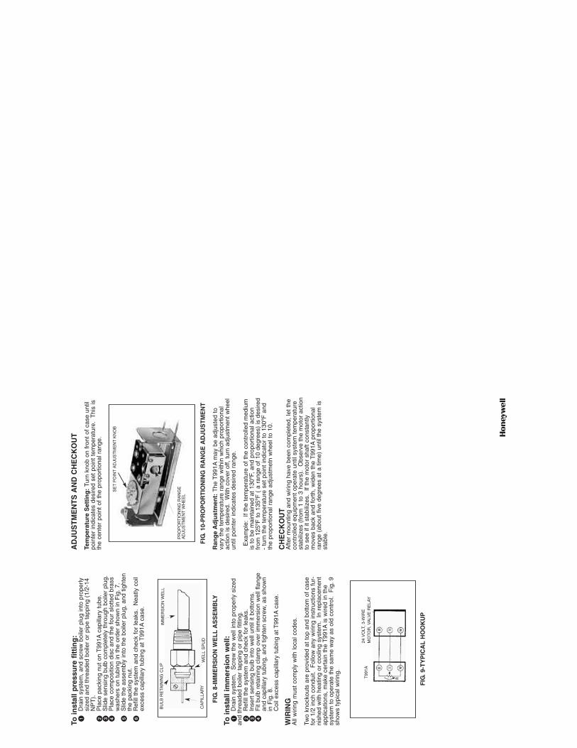
AD
JUS
TM
EN
TS
AN
D C
HE
CK
OU
T
Tem
per
atu
re S
etti
ng
: Tu
rn k
nob
on f
ront
of
case
unt
ilpo
inte
r in
dica
tes
desi
red
set
poin
t te
mpe
ratu
re.
Thi
s is
the
cent
er p
oint
of
the
prop
ortio
nal r
ange
.
FIG
. 10-
PR
OP
OR
TIO
NIN
G R
AN
GE
AD
JUS
TM
EN
T
Ran
ge
Ad
just
men
t: T
he T
991A
may
be
adju
sted
to
vary
the
tem
pera
ture
ran
ge w
ithin
whi
ch p
ropo
rtio
nal
actio
n is
des
ired.
W
ith c
over
off,
tur
n ad
just
men
t w
heel
until
poi
nter
indi
cate
s de
sire
d ra
nge.
Exa
mpl
e:
If th
e te
mpe
ratu
re o
f th
e co
ntro
lled
med
ium
is t
o be
mai
ntai
ned
at 1
30ºF
, an
d pr
opor
tiona
l act
ion
from
125
ºF t
o 13
5ºF
( a
ran
ge o
f 10
deg
rees
) is
des
ired
- tu
rn t
he t
empe
ratu
re s
et p
oint
indi
cato
r to
130
ºF a
ndth
e pr
opor
tiona
l ran
ge a
djus
tmet
n w
heel
to
10.
CH
EC
KO
UT
Afte
r m
ount
ing
and
wiri
ng h
ave
been
com
plet
ed,
let
the
cont
rolle
d eq
uipm
ent
oper
ate
until
sys
tem
tem
pera
ture
stab
ilize
s (f
rom
1 t
o 3
hour
s).
Obs
erve
the
mot
or a
ctio
nto
see
if it
sta
biliz
es.
If
the
mot
or s
haft
cons
tant
lym
oves
bac
k an
d fo
rth,
wid
en t
he T
991A
prop
ortio
nal
rang
e (a
bout
fiv
e de
gree
s at
a t
ime)
unt
il th
e sy
stem
isst
able
.
To in
stal
l pre
ssu
re f
itti
ng
:�
Dra
in s
yste
m,
and
scre
w b
oile
r pl
ug in
to p
rope
rly
size
d an
d th
read
ed b
oile
r or
pip
e ta
ppin
g (1
/2-1
4 N
PT
).�
Pla
ce p
acki
ng n
ut o
n T
991A
capi
llary
tub
e.�
Slid
e se
nsin
g bu
lb c
ompl
etel
y th
roug
h bo
iler
plug
.�
Pla
ce c
ompo
sitio
n di
sc a
nd t
he f
our
slot
ted
bras
s w
ashe
rs o
n tu
bing
in t
he o
rder
sho
wn
in F
ig.
7.�
Slid
e th
e as
sem
bly
into
the
boi
ler
plug
, an
d tig
hten
the
pack
ing
nut.
�R
efill
the
sys
tem
and
che
ck f
or le
aks.
N
eatly
coi
l ex
cess
cap
illar
y tu
bing
at T
991A
case
.
FIG
. 8-I
MM
ER
SIO
N W
EL
LA
SS
EM
BLY
To in
stal
l im
mer
sio
n w
ell:
�D
rain
sys
tem
. S
crew
the
wel
l int
o pr
oper
ly s
ized
and
thre
aded
boi
ler
tapp
ing
or p
ipe
fittin
g.�
Ref
ill t
he s
yste
m a
nd c
heck
for
leak
s.�
Inse
rt s
ensi
ng b
ulb
into
wel
l unt
il it
botto
ms.
�F
it bu
lb r
etai
ning
cla
mp
over
imm
ersi
on w
ell f
lang
ean
d ca
pilla
ry t
ubin
g, a
nd t
ight
en s
crew
, as
sho
wn
in F
ig.
8.C
oil e
xces
s ca
pilla
ry t
ubin
g at
T99
1Aca
se.
WIR
ING
All
wiri
ng m
ust
com
ply
with
loca
l cod
es.
Two
knoc
kout
s ar
e pr
ovid
ed a
t to
p an
d bo
ttom
of
case
for
1/2
inch
con
duit.
F
ollo
w a
ny w
iring
inst
ruct
ions
fur
-ni
shed
with
hea
ting
or c
oolin
g sy
stem
. I
n re
plac
emen
tap
plic
atio
ns,
mak
e ce
rtai
n th
e T
991A
is w
ired
in t
hesy
stem
to
oper
ate
the
sam
e w
ay a
s ol
d co
ntro
l. F
ig.
9sh
ows
typi
cal w
iring
.
FIG
. 9-T
YP
ICA
LH
OO
KU
P
24 V
OLT
, 3-
WIR
EM
OT
OR
, V
ALV
E R
ELA
YT
991A
BU
LB R
ETA
ININ
G C
LIP
CA
PIL
LAR
YW
ELL
SP
UD
IMM
ER
SIO
N W
ELL
SE
TP
OIN
TA
DJU
ST
ME
NT
KN
OB
PR
OP
OR
TIO
NIN
G R
AN
GE
AD
JUS
TM
EN
TW
HE
EL
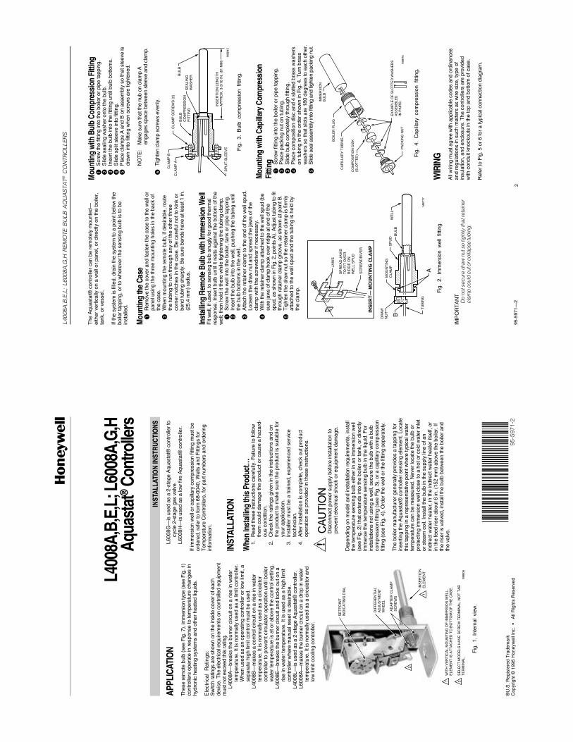
95-5
971—
22
L400
8A,B
,E,L
; L6
008A
,G,H
REM
OTE
BU
LB A
QU
AST
AT®
CO
NTR
OLL
ERS
The
Aqu
asta
t® c
ontr
olle
r ca
n be
rem
otel
y m
ount
ed—
eith
er v
ertic
ally
on
a w
all o
r pa
nel,
or d
irect
ly o
n th
e bo
iler,
tank
, or
vess
el.
If th
e sy
stem
is fi
lled,
dra
in th
e sy
stem
to a
poi
nt b
elow
the
boile
r ta
ppin
g, o
r to
whe
reve
r th
e se
nsin
g bu
lb is
to b
ein
stal
led.
Mou
ntin
g th
e Ca
se�
Rem
ove
the
cove
r an
d fa
sten
the
case
to th
e w
all o
rpa
nel u
sing
the
thre
e m
ount
ing
hole
s in
the
back
of
the
case
.�
Whe
n m
ount
ing
the
rem
ote
bulb
, if d
esira
ble,
rou
teth
e tu
bing
to r
un th
roug
h an
y of
the
othe
r th
ree
corn
er n
otch
es in
the
case
. Be
care
ful n
ot to
kin
k or
bend
tubi
ng s
harp
ly. B
e su
re b
ends
hav
e at
leas
t 1 in
.(2
5.4
mm
) rad
ius.
Inst
allin
g Re
mot
e Bu
lb w
ith Im
mer
sion
Wel
lF
it w
ell,
if us
ed, t
o se
nsin
g bu
lb s
nugl
y fo
r go
od th
erm
alre
spon
se. I
nser
t bul
b un
til it
res
ts a
gain
st th
e bo
ttom
of t
hew
ell;
then
hol
d it
ther
e w
hile
tigh
teni
ng th
e tu
bing
cla
mp.
�S
crew
the
wel
l int
o th
e bo
iler,
tank
or
pipe
tapp
ing.
�In
sert
the
bulb
into
the
wel
l, pu
shin
g th
e tu
bing
unt
ilth
e bu
lb b
otto
ms
in th
e w
ell.
�A
ttach
the
reta
iner
cla
mp
to th
e en
d of
the
wel
l spu
d.Lo
osen
the
draw
nut
and
spr
ead
the
jaw
s of
the
clam
p w
ith th
e sc
rew
driv
er if
nec
essa
ry.
�W
ith th
e re
tain
er c
lam
p at
tach
ed to
the
wel
l spu
d (b
esu
re ja
ws
of c
lam
p ho
ok o
ver r
idge
at e
nd o
f the
spud
, as
show
n in
Fig
. 2, p
oint
s A
). A
djus
t tub
ing
to fi
tth
roug
h re
tain
er c
lam
p gr
oove
, as
show
n at
poi
nt B
.�
Tig
hten
the
draw
nut
so
the
reta
iner
cla
mp
is fi
rmly
atta
ched
to th
e w
ell s
pud
and
the
tubi
ng is
hel
d by
the
clam
p.
Mou
ntin
g w
ith B
ulb
Com
pres
sion
Fitt
ing
�S
crew
the
fittin
g in
to th
e bo
iler
or p
ipe
tapp
ing.
�S
lide
seal
ing
was
her
onto
the
bulb
.�
Inse
rt th
e bu
lb in
to th
e fit
ting
until
bul
b bo
ttom
s.�
Slid
e sp
lit s
leev
e in
to fi
tting
.�
Pla
ce c
lam
ps A
and
B o
n as
sem
bly
so th
at s
leev
e is
draw
n in
to fi
tting
whe
n sc
rew
s ar
e tig
hten
ed.
NO
TE
:M
ake
sure
that
the
nub
on c
lam
p A
enga
ges
spac
e be
twee
n sl
eeve
and
cla
mp.
�T
ight
en c
lam
p sc
rew
s ev
enly
.
M87
77
WE
LLB
ULB
SP
UD
MO
UN
TIN
GC
LAM
P
A
DR
AW
N
UT
TU
BIN
G
B
INS
ER
T—
MO
UN
TIN
G C
LA
MP
SC
RE
WD
RIV
ER
SP
RE
AD
JA
WS
TO
FIT
OV
ER
RID
GE
ON
W
ELL
SP
UD
JAW
S
Fig
. 2.
Im
mer
sion
wel
l fit
ting.
IMP
OR
TA
NT
Do
not s
ecur
e dr
aw n
ut s
o tig
htly
that
reta
iner
clam
p co
uld
cut o
r col
laps
e tu
bing
.
M88
15
CLA
MP
B
CLA
MP
AC
LAM
P S
CR
EW
S (
2)
BU
LB
CO
MP
RE
SS
ION
F
ITT
ING
SE
ALI
NG
W
AS
HE
RBU
LB
INS
ER
TIO
N L
EN
GT
HA
PP
RO
X. 3
-3/1
6 IN
. (81
MM
)S
PLI
T S
LEE
VE Fig
. 3.
Bul
b co
mpr
essi
on f
ittin
g.
Mou
ntin
g w
ith C
apill
ary
Com
pres
sion
Fitti
ng�
Scr
ew fi
tting
into
the
boile
r or
pip
e ta
ppin
g.�
Pla
ce p
acki
ng n
ut o
n tu
bing
.�
Slid
e bu
lb c
ompl
etel
y th
roug
h fit
ting.
�P
lace
com
posi
tion
disc
and
4 s
lotte
d br
ass
was
hers
on tu
bing
in th
e or
der
show
n in
Fig
. 4. T
urn
bras
sw
ashe
rs s
o th
at s
lots
are
180
deg
rees
to e
ach
othe
r.�
Slid
e se
al a
ssem
bly
into
fitti
ng a
nd ti
ghte
n pa
ckin
g nu
t.
CO
MP
OS
ITIO
N D
ISK
(SLO
TT
ED
)
BO
ILE
R P
LUG
CA
PIL
LAR
Y T
UB
ING
EX
AM
PLE
OF
SLO
TT
ED
WA
SH
ER
S
AS
SE
MB
LED
IN
PA
IRS
:P
AC
KIN
G N
UT
M88
16
IMM
ER
SIO
NB
ULB
Fig
. 4.
Cap
illar
y co
mpr
essi
on f
ittin
g.
WIR
ING
All
wiri
ng m
ust a
gree
with
app
licab
le c
odes
and
ord
inan
ces
and
regu
latio
ns in
suc
h m
atte
rs a
s w
ire s
ize,
type
of
insu
latio
n, a
nd e
nclo
sure
. The
con
trol
lers
are
pro
vide
dw
ith c
ondu
it kn
ocko
uts
in th
e to
p an
d bo
ttom
of c
ase.
Ref
er to
Fig
. 5 o
r 6
for
a ty
pica
l con
nect
ion
diag
ram
.
X-X
X U
L
INST
ALLA
TIO
N IN
STRU
CTIO
NS
®U
.S. R
egis
tere
d T
rade
mar
kC
opyr
ight
© 1
995
Hon
eyw
ell I
nc.
• A
ll R
ight
s R
eser
vedL4
008A
,B,E
,L; L
6008
A,G,
HAq
uast
at® C
ontro
llers
APPL
ICAT
ION
The
se re
mot
e bu
lb (s
ee F
ig. 7
), im
mer
sion
type
(see
Fig
. 1)
cont
rolle
rs o
pera
te in
res
pons
e to
tem
pera
ture
cha
nges
inhy
dron
ic h
eatin
g sy
stem
s an
d ot
her
heat
ed li
quid
s.
Ele
ctric
al R
atin
gs:
Sw
itch
ratin
gs a
re s
how
n on
the
insi
de c
over
of e
ach
devi
ce. T
he e
lect
rical
requ
irem
ents
on
cont
rolle
d eq
uipm
ent
mus
t not
exc
eed
this
ratin
g.L4
008A
—br
eaks
the
burn
er c
ircui
t on
a ris
e in
wat
erte
mpe
ratu
re. I
t is
norm
ally
use
d as
a li
mit
cont
rolle
r.W
hen
used
as
an o
pera
ting
cont
rolle
r or
low
lim
it, a
sepa
rate
hig
h lim
it co
ntro
l mus
t be
used
.L4
008B
—m
akes
a c
ontr
ol c
ircui
t on
a ris
e in
wat
erte
mpe
ratu
re. I
t is
norm
ally
use
d as
a c
ircul
ator
cont
rolle
r to
pre
vent
circ
ulat
or o
pera
tion
until
boi
ler
wat
er te
mpe
ratu
re is
at o
r ab
ove
the
cont
rol s
ettin
g.L4
008E
—br
eaks
the
burn
er c
ircui
t and
lock
s ou
t on
aris
e in
wat
er te
mpe
ratu
re. I
t is
used
as
a hi
gh li
mit
cont
rolle
r w
here
man
ual r
eset
is d
esira
ble.
L400
8L—
is u
sed
as a
2-s
tage
Aqu
asta
t® c
ontr
olle
r.L6
008A
—m
akes
the
burn
er c
ircui
t on
a dr
op in
wat
erte
mpe
ratu
re. I
t is
norm
ally
use
d as
a c
ircul
ator
and
low
lim
it co
olin
g co
ntro
ller.
L600
8G—
is u
sed
as a
2-s
tage
Aqu
asta
t® c
ontr
olle
r to
cycl
e 2-
stag
e ga
s va
lve.
L600
8H—
is u
sed
as a
low
fire
Aqu
asta
t® c
ontr
olle
r.
If im
mer
sion
wel
l or
capi
llary
com
pres
sion
fitti
ng m
ust b
eor
dere
d, r
efer
to fo
rm 6
8-00
40, W
ells
and
Fitt
ings
for
Tem
pera
ture
Con
trol
lers
, for
par
t num
bers
and
ord
erin
gin
form
atio
n.
INST
ALLA
TIO
N
Whe
n In
stal
ling
this
Pro
duct
…1.
Rea
d th
ese
inst
ruct
ions
car
eful
ly. F
ailu
re to
follo
wth
em c
ould
dam
age
the
prod
uct o
r ca
use
a ha
zard
-ou
s co
nditi
on.
2.C
heck
the
ratin
gs g
iven
in th
e in
stru
ctio
ns a
nd o
nth
e pr
oduc
t to
mak
e su
re th
e pr
oduc
t is
suita
ble
for
your
app
licat
ion.
3.In
stal
ler
mus
t be
a tr
aine
d, e
xper
ienc
ed s
ervi
cete
chni
cian
.4.
Afte
r in
stal
latio
n is
com
plet
e, c
heck
out
pro
duct
oper
atio
n as
pro
vide
d in
thes
e in
stru
ctio
ns.
CA
UT
ION
Dis
conn
ect p
ower
sup
ply
befo
re in
stal
latio
n to
prev
ent e
lect
rical
sho
ck o
r eq
uipm
ent d
amag
e.
Dep
endi
ng o
n m
odel
and
inst
alla
tion
requ
irem
ents
, ins
tall
the
tem
pera
ture
sen
sing
bul
b ei
ther
in a
n im
mer
sion
wel
l(s
ee F
ig. 2
) th
at e
xten
ds in
to th
e bo
iler
or ta
nk, o
r di
rect
lyim
mer
se th
e te
mpe
ratu
re s
ensi
ng b
ulb
in th
e liq
uid.
For
inst
alla
tions
not
usi
ng a
wel
l, se
cure
the
bulb
with
a b
ulb
com
pres
sion
fitti
ng (s
ee F
ig. 3
), or
a c
apill
ary
com
pres
sion
fittin
g (s
ee F
ig. 4
). O
rder
the
wel
l or
the
fittin
g se
para
tely
.
The
boi
ler
man
ufac
ture
r ge
nera
lly p
rovi
des
a ta
ppin
g fo
rin
sert
ing
the
Aqu
asta
t® c
ontr
olle
r se
nsin
g el
emen
t. Lo
cate
this
tapp
ing
in a
rep
rese
ntat
ive
poin
t whe
re ty
pica
l wat
erte
mpe
ratu
re c
an b
e m
easu
red.
Nev
er lo
cate
the
bulb
or
prot
ectin
g im
mer
sion
wel
l clo
se to
a h
ot o
r co
ld w
ater
inle
tor
ste
am c
oil.
Inst
all t
he b
ulb
in th
e su
pply
line
of a
nin
dire
ct w
ater
hea
ter,
in th
e in
dire
ct w
ater
hea
ter
itsel
f, or
in th
e fe
ed r
iser
abo
ut 6
in. (
152
mm
) ab
ove
the
boile
r. If
the
riser
is v
alve
d, in
stal
l the
bul
b be
twee
n th
e bo
iler
and
the
valv
e.
95-5
971-
2
Fig
. 1.
Int
erna
l vi
ew.
M88
06
SE
TP
OIN
TIN
DIC
AT
ING
DIA
L
DIF
FE
RE
NT
IAL
AD
JUS
TM
EN
TW
HE
EL
AD
AP
TE
R C
LAM
PS
CR
EW
S
INS
ER
TIO
NE
LEM
EN
T
WIT
H V
ER
TIC
AL
MO
UN
TIN
G O
F IM
ME
RS
ION
WE
LL,
ELE
ME
NT
IS A
TT
AC
HE
D T
O B
OT
TO
M O
F T
HE
CA
SE
.
SE
LEC
T M
OD
ELS
HA
VE
SC
RE
W T
ER
MIN
AL,
NO
T T
AB
T
ER
MIN
AL.
1 2
2
1
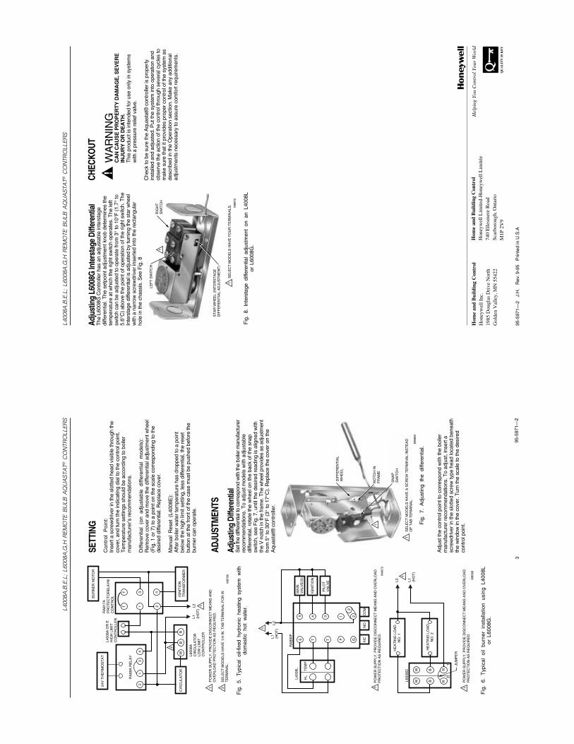
95-5
971—
24
L400
8A,B
,E,L
; L6
008A
,G,H
REM
OTE
BU
LB A
QU
AST
AT®
CO
NTR
OLL
ERS
Hom
e an
d B
uild
ing
Con
trol
Hon
eyw
ell L
imite
d-H
oney
wel
l Lim
itée
740
Elle
smer
e R
oad
Scar
boro
ugh,
Ont
ario
M1P
2V
9
Hel
ping
You
Con
trol
You
r W
orld
95-5
971—
2 J
.H.
Rev
. 9-9
5 P
rinte
d in
U.S
.A
QU
AL
ITY
IS
KE
Y
Hom
e an
d B
uild
ing
Con
trol
Hon
eyw
ell I
nc.
1985
Dou
glas
Dri
ve N
orth
Gol
den
Val
ley,
MN
554
22
Adju
stin
g L6
008G
Inte
rsta
ge D
iffer
entia
lT
he L
6008
G C
ontr
olle
r ha
s an
adj
usta
ble
inte
rsta
gedi
ffere
ntia
l. T
he s
etpo
int a
djus
tmen
t kno
b de
term
ines
the
tem
pera
ture
at w
hich
the
right
sw
itch
oper
ates
. The
left
switc
h ca
n be
adj
uste
d to
ope
rate
from
3°
to 1
0°F
(1.
7° to
5.6°
C)
abov
e th
e po
int o
f ope
ratio
n of
the
right
sw
itch.
The
Inte
rsta
ge d
iffer
entia
l is
adju
sted
by
turn
ing
the
star
whe
elw
ith a
nar
row
scr
ewdr
iver
inse
rted
into
the
rect
angu
lar
hole
in th
e ch
assi
s. S
ee F
ig. 8
CHEC
KOUT
WA
RN
ING
CA
N C
AU
SE
PR
OP
ER
TY
DA
MA
GE
, SE
VE
RE
INJU
RY
OR
DE
AT
H.
Thi
s pr
oduc
t is
inte
nded
for
use
only
in s
yste
ms
with
a p
ress
ure
relie
f val
ve.
Che
ck to
be
sure
the
Aqu
asta
t® c
ontr
olle
r is
pro
perly
inst
alle
d an
d ad
just
ed. P
ut th
e sy
stem
into
ope
ratio
n an
dob
serv
e th
e ac
tion
of th
e co
ntro
l thr
ough
sev
eral
cyc
les
tom
ake
sure
that
it p
rovi
des
prop
er c
ontr
ol o
f the
sys
tem
as
desc
ribed
in th
e O
pera
tion
sect
ion.
Mak
e an
y ad
ditio
nal
adju
stm
ents
nec
essa
ry to
ass
ure
com
fort
req
uire
men
ts.
M89
72
RIG
HT
SW
ITC
H
LEF
T S
WIT
CH
ST
AR
WH
EE
L (I
NT
ER
ST
AG
ED
IFF
ER
EN
TIA
L A
DJU
ST
ME
NT
)
1
1
SE
LEC
T M
OD
ELS
HA
VE
FO
UR
TE
RM
INA
LS.
Fig
. 8.
Int
erst
age
diffe
rent
ial
adju
stm
ent
on a
n L4
008L
or L
6008
G.
95-5
971—
23
L400
8A,B
,E,L
; L6
008A
,G,H
REM
OTE
BU
LB A
QU
AST
AT®
CO
NTR
OLL
ERS
L1
(HO
T)
L2 1
1 2
2
PO
WE
R S
UP
PLY
. PR
OV
IDE
DIS
CO
NN
EC
T M
EA
NS
AN
D
OV
ER
LOA
D P
RO
TE
CT
ION
AS
RE
QU
IRE
D.
SE
LEC
T M
OD
ELS
HA
VE
1/4
IN. T
AB
TE
RM
INA
L F
OR
WT
ER
MIN
AL.
L400
8A O
R E
HIG
H L
IMIT
C
ON
TR
OLL
ER
L600
8AC
IRC
ULA
TO
RLO
W L
IMIT
C
ON
TR
OLL
ERR
WB
CIR
CU
LAT
OR
IGN
ITIO
NT
RA
NS
FO
RM
ER
RA
89A
RE
LAY
RA
817A
PR
OT
EC
TO
RE
LAY
®C
ON
TR
OLB
UR
NE
R M
OT
OR
24V
TH
ER
MO
ST
AT
21
34
TT
1 2
3 4
M87
85
Fig
. 5.
Typ
ical
oil-
fired
hyd
roni
c he
atin
g sy
stem
with
dom
estic
hot
wat
er.
SETT
ING
Con
trol
Poi
nt:
Inse
rt a
scr
ewdr
iver
in th
e sl
otte
d he
ad v
isib
le th
roug
h th
eco
ver,
and
turn
the
indi
catin
g di
al to
the
cont
rol p
oint
.T
empe
ratu
re s
ettin
gs s
houl
d be
acc
ordi
ng to
boi
ler
man
ufac
ture
r’s r
ecom
men
datio
ns.
Diff
eren
tial
(on
adju
stab
le d
iffer
entia
l m
odel
s):
Rem
ove
cove
r an
d m
ove
the
diffe
rent
ial a
djus
tmen
t whe
el(F
ig. 1
or
7) to
a p
oint
on
the
scal
e co
rres
pond
ing
to th
ede
sire
d di
ffere
ntia
l. R
epla
ce c
over
.
Man
ual
Res
et (
L400
8E):
Afte
r bo
iler
wat
er te
mpe
ratu
re h
as d
ropp
ed to
a p
oint
belo
w th
e hi
gh li
mit
setti
ng, l
ess
diffe
rent
ial,
the
rese
tbu
tton
at th
e fr
ont o
f the
cas
e m
ust b
e pu
shed
bef
ore
the
burn
er c
an o
pera
te.
ADJU
STM
ENTS
Adju
stin
g Di
ffere
ntia
lS
et th
e di
ffere
ntia
l to
corr
espo
nd w
ith th
e bo
iler m
anuf
actu
rer
reco
mm
enda
tions
. To
adju
st m
odel
s w
ith a
djus
tabl
edi
ffere
ntia
l, ro
tate
the
whe
el o
n th
e ba
ck o
f the
sna
psw
itch,
see
Fig
. 7, u
ntil
the
desi
red
read
ing
is a
ligne
d w
ithth
e V
not
ch in
the
fram
e. T
he w
heel
pro
vide
s as
adj
ustm
ent
from
5°
to 3
0°F
(3°
to 1
7°C
). R
epla
ce th
e co
ver
on th
eA
quas
tat®
con
trol
ler.
L1
(HO
T)
L2
1
1P
OW
ER
SU
PP
LY. P
RO
VID
E D
ISC
ON
NE
CT
ME
AN
S A
ND
OV
ER
LOA
D
PR
OT
EC
TIO
N A
S R
EQ
UIR
ED
.
JUM
PE
R
M89
68
HE
AT
ING
LO
AD
NO
. 2
HE
AT
ING
LO
AD
NO
. 1
RR
BB
WW
21
L600
8G
Fig
. 6.
Typ
ical
oil
burn
er i
nsta
llatio
n us
ing
L400
8Lor
L60
08G
.
L1
(HO
T)
L2
1
1P
OW
ER
SU
PP
LY. P
RO
VID
E D
ISC
ON
NE
CT
ME
AN
S A
ND
OV
ER
LOA
D
PR
OT
EC
TIO
N A
S R
EQ
UIR
ED
.
L400
8L
HL
TE
MP
RA
890F
65
T
4T
3
F1 2
2G NC
NO
CO
M
PIL
OT
VA
LVE
IGN
ITIO
N
MA
INV
ALV
E(S
)
M46
72
M89
69
DIF
FE
RE
NT
IAL
WH
EE
L
NO
TC
H IN
FR
AM
E
SN
AP
SW
ITC
H
SE
LEC
T M
OD
ELS
HA
VE
A S
CR
EW
TE
RM
INA
L IN
ST
EA
D
OF
TA
B T
ER
MIN
AL.
1
1
Fig
. 7.
Adj
ustin
g th
e di
ffere
ntia
l.
Adj
ust t
he c
ontr
ol p
oint
to c
orre
spon
d w
ith th
e bo
iler
man
ufac
ture
r re
com
men
datio
ns. T
o ad
just
, ins
ert a
scre
wdr
iver
in th
e sl
otte
d sc
rew
type
hea
d lo
cate
d be
neat
hth
e w
indo
w in
the
cove
r. T
urn
the
scal
e to
the
desi
red
cont
rol p
oint
.
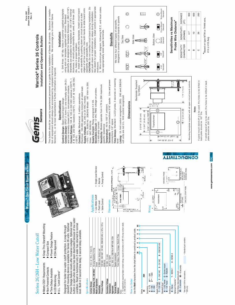
Sp
ecif
icat
ion
sC
on
tro
l D
esig
n:
Op
en
cir
cuit
bo
ard
de
sig
nC
on
tact
Des
ign
: S
PD
T (
1 f
orm
C):
on
e n
orm
ally
op
en
(N
.O.)
an
d o
ne
no
rma
lly c
lose
d (
N.C
.),
no
n-p
ow
ere
d c
on
tact
s.C
on
tact
Rat
ing
s:
10
A @
12
0 o
r 2
40
VA
C r
esi
stiv
e (
12
0°F
), 1
A @
12
0,
24
0 V
AC
re
sist
ive
(1
50
°F),
1/3
H.P
. @
12
0,
24
0 V
AC
(12
0°F
)C
on
tact
Lif
e:
Me
cha
nic
al:
5 m
illio
n o
pe
ratio
ns.
Ele
ctri
cal:
10
0,0
00
op
era
tion
s m
inim
um
at
rate
d l
oa
d.
Su
pp
ly V
olt
age:
12
0,
24
0 o
r 2
4 V
AC
mo
de
ls:
+1
0%
- 1
5%
, 5
0/6
0 H
z.
20
8/2
40
Mo
de
l: 1
87
Vm
in t
o 2
55
Vm
ax.
V
AC
50
/60
Hz
Su
pp
ly C
urr
ent:
Re
lay
en
erg
ize
d 4
.4 V
A.
Sec
on
dar
y C
ircu
it:
12
VA
C R
MS
vo
ltag
e o
n p
rob
es,
1.5
mill
i-a
mp
cu
rre
nt.
Sen
siti
vity
: M
od
els
op
era
te f
rom
4.7
K t
o 2
6K
ma
xim
um
spe
cific
re
sist
an
ceTe
mp
erat
ure
: -4
0 t
o 1
50
° F.
am
bie
nt.
Term
inal
s: P
rob
e c
on
ne
ctio
ns
3/1
6”
spa
de
: L
ine
an
d p
ow
er
con
ne
ctio
ns
1/4
” sp
ace
Tim
e D
elay
s: S
tan
da
rd -
LL
CO
pro
be
, 3
se
con
ds
on
low
eri
ng
leve
lL
isti
ng
: U
L li
mit
con
tro
l re
cog
niti
on
(3
53
).
24
0 a
nd
20
8/2
40
volt
un
its a
re n
ot
U.L
. lim
it co
ntr
ol r
eco
gn
ize
d.
Inst
alla
tio
n1
. D
rill
thre
e .
18
7 d
ia.
ho
les
in c
ust
om
er
sup
plie
d b
ack
pla
teu
sin
g s
tick
on
te
mp
late
su
pp
lied
with
co
ntr
ol.
Sta
nd
ard
sta
nd
off
s a
re d
esi
gn
ed
fo
r b
ack
pla
te t
hic
kne
ss o
f .0
62
(1
/16
”).
Sta
nd
off
s a
re a
vaila
ble
fo
r b
ack
pla
tes
of
.12
5 (
1/8
”) n
om
ina
lth
ickn
ess
. If
re
tro
fit p
late
sta
nd
off
s a
re u
sed
, d
rill
thre
e .
25
0d
ia.
ho
les
in p
rop
er
loca
tion
.2
. I
nst
all
thre
e s
tan
do
ffs
on
to b
ack
pla
te.
Inst
all
circ
uit
bo
ard
on
to s
tan
do
ffs
by
pu
shin
g d
ow
n o
n c
ircu
it b
oa
rd a
t o
ute
re
dg
es
of
all
fou
r co
rne
rs.
Use
bo
th h
an
ds
to s
lide
bo
ard
on
tost
an
do
ffs
un
til s
tan
do
ffs
lock
.C
AU
TIO
N:
Do
no
t o
verf
lex
circ
uit
bo
ard
du
rin
g in
sta
llatio
n.
Do
no
t p
ush
do
wn
on
tra
nsf
orm
er
or
rela
ys d
uri
ng
in
sta
llatio
n.
Se
e s
ketc
h f
or
pro
pe
r in
sta
llatio
n.
Inst
all
con
tro
l in
ap
pro
pri
ate
en
clo
sure
.3
. W
ire
co
ntr
ol
pe
r d
iag
ram
, fo
llow
ing
N.E
.C.
an
d l
oca
l co
de
s.U
se a
pp
rop
ria
tely
siz
ed
sp
ad
e t
erm
ina
ls.
Th
is b
ulle
tin s
ho
uld
be
use
d b
y e
xpe
rie
nce
d p
ers
on
ne
l as
a g
uid
e t
o t
he
inst
alla
tion
of
Se
rie
s 2
6 c
on
tro
ls.
Se
lect
ion
or
inst
alla
-tio
n o
f e
qu
ipm
en
t sh
ou
ld a
lwa
ys b
e a
cco
mp
an
ied
by
com
pe
ten
t te
chn
ica
l a
ssis
tan
ce.
We
en
cou
rag
e y
ou
to
co
nta
ct G
em
sS
en
sors
In
c.,
or
its l
oca
l re
pre
sen
tativ
e i
f fu
rth
er
info
rma
tion
is
req
uir
ed
.
No
tes
If p
an
el
mo
un
t st
an
d-o
ff i
s to
be
use
d,
thru
-ho
les
to b
e d
rille
d i
nb
ack
pla
te s
ho
uld
be
.1
87
” D
ia.
If r
etr
ofit
sta
nd
-off
is
to b
e u
sed
, th
ru-h
ole
s to
be
dri
lled
in
ba
ckp
late
sh
ou
ld b
e .
25
0”
Dia
.
Dim
ensi
on
s
Ba
ckp
late
Su
pp
lied
by
Oth
ers
Tra
nsf
orm
er
3/1
6”
(.4
8 c
m)
RE
F
�
�
�
�
1-3
/4”
(4.4
5 c
m)
�
�
�
�2-3
/16
” (5
.55
cm
)�
�
1-5/8” (4.13 cm)
2-1/2” (6.35 cm)
1”
(2.5
4 c
m)
�
�
1-1/16”(2.70 cm) REF
�
�
Mo
un
ting
te
mp
late
su
pp
lied
with
all
op
en
cir
cuit
bo
ard
co
ntr
ols
.
1-7
/8”
(4.7
6 c
m)
�
�
1/2
”(1
.27
cm
)
�
�
*Bas
ed o
n ty
pe M
TW
or
TH
HN
wire
,
#14
or
#16
Aw
g
Sen
siti
viti
es v
s M
axim
um
Pro
be
Wir
e D
ista
nce
*
SE
NS
ITIV
ITY
CH
AR
AC
TE
RS
EN
SIT
IVIT
Y(K
OH
MS
)D
ISTA
NC
E(F
T)
A4
.79
00
B1
06
00
C2
62
50
We
ha
ve f
ou
r d
iffe
ren
t ty
pe
s o
f st
an
do
ffs,
de
sig
ne
d t
o c
on
ne
ct c
iru
cit
bo
ard
s to
pa
ne
ls
Top
Vie
w
Sid
e V
iew
Bo
tto
m V
iew
1/1
6”
Sta
nd
off
1/8
”S
tan
do
ffR
etr
ofit
Sta
nd
off
Cir
cuit
Bo
ard
Sta
nd
off
Scr
ew
Mo
un
tS
tan
do
ff
1/1
6”
1/8
”Sta
nd
off
s
War
rick
® S
erie
s 26
Co
ntr
ols
Inst
alla
tio
n a
nd
Op
erat
ion
Bu
llet
in
Fo
rm 2
60S
hee
t P
/N 1
0020
3-1
Rev
. H
ww
w.g
emss
enso
rs.c
om
E-4
*See
pag
e E-
29 fo
r des
crip
tions
.**
26H
only
– St
anda
rd p
art n
umbe
rs
XX
XX
X26
XX
Serie
s26
Sens
itivi
tyA
– 4.
7KB
– 10
KC
– 26
KSu
pply
Vol
tage
1 –
120
VAC
Stan
doff
Styl
e*A
– 1/
16˝ P
anel
B –
1/8˝
Pan
elEn
clos
ure
0 –
None
Optio
nal C
hara
cter
*Ti
me
Dela
y (d
ecre
asin
g le
vel)
03 –
3 s
econ
ds
26H
2 –
240
VAC
3 –
24 V
AC8
– 20
8/24
0 VA
C
C –
Scre
w m
ount
D –
Retro
fit
1 –
NEM
A 1
06 –
6 s
econ
ds
4 –
NEM
A 4
D**
– 50
KE*
* –
100K
A.C.
SUP
PLY
TRAN
SFOR
MER
REFE
RENC
E PR
OBE
TANK
, IF
MET
ALLI
C,M
AY B
E US
EDIN
PLA
CE O
FRE
FERE
NCE
PROB
E.
L1L2
G NC C NO
LLCO RE
SET
RESE
T BU
TTON
OPTI
ONAL
LOW
LEV
EL C
UTOF
F PR
OBE
WAR
RICK
® O
PEN C
IRCU
IT B
OARD
CON
TROL
S
Seri
es 2
6/26
H –
Low
Wat
er C
utof
f�
Mee
ts C
SD1
Requ
irem
ents
�
Snap
-Thr
u St
ando
ff M
ount
ing
� No
n Po
wer
ed C
onta
cts
� Co
mpa
ct S
ize�
Tim
e De
lays
Ava
ilabl
e �
Pow
er O
utag
e Fe
atur
e�
LED
Mon
itorin
g �
CSA
Appr
oved
� U.
L. “
Lim
it Co
ntro
l”
Desi
gned
for b
oile
r low
-wat
er c
utof
f pro
tect
ion.
A s
nap-
thro
ugh
stan
doff
mou
ntin
g de
vice
is a
vaila
ble
for S
erie
s 26
uni
ts. O
ptio
nal
Pow
er O
utag
e fe
atur
e re
sets
afte
r nui
sanc
e ou
tage
s. O
ptio
nal r
eset
bu
tton
is u
sed
whe
n de
vice
has
bee
n de
activ
ated
bec
ause
of l
ow w
ater
co
nditi
on. R
eset
is fu
nctio
nal o
nly
if w
ater
has
retu
rned
to n
orm
al
leve
l. Bu
ilt-in
3 s
econ
d tim
e de
lay,
6 s
econ
d de
lay
avai
labl
e.
Spec
ifi ca
tions
Cont
act D
esig
n 1
N.O.
& 1
N.C
. (1
form
C)
Cont
act R
atin
g (1
20, 2
40 V
AC)1
10 a
mp
Resi
stiv
e 1/
3 hp
Mod
e of
Ope
ratio
n Di
rect
Sens
itivi
ty
0-26
K oh
m, f
acto
ry s
etPr
imar
y Vo
ltage
12
0 VA
C, 2
40 V
AC2 ,
24 V
AC, 2
08/2
40 V
AC (+
10%
/-15%
)
50
/60
HzSe
cond
ary
Volta
ge
12 V
AC, 1
.5 m
ATe
mpe
ratu
re
-40°
F to
150
°FAp
prov
als
U.L.
353
, U.L
. 508
File
# M
P143
0, C
SATe
rmin
al S
tyle
Sp
ade
conn
ectio
nOp
tions
Ti
me
Dela
ys, P
ower
Out
age,
Ret
rofi t
Pla
te
App
licat
ions
• Lo
w-W
ater
Cut
off
• Si
ngle
-Lev
el S
ervi
ce•
Poin
t Lev
el
• Al
arm
s•
Valv
e Co
ntro
l •
Pum
p Co
ntro
l
Note
s:1.
For
app
licat
ions
requ
iring
hig
her c
onta
ct ra
tings
, req
uest
info
rmat
ion
on 2
6P (1
6 am
p co
ntac
t rat
ed).
2. 2
40 v
olt i
s no
t U.L
.
How
to O
rder
Use
the
Bold
cha
ract
ers
from
the
char
t bel
ow to
con
stru
ct a
pro
duct
cod
e.
Wir
ing
Dim
ensi
ons
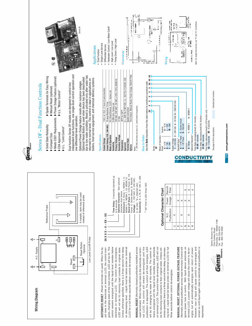
ww
w.g
emss
enso
rs.c
om
E-5
*See
pag
e E-
29 fo
r des
crip
tions
.–
Stan
dard
par
t num
bers
XX
XX
XDF
XXXX
XX
Serie
sDF
Mod
e of
Ope
ratio
nDi
rect A –
4.7K
B –
10K
C –
26K
Supp
ly V
olta
ge1
– 12
0 VA
CSt
ando
ff St
yle*
A –
1/16
˝ Pan
elB
– 1/
8˝ P
anel
Encl
osur
e0
– No
neOp
tiona
l Cha
ract
er*
Tim
e De
lay
(incr
easi
ng le
vel)
H/L
func
tion
01-2
0 –
seco
nds
Tim
e De
lay
(dec
reas
ing
leve
l) H/
L fu
nctio
n01
-20
– se
cond
sTi
me
Dela
y (d
ecre
asin
g le
vel)
LLCO
func
tion
only
03 –
3 s
econ
ds
Inve
rse
K –
4.7K
L –
10K
M –
26K
2 –
240
VAC
3 –
24 V
AC8
– 20
8/24
0 VA
C
C –
Scre
w m
ount
D –
Retro
fit
1 –
NEM
A 1
06 –
6 s
econ
ds
4 –
NEM
A 4
U L¤
Seri
es D
F –
Dua
l Fun
ctio
n Co
ntro
ls�
Solid
Sta
te R
elia
bilit
y �
Spad
e Te
rmin
als
for E
asy
Wiri
ng�
Com
pact
Size
�
Man
ual R
eset
(opt
iona
l)�
Mee
ts C
SD1
Requ
irem
ents
�
Pow
er O
utag
e Fe
atur
e (o
ptio
nal)
� CS
A Ap
prov
ed
� U.
L. “
Mot
or C
ontro
l”�
U.L.
“Li
mit
Cont
rol”
Dual
func
tion
Serie
s DF
mod
els
are
desi
gned
to c
ontro
l tw
o in
depe
nden
t lev
el fu
nctio
ns, o
ne s
ingl
e-le
vel c
ontro
l ope
ratio
n an
d on
e di
ffere
ntia
l-lev
el o
pera
tion.
Optio
nal P
ower
Out
age
feat
ure
rese
ts a
fter n
uisa
nce
outa
ges.
Op
tiona
l Res
et B
utto
n is
use
d w
hen
devi
ce h
as b
een
deac
tivat
ed
due
to lo
w w
ater
con
ditio
n. R
eset
is a
ctiv
ated
onl
y af
ter w
ater
has
re
turn
ed to
nor
mal
leve
l. Th
is c
ontro
l is
idea
l in
appl
icat
ions
on
boile
rs, f
ood
serv
ice
equi
pmen
t, an
d ch
emic
al d
eliv
ery
syst
ems.
Spec
ifi ca
tions
Cont
act D
esig
n 1
N.O.
& 1
N.C
. (1
form
C) e
xtra
func
tion
Cont
act R
atin
g (1
20, 2
40 V
AC)
10 a
mp
Resi
stiv
e 1/
3 hp
Mod
e of
Ope
ratio
n H/
L Di
rect
/Inve
rse,
LLC
O –
fact
ory
set
Sens
itivi
ty
0-26
K oh
m, f
acto
ry s
etPr
imar
y Vo
ltage
12
0 VA
C, 2
40 V
AC1 ,
24 V
AC (+
10%
/-15%
) 50/
60 H
zSe
cond
ary
Volta
ge
12 V
ACTe
mpe
ratu
re
-40°
F to
150
°FAp
prov
als
U.L.
508
File
# M
P143
0, U
.L. 3
53 F
ile #
E44
426,
CSA
Term
inal
Sty
le
Spad
e co
nnec
tion
Optio
ns
Tim
e De
lays
, Man
ual R
eset
, Pow
er O
utag
e, R
etro
fi t P
late
Note
s:1.
240
VAC
uni
t doe
s no
t car
ry U
.L. L
imit
Cont
rol r
ecog
nitio
n.
How
to O
rder
Use
the
Bold
cha
ract
ers
from
the
char
t bel
ow to
con
stru
ct a
pro
duct
cod
e.
App
licat
ions
• Du
al F
unct
ion
• Si
ngle
-Lev
el S
ervi
ce•
Diffe
rent
ial S
ervi
ce•
Feed
wat
er C
ontro
l / L
ow-W
ater
Cut
off
• Hi
gh L
evel
/ Lo
w L
evel
• Pu
mp
Dow
n / H
igh
Leve
l
Dim
ensi
ons
Wir
ing
Note
: For
sin
gle
leve
l ser
vice
, use
“H”
and
“G”
con
nect
ions
.
Serie
s DF
AU
TO
MA
TIC
RE
SE
T (
Re
set t
erm
ina
ls n
ot u
sed
) W
he
n th
e li
q-
uid
ris
es
to t
he
ele
ctro
de
on
te
rmin
al
LL
CO
, th
e c
on
tro
l e
ne
r-
giz
es,
ch
an
gin
g s
tate
of
the
loa
d c
on
tact
s. (
LE
D w
ill b
e li
t)
Th
eco
ntr
ol
rem
ain
s e
ne
rgiz
ed
un
til t
he
liq
uid
le
vel
rece
de
s b
elo
we
lect
rod
e o
n t
erm
ina
l L
LC
O.
Th
e c
on
tro
l th
en
de
-en
erg
ize
s,
(LE
D w
ill n
ot
be
lit)
re
turn
ing
lo
ad
co
nta
cts
to o
rig
ina
l st
ate
.U
nle
ss o
the
rwis
e s
pe
cifie
d,
the
re i
s a
th
ree
se
con
d t
ime
de
lay
on
de
cre
asi
ng
le
vel.
Liq
uid
mu
st b
e b
elo
w p
rob
e o
n t
erm
ina
lL
LC
O f
or
a f
ull
thre
e s
eco
nd
s b
efo
re c
on
tro
l d
e-e
ne
rgiz
es.
MA
NU
AL
RE
SE
T (
No
rma
lly c
lose
d p
ush
bu
tto
n in
sta
lled
acr
oss
rese
t te
rmin
als
) W
he
n th
e li
qu
id r
ise
s to
the
ele
ctro
de
on
term
i-
na
l L
LC
O,
the
co
ntr
ol
wil
l re
ma
in d
e-e
ne
rgiz
ed
un
til
the
pu
shb
utt
on
is
de
pre
sse
d.
Th
e c
on
tro
l w
ill t
he
n e
ne
rgiz
e,
(LE
Dw
ill b
e l
it) c
ha
ng
ing
th
e s
tate
of
the
co
nta
cts.
Th
e c
on
tro
l re
-
ma
ins
en
erg
ize
d u
ntil
th
e l
iqu
id l
eve
l re
ced
es
be
low
ele
ctro
de
on
te
rmin
al L
LC
O.
Th
e c
on
tro
l th
en
de
-en
erg
ize
s, (
LE
D w
ill n
ot
be
lit)
re
turn
ing
loa
d c
on
tact
s to
th
eir
ori
gin
al s
tate
. U
nle
ss o
th-
erw
ise
sp
eci
fied
, th
ere
is a
thre
e s
eco
nd
tim
e d
ela
y o
n d
ecr
ea
s-in
g le
vel.
Liq
uid
mu
st b
e b
elo
w p
rob
e o
n t
erm
ina
l LL
CO
fo
r fu
llth
ree
se
con
ds
be
fore
co
ntr
ol
de
-en
erg
ize
s.
MA
NU
AL
RE
SE
T O
PT
ION
AL
PO
WE
R O
UTA
GE
FE
AT
UR
E(N
orm
ally
clo
sed
pu
shb
utt
on
acr
oss
re
set t
erm
ina
ls)
Co
ntr
ol w
ill
ign
ore
po
we
r lo
ss t
o c
on
tro
l. W
ith l
iqu
id a
bo
ve e
lect
rod
e o
nte
rmin
al L
LC
O,
a p
ow
er
ou
tag
e w
ill c
au
se t
he
co
ntr
ol t
o d
e-e
n-
erg
ize
, b
ut
will
au
tom
atic
ally
en
erg
ize
up
on
re
turn
of
po
we
r.
Ho
we
ver,
lo
ss o
f liq
uid
will
ca
use
co
ntr
ol
to d
e-e
ne
rgiz
e a
nd
rem
ain
so
un
til li
qu
id a
ga
in r
ise
s to
ele
ctro
de
an
d p
ush
bu
tto
n is
de
pre
sse
d.
Wir
ing
Dia
gra
m
26
X X
X –
X –
XX
– X
X
Tim
e D
elay
: 3
se
con
ds
sta
nd
ard
up
to 6
se
con
ds
Op
tio
nal
Ch
arac
ter:
S
ee
op
tion
al
cha
ract
er
cha
rt b
elo
wE
ncl
osu
re:
0-
No
ne
, 1
- N
EM
A 1
, 4
-N
EM
A 4
, 7
- N
EM
A 7
, 1
2-
NE
MA
12
Sta
nd
off
Sty
le:
A-
1/1
6 P
an
el,
B-
1/8
Pa
ne
l, C
- S
cre
w M
ou
nt,
D-
Re
tro
fitV
olt
age:
1
- 1
20
VA
C,
2-
24
0 V
AC
,3
- 2
4 V
AC
, *8
= 2
08
/24
0 V
AC
Sen
siti
vity
: A
- 4
.7K
, B
- 1
0K
, C
- 2
6K
* 1
87
Vm
in t
o 2
55
Vm
ax
VA
C
A.C
. Sup
ply
If m
etal
lic, t
ank
may
be
used
inst
ead
of r
efer
ence
pro
be
Low
Lev
el C
ut-0
ff P
robe
Ref
eren
ce P
robe
L1L2
G
Res
et
LLC
O
NO
NC C
Res
et B
utto
nO
ptio
nal Ge
ms
Se
nso
rs I
nc.
On
e C
ow
les
Ro
ad
Pla
invi
lle,
CT
0
60
62
-11
98
Tel:
8
60
-79
3-4
57
9F
ax:
8
60
-79
3-4
58
0
Op
tio
nal
Ch
arac
ter
Ch
art
N.C
.P
ush
bu
tto
n
C E F N P R
X X X
Po
we
rO
uta
ge
X X X X
Re
tro
fitP
late X X X
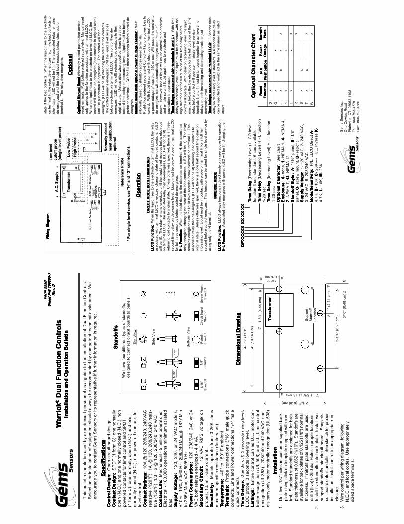
Op
erat
ion
Op
erat
ion
Op
erat
ion
Op
erat
ion
Op
erat
ion
Op
tio
nal
Op
tio
nal
Op
tio
nal
Op
tio
nal
Op
tio
nal
DIR
EC
T M
OD
E B
OT
H F
UN
CT
ION
SD
IRE
CT
MO
DE
BO
TH
FU
NC
TIO
NS
DIR
EC
T M
OD
E B
OT
H F
UN
CT
ION
SD
IRE
CT
MO
DE
BO
TH
FU
NC
TIO
NS
DIR
EC
T M
OD
E B
OT
H F
UN
CT
ION
SL
LC
O F
un
ctio
nL
LC
O F
un
ctio
nL
LC
O F
un
ctio
nL
LC
O F
un
ctio
nL
LC
O F
un
ctio
n:::: :
Whe
n th
e liq
uid
rises
to th
e el
ectr
ode
on te
rmin
al L
LCO
, the
rel
ayas
soci
ated
with
ter
min
al L
LCO
ene
rgiz
es,
chan
ging
sta
te o
f th
e lo
ad c
onta
cts.
(L
ED
will
be
lit).
T
he r
elay
rem
ains
ene
rgiz
ed u
ntil
the
liqui
d le
vel r
eced
es b
elow
ele
ctro
deon
term
inal
LLC
O.
The
ass
ocia
ted
rela
y th
en d
e-en
ergi
zes,
(LE
D w
ill n
ot b
e lit
)re
turn
ing
load
con
tact
s to
orig
inal
sta
te.
Unl
ess
othe
rwis
e sp
ecifi
ed,
ther
e is
a t
hree
-se
cond
tim
e de
lay
on d
ecre
asin
g le
vel.
Liq
uid
mus
t be
belo
w p
robe
on
term
inal
LLC
Ofo
r fu
ll th
ree
seco
nds
befo
re c
ontr
ol d
e-en
ergi
zes.
H-L
Fu
nct
ion
H-L
Fu
nct
ion
H-L
Fu
nct
ion
H-L
Fu
nct
ion
H-L
Fu
nct
ion
:::: : W
hen
the
liqui
d ris
es t
o th
e el
ectr
ode
on t
erm
inal
H,
the
asso
ciat
edre
lay
ener
gize
s, c
hang
ing
the
stat
e of
the
load
con
tact
s.
(LE
D w
ill b
e lit
).
The
rel
ayre
mai
ns e
nerg
ized
unt
il th
e liq
uid
leve
l rec
edes
bel
ow e
lect
rode
on
term
inal
L.
The
asso
ciat
ed r
elay
then
de-
ener
gize
s, (
LED
will
not
be
lit)
retu
rnin
g lo
ad c
onta
cts
toor
igin
al s
tate
. U
nles
s ot
herw
ise
spec
ified
, the
re is
a o
ne h
alf s
econ
d tim
e de
lay
onin
crea
sing
leve
l. L
iqui
d m
ust b
e in
con
tact
with
pro
be o
n te
rmin
al H
for
a fu
ll ha
lfse
cond
bef
ore
cont
rol e
nerg
izes
. T
his
func
tion
can
be w
ired
for
sing
le le
vel s
ervi
ce b
yus
ing
only
the
H te
rmin
al.
TTTT Tim
e D
elay
im
e D
elay
im
e D
elay
im
e D
elay
im
e D
elay
(D
ecre
asin
g Le
vel)
LLC
O le
vel
func
tion
3 se
c st
anda
rd,
6 se
c av
aila
ble.
TTTT Tim
e D
elay
ime
Del
ayim
e D
elay
ime
Del
ayim
e D
elay
(D
ecre
asin
g Le
vel)
H -
L f
unct
ion
1-20
sec
.TTTT T
ime
Del
ayim
e D
elay
ime
Del
ayim
e D
elay
ime
Del
ay (
Incr
easi
ng L
evel
) H
- L
fun
ctio
n1-
20 s
ecO
pti
on
al C
har
acte
rO
pti
on
al C
har
acte
rO
pti
on
al C
har
acte
rO
pti
on
al C
har
acte
rO
pti
on
al C
har
acte
r:
See
cha
rtE
ncl
osu
reE
ncl
osu
reE
ncl
osu
reE
ncl
osu
reE
ncl
osu
re:
0 0 0 0 0-
none
, 1111 1-
NE
MA
1,
4 4 4 4 4-
NE
MA
4,
7777 7- N
EM
A 7
, 12121
212 12
- N
EM
A 1
2S
tan
do
ff S
tyle
:S
tan
do
ff S
tyle
:S
tan
do
ff S
tyle
:S
tan
do
ff S
tyle
:S
tan
do
ff S
tyle
: AAAA A
- 1/
16"
pane
l, BBBB B
- 1/
8"pa
nel,
C C C C C-
scre
w m
ount
, DDDD D
- re
trof
itS
up
ply
VS
up
ply
VS
up
ply
VS
up
ply
VS
up
ply
Vo
ltag
e:o
ltag
e:o
ltag
e:o
ltag
e:o
ltag
e:
1- 1
20 V
AC
, 2-
240
VA
C,
3- 2
4 V
AC
, 8-
208
/240
VA
CM
od
e/S
ensi
tivi
ty:
Mo
de/
Sen
siti
vity
:M
od
e/S
ensi
tivi
ty:
Mo
de/
Sen
siti
vity
:M
od
e/S
ensi
tivi
ty:
H/L
, LL
CO
Dir
ect
A A A A A-
4.7K
, BBBB B
- 10
K,
CCCC C-
26K
----
H
/L,
Inve
rse
KKKK K-
4.7K
, L L L L L
- 10
K,
MMMM M-
26K
DF
XX
XX
X X
X X
X X
XD
FX
XX
XX
XX
XX
XX
DF
XX
XX
X X
X X
X X
XD
FX
XX
XX
XX
XX
XX
DF
XX
XX
X X
X X
X X
X
Op
tio
nal
Man
ual
Res
etO
pti
on
al M
anu
al R
eset
Op
tio
nal
Man
ual
Res
etO
pti
on
al M
anu
al R
eset
Op
tio
nal
Man
ual
Res
et (
Nor
mal
ly c
lose
d pu
shbu
tton
acro
ssre
set
term
inal
s.
Pus
hbut
ton
orde
red
sepa
rate
ly):
M
anua
l res
eton
ly a
pplie
s to
the
fun
ctio
n as
soci
ated
with
ter
min
al L
LCO
.W
hen
the
liqui
d ris
es t
o th
e el
ectr
ode
on t
erm
inal
LLC
O,
the
cont
rol w
ill r
emai
n de
-ene
rgiz
ed (
load
con
tact
s in
orig
inal
sta
te)
until
the
push
butto
n is
dep
ress
ed.
The
con
trol
will
then
ener
gize
, (LE
D w
ill b
e lit
) ch
angi
ng th
e st
ate
of th
e co
ntac
ts.
The
con
trol
rem
ains
ene
rgiz
ed u
ntil
the
liqui
d le
vel r
eced
esbe
low
ele
ctro
de o
n te
rmin
al L
LCO
. T
he c
ontr
ol th
en d
e-en
ergi
zes,
(LE
D w
ill g
o of
f) r
etur
ning
load
con
tact
s to
thei
ror
igin
al s
tate
. U
nles
s ot
herw
ise
spec
ified
, the
re is
a th
ree
seco
nd ti
me
dela
y on
dec
reas
ing
leve
l. L
iqui
d m
ust b
e be
low
prob
e on
term
inal
LLC
O fo
r fu
ll th
ree
seco
nds
befo
re c
ontr
ol d
e-en
ergi
zes.
Man
ual
Res
et w
ith
op
tio
nal
Po
wer
Ou
tag
e F
eatu
re:
Man
ual
Res
et w
ith
op
tio
nal
Po
wer
Ou
tag
e F
eatu
re:
Man
ual
Res
et w
ith
op
tio
nal
Po
wer
Ou
tag
e F
eatu
re:
Man
ual
Res
et w
ith
op
tio
nal
Po
wer
Ou
tag
e F
eatu
re:
Man
ual
Res
et w
ith
op
tio
nal
Po
wer
Ou
tag
e F
eatu
re:
Res
et(N
orm
ally
clo
sed
push
butto
n ac
ross
res
et t
erm
inal
s.P
ushb
utto
n or
dere
d se
para
tely
) C
ontr
ol w
ill ig
nore
pow
er lo
ss to
cont
rol.
With
liqu
id in
con
tact
with
ele
ctro
de o
n te
rmin
al L
LCO
,a
pow
er o
utag
e of
less
than
250
m s
ec. W
ill c
ause
the
cont
rol t
ode
-ene
rgiz
e, b
ut w
ill a
utom
atic
ally
ene
rgiz
e up
on r
etur
n of
pow
er.
How
ever
, los
s of
liqu
id w
ill c
ause
con
trol
to d
e-en
ergi
zean
d re
mai
n so
unt
il liq
uid
agai
n ris
es to
ele
ctro
de a
ndpu
shbu
tton
is d
epre
ssed
.TTTT T
ime
Del
ays
asso
ciat
ed w
ith
ter
min
als
H a
nd
Lim
e D
elay
s as
soci
ated
wit
h t
erm
inal
s H
an
d L
ime
Del
ays
asso
ciat
ed w
ith
ter
min
als
H a
nd
Lim
e D
elay
s as
soci
ated
wit
h t
erm
inal
s H
an
d L
ime
Del
ays
asso
ciat
ed w
ith
ter
min
als
H a
nd
L :
:
:
:
:
W
ith t
ime
dela
y on
incr
easi
ng le
vel,
the
liqui
d m
ust b
e in
con
tact
with
the
high
ele
ctro
de fo
r th
e fu
ll du
ratio
n of
the
time
dela
y be
fore
cont
rol w
ill o
pera
te.
With
del
ay o
n de
crea
sing
leve
l, th
e liq
uid
mus
t be
belo
w th
e lo
w e
lect
rode
for
the
full
dura
tion
of th
e tim
ede
lay
befo
re c
ontr
ol w
ill o
pera
te.
In s
ingl
e le
vel s
ervi
ce,
term
inal
s 3
and
4 m
ust
be ju
mpe
red
toge
ther
to
achi
eve
time
dela
ys o
n bo
th in
crea
sing
and
dec
reas
ing
leve
ls o
r ju
stde
crea
sing
leve
l.TTTT T
ime
Del
ays
asso
ciat
ed w
ith
ter
min
al L
LC
Oim
e D
elay
s as
soci
ated
wit
h t
erm
inal
LL
CO
ime
Del
ays
asso
ciat
ed w
ith
ter
min
al L
LC
Oim
e D
elay
s as
soci
ated
wit
h t
erm
inal
LL
CO
ime
Del
ays
asso
ciat
ed w
ith
ter
min
al L
LC
O:::: :
3 S
econ
d tim
ede
lay
on d
ecre
asin
g le
vel i
s st
anda
rd.
A 6
sec
ond
time
dela
yca
n be
spe
cifie
d an
d w
ould
act
in th
e sa
me
man
ner
as li
sted
abov
e.
INV
ER
SE
MO
DE
INV
ER
SE
MO
DE
INV
ER
SE
MO
DE
INV
ER
SE
MO
DE
INV
ER
SE
MO
DE
LL
CO
Fu
nct
ion
LL
CO
Fu
nct
ion
LL
CO
Fu
nct
ion
LL
CO
Fu
nct
ion
LL
CO
Fu
nct
ion
:::: : L
LCO
alw
ays
func
tions
in d
irect
mod
e on
ly s
ee a
bove
for
oper
atio
n.H
-LH
-LH
-LH
-LH
-L F
un
ctio
n F
un
ctio
n F
un
ctio
n F
un
ctio
n F
un
ctio
n:::: :
Ass
ocia
ted
rela
y en
ergi
zes
with
pow
er, (
LED
will
be
lit)
chan
ging
the
stat
e of
the
load
con
tact
s.
Whe
n th
e liq
uid
rises
to
the
elec
trod
eon
term
inal
H, t
he r
elay
de-
ener
gize
s, r
etur
ning
load
con
tact
s to
shel
f sta
te.
(LE
D w
ill n
ot b
e lit
).
The
ass
ocia
ted
rela
y re
mai
nsde
-ene
rgiz
ed u
ntil
the
liqui
d le
vel r
eced
es b
elow
ele
ctro
de o
nte
rmin
al L
. T
he r
elay
then
ene
rgiz
es.
x x x x x x x x
D G J K L R S T W
Res
etR
eset
Res
etR
eset
Res
etF
un
ctio
nF
un
ctio
nF
un
ctio
nF
un
ctio
nF
un
ctio
n
x x x x
N.C
.N
.C.
N.C
.N
.C.
N.C
.P
ush
bu
tto
nP
ush
bu
tto
nP
ush
bu
tto
nP
ush
bu
tto
nP
ush
bu
tto
n
x x x x
Po
wer
Po
wer
Po
wer
Po
wer
Po
wer
Ou
tag
eO
uta
ge
Ou
tag
eO
uta
ge
Ou
tag
e
x x x x x
Ret
rofi
tR
etro
fit
Ret
rofi
tR
etro
fit
Ret
rofi
tP
late
Pla
teP
late
Pla
teP
late
Op
tio
nal
Ch
arac
ter
Ch
art
Op
tio
nal
Ch
arac
ter
Ch
art
Op
tio
nal
Ch
arac
ter
Ch
art
Op
tio
nal
Ch
arac
ter
Ch
art
Op
tio
nal
Ch
arac
ter
Ch
art
WWWW Wir
ing
Dia
gra
mir
ing
Dia
gra
mir
ing
Dia
gra
mir
ing
Dia
gra
mir
ing
Dia
gra
m
Gem
s S
enso
rs I
nc.
On
e C
ow
les
Ro
ad
Pla
invi
lle,
CT
0
60
62
-11
98
Tel:
86
0-79
3-45
79F
ax:
8
60
-79
3-4
58
0
Sp
ecif
icat
ion
sS
pec
ific
atio
ns
Sp
ecif
icat
ion
sS
pec
ific
atio
ns
Sp
ecif
icat
ion
sC
on
tro
l Des
ign
:C
on
tro
l Des
ign
:C
on
tro
l Des
ign
:C
on
tro
l Des
ign
:C
on
tro
l Des
ign
: O
pen
circ
uit
boar
d de
sign
Co
nta
ct D
esig
n:
Co
nta
ct D
esig
n:
Co
nta
ct D
esig
n:
Co
nta
ct D
esig
n:
Co
nta
ct D
esig
n:
SP
DT
(1
form
C):
one
nor
mal
lyop
en (
N.O
.) a
nd o
ne n
orm
ally
clo
sed
(N.C
.),
non
pow
ered
con
tact
s fo
r lim
it co
ntro
l and
SP
DT
(1 f
orm
C):
one
nor
mal
ly o
pen
(N.O
.) a
nd o
neno
rmal
ly c
lose
d (N
.C.)
, non
pow
ered
con
tact
s fo
rle
vel c
ontr
olC
on
tact
Rat
ing
s:C
on
tact
Rat
ing
s:C
on
tact
Rat
ing
s:C
on
tact
Rat
ing
s:C
on
tact
Rat
ing
s: 1
0A @
120
, 208
/240
, 240
VA
Cre
sist
ive
(120
°F),
1A
@ 1
20,
208/
240,
240
resi
s-tiv
e (1
50°F
), 1
/3 H
p @
120
, 208
/240
, 240
VA
CC
on
tact
Lif
e:C
on
tact
Lif
e:C
on
tact
Lif
e:C
on
tact
Lif
e:C
on
tact
Lif
e: M
echa
nica
l - 5
mill
ion
oper
atio
nsE
lect
rica
l - 1
00,0
00 o
pera
tions
min
imum
at
rate
dlo
adS
up
ply
VS
up
ply
VS
up
ply
VS
up
ply
VS
up
ply
Vo
ltag
e:o
ltag
e:o
ltag
e:o
ltag
e:o
ltag
e:
120,
240
, or
24
VA
C m
odel
s,+
10%
, -15
%, 5
0/60
Hz.
208
/240
Mod
el:
187V
Min
to 2
55V
Max
, VA
C 5
0/60
Hz
Po
wer
Co
nsu
mp
tio
n:
Po
wer
Co
nsu
mp
tio
n:
Po
wer
Co
nsu
mp
tio
n:
Po
wer
Co
nsu
mp
tio
n:
Po
wer
Co
nsu
mp
tio
n:
120
, 20
8/24
0, 2
40,
or 2
4V
AC
bot
h re
lays
ene
rgiz
ed -
4.4
VA
.S
eco
nd
ary
Cir
cuit
:S
eco
nd
ary
Cir
cuit
:S
eco
nd
ary
Cir
cuit
:S
eco
nd
ary
Cir
cuit
:S
eco
nd
ary
Cir
cuit
: 1
2 V
AC
RM
S v
olta
ge
on
prob
es, 1
.5 m
illi-
amp
curr
ent.
Sen
siti
vity
:S
ensi
tivi
ty:
Sen
siti
vity
:S
ensi
tivi
ty:
Sen
siti
vity
: M
odel
s op
erat
e fr
om 0
-26K
ohm
sm
axim
um s
peci
fic r
esis
tanc
e (f
acto
ry s
et)
TTTT T em
per
atu
re:
emp
erat
ure
:em
per
atu
re:
emp
erat
ure
:em
per
atu
re:
-40
° to
150
° F
am
bien
tTTTT T e
rmin
als:
erm
inal
s:er
min
als:
erm
inal
s:er
min
als:
P
robe
con
nect
ions
3/1
6" m
ale
quic
kco
nnec
ts,
Line
and
Pow
er c
onne
ctio
ns 1
/4"
mal
equ
ick
conn
ects
TTTT Tim
e D
elay
s:im
e D
elay
s:im
e D
elay
s:im
e D
elay
s:im
e D
elay
s: S
tand
ard,
0.5
sec
onds
ris
ing
leve
l,LL
CO
pro
be, 3
sec
onds
low
erin
g le
vel.
Lis
tin
gs:
Lis
tin
gs:
Lis
tin
gs:
Lis
tin
gs:
Lis
tin
gs:
E
ntir
e co
ntro
l ca
rrie
s U
.L.
mot
or c
on-
trol
ler
reco
gniti
on (
UL
508)
and
U.L
. Lim
it co
ntro
lre
cogn
ition
(U
L 35
3).
208/
240
and
240
VA
C m
od-
els
carr
y on
ly m
otor
con
trol
ler r
ecog
nitio
n (U
L 50
8)
Inst
alla
tio
nIn
stal
lati
on
Inst
alla
tio
nIn
stal
lati
on
Inst
alla
tio
n1.
Dril
l fiv
e .1
87 h
oles
in c
usto
mer
sup
plie
d ba
ckpl
ate
usin
g st
ick
on te
mpl
ate
supp
lied
with
con
-tr
ol.
Sta
ndar
d st
ando
ffs a
re d
esig
ned
for
back
plat
e th
ickn
ess
of 0
.062
(1/
16")
. S
tand
offs
are
avai
labl
e fo
r bac
k pl
ates
of 0
.125
(1/8
") n
omin
alth
ickn
ess.
If
retr
ofit
plat
e st
ando
ffs a
re u
sed,
drill
5 (f
ive)
0.2
50 d
ia. H
oles
in p
rope
r loc
atio
ns.
2.In
stal
l fiv
e st
ando
ffs in
to b
ack
plat
e. I
nsta
ll tw
osu
ppor
t st
ando
ffs in
to c
ircui
t bo
ard.
S
nap
cir-
cuit
boar
d on
to s
tand
offs
. S
ee s
ketc
h fo
r pro
per
inst
alla
tion.
Ins
tall
cont
rol i
n an
app
ropr
iate
en-
clos
ure.
3.
Wire
con
trol
per
wiri
ng d
iagr
am, f
ollo
win
g
N
.E.C
. and
loca
l cod
es.
Use
app
ropr
iate
ly
si
zed
spad
e te
rmin
als.
Thi
s bu
lletin
sho
uld
be u
sed
by e
xper
ienc
ed p
erso
nnel
as
a gu
ide
to th
e in
stal
latio
n of
Dua
l Fun
ctio
n C
ontr
ols.
Sel
ectio
n or
inst
alla
tion
of e
quip
men
t sho
uld
alw
ays
be a
ccom
pani
ed b
y co
mpe
tent
tech
nica
l ass
ista
nce.
We
enco
urag
e yo
u to
con
tact
Gem
s S
enso
rs o
r its
rep
rese
ntat
ive
if fu
rthe
r in
form
atio
n is
req
uire
d.
We
have
fou
r di
ffere
nt t
ypes
of
stan
doffs
,de
sign
ed t
o co
nnec
t ci
ruci
t bo
ards
to
pane
ls
Top
Vie
w
Sid
e V
iew
Bot
tom
Vie
w
1/16
”S
tand
off
1/8”
Sta
ndof
fR
etro
fitS
tand
off
Cir
cuit
Bo
ard
Sta
ndof
fS
cre
w M
ou
nt
Sta
ndof
f
1/16
”1/
8”
Sta
nd
off
sS
tan
do
ffs
Sta
nd
off
sS
tan
do
ffs
Sta
nd
off
s
Dim
ensi
on
al D
raw
ing
Dim
ensi
on
al D
raw
ing
Dim
ensi
on
al D
raw
ing
Dim
ensi
on
al D
raw
ing
Dim
ensi
on
al D
raw
ing
à
TTTT Tra
nsf
orm
erra
nsf
orm
erra
nsf
orm
erra
nsf
orm
erra
nsf
orm
er
à
à
Su
pp
ort
Sta
nd
off
Lo
catio
n
à
à
1-3/
4” (
4.44
cm
)
4” (
10.1
6 C
M)
4-3/
8” (
11.1
1
1-5/8” (4.13 cm)à
2-1/2” (6.35 cm)
1” (
2.54
cm
)
à
à
3-1/
4” (
8.25
cm
) 3/16
” (0
.48
cm) à
à11/16”(1.75 cm)
à
à
WWWW War
rick
arri
ckar
rick
arri
ckar
rick
®®®® ® D
ual
Fu
nct
ion
Co
ntr
ols
Du
al F
un
ctio
n C
on
tro
ls D
ual
Fu
nct
ion
Co
ntr
ols
Du
al F
un
ctio
n C
on
tro
ls D
ual
Fu
nct
ion
Co
ntr
ols
Inst
alla
tio
n a
nd
Op
erat
ion
Bu
llet
inIn
stal
lati
on
an
d O
per
atio
n B
ull
etin
Inst
alla
tio
n a
nd
Op
erat
ion
Bu
llet
inIn
stal
lati
on
an
d O
per
atio
n B
ull
etin
Inst
alla
tio
n a
nd
Op
erat
ion
Bu
llet
in
Fo
rm 2
22B
Fo
rm 2
22B
Fo
rm 2
22B
Fo
rm 2
22B
Fo
rm 2
22B
Sh
eet
P/N
100
205-
1S
hee
t P
/N 1
0020
5-1
Sh
eet
P/N
100
205-
1S
hee
t P
/N 1
0020
5-1
Sh
eet
P/N
100
205-
1R
evR
evR
evR
evR
ev.
D.
D.
D.
D.
D
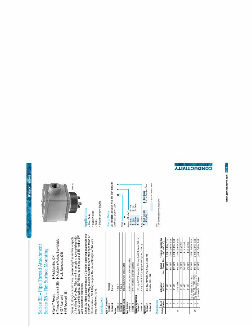
ww
w.g
emss
enso
rs.c
om
E-16
WAR
RICK
® F
ITTI
NGS
XX
3E
Serie
s3E
Num
ber o
f Pro
bes1
1 –
One
2 –
Two
3 –
Thre
e4
– Fo
ur
Body
Mat
eria
lA
– Ca
st Ir
on (3
E)PV
C (3
N)B
– Re
d Br
ass
C –
316
Stai
nles
s St
eel
5 –
Five
6 –
Six
7 –
Seve
n
3N
– St
anda
rd p
art n
umbe
rs
seireSfo
.oNseborP
tnemhcattA
lesseVot
tiudnoCeziS
daerhTssoB
eziSgnisuoHlani
mreT)˝H
x˝D
x˝
W(
E3
1TPN
˝1TPN
˝2/14/1-2
x4/1-2
x4/1-2
2TPN
˝2TPN
˝2/18/3-2
x4/1-3
x4/1-3
3TPN
˝2TPN
˝2/18/3-2
x4/1-3
x4/1-3
4TPN
˝2/1-2TPN
˝2/18/3-2
x4/1-3
x4/1-3
5TPN
˝3TPN
˝4/32/1-2
x4
x4
6TPN
˝3TPN
˝4/32/1-2
x4
x4
7TPN
˝3TPN
˝4/32/1-2
x4
x4
N3
1˝2/1-1,daptalf
erauqs˝4/1-2
deruceslessevfopot
nieloh.aid
ehttas
wercsenihca
m01#
htiw
erauqs˝2/1-1
afosrenroc
TPN˝2/1
4/1-2x
4/1-2x
4/1-2
2TPN
˝2/18/3-2
x4/1-3
x4/1-3
3TPN
˝2/18/3-2
x4/1-3
x4/1-3
Seri
es 3
E –
Pipe
Thr
ead
Att
achm
ent
Seri
es 3
N –
Fla
t Sur
face
Mou
ntin
g
� Up
to 7
Pro
bes
� Fl
at M
ount
ing
(3N)
� Th
read
ed A
ttach
men
t (3E
) �
Avai
labl
e in
Var
ious
Bod
y M
etal
s�
CSA
Appr
oved
�
U.L.
Rec
ogni
zed
(3E)
� FM
App
rove
d (3
E)
Serie
s 3E
fi tti
ngs
are
cast
met
al, p
ress
ure-
tight
ass
embl
ies
capa
ble
of h
andl
ing
1-7
prob
es. A
ttach
men
t to
vess
els
is a
ccom
plis
hed
with
ex
tern
al p
ipe
thre
adin
g. 3
E Fi
tting
s re
quire
the
use
of 3
R rig
id o
r 3W
w
ire s
uspe
nded
ele
ctro
des.
Serie
s 3N
fi tti
ngs
acco
mm
odat
e 1-
3 pr
obes
ope
ratin
g at
atm
osph
eric
pr
essu
re. T
he a
ssem
bly
mou
nts
on a
fl at
sur
face
ato
p op
en ta
nks
or
clos
ed v
esse
ls. 3
N Fi
tting
s re
quire
the
use
of 3
R rig
id o
r 3W
wire
su
spen
ded
elec
trode
s.
Spec
ifi ca
tions
Type
of C
onne
ctio
n
Serie
s 3E
Th
read
ed
Serie
s 3N
Br
acke
tPr
obes
Se
ries
3E
1 th
ru 7
Se
ries
3N
1 th
ru 3
Term
inal
Hou
sing
Di
e ca
st a
lum
inum
, epo
xy c
oate
dBo
dy M
ater
ial
Se
ries
3E
Cast
iron
, red
bra
ss, 3
16 s
tain
less
ste
el
Serie
s 3N
PV
C, re
d br
ass,
316
sta
inle
ss s
teel
Pres
sure
/Tem
pera
ture
Se
ries
3E
125
psig
@ 3
53°F
(cas
t iro
n); 2
50 p
sig
@ 4
06°F
(bra
ss, 3
16 s
.s.)
Se
ries
3N
0 ps
ig @
150
°F (P
VC);
0 ps
ig @
500
°F (b
rass
, 316
s.s
.)Ap
prov
als
Se
ries
3E
U.L.
File
# M
P248
9, V
ol. 1
, Sec
. 2; C
SA; F
M
Serie
s 3N
CS
A Fi
le #
LR1
1644
Dim
ensi
ons
Serie
s 3E
App
licat
ions
• Op
en T
anks
• Cl
osed
Ves
sels
• W
ater
• Di
lute
d Co
rros
ive
Liqu
ids
How
to O
rder
Use
the
Bold
cha
ract
ers
from
the
char
t bel
ow to
co
nstru
ct a
pro
duct
cod
e.
Note
:1.
3N
feat
ures
up
to th
ree
prob
es o
nly.
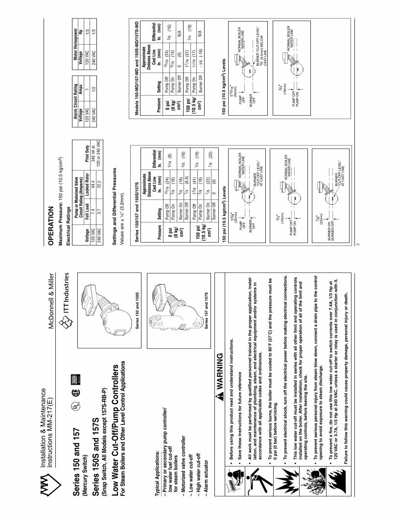
Pum
p or
Mot
orize
d Va
lve
Circ
uit R
atin
g (A
mpe
res)
Volta
geFu
ll Lo
adLo
cked
Rot
orPi
lot D
uty
120
VAC
7.4
44.4
345
VA a
t24
0 VA
C3.
722
.212
0 or
240
VAC
Appr
oxim
ate
Dist
ance
Abo
veCa
st L
ine
Diffe
rent
ial
Setti
ngIn
. (m
m)
In.
(mm
)
Pum
p Of
f15
/16
(24)
5 /16
(8)
Pum
p On
5 /8
(16)
Burn
er O
n5 /
8(1
6)3 /
8(1
6)Bu
rner
Off
1 /4
(6.4
)
Pum
p Of
f13
/8(4
1)3 /
4(1
9)Pu
mp
On5 /
8(1
6)
Burn
er O
n7 /
8(2
2)7 /
8(2
2)Bu
rner
Off
0(0
)
BU
RN
ER
“CU
T-O
FF
LE
VE
L”
AT C
AS
T LI
NE
7 /8"
BU
RN
ER
OF
F
(22m
m)
BU
RN
ER
ON
PU
MP
OF
F
BU
RN
ER
OF
FB
UR
NE
R“C
UT-
OF
F L
EV
EL”
AT
CA
ST
LIN
E
NO
RM
AL
BO
ILE
RW
ATE
R L
INE
13/8
"(3
5mm
)
PU
MP
OF
FP
UM
P O
N
NO
RM
AL
BO
ILE
RW
ATE
R L
INE
3 /4"
(19m
m)
PU
MP
OF
FP
UM
P O
N
NO
RM
AL
BO
ILE
RW
ATE
R L
INE
(19m
m)
3 /4"
PU
MP
OF
F
BU
RN
ER
OF
FB
UR
NE
R “C
UT-
OF
F L
EV
EL”
3 /
8" (
9.5m
m)
BE
LOW
CA
ST
LIN
ENO
RM
AL
BO
ILE
RW
ATE
R L
INE
113 /
16"
(46m
m)
OP
ER
AT
ION
Max
imu
m P
ress
ure
:150
psi
(10
.5 k
g/cm
2 )
Ele
ctri
cal R
atin
gs
Set
tin
gs
and
Dif
fere
nti
al P
ress
ure
s
Val
ues
are
±8
” (3
.2m
m).
Ser
ies
150/
157
and
150
S/1
57S
150
psi
(10
.5 k
g/c
m2 )
Lev
els
150
psi
(10
.5 k
g/c
m2 )
Lev
els
0 ps
i(0
kg/
cm2 )
150
psi
(10.
5 kg
/cm
2 )
Appr
oxim
ate
Dist
ance
Abo
veCa
st L
ine
Diffe
rent
ial
Setti
ngIn
. (m
m)
In.
(mm
)
Pum
p Of
f15
/16
(24)
3 /8
(16)
Pum
p On
9 /16
(14)
Burn
er O
ff0
(0)
N/A
Pum
p Of
f17
/16
(37)
3 /4
(19)
Pum
p On
11/1
6(1
7)
Burn
er O
ff- 3
/8(-
16)
N/A
Mo
del
s 15
0-M
D/1
57-M
D a
nd
150
S-M
D/1
57S
-MD
0 ps
i(0
kg/
cm2 )
150
psi
(10.
5 kg
/cm
2 )
Pres
sure
Pres
sure
Alar
m C
ircui
t Rat
ing
Volta
geAm
ps
120
VAC
1
240
VAC
1/2
Mot
or H
orse
pow
erVo
ltage
Hp
120
VAC
1/3
240
VAC
1/3
2
Ser
ies
150
and
157
(Mer
cury
Sw
itch)
Ser
ies
150S
and
157
S(S
nap
Switc
h,A
ll M
odel
s ex
cept
157
S-R
B-P
)
Low
Wat
er C
ut-O
ff/P
ump
Con
trol
lers
For S
team
Boi
lers
and
Oth
er L
evel
Con
trol A
pplic
atio
ns
Typi
cal A
pplic
atio
ns:
– P
rim
ary
or s
econ
dary
pum
p co
ntro
ller/
low
wat
er fu
el c
ut-o
fffo
r st
eam
boi
lers
– M
otor
ized
val
ve c
ontr
olle
r
– Lo
w w
ater
cut
-off
– H
igh
wat
er c
ut-o
ff
– A
larm
act
uato
r •B
efo
re u
sin
g t
his
pro
du
ct r
ead
an
d u
nd
erst
and
inst
ruct
ion
s.
•S
ave
thes
e in
stru
ctio
ns
for
futu
re r
efer
ence
•A
ll w
ork
mu
st b
e p
erfo
rmed
by
qu
alif
ied
per
son
nel
tra
ined
in t
he
pro
per
ap
plic
atio
n,i
nst
al-
lati
on
,an
d m
ain
ten
ance
of
plu
mb
ing
,ste
am,a
nd
ele
ctri
cal e
qu
ipm
ent
and
/or
syst
ems
in
acco
rdan
ce w
ith
all
app
licab
le c
od
es a
nd
ord
inan
ces.
•To
pre
ven
t se
rio
us
burn
s,th
e b
oile
r m
ust
be
coo
led
to
80˚
F (
27˚C
) an
d t
he
pre
ssu
re m
ust
be
0 p
si (
0 b
ar)
bef
ore
ser
vici
ng
.
•To
pre
ven
t el
ectr
ical
sh
ock
,tu
rn o
ff t
he
elec
tric
al p
ower
bef
ore
mak
ing
ele
ctri
cal c
on
nec
tion
s.
•T
his
low
wat
er c
ut-
off
mu
st b
e in
stal
led
in s
erie
s w
ith
all
oth
er li
mit
an
d o
per
atin
g c
on
tro
ls
inst
alle
d o
n t
he
bo
iler.
Aft
er in
stal
lati
on
,ch
eck
for
pro
per
op
erat
ion
of
all o
f th
e lim
it a
nd
o
per
atin
g c
on
tro
ls,b
efo
re le
avin
g t
he
site
.
•To
pre
ven
t se
rio
us
per
son
al in
jury
fro
m s
team
blo
w d
own
,co
nn
ect
a d
rain
pip
e to
th
e co
ntr
ol
op
enin
g t
o a
void
exp
osu
re t
o s
team
dis
char
ge.
•To
pre
ven
t a
fire
,do
no
t u
se t
his
low
wat
er c
ut-
off
to
sw
itch
cu
rren
ts o
ver
7.4A
,1/3
Hp
at
120
VAC
or
3.7A
,1/3
Hp
at
240
VAC
,un
less
a s
tart
er o
r re
lay
is u
sed
in c
on
jun
ctio
n w
ith
it.
Failu
re t
o f
ollo
w t
his
war
nin
g c
ou
ld c
ause
pro
per
ty d
amag
e,p
erso
nal
inju
ry o
r d
eath
.
WAR
NING
CAUT
ION
!W
AR
NIN
G
Ser
ies
150
and
150
S
Ser
ies
157
and
157
S
Appro
ved
®
Insta
llation &
Main
tenance
Instr
uctions M
M-2
17(E
)
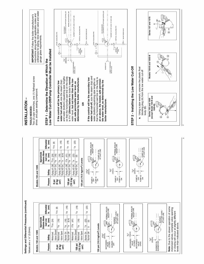
4
If t
he
con
tro
l will
be
the
pri
mar
y lo
ww
ater
fu
el c
ut-
off
,siz
e th
e st
eam
(to
p)an
d w
ater
(bo
ttom
) eq
ualiz
ing
pipe
leng
ths
so t
hat
the
horiz
onta
l cas
t lin
e on
the
bod
yis
1a
”(3
5mm
) b
elo
wth
e bo
iler’s
no
rmal
wat
er le
vel,
but
no
t lo
wer
th
an t
he
low
-es
t,sa
fe p
erm
issi
ble
wat
er le
vel,
asd
eter
min
ed b
y th
e b
oile
r m
anu
fact
ure
r.
OR
If t
he
con
tro
l will
be
the
seco
nd
ary
low
wat
er f
uel
cu
t-o
ff,s
ize
the
stea
m (
top)
and
wat
er (
botto
m)
equa
lizin
g pi
pe le
ngth
s so
that
the
hor
izon
tal c
ast
line
on t
he b
ody
isat
or
abov
e,th
e lo
wes
t,sa
fe p
erm
issi
-b
le w
ater
leve
l,as
det
erm
ined
by
the
bo
iler
man
ufa
ctu
rer.
a.U
sing
a p
ipe
wre
nch,
uns
crew
the
pla
stic
flo
atbl
ocki
ng p
lug
(A)
from
the
low
wat
er c
ut-o
ffbo
dy (
B).
ST
EP
2 -
Inst
allin
g t
he
Lo
w W
ater
Cu
t-O
ff
ST
EP
1 -
Det
erm
ine
the
Ele
vati
on
at W
hic
h t
he
Lo
w W
ater
Cu
t-O
ff/P
um
p C
on
tro
ller
Mu
st b
e In
stal
led
INS
TAL
LA
TIO
N –
TOO
LS
NE
ED
ED
:Tw
o (2
) pi
pe w
renc
hes,
one
(1)
fla
thea
d sc
rew
driv
er,
and
pipe
sea
ling
com
poun
d.
IMP
OR
TAN
T:F
ollo
w th
e bo
iler
man
ufac
ture
r'sin
stru
ctio
ns a
long
with
all
appl
icab
le c
odes
and
ordi
nanc
es fo
r pi
ping
, blo
w d
own
valv
e an
d w
ater
gaug
e gl
ass
requ
irem
ents
.
13/8
"
ST
EA
M E
QU
ALI
ZIN
G P
IPE
VE
RT
ICA
L E
QU
ALI
ZIN
G P
IPE
BLO
W D
OW
N V
ALV
E
NO
RM
AL
BO
ILE
R W
ATE
R L
INE
AS
A P
RIM
AR
YLO
W W
ATE
R C
UT-
OF
F/P
UM
P C
ON
TR
OLL
ER
BU
RN
ER
“CU
T-O
FF
LE
VE
L” A
T C
AS
T LI
NE
LOW
ES
T P
ER
MIS
SIB
LE
WAT
ER
LE
VE
L
(35m
m)
WAT
ER
EQ
UA
LIZ
ING
PIP
E
ST
EA
M E
QU
ALI
ZIN
G P
IPE
VE
RT
ICA
L E
QU
ALI
ZIN
G P
IPE
BLO
W D
OW
N V
ALV
E
AS
A S
EC
ON
DA
RY
LOW
WAT
ER
CU
T-O
FF
/PU
MP
CO
NT
RO
LLE
R
BU
RN
ER
“CU
T-O
FF
LE
VE
L” A
T C
AS
T LI
NE
LOW
ES
T P
ER
MIS
SIB
LE
WAT
ER
LE
VE
L
BU
RN
ER
OF
F
WAT
ER
EQ
UA
LIZ
ING
PIP
E
B AB
A
B
A
Ser
ies
150
and
150
S(e
xcep
t M
od
el 1
50-B
an
d15
0S-B
)
Mo
del
s 15
0-B
an
d 1
50S
-BS
erie
s 15
7 an
d 1
57S
Appr
oxim
ate
Dist
ance
Abo
veCa
st L
ine
Diffe
rent
ial
Setti
ngIn
. (m
m)
In.
(mm
)
Mot
orize
d15
/16
(24)
Valv
e Cl
osed
5 /16
(8)
Mot
orize
d5 /
8(1
6)Va
lve
Open
Burn
er O
n5 /
8(1
6)3 /
8(1
6)Bu
rner
Off
1 /4
(6.4
)
Mot
orize
d13
/8(4
1)
3 /4
(19)
Valv
e Cl
osed
Mot
orize
d5 /
8(1
6)Va
lve
Open
Burn
er O
n7 /
8(2
2)7 /
8(2
2)Bu
rner
Off
0(0
)
BU
RN
ER
“CU
T-O
FF
LE
VE
L”
AT C
AS
T LI
NE
7 /8"
BU
RN
ER
OF
F
(22m
m)
BU
RN
ER
ON
MO
TOR
IZE
DVA
LVE
CLO
SE
D
BU
RN
ER
OF
FB
UR
NE
R“C
UT-
OF
F L
EV
EL”
AT
CA
ST
LIN
E
NO
RM
AL
BO
ILE
RW
ATE
R L
INE
13/8
"(3
5mm
)
MO
TOR
IZE
DVA
LVE
CLO
SE
D
NO
RM
AL
BO
ILE
RW
ATE
R L
INE
(19m
m)
3 /4"
MO
TOR
IZE
DVA
LVE
OP
EN
PU
MP
#1
OF
FP
UM
P #
1O
N
NO
RM
AL
BO
ILE
RW
ATE
R L
INE
(19m
m)
3 /4"
PU
MP
#2
ON
AT C
AS
T LI
NE
7 /8"
PU
MP
#2
ON
(22m
m)
PU
MP
#2
OF
F
PU
MP
#1
OF
FP
UM
P #
2O
NP
UM
P #
2 O
NAT
CA
ST
LIN
E
NO
RM
AL
BO
ILE
RW
ATE
R L
INE
13/8
"(3
5mm
)
Set
tin
gs
and
Dif
fere
nti
al P
ress
ure
s (c
on
tin
ued
)
Val
ues
are
±8
” (3
.2m
m).
No
te:
Due
to
the
slow
er o
pera
tion
of s
ome
mot
oriz
ed v
alve
s, c
ompl
ete
valv
e op
enin
gor
clo
sing
will
occ
ur a
t sl
ight
ly d
iffer
ent
leve
ls t
han
indi
cate
d ab
ove.
Mo
del
s 15
8 an
d 1
58S
150
psi
(10
.5 k
g/c
m2 )
Lev
els
150
psi
(10
.5 k
g/c
m2 )
Lev
els
0 ps
i(0
kg/
cm2 )
150
psi
(10.
5 kg
/cm
2 )
Pres
sure
Appr
oxim
ate
Dist
ance
Abo
veCa
st L
ine
Diffe
rent
ial
Setti
ngIn
. (m
m)
In.
(mm
)
Pum
p #1
Off
15/1
6(2
4)5 /
16(8
)Pu
mp
#1 O
n5 /
8(1
6)
Pum
p #2
Off
5 /8
(16)
3 /8
(16)
Pum
p #2
On
1 /4
(6.4
)
Pum
p #1
Off
13/8
(41)
3 /4
(19)
Pum
p #1
On
5 /8
(16)
Pum
p #2
Off
7 /8
(22)
7 /8
(22)
Pum
p #2
On
0(0
)
Mo
del
s 15
9 an
d 1
59S
0 ps
i(0
kg/
cm2 )
150
psi
(10.
5 kg
/cm
2 )
Pres
sure
3
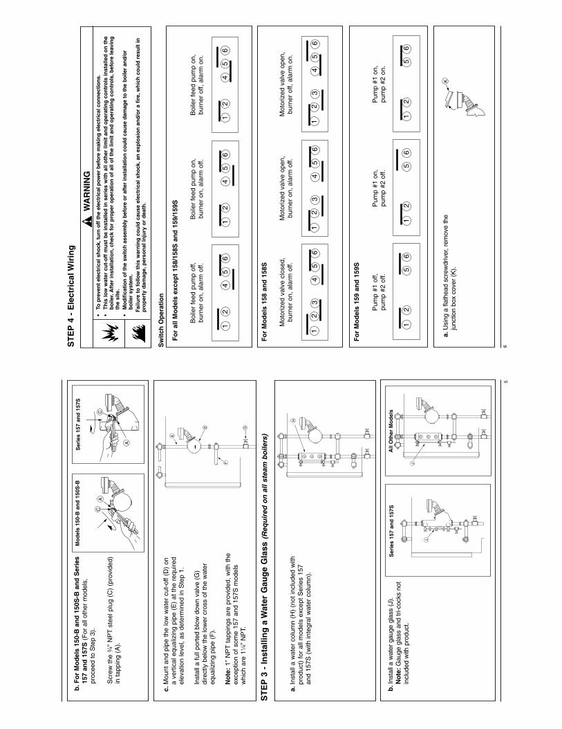
6ST
EP
4 -
Ele
ctri
cal W
irin
g
•To
pre
ven
t el
ectr
ical
sh
ock
,tu
rn o
ff t
he
elec
tric
al p
ower
bef
ore
mak
ing
ele
ctri
cal c
on
nec
tion
s.•
Th
is lo
w w
ater
cu
t-o
ff m
ust
be
inst
alle
d in
ser
ies
wit
h a
ll o
ther
lim
it a
nd
op
erat
ing
co
ntr
ols
inst
alle
d o
n t
he
bo
iler.
Aft
er in
stal
lati
on
,ch
eck
for
pro
per
op
erat
ion
of
all o
f th
e lim
it a
nd
op
erat
ing
co
ntr
ols
,bef
ore
leav
ing
th
e si
te.
•M
od
ifica
tion
of
the
switc
h a
ssem
bly
bef
ore
or
afte
r in
stal
latio
n c
ou
ld c
ause
dam
age
to t
he
bo
iler
and
/or
bo
iler
syst
em.
Failu
re t
o f
ollo
w t
his
war
nin
g c
ou
ld c
ause
ele
ctri
cal s
ho
ck,a
n e
xplo
sio
n a
nd
/or
a fi
re,w
hic
h c
ou
ld r
esu
lt in
pro
per
ty d
amag
e,p
erso
nal
inju
ry o
r d
eath
.
!W
AR
NIN
G
Sw
itch
Op
erat
ion
Fo
r al
l Mo
del
s ex
cep
t 15
8/15
8S a
nd
159
/159
S
Fo
r M
od
els
158
and
158
S
Boi
ler
feed
pum
p of
f,bu
rner
on,
ala
rm o
ff.B
oile
r fe
ed p
ump
on,
burn
er o
n, a
larm
off.
Boi
ler
feed
pum
p on
,bu
rner
off,
ala
rm o
n.
12
4 5
6 1
2 4
5 6
12
4 5
6
Mot
oriz
ed v
alve
clo
sed,
burn
er o
n, a
larm
off.
Mot
oriz
ed v
alve
ope
n,bu
rner
on,
ala
rm o
ff.M
otor
ized
val
ve o
pen,
burn
er o
ff, a
larm
on.
4 5
6 1
2 3
4 5
12
3 4
5 1
2 3
6 6
Fo
r M
od
els
159
and
159
S
Pum
p #1
off,
pum
p #2
off.
Pum
p #1
on,
pum
p #2
off.
Pum
p #1
on,
pum
p #2
on.
12
5 6
12
5 6
12
5 6
Ka.
Usi
ng a
flat
head
scr
ewdr
iver
, rem
ove
the
junc
tion
box
cove
r (K
).
5
CA
A
C
F
G
E
D
c.M
ount
and
pip
e th
e lo
w w
ater
cut
-off
(D)
ona
vert
ical
equ
aliz
ing
pipe
(E
) at
the
req
uire
del
evat
ion
leve
l, as
det
erm
ined
in S
tep
1.
Inst
all a
full
port
ed b
low
dow
n va
lve
(G)
dire
ctly
bel
ow th
e lo
wer
cro
ss o
f the
wat
ereq
ualiz
ing
pipe
(F
).
No
te:
1” N
PT
tapp
ings
are
pro
vide
d, w
ith t
heex
cept
ion
of s
ome
157
and
157S
mod
els
whi
ch a
re 14
” N
PT.
b.F
or
Mo
del
s 15
0-B
an
d 1
50S
-B a
nd
Ser
ies
157
and
157
S(F
or a
ll ot
her
mod
els,
pr
ocee
d to
Ste
p 3)
.
Scr
ew t
he w
” N
PT
stee
l plu
g (C
) (p
rovi
ded)
in t
appi
ng (
A).
Ser
ies
157
and
157
SM
od
els
150-
B a
nd
150
S-B
b.I
nsta
ll a
wat
er g
auge
gla
ss (
J).
Not
e:G
auge
gla
ss a
nd tr
i-coc
ks n
otin
clud
ed w
ith p
rodu
ct.
J
J
Ha.
Inst
all a
wat
er c
olum
n (H
) (n
ot in
clud
ed w
ithpr
oduc
t) f
or a
ll m
odel
s ex
cept
Ser
ies
157
and
157S
(w
ith in
tegr
al w
ater
col
umn)
.
ST
EP
3 -
Inst
allin
g a
Wat
er G
aug
e G
lass
(Req
uir
ed o
n a
ll st
eam
bo
ilers
)
Ser
ies
157
and
157
SA
ll O
ther
Mo
del
s
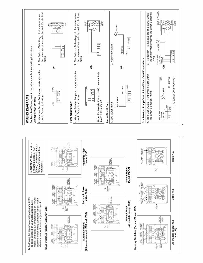
No
te:
For
Mod
els
159
and
159S
, us
e te
rmin
als
5 an
d 6
for
pum
p #2
.
WIR
ING
DIA
GR
AM
SF
or M
otor
ized
Val
ves,
ref
er t
o th
e va
lve
man
ufac
ture
r's w
iring
inst
ruct
ions
.
Lo
w W
ater
Cu
t-O
ff O
nly
1.M
ain
Line
Sw
itch
- F
or b
urne
r ci
rcui
ts w
ithin
the
sw
itch’
s el
ectr
ical
rat
ing.
Pu
mp
Co
ntr
ol O
nly
1.M
ain
Line
Sw
itch
- F
or p
ump
mot
ors
with
in t
he
switc
h’s
elec
tric
al r
atin
g.
1.M
ain
Line
Sw
itch
- F
or b
urne
r ci
rcui
ts w
ithin
th
e sw
itch’
s el
ectr
ical
rat
ing.
2.
Pilo
t S
witc
h -
To
hold
ing
coil
of a
sta
rter
whe
n th
e bu
rner
circ
uit
exce
eds
the
switc
h’s
elec
tric
al
ratin
g.
2. P
ilot
Sw
itch
- T
o ho
ldin
g co
il of
a s
tart
er w
hen
the
pum
p ci
rcui
t ex
ceed
s th
e sw
itch’
s el
ectr
ical
ra
ting.
LIN
ELO
AD
12
45
6
LIN
ELO
AD
12
45
6
12
45
6
ALA
RM
NE
UT
RA
L
HO
T
ALA
RM
NE
UT
RA
L
HO
T
12
45
6
12
45
6
SE
E P
UM
PC
ON
TR
OL
CIR
CU
IT
TO
NE
UT
RA
L
TO
BU
RN
ER
CO
NT
RO
L C
IRC
UIT
HO
TA
LAR
M
12
45
6LO
AD
LIN
E (
3 P
HA
SE
)S
EE
PU
MP
CO
NT
RO
LC
IRC
UIT
ALA
RM
12
45
6LO
AD
LIN
E
12
45
6LO
AD
LIN
E
OR
OR
OR
OR
Co
mb
inat
ion
Pu
mp
Co
ntr
ol,
Lo
w W
ater
Cu
t-O
ff a
nd
Ala
rm
Ala
rm C
ircu
it O
nly
1.Lo
w W
ater
Ala
rm2.
Hig
h W
ater
Ala
rm
2.P
ilot
Sw
itch
- To
hol
ding
coi
l of
a st
arte
r w
hen
the
burn
er c
ircui
t ex
ceed
s th
e sw
itch’
s el
ectr
ical
ratin
g.
8
b.F
ollo
win
g th
e ap
prop
riate
wiri
ng d
iagr
am,
(ref
erto
pag
e 9)
bas
ed o
n yo
ur a
pplic
atio
n re
quire
-m
ents
, an
d us
ing
BX
arm
ored
cab
le o
r T
hinw
all
elec
tric
al m
etal
tub
ing
conn
ecto
r fit
tings
, m
ake
elec
tric
al c
onne
ctio
ns t
o th
e ju
nctio
n bo
x (L
).
PU
MP
SW
ITC
H
PU
MP
CIR
CU
ITT
ER
MIN
ALS
LOW
WAT
ER
CU
T-O
FF
AN
DA
LAR
M S
WIT
CH
ALA
RM
CIR
CU
ITT
ER
MIN
ALS
LOW
WAT
ER
CU
T-O
FF
TE
RM
INA
LS
L
PU
MP
#1
SW
ITC
H
PU
MP
#1
CIR
CU
ITT
ER
MIN
ALS
PU
MP
#2
SW
ITC
H
PU
MP
#2
CIR
CU
ITT
ER
MIN
ALS
L
MO
TOR
IZE
DVA
LVE
SW
ITC
H
MO
TOR
IZE
DVA
LVE
TE
RM
INA
LS
LOW
WAT
ER
CU
T-O
FF
AN
DA
LAR
M S
WIT
CH
ALA
RM
CIR
CU
ITT
ER
MIN
ALS
LOW
WAT
ER
CU
T-O
FF
TE
RM
INA
LS
L
12
34
56
MO
TOR
IZE
DVA
LVE
SW
ITC
H
MO
TOR
IZE
DVA
LVE
TE
RM
INA
LS
LOW
WAT
ER
CU
T-O
FF
AN
DA
LAR
M S
WIT
CH
ALA
RM
CIR
CU
ITT
ER
MIN
ALS
LOW
WAT
ER
CU
T-O
FF
TE
RM
INA
LS
L
12
34
56
PU
MP
SW
ITC
H
PU
MP
CIR
CU
ITT
ER
MIN
ALS
LOW
WAT
ER
CU
T-O
FF
AN
DA
LAR
M S
WIT
CH
ALA
RM
CIR
CU
ITT
ER
MIN
ALS
LOW
WAT
ER
CU
T-O
FF
TE
RM
INA
LS
L
IMP
OR
TAN
T:T
here
mus
t be
a m
inim
um s
pace
of
1/2”
(13m
m)
betw
een
conn
ecto
rfit
tings
and
ele
ctric
al li
vem
etal
par
ts.
Au
tom
atic
Res
et(A
ll m
od
els
exce
pt
158S
an
d 1
59S
)A
uto
mat
ic R
eset
Mo
del
158
S
Man
ual
Res
etM
od
el 1
58S
-M
Au
tom
atic
Res
etM
od
el 1
59S
Man
ual
Res
et(A
ll m
od
els
exce
pt
158S
)
Sn
ap S
wit
ches
(S
erie
s 15
0S a
nd
157
S)
NO
. 1 P
UM
PC
IRC
UIT
NO
. 2 P
UM
PC
IRC
UIT
12
56
L
TOE
LEC
TR
ICVA
LVE
TOLO
W W
ATE
RA
LAR
M
TOLO
W W
ATE
RC
UT-
OF
F
12
34
56
L
PU
MP
SW
ITC
H
PU
MP
CIR
CU
ITT
ER
MIN
ALS
CU
T-O
FF
A
ND
ALA
RM
S
WIT
CH
ALA
RM
CIR
CU
ITT
ER
MIN
ALS
LOW
WAT
ER
CU
T-O
FF
TE
RM
INA
LS
L
(All
mo
del
s ex
cep
t 15
8an
d 1
59)
Mer
cury
Sw
itch
es (
Ser
ies
150
and
157
)
Mo
del
158
Mo
del
159
7
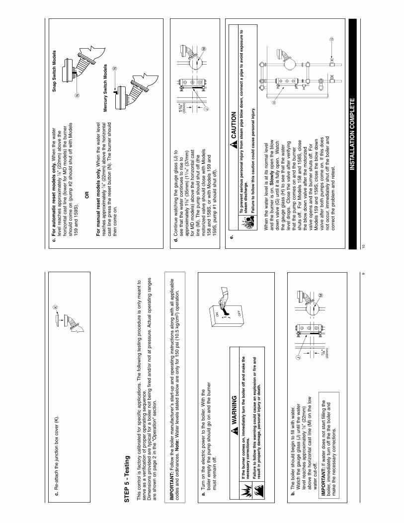
H
G
e.
To p
reve
nt
seri
ou
s p
erso
nal
inju
ry f
rom
ste
am p
ipe
blo
w d
ow
n,c
on
nec
t a
pip
e to
avo
id e
xpo
sure
to
stea
m d
isch
arg
e.
Failu
re t
o f
ollo
w t
his
cau
tio
n c
ou
ld c
ause
per
son
al in
jury
.
!C
AU
TIO
N
Whe
n th
e w
ater
leve
l is
at it
s no
rmal
leve
lan
d th
e bu
rner
is o
n. S
low
lyop
en t
he b
low
dow
n va
lve
(G)
until
it is
ful
ly o
pen.
W
atch
the
gaug
e gl
ass
(H)
to s
ee t
hat
the
wat
erle
vel d
rops
. C
lose
the
val
ve a
fter
verif
ying
that
the
pum
p co
mes
on
and
the
burn
ersh
uts
off.
For
Mod
els
158
and
158S
, cl
ose
the
blow
dow
n va
lve
afte
r th
e m
otor
ized
valv
e op
ens
and
the
burn
er s
huts
off.
For
Mod
els
159
and
159S
, cl
ose
the
blow
dow
nva
lve
afte
r bo
th p
umps
com
e on
. If
this
doe
sno
t oc
cur,
imm
edia
tely
shu
t of
f th
e bo
iler
and
corr
ect
the
prob
lem
and
ret
est. IN
STA
LLAT
ION
CO
MP
LETE
13/8"
M
(35m
m)
J
c.F
or
auto
mat
ic r
eset
mo
del
s o
nly
.Whe
n th
e w
ater
leve
l rea
ches
app
roxi
mat
ely d
” (2
2mm
) ab
ove
the
horiz
onta
l cas
t lin
e (lo
wer
for
MD
mod
els)
the
bur
ner
shou
ld c
ome
on (
pum
p #2
sho
uld
shut
off
with
Mod
els
159
and
159S
).
OR
Fo
r m
anu
al r
eset
mo
del
s o
nly
.Whe
n th
e w
ater
leve
lre
ache
s ap
prox
imat
ely d
” (2
2mm
) ab
ove
the
horiz
onta
lca
st li
ne p
ress
the
res
et b
utto
n (N
). T
he b
urne
r sh
ould
then
com
e on
.
d.
Con
tinue
wat
chin
g th
e ga
uge
glas
s (J
) to
see
that
the
wat
er c
ontin
ues
to r
ise
toap
prox
imat
ely
1a”
(35m
m)
(17 /
16”
(37m
m)
for
MD
mod
els)
abo
ve t
he h
oriz
onta
l cas
tlin
e (M
). T
he p
ump
shou
ld s
hut
off
(the
mot
oriz
ed v
alve
sho
uld
clos
e w
ith M
odel
s15
8 an
d 15
8S,
or w
ith M
odel
s 15
9 an
d15
9S,
pum
p #1
sho
uld
shut
off)
.
10
N
Sn
ap S
wit
ch M
od
els
Mer
cury
Sw
itch
Mo
del
s
N
Kc.
Re-
atta
ch th
e ju
nctio
n bo
x co
ver
(K).
ST
EP
5 -
Tes
tin
g
OF
F
ON
a.Tu
rn o
n th
e el
ectr
ic p
ower
to
the
boile
r. W
ith t
hebo
iler
empt
y th
e pu
mp
shou
ld g
o on
and
the
bur
ner
mus
t re
mai
n of
f.
IMP
OR
TAN
T:F
ollo
w t
he b
oile
r m
anuf
actu
rer’s
sta
rt-u
p an
d op
erat
ing
inst
ruct
ions
alo
ng w
ith a
ll ap
plic
able
code
s an
d or
dina
nces
. N
ote
:W
ater
leve
ls s
tate
d be
low
are
onl
y fo
r 15
0 ps
i (10
.5 k
g/cm
2 ) o
pera
tion.
Thi
s co
ntro
l is
fact
ory
calib
rate
d fo
r sp
ecifi
c ap
plic
atio
ns. T
he f
ollo
win
g te
stin
g pr
oced
ure
is o
nly
mea
nt t
ose
rve
as a
ver
ifica
tion
of p
rope
r op
erat
ing
sequ
ence
.D
imen
sion
s pr
ovid
ed a
re t
ypic
al f
or a
boi
ler
not
bein
g fir
ed a
nd/o
r no
t at
pre
ssur
e. A
ctua
l ope
ratin
g ra
nges
are
show
n on
pag
e 2
in t
he "
Ope
ratio
n" s
ectio
n.
If th
e bu
rner
co
mes
on
,im
med
iate
ly t
urn
th
e b
oile
r o
ff a
nd
mak
e th
en
eces
sary
co
rrec
tion
s.
Failu
re t
o f
ollo
w t
his
war
nin
g c
ou
ld c
ause
an
exp
losi
on
or
fire
an
dre
sult
in p
rop
erty
dam
age,
per
son
al in
jury
or
dea
th.
!W
AR
NIN
G
7 /8"
M
J (22m
m)
b.
The
boi
ler
shou
ld b
egin
to fi
ll w
ith w
ater
.W
atch
the
gau
ge g
lass
(J)
unt
il th
e w
ater
leve
l rea
ches
app
roxi
mat
ely d
” (2
2mm
)ab
ove
the
horiz
onta
l cas
t lin
e (M
) on
the
low
wat
er c
ut-o
ff.
IMP
OR
TAN
T:If
wat
er d
oes
not
star
t fil
ling
the
boile
r, im
med
iate
ly t
urn
off
the
the
boile
r an
dm
ake
the
nece
ssar
y co
rrec
tions
.
9
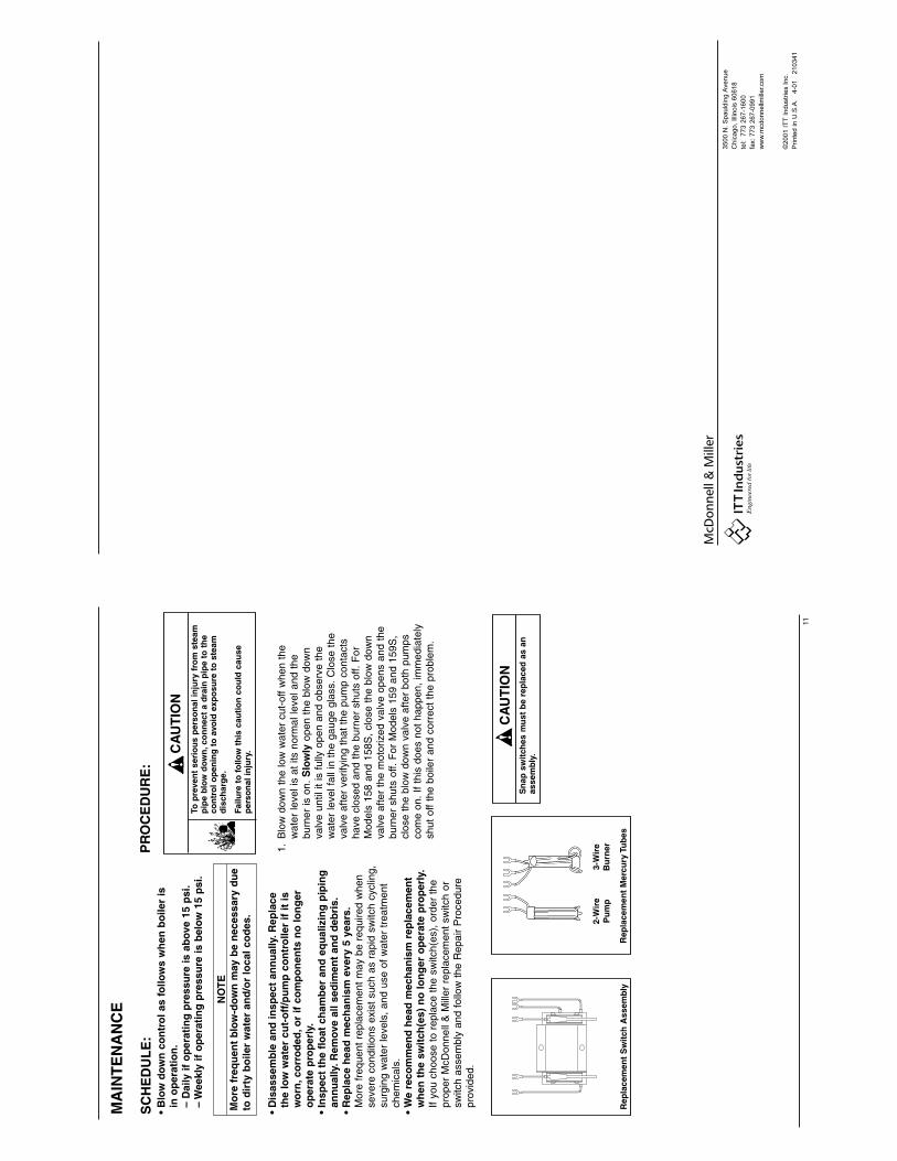
3500 N
. S
pauld
ing A
venue
Chic
ago,
Illin
ois
60618
tel:
77
3 2
67
-16
00
fax:
773 2
67-0
991
ww
w.m
cd
on
ne
llmill
er.co
m
©2001 I
TT
Industr
ies I
nc.
Printe
d in U
.S.A
.
4-0
1
210341
11
MA
INT
EN
AN
CE
SC
HE
DU
LE
:•
Blo
w d
ow
n c
on
tro
l as
follo
ws
wh
en b
oile
r is
in
op
erat
ion
.–
Dai
ly if
op
erat
ing
pre
ssu
re is
ab
ove
15 p
si.
– W
eekl
y if
op
erat
ing
pre
ssu
re is
bel
ow
15
psi
.
•D
isas
sem
ble
an
d in
spec
t an
nu
ally
.Rep
lace
th
e lo
w w
ater
cu
t-o
ff/p
um
p c
on
tro
ller
if it
is
wo
rn,c
orr
od
ed,o
r if
co
mp
on
ents
no
lon
ger
o
per
ate
pro
per
ly.
•In
spec
t th
e fl
oat
ch
amb
er a
nd
eq
ual
izin
g p
ipin
g
ann
ual
ly.R
emov
e al
l sed
imen
t an
d d
ebri
s.•
Rep
lace
hea
d m
ech
anis
m e
very
5 y
ears
.M
ore
freq
uent
rep
lace
men
t m
ay b
e re
quire
d w
hen
seve
re c
ondi
tions
exi
st s
uch
as r
apid
sw
itch
cycl
ing,
su
rgin
g w
ater
leve
ls,
and
use
of w
ater
tre
atm
ent
chem
ical
s.•
We
reco
mm
end
hea
d m
ech
anis
m r
epla
cem
ent
wh
en t
he
swit
ch(e
s) n
o lo
ng
er o
per
ate
pro
per
ly.
If yo
u ch
oose
to
repl
ace
the
switc
h(es
), o
rder
the
pr
oper
McD
onne
ll &
Mill
er r
epla
cem
ent
switc
h or
sw
itch
asse
mbl
y an
d fo
llow
the
Rep
air
Pro
cedu
re
prov
ided
.
PR
OC
ED
UR
E:
1.B
low
dow
n th
e lo
w w
ater
cut
-off
whe
n th
e w
ater
leve
l is
at it
s no
rmal
leve
l and
the
bu
rner
is o
n. S
low
lyop
en t
he b
low
dow
n va
lve
until
it is
ful
ly o
pen
and
obse
rve
the
wat
er le
vel f
all i
n th
e ga
uge
glas
s. C
lose
the
va
lve
afte
r ve
rifyi
ng t
hat
the
pum
p co
ntac
ts
have
clo
sed
and
the
burn
er s
huts
off.
For
M
odel
s 15
8 an
d 15
8S,
clos
e th
e bl
ow d
own
valv
e af
ter
the
mot
oriz
ed v
alve
ope
ns a
nd t
he
burn
er s
huts
off.
For
Mod
els
159
and
159S
, cl
ose
the
blow
dow
n va
lve
afte
r bo
th p
umps
co
me
on.
If th
is d
oes
not
happ
en,
imm
edia
tely
sh
ut o
ff th
e bo
iler
and
corr
ect
the
prob
lem
.
To p
reve
nt
seri
ou
s p
erso
nal
inju
ry f
rom
ste
amp
ipe
blo
w d
ow
n,c
on
nec
t a
dra
in p
ipe
to t
he
con
tro
l op
enin
g t
o a
void
exp
osu
re t
o s
team
dis
char
ge.
Failu
re t
o f
ollo
w t
his
cau
tio
n c
ou
ld c
ause
per
son
al in
jury
.
!C
AU
TIO
N
Sn
ap s
wit
ches
mu
st b
e re
pla
ced
as
anas
sem
bly
.
!C
AU
TIO
N
Rep
lace
men
t S
wit
ch A
ssem
bly
Rep
lace
men
t M
ercu
ry T
ub
es
2-W
ire
Pu
mp
3-W
ire
Bu
rner
NO
TE
Mo
re f
req
uen
t b
low
-do
wn
may
be
nec
essa
ry d
ue
to d
irty
bo
iler
wat
er a
nd
/or
loca
l co
des
.
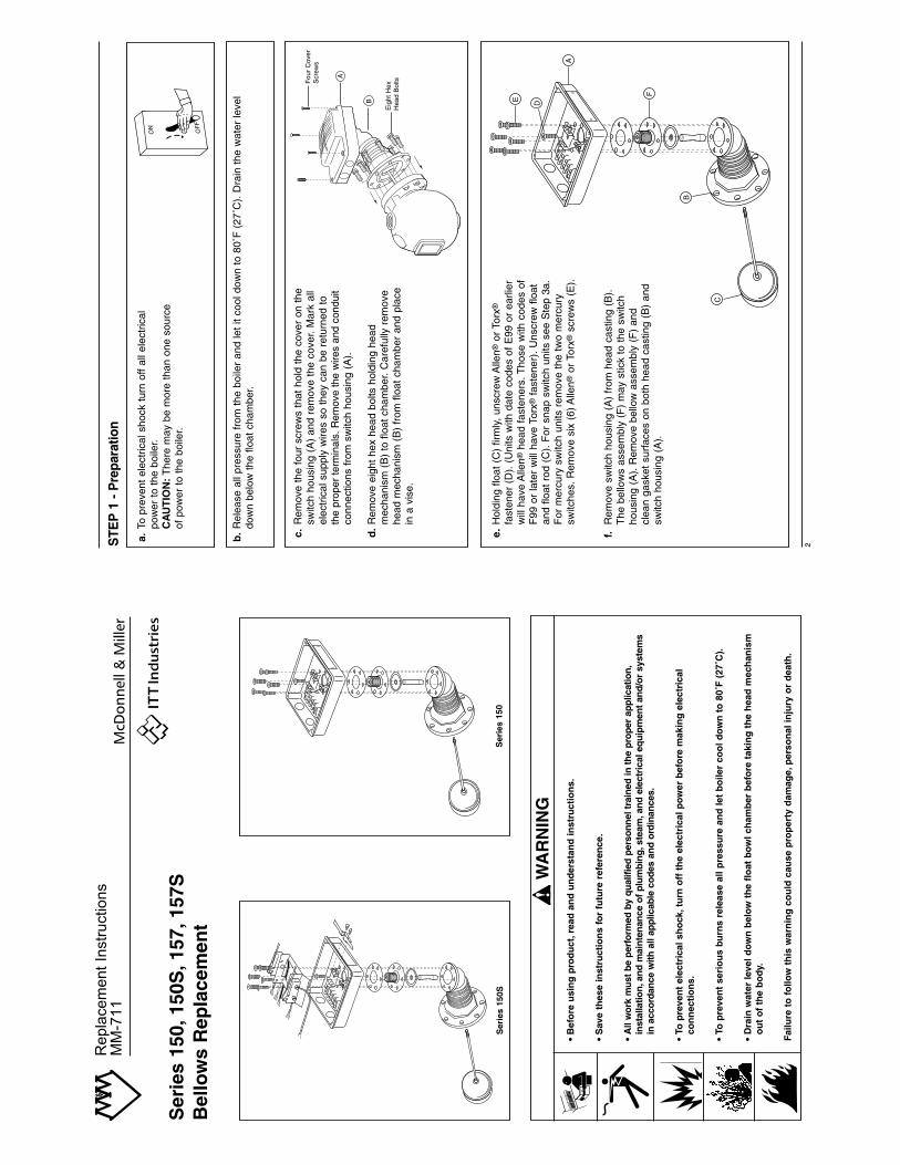
2
OF
F
ON
a.To
pre
vent
ele
ctric
al s
hock
tur
n of
f al
l ele
ctric
al
pow
er t
o th
e bo
iler.
CA
UT
ION
:T
here
may
be
mor
e th
an o
ne s
ourc
e of
pow
er t
o th
e bo
iler.
STE
P 1
- P
repa
ratio
n
b.
Rel
ease
all
pres
sure
fro
m t
he b
oile
r an
d le
t it
cool
dow
n to
80˚
F (
27˚C
). D
rain
the
wat
er le
vel
dow
n be
low
the
flo
at c
ham
ber.
c.R
emov
e th
e fo
ur s
crew
s th
at h
old
the
cove
r on
the
sw
itch
hous
ing
(A)
and
rem
ove
the
cove
r. M
ark
all
elec
tric
al s
uppl
y w
ires
so t
hey
can
be r
etur
ned
to
the
prop
er te
rmin
als.
Rem
ove
the
wire
s an
d co
ndui
t co
nnec
tions
fro
m s
witc
h ho
usin
g (A
).
E D
A
F
C
B
d.
Rem
ove
eigh
t he
x he
ad b
olts
hol
ding
hea
d m
echa
nism
(B
) to
flo
at c
ham
ber.
Car
eful
ly r
emov
e he
ad m
echa
nism
(B
) fr
om f
loat
cha
mbe
r an
d pl
ace
in a
vis
e.
e.H
oldi
ng f
loat
(C
) fir
mly
, un
scre
w A
llen®
or T
orx®
fast
ener
(D
). (
Uni
ts w
ith d
ate
code
s of
E99
or
earli
erw
ill h
ave
Alle
n®he
ad f
aste
ners
. Tho
se w
ith c
odes
of
F99
or
late
r w
ill h
ave
Torx
®fa
sten
er).
Uns
crew
flo
at
and
float
rod
(C
). F
or s
nap
switc
h un
its s
ee S
tep
3a.
For
mer
cury
sw
itch
units
rem
ove
the
two
mer
cury
sw
itche
s. R
emov
e si
x (6
) A
llen®
or T
orx®
scre
ws
(E).
f.R
emov
e sw
itch
hous
ing
(A)
from
hea
d ca
stin
g (B
).
The
bel
low
s as
sem
bly
(F)
may
stic
k to
the
sw
itch
hous
ing
(A).
Rem
ove
bello
w a
ssem
bly
(F)
and
clea
n ga
sket
sur
face
s on
bot
h he
ad c
astin
g (B
) an
d sw
itch
hous
ing
(A).
B
A
Fou
r C
over
Scr
ews
Eig
ht H
exH
ead
Bol
ts
Ser
ies
150,
150S
,157
,157
SB
ello
ws
Rep
lace
men
t
Ser
ies
150
Ser
ies
150S
• B
efo
re u
sin
g p
rod
uct
,rea
d a
nd
un
der
stan
d in
stru
ctio
ns.
• S
ave
thes
e in
stru
ctio
ns
for
futu
re r
efer
ence
.
•A
ll w
ork
mus
t be
per
form
ed b
y qu
alifi
ed p
erso
nnel
tra
ined
in t
he p
rope
r ap
plic
atio
n,in
stal
latio
n,an
d m
aint
enan
ce o
f pl
umbi
ng,s
team
,and
ele
ctri
cal e
quip
men
t an
d/or
sys
tem
s in
acc
orda
nce
with
all
appl
icab
le c
odes
and
ord
inan
ces.
•To
pre
ven
t el
ectr
ical
sh
ock
,tu
rn o
ff t
he
elec
tric
al p
ow
er b
efo
re m
akin
g e
lect
rica
l co
nn
ecti
on
s.
•To
pre
ven
t se
rio
us
burn
s re
leas
e al
l pre
ssu
re a
nd
let
bo
iler
coo
l do
wn
to
80˚
F (
27˚C
).
•D
rain
wat
er le
vel d
ow
n b
elo
w t
he
flo
at b
ow
l ch
amb
er b
efo
re t
akin
g t
he
hea
d m
ech
anis
m
ou
t o
f th
e b
od
y.
Failu
re t
o f
ollo
w t
his
war
nin
g c
ou
ld c
ause
pro
per
ty d
amag
e,p
erso
nal
inju
ry o
r d
eath
.
WAR
NING
CAUT
ION
!W
AR
NIN
G
Repla
cem
ent
Instr
uctions
MM
-711
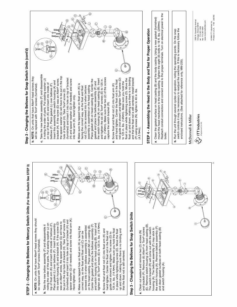
3500 N
. S
pauld
ing A
venue
Chic
ago,
Illin
ois
60618
tel:
77
3 2
67
-16
00
fax:
773 2
67-0
991
ww
w.m
cd
on
ne
llmill
er.co
m
©1999 I
TT
Industr
ies I
nc.
Printe
d in U
.S.A
.
7-9
9
246765
e.S
crew
flo
at a
nd f
loat
rod
(C
) in
to f
loat
arm
(K
) an
d ha
nd t
ight
en.
Cen
ter
the
float
rod
in t
he f
loat
ro
d gu
ide
(not
sho
wn)
and
tig
hten
Tor
x®sc
rew
(D
) to
125
in.
lbs.
(14
N•m
). M
ake
sure
you
hol
d th
e flo
at in
pla
ce w
hile
tig
hten
ing
scre
w (
D).
Mov
e th
e flo
at u
p an
d do
wn,
mak
ing
sure
the
re is
no
bind
ing
and
that
the
float
rod
is s
till c
ente
red.
Inst
all b
rack
et
(P)
usin
g sc
rew
s (N
), t
ight
en t
o 40
in.
lbs.
(4
.5 N
•m).
a.C
lean
the
gas
ket
surf
ace
on h
ead
cast
ing
(B)
and
the
body
cas
ting.
Usi
ng a
new
gas
ket
(fur
nish
ed)
mou
nt t
he h
ead
mec
hani
sm t
o th
e bo
dy c
astin
g. T
ight
en t
he e
ight
(8)
bol
ts t
o 18
ft.
lbs.
(24
N•m
).
Rea
ttach
con
duit
conn
ecto
rs a
nd c
onne
ct w
ires
to t
he p
rope
r te
rmin
als.
Tur
n on
ele
ctric
al p
ower
to
the
boile
r.
STE
P 4
- A
ssem
blin
g th
e H
ead
to th
e B
ody
and
Test
for
Pro
per
Ope
ratio
n
b.
Run
the
uni
t th
roug
h se
vera
l cyc
les
of o
pera
tion,
not
ing
the
oper
atin
g po
ints
. O
n th
e sn
ap
switc
h co
ntro
ls it
may
be
nece
ssar
y to
rea
djus
t th
e sw
itche
s. I
f th
is is
nec
essa
ry f
ollo
w t
he
encl
osed
inst
ruct
ions
. (S
ee a
ttach
ed f
or r
efer
ence
onl
y, M
M-2
35).
d.
Mak
e su
re t
he t
appe
d ho
le o
n flo
at a
rm (
K)
is
faci
ng t
he c
orre
ct w
ay,
so t
he f
loat
and
flo
at
rod
(C)
can
be s
crew
ed in
to it
whe
n be
llow
s as
sem
bly
is a
ssem
bled
on
the
head
cas
ting.
P
lace
gas
ket
(M)
on h
ead
cast
ing
(B).
Cen
ter
the
gask
et a
nd p
lace
the
bel
low
s as
sem
bly
(F)
and
the
switc
h ho
usin
g (A
) on
hea
d ca
stin
g (B
). I
nser
t an
d tig
hten
the
six
(6)
Tor
x®sc
rew
s (E
) to
125
in.
lbs.
(14
N•m
). M
ake
sure
tha
t tw
o (2
) of
the
scr
ews
capt
ure
the
switc
h br
acke
t (R
).
D H
G JK
E
DR
A
B
P
J
C
H
NL F
K
M
c.Ta
ke t
he n
ew b
ello
ws
asse
mbl
y (F
) an
d di
sass
embl
e it
notin
g th
e or
der
of p
arts
. P
ut s
ealin
g w
ashe
r (J
) on
top
of
float
arm
(K
) an
d in
sert
into
insi
de o
f be
llow
s (F
). P
lace
gas
ket
(L)
over
bel
low
s (F
).
Inse
rt t
his
asse
mbl
y in
to s
witc
h ho
usin
g (A
) an
d br
acke
t (H
). I
f th
e sc
rew
(D
) w
as a
n A
llen®
scre
w,
the
spac
er w
ashe
r (G
) w
ill h
ave
to b
e pu
t in
the
top
ho
le o
f br
acke
t (H
). T
ake
Torx
®sc
rew
(D
) (f
urni
shed
) an
d in
sert
it in
to h
ole
on t
op o
f br
acke
t (H
) an
d sp
acer
was
her
(G)
(if n
eede
d) a
nd s
crew
in
to f
loat
arm
(K
). H
and
tight
en o
nly.
Ste
p 3
- Cha
ngin
g th
e B
ello
ws
for
Sna
p S
witc
h U
nits
(con
t’d)
b.
NO
TE
:O
n un
its t
hat
have
Alle
n®he
ad s
crew
s th
ey
will
be
repl
aced
with
Tor
x®sc
rew
s (f
urni
shed
).
3
C
E
DA L F
J K
B
M
HD H
G JK
STE
P 2
- C
hang
ing
the
Bel
low
s fo
r M
ercu
ry S
witc
h U
nits
(For
Sna
p S
witc
h S
ee S
TEP
3)
c.M
ake
sure
tap
ped
hole
on
float
arm
(K
) is
fac
ing
the
corr
ect
way
, so
the
flo
at a
nd f
loat
rod
(C
) ca
n be
sc
rew
ed in
to it
whe
n be
llow
s as
sem
bly
is a
ssem
bled
on
the
hea
d ca
stin
g. P
lace
gas
ket
(M)
on c
astin
g (B
).
Cen
ter
the
gask
et a
nd p
lace
the
bel
low
s as
sem
bly
(F)
and
switc
h ho
usin
g (A
) on
hea
d ca
stin
g (B
). I
nser
t an
d tig
hten
six
(6)
Tor
x®sc
rew
s (E
) to
125
in.
lbs.
(14
N•m
).
d.
Scr
ew f
loat
and
flo
at r
od (
C)
into
flo
at a
rm (
K)
and
hand
tig
hten
. C
ente
r th
e flo
at r
od in
the
flo
at r
od
guid
e (n
ot s
how
n) a
nd t
ight
en T
orx
scre
w (
D)
to
125
in.
lbs.
(14
N•m
). M
ake
sure
you
hol
d th
e flo
at
in p
lace
whi
le t
ight
enin
g sc
rew
(D
). M
ove
the
float
up
and
dow
n, m
akin
g su
re t
here
is n
o bi
ndin
g an
d th
at t
he f
loat
rod
is s
till c
ente
red.
b.
Take
the
new
bel
low
ass
embl
y (F
) an
d di
sass
embl
e it
notin
g th
e or
der
of t
he p
arts
. P
ut s
ealin
g w
ashe
r (J
) on
to
p of
flo
at a
rm (
K)
and
inse
rt in
to in
side
of
bello
ws
(F).
P
lace
gas
ket
(L)
over
bel
low
s (F
). I
nser
t th
is a
ssem
bly
into
sw
itch
hous
ing
(A)
and
brac
ket
(H).
If
the
scre
w (
D)
was
an
Alle
n®sc
rew
, th
e sp
acer
was
her
(G)
will
hav
e to
be
put
in t
he t
op h
ole
of b
rack
et (
H).
Tak
e To
rx®
scre
w (
D)
(fur
nish
ed)
and
inse
rt it
into
hol
e on
top
of b
rack
et (
H)
and
spac
er w
ashe
r(G
) (if
nee
ded)
and
scr
ew in
to f
loat
arm
(K
).H
and
tight
en o
nly.
a.N
OT
E:
On
units
tha
t ha
ve A
llen®
head
scr
ews
they
sho
uld
be r
epla
ced
with
Tor
x®sc
rew
s (f
urni
shed
).
B
C
J
F
A
G
D
P
N
R
E
Ste
p 3
- Cha
ngin
g th
e B
ello
ws
for
Sna
p S
witc
h U
nits
a.C
lean
out
sea
lant
and
rem
ove
two
(2)
scre
ws
(N)
and
brac
ket
(P).
Rem
ove
(6)
Alle
n®or
Tor
x®sc
rew
s (E
). R
emov
e sw
itch
hous
ing
(A)
from
hea
d ca
stin
g (B
).T
he s
witc
h br
acke
t (R
) w
ill c
ome
out
with
the
sw
itch
hous
ing
(A).
The
bel
low
s as
sem
bly
(F)
may
stic
k to
th
e sw
itch
hous
ing
(A).
Rem
ove
bello
w a
ssem
bly
(F)
and
clea
n ga
sket
sur
face
s on
bot
h he
ad c
astin
g (B
) an
d sw
itch
hous
ing
(A).
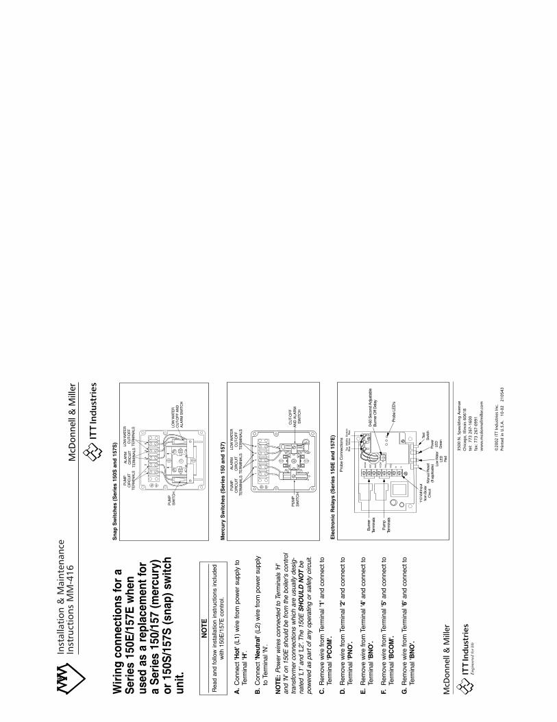
Inst
alla
tion
& M
aint
enan
ceIn
stru
ctio
ns M
M-4
16
Wir
ing
conn
ectio
ns fo
r a
Ser
ies
150E
/157
E w
hen
used
as
a re
plac
emen
t for
a S
erie
s 15
0/15
7 (m
ercu
ry)
or 1
50S
/157
S (s
nap)
sw
itch
unit.
A.
Con
nect
'Hot
'(L1
) w
ire fr
om p
ower
sup
ply
to
Term
inal
'H'.
B.
Con
nect
'Neu
tral
'(L2
) w
ire fr
om p
ower
sup
ply
to T
erm
inal
'N'.
NO
TE:
Pow
er w
ires
conn
ecte
d to
Ter
min
als
'H'
and
'N' o
n 15
0E s
houl
d be
from
the
boile
r's c
ontro
ltra
nsfo
rmer
con
nect
ions
whi
ch a
re u
sual
ly d
esig
-na
ted
'L1'
and
'L2'
.The
150
E S
HO
ULD
NO
Tbe
pow
ered
as
part
of a
ny o
pera
ting
or s
afet
y ci
rcui
t.
C.
Rem
ove
wire
from
Ter
min
al '1
'and
con
nect
to
Term
inal
'PC
OM
'.
D.
Rem
ove
wire
from
Ter
min
al '2
'and
con
nect
to
Term
inal
'PN
O'.
E.
Rem
ove
wire
from
Ter
min
al '4
'and
con
nect
to
Term
inal
'BN
O'.
F.R
emov
e w
ire fr
om T
erm
inal
'5'a
nd c
onne
ct to
Te
rmin
al 'B
CO
M'.
G.
Rem
ove
wire
from
Ter
min
al '6
'and
con
nect
to
Term
inal
'BN
O'.
3500
N. S
paul
ding
Ave
nue
Chi
cago
, Illi
nois
606
18te
l: 7
73 2
67-1
600
fax:
773
267
-099
1w
ww
.mcd
onne
llmill
er.c
om
©20
02 IT
T In
dust
ries
Inc.
Prin
ted
in U
.S.A
. 1
0-02
2
1054
3
NO
TE
Rea
d an
d fo
llow
inst
alla
tion
inst
ruct
ions
incl
uded
with
150
E/1
57E
con
trol
.
PU
MP
SW
ITC
H
PU
MP
CIR
CU
ITT
ER
MIN
ALS
LOW
WAT
ER
CU
T-O
FF
AN
DA
LAR
M S
WIT
CH
ALA
RM
CIR
CU
ITT
ER
MIN
ALS
LOW
WAT
ER
CU
T-O
FF
TE
RM
INA
LS
PU
MP
SW
ITC
H
PU
MP
CIR
CU
ITT
ER
MIN
ALS
CU
T-O
FF
A
ND
ALA
RM
S
WIT
CH
ALA
RM
CIR
CU
ITT
ER
MIN
ALS
LOW
WAT
ER
CU
T-O
FF
TE
RM
INA
LS
BC
OM
BN
C
BN
O
PC
OM
PN
C
PN
O
N HBC
OM
BN
C
BN
O
PC
OM
PN
C
PN
O
N H
60
30
Secs.
060
30
Secs.
0
BC
OM
BN
C
BN
O
PC
OM
PN
C
PN
O
N H
060
30
Secs.
0
Pro
be C
onne
ctio
nsB
otto
mR
edM
iddl
eYe
llow
Top
Blu
e
0-60
Sec
ond
Adj
usta
ble
Bur
ner O
ff D
elay
110
Volt
Inpu
tfro
m B
oile
rC
ircui
tM
anua
l Res
et(If
app
licab
le) Lo
w W
ater
LED
Red
Pow
erLE
DG
reen
Test
Sw
itch
Bur
ner
Term
inal
s
Pum
pTe
rmin
als
BC
OM
BN
C
BN
O
PC
OM
PN
C
PN
O
N H
Pro
be L
ED
's
Ele
ctro
nic
Rel
ays
(Ser
ies
150E
an
d 1
57E
)
Mer
cury
Sw
itch
es (
Ser
ies
150
and
157
)
Sn
ap S
wit
ches
(S
erie
s 15
0S a
nd
157
S)
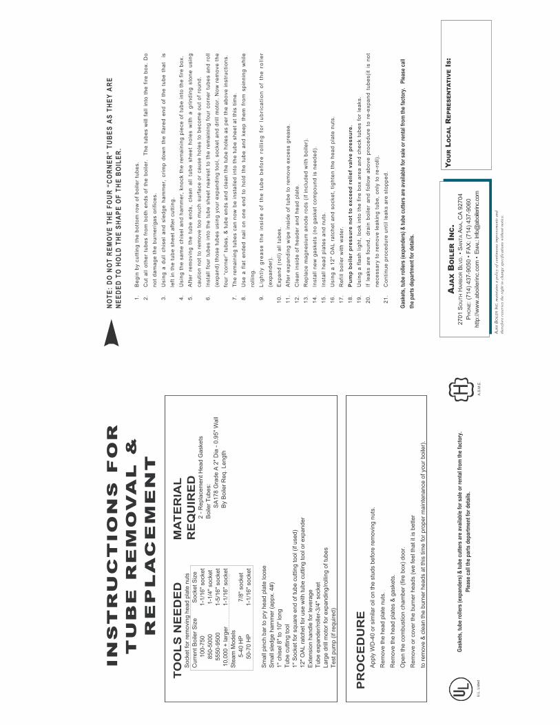
NO
TE
: D
O N
OT
RE
MO
VE
TH
E F
OU
R “
CO
RN
ER
” T
UB
ES
AS
TH
EY
AR
E
NE
ED
ED
TO
HO
LD
TH
E S
HA
PE
OF
TH
E B
OIL
ER
.
1.
Be
gin
by c
utt
ing
th
e b
ott
om
ro
w o
f b
oile
r tu
be
s.
2.
Cu
t a
ll o
the
r tu
be
s f
rom
bo
th e
nd
s o
f th
e b
oile
r.
Th
e t
ub
es w
ill
fall i
nto
th
e f
ire
bo
x.
Do
no
t d
am
ag
e t
he
bu
rne
r/g
as o
rifi
ce
s.
3.
Usin
g a
du
ll c
his
el
an
d s
led
ge
ha
mm
er,
cri
mp
do
wn
th
e f
lare
d e
nd
of
the
tu
be
th
at
is
left
in
th
e t
ub
e s
he
et
aft
er
cu
ttin
g.
4.
Usin
g t
he
sa
me
ch
ise
l a
nd
ha
mm
er,
kn
ock t
he
re
ma
inin
g p
iece
of
tub
e i
nto
th
e f
ire
bo
x.
5.
Aft
er
rem
ov
ing
th
e tu
be
e
nd
s,
cle
an
a
ll tu
be
s
he
et
ho
les
w
ith
a
g
rin
din
g s
ton
e u
sin
g
ca
uti
on
no
t to
re
mo
ve
to
o m
uch
su
rfa
ce
or
ca
use
ho
les t
o b
eco
me
ou
t o
f ro
un
d.
6.
Insta
ll f
ou
r tu
be
s i
nto
th
e t
ub
e s
he
et
ne
are
st
to t
he
re
ma
inin
g f
ou
r co
rne
r tu
be
s a
nd
ro
ll
(exp
an
d)
tho
se
tu
be
s u
sin
g y
ou
r e
xp
an
din
g t
oo
l, s
ocke
t a
nd
dri
ll m
oto
r. N
ow
re
mo
ve
th
e
fou
r “c
orn
er”
tu
be
s,
& t
ub
e e
nd
s a
nd
cle
an
th
e t
ub
e h
ole
s a
s p
er
the
ab
ove
in
str
ucti
on
s.
7.
Th
e r
em
ain
ing
tu
be
s c
an
no
w b
e i
nsta
lle
d i
nto
th
e t
ub
e s
he
et
at
this
tim
e.
8.
Use
a f
lat
en
de
d n
ail o
n o
ne
en
d t
o h
old
th
e t
ub
e a
nd
ke
ep
th
em
fro
m s
pin
nin
g w
hile
rollin
g.
9.
Lig
htl
y g
rea
se
th
e in
sid
e o
f th
e tu
be
b
efo
re ro
llin
g fo
r lu
bri
ca
tio
n o
f th
e ro
lle
r
(exp
an
de
r).
10
.E
xp
an
d (
roll)
all t
ub
es.
11
.A
fte
r e
xp
an
din
g w
ipe
in
sid
e o
f tu
be
to
re
mo
ve
exce
ss g
rea
se
.
12
.C
lea
n i
nsid
e o
f h
ea
de
r a
nd
he
ad
pla
te.
13
.R
ep
lace
ma
gn
esiu
m a
no
de
ro
ds (
if i
nclu
de
d w
ith
bo
ile
r).
14
.In
sta
ll n
ew
ga
ske
ts (
no
ga
ske
t co
mp
ou
nd
is n
ee
de
d).
15
.In
sta
ll h
ea
d p
late
s a
nd
nu
ts.
16
.U
sin
g a
12
" O
AL
ra
tch
et
an
d s
ocke
t, t
igh
ten
th
e h
ea
d p
late
nu
ts.
17
.R
efi
ll b
oile
r w
ith
wa
ter.
18
.P
um
p b
oil
er
pre
ss
ure
no
t to
ex
ce
ed
re
lie
f v
alv
e p
res
su
re.
19
.U
sin
g a
fla
sh
lig
ht,
lo
ok i
nto
th
e f
ire
bo
x a
rea
an
d c
he
ck t
ub
es f
or
lea
ks.
20
.If
le
aks a
re f
ou
nd
, d
rain
bo
ile
r a
nd
fo
llo
w a
bo
ve
pro
ce
du
re t
o r
e-e
xp
an
d t
ub
es(i
t is
no
t
ne
ce
ssa
ry t
o r
em
ove
le
akin
g t
ub
e,
on
ly t
o r
e-r
oll).
21
.C
on
tin
ue
pro
ce
du
re u
nti
l le
aks a
re s
top
pe
d.
Gas
kets
, tu
be
rolle
rs (
exp
and
ers)
& t
ub
e cu
tter
s ar
e av
aila
ble
fo
r sa
le o
r re
nta
l fro
m t
he
fact
ory
. P
leas
e ca
ll
the
par
ts d
epar
tmen
t fo
r d
etai
ls.
YO
UR
LO
CA
LR
EP
RE
SE
NTA
TIV
EIS:
AJAXBOILERINC
. m
ain
tain
s a
po
licy o
f co
nti
nu
ou
s im
pro
vem
en
ts a
nd
there
fore
rese
rves
the r
igh
t to
ch
an
ge s
pecif
ica
tio
ns
wit
ho
ut
no
tice.
AJA
XB
OIL
ER
IN
C.
2701 S
OU
TH
HA
RB
OR
BL
VD. •
SA
NT
AA
NA, C
A 9
2704
PH
ON
E: (7
14)
437-9
050 •
FA
X: (7
14)
437-9
060
http://w
ww
.aboile
rinc.c
om
• E
MA
IL: I
nfo
@aboile
rinc.
com
A.S
.M.E
.U
.L.
Lis
ted
TO
OL
S N
EE
DE
DS
ocket fo
r re
movin
g h
ead p
late
nuts
Curr
ent B
oile
r S
ize
Socket S
ize
100-7
50
1-1
/16"
socket
850-5
000
1-1
/4"
socket
5550-9
500
1-5
/16"
socket
10,0
00 +
larg
er
1-1
/16"
socket
Ste
am
Models
5-4
0 H
P7/8
" socket
50-7
0 H
P
1-1
/16"
socket
Sm
all
pin
ch b
ar
to p
ry h
ead p
late
loose
Sm
all
sle
dge h
am
mer
(appx. 4#)
1"
chis
el 8"
to 1
0"
long
Tube c
uttin
g tool
1"
Socket fo
r square
end o
f tu
be c
uttin
g tool (if used)
12"
OA
L r
atc
het fo
r use w
ith tube c
uttin
g tool or
expander
Exte
nsio
n h
andle
for
levera
ge
Tube e
xpander/
rolle
r-3/4
" socket
Larg
e d
rill
moto
r fo
r expandin
g/r
olli
ng o
f tu
bes
Test pum
p (
if r
equired)
PR
OC
ED
UR
EA
pply
WD
-40 o
r sim
ilar
oil
on the s
tuds b
efo
re r
em
ovin
g n
uts
.
Rem
ove the h
ead p
late
nuts
.
Rem
ove the h
ead p
late
s &
gaskets
.
Open the c
om
bustion c
ham
ber
(fire b
ox)
door.
Rem
ove o
r cover
the b
urn
er
heads (
we feel th
at it is b
etter
to r
em
ove &
cle
an the b
urn
er
heads a
t th
is tim
e for
pro
per
main
tenance o
f your
boile
r).
Gas
kets
, tu
be
rolle
rs (
exp
and
ers)
& t
ub
e cu
tter
s ar
e av
aila
ble
fo
r sa
le o
r re
nta
l fro
m t
he
fact
ory
.
Ple
ase
call
the
par
ts d
epar
tmen
t fo
r d
etai
ls.
IN
ST
RU
CT
IO
NS
F
OR
TU
BE
R
EM
OV
AL
&
RE
PL
AC
EM
EN
T
MA
TE
RIA
L
RE
QU
IRE
D2 -
Repla
cem
ent H
ead G
askets
Boile
r T
ubes:
SA
178 G
rade A
2"
Dia
- 0
.95"
Wall
By B
oile
r R
eq. Length


0
AJAX BOILER INC.2701 S. Harbor Blvd. • Santa Ana, CA 92704 714.437.9050 • Fax 714.437-9060 [email protected]
Copyright 2003 © Ajax Boiler Inc. All rights reserved. Printed in the USA Performance specifications are effective with date of issue and are subject to change without prior notice. The brand and product names contained within this document are trademarks or registered of their respective holders.
SO # Serial No. Model No.
N O T I C E This owners & operation manual provides warnings of risk of harm from improper installation, operation and/or maintenance of Ajax Products. Ajax Boiler, Inc. used ordinary care and complied with UL and ASME Standards in the design and manufacture of Ajax Products. Proper installation, operation and maintenance are covered in the manual supplied with the product. All equipment must comply with local codes.
W A R N I N G THIS PRODUCT CONTAINS CRYSTALLINE SILICA, A CHEMICAL KNOWN TO CAUSE CANCER. CONTAINS NO ASBESTOS.
Rev.3
-3.2
2.20
10