Embed Size (px)
Citation preview

Operating and Installation InstructionsVentilation Hood
To prevent accidents and damage to the appliance, you must readthese instructions before installing the appliance and using it for the firsttime.
en-US M.-Nr. 10 561 080

Contents
2
IMPORTANT SAFETY INSTRUCTIONS ................................................................ 4
Caring for the environment ................................................................................ 13
Guide to the appliance ........................................................................................ 14
Description of functions ..................................................................................... 16Con@ctivity 2.0 function........................................................................................ 17
Operation (Automatic mode) .............................................................................. 18Cooking with Con@ctivity 2.0 (Automatic mode) .................................................. 18Temporarily exiting Automatic mode..................................................................... 20Resuming Automatic mode................................................................................... 20
Operation (Manual mode) ................................................................................... 21Cooking without Con@ctivity 2.0 (Manual mode) ................................................. 21Turning on the blower............................................................................................ 21Selecting the power level ...................................................................................... 21Selecting the Delayed shut down time.................................................................. 21Turning off the blower............................................................................................ 21Turning the overhead lighting on/off...................................................................... 21Power management .............................................................................................. 22
Operation (Automatic and Manual modes) ....................................................... 23Filter saturation indicator....................................................................................... 23
Adjusting the filter saturation indicator for the grease filter.............................. 23Activating/changing the charcoal filter saturation indicator ............................. 24Checking the filter saturation indicator............................................................. 24
Energy-saving tips............................................................................................... 25
Cleaning and care ............................................................................................... 26Stainless steel housing.......................................................................................... 26Grease filters ......................................................................................................... 26OdorFree Charcoal Filter ....................................................................................... 28
Resetting the filter saturation indicator for the charcoal filter .......................... 29Disposing of the OdorFree charcoal filter......................................................... 29
Changing a light bulb ............................................................................................ 30

Contents
3
Installation............................................................................................................ 31Before installation.................................................................................................. 31Installation Instructions ......................................................................................... 31Installation parts .................................................................................................... 32Appliance dimensions ........................................................................................... 34Distance between cooktop and ventilation hood (S)............................................. 35Installation recommendations ............................................................................... 36
Air venting ............................................................................................................ 37Reducing Collar .................................................................................................... 38
Electrical connection .......................................................................................... 39
Activating Con@ctivity 2.0 .................................................................................. 40Installation of the Con@ctivity 2.0 stick................................................................. 40Activating the Con@ctivity 2.0 function................................................................. 40
Activating the ventilation hood......................................................................... 40Activating the cooktop ..................................................................................... 41Activation failed ................................................................................................ 41
Deactivating Con@ctivity 2.0................................................................................. 41
Service and warranty .......................................................................................... 42Location of the data plate ..................................................................................... 42MieleCare .............................................................................................................. 42
Technical data ..................................................................................................... 43

IMPORTANT SAFETY INSTRUCTIONS
4
READ AND SAVE THESE INSTRUCTIONS
This appliance complies with current safety requirements.Improper use of the appliance can lead to personal injury andmaterial damage.
Read all instructions before installing or using the appliance for thefirst time. Only use the appliance for its intended purpose.
Keep these operating instructions in a safe place and pass themon to any future user.
Use
CAUTION: For General Ventilating Use Only. Do Not Use ToExhaust Hazardous Or Explosive Materials And Vapors.
This appliance is intended for residential use only. Use only asdescribed in these operating instructions.
This ventilation hood is not intended for outdoor use.
It must only be used to extract and clean vapors produced duringcooking. Any other use occurs at the owner's own risk.
This appliance is suitable for installation above gas or electriccooking surfaces.
Persons who lack physical, sensory or mental abilities, orexperience with the appliance should not use it without supervisionor instruction by a responsible person.

IMPORTANT SAFETY INSTRUCTIONS
5
Children
As with any appliance, close supervision is necessary when usedby children.
Please supervise children in the vicinity of the hood and do not letthem play with it.
The LED ClearView lighting is very intense.Ensure that especially babies/small children don't look into the light.
Danger of suffocation! Ensure that any plastic wrappings, bags,etc. are disposed of safely and kept out of the reach of children.
Technical safety
WARNING: TO REDUCE THE RISK OF FIRE, ELECTRIC SHOCK,OR INJURY TO PERSONS, OBSERVE THE FOLLOWING:
– Use this appliance only in the manner intended by themanufacturer. If you have questions, contact Miele.
– Before servicing or cleaning the appliance, switch power off at theservice panel and lock the service disconnecting means toprevent power from being switched on accidentally. If the servicedisconnecting means cannot be locked, securely fasten aprominent warning device, such as a tag, to the service panel.
Installation, repair and maintenance work should be performed bya Miele authorized service technician in accordance with nationaland local safety regulations and the provided installationinstructions. Contact Miele’s Technical Service Department forexamination, repair or adjustment. Repairs and other work byunauthorized persons could be dangerous and may void thewarranty.
A damaged ventilation hood can be dangerous. Always check forvisible signs of damage. Never use a damaged ventilation hood.

IMPORTANT SAFETY INSTRUCTIONS
6
Be certain your appliance is properly installed and grounded by aqualified technician. To guarantee the electrical safety of thisappliance, continuity must exist between the appliance and aneffective grounding system. It is imperative that this basic safetyrequirement be met. If there is any doubt, have the electrical systemof the house checked by a qualified electrician.
Reliable and safe operation of this hood can only be guaranteed ifit has been connected to the electrical supply.
To avoid damaging the ventilation hood, make sure that theconnection data (voltage and frequency) on the data platecorrespond to the building's power supply before connecting theappliance. When in doubt, consult a qualified electrician.
Do not use a power bar or extension cord to connect theventilation hood to electricity. These are a fire hazard and do notguarantee the required level of appliance safety.
To ensure safe operation, only use the ventilation hood after it hasbeen properly installed.
This ventilation hood may not be used in non-stationary locations(e.g. on a ship).
Adequate ventilation must be provided when the hood is operatedsimultaneously with devices that burn gas or other fuels.
Only open the housing as described in the enclosed "Installationdiagram" and in the "Cleaning and care" section of this manual.Under no circumstances should any other parts of the housing beopened.Tampering with electrical connections or components andmechanical parts is highly dangerous to the user and can causeoperation faults.
Defective components should be replaced by Miele original partsonly. Only with these parts can the manufacturer guarantee thesafety of the appliance.

IMPORTANT SAFETY INSTRUCTIONS
7
If the power cord is damaged, it must only be replaced by aqualified service technician.
During installation, maintenance, and repair work, the ventilationhood must be disconnected from the electrical supply. It is onlycompletely isolated from the electricity supply if one of the followingapplies:
– The circuit breakers on the electrical service panel are tripped.
– The screw-type fuses on the electrical service panel have beenremoved.
– The power cable (if present) has been unplugged from the socket(pull the plug not the cord).
Proper use
WARNING: TO REDUCE THE RISK OF A COOKTOP GREASEFIRE:
– a) Never leave surface units unattended at high settings. Boiloverscause smoking and greasy spillovers may ignite. Heat oils slowlyon low or medium settings.
– b) Always turn the hood on when cooking at a high heat.
– c) Clean the ventilation hood frequently. Grease should not beallowed to accumulate on the fan or filter.
– d) Use the proper pan size. Always use cookware appropriate forthe size of the cooking area.
Never use an open flame beneath the ventilation hood.To avoid the risk of fire, do not flambé or grill over an open flame.When turned on, the ventilation hood will draw any flames into thefilter. Fat deposits may ignite.
WARNING: TO REDUCE THE RISK OF INJURY TO PERSONS INTHE EVENT OF A COOKTOP GREASE FIRE, OBSERVE THEFOLLOWING*:

IMPORTANT SAFETY INSTRUCTIONS
8
– a) SMOTHER FLAMES with a close fitting lid, cookie sheet, ormetal tray then turn off the burner. BE CAREFUL TO PREVENTBURNS. If the flames do not go out immediately, EVACUATE ANDCALL THE FIRE DEPARTMENT.
– b) NEVER PICK UP A FLAMING PAN - You may be burned.
– c) DO NOT USE WATER, including wet dishcloths or towels - aviolent steam explosion will result.
– d) Use a fire extinguisher ONLY if:– 1) You have a class ABC extinguisher, and you know how to operate it.
– 2) The fire is small and contained in the area where it started.
– 3) The fire department is being called.
– 4) You can fight the fire with your back to an exit.
*Based on "Kitchen Fire Safety Tips" published by NFPA.
The ventilation hood may become damaged if exposed toexcessive heat from a gas cooktop.
– When using the ventilation hood over a gas cooktop, ensure thatany burners in use are always covered by cookware. Turn burnersoff when removing the cookware, even if doing so for just a shorttime.
– Select cookware that is suitable for the size of the burner.
– Adjust the flame so that it never extends up the sides of thecookware.
– Avoid overheating the cookware (e.g., when cooking with a wok).
Always turn the ventilation hood on whenever a burner is in use toprevent damage from condensation.
Overheated oils and fats can ignite and set the ventilation hood onfire.When cooking with oils or fats, do not leave pots, pans or fryersunattended. Never leave an electric grill unattended when grilling.

IMPORTANT SAFETY INSTRUCTIONS
9
Fat and debris deposits impair the proper functioning of theventilation hood.To ensure that cooking vapors are properly cleaned, never use theventilation hood without the grease filters in place.
There is a risk of fire if cleaning is not completed according to theinstructions in this manual.
Please note that the heat rising from the stovetop during cookingcan cause the ventilation hood to become very hot.Do not touch the housing or the grease filters until the ventilationhood has cooled down.

IMPORTANT SAFETY INSTRUCTIONS
10
Proper installation
WARNING: TO REDUCE THE RISK OF FIRE, ELECTRIC SHOCK,OR INJURY TO PERSONS, OBSERVE THE FOLLOWING:
– a) Installation work and electrical wiring must be done by qualifiedperson(s) in accordance with all applicable codes and standards,including fire-rated construction.
– b) Sufficient air is needed for combustion and exhausting of gasesthrough the flue (chimney of fuel burning equipment to preventback drafting. Follow the heating equipment manufacturer’sguideline and safety standards such as those published by theNational Fire Protection Association (NFPA) and the AmericanSociety for Heating, Refrigeration and Air Conditioning Engineers(ASHRAE), and the local code authorities.
– c) When cutting or drilling into the wall or ceiling, do not damageelectrical wiring and other hidden utilities.
– d) Ducted hoods must always be vented to the outdoors.
– e) Do not use this hood with any solid-state speed control device.
To determine whether a ventilation hood may be operated aboveyour cooking appliance, please refer to the information provided bythe appliance's manufacturer.
Safety regulations prohibit the installation of a ventilation hoodabove solid fuel stoves.
Insufficient distance between the cooking appliance and theventilation hood can result in damage to the hood.The minimum safety distances between the appliance and thebottom of the ventilation hood specified in the "Installation" sectionmust be maintained, unless the appliance's manufacturer hasindicated that a greater distance is required.If more than one cooking appliance is used beneath the ventilationhood, and if different minimum safety distances apply for theseappliances, you should use the greater distance.

IMPORTANT SAFETY INSTRUCTIONS
11
Be sure to observe the information contained in the "Installation"section when mounting the ventilation hood.
Metal parts can have sharp edges which may cause injury.Wear gloves to protect your hands from being cut.
When installing the exhaust duct, only use pipes or tubes made ofnon-flammable material. These can be obtained from your Mieledealer or from Miele Technical Service.
Exhaust air should not be vented into a chimney or vent flue whichis otherwise in use and should not be channeled into ducting whichventilates rooms with fuel-burning installations.
If exhaust air is to be extracted into a chimney or vent flue nolonger used for other purposes, be sure to comply with all applicableregulations.
WARNING: TO REDUCE THE RISK OF FIRE USE ONLY METALDUCTWORK.

IMPORTANT SAFETY INSTRUCTIONS
12
Cleaning and care
Never use a steam cleaner to clean the ventilation hood.The steam can reach the electrical components and cause a shortcircuit.
Accessories
Use only genuine original Miele parts. If parts or accessories fromother manufacturers are used, the warranty will become void.

Caring for the environment
13
Disposal of the packingmaterialThe cardboard box and packingmaterials protect the appliance duringshipping. They have been designed tobe biodegradable and recyclable.
Ensure that any plastic wrappings,bags, etc. are disposed of safely andkept out of the reach of children.Danger of suffocation!
Disposal of your old applianceElectrical and electronic appliancescontain valuable materials. They alsocontain certain substances, compoundsand components which were essentialfor the proper functioning and safe useof the equipment. Handling thesematerials improperly by disposing ofthem in your household waste can beharmful to your health and theenvironment. Therefore, please do notdispose of your old appliance withregular household waste and followlocal regulations on proper disposal.
Consult with local authorities, dealers orMiele in order to dispose of and recycleelectrical and electronic appliances.Miele assumes no responsibility fordeleting any personal data left on theappliance being disposed. Pleaseensure that your old appliance is keptaway from children until removal.Observe safety requirements forappliances that may tip over or pose anentrapment hazard.

Guide to the appliance
14
Guide to the appliance
15
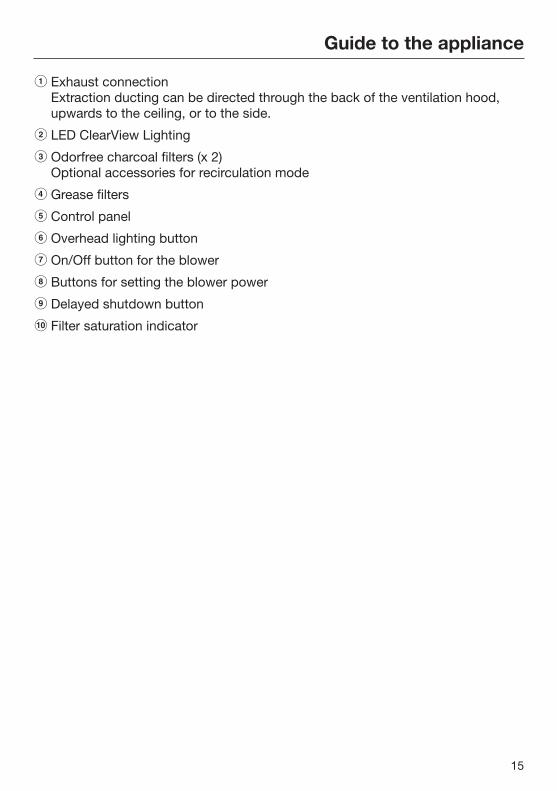
a Exhaust connectionExtraction ducting can be directed through the back of the ventilation hood,upwards to the ceiling, or to the side.
b LED ClearView Lighting
c Odorfree charcoal filters (x 2)Optional accessories for recirculation mode
d Grease filters
e Control panel
f Overhead lighting button
g On/Off button for the blower
h Buttons for setting the blower power
i Delayed shutdown button
j Filter saturation indicator

Description of functions
16
The following functions are available onyour ventilation hood, depending on themodel:
Vented mode
The air is drawn in and cleaned by thegrease filters and directed outside.
Recirculation modeRecirculation mode hoods require arecirculation kit and OdorFree CharcoalFilters (available as optionalaccessories), see "Technical Data" formore information.
The air is drawn in and cleaned first bythe grease filters and then by thecharcoal filters. The clean air is thenrecirculated back into the kitchen.

Description of functions
17
Con@ctivity 2.0 functionAutomatic control
This hood features a communicationfunction which enables the automaticcontrol of the hood based on theoperational status of a Miele inductioncooktop.
To enable the communication function,the cooktop must be equipped with thecorresponding Con@ctivity 2.0 stick .
Please refer to the installationinstructions for the Con@ctivity 2.0stick to determine whether connectionto your cooktop is possible.
There must be radio contact betweenthe cooktop and the hood for you to beable to use the Con@ctivity 2.0 function(see "Activating Con@ctivity 2.0").
The cooktop transmits informationabout its operational status to the hoodusing a radio signal.
– When a burner is turned on, thecooktop lighting on the hood turns onautomatically. After a brief delay, theventilation hood fan also comes on.
– During cooking, the hoodautomatically selects the fan levelbased on the number of burners inoperation and their power levels.
– Once you have turned off thecooktop, the fan and the lighting willturn off automatically after apredetermined delay.
Detailed information about this functioncan be found under "Operation."

Operation (Automatic mode)
18
When Con@ctivity 2.0 is active, thehood always operates in Automaticmode (see "Activating [email protected]").
See "Cooking without Con@ctivity 2.0"for information on manually operatingthe hood.
Cooking with Con@ctivity 2.0(Automatic mode) Turn on a burner to the desired power
setting.
Overhead cooktop lighting.
After a few seconds, the fan will comeon, briefly operating at power level 2before immediately switching to level 1.
The hood selects the fan levelautomatically during cooking.
This level is determined by the totaloutput of the cooktop, i.e. the numberof burners in operation and the powersettings selected.
If you select a higher power settingon the cooktop or switch on multipleburners, the hood will switch to ahigher fan level.
If you select a lower power setting onthe cooktop or turn off a burner, thehood will accordingly switch to alower fan level.
Examples for fan levels 1 to 4
Reaction timeChanging the power setting on thecooktop does not lead to an immediateincrease or decrease in cooking vapors.For this reason, the hood reacts with aslight delay.
Delays can also result from the fact thatthe cooktop transmits the information tothe hood in intervals.
The reaction time can vary from a fewseconds to a couple of minutes.
Operation (Automatic mode)
19
Cooking process If, for example, you switch on a
burner at the highest power setting toheat cookware in preparation forsearing and then reduce the powerlevel after approx. 60 to 90 seconds,a cooking process is recognized.
The hood turns on automatically and,after the cooktop power level has beenreduced, switches back to fan level 3,where it remains for approx. 5 minutes.
After this, the fan level is once againdetermined by the Con@ctivity function.
You can also manually select adifferent fan level before then.
Deactivation Turn off all burners.
Over the next few minutes, theventilation hood fan setting willdecrease one level at a time until thehood eventually turns off.
This helps to neutralize any lingeringvapors and odors in the air.
– From the intensive setting, the fanimmediately switches to level 3.
– If the fan is operating at level 3, it willswitch to level 2 after approx. 1minute.
– From level 2, the fan switches to level1 after 2 minutes.
– After 2 minutes at level 1, the fanautomatically turns off.
– After another 30 seconds, theoverhead cooktop lighting turns off.
The cooking process is now finished.
Operation (Automatic mode)
20
Temporarily exiting AutomaticmodeTo temporarily exit the Automatic modewhen cooking:
Manually select a different fan level,or
Manually turn the hood off, or
Activate the Delayed shut downfunction on the ventilation hood.The fan turns off after the delay timeselected, and the lighting will remainon.
The ventilation hood functions can nowbe operated manually (see "Cookingwithout Con@ctivity 2.0").
Resuming Automatic modeThe ventilation hood resumesAutomatic mode:
If the ventilation hood has not beenused for a period of approx. 5minutes after the manual selection ofa fan level, or
If the manually selected fan levelonce again matches the automaticsetting, or
If the ventilation hood fan and thecooktop have been turned off for atleast 30 seconds.Automatic mode will resume the nexttime the cooktop is turned on.
If you wish to manually operate theventilation hood for a completecooking process, turn on theventilation hood fan before turningon the cooktop.If the ventilation hood and thecooktop have been turned off for atleast 30 seconds after you havefinished cooking, Automatic modewill resume the next time the cooktopis turned on.

Operation (Manual mode)
21
Cooking without [email protected] (Manual mode)The hood can be operated manually if:
– The Con@ctivity 2.0 function is notactivated.
– You have temporarily deactivated theCon@ctivity 2.0 function (see"Temporarily exiting Automaticmode").
Turning on the blower Press the On/Off button .
The blower turns on at level 2. The symbol and 2 will light up in the blowerlevel display.
Selecting the power levelPower levels 1 to 3 can be used for lightto heavy cooking vapors and odors.
For strong vapors and odors that aretemporarily produced when cooking,e.g., during searing, select the Bbooster level.
Press the "" button for a lowerpower level or the "" button toselect a higher level.
Reducing power of the booster level
If power management is activated(default setting), the fan automaticallyswitches back to level 3 after 5 minutes.
Selecting the Delayed shutdown timeIt is a good idea to let the fan run for afew more minutes after cooking in orderto neutralize any lingering vapors andodors in the air.With the Delayed shut down function, itis possible to have the fan automaticallyshut off after a predetermined period oftime.
After you have finished cooking,press the Delayed shut down button5 15
– Once: fan turns off after 5 minutes (5lights up).
– Twice: fan turns off after 15 minutes(15 lights up).
– If you press the Delayed shut downbutton 515 again, the fan remainsturned on (515 goes out).
Turning off the blower Press the On/Off button to turn the
blower off.
The symbol will go out.
Turning the overhead lightingon/offThe overhead lighting can be turned onand off separately from the fan.
To do so, press the button.
The symbol is lit when the overheadlighting is turned on.

Operation (Manual mode)
22
Power managementThe ventilation hood features a powermanagement system to help saveenergy. The blower power level isreduced and the lighting is turned offautomatically.
– If the booster level is selected, theblower automatically switches tolevel 3 after 5 minutes.
– If the blower is set to level 3, 2 or 1, itswitches back one blower settingafter 2 hours and then in 30-minuteintervals until the blower eventuallyswitches off.
– If the overhead lighting is on, it willswitch off automatically after 12hours.
Turning power management on/off
You can deactivate the powermanagement.This can result in increased energyconsumption.
Turn off the blower and the lighting.
Press and hold the delayed shutdownbutton 5 15 for approx. 10 secondsuntil 1 appears in the blower leveldisplay.
Then, press the following buttons insuccession:
– The lighting button ,
– Followed by the "" button and then
– The lighting button again.
If power management is turned on, the1 and B indicators will be continuouslylit.If it is turned off, 1 and B will flash.
Press the "" button to turn powermanagement off.
The 1 and B indicators flash.
To turn it on, press the "" button.
The 1 and B indicators are constantlylit.
Confirm the setting by pressing thedelayed shutdown button 5 15.
All the indicator lights go out.
If the new setting is not confirmedwithin 4 minutes, the hood reverts tothe previous setting.

Operation (Automatic and Manual modes)
23
Filter saturation indicatorThe number of hours the hood hasbeen in operation is stored in appliancememory.
The filter saturation indicators showwhen the filters need to be cleaned orchanged by lighting up the grease filtersymbol or OdorFree Charcoal Filtersymbol . Additional information oncleaning and changing the filters andresetting the filter saturation counterscan be found under "Cleaning andcare."
Adjusting the filter saturationindicator for the grease filter
You can set the filter saturationindicator to suit your cooking habits.
The factory default setting is a cleaninginterval of 30 hours.
– Select a shorter interval of 20 hours ifyou fry food regularly.
– We also recommend a shortercleaning interval if you only cookoccasionally. This will prevent greasebuild-up from hardening and makingcleaning more difficult.
– Select a longer cleaning interval of 40or 50 hours if you use very little fatwhen cooking.
Press the On/Off button to turn theblower off.
Press the delayed shutdown button515 and the filter saturation button at the same time.
The grease filter symbol on the filtersaturation button and one of the blowerpower level indicators will flash.
The indicators 1 to B show the currenttime setting:
Indicator 1 .............................. 20 hours
Indicator 2 .............................. 30 hours
Indicator 3 .............................. 40 hours
Indicator B ............................... 50 hours
Press the "" symbol for a shorteroperating time, or the "" symbol toselect a longer operating time.
Confirm the selection by pressing thefilter saturation indicator .
All the indicator lights will go out.
If the new setting is not confirmedwithin 4 minutes, the hood reverts tothe previous setting.

Operation (Automatic and Manual modes)
24
Activating/changing the charcoalfilter saturation indicator
The charcoal filter is required for therecirculation mode.
The filter saturation indicator for thecharcoal filter must be activated onceand should be set to match yourcooking habits.
Press the On/Off button to turn theblower off.
Press the "" symbol and the filtersaturation indicator at the sametime.
The charcoal filter symbol and one ofthe blower power level indicators willflash.
The indicators 1 to B show the currenttime setting:
Indicator 1 ............................ 120 hours
Indicator 2 ............................ 180 hours
Indicator 3 ............................ 240 hours
Indicator B .......................... deactivated
Press the "" symbol for a shorteroperating time, or the "" symbol toselect a longer operating time.
Confirm the selection by pressing thefilter saturation indicator .
All the indicator lights go out.
If the new setting is not confirmedwithin 4 minutes, the hood reverts tothe previous setting.
Checking the filter saturationindicator
Before the set operating time has runout, you can check what percentage ofthe time has elapsed.
Press the On/Off button to turn theblower on.
Press and hold the filter saturationindicator :
– Once, to check the grease filteroperating time. The grease filtersymbol lights up.
– Twice, to check the charcoal filtersaturation. The charcoal filter symbol lights up.
One or more of the blower power levelindicators will flash simultaneously.
The number of flashing indicatorsshows the elapsed operating time as apercentage.
Indicator 1 .................................... 25%
Indicators 1 and 2 ......................... 50%
Indicators 1 to 3 ........................... 75%
Indicators 1 to B ......................... 100%
The elapsed operating time remainsstored in the memory when theventilation hood is turned off or in theevent of an interruption to the powersupply.

Energy-saving tips
25
This hood operates in a very efficientand energy-saving manner. Thefollowing will help you to save evenmore energy when using it:
– Ensure that there is sufficientventilation in the kitchen whencooking. If there is insufficient air flowduring vented mode, the hoodcannot operate efficiently, causingincreased operating noise levels.
– Always cook with the lowest possiblesetting. This produces fewer cookingvapors so that you can use a lowerhood power level and thereforebenefit from reduced energyconsumption.
– Check the power level selected onthe hood. A lower power level isgenerally sufficient for the majority ofcooking. Only use the booster levelwhen necessary.
– When a large volume of cookingvapors are being produced, switch toa high power level in good time. Thisis more efficient than operating thehood for longer to try to capturecooking vapors that have alreadybeen distributed throughout thekitchen.
– Make sure that you switch off thehood after use.
– Clean or change the filters at regularintervals. Heavily soiled filters reduceperformance, increase the risk of fireand are unhygienic.
Cleaning and care
26
WARNING: TO REDUCE THE RISKOF FIRE, ELECTRIC SHOCK, ORINJURY TO PERSONS, OBSERVETHE FOLLOWING:
Before cleaning or servicing thehood, disconnect it from the powersupply, see "IMPORTANT SAFETYINSTRUCTIONS".
Stainless steel housing
General information
The surfaces and control buttons aresusceptible to scratching andchipping.Observe the following cleaninginstructions.
Clean all surfaces and control buttonsusing warm water and liquid dishsoap. Apply with a sponge cloth.
Make sure that no water gets into theinterior of the hood.Only use a damp cloth to clean thehood, especially in the control panelarea.
After cleaning, dry the surfaces with asoft cloth.
Avoid the following:
– Cleaners containing soda, acid orchloride, or cleaners containingsolvents
– Abrasive sponges, e.g. pot scourersor sponges which have beenpreviously used with abrasivecleaning agents.
Grease filtersThe reusable metal grease filters in theappliance remove the solid particlescontained in kitchen vapors (fat, dust,etc.), thereby preventing the ventilationhood from becoming dirty.
A dirty filter is a fire hazard!
Cleaning intervals
Over longer periods of time, fat buildupon the grease filter hardens and makescleaning more difficult. Therefore, werecommend cleaning the grease filtersonce every 3-4 weeks.
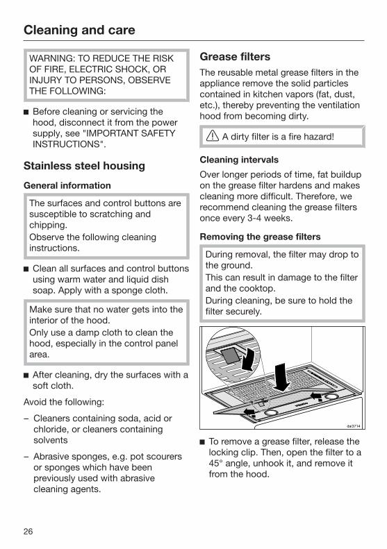
Removing the grease filters
During removal, the filter may drop tothe ground.This can result in damage to the filterand the cooktop.During cleaning, be sure to hold thefilter securely.
To remove a grease filter, release thelocking clip. Then, open the filter to a45° angle, unhook it, and remove itfrom the hood.

Cleaning and care
27
Cleaning the grease filters by hand
Clean the filters with a soft nylonbrush in a mild solution of hot waterand dish soap. Do not use undiluteddish soap.
Unsuitable cleaning agents
Unsuitable cleaners can cause damageto the filter surfaces if used regularly.Do not use any of the following:
– Lime removers
– Abrasive powders or abrasive liquids
– Aggressive all-purpose cleaners anddegreaser sprays
– Oven sprays
Cleaning the grease filters in thedishwasher
Place the filters as upright as possiblein the lower basket. Ensure that thespray arm is not obstructed.
Use a common dishwashingdetergent.
Select a program with a washtemperature between 120°F (50°C)and 150°F (65°C). In a Mieledishwasher use the "Normal"program.
Depending on the detergent used,cleaning the filters in a dishwashermay cause the inside filter surfaces tobecome discolored. However, this willnot affect the functioning of the filtersin any way.
After cleaning
After cleaning, leave the filters on anabsorbent surface to dry.
When removing the filters forcleaning, also clean off anyaccessible oil or fat buildup from thehousing. Doing so will prevent a firehazard.

Cleaning and care
28
Resetting the filter saturation counterfor the grease filters
Once cleaning is complete, the filtersaturation counter must be reset.
While the fan is turned on, press thefilter saturation indicator forapprox. 3 seconds until 1 is the onlyindicator flashing.
The grease filter symbol goes out.
When cleaning the grease filters beforethe full operating time has elapsed:
Press the filter saturation indicator for approx. 6 seconds until 1 isthe only indicator flashing.
Reinstall the grease filters. Wheninserting the filters, make sure thatthe locking clip is facing down.
If the filters have been installedincorrectly, you can insert a smallscrewdriver into the slit to disengagethe locking clip.
OdorFree Charcoal FilterWith recirculation mode, two charcoalfilters must be fitted in addition to thegrease filters. These are designed toabsorb cooking odors. They are fitted into the canopy abovethe grease filters.
Charcoal filters are available from yourMiele dealer or from Miele. See"Technical data" for the type andreference number.
Installing/replacing the charcoalfilters
Before installing or replacing thecharcoal filters, you must first removethe grease filters (see previoussection for instructions).
Take the charcoal filters out of theirpackaging.
Press the filters into the frame.
Reinstall the grease filters.
When installing the filter for the firsttime, activate the filter saturationcounter (see "Operation").

Cleaning and care
29
When to change the OdorFreeCharcoal Filter
Always replace the OdorFreeCharcoal Filters whenever they nolonger absorb kitchen odorseffectively.The charcoal filters should bereplaced at least once every 6months.
The charcoal filter saturation indicator will light up to remind you to changethe charcoal filter regularly.
The charcoal filter saturation counterrequires one-time activation beforeuse (see the "Operation" chapter).
Resetting the filter saturationindicator for the charcoal filter
If the filter saturation counter isactivated, it must be reset each time thefilter is changed.
To do this, press the filter saturationindicator twice with the fanturned on and hold it for approx. 3seconds until 1 is the only indicatorflashing. The charcoal filter symbol will go out.
If you replace the charcoal filters beforethe full time interval elapses:
Press the filter saturation indicator twice and hold it for approx. 6seconds until 1 is the only indicatorflashing.
Disposing of the OdorFree charcoalfilter
Used charcoal filters can be disposedof with normal household waste.

Cleaning and care
30
Changing a light bulb
Only use the specified light bulbs.Other bulbs, for example halogenbulbs, may become damaged due tothe high generation of heat.
The light bulbs should be replaced withthe following:
Bulb type .............................. LED, GU10Power ............................................... 3W
Light bulbs are available from Miele orspecialist dealers.
Turn off the blower and the lighting.
The light bulbs can get very hotwhen in use.Allow the bulbs to cool down for afew minutes before changing them.
Disconnect the hood from theelectrical supply before replacing thelight bulbs (see "IMPORTANTSAFETY INSTRUCTIONS").
Insert the lever supplied into the gapbetween the bulb and the bulbholder..
The bulb will then drop downwards.
Grip the light bulb, turn itcounterclockwise and take it out.
Screw the new bulb into the socketand push it upwards. Please followthe manufacturer's safetyinstructions.

Installation
31
Before installation
Before installing the appliance,read all of the information containedin this chapter and also in the"IMPORTANT SAFETYINSTRUCTIONS" section.
Installation InstructionsPlease refer to the accompanyinginstallation sheet for instructions onhow to install the appliance.
The ventilation hood is intended forinstallation in wall cabinets, ventilationhousing units, vent flues or abovekitchen islands.
Before installing, check to make surethat the top of the appliance will beaccessible once it is installed.
If this is not the case, install the exhaustducting and prepare the mainsconnection before installation.

Installation
32
Installation parts

Installation
33
a 1 collar for exhaust ducting 6" /150 mm.
b 1 reducing collar for exhaustducting 5" / 125 mm.
c Conversion kit for recirculationmode (the conversion kit is notsupplied. It must be orderedseparately as an optional accessory- see "Technical data"). The kitcontains an exhaust grille andflexible aluminum hose with hoseclips.
6 screws, ¹/₈" x ⁵/₈" (3.5 x 16 mm)screws for securing the range hood.
The provided screws are intended forthe attachment of the hood to a solidwooden cabinet floor with aminimum thickness of ⁵/₈" (16 mm).Ensure the floor can permanentlysupport the applied load.
Keep the following in a safe place:
Montage
Installation
Montaje
M
ontaggio
Montering
Montagem
A
sennus
Installation plan
1 leverfor replacing the lamps.

Installation
34
Appliance dimensions
The drawing is not to scale.

Installation
35
a The ducting can also be connected at the back.
Distance between cooktop and ventilation hood (S)
Provided a larger distance is not given by the manufacturer of the cooktop,follow the minimum safety distances between a cooktop and the bottom of thehood.Please also observe the information contained in the "IMPORTANT SAFETYINSTRUCTIONS" section.
Minimum distance S
Cooking appliance Mieleappliance
Non-Mieleappliance
Electric Cooktops 24" (610 mm)
Electric Barbeques and Fryers 26" (660 mm)
Multiburner Gas Cooktops ≤ 43,000 BTU/hr (12.6 kW), no burner > 15,000 BTU/hr (4.5 kW).
26" (660 mm) 30" (760 mm)
Multiburner Gas Cooktops ≤ 73,800 BTU/hr (21.6 kW), no burner > 16,500 BTU/hr (4.8 kW)
30" (760 mm)
Multiburner Gas Cooktops > 73,800 BTU/hr (21.6 kW), or one of the burners > 16,500 BTU/hr (4.8 kW)
Not possible
Single Burner Gas Cooktops ≤ 20,500 BTU/hr (6 kW)
26" (660 mm) 30" (760 mm)
Single Burner Gas Cooktops > 20,500 BTU/hr (6 kW)≤ 27,600 BTU/hr (8.1 kW)
30" (760 mm)
Single Burner Gas Cooktops > 27,600 BTU/hr (8.1 kW)
Not possible

Installation
36
Installation recommendations– To achieve optimum vapor extraction,
the hood must be centered over thecooktop, not to the side.
– The mounting area must be easilyaccessible. The ventilation hoodshould be easy to reach anddisassemble in case a service call isnecessary. This should be taken intoconsideration when planning theposition of cabinetry, shelves,ceilings or decorative elements in thevicinity of the ventilation hood.

Air venting
37
WARNING: Danger of toxic fumes.Gas cooking appliances releasecarbon monoxide that can beharmful or fatal if inhaled.To reduce the risk of fire and toproperly exhaust air, the exhaustgases extracted by the hood shouldbe vented outside of the buildingonly.Do not vent exhaust air into spaceswithin walls or ceilings or in attics,crawl spaces or garages.To reduce the risk of fire, only usemetal ductwork.Please read and follow the"IMPORTANT SAFETYINSTRUCTIONS" to reduce the riskof personal injury. Follow all localbuilding codes when installing thehood.
Only use smooth pipes or flexibleduct hoses made from non-combustible materials for exhaustductwork.
To achieve the greatest possible airextraction with the lowest noise levels,please note the following:
– The diameter of the exhaust ductshould not be less than 6" (150 mm).
– If flat exhaust ducts are used, thecross section should not be smallerthan that of the exhaust connector.
– The exhaust duct should be as shortand straight as possible.
– If elbows are needed, make sure theyhave a large radius.
– The exhaust duct itself must not bekinked or compressed.
– Make sure that all connections aresecure and airtight.
Remember that any constriction ofthe airflow will reduce extractionperformance and increase operatingnoise.
If the exhaust duct is to be routedthrough an outside wall, werecommend installing a telescopicwall vent or a rooftop vent (availableas an optional accessory).
If the exhaust air is conveyed into anexhaust air chimney, the inletconnector must face the flowdirection.
When installing the exhaust ducthorizontally, a minimum slope of ¹/₈ inchper foot must be maintained to preventcondensate from flowing into theventilation hood.
If the exhaust duct is to be routedthrough cool rooms, ceilings, etc., thetemperatures in these different areasmay differ greatly. Therefore watercondensation must be consideredand the exhaust duct will need to beinsulated.

Air venting
38
Reducing Collar(optional accessory)
If you would like to reduce theenvironmental impact of your ventilationsystem by limiting the CFM output theReducing Collar can be installed. Itreduces the air flow to less than400 CFM. Check local building codesfor max. CFM requirements.
Push the Reducing Collar on theexhaust port of the blower.
Push the exhaust hose over it.
Secure both with a hose clamp.
Electrical connection
39
WARNING: TO REDUCE THE RISKOF FIRE, ELECTRIC SHOCK, ORINJURY TO PERSONS, OBSERVETHE FOLLOWING:All electrical work should beperformed by a qualified electricianin strict accordance with nationalregulations (for USA: ANSI-NFPA 70)and local safety regulations.Installation, repairs and other workby unqualified persons could bedangerous.Ensure that power to the appliance isOFF while installation or repair workis performed.Verify that the voltage, load andcircuit rating information found onthe data plate (located behind thebaffle filters), match the householdelectrical supply before installing thehood.Use only with ventilation hood cord-connection kits that have beeninvestigated and found acceptablefor use with this model hood.If there is any question concerningthe electrical connection of thisappliance to your power supply,please consult a licensed electricianor call Miele’s Technical ServiceDepartment.
WARNING: THIS APPLIANCE MUSTBE GROUNDED
Grounding Instructions
WARNING - Improper grounding canresult in a risk of electric shock.
This appliance must be grounded. Inthe event of an electrical short circuit,grounding reduces the risk of electricshock by providing a path of leastresistance. This appliance is equippedwith a cord having a grounding wirewith a grounding plug.
If there is any doubt, have the electricalsystem of the house checked by aqualified electrician.
Do not use an extension cord. If thepower supply cord is too short, have aqualified electrician install an outlet nearthe appliance.
The plug must be plugged into anoutlet that is properly installed andgrounded.
WARNING - Grounding instructions(Canada)The grounding-type attachment plugshall be connected to a grounding-type receptacle installed inaccordance with CSA C22.1-12,Canadian Electrical Code, Part I.

Activating Con@ctivity 2.0
40
Installation of the [email protected] stickIn order for you to be able to use theCon@ctivity 2.0 function, the cooktopmust be equipped with a [email protected] stick.
See the relevant installationinstructions of the Con@ctivity 2.0stick.
Activating the Con@ctivity 2.0functionTo use the Con@ctivity 2.0 function, theradio link between the cooktop and theventilation hood must be activated.
Both appliances must be installed andoperational.
Wireless connection must be activatedon the ventilation hood and the cooktopat the same time. Activation on theventilation hood is described below. Activation on the cooktop is describedin the relevant operating and installationinstructions. Please refer to theoperating instructions before starting.Activate the ventilation hood first, thenthe cooktop.
Activating the ventilation hood
The cooktop and ventilation hoodmust be turned off.
Press and hold the delayed shutdownbutton 515 for approx. 10 secondsuntil the 1 indicator appears in the fanlevel display.
Then, press the following buttons inorder:
– The button
– Followed by the button
– And then the lighting button .
The hood is in log on / log off mode.
If the wireless connection is activated, 2and 3 will light up at the same time. If there is no wireless connection, 2 and3 will flash constantly (Con@ctivity 2.0is already activated or a remote controlis logged on).
To activate Con@ctivity 2.0, press the"" button.
The search for a wireless connectionwill start.
As this is happening, activate thecooktop.

Activating Con@ctivity 2.0
41
Activating the cooktop
While the ventilation hood issearching for a wireless connection,start activation on the cooktop.More information can be found in theoperating instructions for thecooktop.
When the cooktop registers thatconnection has been established,confirm activation on the ventilationhood with the delayed shut-downbutton 515. All indicators will goout.
Confirm activation on the cooktop.
The Con@ctivity 2.0 function is nowready for use.
If you do not confirm within 4 minutes,activation will be canceled.
You only need to carry out theactivation procedure once. If theappliances are disconnected from theelectricity supply, for example during aloss of power, they will still remainactivated.
Activation failed
If a wireless connection cannot beestablished despite activation of theCon@ctivity function on theventilation hood and cooktop, thefunction must first be deactivated andthen reactivated on both appliances.
Deactivating Con@ctivity 2.0 Deactivation on the ventilation hood
is carried out in the same way asactivation, by selecting instead of.
To deactivate the burner, please referto the corresponding operatinginstructions.
Please keep in mind that disabling theconnection will also disable anyremote control function being used.The remote control must then bereactivated.

Service and warranty
42
For faults that you cannot resolve onyour own, please contact your Mieledealer or Miele Technical Service.
The telephone number for Miele is listedat the back of these instructions.
When contacting Miele, please state themodel and serial number of yourventilation hood.These can be found on the data plate.
Location of the data plateThe data plate is visible once you haveremoved the grease filters.
WarrantyFor further information, please refer toyour warranty booklet.
MieleCare
This service is available in USA only.
MieleCare, our Extended ServiceContract program, gives you theassurance of knowing that yourappliance investment is covered by5 years of worry free ownership.MieleCare is the only Extended ServiceContract in the industry that guaranteesrepairs by a Miele Authorized ServiceProvider using genuine Miele parts.Only genuine Miele parts installed byfactory trained professionals canguarantee the safety, reliability, andlongevity of your Miele appliance.
Please note that unless expresslyapproved in writing by Miele’s Servicedepartment, Extended ServiceContracts offered by other providers forMiele products will not be recognizedby Miele. Our goal is to preventunauthorized (and untrained) servicepersonnel from working on your Mieleproducts, possibly doing furtherdamage to them, you and/or yourhome.
To learn more about MieleCareExtended Service Contracts, pleasecontact your appliance dealer or visit usonline at:www.mieleusa.com

Technical data
43
Blower motor 350 W
LED ClearView Lighting
DA 2580 2 x 3 W
DA 2510 4 x 3 W
Total connected load
DA 2580 356 W
DA 2510 362 W
Voltage, frequency 120 V AC, 60 Hz
Fuse rating 15 A
Power cord length 2.5 ft (0.75 m)
Weight
DA 2580 26.6 lbs (12.1 kg)
DA 2510 31.5 lbs (14.3 kg)
Optional accessories for recirculation mode
DUU 150 or DUU 151 conversion kit and charcoal filter set DKF 15-900. The setcontains 2 charcoal filters.


9 Independence WayPrinceton, NJ 08540Phone:Fax:www.mieleusa.com
U.S.A.Miele, Inc.
National Headquarters
Please have the model and serial numberof your appliance available whencontacting Technical Service.
CanadaImporterMiele Limited
Headquarters and Miele Centre
800-843-7231609-419-4298
Technical Service & SupportPhone:Fax:[email protected]
161 Four Valley DriveVaughan, ON L4K 4V8www.miele.ca
800-999-1360888-586-8056
Customer Care CentrePhone:
800-565-6435905-532-2272
International HeadquartersMiele & Cie. KGCarl-Miele-Straße 2933332 GüterslohGermany

M.-Nr. 10 561 080 / 02en-US
DA 2580, DA 2510