Embed Size (px)
Citation preview

seepex INC. 511 Speedway Drive Enon, Ohio 45323 Tel +1 (937) 864-71 50 Fax +1 (937) 864-71 57 [email protected] www.seepex.com
Issue: 22.07.2009
Operating and Assembly Instruction Progressive Cavity Pump
Commission No. Type 800000-800001 BN 300-6L
Job# XXX
Read instruct ions before beginning any work!
Always keep instruct ions handy on the worksi te.
24h Helpline: www.seepex.com
Index
1 Safety................................................................................................................................................... 11.1 General Information1.2 Safety and warning notices
1.2.1 Warning notices 1.2.2 Hazard signs1.2.3 Information signs
1.3 Hazards that may arise from the machine1.4 Qualification of personnel1.5 Authorised persons
1.5.1 Tasks and information for the operating company / operator1.5.2 Safety information for maintenance, technical service and assembly work
1.6 Equipment for personal protection1.7 Safety and protective devices1.8 Foreseeable misuse1.9 Normal usage1.10 Warranty
2 Description of the pump.....................................................................................................................52.1 General description2.2 Mode of action and conveying principle of seepex pumps2.3 Construction
3 Technical Data .................................................................................................................................... 63.1 Data sheet ................................................................................................................................73.2 Characteristic line...................................................................................................................103.3 Declaration of conformity / Declaration by the manufacturer..................................................11
4 Transport........................................................................................................................................... 124.1 Safety4.2 Transport
4.2.1 Dimensions and weight4.2.2 Pictographs4.2.3 Jacking points (AP) for lifting gear4.2.4 Unpacking the machine
4.3 Intermediate storage / preserving4.4 Disposal
Index
5 Assembly / Installation.....................................................................................................................145.1 Mounting tools / lifting gear5.2 Required space
5.2.1 Stator construction dimensions5.3 Erection of the complete mounted pump5.4 Energy supply to the seepex pump5.5 Pipe work
5.5.1 Suction and pressure connection5.5.2 Dimensioning of pipe work5.5.3 Residue-free pipe work5.5.4 Tension-free mounting
5.6 Dimsnesional Drawing............................................................................................................16
6 Commissioning / De-Commissioning............................................................................................. 176.1 Commissioning report............................................................................................................ 176.2 Measures before commissioning............................................................................................18
6.2.1 Check pipe work6.2.2 Protective devices on the pump6.2.3 Electrical/hydraulic connections6.2.4 Monitoring the direction of rotation6.2.5 Auxiliary equipment – optional
6.3 Initial commissioning / re-commissioning6.3.1 Avoiding dry running of the pump6.3.2 Pressure on the suction and pressure connection
6.4 De-commissioning6.4.1 Switching the pump off6.4.2 Emptying the pump6.4.3 Dismantling the pump6.4.4 Preserving / placing pump in storage
7 Maintenance...................................................................................................................................... 227.1 Preventative measures
7.1.1 Standstill of the pump7.2 Lubrication
7.2.1 Joint grease7.3 Technical service
8 Faults, causes and repair.................................................................................................................24
9 Pump dismantling / reassembly......................................................................................................269.1 Pump......................................................................................................................................26
9.1.1 Prepare the pump for dismantling9.1.2 Dismantling9.1.3 Reassembly

Index
9.2 Rotating unit – individual parts .............................................................................................. 319.2.1 Dismantling9.2.2 Prepare individual parts for reassembly9.2.3 Reassembly
9.3 Holding band - assembly........................................................................................................359.3.1 Prepare the holding band9.3.2 Check the holding band9.3.3 Assembling the holding band9.3.4 Correct tension for the holding band 9.3.5 Cant the holding band 9.3.6 Shear the holding band 9.3.7 Check the holding band after assembly
9.4 Mechanical seal ..................................................................................................................... 379.4.1 Safety9.4.2 Application conditions and material version9.4.3 Design9.4.4 Commissioning 9.4.5 Monitoring during operation9.4.6 Dismantling of mechanical seal9.4.7 Reassembly of mechanical seal
9.6 Sectional drawing shaft sealing..............................................................................................40
10 Spare parts........................................................................................................................................ 4110.1 Order template for spare parts............................................................................................... 4210.2 Sectional drawing and parts list..............................................................................................45
11 Special tools......................................................................................................................................4811.1 Master copy tools
12 Related documents...........................................................................................................................4912.1 Accessories............................................................................................................................5012.2 Technical Information............................................................................................................. 58
13 Annex.................................................................................................................................................6113.1 Manufacturer’s documents from sub-supplier
13.1.1 gearbox......................................................................................................................6213.1.2 Motor ......................................................................................................................... 73
Subsidiaries
1Ausgabeissue C / 11.10.2005
Dokumentdocument OM.SAF.01e Blatt
sheet 1 (4)
1Safety
1.1 General notes
Always keep the operating and maintenance instructions close by the machine.If problems cannot be solved with reference to the operating and maintenance instructions, please contact the manufacturer.
Observe the following points in addition to these operating and maintenance instructions:• Prohibition, warning and mandatory signs, warning notes on the machine• Relevant laws and ordinances• Statutory provisions on accident prevention• Corresponding harmonised standards and regulations
1.2 Safety and warning notes
Comply with safety and warning notes for safe and efficient use of the product.Signal words for specific dangers and (possible) consequences are explained below. These are supplemented by symbols (pictograms) if necessary.
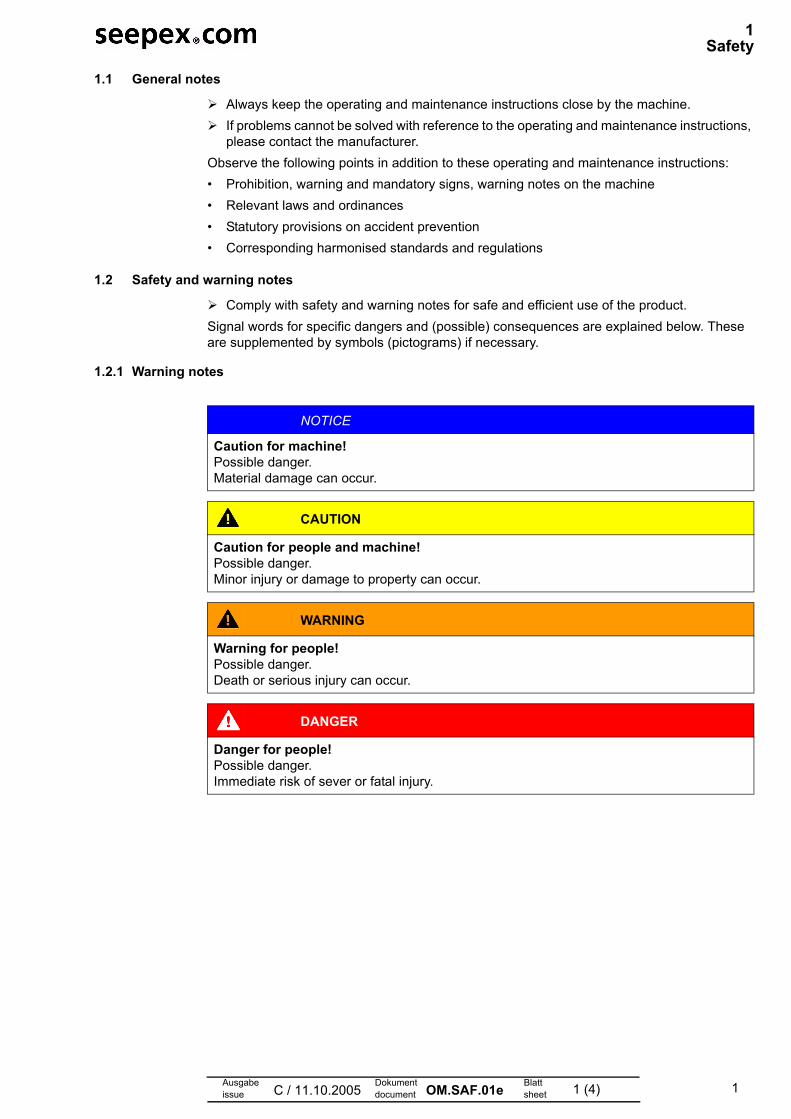
1.2.1 Warning notes
NOTICE
Caution for machine!Possible danger.Material damage can occur.
CAUTION
Caution for people and machine!Possible danger.Minor injury or damage to property can occur.
WARNING
Warning for people!Possible danger.Death or serious injury can occur.
DANGER
Danger for people!Possible danger.Immediate risk of sever or fatal injury.
2
1 Safety
Ausgabeissue C / 11.10.2005
Dokumentdocument OM.SAF.01e Blatt
sheet 2 (4)
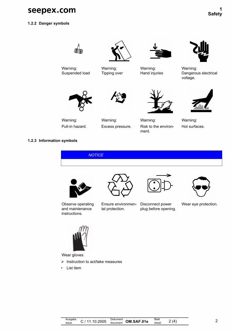
1.2.2 Danger symbols
1.2.3 Information symbols
Instruction to act/take measures• List item
Warning: Suspended load
Warning: Tipping over
Warning: Hand injuries
Warning: Dangerous electrical voltage.
Warning: Pull-in hazard.
Warning: Excess pressure.
Warning: Risk to the environ-ment.
Warning: Hot surfaces.
NOTICE
Observe operating and maintenance instructions.
Ensure environmen-tal protection.
Disconnect power plug before opening.
Wear eye protection.
Wear gloves.
3
1 Safety
Ausgabeissue C / 11.10.2005
Dokumentdocument OM.SAF.01e Blatt
sheet 3 (4)
1.3 Dangers that can be caused by the machine
seepex machines are built in accordance with the state of the art.Nevertheless, there is a residual risk, because the machine works with:• Mechanical movements that pose a danger• Electrical voltages and currentsWe have used design measures and applied safety technology to minimise the risk to the health of people posed by this danger.
1.4 Qualification of the personnel
This handbook is intended for:• Owner• Operators• Setters• Maintenance personnel
1.5 Authorised people
People authorised to undertake operation, set up and maintenance are instructed and trained specialists employed by the owner/manufacturer.
The owner is responsible for:• Personnel training• Compliance with safety regulations• Compliance with operating and maintenance instructionsThe operator must:• Have received instruction• Read and understood the relevant parts of the operating instructions before starting work• Know the safety devices and regulations
1.5.1 Tasks and information for the owner/operators
Regularly check and maintain the machine, replacing all parts in good time which no longer guarantee safe operation.It is essential to comply with the procedure described in the operating instructions for shut-ting down the machine.
• On completion of work, attach all safety and protective devices and make sure they are functioning.
1.5.2 Safety notes for maintenance, inspection and assembly work
Do not work on the machine or system unless it is stationary and depressurised.Switch off the master switch and pull out the power plug before starting work on live com-ponents.Comply with the procedure for shutting down the machine as described in the Shut-down chapter.Decontaminate (de-toxify) machines that are used for pumping media that can be harmful to health.Refer to the Initial start-up chapter before repeated start-up of the machine.
Detailed technical knowledge is essential for performing any work on the machine.
4
1 Safety
Ausgabeissue C / 11.10.2005
Dokumentdocument OM.SAF.01e Blatt
sheet 4 (4)
1.6 Personal protective equipment
Wear personal protective equipment and/or additional equipment for your own safety.Avoid/limit risks by the use of collective technical protective equipment or by organisational measures at work.
1.7 Safety and protective devices
Prior to start-up, bolt seepex machines onto a concrete foundation so as to ensure stability.Starting and stopping devices must be clearly recognisable. Take appropriate measures to avoid defects.
• No protective device is necessary for checking and/or setting the shaft seal.• Hot surfaces are identified with a danger symbol on the machine.
1.8 Foreseeable misuse
Serious personal injury and damage to property can be caused by:• Incorrect use• Incorrect installation or operation of the machine• Impermissible removal of necessary protective equipment
1.9 Designated use
• Only use seepex machines if they are in perfect condition and in compliance with the oper-ating and maintenance instructions.
• Do not start up the machine unless the system in which the machine is installed is in accor-dance with the provisions of the applicable guidelines and statutory regulations.
• Equivalent sustained sound pressure level at workplaces of operating personnel C75 dB (A). Cavitation-free operation of the machine and screwed connection to concrete founda-tion are essential.
• seepex machines are components that are exclusively intended for pumping media in ac-cordance with the technical data (chapter 3.0). Written approval must be obtained from the manufacturer before other media are pumped.
• Refer to the information on the type plate and the operating instructions for technical data (chapter 3.0), and comply with them.
• The operating instructions are assigned to the seepex machine based on the commission number.
Fig. 1-1 Similar illustration
1.10 Statutory guarantee
• Warranty in accordance with our terms and conditions of delivery and order confirmation.• It is a condition of the machine warranty that the machine must correspond to the listed op-
erating instructions in accordance with the type plate/data sheet.• All wearing parts are excluded from the warranty.• These operating instructions are subject to copyright. Reproduction is not permitted and will
be punished. Contravention will be pursued through the courts.
24h Helpline: www.seepex.com
sc
Kommissions-Nr.commission no.
Drehrichtungdirection of rotation
Typtype
seepex GmbHScharnhölzstraße 34446240 BottropTelefon +49.2041.996-0Fax +49.2041.996-400
5Ausgabeissue A / 10.06.2008
Dokumentdocument OM.DES.01e Blatt
sheet 1 (1)
2 Description of the pump
2.1 General description
seepex pumps are members of the group of rotating displacement pumps.• Characteristic features
– Special configuration/arrangement of the rotor and stator pumping elements.– Motion sequence
2.2 Mode of action and pumping principle of the seepex pump
• Seal lines are created by the geometrical configuration/contact between both pumping ele-ments.
• Seal lines provide total separation between the suction and pressure sides.Result:– Increased suction lift capability of the pump– High pressure build-up irrespective of the rotation speed
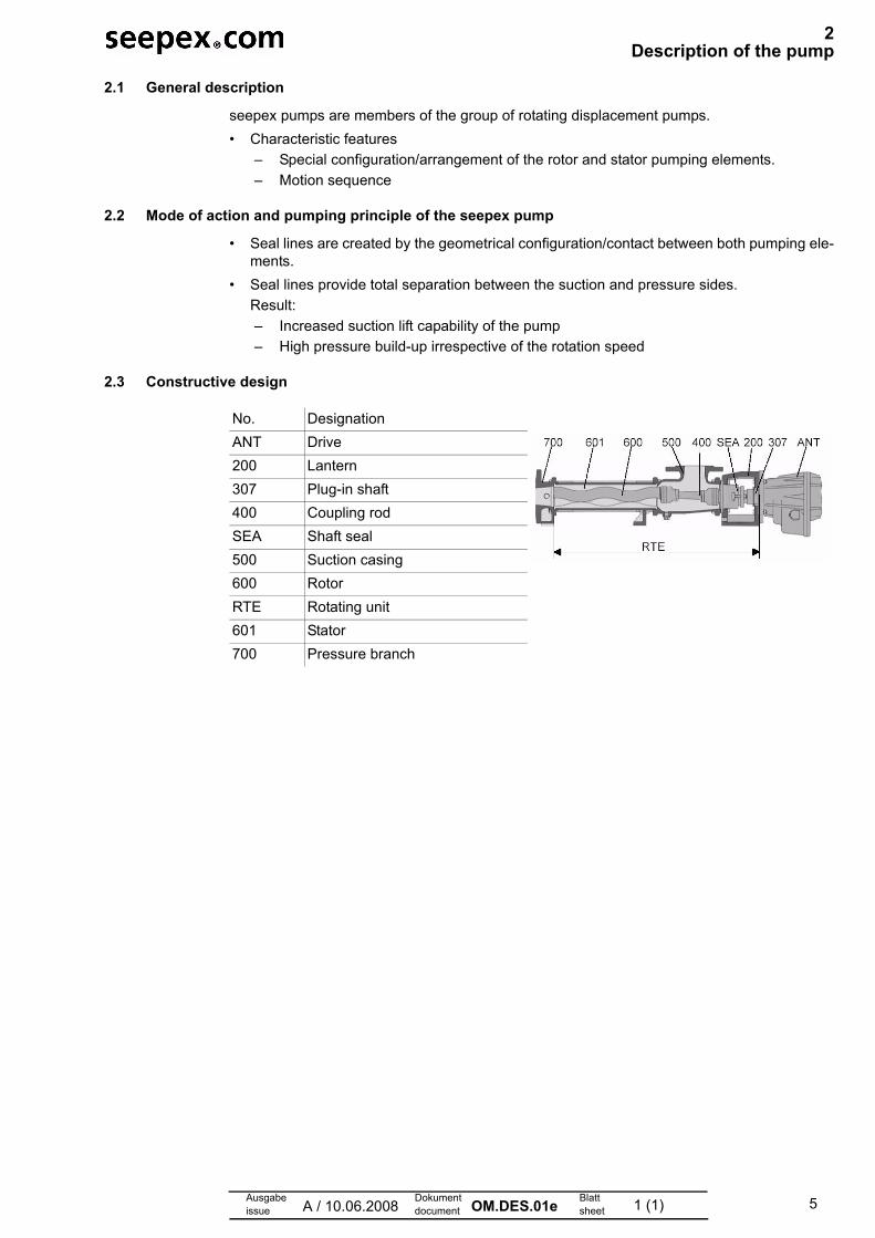
2.3 Constructive design
No. DesignationANT Drive200 Lantern307 Plug-in shaft400 Coupling rodSEA Shaft seal500 Suction casing600 RotorRTE Rotating unit601 Stator700 Pressure branch

6Ausgabeissue A / 01.10.07
Dokumentdocument OM.TED.01e Blatt
sheet 1 (1)
3Technical data
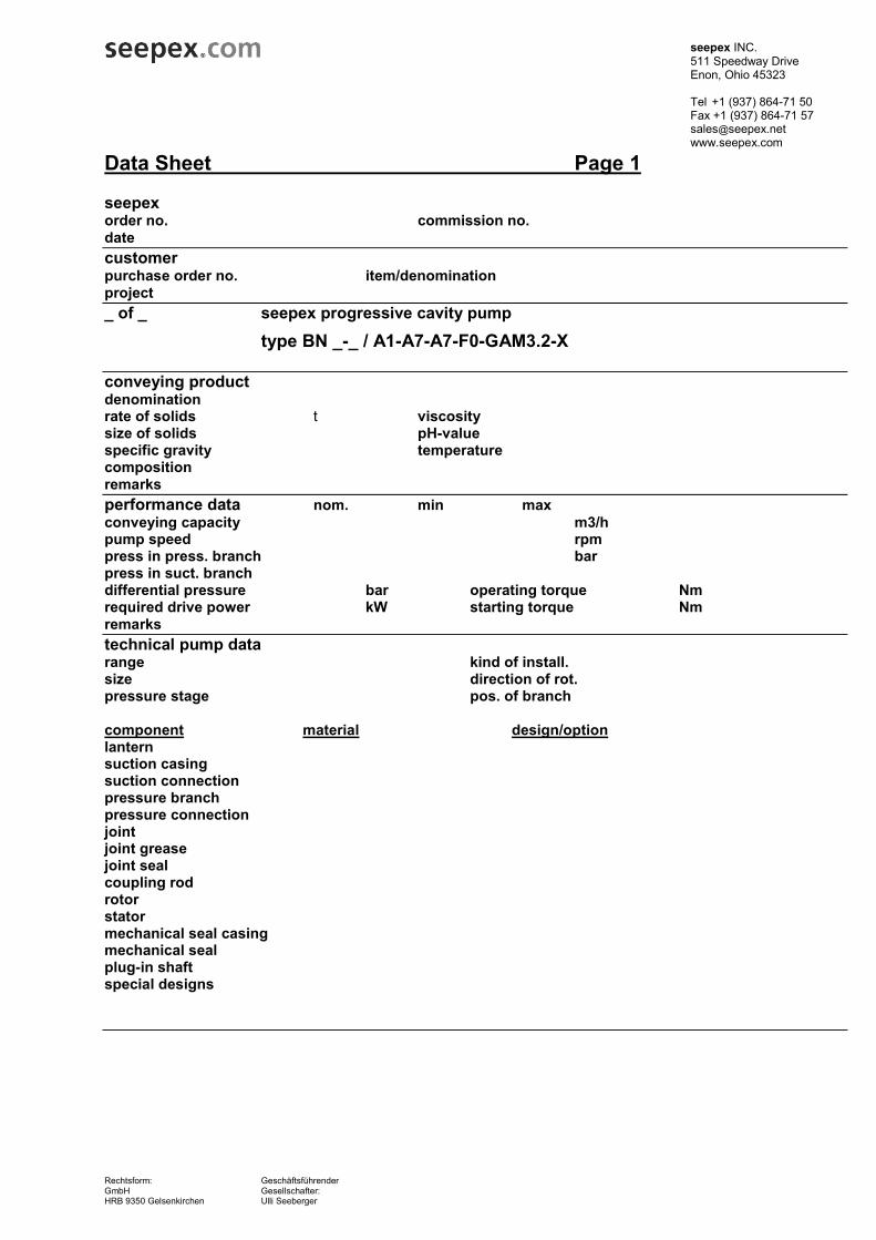
3.1 Data sheet
3.2 Characteristic
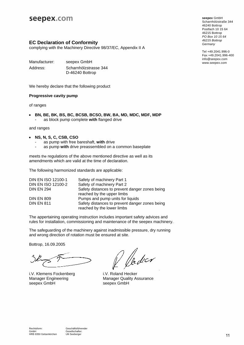
3.3 Declaration of conformity / declaration by the manufacturer
seepex INC. 511 Speedway Drive Enon, Ohio 45323 Tel +1 (937) 864-71 50 Fax +1 (937) 864-71 57 [email protected] www.seepex.com
Rechtsform: Geschäftsführender GmbH Gesellschafter: HRB 9350 Gelsenkirchen Ulli Seeberger
Data Sheet Page 1
seepex order no. commission no. date customer purchase order no. item/denomination project _ of _ seepex progressive cavity pump
type BN _-_ / A1-A7-A7-F0-GAM3.2-X conveying product denomination rate of solids t viscosity size of solids pH-value specific gravity temperature composition remarks performance data nom. min max conveying capacity m3/h pump speed rpm press in press. branch bar press in suct. branch differential pressure bar operating torque Nm required drive power kW starting torque Nm remarks technical pump data range kind of install. size direction of rot. pressure stage pos. of branch
component material design/optionlantern suction casing suction connection pressure branch pressure connection joint joint grease joint seal coupling rod rotor stator mechanical seal casing mechanical seal plug-in shaft special designs

seepex INC. 511 Speedway Drive Enon, Ohio 45323 Tel +1 (937) 864-71 50 Fax +1 (937) 864-71 57 [email protected] www.seepex.com
Rechtsform: Geschäftsführender GmbH Gesellschafter: HRB 9350 Gelsenkirchen Ulli Seeberger
Data Sheet Page 2
general operating data kind of operation site of installation remarks drive type make ratio model mounting position nom./ min - max flange dia output speed output shaft motor speed
frequency type of adjustment speed transmitter speed indication special/accessories
electric motor make model nominal power voltage nominal speed rated frequency mounting position protection starting thermal class
size flange/shaft dia.
provid. of motor fitting of motor baseplate standard material drawing no. surface special/accessories
painting execution color remarks packing packing type marking documentation dimensional drawing no. operating manual sectional drawing no. shaft sealing sect. view QA-documentation
11
EC Declaration of Conformity complying with the Machinery Directive 98/37/EC, Appendix II A Manufacturer: seepex GmbH
seepex GmbH Scharnhölzstraße 344 46240 Bottrop Postfach 10 15 64 46215 Bottrop PO Box 10 15 64 46215 Bottrop Germany Tel +49.2041.996-0 Fax +49.2041.996-400 [email protected] www.seepex.com
Rechtsform: Geschäftsführender GmbH Gesellschafter: HRB 9350 Gelsenkirchen Ulli Seeberger
Address: Scharnhölzstrasse 344 D-46240 Bottrop We hereby declare that the following product Progressive cavity pump of ranges • BN, BE, BK, BS, BC, BCSB, BCSO, BW, BA, MD, MDC, MDF, MDP
- as block pump complete with flanged drive and ranges • NS, N, S, C, CSB, CSO
- as pump with free bareshaft, with drive - as pump with drive preassembled on a common baseplate
meets the regulations of the above mentioned directive as well as its amendments which are valid at the time of declaration. The following harmonized standards are applicable: DIN EN ISO 12100-1 Safety of machinery Part 1 DIN EN ISO 12100-2 Safety of machinery Part 2 DIN EN 294 Safety distances to prevent danger zones being reached by the upper limbs DIN EN 809 Pumps and pump units for liquids DIN EN 811 Safety distances to prevent danger zones being reached by the lower limbs The appertaining operating instruction includes important safety advices and rules for installation, commissioning and maintenance of the seepex machinery. The safeguarding of the machinery against inadmissible pressure, dry running and wrong direction of rotation must be ensured at site. Bottrop, 16.09.2005
i.V. Klemens Fockenberg i.V. Roland Hecker Manager Engineering Manager Quality Assurance seepex GmbH seepex GmbH
EC Declaration by the Manufacturer as defined by the Machinery Directive 98/37/EC, Annex II B
Manufacturer: seepex GmbH
seepex GmbH Scharnhölzstraße 344 46240 Bottrop Postfach 10 15 64 46215 Bottrop PO Box 10 15 64 46215 Bottrop Germany
Tel +49.2041.996-0 Fax +49.2041.996-400 [email protected] www.seepex.com
Rechtsform: Geschäftsführender GmbH Gesellschafter: HRB 9350 Gelsenkirchen Ulli Seeberger
Address: Scharnhölzstrasse 344 D-46240 Bottrop
We hereby declare that the following product Progressive cavity pump of the ranges • BN, BE, BK, BS, BC, BCSB, BCSO, BW, BA, MD, MDC, MDF, MDP
- as block pump without flanged drive as well as • NS, N, S, C, CSB, CSO
- as pump with free bareshaft without drive - as pump preassembled on a baseplate, without drive
meets the regulations of the above mentioned directive as well as its amendments which are valid at the time of declaration. The following harmonized standards are applicable: DIN EN ISO 12100-1 Safety of machinery Part 1 DIN EN ISO 12100-2 Safety of machinery Part 2 DIN EN 294 Safety distances to prevent danger zones being reached by the upper limbs DIN EN 809 Pumps and pump units for liquids DIN EN 811 Safety distances to prevent danger zones being reached by the lower limbs The appertaining operating instruction includes important safety advices and rules for installation, commissioning and maintenance of the seepex machinery. The safeguarding of the machinery against inadmissible pressure, dry running and wrong direction of rotation must be ensured at site.
Bottrop, 03.06.2004
i.V. Klemens Fockenberg i.V. Roland Hecker Manager Engineering Manager Quality Assurance seepex GmbH seepex GmbH
Ausgabeissue A / 29.08.07
Dokumentdocument OM.TRA.01e Blatt
sheet 1 (2)
4Transport
4.1 Safety
4.2 Transport
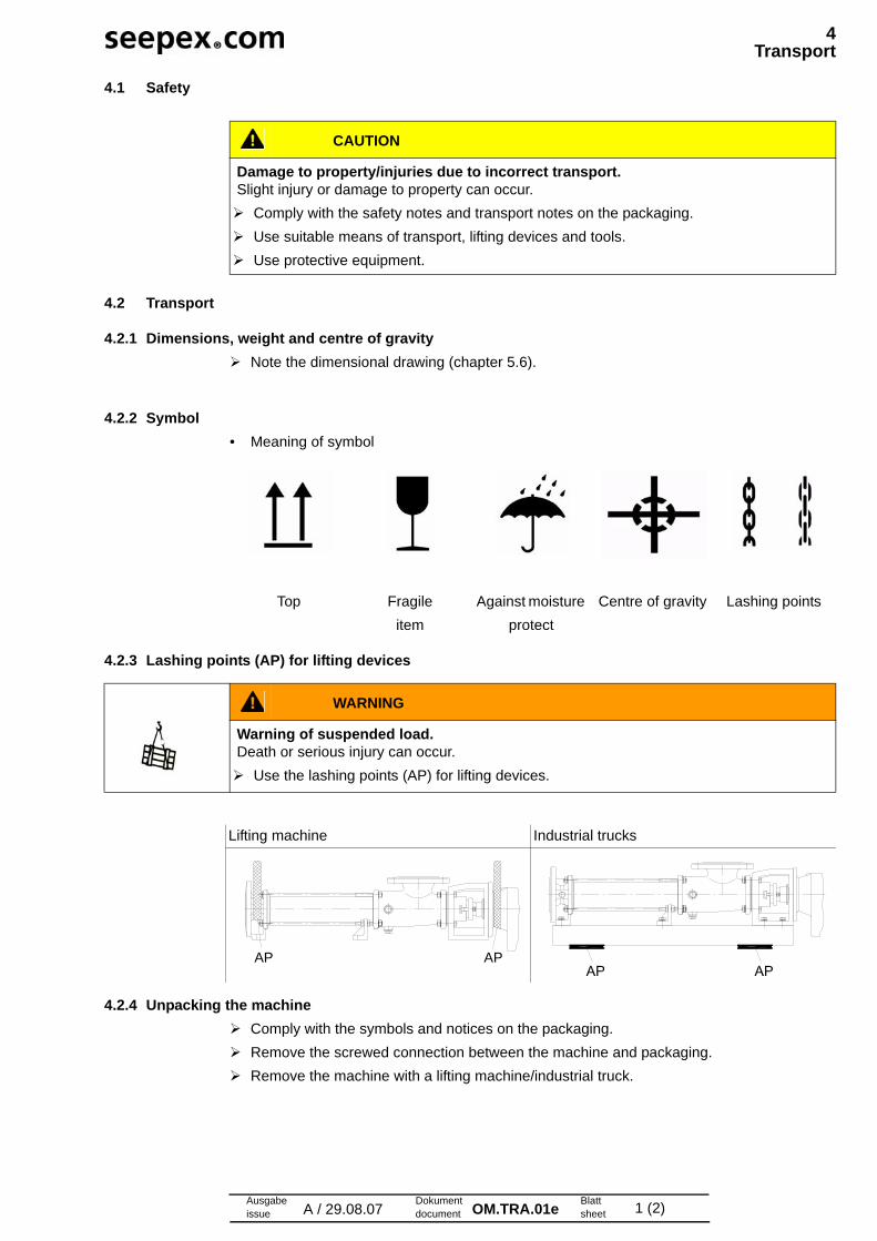
4.2.1 Dimensions, weight and centre of gravity Note the dimensional drawing (chapter 5.6).
4.2.2 Symbol• Meaning of symbol
4.2.3 Lashing points (AP) for lifting devices
4.2.4 Unpacking the machine Comply with the symbols and notices on the packaging. Remove the screwed connection between the machine and packaging. Remove the machine with a lifting machine/industrial truck.
CAUTION
Damage to property/injuries due to incorrect transport.Slight injury or damage to property can occur. Comply with the safety notes and transport notes on the packaging. Use suitable means of transport, lifting devices and tools. Use protective equipment.
Top Fragileitem
Against moisture protect
Centre of gravity Lashing points
WARNING
Warning of suspended load.Death or serious injury can occur. Use the lashing points (AP) for lifting devices.
Lifting machine Industrial trucks
AP AP

4Transport
Ausgabeissue A / 29.08.07
Dokumentdocument OM.TRA.01e Blatt
sheet 2 (2)
4.3 Temporary storage/corrosion protection
• All seepex machines have corrosion protection applied as standard prior to transport.
4.4 Disposal
NOTICE
Damage to property if corrosion protection is missing.Property damage can occur due to corrosion. Temporary storage must be in a dry, enclosed, frost-free room in order to provide protec-
tion against ambient influences. Contact seepex regarding the necessary corrosion protection for temporary storage.
NOTICE
Environmental protection.Material damage can occur. Drain the pumping medium and dispose of it in accordance with the regulations. Dispose of the machine with regard to its composition and existing regulations.

14Ausgabeissue C / 06.07.2007
Dokumentdocument OM.INS.01e Blatt
sheet 1 (2)
5Assembly / Installation
5.1 Mounting tools / lifting gear
5.2 Space requirement
The required space should be determined by considering the following factors:
• Dimensions and weight.
• Requisite transport and lifting equipment.
• Pipe routing – dismantling (dimension for stator replacement).
5.2.1 Dimension for stator replacement (P)
5.3 Assembly of the complete mounted pump
Assemble according to technical data (chapter 3.).
Note dimensional drawing.
Tension-free mounting of the pump Balance unevenness with suitable supports.
• Applies to mounting on foundations/load-bearing elements.
• Total areas of all pump bearing areas are resting on the surface.
Correct position of the drives• All drives are set up ready for operation and mounted.
• Correct displacements of the drive during transport/installation of the pump by adjusting/fix-ing the drive.
CAUTION
Pump falling over.Slight injury or damage to property can occur.
Adhere to the lifting tool’s starting point.
Pay attention to the dimensions, weight and centre of gravity of the pump.
Use suitable mounting tools/lifting gear.
Refer to the dimensional drawing.
CAUTION
Safety protection devices. Slight injury or damage to property may result.
Connect safety protection devices and activate.
15
5Assembly / Installation
Ausgabeissue C / 06.07.2007
Dokumentdocument OM.INS.01e Blatt
sheet 2 (2)
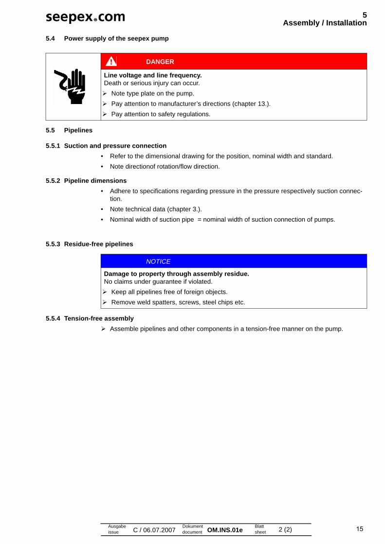
5.4 Power supply of the seepex pump
5.5 Pipelines
5.5.1 Suction and pressure connection• Refer to the dimensional drawing for the position, nominal width and standard.
• Note directionof rotation/flow direction.
5.5.2 Pipeline dimensions• Adhere to specifications regarding pressure in the pressure respectively suction connec-
tion.
• Note technical data (chapter 3.).
• Nominal width of suction pipe = nominal width of suction connection of pumps.
5.5.3 Residue-free pipelines
5.5.4 Tension-free assembly Assemble pipelines and other components in a tension-free manner on the pump.
DANGER
Line voltage and line frequency.Death or serious injury can occur.
Note type plate on the pump.
Pay attention to manufacturer’s directions (chapter 13.).
Pay attention to safety regulations.
NOTICE
Damage to property through assembly residue.No claims under guarantee if violated.
Keep all pipelines free of foreign objects.
Remove weld spatters, screws, steel chips etc.
17Ausgabeissue B / 17.03.2006
Dokumentdocument OM.COM.05e Blatt
sheet 1 (1)
6Commissioning / De-commissioning
Master Copy
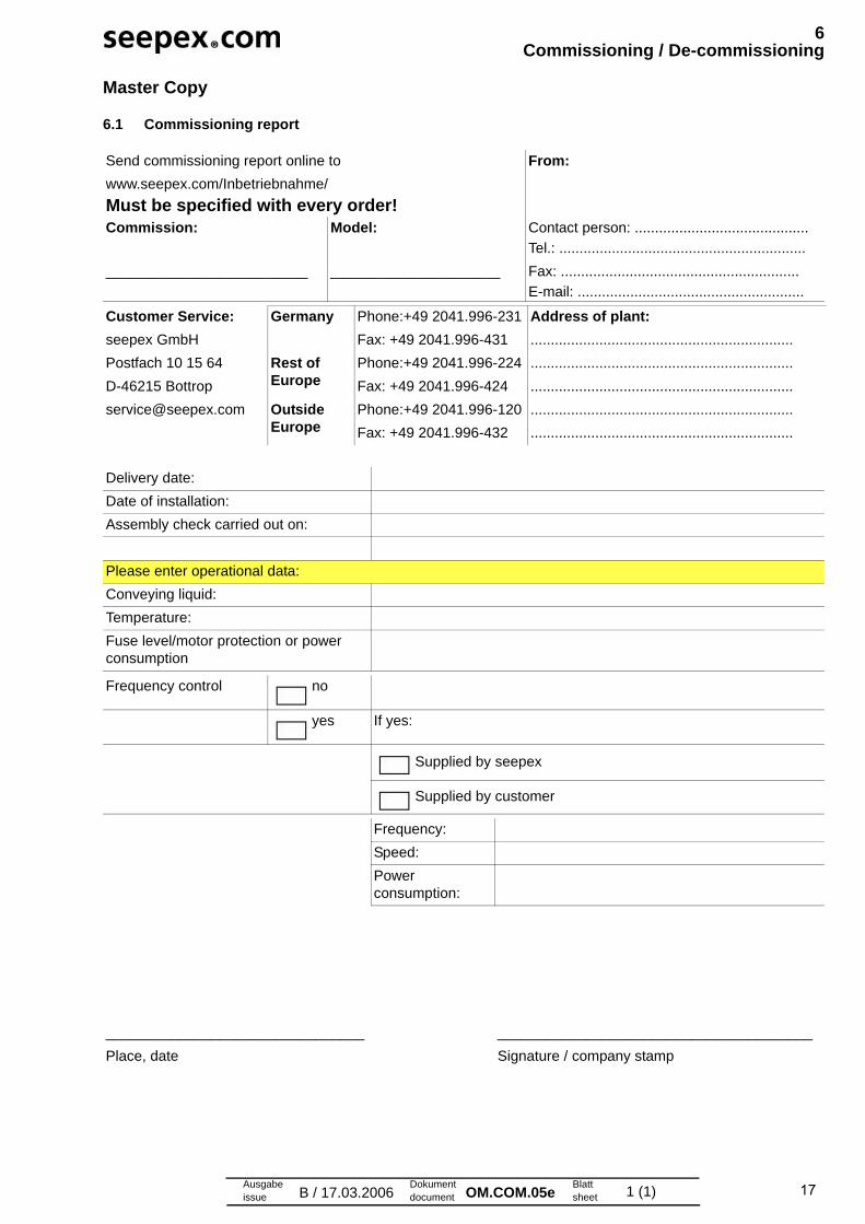
6.1 Commissioning report
Send commissioning report online to
www.seepex.com/Inbetriebnahme/
From:
Must be specified with every order!Commission: Model: Contact person: ...........................................
_________________________ _____________________
Tel.: .............................................................
Fax: ...........................................................
E-mail: ........................................................
Customer Service:seepex GmbH
Postfach 10 15 64
D-46215 Bottrop
Germany Phone:+49 2041.996-231
Fax: +49 2041.996-431
Address of plant: .................................................................
Rest of Europe
Phone:+49 2041.996-224
Fax: +49 2041.996-424
.................................................................
.................................................................
[email protected] Outside Europe
Phone:+49 2041.996-120
Fax: +49 2041.996-432
.................................................................
.................................................................
Delivery date:
Date of installation:
Assembly check carried out on:
Please enter operational data:
Conveying liquid:
Temperature:
Fuse level/motor protection or power consumption
Frequency control no
yes If yes:
Supplied by seepex
Supplied by customer
Frequency:
Speed:
Power consumption:
________________________________ _______________________________________
Place, date Signature / company stamp
18Ausgabeissue B / 18.10.2005
Dokumentdocument OM.COM.01e Blatt
sheet 1 (4)
6Commissioning / De-commissioning
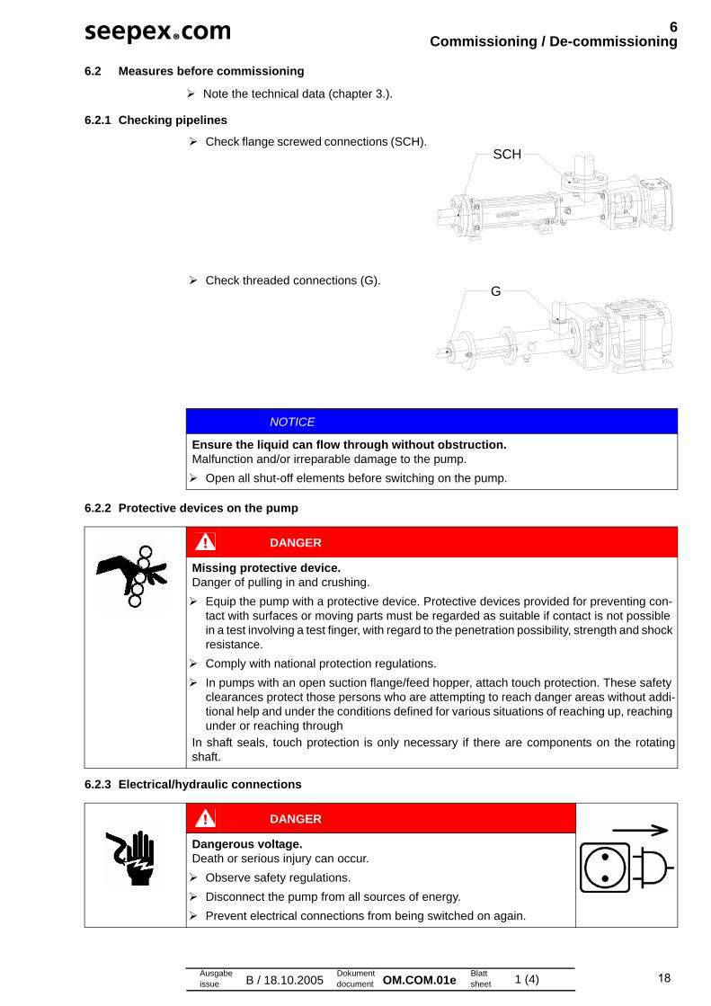
6.2 Measures before commissioning
Note the technical data (chapter 3.).
6.2.1 Checking pipelines
6.2.2 Protective devices on the pump
6.2.3 Electrical/hydraulic connections
Check flange screwed connections (SCH).
Check threaded connections (G).
NOTICE
Ensure the liquid can flow through without obstruction.Malfunction and/or irreparable damage to the pump.
Open all shut-off elements before switching on the pump.
SCH
G
DANGER
Missing protective device.Danger of pulling in and crushing.
Equip the pump with a protective device. Protective devices provided for preventing con-tact with surfaces or moving parts must be regarded as suitable if contact is not possible in a test involving a test finger, with regard to the penetration possibility, strength and shock resistance.
Comply with national protection regulations.
In pumps with an open suction flange/feed hopper, attach touch protection. These safety clearances protect those persons who are attempting to reach danger areas without addi-tional help and under the conditions defined for various situations of reaching up, reaching under or reaching through
In shaft seals, touch protection is only necessary if there are components on the rotatingshaft.
DANGER
Dangerous voltage.Death or serious injury can occur.
Observe safety regulations.
Disconnect the pump from all sources of energy.
Prevent electrical connections from being switched on again.

19
6Commissioning / De-commissioning
Ausgabeissue B / 18.10.2005
Dokumentdocument OM.COM.01e Blatt
sheet 2 (4)
6.2.4 Direction of rotation check
6.2.5 Additional devices - optional Refer to additional devices (chapter 12.1).
6.3 Initial commissioning/repeated commissioning
Start up the pump.
6.3.1 Avoid dry running of the pump
6.3.2 Pressure in the suction and pressure connection
6.4 De-commissioning
Protect the pump and additional devices against the following:
• Frost
• Deposit of solids
• Sedimentation from the liquid
• Corrosion of parts that come into contact with the medium
flow direction
The pump direction of rotation determines the flow direction of the pumping medium.
Note the direction of rotation arrow on the type plate.
counter clockwise clockwise
NOTICE
Dry running of the pump.Malfunction and/or irreparable damage to the pump.
Fill the suction casing with liquid in order to lubricate the pumping elements.
NOTICE
High temperature between rotor and stator.Stator material burned.Complete failure of the pump
Make sure that the suction-side conveying capacity does not cavitate.
If this cannot be guaranteed on the machine side, assemble a seepex dry running
protection (DRP)
CAUTION
High pressure.Malfunction and/or irreparable damage to the shaft seal or pump.
Maintain pressure in the suction connection in accordance with the technical data
(chapter 3.).
Assemble an oil-filled contact pressure gauge to monitor and deactivate the pump.
20
6Commissioning / De-commissioning
Ausgabeissue B / 18.10.2005
Dokumentdocument OM.COM.01e Blatt
sheet 3 (4)
6.4.1 Switching off the pump
6.4.2 Emptying the pump
To drain the pump:
If the pump housing has screwed plugs, remove the screwed plugs.
Drain using a connection branch (suction casing, pressure branch) if the pump housing is coated or the housing does not have screwed plugs.
Drain the residual liquid from the pump housing.
Drain the pipelines on the suction and pressure sides, or shut off behind the pump connec-tions.
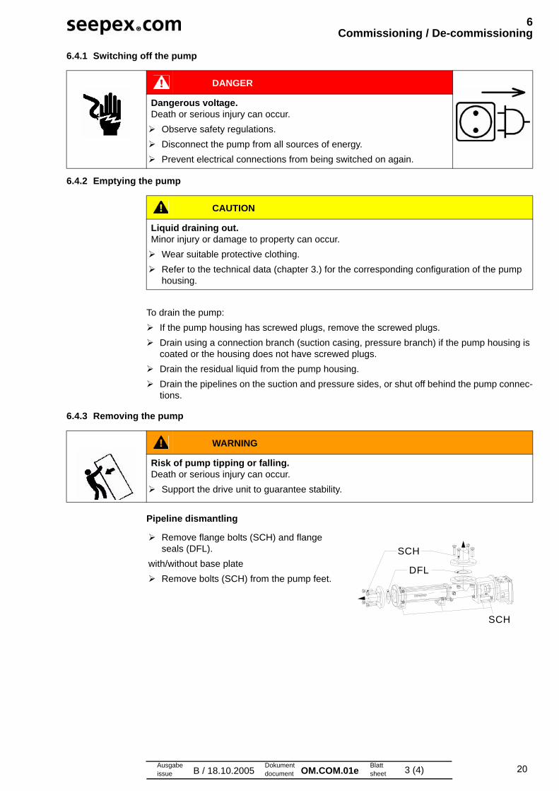
6.4.3 Removing the pump
Pipeline dismantling
DANGER
Dangerous voltage.Death or serious injury can occur.
Observe safety regulations.
Disconnect the pump from all sources of energy.
Prevent electrical connections from being switched on again.
CAUTION
Liquid draining out.Minor injury or damage to property can occur.
Wear suitable protective clothing.
Refer to the technical data (chapter 3.) for the corresponding configuration of the pump housing.
WARNING
Risk of pump tipping or falling.Death or serious injury can occur.
Support the drive unit to guarantee stability.
Remove flange bolts (SCH) and flange seals (DFL).
with/without base plate
Remove bolts (SCH) from the pump feet.DFL
SCH
SCH
21
6Commissioning / De-commissioning
Ausgabeissue B / 18.10.2005
Dokumentdocument OM.COM.01e Blatt
sheet 4 (4)
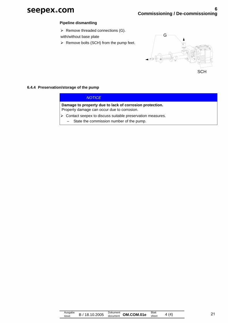
Pipeline dismantling
6.4.4 Preservation/storage of the pump
Remove threaded connections (G).
with/without base plate
Remove bolts (SCH) from the pump feet.
G
SCH
NOTICE
Damage to property due to lack of corrosion protection.Property damage can occur due to corrosion.
Contact seepex to discuss suitable preservation measures.
– State the commission number of the pump.

Ausgabeissue A / 28.06.2007
Dokumentdocument OM.WTG.02e Blatt
sheet 1 (2)
7Maintenance
7.1 Preventive measures
7.1.1 Pump down-time
7.2 Lubrication
7.2.1 Joint grease
The maintenance personnel must have these operating instructions, follow them and also require corresponding qualifications.
• No liability will be accepted in the event of violation.
DANGER
Dangerous voltage.Death or serious injury can occur.
Observe safety regulations.
Disconnect the pump from all sources of energy.
Prevent electrical connections from being switched on again.
NOTICE
Pump down-time.Production failure due to wear.
Acquisition of a set of wearing parts and a set of gaskets.
No. Denomination Lubricant Lubricant change in operating hours
Fill volume
1 Pin joint seepex special grease (30321)
10000 h 7 cm3
2 Pin joint seepex special grease (30321)
10000 h 7 cm3
3 Drive Refer to manufacturer's documentation (chapter 13.1)
Rotor/stator Conveying medium --- ---
Shaft seal Conveying medium --- ---
1 2 3
NOTICE
Other grease types.Malfunction and/or irreparable damage to the joints or the pump.
Exclusively use seepex special grease.
7 Maintenance
Ausgabeissue A / 28.06.2007
Dokumentdocument OM.WTG.02e Blatt
sheet 2 (2)
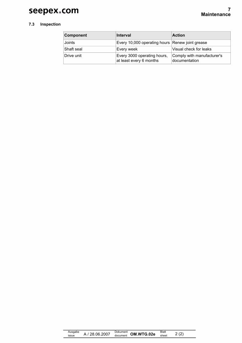
7.3 Inspection
Component Interval Action
Joints Every 10,000 operating hours Renew joint grease
Shaft seal Every week Visual check for leaks
Drive unit Every 3000 operating hours, at least every 6 months
Comply with manufacturer's documentation

Ausgabeissue A / 28.06.2007
Dokumentdocument OM.WTG.03e Blatt
sheet 1 (2)
7 Maintenance
7.1 Preventive measures
7.1.1 Pump down-time
7.2 Lubrication
7.2.1 Joint grease
The maintenance personnel must have these operating instructions, follow them and also require corresponding qualifications.
• No liability will be accepted in the event of violation.
DANGER
Dangerous voltage.Death or serious injury can occur.
Observe safety regulations.
Disconnect the pump from all sources of energy.
Prevent electrical connections from being switched on again.
NOTICE
Pump down-time.Production failure due to wear.
Acquisition of a set of wearing parts and a set of gaskets.
No. Denomination Lubricant Lubricant change in operating hours
Fill volume
1 Pin joint seepex special grease (30321)
10000 h 14 cm3
2 Pin joint seepex special grease (30321)
10000 h 14 cm3
3 Drive Refer to manufacturer's documentation (chapter 13.1)
Rotor/stator Conveying medium --- ---
Shaft seal Conveying medium --- ---
1 2 3
NOTICE
Other grease types.Malfunction and/or irreparable damage to the joints or the pump.
Exclusively use seepex special grease.

7 Maintenance
Ausgabeissue A / 28.06.2007
Dokumentdocument OM.WTG.03e Blatt
sheet 2 (2)
7.3 Inspection
Component Interval Action
Joints Every 10,000 operating hours Renew joint grease
Shaft seal Every week Visual check for leaks
Drive unit Every 3000 operating hours, at least every 6 months
Comply with manufacturer's documentation
22Ausgabeissue A / 18.10.2005
Dokumentdocument OM.WTG.04e Blatt
sheet 1 (2)
7 Maintenance
7.1 Preventive measures
7.1.1 Pump down-time
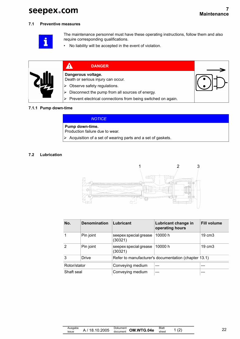
7.2 Lubrication
The maintenance personnel must have these operating instructions, follow them and also require corresponding qualifications.• No liability will be accepted in the event of violation.
DANGER
Dangerous voltage.Death or serious injury can occur.
Observe safety regulations.Disconnect the pump from all sources of energy.Prevent electrical connections from being switched on again.
NOTICE
Pump down-time.Production failure due to wear.
Acquisition of a set of wearing parts and a set of gaskets.
No. Denomination Lubricant Lubricant change in operating hours
Fill volume
1 Pin joint seepex special grease (30321)
10000 h 19 cm3
2 Pin joint seepex special grease (30321)
10000 h 19 cm3
3 Drive Refer to manufacturer's documentation (chapter 13.1)
Rotor/stator Conveying medium --- ---Shaft seal Conveying medium --- ---
1 2 3
23
7 Maintenance
Ausgabeissue A / 18.10.2005
Dokumentdocument OM.WTG.04e Blatt
sheet 2 (2)
7.2.1 Joint grease
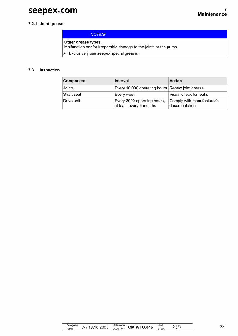
7.3 Inspection
NOTICE
Other grease types.Malfunction and/or irreparable damage to the joints or the pump.
Exclusively use seepex special grease.
Component Interval Action
Joints Every 10,000 operating hours Renew joint greaseShaft seal Every week Visual check for leaksDrive unit Every 3000 operating hours,
at least every 6 monthsComply with manufacturer's documentation

Ausgabeissue A / 28.06.2007
Dokumentdocument OM.WTG.05e Blatt
sheet 1 (2)
7 Maintenance
7.1 Preventive measures
7.1.1 Pump down-time
7.2 Lubrication
7.2.1 Joint grease
The maintenance personnel must have these operating instructions, follow them and also require corresponding qualifications.
• No liability will be accepted in the event of violation.
DANGER
Dangerous voltage.Death or serious injury can occur.
Observe safety regulations.
Disconnect the pump from all sources of energy.
Prevent electrical connections from being switched on again.
NOTICE
Pump down-time.Production failure due to wear.
Acquisition of a set of wearing parts and a set of gaskets.
No. Denomination Lubricant Lubricant change in operating hours
Fill volume
1 Pin joint seepex special grease (30321)
10000 h 32 cm3
2 Pin joint seepex special grease (30321)
10000 h 32 cm3
3 Drive Refer to manufacturer's documentation (chapter 13.1)
Rotor/stator Conveying medium --- ---
Shaft seal Conveying medium --- ---
1 2 3
NOTICE
Other grease types.Malfunction and/or irreparable damage to the joints or the pump.
Exclusively use seepex special grease.

7 Maintenance
Ausgabeissue A / 28.06.2007
Dokumentdocument OM.WTG.05e Blatt
sheet 2 (2)
7.3 Inspection
Component Interval Action
Joints Every 10,000 operating hours Renew joint grease
Shaft seal Every week Visual check for leaks
Drive unit Every 3000 operating hours, at least every 6 months
Comply with manufacturer's documentation
Ausgabeissue A / 28.06.2007
Dokumentdocument OM.WTG.06e Blatt
sheet 1 (2)
7 Maintenance
7.1 Preventive measures
7.1.1 Pump down-time
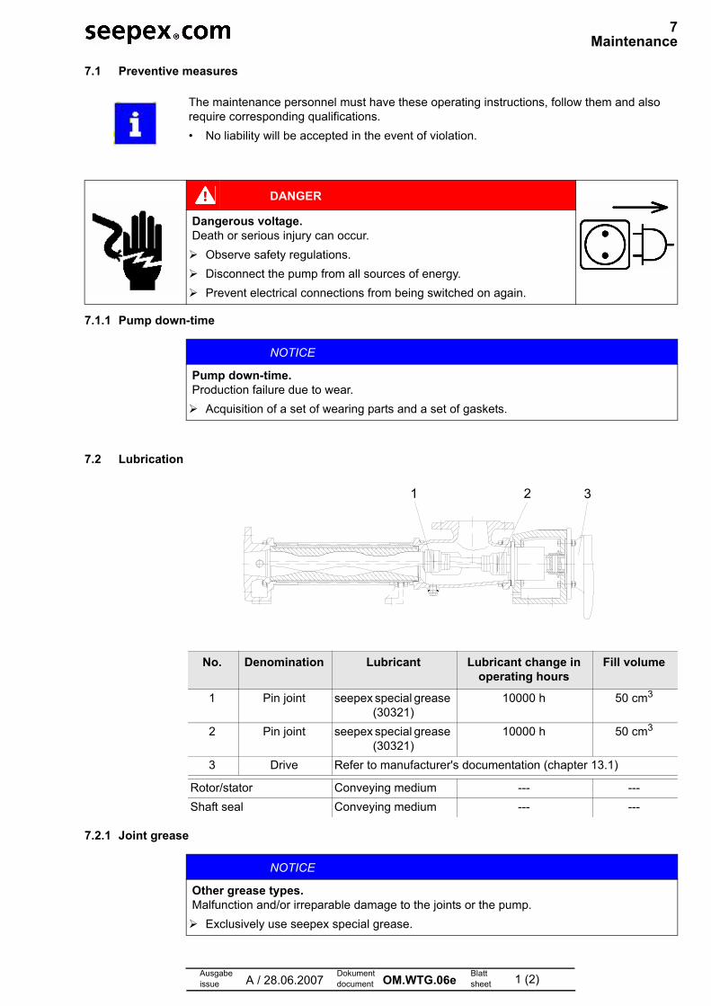
7.2 Lubrication
7.2.1 Joint grease
The maintenance personnel must have these operating instructions, follow them and also require corresponding qualifications.
• No liability will be accepted in the event of violation.
DANGER
Dangerous voltage.Death or serious injury can occur.
Observe safety regulations.
Disconnect the pump from all sources of energy.
Prevent electrical connections from being switched on again.
NOTICE
Pump down-time.Production failure due to wear.
Acquisition of a set of wearing parts and a set of gaskets.
No. Denomination Lubricant Lubricant change in operating hours
Fill volume
1 Pin joint seepex special grease (30321)
10000 h 50 cm3
2 Pin joint seepex special grease (30321)
10000 h 50 cm3
3 Drive Refer to manufacturer's documentation (chapter 13.1)
Rotor/stator Conveying medium --- ---
Shaft seal Conveying medium --- ---
1 2 3
NOTICE
Other grease types.Malfunction and/or irreparable damage to the joints or the pump.
Exclusively use seepex special grease.
7 Maintenance
Ausgabeissue A / 28.06.2007
Dokumentdocument OM.WTG.06e Blatt
sheet 2 (2)
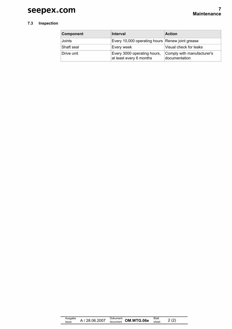
7.3 Inspection
Component Interval Action
Joints Every 10,000 operating hours Renew joint grease
Shaft seal Every week Visual check for leaks
Drive unit Every 3000 operating hours, at least every 6 months
Comply with manufacturer's documentation

Ausgabeissue A / 28.06.2007
Dokumentdocument OM.WTG.07e Blatt
sheet 1 (2)
7 Maintenance
7.1 Preventive measures
7.1.1 Pump down-time
7.2 Lubrication
7.2.1 Joint grease
The maintenance personnel must have these operating instructions, follow them and also require corresponding qualifications.
• No liability will be accepted in the event of violation.
DANGER
Dangerous voltage.Death or serious injury can occur.
Observe safety regulations.
Disconnect the pump from all sources of energy.
Prevent electrical connections from being switched on again.
NOTICE
Pump down-time.Production failure due to wear.
Acquisition of a set of wearing parts and a set of gaskets.
No. Denomination Lubricant Lubricant change in operating hours
Fill volume
1 Pin joint seepex special grease (30321)
10000 h 32 cm3
2 Pin joint seepex special grease (30321)
10000 h 32 cm3
3 Drive Refer to manufacturer's documentation (chapter 13.1)
Rotor/stator Conveying medium --- ---
Shaft seal Conveying medium --- ---
1 2 3
NOTICE
Other grease types.Malfunction and/or irreparable damage to the joints or the pump.
Exclusively use seepex special grease.

7 Maintenance
Ausgabeissue A / 28.06.2007
Dokumentdocument OM.WTG.07e Blatt
sheet 2 (2)
7.3 Inspection
Component Interval Action
Joints Every 10,000 operating hours Renew joint grease
Shaft seal Every week Visual check for leaks
Drive unit Every 3000 operating hours, at least every 6 months
Comply with manufacturer's documentation

Ausgabeissue A / 28.06.2007
Dokumentdocument OM.WTG.08e Blatt
sheet 1 (2)
7 Maintenance
7.1 Preventive measures
7.1.1 Pump down-time
7.2 Lubrication
7.2.1 Joint grease
The maintenance personnel must have these operating instructions, follow them and also require corresponding qualifications.
• No liability will be accepted in the event of violation.
DANGER
Dangerous voltage.Death or serious injury can occur.
Observe safety regulations.
Disconnect the pump from all sources of energy.
Prevent electrical connections from being switched on again.
NOTICE
Pump down-time.Production failure due to wear.
Acquisition of a set of wearing parts and a set of gaskets.
No. Denomination Lubricant Lubricant change in operating hours
Fill volume
1 Pin joint seepex special grease (30321)
10000 h 89 cm3
2 Pin joint seepex special grease (30321)
10000 h 89 cm3
3 Drive Refer to manufacturer's documentation (chapter 13.1)
Rotor/stator Conveying medium --- ---
Shaft seal Conveying medium --- ---
1 2 3
NOTICE
Other grease types.Malfunction and/or irreparable damage to the joints or the pump.
Exclusively use seepex special grease.

7 Maintenance
Ausgabeissue A / 28.06.2007
Dokumentdocument OM.WTG.08e Blatt
sheet 2 (2)
7.3 Inspection
Component Interval Action
Joints Every 10,000 operating hours Renew joint grease
Shaft seal Every week Visual check for leaks
Drive unit Every 3000 operating hours, at least every 6 months
Comply with manufacturer's documentation

Ausgabeissue A / 28.06.2007
Dokumentdocument OM.WTG.09e Blatt
sheet 1 (2)
7 Maintenance
7.1 Preventive measures
7.1.1 Pump down-time
7.2 Lubrication
7.2.1 Joint grease
The maintenance personnel must have these operating instructions, follow them and also require corresponding qualifications.
• No liability will be accepted in the event of violation.
DANGER
Dangerous voltage.Death or serious injury can occur.
Observe safety regulations.
Disconnect the pump from all sources of energy.
Prevent electrical connections from being switched on again.
NOTICE
Pump down-time.Production failure due to wear.
Acquisition of a set of wearing parts and a set of gaskets.
No. Denomination Lubricant Lubricant change in operating hours
Fill volume
1 Pin joint seepex special grease (30321)
10000 h 147 cm3
2 Pin joint seepex special grease (30321)
10000 h 147 cm3
3 Drive Refer to manufacturer's documentation (chapter 13.1)
Rotor/stator Conveying medium --- ---
Shaft seal Conveying medium --- ---
1 2 3
NOTICE
Other grease types.Malfunction and/or irreparable damage to the joints or the pump.
Exclusively use seepex special grease.

7 Maintenance
Ausgabeissue A / 28.06.2007
Dokumentdocument OM.WTG.09e Blatt
sheet 2 (2)
7.3 Inspection
Component Interval Action
Joints Every 10,000 operating hours Renew joint grease
Shaft seal Every week Visual check for leaks
Drive unit Every 3000 operating hours, at least every 6 months
Comply with manufacturer's documentation

Ausgabeissue A / 28.06.2007
Dokumentdocument OM.WTG.10e Blatt
sheet 1 (2)
7 Maintenance
7.1 Preventive measures
7.1.1 Pump down-time
7.2 Lubrication
7.2.1 Joint grease
The maintenance personnel must have these operating instructions, follow them and also require corresponding qualifications.
• No liability will be accepted in the event of violation.
DANGER
Dangerous voltage.Death or serious injury can occur.
Observe safety regulations.
Disconnect the pump from all sources of energy.
Prevent electrical connections from being switched on again.
NOTICE
Pump down-time.Production failure due to wear.
Acquisition of a set of wearing parts and a set of gaskets.
No. Denomination Lubricant Lubricant change in operating hours
Fill volume
1 Pin joint seepex special grease (30321)
10000 h 335.0 cm3
2 Pin joint seepex special grease (30321)
10000 h 335.0 cm3
3 Drive Refer to manufacturer's documentation (chapter 13.1)
Rotor/stator Conveying medium --- ---
Shaft seal Conveying medium --- ---
1 2 3
NOTICE
Other grease types.Malfunction and/or irreparable damage to the joints or the pump.
Exclusively use seepex special grease.

7 Maintenance
Ausgabeissue A / 28.06.2007
Dokumentdocument OM.WTG.10e Blatt
sheet 2 (2)
7.3 Inspection
Component Interval Action
Joints Every 10,000 operating hours Renew joint grease
Shaft seal Every week Visual check for leaks
Drive unit Every 3000 operating hours, at least every 6 months
Comply with manufacturer's documentation

Ausgabeissue A / 28.06.2007
Dokumentdocument OM.WTG.11e Blatt
sheet 1 (2)
7 Maintenance
7.1 Preventive measures
7.1.1 Pump down-time
7.2 Lubrication
7.2.1 Joint grease
The maintenance personnel must have these operating instructions, follow them and also require corresponding qualifications.
• No liability will be accepted in the event of violation.
DANGER
Dangerous voltage.Death or serious injury can occur.
Observe safety regulations.
Disconnect the pump from all sources of energy.
Prevent electrical connections from being switched on again.
NOTICE
Pump down-time.Production failure due to wear.
Acquisition of a set of wearing parts and a set of gaskets.
No. Denomination Lubricant Lubricant change in operating hours
Fill volume
1 Pin joint seepex special grease (30321)
10000 h 916 cm3
2 Pin joint seepex special grease (30321)
10000 h 916 cm3
3 Drive Refer to manufacturer's documentation (chapter 13.1)
Rotor/stator Conveying medium --- ---
Shaft seal Conveying medium --- ---
1 2 3
NOTICE
Other grease types.Malfunction and/or irreparable damage to the joints or the pump.
Exclusively use seepex special grease.

7 Maintenance
Ausgabeissue A / 28.06.2007
Dokumentdocument OM.WTG.11e Blatt
sheet 2 (2)
7.3 Inspection
Component Interval Action
Joints Every 10,000 operating hours Renew joint grease
Shaft seal Every week Visual check for leaks
Drive unit Every 3000 operating hours, at least every 6 months
Comply with manufacturer's documentation

Ausgabeissue A / 28.06.2007
Dokumentdocument OM.WTG.13e Blatt
sheet 1 (2)
7 Maintenance
7.1 Preventive measures
7.1.1 Pump down-time
7.2 Lubrication
7.2.1 Joint grease
The maintenance personnel must have these operating instructions, follow them and also require corresponding qualifications.
• No liability will be accepted in the event of violation.
DANGER
Dangerous voltage.Death or serious injury can occur.
Observe safety regulations.
Disconnect the pump from all sources of energy.
Prevent electrical connections from being switched on again.
NOTICE
Pump down-time.Production failure due to wear.
Acquisition of a set of wearing parts and a set of gaskets.
No. Denomination Lubricant Lubricant change in operating hours
Fill volume
1 Pin joint seepex special grease (10325)
10000 h 7 cm3
2 Pin joint seepex special grease (10325)
10000 h 7 cm3
3 Drive Refer to manufacturer's documentation (chapter 13.1)
Rotor/stator Conveying medium --- ---
Shaft seal Conveying medium --- ---
1 2 3
NOTICE
Other grease types.Malfunction and/or irreparable damage to the joints or the pump.
Exclusively use seepex special grease.

7 Maintenance
Ausgabeissue A / 28.06.2007
Dokumentdocument OM.WTG.13e Blatt
sheet 2 (2)
7.3 Inspection
Component Interval Action
Joints Every 10,000 operating hours Renew joint grease
Shaft seal Every week Visual check for leaks
Drive unit Every 3000 operating hours, at least every 6 months
Comply with manufacturer's documentation

Ausgabeissue A / 28.06.2007
Dokumentdocument OM.WTG.14e Blatt
sheet 1 (2)
7 Maintenance
7.1 Preventive measures
7.1.1 Pump down-time
7.2 Lubrication
7.2.1 Joint grease
The maintenance personnel must have these operating instructions, follow them and also require corresponding qualifications.
• No liability will be accepted in the event of violation.
DANGER
Dangerous voltage.Death or serious injury can occur.
Observe safety regulations.
Disconnect the pump from all sources of energy.
Prevent electrical connections from being switched on again.
NOTICE
Pump down-time.Production failure due to wear.
Acquisition of a set of wearing parts and a set of gaskets.
No. Denomination Lubricant Lubricant change in operating hours
Fill volume
1 Pin joint seepex special grease (10325)
10000 h 14 cm3
2 Pin joint seepex special grease (10325)
10000 h 14 cm3
3 Drive Refer to manufacturer's documentation (chapter 13.1)
Rotor/stator Conveying medium --- ---
Shaft seal Conveying medium --- ---
1 2 3
NOTICE
Other grease types.Malfunction and/or irreparable damage to the joints or the pump.
Exclusively use seepex special grease.

7 Maintenance
Ausgabeissue A / 28.06.2007
Dokumentdocument OM.WTG.14e Blatt
sheet 2 (2)
7.3 Inspection
Component Interval Action
Joints Every 10,000 operating hours Renew joint grease
Shaft seal Every week Visual check for leaks
Drive unit Every 3000 operating hours, at least every 6 months
Comply with manufacturer's documentation

Ausgabeissue A / 28.06.2007
Dokumentdocument OM.WTG.15e Blatt
sheet 1 (2)
7 Maintenance
7.1 Preventive measures
7.1.1 Pump down-time
7.2 Lubrication
7.2.1 Joint grease
The maintenance personnel must have these operating instructions, follow them and also require corresponding qualifications.
• No liability will be accepted in the event of violation.
DANGER
Dangerous voltage.Death or serious injury can occur.
Observe safety regulations.
Disconnect the pump from all sources of energy.
Prevent electrical connections from being switched on again.
NOTICE
Pump down-time.Production failure due to wear.
Acquisition of a set of wearing parts and a set of gaskets.
No. Denomination Lubricant Lubricant change in operating hours
Fill volume
1 Pin joint seepex special grease (10325)
10000 h 19 cm3
2 Pin joint seepex special grease (10325)
10000 h 19 cm3
3 Drive Refer to manufacturer's documentation (chapter 13.1)
Rotor/stator Conveying medium --- ---
Shaft seal Conveying medium --- ---
1 2 3
NOTICE
Other grease types.Malfunction and/or irreparable damage to the joints or the pump.
Exclusively use seepex special grease.

7 Maintenance
Ausgabeissue A / 28.06.2007
Dokumentdocument OM.WTG.15e Blatt
sheet 2 (2)
7.3 Inspection
Component Interval Action
Joints Every 10,000 operating hours Renew joint grease
Shaft seal Every week Visual check for leaks
Drive unit Every 3000 operating hours, at least every 6 months
Comply with manufacturer's documentation

Ausgabeissue A / 28.06.2007
Dokumentdocument OM.WTG.16e Blatt
sheet 1 (2)
7 Maintenance
7.1 Preventive measures
7.1.1 Pump down-time
7.2 Lubrication
7.2.1 Joint grease
The maintenance personnel must have these operating instructions, follow them and also require corresponding qualifications.
• No liability will be accepted in the event of violation.
DANGER
Dangerous voltage.Death or serious injury can occur.
Observe safety regulations.
Disconnect the pump from all sources of energy.
Prevent electrical connections from being switched on again.
NOTICE
Pump down-time.Production failure due to wear.
Acquisition of a set of wearing parts and a set of gaskets.
No. Denomination Lubricant Lubricant change in operating hours
Fill volume
1 Pin joint seepex special grease (10325)
10000 h 32 cm3
2 Pin joint seepex special grease (10325)
10000 h 32 cm3
3 Drive Refer to manufacturer's documentation (chapter 13.1)
Rotor/stator Conveying medium --- ---
Shaft seal Conveying medium --- ---
1 2 3
NOTICE
Other grease types.Malfunction and/or irreparable damage to the joints or the pump.
Exclusively use seepex special grease.

7 Maintenance
Ausgabeissue A / 28.06.2007
Dokumentdocument OM.WTG.16e Blatt
sheet 2 (2)
7.3 Inspection
Component Interval Action
Joints Every 10,000 operating hours Renew joint grease
Shaft seal Every week Visual check for leaks
Drive unit Every 3000 operating hours, at least every 6 months
Comply with manufacturer's documentation

Ausgabeissue A / 28.06.2007
Dokumentdocument OM.WTG.17e Blatt
sheet 1 (2)
7 Maintenance
7.1 Preventive measures
7.1.1 Pump down-time
7.2 Lubrication
7.2.1 Joint grease
The maintenance personnel must have these operating instructions, follow them and also require corresponding qualifications.
• No liability will be accepted in the event of violation.
DANGER
Dangerous voltage.Death or serious injury can occur.
Observe safety regulations.
Disconnect the pump from all sources of energy.
Prevent electrical connections from being switched on again.
NOTICE
Pump down-time.Production failure due to wear.
Acquisition of a set of wearing parts and a set of gaskets.
No. Denomination Lubricant Lubricant change in operating hours
Fill volume
1 Pin joint seepex special grease (10325)
10000 h 50 cm3
2 Pin joint seepex special grease (10325)
10000 h 50 cm3
3 Drive Refer to manufacturer's documentation (chapter 13.1)
Rotor/stator Conveying medium --- ---
Shaft seal Conveying medium --- ---
1 2 3
NOTICE
Other grease types.Malfunction and/or irreparable damage to the joints or the pump.
Exclusively use seepex special grease.

7 Maintenance
Ausgabeissue A / 28.06.2007
Dokumentdocument OM.WTG.17e Blatt
sheet 2 (2)
7.3 Inspection
Component Interval Action
Joints Every 10,000 operating hours Renew joint grease
Shaft seal Every week Visual check for leaks
Drive unit Every 3000 operating hours, at least every 6 months
Comply with manufacturer's documentation

Ausgabeissue A / 28.06.2007
Dokumentdocument OM.WTG.18e Blatt
sheet 1 (2)
7 Maintenance
7.1 Preventive measures
7.1.1 Pump down-time
7.2 Lubrication
7.2.1 Joint grease
The maintenance personnel must have these operating instructions, follow them and also require corresponding qualifications.
• No liability will be accepted in the event of violation.
DANGER
Dangerous voltage.Death or serious injury can occur.
Observe safety regulations.
Disconnect the pump from all sources of energy.
Prevent electrical connections from being switched on again.
NOTICE
Pump down-time.Production failure due to wear.
Acquisition of a set of wearing parts and a set of gaskets.
No. Denomination Lubricant Lubricant change in operating hours
Fill volume
1 Pin joint seepex special grease (10325)
10000 h 64 cm3
2 Pin joint seepex special grease (10325)
10000 h 64 cm3
3 Drive Refer to manufacturer's documentation (chapter 13.1)
Rotor/stator Conveying medium --- ---
Shaft seal Conveying medium --- ---
1 2 3
NOTICE
Other grease types.Malfunction and/or irreparable damage to the joints or the pump.
Exclusively use seepex special grease.

7 Maintenance
Ausgabeissue A / 28.06.2007
Dokumentdocument OM.WTG.18e Blatt
sheet 2 (2)
7.3 Inspection
Component Interval Action
Joints Every 10,000 operating hours Renew joint grease
Shaft seal Every week Visual check for leaks
Drive unit Every 3000 operating hours, at least every 6 months
Comply with manufacturer's documentation

Ausgabeissue A / 28.06.2007
Dokumentdocument OM.WTG.19e Blatt
sheet 1 (2)
7 Maintenance
7.1 Preventive measures
7.1.1 Pump down-time
7.2 Lubrication
7.2.1 Joint grease
The maintenance personnel must have these operating instructions, follow them and also require corresponding qualifications.
• No liability will be accepted in the event of violation.
DANGER
Dangerous voltage.Death or serious injury can occur.
Observe safety regulations.
Disconnect the pump from all sources of energy.
Prevent electrical connections from being switched on again.
NOTICE
Pump down-time.Production failure due to wear.
Acquisition of a set of wearing parts and a set of gaskets.
No. Denomination Lubricant Lubricant change in operating hours
Fill volume
1 Pin joint seepex special grease (10325)
10000 h 89 cm3
2 Pin joint seepex special grease (10325)
10000 h 89 cm3
3 Drive Refer to manufacturer's documentation (chapter 13.1)
Rotor/stator Conveying medium --- ---
Shaft seal Conveying medium --- ---
1 2 3
NOTICE
Other grease types.Malfunction and/or irreparable damage to the joints or the pump.
Exclusively use seepex special grease.

7 Maintenance
Ausgabeissue A / 28.06.2007
Dokumentdocument OM.WTG.19e Blatt
sheet 2 (2)
7.3 Inspection
Component Interval Action
Joints Every 10,000 operating hours Renew joint grease
Shaft seal Every week Visual check for leaks
Drive unit Every 3000 operating hours, at least every 6 months
Comply with manufacturer's documentation

Ausgabeissue A / 28.06.2007
Dokumentdocument OM.WTG.20e Blatt
sheet 1 (2)
7 Maintenance
7.1 Preventive measures
7.1.1 Pump down-time
7.2 Lubrication
7.2.1 Joint grease
The maintenance personnel must have these operating instructions, follow them and also require corresponding qualifications.
• No liability will be accepted in the event of violation.
DANGER
Dangerous voltage.Death or serious injury can occur.
Observe safety regulations.
Disconnect the pump from all sources of energy.
Prevent electrical connections from being switched on again.
NOTICE
Pump down-time.Production failure due to wear.
Acquisition of a set of wearing parts and a set of gaskets.
No. Denomination Lubricant Lubricant change in operating hours
Fill volume
1 Pin joint seepex special grease (10325)
10000 h 147 cm3
2 Pin joint seepex special grease (10325)
10000 h 147 cm3
3 Drive Refer to manufacturer's documentation (chapter 13.1)
Rotor/stator Conveying medium --- ---
Shaft seal Conveying medium --- ---
1 2 3
NOTICE
Other grease types.Malfunction and/or irreparable damage to the joints or the pump.
Exclusively use seepex special grease.

7 Maintenance
Ausgabeissue A / 28.06.2007
Dokumentdocument OM.WTG.20e Blatt
sheet 2 (2)
7.3 Inspection
Component Interval Action
Joints Every 10,000 operating hours Renew joint grease
Shaft seal Every week Visual check for leaks
Drive unit Every 3000 operating hours, at least every 6 months
Comply with manufacturer's documentation

Ausgabeissue A / 28.06.2007
Dokumentdocument OM.WTG.21e Blatt
sheet 1 (2)
7 Maintenance
7.1 Preventive measures
7.1.1 Pump down-time
7.2 Lubrication
7.2.1 Joint grease
The maintenance personnel must have these operating instructions, follow them and also require corresponding qualifications.
• No liability will be accepted in the event of violation.
DANGER
Dangerous voltage.Death or serious injury can occur.
Observe safety regulations.
Disconnect the pump from all sources of energy.
Prevent electrical connections from being switched on again.
NOTICE
Pump down-time.Production failure due to wear.
Acquisition of a set of wearing parts and a set of gaskets.
No. Denomination Lubricant Lubricant change in operating hours
Fill volume
1 Pin joint seepex special grease (10325)
10000 h 335 cm3
2 Pin joint seepex special grease (10325)
10000 h 335 cm3
3 Drive Refer to manufacturer's documentation (chapter 13.1)
Rotor/stator Conveying medium --- ---
Shaft seal Conveying medium --- ---
1 2 3
NOTICE
Other grease types.Malfunction and/or irreparable damage to the joints or the pump.
Exclusively use seepex special grease.

7 Maintenance
Ausgabeissue A / 28.06.2007
Dokumentdocument OM.WTG.21e Blatt
sheet 2 (2)
7.3 Inspection
Component Interval Action
Joints Every 10,000 operating hours Renew joint grease
Shaft seal Every week Visual check for leaks
Drive unit Every 3000 operating hours, at least every 6 months
Comply with manufacturer's documentation

Ausgabeissue A / 28.06.2007
Dokumentdocument OM.WTG.22e Blatt
sheet 1 (2)
7 Maintenance
7.1 Preventive measures
7.1.1 Pump down-time
7.2 Lubrication
7.2.1 Joint grease
The maintenance personnel must have these operating instructions, follow them and also require corresponding qualifications.
• No liability will be accepted in the event of violation.
DANGER
Dangerous voltage.Death or serious injury can occur.
Observe safety regulations.
Disconnect the pump from all sources of energy.
Prevent electrical connections from being switched on again.
NOTICE
Pump down-time.Production failure due to wear.
Acquisition of a set of wearing parts and a set of gaskets.
No. Denomination Lubricant Lubricant change in operating hours
Fill volume
1 Pin joint seepex special grease (10325)
10000 h 916 cm3
2 Pin joint seepex special grease (10325)
10000 h 916 cm3
3 Drive Refer to manufacturer's documentation (chapter 13.1)
Rotor/stator Conveying medium --- ---
Shaft seal Conveying medium --- ---
1 2 3
NOTICE
Other grease types.Malfunction and/or irreparable damage to the joints or the pump.
Exclusively use seepex special grease.

7 Maintenance
Ausgabeissue A / 28.06.2007
Dokumentdocument OM.WTG.22e Blatt
sheet 2 (2)
7.3 Inspection
Component Interval Action
Joints Every 10,000 operating hours Renew joint grease
Shaft seal Every week Visual check for leaks
Drive unit Every 3000 operating hours, at least every 6 months
Comply with manufacturer's documentation

Ausgabeissue A / 28.06.2007
Dokumentdocument OM.WTG.24e Blatt
sheet 1 (2)
7 Maintenance
7.1 Preventive measures
7.1.1 Pump down-time
7.2 Lubrication
7.2.1 Joint grease
The maintenance personnel must have these operating instructions, follow them and also require corresponding qualifications.
• No liability will be accepted in the event of violation.
DANGER
Dangerous voltage.Death or serious injury can occur.
Observe safety regulations.
Disconnect the pump from all sources of energy.
Prevent electrical connections from being switched on again.
NOTICE
Pump down-time.Production failure due to wear.
Acquisition of a set of wearing parts and a set of gaskets.
No. Denomination Lubricant Lubricant change in operating hours
Fill volume
1 Pin joint seepex special grease (30322)
10000 h 7 cm3
2 Pin joint seepex special grease (30322)
10000 h 7 cm3
3 Drive Refer to manufacturer's documentation (chapter 13.1)
Rotor/stator Conveying medium --- ---
Shaft seal Conveying medium --- ---
1 2 3
NOTICE
Other grease types.Malfunction and/or irreparable damage to the joints or the pump.
Exclusively use seepex special grease.

7 Maintenance
Ausgabeissue A / 28.06.2007
Dokumentdocument OM.WTG.24e Blatt
sheet 2 (2)
7.3 Inspection
Component Interval Action
Joints Every 10,000 operating hours Renew joint grease
Shaft seal Every week Visual check for leaks
Drive unit Every 3000 operating hours, at least every 6 months
Comply with manufacturer's documentation

Ausgabeissue A / 28.06.2007
Dokumentdocument OM.WTG.25e Blatt
sheet 1 (2)
7 Maintenance
7.1 Preventive measures
7.1.1 Pump down-time
7.2 Lubrication
7.2.1 Joint grease
The maintenance personnel must have these operating instructions, follow them and also require corresponding qualifications.
• No liability will be accepted in the event of violation.
DANGER
Dangerous voltage.Death or serious injury can occur.
Observe safety regulations.
Disconnect the pump from all sources of energy.
Prevent electrical connections from being switched on again.
NOTICE
Pump down-time.Production failure due to wear.
Acquisition of a set of wearing parts and a set of gaskets.
No. Denomination Lubricant Lubricant change in operating hours
Fill volume
1 Pin joint seepex special grease (30322)
10000 h 14 cm3
2 Pin joint seepex special grease (30322)
10000 h 14 cm3
3 Drive Refer to manufacturer's documentation (chapter 13.1)
Rotor/stator Conveying medium --- ---
Shaft seal Conveying medium --- ---
1 2 3
NOTICE
Other grease types.Malfunction and/or irreparable damage to the joints or the pump.
Exclusively use seepex special grease.

7 Maintenance
Ausgabeissue A / 28.06.2007
Dokumentdocument OM.WTG.25e Blatt
sheet 2 (2)
7.3 Inspection
Component Interval Action
Joints Every 10,000 operating hours Renew joint grease
Shaft seal Every week Visual check for leaks
Drive unit Every 3000 operating hours, at least every 6 months
Comply with manufacturer's documentation

Ausgabeissue A / 28.06.2007
Dokumentdocument OM.WTG.26e Blatt
sheet 1 (2)
7Maintenance
7.1 Preventive measures
7.1.1 Pump down-time
7.2 Lubrication
7.2.1 Joint grease
The maintenance personnel must have these operating instructions, follow them and also require corresponding qualifications.
• No liability will be accepted in the event of violation.
DANGER
Dangerous voltage.Death or serious injury can occur.
Observe safety regulations.
Disconnect the pump from all sources of energy.
Prevent electrical connections from being switched on again.
NOTICE
Pump down-time.Production failure due to wear.
Acquisition of a set of wearing parts and a set of gaskets.
No. Denomination Lubricant Lubricant change in operating hours
Fill volume
1 Pin joint seepex special grease (30322)
10000 h 19 cm3
2 Pin joint seepex special grease (30322)
10000 h 19 cm3
3 Drive Refer to manufacturer's documentation (chapter 13.1)
Rotor/stator Conveying medium --- ---
Shaft seal Conveying medium --- ---
1 2 3
NOTICE
Other grease types.Malfunction and/or irreparable damage to the joints or the pump.
Exclusively use seepex special grease.

7 Maintenance
Ausgabeissue A / 28.06.2007
Dokumentdocument OM.WTG.26e Blatt
sheet 2 (2)
7.3 Inspection
Component Interval Action
Joints Every 10,000 operating hours Renew joint grease
Shaft seal Every week Visual check for leaks
Drive unit Every 3000 operating hours, at least every 6 months
Comply with manufacturer's documentation

Ausgabeissue A / 28.06.2007
Dokumentdocument OM.WTG.27e Blatt
sheet 1 (2)
7Maintenance
7.1 Preventive measures
7.1.1 Pump down-time
7.2 Lubrication
7.2.1 Joint grease
The maintenance personnel must have these operating instructions, follow them and also require corresponding qualifications.
• No liability will be accepted in the event of violation.
DANGER
Dangerous voltage.Death or serious injury can occur.
Observe safety regulations.
Disconnect the pump from all sources of energy.
Prevent electrical connections from being switched on again.
NOTICE
Pump down-time.Production failure due to wear.
Acquisition of a set of wearing parts and a set of gaskets.
No. Denomination Lubricant Lubricant change in operating hours
Fill volume
1 Pin joint seepex special grease (30322)
10000 h 32 cm3
2 Pin joint seepex special grease (30322)
10000 h 32 cm3
3 Drive Refer to manufacturer's documentation (chapter 13.1)
Rotor/stator Conveying medium --- ---
Shaft seal Conveying medium --- ---
1 2 3
NOTICE
Other grease types.Malfunction and/or irreparable damage to the joints or the pump.
Exclusively use seepex special grease.

7 Maintenance
Ausgabeissue A / 28.06.2007
Dokumentdocument OM.WTG.27e Blatt
sheet 2 (2)
7.3 Inspection
Component Interval Action
Joints Every 10,000 operating hours Renew joint grease
Shaft seal Every week Visual check for leaks
Drive unit Every 3000 operating hours, at least every 6 months
Comply with manufacturer's documentation

Ausgabeissue A / 28.06.2007
Dokumentdocument OM.WTG.28e Blatt
sheet 1 (2)
7Maintenance
7.1 Preventive measures
7.1.1 Pump down-time
7.2 Lubrication
7.2.1 Joint grease
The maintenance personnel must have these operating instructions, follow them and also require corresponding qualifications.
• No liability will be accepted in the event of violation.
DANGER
Dangerous voltage.Death or serious injury can occur.
Observe safety regulations.
Disconnect the pump from all sources of energy.
Prevent electrical connections from being switched on again.
NOTICE
Pump down-time.Production failure due to wear.
Acquisition of a set of wearing parts and a set of gaskets.
No. Denomination Lubricant Lubricant change in operating hours
Fill volume
1 Pin joint seepex special grease (30322)
10000 h 50 cm3
2 Pin joint seepex special grease (30322)
10000 h 50 cm3
3 Drive Refer to manufacturer's documentation (chapter 13.1)
Rotor/stator Conveying medium --- ---
Shaft seal Conveying medium --- ---
1 2 3
NOTICE
Other grease types.Malfunction and/or irreparable damage to the joints or the pump.
Exclusively use seepex special grease.

7 Maintenance
Ausgabeissue A / 28.06.2007
Dokumentdocument OM.WTG.28e Blatt
sheet 2 (2)
7.3 Inspection
Component Interval Action
Joints Every 10,000 operating hours Renew joint grease
Shaft seal Every week Visual check for leaks
Drive unit Every 3000 operating hours, at least every 6 months
Comply with manufacturer's documentation
Ausgabeissue A / 28.06.2007
Dokumentdocument OM.WTG.29e Blatt
sheet 1 (2)
7Maintenance
7.1 Preventive measures
7.1.1 Pump down-time
7.2 Lubrication
7.2.1 Joint grease
The maintenance personnel must have these operating instructions, follow them and also require corresponding qualifications.
• No liability will be accepted in the event of violation.
DANGER
Dangerous voltage.Death or serious injury can occur.
Observe safety regulations.
Disconnect the pump from all sources of energy.
Prevent electrical connections from being switched on again.
NOTICE
Pump down-time.Production failure due to wear.
Acquisition of a set of wearing parts and a set of gaskets.
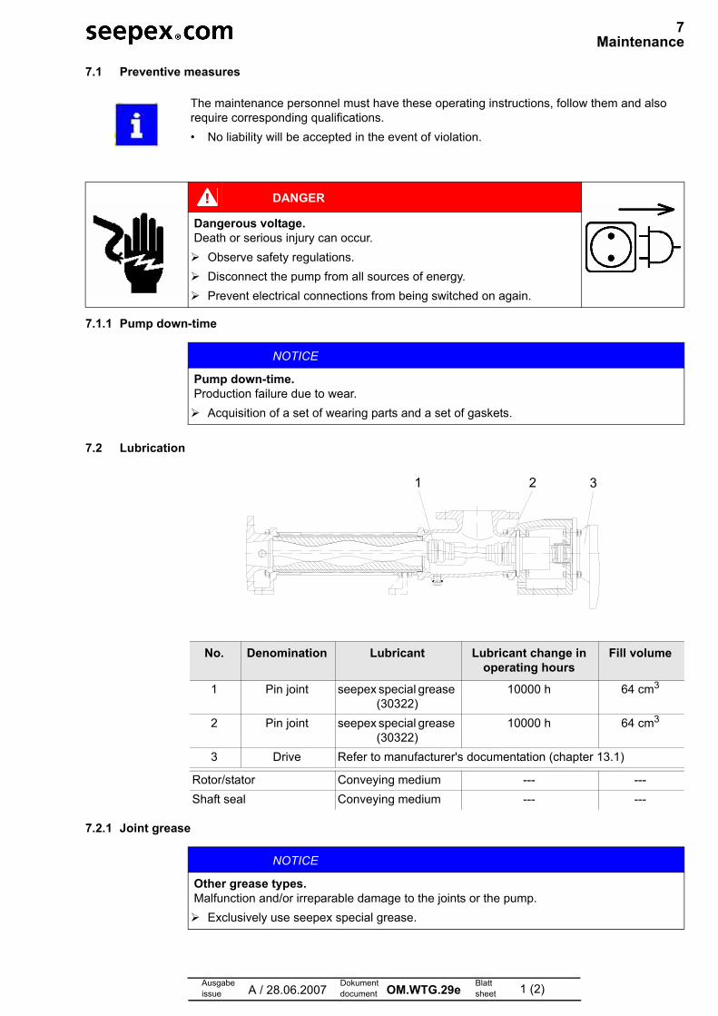
No. Denomination Lubricant Lubricant change in operating hours
Fill volume
1 Pin joint seepex special grease (30322)
10000 h 64 cm3
2 Pin joint seepex special grease (30322)
10000 h 64 cm3
3 Drive Refer to manufacturer's documentation (chapter 13.1)
Rotor/stator Conveying medium --- ---
Shaft seal Conveying medium --- ---
1 2 3
NOTICE
Other grease types.Malfunction and/or irreparable damage to the joints or the pump.
Exclusively use seepex special grease.

7 Maintenance
Ausgabeissue A / 28.06.2007
Dokumentdocument OM.WTG.29e Blatt
sheet 2 (2)
7.3 Inspection
Component Interval Action
Joints Every 10,000 operating hours Renew joint grease
Shaft seal Every week Visual check for leaks
Drive unit Every 3000 operating hours, at least every 6 months
Comply with manufacturer's documentation

Ausgabeissue A / 28.06.2007
Dokumentdocument OM.WTG.30e Blatt
sheet 1 (2)
7 Maintenance
7.1 Preventive measures
7.1.1 Pump down-time
7.2 Lubrication
7.2.1 Joint grease
The maintenance personnel must have these operating instructions, follow them and also require corresponding qualifications.
• No liability will be accepted in the event of violation.
DANGER
Dangerous voltageDeath or serious injury can occur
Observe safety regulations
Disconnect the pump from all sources of energy
NOTICE
Pump down-time.Production failure due to wear.
Acquisition of a set of wearing parts and a set of gaskets.
No. Denomination Lubricant Lubricant change in operating hours
Fill volume
1 Pin joint seepex special grease (30322)
10000 h 89 cm3
2 Pin joint seepex special grease (30322)
10000 h 89 cm3
3 Drive Refer to manufacturer's documentation (chapter 13.1)
Rotor/stator Conveying medium --- ---
Shaft seal Conveying medium --- ---
1 2 3
NOTICE
Other grease types.Malfunction and/or irreparable damage to the joints or the pump.
Exclusively use seepex special grease.

7 Maintenance
Ausgabeissue A / 28.06.2007
Dokumentdocument OM.WTG.30e Blatt
sheet 2 (2)
7.3 Inspection
Component Interval Action
Joints Every 10,000 operating hours Renew joint grease
Shaft seal Every week Visual check for leaks
Drive unit Every 3000 operating hours, at least every 6 months
Comply with manufacturer's documentation
Ausgabeissue A / 28.06.2007
Dokumentdocument OM.WTG.31e Blatt
sheet 1 (2)
7 Maintenance
7.1 Preventive measures
7.1.1 Pump down-time
7.2 Lubrication
7.2.1 Joint grease
The maintenance personnel must have these operating instructions, follow them and also require corresponding qualifications.
• No liability will be accepted in the event of violation.
DANGER
Dangerous voltageDeath or serious injury can occur
Observe safety regulations
Disconnect the pump from all sources of energy
NOTICE
Pump down-time.Production failure due to wear.
Acquisition of a set of wearing parts and a set of gaskets.
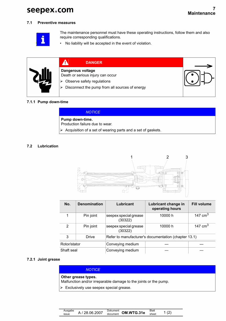
No. Denomination Lubricant Lubricant change in operating hours
Fill volume
1 Pin joint seepex special grease (30322)
10000 h 147 cm3
2 Pin joint seepex special grease (30322)
10000 h 147 cm3
3 Drive Refer to manufacturer's documentation (chapter 13.1)
Rotor/stator Conveying medium --- ---
Shaft seal Conveying medium --- ---
1 2 3
NOTICE
Other grease types.Malfunction and/or irreparable damage to the joints or the pump.
Exclusively use seepex special grease.

7 Maintenance
Ausgabeissue A / 28.06.2007
Dokumentdocument OM.WTG.31e Blatt
sheet 2 (2)
7.3 Inspection
Component Interval Action
Joints Every 10,000 operating hours Renew joint grease
Shaft seal Every week Visual check for leaks
Drive unit Every 3000 operating hours, at least every 6 months
Comply with manufacturer's documentation

Ausgabeissue A / 28.06.2007
Dokumentdocument OM.WTG.32e Blatt
sheet 1 (2)
7 Maintenance
7.1 Preventive measures
7.1.1 Pump down-time
7.2 Lubrication
7.2.1 Joint grease
The maintenance personnel must have these operating instructions, follow them and also require corresponding qualifications.
• No liability will be accepted in the event of violation.
DANGER
Dangerous voltage.Death or serious injury can occur.
Observe safety regulations.
Disconnect the pump from all sources of energy.
Prevent electrical connections from being switched on again.
NOTICE
Pump down-time.Production failure due to wear.
Acquisition of a set of wearing parts and a set of gaskets.
No. Denomination Lubricant Lubricant change in operating hours
Fill volume
1 Pin joint seepex special grease (30322)
10000 h 335 cm3
2 Pin joint seepex special grease (30322)
10000 h 335 cm3
3 Drive Refer to manufacturer's documentation (chapter 13.1)
Rotor/stator Conveying medium --- ---
Shaft seal Conveying medium --- ---
1 2 3
NOTICE
Other grease types.Malfunction and/or irreparable damage to the joints or the pump.
Exclusively use seepex special grease.

7 Maintenance
Ausgabeissue A / 28.06.2007
Dokumentdocument OM.WTG.32e Blatt
sheet 2 (2)
7.3 Inspection
Component Interval Action
Joints Every 10,000 operating hours Renew joint grease
Shaft seal Every week Visual check for leaks
Drive unit Every 3000 operating hours, at least every 6 months
Comply with manufacturer's documentation

Ausgabeissue A / 28.06.2007
Dokumentdocument OM.WTG.33e Blatt
sheet 1 (2)
7 Maintenance
7.1 Preventive measures
7.1.1 Pump down-time
7.2 Lubrication
7.2.1 Joint grease
The maintenance personnel must have these operating instructions, follow them and also require corresponding qualifications.
• No liability will be accepted in the event of violation.
DANGER
Dangerous voltageDeath or serious injury can occur
Observe safety regulations
Disconnect the pump from all sources of energy
NOTICE
Pump down-time.Production failure due to wear.
Acquisition of a set of wearing parts and a set of gaskets.
No. Denomination Lubricant Lubricant change in operating hours
Fill volume
1 Pin joint seepex special grease (30322)
10000 h 916 cm3
2 Pin joint seepex special grease (30322)
10000 h 916 cm3
3 Drive Refer to manufacturer's documentation (chapter 13.1)
Rotor/stator Conveying medium --- ---
Shaft seal Conveying medium --- ---
1 2 3
NOTICE
Other grease types.Malfunction and/or irreparable damage to the joints or the pump.
Exclusively use seepex special grease.

7 Maintenance
Ausgabeissue A / 28.06.2007
Dokumentdocument OM.WTG.33e Blatt
sheet 2 (2)
7.3 Inspection
Component Interval Action
Joints Every 10,000 operating hours Renew joint grease
Shaft seal Every week Visual check for leaks
Drive unit Every 3000 operating hours, at least every 6 months
Comply with manufacturer's documentation
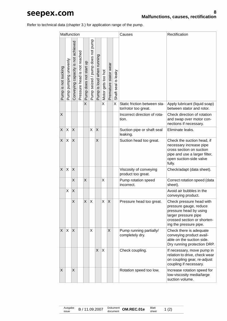
Ausgabeissue B / 11.09.2007 Dokument
document OM.REC.01e Blattsheet 1 (2)
8Malfunctions, causes, rectification
Refer to technical data (chapter 3.) for application range of the pump.
Malfunction Causes Rectification
Pum
p is
not
suc
king
Pum
p pu
mpi
ng u
neve
nly
Con
veyi
ng c
apac
ity is
not
ach
ieve
dP
ress
ure
head
is n
ot re
ache
dP
ump
does
not
sta
rt up
Pum
p se
ized
/ pu
mp
does
not
pum
pP
ump
is lo
ud w
hen
runn
ing
Mot
or g
ets
too
hot
Pre
mat
ure
stat
or w
ear
Sha
ft se
al is
leak
y
X X X Static friction between sta-tor/rotor too great.
Apply lubricant (liquid soap) between stator and rotor.
X Incorrect direction of rota-tion.
Check direction of rotation and swap over motor con-nections if necessary.
X X X X X Suction pipe or shaft seal leaking.
Eliminate leaks.
X X X X Suction head too great. Check the suction head, if necessary increase pipe cross section on suction pipe and use a larger filter, open suction-side valve fully.
X X X Viscosity of conveying product too great.
Check/adapt (data sheet).
X X X Pump rotation speed incorrect.
Correct rotation speed (data sheet).
X X Avoid air bubbles in the conveying product.
X X X X X Pressure head too great. Check pressure head with pressure gauge, reduce pressure head by using larger pressure pipe crossed section or shorten-ing the pressure pipe.
X X X X X Pump running partially/completely dry.
Check there is adequate conveying product avail-able on the suction side. Dry running protection DRP.
X X Check coupling. If necessary, move pump in relation to drive, check wear on coupling gear, re-adjust coupling if necessary.
X X Rotation speed too low. Increase rotation speed for low-viscosity media/large suction volume.
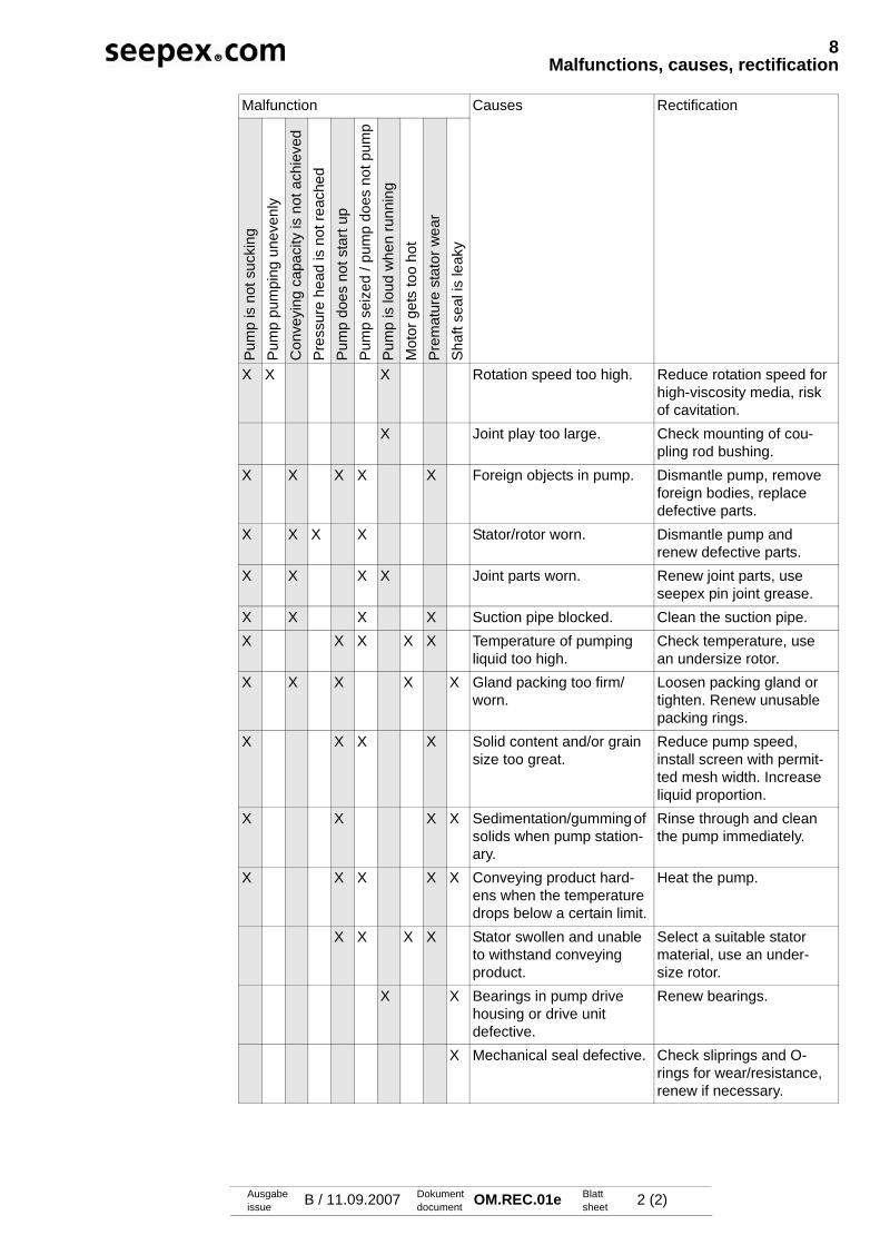
8Malfunctions, causes, rectification
Ausgabeissue B / 11.09.2007 Dokument
document OM.REC.01e Blattsheet 2 (2)
Malfunction Causes Rectification
Pum
p is
not
suc
king
Pum
p pu
mpi
ng u
neve
nly
Con
veyi
ng c
apac
ity is
not
ach
ieve
dP
ress
ure
head
is n
ot re
ache
dP
ump
does
not
sta
rt up
Pum
p se
ized
/ pu
mp
does
not
pum
pP
ump
is lo
ud w
hen
runn
ing
Mot
or g
ets
too
hot
Pre
mat
ure
stat
or w
ear
Sha
ft se
al is
leak
y
X X X Rotation speed too high. Reduce rotation speed for high-viscosity media, risk of cavitation.
X Joint play too large. Check mounting of cou-pling rod bushing.
X X X X X Foreign objects in pump. Dismantle pump, remove foreign bodies, replace defective parts.
X X X X Stator/rotor worn. Dismantle pump and renew defective parts.
X X X X Joint parts worn. Renew joint parts, use seepex pin joint grease.
X X X X Suction pipe blocked. Clean the suction pipe.X X X X X Temperature of pumping
liquid too high.Check temperature, use an undersize rotor.
X X X X X Gland packing too firm/worn.
Loosen packing gland or tighten. Renew unusable packing rings.
X X X X Solid content and/or grain size too great.
Reduce pump speed, install screen with permit-ted mesh width. Increase liquid proportion.
X X X X Sedimentation/gumming of solids when pump station-ary.
Rinse through and clean the pump immediately.
X X X X X Conveying product hard-ens when the temperature drops below a certain limit.
Heat the pump.
X X X X Stator swollen and unable to withstand conveying product.
Select a suitable stator material, use an under-size rotor.
X X Bearings in pump drive housing or drive unit defective.
Renew bearings.
X Mechanical seal defective. Check sliprings and O-rings for wear/resistance, renew if necessary.
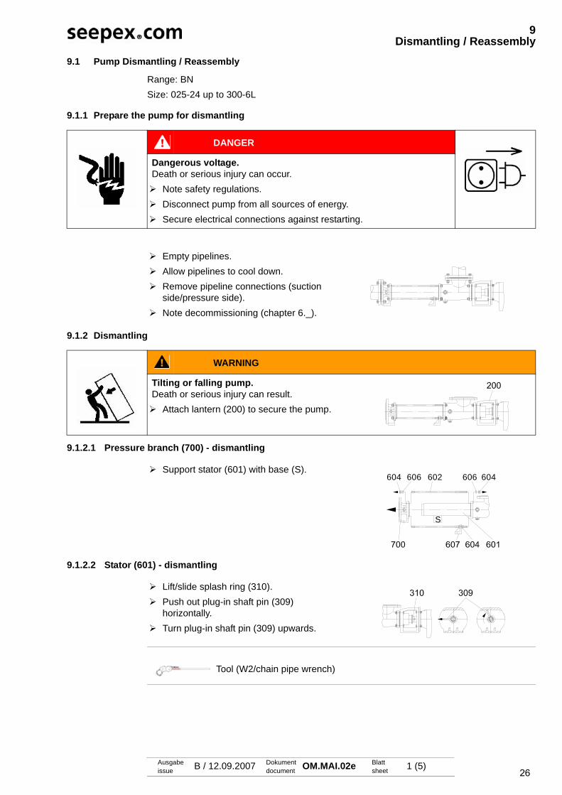
26Ausgabeissue B / 12.09.2007 Dokument
document OM.MAI.02e Blattsheet 1 (5)
9Dismantling / Reassembly
9.1 Pump Dismantling / Reassembly
Range: BNSize: 025-24 up to 300-6L
9.1.1 Prepare the pump for dismantling
9.1.2 Dismantling
9.1.2.1 Pressure branch (700) - dismantling
9.1.2.2 Stator (601) - dismantling
DANGER
Dangerous voltage. Death or serious injury can occur. Note safety regulations. Disconnect pump from all sources of energy. Secure electrical connections against restarting.
Empty pipelines. Allow pipelines to cool down. Remove pipeline connections (suction
side/pressure side). Note decommissioning (chapter 6._).
WARNING
Tilting or falling pump.Death or serious injury can result. Attach lantern (200) to secure the pump.
Support stator (601) with base (S).604 606 602 606 604
S
Lift/slide splash ring (310). Push out plug-in shaft pin (309)
horizontally. Turn plug-in shaft pin (309) upwards.
Tool (W2/chain pipe wrench)
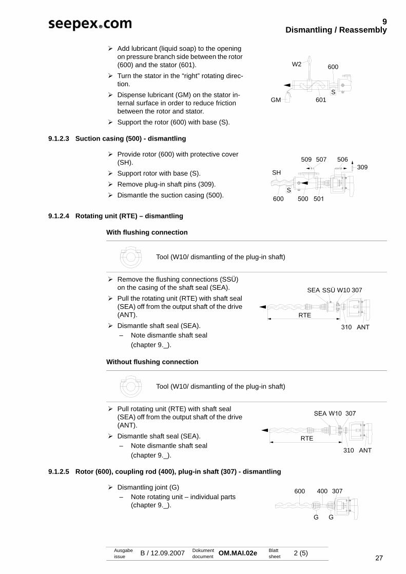
27
9Dismantling / Reassembly
Ausgabeissue B / 12.09.2007 Dokument
document OM.MAI.02e Blattsheet 2 (5)
9.1.2.3 Suction casing (500) - dismantling
9.1.2.4 Rotating unit (RTE) – dismantling
With flushing connection
Without flushing connection
9.1.2.5 Rotor (600), coupling rod (400), plug-in shaft (307) - dismantling
Add lubricant (liquid soap) to the opening on pressure branch side between the rotor (600) and the stator (601).
Turn the stator in the “right” rotating direc-tion.
Dispense lubricant (GM) on the stator in-ternal surface in order to reduce friction between the rotor and stator.
Support the rotor (600) with base (S).
600
S601
W2
GM
Provide rotor (600) with protective cover (SH).
Support rotor with base (S). Remove plug-in shaft pins (309). Dismantle the suction casing (500).
509 507 506
S
SH309
Tool (W10/ dismantling of the plug-in shaft)
Remove the flushing connections (SSÜ) on the casing of the shaft seal (SEA).
Pull the rotating unit (RTE) with shaft seal (SEA) off from the output shaft of the drive (ANT).
Dismantle shaft seal (SEA).– Note dismantle shaft seal
(chapter 9._).
Tool (W10/ dismantling of the plug-in shaft)
Pull rotating unit (RTE) with shaft seal (SEA) off from the output shaft of the drive (ANT).
Dismantle shaft seal (SEA). – Note dismantle shaft seal
(chapter 9._).
W10SEA
RTE
307SSÜ
RTE
310 ANT
Dismantling joint (G)– Note rotating unit – individual parts
(chapter 9._).
600 400 307
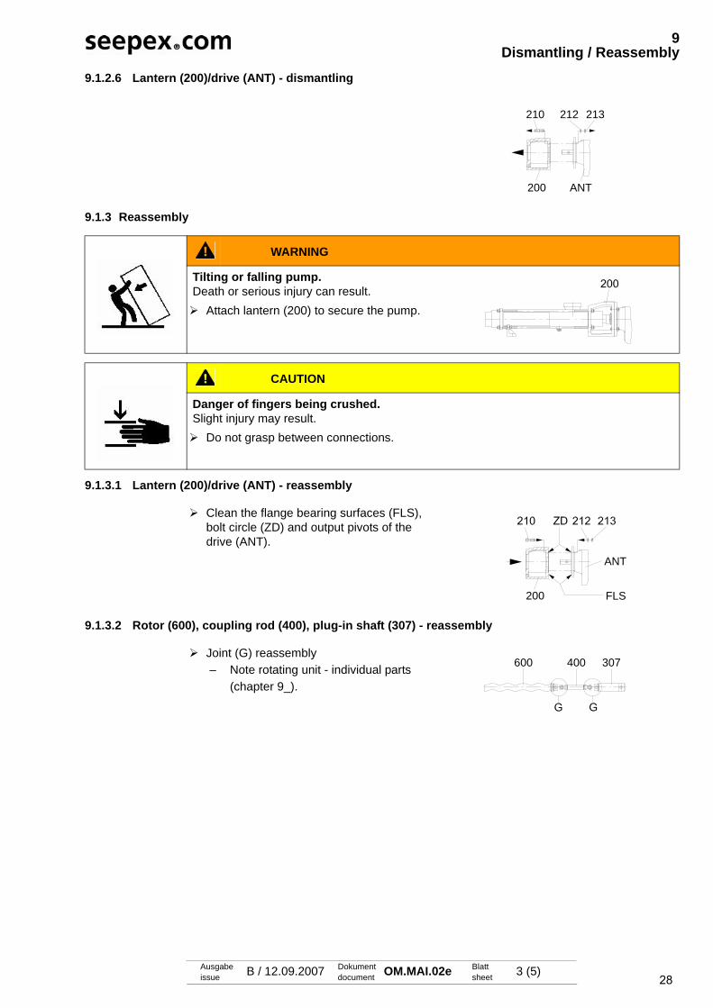
28
9Dismantling / Reassembly
Ausgabeissue B / 12.09.2007 Dokument
document OM.MAI.02e Blattsheet 3 (5)
9.1.2.6 Lantern (200)/drive (ANT) - dismantling
9.1.3 Reassembly
9.1.3.1 Lantern (200)/drive (ANT) - reassembly
9.1.3.2 Rotor (600), coupling rod (400), plug-in shaft (307) - reassembly
213212210
200 ANT
WARNING
Tilting or falling pump.Death or serious injury can result. Attach lantern (200) to secure the pump.
CAUTION
Danger of fingers being crushed.Slight injury may result. Do not grasp between connections.
Clean the flange bearing surfaces (FLS), bolt circle (ZD) and output pivots of the drive (ANT).
ANT
FLS200
Joint (G) reassembly – Note rotating unit - individual parts
(chapter 9_).
600 400 307
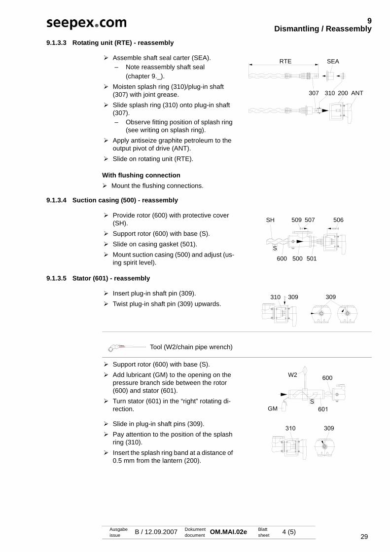
29
9Dismantling / Reassembly
Ausgabeissue B / 12.09.2007 Dokument
document OM.MAI.02e Blattsheet 4 (5)
9.1.3.3 Rotating unit (RTE) - reassembly
With flushing connection Mount the flushing connections.
9.1.3.4 Suction casing (500) - reassembly
9.1.3.5 Stator (601) - reassembly
Assemble shaft seal carter (SEA).– Note reassembly shaft seal
(chapter 9._). Moisten splash ring (310)/plug-in shaft
(307) with joint grease. Slide splash ring (310) onto plug-in shaft
(307). – Observe fitting position of splash ring
(see writing on splash ring). Apply antiseize graphite petroleum to the
output pivot of drive (ANT). Slide on rotating unit (RTE).
RTE SEA
307 310 200 ANT
Provide rotor (600) with protective cover (SH).
Support rotor (600) with base (S). Slide on casing gasket (501). Mount suction casing (500) and adjust (us-
ing spirit level).
509 507 506SH
S
600 500 501
Insert plug-in shaft pin (309). Twist plug-in shaft pin (309) upwards.
Tool (W2/chain pipe wrench)
Support rotor (600) with base (S). Add lubricant (GM) to the opening on the
pressure branch side between the rotor (600) and stator (601).
Turn stator (601) in the “right” rotating di-rection.
Slide in plug-in shaft pins (309). Pay attention to the position of the splash
ring (310). Insert the splash ring band at a distance of
0.5 mm from the lantern (200).
310 309309
600W2
SGM
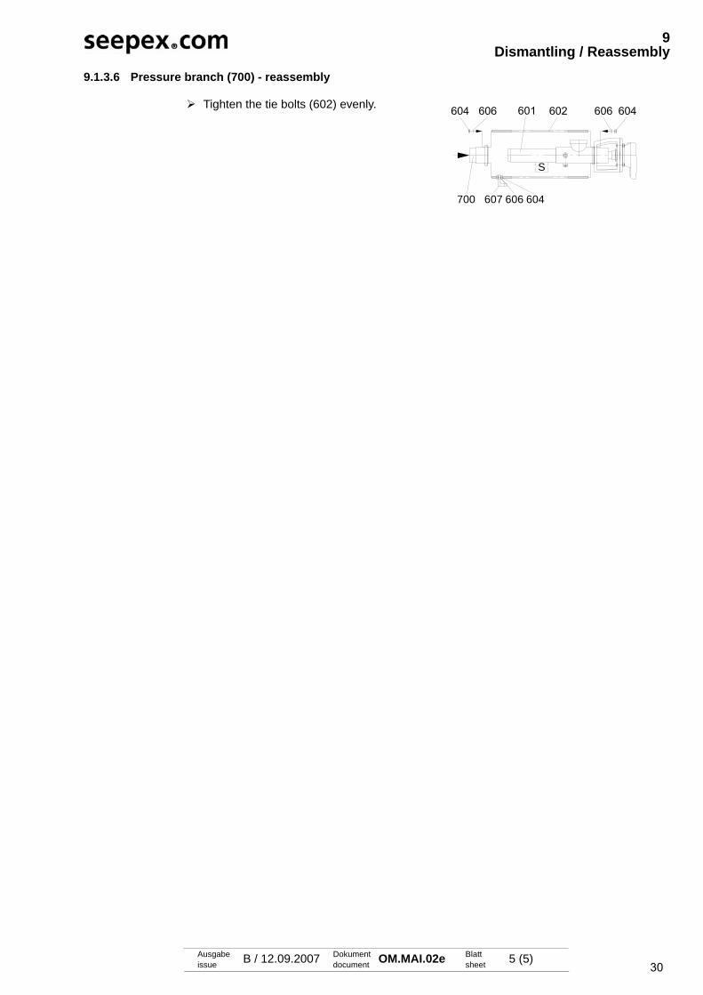
30
9Dismantling / Reassembly
Ausgabeissue B / 12.09.2007 Dokument
document OM.MAI.02e Blattsheet 5 (5)
9.1.3.6 Pressure branch (700) - reassembly
Tighten the tie bolts (602) evenly.
S
700 607 606 604

31Ausgabeissue D / 06.07.2007 Dokument
document OM.PJT.02e Blattsheet 1 (4)
9Dismantling / Reassembly
9.2 Rotating unit individual parts
9.2.1 Dismantling
9.2.1.1 Holding band (406, 407) - dismantling
9.2.1.2 Retaining sleeve (401) - dismantling
9.2.1.3 Detach joint
CAUTION
Risk of injury.Possibility of parts spinning out. Wear protective goggles.
Detach holding band loop (SCL).– Use suitable tool (WM).
Push out parts of holding band loop (SCL). Remove holding band (406, 407). Pull back universal joint sleeve (405).
SCL
Knock back retaining sleeve (401).– Use suitable tool (WM).
WM401
Tool (W5/drift)
Eject coupling rod pins (402). Bend (A) the coupling rod (400). Knock
guide bushing (403) out with tool (W5). Remove coupling rod (400).
W5403 404 400
402403
A
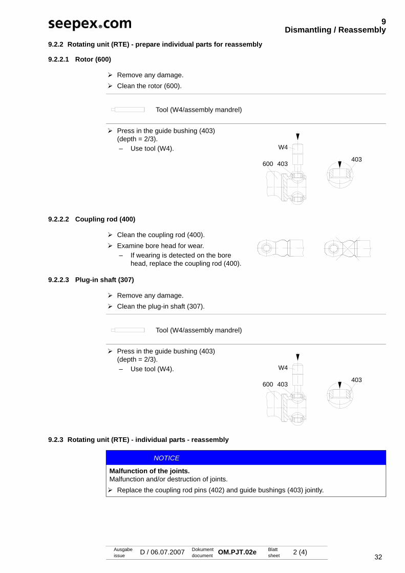
32
9Dismantling / Reassembly
Ausgabeissue D / 06.07.2007 Dokument
document OM.PJT.02e Blattsheet 2 (4)
9.2.2 Rotating unit (RTE) - prepare individual parts for reassembly
9.2.2.1 Rotor (600)
9.2.2.2 Coupling rod (400)
9.2.2.3 Plug-in shaft (307)
9.2.3 Rotating unit (RTE) - individual parts - reassembly
Remove any damage. Clean the rotor (600).
Tool (W4/assembly mandrel)
Press in the guide bushing (403) (depth = 2/3).– Use tool (W4).
600 403
W4
403
Clean the coupling rod (400). Examine bore head for wear.
– If wearing is detected on the bore head, replace the coupling rod (400).
Remove any damage. Clean the plug-in shaft (307).
Tool (W4/assembly mandrel)
Press in the guide bushing (403) (depth = 2/3).– Use tool (W4).
600 403
W4
403
NOTICE
Malfunction of the joints.Malfunction and/or destruction of joints. Replace the coupling rod pins (402) and guide bushings (403) jointly.
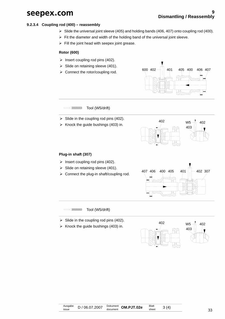
33
9Dismantling / Reassembly
Ausgabeissue D / 06.07.2007 Dokument
document OM.PJT.02e Blattsheet 3 (4)
9.2.3.4 Coupling rod (400) – reassembly Slide the universal joint sleeve (405) and holding bands (406, 407) onto coupling rod (400). Fit the diameter and width of the holding band of the universal joint sleeve. Fill the joint head with seepex joint grease.
Rotor (600)
Plug-in shaft (307)
Insert coupling rod pins (402). Slide on retaining sleeve (401). Connect the rotor/coupling rod.
Tool (W5/drift)
Slide in the coupling rod pins (402). Knock the guide bushings (403) in.
Insert coupling rod pins (402). Slide on retaining sleeve (401). Connect the plug-in shaft/coupling rod.
Tool (W5/drift)
Slide in the coupling rod pins (402). Knock the guide bushings (403) in.
402 401 400405 406 407600
402 402W5403
400 307402401405407 406
402 402W5403

34
9Dismantling / Reassembly
Ausgabeissue D / 06.07.2007 Dokument
document OM.PJT.02e Blattsheet 4 (4)
9.2.3.5 Retaining sleeve (401) - reassembly
Rotor (600) unhardened material
Rotor (600) hardened material
9.2.3.6 Universal joint sleeve (405) - reassembly
Tool (W4/assembly mandrel)
Knock back retaining sleeve (401).– Use tool (W4).
Secure retaining sleeve (401) in a dis-placed manner (2x180°).– Use suitable tool (WK).
Secure retaining sleeve (401) in a dis-placed manner (2x180°).– Use suitable tool (WK).
401W4
401 WK
401 WK
Moisten the surface of the coupling rod (400)/ inner surface of the universal joint sleeve (405) with joint grease (mainte-nance, chapter 7.0).
Slide on the universal joint sleeve (405).
Vent the interior of the joint.– Use suitable tool (WS).
Assemble holding band.– Holding band assembly
(chapter 9._).
400 405
405 WS
407 405 406
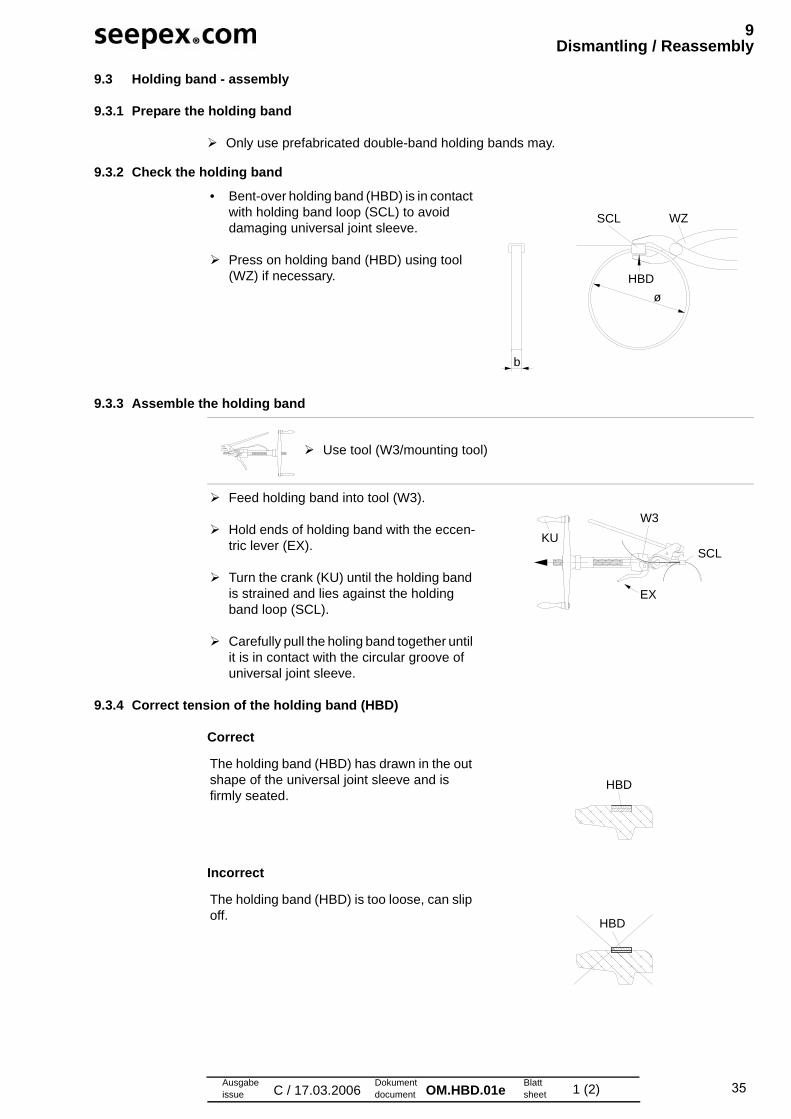
35Ausgabeissue C / 17.03.2006
Dokumentdocument OM.HBD.01e Blatt
sheet 1 (2)
9Dismantling / Reassembly
9.3 Holding band - assembly
9.3.1 Prepare the holding band
Only use prefabricated double-band holding bands may.
9.3.2 Check the holding band
9.3.3 Assemble the holding band
9.3.4 Correct tension of the holding band (HBD)
Correct
Incorrect
• Bent-over holding band (HBD) is in contact with holding band loop (SCL) to avoid damaging universal joint sleeve.
Press on holding band (HBD) using tool (WZ) if necessary.
SCL WZ
HBD
ø
b
Use tool (W3/mounting tool)
Feed holding band into tool (W3).
Hold ends of holding band with the eccen-tric lever (EX).
Turn the crank (KU) until the holding band is strained and lies against the holding band loop (SCL).
Carefully pull the holing band together until it is in contact with the circular groove of universal joint sleeve.
W3
SCL
EX
KU
The holding band (HBD) has drawn in the out shape of the universal joint sleeve and is firmly seated.
The holding band (HBD) is too loose, can slip off.
HBD
HBD
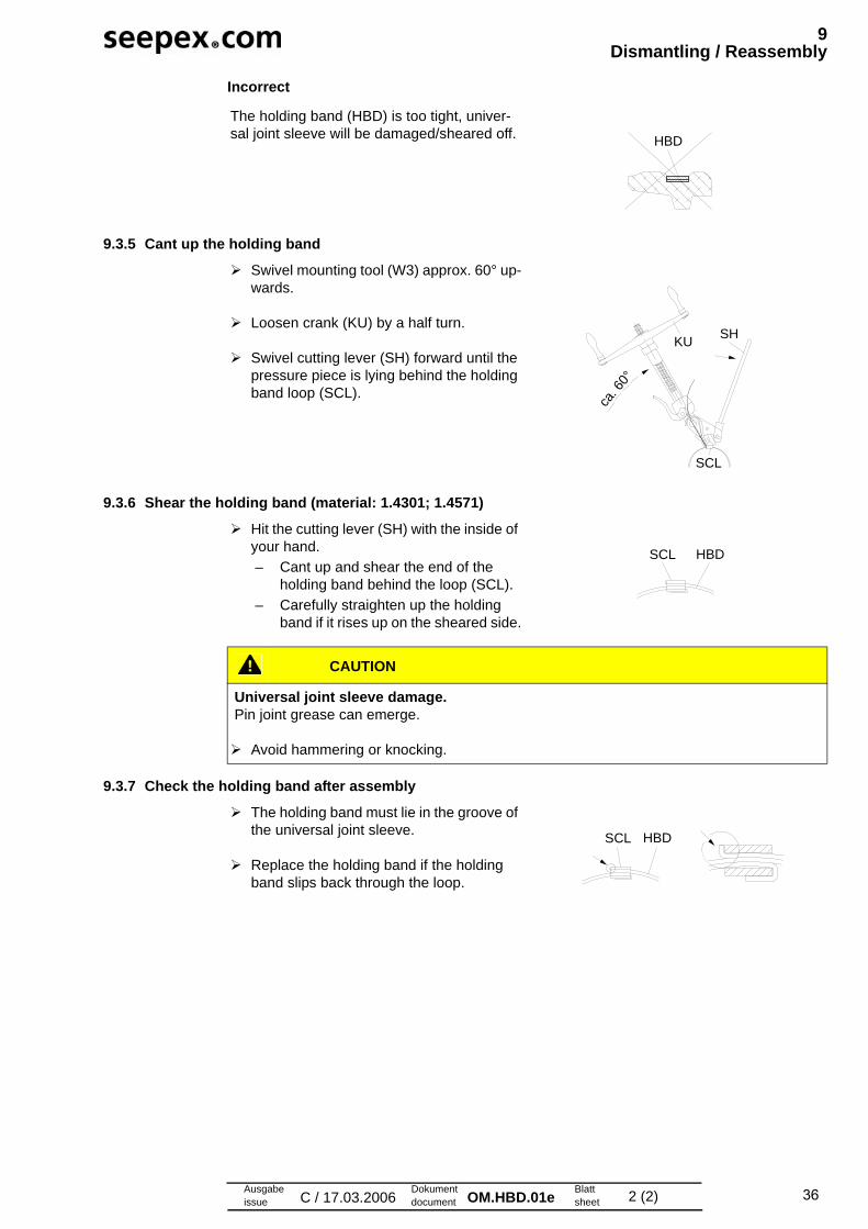
36
9Dismantling / Reassembly
Ausgabeissue C / 17.03.2006
Dokumentdocument OM.HBD.01e Blatt
sheet 2 (2)
Incorrect
9.3.5 Cant up the holding band
9.3.6 Shear the holding band (material: 1.4301; 1.4571)
9.3.7 Check the holding band after assembly
The holding band (HBD) is too tight, univer-sal joint sleeve will be damaged/sheared off. HBD
Swivel mounting tool (W3) approx. 60° up-wards.
Loosen crank (KU) by a half turn.
Swivel cutting lever (SH) forward until the pressure piece is lying behind the holding band loop (SCL).
KUSH
ca. 6
0°
SCL
Hit the cutting lever (SH) with the inside of your hand.
– Cant up and shear the end of the holding band behind the loop (SCL).
– Carefully straighten up the holding band if it rises up on the sheared side.
CAUTION
Universal joint sleeve damage.Pin joint grease can emerge.
Avoid hammering or knocking.
SCL HBD
The holding band must lie in the groove of the universal joint sleeve.
Replace the holding band if the holding band slips back through the loop.
SCL HBD

37Ausgabeissue B / 06.06.2007
Dokumentdocument OM.SEA.02e Blatt
sheet 1 (3)
9Dismantling / Reassembly
9.1 Shaft sealing single acting
9.1.1 Safety
9.1.2 Application conditions and material version• Refer to the relevant application
– technical data (Chapter 3.)
9.1.3 Design
9.1.4 Commissioning
Circulation, flushing and/or flushing pipe• Additional flushing or circulation pipes are not required where shaft sealing lies in medium. • Flushing pipes may be possible under special circumstances and after speaking to seepex.
Adjust shaft sealing It is absolutely vital to adjust at the application site in a manner appropriate for the applica-tion conditions.Refer to the sectional drawing of the shaft sealing for setting measurements. Set the setting measurements of the shaft sealing to the plug-in shaft (307).
WARNING
Shaft sealing is leaky.Leakage may escape into the atmosphere.
Take safety measures to protect persons and the environment. Wear suitable protective clothing.Dispose of leakage appropriately.Heed applicable regulations when handling hazardous substances.
• Single acting mechanical seal
307
333SEA
NOTICE
Dry running of the mechanical seal.Damage to property may result.
The mechanical seal must be laid in liquid medium before being commissioned.
NOTICE
Shaft sealing is not leakage free.Damage to property through leakage.
Components which come into contact with leakage must be corrosion-resistant or other-wise suitably protected.
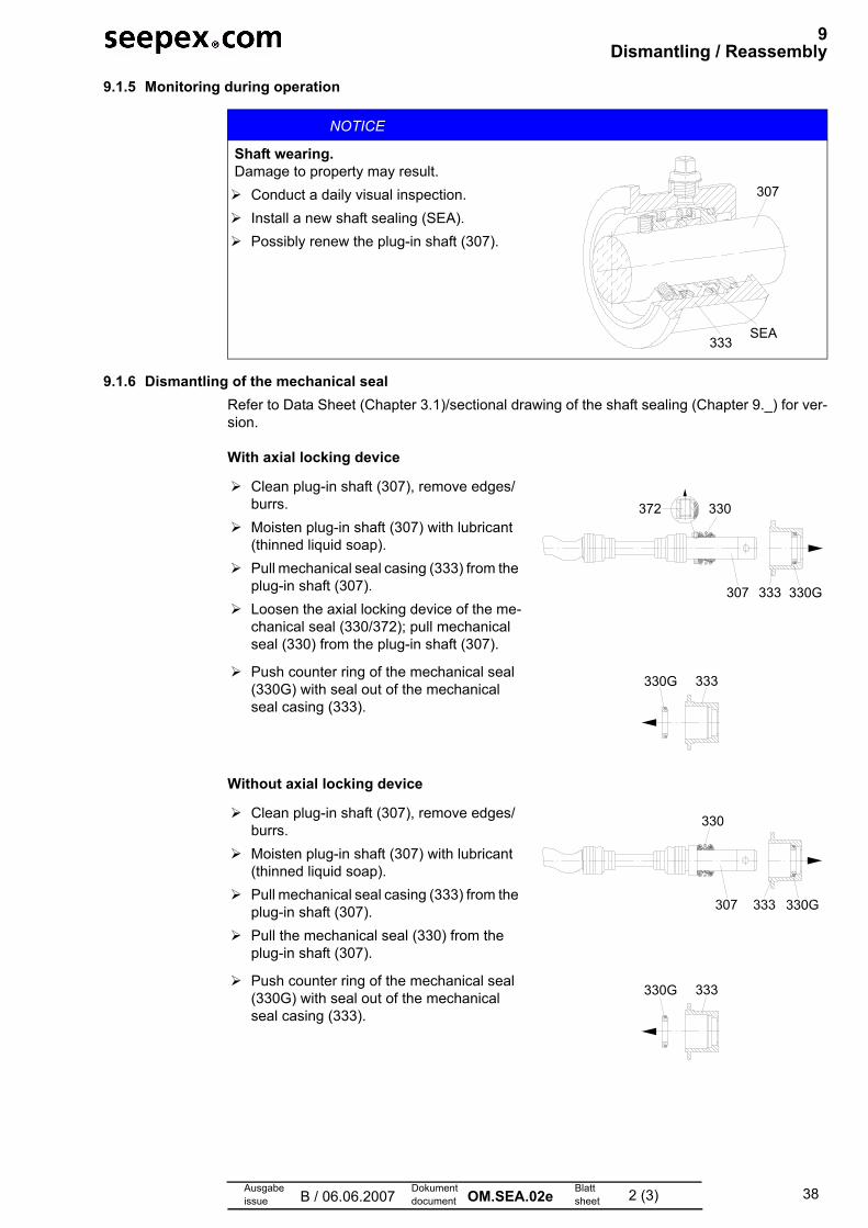
38
9 Dismantling / Reassembly
Ausgabeissue B / 06.06.2007
Dokumentdocument OM.SEA.02e Blatt
sheet 2 (3)
9.1.5 Monitoring during operation
9.1.6 Dismantling of the mechanical seal Refer to Data Sheet (Chapter 3.1)/sectional drawing of the shaft sealing (Chapter 9._) for ver-sion.
With axial locking device
Without axial locking device
NOTICE
Shaft wearing.Damage to property may result.
Conduct a daily visual inspection.Install a new shaft sealing (SEA).Possibly renew the plug-in shaft (307).
307
333SEA
Clean plug-in shaft (307), remove edges/burrs.Moisten plug-in shaft (307) with lubricant (thinned liquid soap). Pull mechanical seal casing (333) from the plug-in shaft (307). Loosen the axial locking device of the me-chanical seal (330/372); pull mechanical seal (330) from the plug-in shaft (307).
Push counter ring of the mechanical seal (330G) with seal out of the mechanical seal casing (333).
Clean plug-in shaft (307), remove edges/burrs.Moisten plug-in shaft (307) with lubricant (thinned liquid soap). Pull mechanical seal casing (333) from the plug-in shaft (307). Pull the mechanical seal (330) from the plug-in shaft (307).
Push counter ring of the mechanical seal (330G) with seal out of the mechanical seal casing (333).
333 330G307
372 330
333330G
330
333330G

39
9 Dismantling / Reassembly
Ausgabeissue B / 06.06.2007
Dokumentdocument OM.SEA.02e Blatt
sheet 3 (3)
9.2 Reassembly of mechanical seal
Assembly aids such as oil/grease are not permitted.
With axial locking device
Without axial locking device
Shaft sealings are premium precision parts. Their installation is therefore to be undertaken with care.Gentle handling and the utmost of cleanliness are prerequisites.
Clean the mechanical seal casing (333). Moisten seal with lubricant (thinned liquid soap). Press counter ring and seal using even pressure into the mechanical seal casing (333).
Clean the plug-in shaft (307), remove edg-es/burrs.Adjust the set collar (372) in accordance with sectional drawing of shaft sealing (Chapter 9._). Stick the set screw on (medium torque) and anchor.Moisten plug-in shaft (307) and Elastomer parts of the mechanical seal with lubricant (thinned liquid soap).Push mechanical seal casing (333) onto the plug-in shaft (307) until the plant edge has been reached.
Clean the mechanical seal casing (333). Moisten the seal with lubricant (thinned liq-uid soap).Press the counter ring and seal using even pressure onto the mechanical seal casing (333).
Clean the plug-in shaft (307), remove edg-es/burrs. Adjust mechanical seal in accordance with sectional drawing of shaft sealing (Chapter 9._) to the plug-in shaft (307). Moisten plug-in shaft (307) and Elastomer parts with lubricant (thinned liquid soap).Slide mechanical seal onto the plug-in shaft (307) until the plant edge has been reached.
333330G
372
330G333307
330
333330G
330G
330
333307
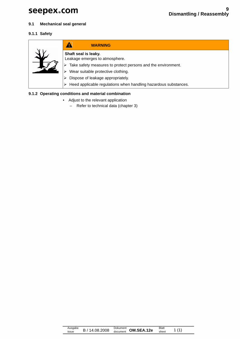
Ausgabeissue B / 14.08.2008
Dokumentdocument OM.SEA.12e Blatt
sheet 1 (1)
9 Dismantling / Reassembly
9.1 Mechanical seal general
9.1.1 Safety
9.1.2 Operating conditions and material combination• Adjust to the relevant application
– Refer to technical data (chapter 3)
WARNING
Shaft seal is leaky.Leakage emerges to atmosphere. Take safety measures to protect persons and the environment. Wear suitable protective clothing. Dispose of leakage appropriately. Heed applicable regulations when handling hazardous substances.
41Ausgabeissue A / 10.10.2005
Dokumentdocument OM.SZG.02e Blatt
sheet 1 (1)
10 Spare Parts
10.1 Version for copying
10.2 Sectional Drawing and Part List
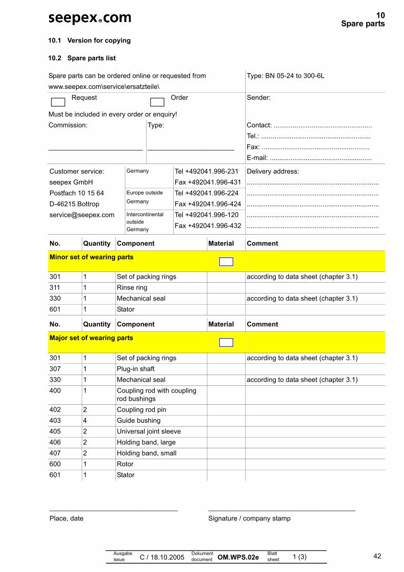
42Ausgabeissue C / 18.10.2005
Dokumentdocument OM.WPS.02e Blatt
sheet 1 (3)
10 Spare parts
10.1 Version for copying
10.2 Spare parts list
Spare parts can be ordered online or requested fromwww.seepex.com\service\ersatzteile\
Type: BN 05-24 to 300-6L
Request Order Sender:
Must be included in every order or enquiry!Commission: Type: Contact: ....................................................
Tel.: .........................................................._________________________ _______________________ Fax: .........................................................
E-mail: ......................................................
Customer service:seepex GmbHPostfach 10 15 64D-46215 [email protected]
Germany Tel +492041.996-231Fax +492041.996-431
Delivery address:..............................................................................................................................................................................................................................................................................................................................................................
Europe outsideGermany
Tel +492041.996-224Fax +492041.996-424
IntercontinentaloutsideGermany
Tel +492041.996-120Fax +492041.996-432
No. Quantity Component Material Comment
Minor set of wearing parts
301 1 Set of packing rings according to data sheet (chapter 3.1)311 1 Rinse ring330 1 Mechanical seal according to data sheet (chapter 3.1)601 1 Stator
No. Quantity Component Material Comment
Major set of wearing parts
301 1 Set of packing rings according to data sheet (chapter 3.1)307 1 Plug-in shaft330 1 Mechanical seal according to data sheet (chapter 3.1)400 1 Coupling rod with coupling
rod bushings402 2 Coupling rod pin403 4 Guide bushing405 2 Universal joint sleeve406 2 Holding band, large407 2 Holding band, small600 1 Rotor601 1 Stator
__________________________________ _______________________________________Place, date Signature / company stamp

43
10 Spare parts
Ausgabeissue C / 18.10.2005
Dokumentdocument OM.WPS.02e Blatt
sheet 2 (3)
10.3 Version for copying
No. Quantity Component Material Comment
Set of gaskets
301 1 Set of packing rings according to data sheet (chapter 3.1)310 1 Splash ring according to data sheet (chapter 3.1)330 1 Mechanical seal501 1 Casing gasket503 3 Sealing ring511 2 O-ring/cleaning cover517 2 Sealing ring706 1 Sealing ring
No. Quantity Component Material Comment
Plug-in shaft & shaft seal
301 Set of packing rings according to data sheet (chapter 3.1)307 Plug-in shaft309 Plug-in shaft pin310 Splash ring according to data sheet (chapter 3.1)330 Mechanical seal according to data sheet (chapter 3.1)
No. Quantity Component Material Comment
Coupling rod & joint parts
400 Coupling rod with coupling rod bushings
401 Retaining sleeve402 Coupling rod pin403 Guide bushing405 Universal joint sleeve406 Holding band, large407 Holding band, small401-407 Complete set of joint parts
__________________________________ _______________________________________Place, date Signature / company stamp

44
10 Spare parts
Ausgabeissue C / 18.10.2005
Dokumentdocument OM.WPS.02e Blatt
sheet 3 (3)
10.4 Version for copying
No. Quantity Component Material Comment
Pumping elements
600 Rotor601 Stator
No. Quantity Component Material Comment
Miscellaneous parts
501 Casing gasket098 Pin joint grease 1 cartridge = 300 g (approx. 315 cm³)
Grease quantity according to maintenance (chapter 7.0)
__________________________________ _______________________________________Place, date Signature / company stamp
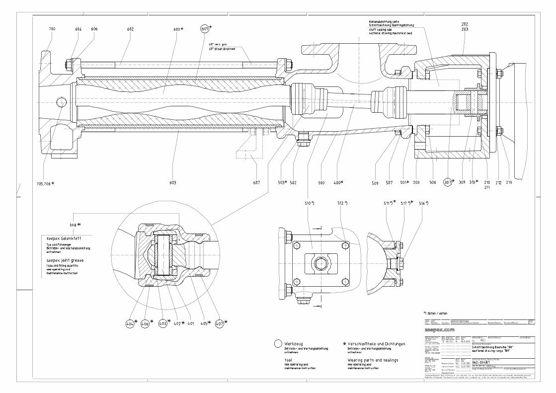
45
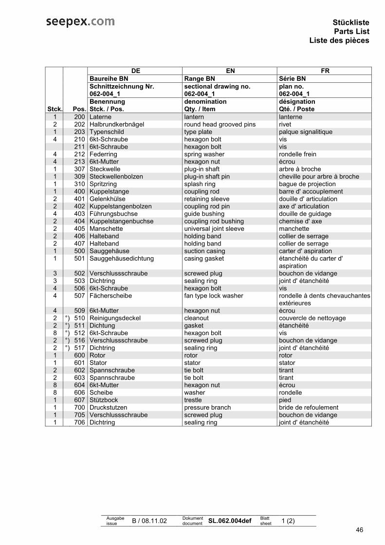
46
StücklisteParts List
Liste des pièces
Ausgabe issue B / 08.11.02 Dokument
document SL.062.004def Blatt sheet 1 (2)
DE EN FR Baureihe BN Range BN Série BN Schnittzeichnung Nr. sectional drawing no. plan no. 062-004_1 062-004_1 062-004_1 Benennung denomination désignation
Stck. Pos. Stck. / Pos. Qty. / Item Qté. / Poste 1 200 Laterne lantern lanterne 2 202 Halbrundkerbnägel round head grooved pins rivet 1 203 Typenschild type plate palque signalitique 4 210 6kt-Schraube hexagon bolt vis
211 6kt-Schraube hexagon bolt vis 4 212 Federring spring washer rondelle frein 4 213 6kt-Mutter hexagon nut écrou 1 307 Steckwelle plug-in shaft arbre à broche 1 309 Steckwellenbolzen plug-in shaft pin cheville pour arbre à broche 1 310 Spritzring splash ring bague de projection 1 400 Kuppelstange coupling rod barre d' accouplement 2 401 Gelenkhülse retaining sleeve douille d' articulation 2 402 Kuppelstangenbolzen coupling rod pin axe d' articulation 4 403 Führungsbuchse guide bushing douille de guidage 2 404 Kuppelstangenbuchse coupling rod bushing chemise d' axe 2 405 Manschette universal joint sleeve manchette 2 406 Halteband holding band collier de serrage 2 407 Halteband holding band collier de serrage 1 500 Sauggehäuse suction casing carter d' aspiration 1 501 Sauggehäusedichtung casing gasket étanchéité du carter d'
aspiration 3 502 Verschlussschraube screwed plug bouchon de vidange 3 503 Dichtring sealing ring joint d' étanchéité 4 506 6kt-Schraube hexagon bolt vis 4 507 Fächerscheibe fan type lock washer rondelle à dents chevauchantes
extérieures 4 509 6kt-Mutter hexagon nut écrou 2 °) 510 Reinigungsdeckel cleanout couvercle de nettoyage 2 °) 511 Dichtung gasket étanchéité 8 °) 512 6kt-Schraube hexagon bolt vis 2 °) 516 Verschlussschraube screwed plug bouchon de vidange 2 °) 517 Dichtring sealing ring joint d' étanchéité 1 600 Rotor rotor rotor 1 601 Stator stator stator 2 602 Spannschraube tie bolt tirant 2 603 Spannschraube tie bolt tirant 8 604 6kt-Mutter hexagon nut écrou 8 606 Scheibe washer rondelle 1 607 Stützbock trestle pied 1 700 Druckstutzen pressure branch bride de refoulement 1 705 Verschlussschraube screwed plug bouchon de vidange 1 706 Dichtring sealing ring joint d' étanchéité
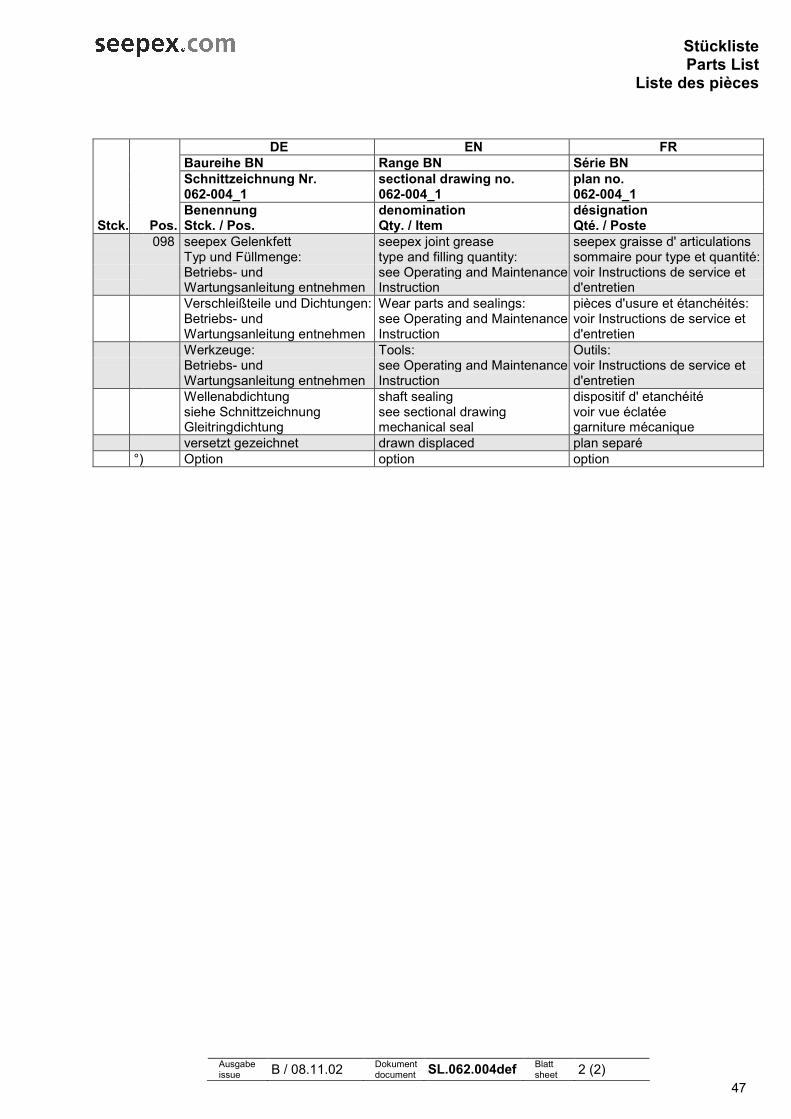
47
StücklisteParts List
Liste des pièces
Ausgabe issue B / 08.11.02 Dokument
document SL.062.004def Blatt sheet 2 (2)
DE EN FR Baureihe BN Range BN Série BN Schnittzeichnung Nr. sectional drawing no. plan no. 062-004_1 062-004_1 062-004_1 Benennung denomination désignation
Stck. Pos. Stck. / Pos. Qty. / Item Qté. / Poste 098 seepex Gelenkfett seepex joint grease seepex graisse d' articulations
Typ und Füllmenge: type and filling quantity: sommaire pour type et quantité:Betriebs- und Wartungsanleitung entnehmen
see Operating and Maintenance Instruction
voir Instructions de service et d'entretien
Verschleißteile und Dichtungen: Wear parts and sealings: pièces d'usure et étanchéités: Betriebs- und Wartungsanleitung entnehmen
see Operating and Maintenance Instruction
voir Instructions de service et d'entretien
Werkzeuge: Tools: Outils: Betriebs- und Wartungsanleitung entnehmen
see Operating and Maintenance Instruction
voir Instructions de service et d'entretien
Wellenabdichtung shaft sealing dispositif d' etanchéité siehe Schnittzeichnung Gleitringdichtung
see sectional drawing mechanical seal
voir vue éclatée garniture mécanique
versetzt gezeichnet drawn displaced plan separé °) Option option option
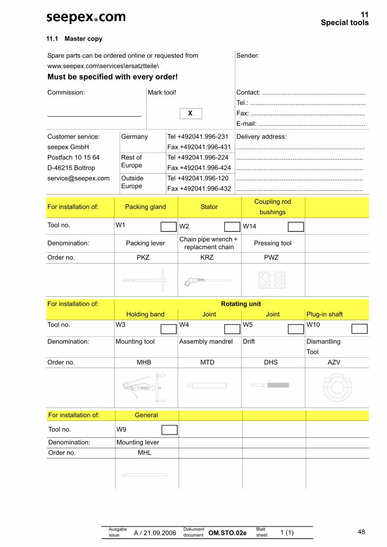
48Ausgabeissue A / 21.09.2006
Dokumentdocument OM.STO.02e Blatt
sheet 1 (1)
11 Special tools
11.1 Master copy
Spare parts can be ordered online or requested fromwww.seepex.com\services\ersatztteile\
Must be specified with every order!
Sender:
Commission: Mark tool! Contact: .........................................................Tel.: ................................................................
__________________________ X Fax: ...............................................................E-mail: ...........................................................
Customer service:seepex GmbHPostfach 10 15 64D-46215 [email protected]
Germany Tel +492041.996-231Fax +492041.996-431
Delivery address:...............................................................................................................................................................................................................................................................................................................................................................
Rest of Europe
Tel +492041.996-224Fax +492041.996-424
Outside Europe
Tel +492041.996-120Fax +492041.996-432
For installation of: Packing gland StatorCoupling rod
bushings
Tool no. W1 W2 W14
Denomination: Packing lever Chain pipe wrench + replacment chain Pressing tool
Order no. PKZ KRZ PWZ
For installation of: Rotating unitHolding band Joint Joint Plug-in shaft
Tool no. W3 W4 W5 W10
Denomination: Mounting tool Assembly mandrel Drift DismantlingTool
Order no. MHB MTD DHS AZV
For installation of: General
Tool no. W9
Denomination: Mounting leverOrder no. MHL
49Ausgabeissue A / 19.06.2008
Dokumentdocument OM.ZUG.01e Blatt
sheet 1 (1)
12Associated documents
12.1 Additional components
12.2 Technical information
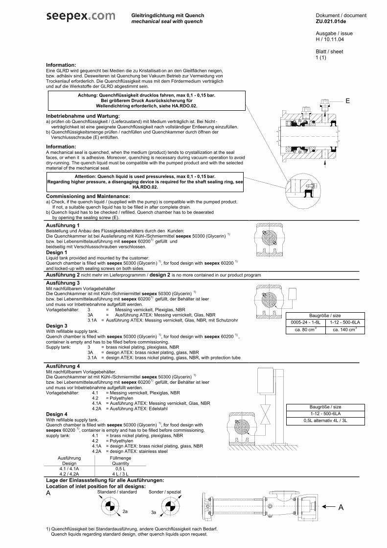
Gleitringdichtung mit Quench mechanical seal with quench
Dokument / document ZU.021.01de Ausgabe / issue H / 10.11.04 Blatt / sheet
1 (1)
Information: Eine GLRD wird gequencht bei Medien die zu Kristallisati on an den Gleitflächen neigen, bzw. adhäsiv sind. Desweiteren ist Quenchung bei Vakuum Betrieb zur Vermeidung von Trockenlauf erforderlich. Die Quenchflüssigkeit muss mit dem Fördermedium verträglich und auf die Werkstoffe der GLRD abgestimmt sein. Inbetriebnahme und Wartung: a) prüfen ob Quenchflüssigkeit / (Lieferzustand) mit Medium verträglich ist. Bei Nicht - verträglichkeit ist eine geeignete Quenchflüssigkeit nach vollständiger Entleerung einzufüllen. b) Quenchflüssigkeitsmenge prüfen / nachfüllen und Quenchkammer durch öffnen der Verschlussschraube (E) entlüften. Information: A mechanical seal is quenched, when the medium (product) tends to crystallization at the seal faces, or when it is adhesive. Moreover, quenching is necessary during vacuum-operation to avoid dry-running. The quench liquid must be compatible with the pumped product and with the selected material of the mechanical seal. Commissioning and Maintenance: a) Check, if the quench liquid / (supplied with the pump) is compatible with the pumped product. If not, a suitable quench liquid has to be filled in after complete drain. b) Quench liquid has to be checked / refilled. Quench chamber has to be deaerated by opening the sealing screw (E).
Ausführung 1 Beistellung und Anbau des Flüssigkeitsbehälters durch den Kunden: Die Quenchkammer ist bei Auslieferung mit Kühl-/Schmiermittel seepex 50300 (Glycerin) 1) bzw. bei Lebensmittelausführung mit seepex 602001) gefüllt und beidseitig mit Verschlussschrauben verschlossen. Design 1 Liquid tank provided and mounted by the customer: Quench chamber is filled with seepex 50300 (Glycerin) 1), for food design with seepex 60200 1) and locked-up with sealing screws on both sides.
Ausführung 2 nicht mehr im Lieferprogrammm / design 2 is no more contained in our product program Ausführung 3 Mit nachfüllbarem Vorlagebehälter Die Quenchkammer ist mit Kühl-/Schmiermittel seepex 50300 (Glycerin) 1) bzw. bei Lebensmittelausführung mit seepex 602001) gefüllt, der Behälter ist leer und muss vor Inbetriebnahme aufgefüllt werden. Vorlagebehälter: 3 = Messing vernickelt, Plexiglas, NBR 3A = Ausführung ATEX: Messing vernickelt, Glas, NBR 3.1A = Ausführung ATEX: Messing vernickelt, Glas, NBR, mit Schutzrohr Design 3 With refillable supply tank. Quench chamber is filled with seepex 50300 (Glycerin) 1), for food design with seepex 60200 1) , container is empty and has to be filled before commissioning. Supply tank: 3 = brass nickel plating, plexiglass, NBR 3A = design ATEX: brass nickel plating, glass, NBR 3.1A = design ATEX: brass nickel plating, glass, NBR, with protection tube
Ausführung 4 Mit nachfüllbarem Vorlagebehälter. Die Quenchkammer ist mit Kühl-/Schmiermittel seepex 50300 (Glycerin) 1) bzw. bei Lebensmittelausführung mit seepex 602001) gefüllt, der Behälter ist leer und muss vor Inbetriebnahme aufgefüllt werden. Vorlagebehälter: 4.1 = Messing vernickelt, Plexiglas, NBR 4.2 = Polyethylen 4.1A = Ausführung ATEX: Messing vernickelt, Glas, NBR 4.2A = Ausführung ATEX: Edelstahl Design 4 With refillable supply tank. Quench chamber is filled with seepex 50300 (Glycerin) 1), for food design with seepex 60200 1), container is empty and has to be filled before commissioning. supply tank: 4.1 = brass nickel plating, plexiglass, NBR 4.2 = Polyethylen 4.1A = design ATEX: brass nickel plating, glass, NBR 4.2A = design ATEX: stainless steel
Ausführung Füllmenge Design Quantity
4.1 / 4.1A 0,5 L 4.2 / 4.2A 4 L / 3 L
Lage der Einlassstellung für alle Ausführungen: Location of inlet position for all designs: A Standard / standard
Sonder / spezial
1) Quenchflüssigkeit bei Standardausführung, andere Quenchflüssigkeit nach Bedarf. Quench liquids regarding standard design, other quench liquids upon request.
2a 3a
Achtung: Quenchflüssigkeit drucklos fahren, max 0,1 - 0,15 bar. Bei größerem Druck Ausrücksicherung für
Wellendichtring erforderlich, siehe HA.RDO.02.
Attention: Quench liquid is used pressureless, max 0,1 - 0,15 bar. Regarding higher pressure, a disengaging device is required for the shaft sealing ring, see
HA.RDO.02.
E
Baugröße / size 1-12 - 500-6LA
0,5L alternativ 4L / 3L
A
Baugröße / size 0005-24 - 1-6L 1-12 - 500-6LA
ca. 80 cm3 ca. 140 cm3
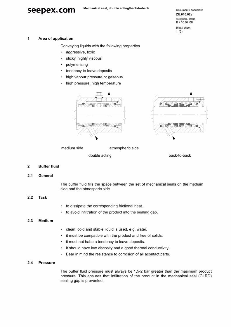
Blatt / sheet
Dokument / document
Ausgabe / issueZU.016.02e
B / 10.07.08
1 (2)
Mechanical seal, double acting/back-to-back
1 Area of application
Conveying liquids with the following properties• aggressive, toxic• sticky, highly viscous• polymerising• tendency to leave deposits• high vapour pressure or gaseous• high pressure, high temperature
2 Buffer fluid
2.1 General
The buffer fluid fills the space between the set of mechanical seals on the mediumside and the atmosperic side
2.2 Task
• to dissipate the corresponding frictional heat.• to avoid infiltration of the product into the sealing gap.
2.3 Medium
• clean, cold and stable liquid is used, e.g. water.• it must be compatible with the product and free of solids.• it must not habe a tendency to leave deposits.• it should have low viscosity and a good thermal conductivity.• Bear in mind the resistance to corrosion of all acontact parts.
2.4 Pressure
The buffer fluid pressure must always be 1,5-2 bar greater than the masimum productpressure. This ensures that infiltration of the product in the mechanical seal (GLRD)sealing gap is prevented.
medium side atmospheric side
double acting back-to-back
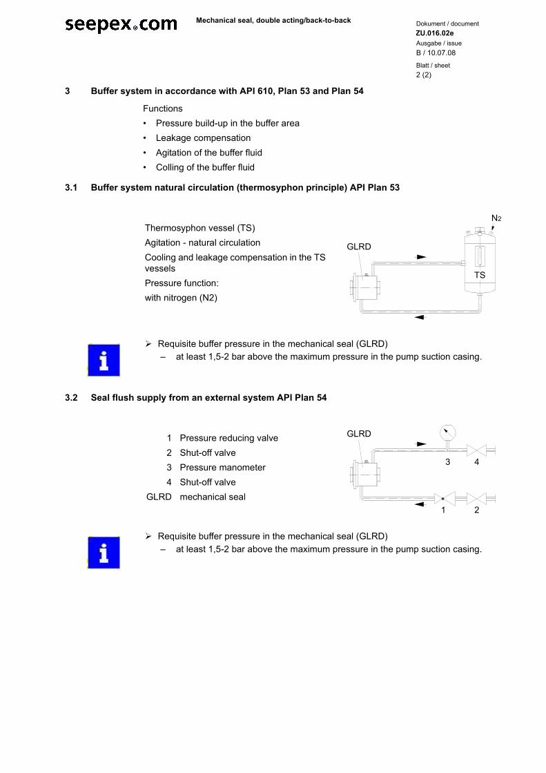
Blatt / sheet
Dokument / document
Ausgabe / issue
2 (2)
ZU.016.02e
B / 10.07.08
Mechanical seal, double acting/back-to-back
3 Buffer system in accordance with API 610, Plan 53 and Plan 54
Functions• Pressure build-up in the buffer area• Leakage compensation• Agitation of the buffer fluid• Colling of the buffer fluid
3.1 Buffer system natural circulation (thermosyphon principle) API Plan 53
3.2 Seal flush supply from an external system API Plan 54
Thermosyphon vessel (TS) Agitation - natural circulationCooling and leakage compensation in the TS vesselsPressure function:with nitrogen (N2)
GLRD
N2
TS
� Requisite buffer pressure in the mechanical seal (GLRD)– at least 1,5-2 bar above the maximum pressure in the pump suction casing.
1234
GLRD
Pressure reducing valve Shut-off valve Pressure manometer Shut-off valve mechanical seal
3 4
1 2
GLRD
� Requisite buffer pressure in the mechanical seal (GLRD)– at least 1,5-2 bar above the maximum pressure in the pump suction casing.
61Ausgabeissue A / 19.06.2008
Dokumentdocument OM.MDS.01d Blatt
sheet 1 (1)
13Appendix
13.1 Manufacturer's documents / suppliers
• available

93

Ausgabeissue A / 24.11.2008
Dokumentdocument OM.ADR.01e Blatt
sheet 1 (1)
Europe:
Great Britain Austria Belgiun Denmark
seepex UK Ltd.3 Armtech RowHoundstone Business ParkYeovil Somerset BA22 8RWTel +44.19 35.47 23 76Fax +44.19 35.47 98 [email protected]
seepex GmbHSales Office AustriaObermüllergasse 18A-3003 GablitzTel +43.22 31.6 10 85Fax +43.22 31.6 10 85 [email protected]
seepex GmbHBureau Belgie/BelgiqueIndustriezone Klein Gent-Link 21Welvaartstraat 14-1 bus 15Tel +32.14.50 14 71Fax +32.14.50 14 [email protected]
seepex Nordic ASBakkegardsvej 411DK-3050 HumlebaekTel +45.49 19 22 00Fax + 45.49 19 32 [email protected]
France Irland Italien Schweden
seepex France SARL1, Rue PelloutierF-77183 Croissy BeaubourgTel. +33.1.64 11 44 50Fax + 33.1.64 11 44 [email protected]
seepex UK Ltd.Branch Office IrelandNo 5 Arden GlasPortlaoiseCo. LaoisTel. +353.5 78 68 18 26Fax +353.5 78 68 15 [email protected]
seepex GmbHUfficio de Rappresentanza per l’ItaliaPiazza Luigi di Savolia, 2220124 MilanoTel +39.02.36 56 93 60Fax +39.02.92 87 78 [email protected]
seepex Nordic A/SHamndalsvägen 58S-61633 ÅbyTel +46.116.69 40Fax +46.116.69 41
North America:
Spain The Netherlands USA
seepex GmbHC/Copenhague, 12Edif. Tifan Oficina 20728232 La RozasMadridTel +34.91.636.13.53Fax [email protected]
seepex GmbHBureau NederlandMaagdenburgstraat 22cNL-7421 ZC DeventerTel +31.570.51.66 44Fax +31.570.51 60 [email protected]
seepex INC.5100 Speedway DriveEnon Ohio 45323Tel.+1.937.8 64 71 50Fax + 1.937.64 71 [email protected]
Asia:
China India Japan Malaysia
seepex Pumps (Shanghai) Co., Ltd.Xuanzhong Industrial Area201300 ShangheiTel +86.21.38 10 88 88Fax +86.38 10 88 [email protected]
seepex India Pvt. Ltd.Office No. 305.Raheja Arcade BuildingSector 11, C.B.D. BelapurNavi Mumbai 400614Tel +91.22.4024 0434/35Fax +91.22.4024 [email protected]
seepex Japan Co., LTD.Keyaki BuildingNakano-sakaue #101,2-31-5 Chuo, Nakano-ku,Tokyo 164-0011Tel +81.3.57 55 59 71Fax +81.3 57 55 59 [email protected]
seepex (M) Sdn. Bhd.59-1, Jalan PJU 1/37Dataran Primo47301 Petaling JayaSelengor Darul EhsanTel +60.3.78.80 69 51Fax +60.3.78 80 69 [email protected]
And what can we get flowing for you? Your nearest contact:
More seepex sales partners in Europe, America, Asia, Africa and Oceania you will find onour website. Or visit www.seepex.com
seepex GmbH Postfach 10 15 64 46215 Bottrop Scharnhölzstraße 344 46240 Bottrop Germany Tel. +49.2041.996-0 Fax +49.2041.996-400 [email protected] www.seepex.com