Embed Size (px)
Citation preview
1SLVA858–December 2016Submit Documentation Feedback
Copyright © 2016, Texas Instruments Incorporated
Operating an Engine-Grille Shutter Motor With DRV8872-Q1
Application ReportSLVA858–December 2016
Operating an Engine-Grille Shutter MotorWith DRV8872-Q1
Ishtiaque Amin, Rick Duncan
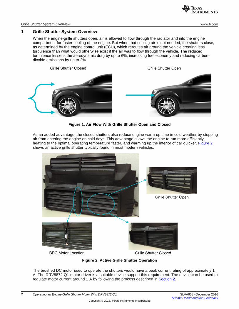
ABSTRACTThe addition of an active grille shutter is a key aerodynamic improvement in recent model-year vehicles.Depending on the ambient temperature of the environment, the shutters behind the engine grille can openand close to increase the engine efficiency and reduce turbulent air from entering the engine, therebyreducing drag. The shutters can be operated by a brushed DC (BDC) motor. A suitable device for such anapplication is Texas Instruments' DRV8872-Q1 BDC motor driver. This application report provides adetailed overview of how the DRV8872-Q1 device can be used to design a circuit to operate an engine-grille shutter motor.
Contents1 Grille Shutter System Overview ........................................................................................... 22 Internal Current Regulation With DRV8872-Q1.......................................................................... 33 Circuit Design for Grille-Shutter Application.............................................................................. 34 Grille Shutter Motor-Current Profile ....................................................................................... 5Appendix A Glossary.............................................................................................................. 7
List of Figures
1 Air Flow With Grille Shutter Open and Closed........................................................................... 22 Active Grille Shutter Operation............................................................................................. 23 Internal Current-Chopping Timing Diagram .............................................................................. 34 Typical Stall-Detection Circuit .............................................................................................. 45 Motor Phase-Voltage Profile ............................................................................................... 46 Motor-Current Profile ........................................................................................................ 57 Forward Direction Motor Stalling .......................................................................................... 58 Reverse Direction Motor Stalling .......................................................................................... 6
TrademarksAll trademarks are the property of their respective owners.
Grille Shutter System Overview www.ti.com
2 SLVA858–December 2016Submit Documentation Feedback
Copyright © 2016, Texas Instruments Incorporated
Operating an Engine-Grille Shutter Motor With DRV8872-Q1
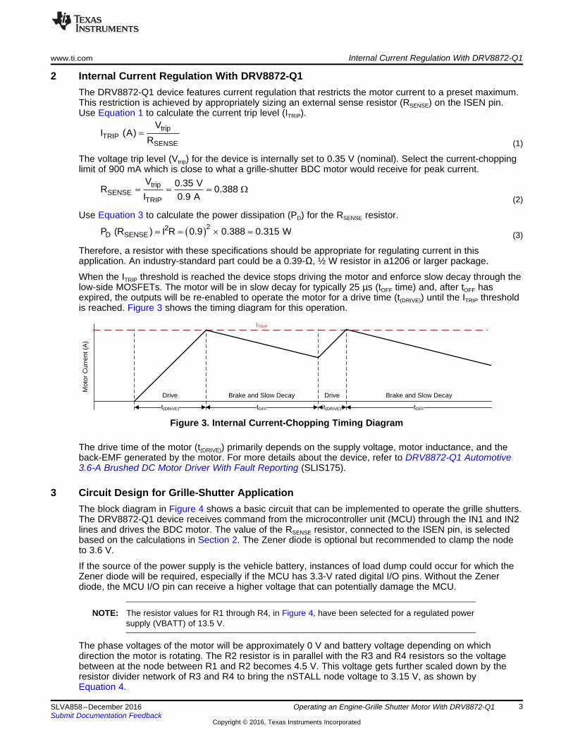
1 Grille Shutter System OverviewWhen the engine-grille shutters open, air is allowed to flow through the radiator and into the enginecompartment for faster cooling of the engine. But when that cooling air is not needed, the shutters close,as determined by the engine control unit (ECU), which reroutes air around the vehicle creating lessturbulence than what would otherwise exist if the air was to flow through the vehicle. The reducedturbulence lessens the aerodynamic drag by up to 6%, increasing fuel economy and reducing carbon-dioxide emissions by up to 2%.
Figure 1. Air Flow With Grille Shutter Open and Closed
As an added advantage, the closed shutters also reduce engine warm-up time in cold weather by stoppingair from entering the engine on cold days. This advantage allows the engine to run more efficiently,heating to the optimal operating temperature faster, and warming up the interior of car quicker. Figure 2shows an active grille shutter typically found in most modern vehicles.
Figure 2. Active Grille Shutter Operation
The brushed DC motor used to operate the shutters would have a peak current rating of approximately 1A. The DRV8872-Q1 motor driver is a suitable device support this requirement. The device can be used toregulate motor current around 1 A by following the process described in Section 2.
t(DRIVE) tOFF t(DRIVE) tOFF
Mot
or C
urre
nt (
A)
Drive Brake and Slow Decay Drive Brake and Slow Decay
ITRIP
22
D SENSEP (R ) I R 0.9 0.388 0.315 W u
tripSENSE
TRIP
V 0.35 VR 0.388
I 0.9 A :
tripTRIP
SENSE
VI (A)
R
www.ti.com Internal Current Regulation With DRV8872-Q1
3SLVA858–December 2016Submit Documentation Feedback
Copyright © 2016, Texas Instruments Incorporated
Operating an Engine-Grille Shutter Motor With DRV8872-Q1
2 Internal Current Regulation With DRV8872-Q1The DRV8872-Q1 device features current regulation that restricts the motor current to a preset maximum.This restriction is achieved by appropriately sizing an external sense resistor (RSENSE) on the ISEN pin.Use Equation 1 to calculate the current trip level (ITRIP).
(1)
The voltage trip level (Vtrip) for the device is internally set to 0.35 V (nominal). Select the current-choppinglimit of 900 mA which is close to what a grille-shutter BDC motor would receive for peak current.
(2)
Use Equation 3 to calculate the power dissipation (PD) for the RSENSE resistor.
(3)
Therefore, a resistor with these specifications should be appropriate for regulating current in thisapplication. An industry-standard part could be a 0.39-Ω, ½ W resistor in a1206 or larger package.
When the ITRIP threshold is reached the device stops driving the motor and enforce slow decay through thelow-side MOSFETs. The motor will be in slow decay for typically 25 µs (tOFF time) and, after tOFF hasexpired, the outputs will be re-enabled to operate the motor for a drive time (t(DRIVE)) until the ITRIP thresholdis reached. Figure 3 shows the timing diagram for this operation.
Figure 3. Internal Current-Chopping Timing Diagram
The drive time of the motor (t(DRIVE)) primarily depends on the supply voltage, motor inductance, and theback-EMF generated by the motor. For more details about the device, refer to DRV8872-Q1 Automotive3.6-A Brushed DC Motor Driver With Fault Reporting (SLIS175).
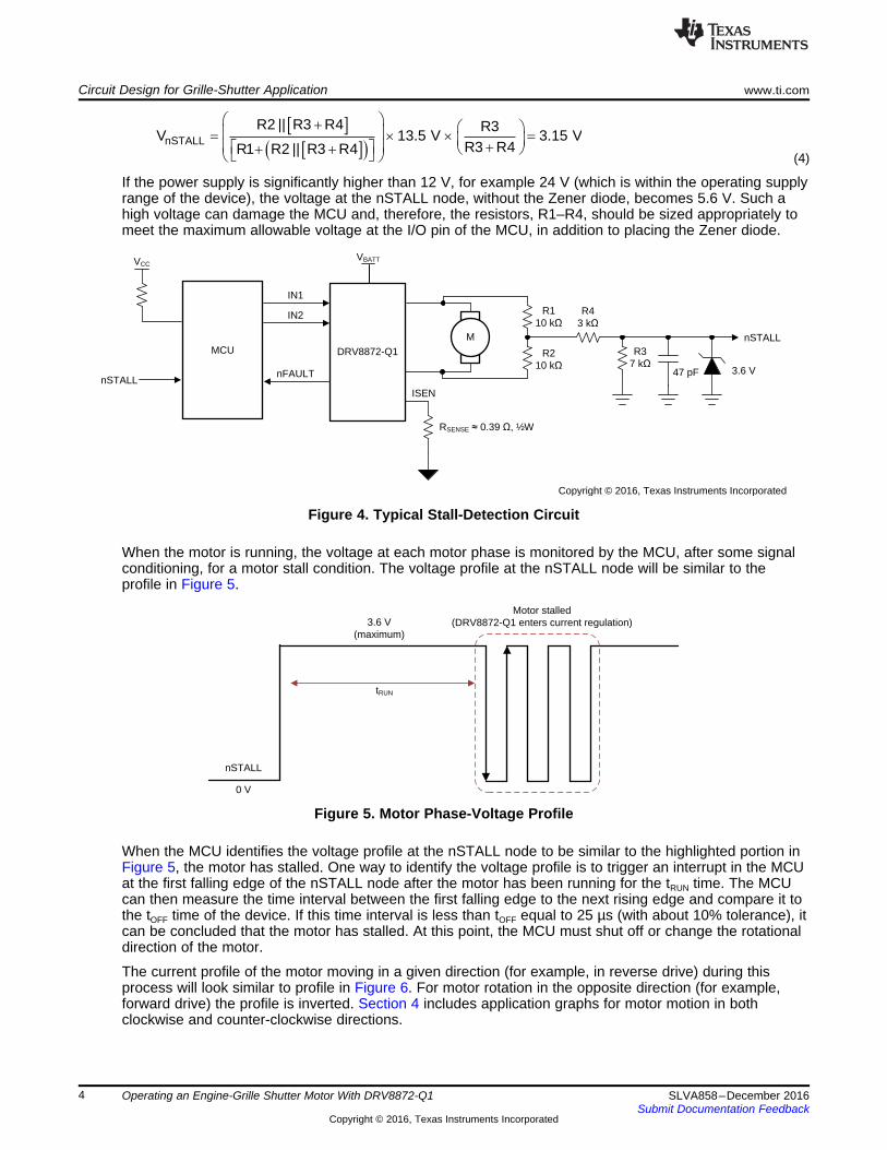
3 Circuit Design for Grille-Shutter ApplicationThe block diagram in Figure 4 shows a basic circuit that can be implemented to operate the grille shutters.The DRV8872-Q1 device receives command from the microcontroller unit (MCU) through the IN1 and IN2lines and drives the BDC motor. The value of the RSENSE resistor, connected to the ISEN pin, is selectedbased on the calculations in Section 2. The Zener diode is optional but recommended to clamp the nodeto 3.6 V.
If the source of the power supply is the vehicle battery, instances of load dump could occur for which theZener diode will be required, especially if the MCU has 3.3-V rated digital I/O pins. Without the Zenerdiode, the MCU I/O pin can receive a higher voltage that can potentially damage the MCU.
NOTE: The resistor values for R1 through R4, in Figure 4, have been selected for a regulated powersupply (VBATT) of 13.5 V.
The phase voltages of the motor will be approximately 0 V and battery voltage depending on whichdirection the motor is rotating. The R2 resistor is in parallel with the R3 and R4 resistors so the voltagebetween at the node between R1 and R2 becomes 4.5 V. This voltage gets further scaled down by theresistor divider network of R3 and R4 to bring the nSTALL node voltage to 3.15 V, as shown byEquation 4.
nSTALL
tRUN
0 V
3.6 V (maximum)
Motor stalled(DRV8872-Q1 enters current regulation)
MCU DRV8872-Q1
M
RSENSE §0.39 , ½W
R210 k
R110 k
R37 k
R43 k
nSTALL
VCC
IN1
IN2
nFAULT
ISEN
nSTALL
Copyright © 2016, Texas Instruments Incorporated
3.6 V
VBATT
47 pF
> @> @ nSTALL
R2 || R3 R4 R3V 13.5 V 3.15 V
R3 R4R1 R2 || R3 R4
§ · § ·¨ ¸ u u ¨ ¸¨ ¸ ª º © ¹¬ ¼© ¹
Circuit Design for Grille-Shutter Application www.ti.com
4 SLVA858–December 2016Submit Documentation Feedback
Copyright © 2016, Texas Instruments Incorporated
Operating an Engine-Grille Shutter Motor With DRV8872-Q1
(4)
If the power supply is significantly higher than 12 V, for example 24 V (which is within the operating supplyrange of the device), the voltage at the nSTALL node, without the Zener diode, becomes 5.6 V. Such ahigh voltage can damage the MCU and, therefore, the resistors, R1–R4, should be sized appropriately tomeet the maximum allowable voltage at the I/O pin of the MCU, in addition to placing the Zener diode.
Figure 4. Typical Stall-Detection Circuit
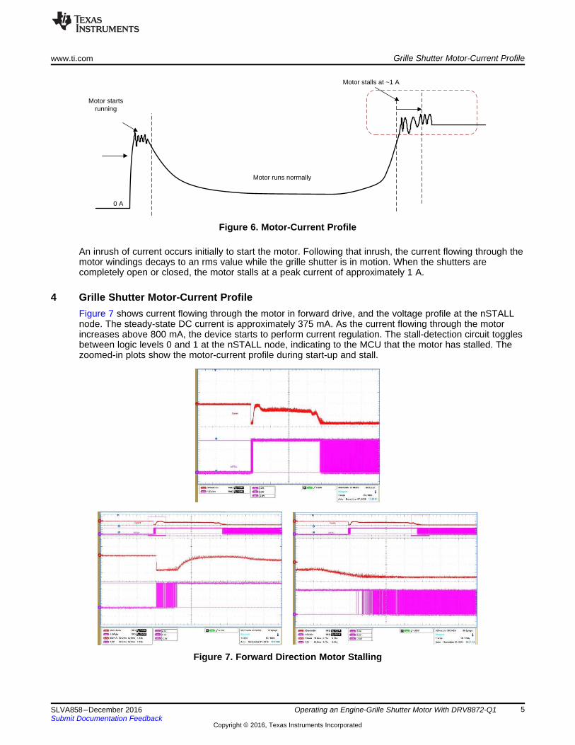
When the motor is running, the voltage at each motor phase is monitored by the MCU, after some signalconditioning, for a motor stall condition. The voltage profile at the nSTALL node will be similar to theprofile in Figure 5.
Figure 5. Motor Phase-Voltage Profile
When the MCU identifies the voltage profile at the nSTALL node to be similar to the highlighted portion inFigure 5, the motor has stalled. One way to identify the voltage profile is to trigger an interrupt in the MCUat the first falling edge of the nSTALL node after the motor has been running for the tRUN time. The MCUcan then measure the time interval between the first falling edge to the next rising edge and compare it tothe tOFF time of the device. If this time interval is less than tOFF equal to 25 µs (with about 10% tolerance), itcan be concluded that the motor has stalled. At this point, the MCU must shut off or change the rotationaldirection of the motor.
The current profile of the motor moving in a given direction (for example, in reverse drive) during thisprocess will look similar to profile in Figure 6. For motor rotation in the opposite direction (for example,forward drive) the profile is inverted. Section 4 includes application graphs for motor motion in bothclockwise and counter-clockwise directions.
0 A
Motor starts running
Motor stalls at ~1 A
Motor runs normally
www.ti.com Grille Shutter Motor-Current Profile
5SLVA858–December 2016Submit Documentation Feedback
Copyright © 2016, Texas Instruments Incorporated
Operating an Engine-Grille Shutter Motor With DRV8872-Q1
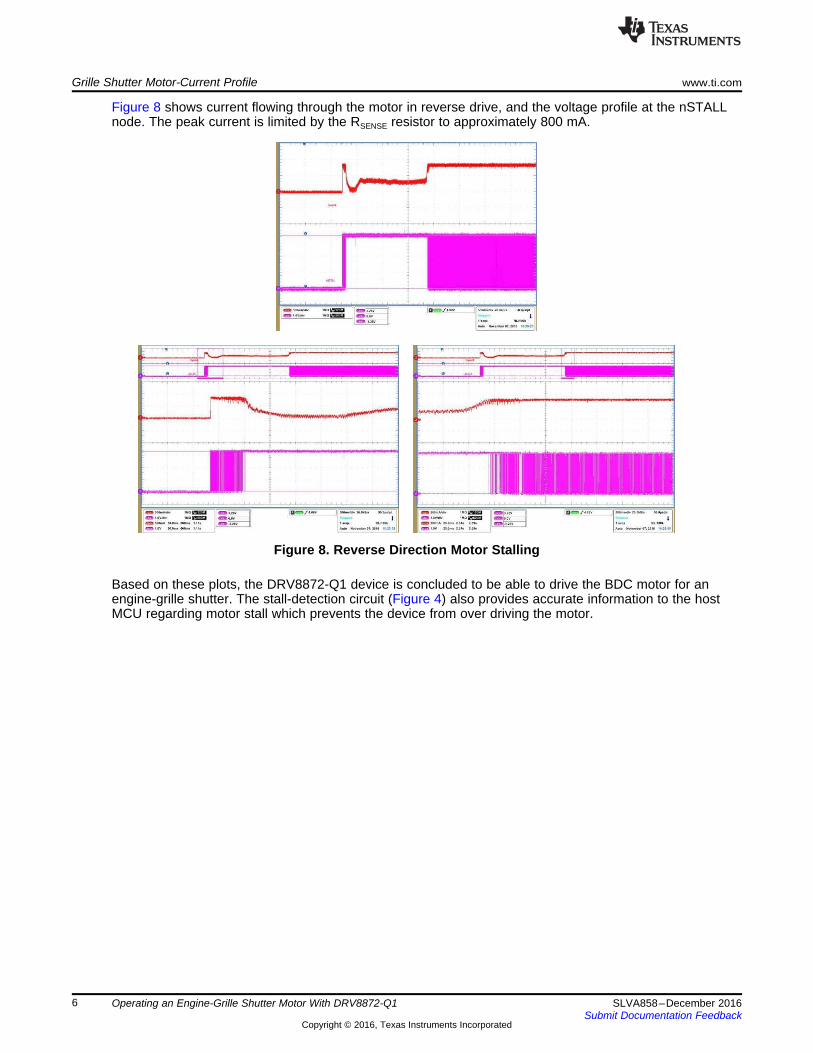
Figure 6. Motor-Current Profile
An inrush of current occurs initially to start the motor. Following that inrush, the current flowing through themotor windings decays to an rms value while the grille shutter is in motion. When the shutters arecompletely open or closed, the motor stalls at a peak current of approximately 1 A.
4 Grille Shutter Motor-Current ProfileFigure 7 shows current flowing through the motor in forward drive, and the voltage profile at the nSTALLnode. The steady-state DC current is approximately 375 mA. As the current flowing through the motorincreases above 800 mA, the device starts to perform current regulation. The stall-detection circuit togglesbetween logic levels 0 and 1 at the nSTALL node, indicating to the MCU that the motor has stalled. Thezoomed-in plots show the motor-current profile during start-up and stall.
Figure 7. Forward Direction Motor Stalling
Grille Shutter Motor-Current Profile www.ti.com
6 SLVA858–December 2016Submit Documentation Feedback
Copyright © 2016, Texas Instruments Incorporated
Operating an Engine-Grille Shutter Motor With DRV8872-Q1
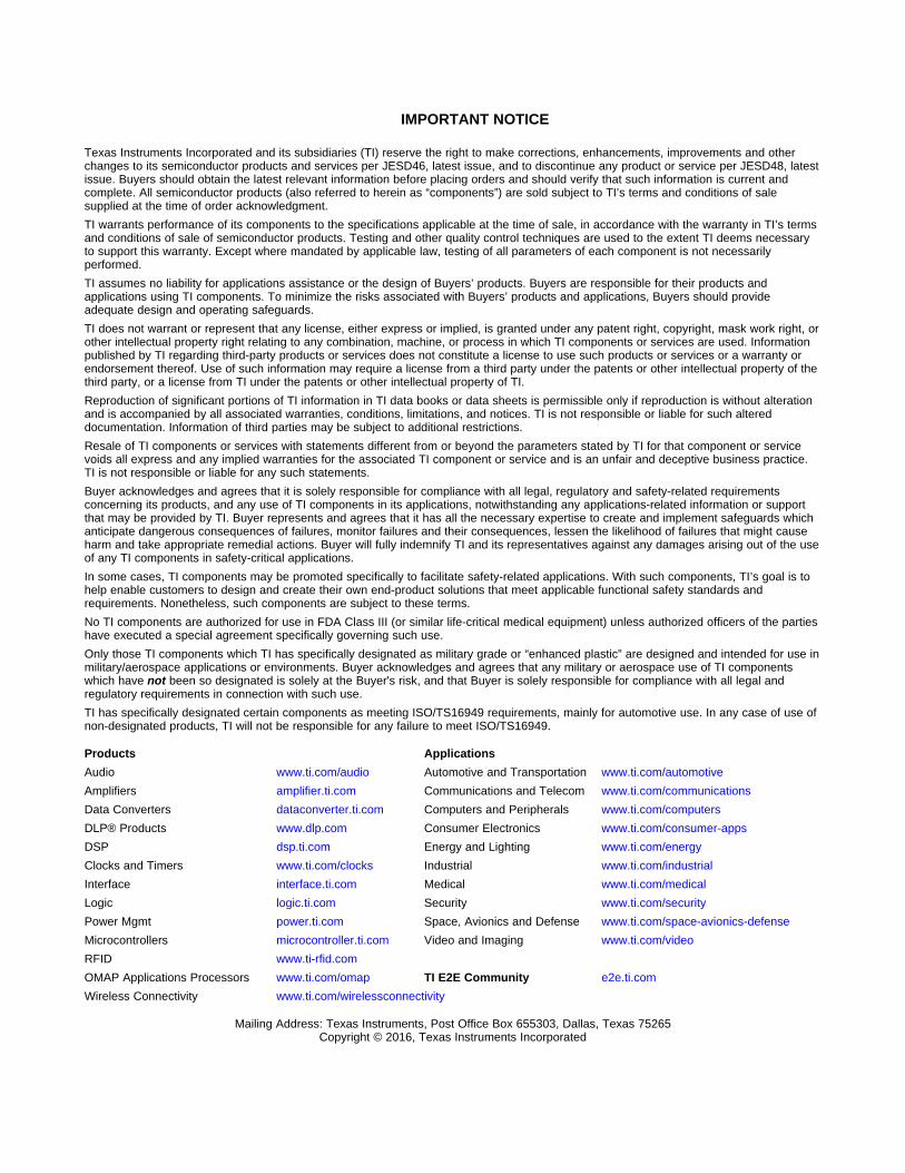
Figure 8 shows current flowing through the motor in reverse drive, and the voltage profile at the nSTALLnode. The peak current is limited by the RSENSE resistor to approximately 800 mA.
Figure 8. Reverse Direction Motor Stalling
Based on these plots, the DRV8872-Q1 device is concluded to be able to drive the BDC motor for anengine-grille shutter. The stall-detection circuit (Figure 4) also provides accurate information to the hostMCU regarding motor stall which prevents the device from over driving the motor.

7SLVA858–December 2016Submit Documentation Feedback
Copyright © 2016, Texas Instruments Incorporated
Operating an Engine-Grille Shutter Motor With DRV8872-Q1
Appendix ASLVA858–December 2016
Glossary
A.1 Nomenclature Used in this DocumentThe following acronyms and initialisms are used in ths document:
BDC — Brushed DC
ECU — Engine control unit
IC — Integrated circuit
MCU — Microcontroller unit
MOSFET — Metal-oxide semiconductor field-effect transistor
OCP — Overcurrent protection
PWM— Pulse width modulation
For a more comprehensive list of terms, acronyms, and definitions, refer to the TI Glossary (SLYZ022).
IMPORTANT NOTICE
Texas Instruments Incorporated and its subsidiaries (TI) reserve the right to make corrections, enhancements, improvements and otherchanges to its semiconductor products and services per JESD46, latest issue, and to discontinue any product or service per JESD48, latestissue. Buyers should obtain the latest relevant information before placing orders and should verify that such information is current andcomplete. All semiconductor products (also referred to herein as “components”) are sold subject to TI’s terms and conditions of salesupplied at the time of order acknowledgment.TI warrants performance of its components to the specifications applicable at the time of sale, in accordance with the warranty in TI’s termsand conditions of sale of semiconductor products. Testing and other quality control techniques are used to the extent TI deems necessaryto support this warranty. Except where mandated by applicable law, testing of all parameters of each component is not necessarilyperformed.TI assumes no liability for applications assistance or the design of Buyers’ products. Buyers are responsible for their products andapplications using TI components. To minimize the risks associated with Buyers’ products and applications, Buyers should provideadequate design and operating safeguards.TI does not warrant or represent that any license, either express or implied, is granted under any patent right, copyright, mask work right, orother intellectual property right relating to any combination, machine, or process in which TI components or services are used. Informationpublished by TI regarding third-party products or services does not constitute a license to use such products or services or a warranty orendorsement thereof. Use of such information may require a license from a third party under the patents or other intellectual property of thethird party, or a license from TI under the patents or other intellectual property of TI.Reproduction of significant portions of TI information in TI data books or data sheets is permissible only if reproduction is without alterationand is accompanied by all associated warranties, conditions, limitations, and notices. TI is not responsible or liable for such altereddocumentation. Information of third parties may be subject to additional restrictions.Resale of TI components or services with statements different from or beyond the parameters stated by TI for that component or servicevoids all express and any implied warranties for the associated TI component or service and is an unfair and deceptive business practice.TI is not responsible or liable for any such statements.Buyer acknowledges and agrees that it is solely responsible for compliance with all legal, regulatory and safety-related requirementsconcerning its products, and any use of TI components in its applications, notwithstanding any applications-related information or supportthat may be provided by TI. Buyer represents and agrees that it has all the necessary expertise to create and implement safeguards whichanticipate dangerous consequences of failures, monitor failures and their consequences, lessen the likelihood of failures that might causeharm and take appropriate remedial actions. Buyer will fully indemnify TI and its representatives against any damages arising out of the useof any TI components in safety-critical applications.In some cases, TI components may be promoted specifically to facilitate safety-related applications. With such components, TI’s goal is tohelp enable customers to design and create their own end-product solutions that meet applicable functional safety standards andrequirements. Nonetheless, such components are subject to these terms.No TI components are authorized for use in FDA Class III (or similar life-critical medical equipment) unless authorized officers of the partieshave executed a special agreement specifically governing such use.Only those TI components which TI has specifically designated as military grade or “enhanced plastic” are designed and intended for use inmilitary/aerospace applications or environments. Buyer acknowledges and agrees that any military or aerospace use of TI componentswhich have not been so designated is solely at the Buyer's risk, and that Buyer is solely responsible for compliance with all legal andregulatory requirements in connection with such use.TI has specifically designated certain components as meeting ISO/TS16949 requirements, mainly for automotive use. In any case of use ofnon-designated products, TI will not be responsible for any failure to meet ISO/TS16949.
Products ApplicationsAudio www.ti.com/audio Automotive and Transportation www.ti.com/automotiveAmplifiers amplifier.ti.com Communications and Telecom www.ti.com/communicationsData Converters dataconverter.ti.com Computers and Peripherals www.ti.com/computersDLP® Products www.dlp.com Consumer Electronics www.ti.com/consumer-appsDSP dsp.ti.com Energy and Lighting www.ti.com/energyClocks and Timers www.ti.com/clocks Industrial www.ti.com/industrialInterface interface.ti.com Medical www.ti.com/medicalLogic logic.ti.com Security www.ti.com/securityPower Mgmt power.ti.com Space, Avionics and Defense www.ti.com/space-avionics-defenseMicrocontrollers microcontroller.ti.com Video and Imaging www.ti.com/videoRFID www.ti-rfid.comOMAP Applications Processors www.ti.com/omap TI E2E Community e2e.ti.comWireless Connectivity www.ti.com/wirelessconnectivity
Mailing Address: Texas Instruments, Post Office Box 655303, Dallas, Texas 75265Copyright © 2016, Texas Instruments Incorporated