Embed Size (px)
Citation preview

OpenStack® and Cumulus® Linux
®
Validated Design Guide
Deploying OpenStack with Network Switches Running Cumulus® Linux®

OPENSTACK AND CUMULUS LINUX: VALIDATED DESIGN GUIDE
2
Contents
Contents ........................................................................................................................................................................................... 2
OpenStack with Cumulus Linux....................................................................................................................................................... 5
Objective ...................................................................................................................................................................................... 5
Enabling Choice of Hardware in the Data Center ...................................................................................................................... 5
Combined Solution Using OpenStack and Cumulus Linux ........................................................................................................ 5
Driving Towards Operational Efficiencies ................................................................................................................................... 6
Intended Audience for Network Design and Build ..................................................................................................................... 7
OpenStack Network Architecture in a PoC or Small Test/Dev Environment ................................................................................ 7
Network Architecture and Design Considerations ..................................................................................................................... 7
OpenStack Network Architecture in a Cloud Data Center ............................................................................................................. 9
Network Architecture ................................................................................................................................................................... 9
Scaling Out ................................................................................................................................................................................. 10
Out-of-Band Management ............................................................................................................................................................. 11
Building an OpenStack Cloud with Cumulus Linux ...................................................................................................................... 12
Minimum Hardware Requirements ........................................................................................................................................... 12
Network Assumptions and Numbering ..................................................................................................................................... 13
Build Steps ................................................................................................................................................................................. 17
1. Set Up Physical Network ....................................................................................................................................................... 18
2. Basic Physical Network Configuration .................................................................................................................................. 18
3. Verify Connectivity ................................................................................................................................................................. 21
4. Set Up Physical Servers ........................................................................................................................................................ 21
5. Configure Spine Switches ..................................................................................................................................................... 22
6. Configure Each Pair of Leaf Switches ................................................................................................................................... 25
7. Configure Host Devices ......................................................................................................................................................... 28
8. Install and Configure OpenStack Services ........................................................................................................................... 31
Add the Identity Service .........................................................................................................................................................31
Add the Image Service ...........................................................................................................................................................31
Add the Compute Service ......................................................................................................................................................31
Add the Networking Service ..................................................................................................................................................32
Install and Configure the Compute Node .............................................................................................................................33
9. Create Project Networks ....................................................................................................................................................... 34
Launch an Instance ...............................................................................................................................................................34
Create Virtual Networks .........................................................................................................................................................34

CONTENTS
www.cumulusnetworks.com 3
Create the Public Provider Network ......................................................................................................................................34
Private Project Networks .......................................................................................................................................................35
10. Creating VMs on OpenStack ............................................................................................................................................... 36
Launch an Instance on the Public Network ..........................................................................................................................36
Launch an Instance on the Private Network ........................................................................................................................36
Launch an Instance from Horizon .........................................................................................................................................36
Conclusion ...................................................................................................................................................................................... 37
Summary .................................................................................................................................................................................... 37
References ................................................................................................................................................................................. 37
Appendix A: Example /etc/network/interfaces Configurations ................................................................................................... 39
leaf01 ......................................................................................................................................................................................... 39
leaf02 ......................................................................................................................................................................................... 42
leaf03 ......................................................................................................................................................................................... 45
leaf04 ......................................................................................................................................................................................... 47
spine01 ...................................................................................................................................................................................... 49
spine02 ...................................................................................................................................................................................... 51
Appendix B: Network Setup Checklist ........................................................................................................................................... 53
Appendix C: Neutron Under the Hood ........................................................................................................................................... 56
Neutron Bridges ......................................................................................................................................................................... 56
Agents and Namespaces........................................................................................................................................................... 56
Neutron Routers (L3 Agents) .................................................................................................................................................57
Neutron DHCP Agent..............................................................................................................................................................57
Compute Hosts .......................................................................................................................................................................... 59

OPENSTACK AND CUMULUS LINUX: VALIDATED DESIGN GUIDE
4
Version 1.1.5
February 3, 2016
About Cumulus Networks
Unleash the power of Open Networking with Cumulus Networks. Founded by veteran networking engineers from Cisco and
VMware, Cumulus Networks makes the first Linux operating system for networking hardware and fills a critical gap in
realizing the true promise of the software-defined data center. Just as Linux completely transformed the economics and
innovation on the server side of the data center, Cumulus Linux is doing the same for the network. It is radically reducing
the costs and complexities of operating modern data center networks for service providers and businesses of all sizes.
Cumulus Networks has received venture funding from Andreessen Horowitz, Battery Ventures, Sequoia Capital, Peter
Wagner and four of the original VMware founders. For more information visit cumulusnetworks.com or @cumulusnetworks.
©2016 Cumulus Networks. CUMULUS, the Cumulus Logo, CUMULUS NETWORKS, and the Rocket Turtle Logo (the “Marks”) are trademarks and service marks
of Cumulus Networks, Inc. in the U.S. and other countries. You are not permitted to use the Marks without the prior written consent of Cumulus Networks. The
registered trademark Linux® is used pursuant to a sublicense from LMI, the exclusive licensee of Linus Torvalds, owner of the mark on a world-wide basis. All
other marks are used under fair use or license from their respective owners.
The OpenStack® Word Mark and OpenStack Logo are either registered trademarks/service marks or trademarks/service marks of the OpenStack Foundation,
in the United States and other countries and are used with the OpenStack Foundation's permission. We are not affiliated with, endorsed or sponsored by the
OpenStack Foundation, or the OpenStack community.

OPENSTACK WITH CUMULUS LINUX
www.cumulusnetworks.com 5
OpenStack with Cumulus Linux
Objective
This Validated Design Guide presents a design and implementation approach for deploying OpenStack with network
switches running Cumulus Linux. Detailed steps are included for installing and configuring both switches and servers.
Enabling Choice of Hardware in the Data Center
Cloud-oriented infrastructure designs revolutionized how server applications are delivered in the data center. They reduce
CapEx costs by commoditizing server hardware platforms and OpEx costs by automating and orchestrating infrastructure
deployment and management.
The same benefits of choice of commodity hardware and automation are available to networking in the data center. With
Cumulus Linux, network administrators now have a multi-platform network OS that provides freedom of choice with
network switch hardware. Because Cumulus Linux is Linux, data center administrators have access to a rich ecosystem of
existing Linux automation tools and now the ability for converged deployment, administration, and monitoring of compute
servers and network switches.
OpenStack is a cloud platform for enterprise and commercial IT environments. Widely deployed in private and public cloud
applications, OpenStack offers a rich variety of components that can be combined to build a tailored cloud solution.
OpenStack enables data center architects to use commodity server hardware to build infrastructure environments that
deliver the agility and easy scaling promised by the cloud. The cloud allows infrastructure consumers to request and utilize
capacity in seconds rather than hours or days, providing you with radical CapEx and OpEx savings while delivering rapid,
self-service deployment of capacity for IT consumers.
Cumulus Networks believes the same design principles should hold true for networking. A network device can be
configured at first boot, so an administrator can quickly replace failed equipment instead of spending valuable time and
resources troubleshooting hardware. This enables new support models to be leveraged to drive down operational costs.
Imagine managing your own set of hot spare switches, guaranteeing that a replacement will always be available instead of
paying for ongoing support for every device. This is the same model currently used by most organizations for managing
large fleets of servers.
Additionally, Cumulus Linux can help you achieve the same CapEx and OpEx efficiencies for your networks by enabling an
open market approach for switching platforms, and by offering a radically simple automated lifecycle management
framework built on the industry’s best open source tools. By using bare metal servers and network switches, you can
achieve cost savings that would be impossible just a few years ago.
Combined Solution Using OpenStack and Cumulus Linux
Both Cumulus Linux and Linux/OpenStack are software solutions run on top of bare metal hardware. Because both
solutions are hardware-agnostic, customers can select their chosen platform from a wide array of suppliers who often
employ highly competitive pricing models. The software defines the performance and behavior of the environment and
allows the administrator to exercise version control and programmatic approaches that are already in use by DevOps
teams.
Refer to the Cumulus Linux Hardware Compatibility List (HCL) at cumulusnetworks.com/hcl for a list of hardware vendors
and their supported model numbers, descriptions, switch silicon, and CPU type.

OPENSTACK AND CUMULUS LINUX: VALIDATED DESIGN GUIDE
6
Figure 1. OpenStack and Cumulus Linux
Driving Towards Operational Efficiencies
OpenStack enables the building of cloud environments using commodity off-the-shelf servers combined with standard Linux
virtualization, monitoring, and management technologies. Cloud users can request resources (compute VMs, storage,
network) using APIs and self-service Web interfaces, and those resources will be allocated and delivered without human
intervention. The hardware in the cloud is thus homogenous, and users neither know nor care where their resources are
physically allocated. Operators monitor aggregate resource utilization, so management is done at the level of a capacity
planning exercise, rather than worrying about individual workloads and users.
OpenStack comprises a number of components that work together to deliver a cloud. The major components are:
1. Nova, which manages compute resources for VMs.
2. Glance, which manages OS disk images.
3. Cinder, which manages VM block storage.
4. Swift, which manages unstructured data objects.
5. Keystone, which provides authentication and authorization services.
6. Horizon, a Web-based UI.
7. Neutron, which provides virtual networking and services.
Cumulus Linux complements OpenStack by delivering the same automated, self-service operational model to the network.
And since the underlying operating system is the same on the OpenStack nodes and the switches, the same automation,
monitoring and management tools can be used, greatly simplifying provisioning and operations.
Cumulus Linux offers powerful automation capabilities, by way of technologies such as ONIE, zero touch provisioning,
Ansible, Chef, Puppet, and many others. The combination of bare metal hardware with a consistent Linux platform enables
you to leverage automation to deploy servers and networks together. Thus, you can use a unified set of tools to automate
the installation and configuration of both switches and servers. You can use a common automation framework that uses a
simple config file to install and configure an entire pod of switches and call OpenStack to install and configure the servers,
all without any human intervention.
OPENSTACK NETWORK ARCHITECTURE IN A POC OR SMALL TEST/DEV ENVIRONMENT
www.cumulusnetworks.com 7
Intended Audience for Network Design and Build
The rest of this document is aimed at the data center architect or administrator interested in evaluating a Proof of Concept
(PoC) or deploying a production cloud using Cumulus Linux and OpenStack.
The implementer is expected to have basic knowledge of Linux commands, logging in, navigating the file system, and
editing files. Basic understanding of Layer 2 networking is assumed, such as interfaces, bonds (also known as LAGs), and
bridges.
If you are using this guide to help you with setting up your OpenStack and Cumulus Linux environment, we assume you
have Cumulus Linux installed and licensed on switches from the Cumulus Linux HCL. Additional information on Cumulus
Linux software, licensing, and supported hardware may be found on cumulusnetworks.com or by contacting
[email protected]. This guide references the Kilo release of OpenStack.
OpenStack Network Architecture in a PoC or
Small Test/Dev Environment
Network Architecture and Design Considerations
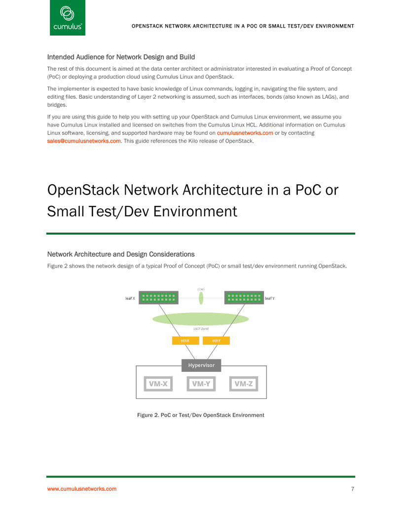
Figure 2 shows the network design of a typical Proof of Concept (PoC) or small test/dev environment running OpenStack.
Figure 2. PoC or Test/Dev OpenStack Environment

OPENSTACK AND CUMULUS LINUX: VALIDATED DESIGN GUIDE
8
Figure 3 below details the connectivity for the hypervisor.
Figure 3. Hypervisor Host Detail
The network architecture for an OpenStack PoC follows a simplified Top of Rack (ToR) access-tier-only design, all within
Layer 2, while the single services rack provides a gateway to the rest of the network, and also contains all the hypervisor
hosts. The services rack contains the OpenStack controller, and can optionally contain any load balancers, firewalls, and
other network services.
For optimal network performance, 10G switches are used for the ToR/access switches.
The network design employs multi-Chassis Link Aggregation (MLAG) for host path redundancy and link aggregation for
network traffic optimization. The switches are paired into a single logical switch for MLAG, with a peer LACP bond link
between pair members. No breakout cables are used in this design.
A single OpenStack controller instance is assumed in this design.
Connectivity to external networks is assumed to be via a pair of links to routers, with a single upstream default route. These
links are connected to the leaf switches in the services rack, since it contains the controller. This guide assumes the
routers have been configured with VRR or some other first-hop redundancy protocol. If there is only one upstream router
link, connect it to either of the leaf switches in the services rack.
The Neutron networking agents handle the creation of the bridge interface and other virtual interfaces on the compute
node. The actual naming of the bridge and vnet interfaces may be different in a live deployment.
OPENSTACK NETWORK ARCHITECTURE IN A CLOUD DATA CENTER
www.cumulusnetworks.com 9
OpenStack Network Architecture in a Cloud
Data Center
Network Architecture
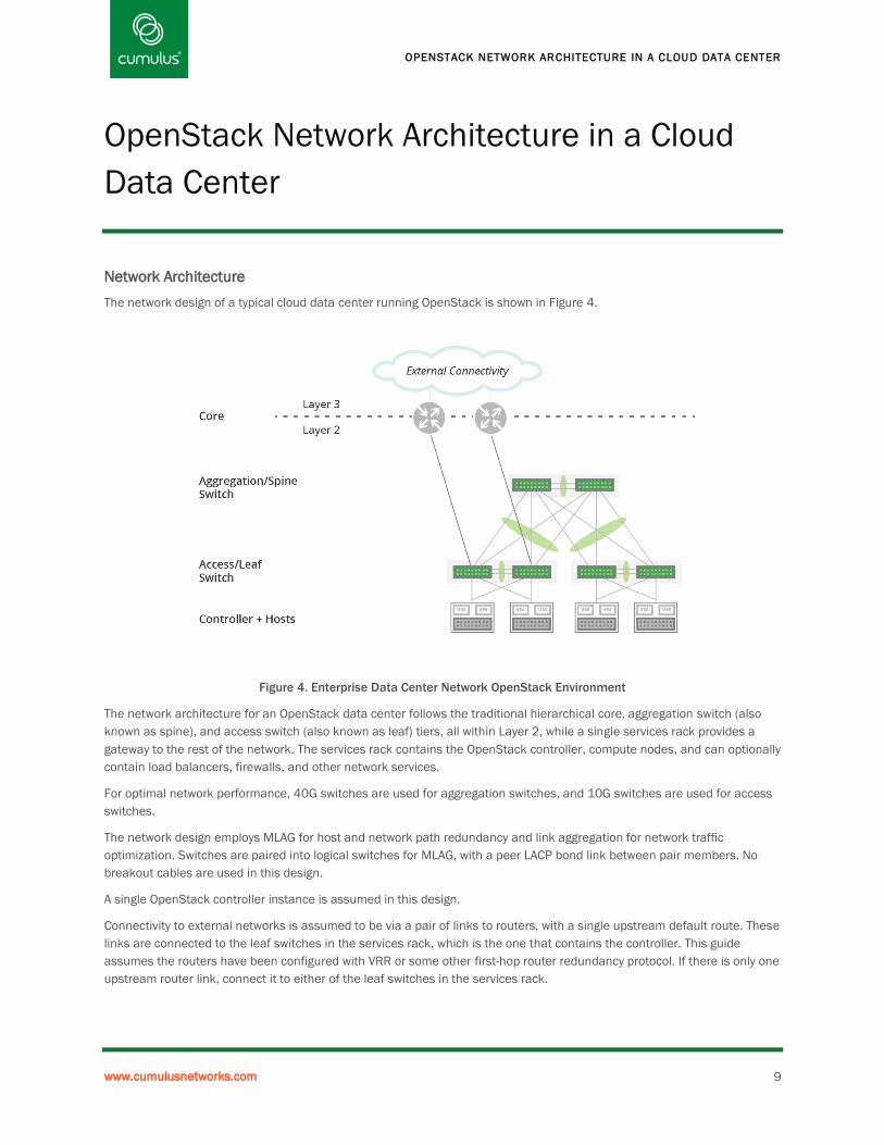
The network design of a typical cloud data center running OpenStack is shown in Figure 4.
Figure 4. Enterprise Data Center Network OpenStack Environment
The network architecture for an OpenStack data center follows the traditional hierarchical core, aggregation switch (also
known as spine), and access switch (also known as leaf) tiers, all within Layer 2, while a single services rack provides a
gateway to the rest of the network. The services rack contains the OpenStack controller, compute nodes, and can optionally
contain load balancers, firewalls, and other network services.
For optimal network performance, 40G switches are used for aggregation switches, and 10G switches are used for access
switches.
The network design employs MLAG for host and network path redundancy and link aggregation for network traffic
optimization. Switches are paired into logical switches for MLAG, with a peer LACP bond link between pair members. No
breakout cables are used in this design.
A single OpenStack controller instance is assumed in this design.
Connectivity to external networks is assumed to be via a pair of links to routers, with a single upstream default route. These
links are connected to the leaf switches in the services rack, which is the one that contains the controller. This guide
assumes the routers have been configured with VRR or some other first-hop router redundancy protocol. If there is only one
upstream router link, connect it to either of the leaf switches in the services rack.

OPENSTACK AND CUMULUS LINUX: VALIDATED DESIGN GUIDE
10
Scaling Out
Scaling out the architecture involves adding more hosts to the access switch pairs, and then adding more access switches
in pairs as needed, as shown in Figure 5.
Figure 5. Adding Additional Switches
Once the limit for the aggregation switch pair has been reached, an additional network pod of aggregation/access switch
tiers may be added, as shown in Figure 6. Each new pod has its own services rack and OpenStack controller.
Figure 6. Adding Network Pods/OpenStack Clusters

OUT-OF-BAND MANAGEMENT
www.cumulusnetworks.com 11
Out-of-Band Management
An important supplement to the high capacity production data network is the management network used to administer
infrastructure elements, such as network switches, physical servers, and storage systems. The architecture of these
networks vary considerably based on their intended use, the elements themselves, and access isolation requirements.
This solution guide assumes that a single Layer 2 domain is used to administer the network switches and management
interfaces on the controller and hypervisor hosts. These operations include installing the elements, configuring them, and
monitoring the running system. This network is expected to host both DHCP and HTTP servers, such as isc-dhcp and
apache2, as well as provide DNS reverse and forward resolution. In general, these networks provide some means to
connect to the corporate network, typically a connection through a router or jump host.
Figure 7 below shows the logical and, where possible, physical connections of each element as well as the services
required to realize this deployment.
Figure 7. Out-of-Band Management

OPENSTACK AND CUMULUS LINUX: VALIDATED DESIGN GUIDE
12
Building an OpenStack Cloud with Cumulus
Linux
Minimum Hardware Requirements
For PoC, test/dev:
• 3x x86 servers, each with 2x 10G NICs + 1x 1G NIC
• 2x 48 port 10G switches, with 40G uplinks
Note that this design may be scaled up to 47 hypervisor nodes.
For a cloud data center:
• 5x x86 servers, each with 2x 10G NICs + 1x 1G NIC
• 4x 48 port 10G leaf switches, with 40G uplinks
• 2x 32 port 40G spine switches
Note that this design may be scaled up to 1535 hypervisor nodes. If required, additional OpenStack clusters may be
configured and connected to the core/external routers. OpenStack scalability limits will be hit before full scale is achieved.

BUILDING AN OPENSTACK CLOUD WITH CUMULUS LINUX
www.cumulusnetworks.com 13
Network Assumptions and Numbering
The network design for the full cloud deployment (6 switches, 5 servers) is shown in Figure 8 below. The PoC subset is just
the first pair of leafs and no spine switches. The implementation does not assume use of IPMI, as it is intended to
demonstrate the most generic network as possible.
Figure 8. Cloud Data Center Network Topology
Note that the peer bonds for MLAG support are always the last two interfaces on each switch. For spines, they are swp31
and swp32. For leafs, they are swp51 and swp52. The next-to-last two interfaces on each leaf are for the uplinks to
spine01 and spine02.
Also note that the same subnet is used for every MLAG peer pair. This is safe because the addresses are only used on the
link between the pairs. Routing protocols will not distribute these routes because they are part of the link-local
169.254.0.0/16 subnet.
The details for the switches, hosts, and logical interfaces are as follows:
OPENSTACK AND CUMULUS LINUX: VALIDATED DESIGN GUIDE
14
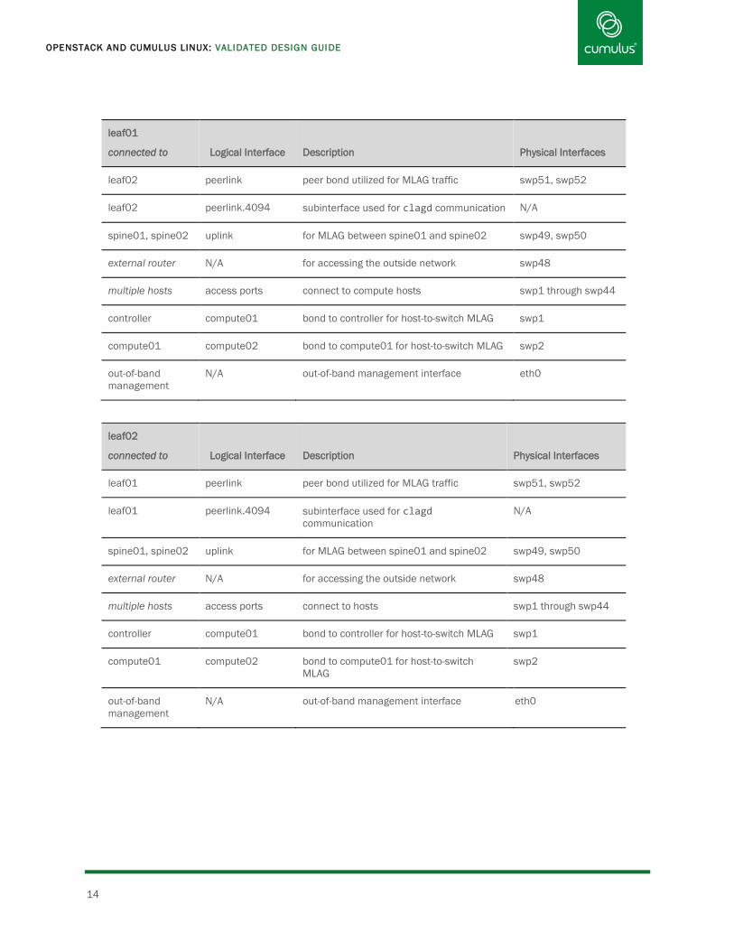
leaf01
connected to
Logical Interface
Description
Physical Interfaces
leaf02 peerlink peer bond utilized for MLAG traffic swp51, swp52
leaf02 peerlink.4094 subinterface used for clagd communication N/A
spine01, spine02 uplink for MLAG between spine01 and spine02 swp49, swp50
external router N/A for accessing the outside network swp48
multiple hosts access ports connect to compute hosts swp1 through swp44
controller compute01 bond to controller for host-to-switch MLAG swp1
compute01 compute02 bond to compute01 for host-to-switch MLAG swp2
out-of-band
management
N/A out-of-band management interface eth0
leaf02
connected to
Logical Interface
Description
Physical Interfaces
leaf01 peerlink peer bond utilized for MLAG traffic swp51, swp52
leaf01 peerlink.4094 subinterface used for clagd
communication
N/A
spine01, spine02 uplink for MLAG between spine01 and spine02 swp49, swp50
external router N/A for accessing the outside network swp48
multiple hosts access ports connect to hosts swp1 through swp44
controller compute01 bond to controller for host-to-switch MLAG swp1
compute01 compute02 bond to compute01 for host-to-switch
MLAG
swp2
out-of-band
management
N/A out-of-band management interface eth0

BUILDING AN OPENSTACK CLOUD WITH CUMULUS LINUX
www.cumulusnetworks.com 15
leaf0N
connected to
Logical Interface
Description
Physical Interfaces
Repeat the above configurations for each additional pair of leafs, minus the external router interfaces.
spine01
connected to
Logical Interface
Description
Physical Interfaces
spine02 peerlink peer bond utilized for MLAG traffic swp31, swp32
spine02 peerlink.4094 subinterface used for clagd communication N/A
multiple leafs leaf ports connect to leaf switch pairs swp1 through swp30
leaf01, leaf02 downlink1 bond to another leaf switch pair swp1, swp2
leaf03, leaf04 downlink2 bond to another leaf switch pair swp3, swp4
out-of-band
management
N/A out-of-band management interface eth0
spine02
connected to
Logical Interface
Description
Physical Interfaces
spine01 peerlink peer bond utilized for MLAG traffic swp31, swp32
spine01 peerlink.4094 subinterface used for clagd communication N/A
multiple leafs leaf ports connect to leaf switches swp1 through swp30
leaf01, leaf02 downlink1 bond to another peerlink group swp1, swp2
leaf03, leaf04 downlink2 bond to another peerlink group swp3, swp4
out-of-band
management
N/A out-of-band management interface eth0
The manual setup process detailed below has some fixed parameters for things like VLAN ranges and IP addresses. These
can be changed if you want to use different parameters, but be careful to modify the numbers in the configuration to
match.

OPENSTACK AND CUMULUS LINUX: VALIDATED DESIGN GUIDE
16
The parameters you are most likely to need to change are the external subnet and default route. Get this information from
whoever configured your access to the outside world (either the Internet or the rest of the data center network).
Parameter Default Setting
OpenStack tenant VLANs 200-2000
OpenStack tenant subnets 10.10.TENANT#.0/24
VXLAN tunnel/overlay VLAN 101
VXLAN tunnel/overlay subnet 192.168.100.0/24
VXLAN tunnel/overlay default route 192.168.100.1
VXLAN tunnel/overlay IP of controller 192.168.100.2
VXLAN tunnel/overlay IP of first compute node 192.168.100.3
OpenStack API VLAN 102
OpenStack API subnet 10.254.192.0/20
OpenStack API IP of controller 10.254.192.1
OpenStack API IP of first compute node 10.254.192.2
Out-of-band management network 192.168.0.0/24
clagd peer VLAN 4094
clagd peer subnet 169.254.255.0/30
clagd system ID (base) 44:38:39:ff:00:01

BUILDING AN OPENSTACK CLOUD WITH CUMULUS LINUX
www.cumulusnetworks.com 17
Build Steps
Here are the detailed steps for manually installing and configuring the cloud.
If you are building the simpler PoC/test/dev configuration, skip step 5 (configure spine switches), as well as any steps that
reference spine01, spine02, leaf03, and leaf04.
The steps are:
Step Tasks
Physical Network and Servers
1. Set up physical network. Rack and cable all network switches.
Install Cumulus Linux.
Install license.
2. Basic physical network configuration. Name switches.
Bring up out of band management ports.
Bring up front panel ports.
3. Verify connectivity. Use LLDP to ensure that the topology is as expected,
and that switches can communicate.
4. Set up physical servers. Install Ubuntu Server 14.04 on each of the servers.
Network Topology
5. Configure spine switches. Configure MLAG peer bond between the pair.
6. Configure each pair of leaf switches. Configure MLAG peer bond between the pair.
7. Configure host devices. Configure the hosts networking and connectivity.
OpenStack
8. Install and Configure each OpenStack compute
node services.
Install all software components and configure.
9. Create tenant networks. Use Neutron CLI
10. Start VMs using the OpenStack Horizon Web UI. Attach a laptop to the external network.
Point a Web browser at http://192.168.100.2/horizon,
and log in (user: admin, pass: adminpw).
Start a VM in your new OpenStack cloud.
Note that you can also plug the laptop into the
management network, if that is easier.

OPENSTACK AND CUMULUS LINUX: VALIDATED DESIGN GUIDE
18
1. Set Up Physical Network
Rack all servers and switches, and wire them together according to the wiring plan. Install Cumulus Linux, install your
license, and gain serial console access on each switch, as described in the Quick Start Guide of the Cumulus Linux
documentation.
2. Basic Physical Network Configuration
Cumulus Linux contains a number of text editors, including nano, vi, and zile; this guide uses nano in its examples.
First, edit the hostname file to change the hostname:
cumulus@cumulus$ nano /etc/hostname
Change cumulus to spine01, and save the file.
Make the same change to /etc/hosts:
cumulus@cumulus$ nano /etc/hosts
Change the first occurrence of cumulus on the line that starts with 127.0.1.1, then save the file. For example, for spine01,
you would edit the line to look like:
127.0.1.1 spine01 cumulus
Reboot the switch so the new hostname takes effect:
cumulus@cumulus$ sudo reboot
Configure Interfaces on Each Switch
By default, a switch with Cumulus Linux freshly installed has no switch port interfaces defined. Define the basic
characteristics of swp1 through swpN by creating stanza entries for each switch port (swp) in the
/etc/network/interfaces file. Each stanza should include the following statements:
auto <switch port name>
allow-<alias> <switch port name>
iface <switch port name>
The auto keyword above specifies that the interface is brought up automatically after issuing a reboot or service
networking restart command. The allow- keyword is a way to group interfaces so they can be brought up or down as
a group. For example, allow-hosts compute01 adds the device compute01 to the alias group hosts. Using
ifup --allow=hosts brings up all of the interfaces with allow-hosts in their configuration.
On each switch, define the physical ports to be used according to the network topology as described in Figure 8 and the
corresponding table that follows the figure.
BUILDING AN OPENSTACK CLOUD WITH CUMULUS LINUX
www.cumulusnetworks.com 19
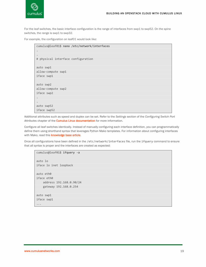
For the leaf switches, the basic interface configuration is the range of interfaces from swp1 to swp52. On the spine
switches, the range is swp1 to swp32.
For example, the configuration on leaf01 would look like:
cumulus@leaf01$ nano /etc/network/interfaces
.
.
# physical interface configuration
auto swp1
allow-compute swp1
iface swp1
auto swp2
allow-compute swp2
iface swp2
.
.
auto swp52
iface swp52
Additional attributes such as speed and duplex can be set. Refer to the Settings section of the Configuring Switch Port
Attributes chapter of the Cumulus Linux documentation for more information.
Configure all leaf switches identically. Instead of manually configuring each interface definition, you can programmatically
define them using shorthand syntax that leverages Python Mako templates. For information about configuring interfaces
with Mako, read this knowledge base article.
Once all configurations have been defined in the /etc/network/interfaces file, run the ifquery command to ensure
that all syntax is proper and the interfaces are created as expected:
cumulus@leaf01$ ifquery -a
auto lo
iface lo inet loopback
auto eth0
iface eth0
address 192.168.0.90/24
gateway 192.168.0.254
auto swp1
iface swp1
...

OPENSTACK AND CUMULUS LINUX: VALIDATED DESIGN GUIDE
20
Once all configurations have been defined in /etc/network/interfaces, apply the configurations to ensure they are
loaded into the kernel. There are several methods for applying configuration changes depending on when and what
changes you want to apply:
Command Action
sudo ifreload -a Parse interfaces labelled with auto that have been added to or modified in the
configuration file, and apply changes accordingly.
Note: This command is disruptive to traffic only on interfaces that have been
modified.
sudo service networking restart Restart all interfaces labelled with auto as defined in the configuration file,
regardless of what has or has not been recently modified.
Note: This command is disruptive to all traffic on the switch, including the eth0
management network.
sudo ifup <swpX> Parse an individual interface labelled with auto as defined in the configuration
file and apply changes accordingly.
Note: This command is disruptive to traffic only on interface swpX.
For example, on leaf01, to apply the new configuration to all changed interfaces labeled with auto:
cumulus@leaf01:~$ sudo ifreload -a
or individually:
cumulus@leaf01:~$ sudo ifup swp1
cumulus@leaf01:~$ sudo ifup swp2
.
.
.
cumulus@leaf01:~$ sudo ifup swp52
The above configuration in the /etc/network/interfaces file is persistent, which means the configuration applies even
after you reboot the switch. Another option to test network connectivity is to run a shell loop to bring up each front-panel
interface temporarily (until the next reboot), so that LLDP traffic can flow. This lets you verify the wiring is done correctly in
the next step:
cumulus@spine01$ for i in `grep '^swp' /var/lib/cumulus/porttab | cut -f1`; do
sudo ip link set dev $i up; done
Repeat the above steps on each of “spine02”, “leaf01”, “leaf02”, “leaf03”, and “leaf04”, changing the hostname
appropriately in each command or file.

BUILDING AN OPENSTACK CLOUD WITH CUMULUS LINUX
www.cumulusnetworks.com 21
3. Verify Connectivity
Back on spine01, use LLDP to verify that the cabling is correct, according to the cabling diagram:
cumulus@spine01$ sudo lldpctl | less
… snip …
-------------------------------------------------------------------------------
Interface: swp31, via: LLDP, RID: 4, Time: 0 day, 00:12:10
Chassis:
ChassisID: mac 44:38:39:00:49:0a
SysName: spine02
SysDescr: Cumulus Linux
Capability: Bridge, off
Capability: Router, on
Port:
PortID: ifname swp31
PortDescr: swp31
-------------------------------------------------------------------------------
Interface: swp32, via: LLDP, RID: 4, Time: 0 day, 00:12:10
Chassis:
ChassisID: mac 44:38:39:00:49:0a
SysName: spine02
SysDescr: Cumulus Linux
Capability: Bridge, off
Capability: Router, on
Port:
PortID: ifname swp32
PortDescr: swp32
-------------------------------------------------------------------------------
The output above shows only the last 2 interfaces, which you can see are correctly connected to the other spine switch,
based on the SysName field being spine02 (shown in green above). Verify that the remote-side interfaces are correct per
the wiring diagram, using the “PortID” field.
Note: Type q to quit less when you are done verifying.
Repeat the lldpctl command on spine02 to verify the rest of the connectivity.
4. Set Up Physical Servers
Install Ubuntu Server 14.04 LTS release on each server, as described in Ubuntu’s Installing from CD documentation.
During the install, configure the two drives into a RAID1 mirror, and then configure LVM on the mirror. Create a 1G swap
partition, and a 50G root partition. Leave the rest of the mirror’s space free for the creation of VMs.
Make sure that openssh server is installed, and configure the management network such that you have out-of-band SSH
access to the servers. As part of the installation process you will create a user with sudo access. Remember the username
and password you created for later.
Name the controller node (the one attached to swp1 on leaf01/leaf02) controller and name the compute nodes
compute01, compute02, and so on.
Populate the hostname alias for the controller and each of the compute nodes in the /etc/hosts file. Using the name
“controller” matches the sample configurations in the official OpenStack install guide. Edit /etc/hosts file on the
controller and each compute node, by adding the following entries at the end:

OPENSTACK AND CUMULUS LINUX: VALIDATED DESIGN GUIDE
22
10.254.192.1 controller
10.254.192.2 compute01
10.254.192.3 compute02
...
5. Configure Spine Switches
Enable MLAG Peering between Switches
An instance of the clagd daemon runs on each MLAG switch member to keep track of various networking information,
including MAC addresses, which are needed to maintain the peer relationship. clagd communicates with its peer on the
other switch across a Layer 3 interface between the two switches. This Layer 3 network should not be advertised by routing
protocols, nor should the VLAN be trunked anywhere else in the network. This interface is designed to be a keep-alive
reachability test and for synchronizing the switch state across the directly attached peer bond.
Create the VLAN subinterface for clagd communication and assign an IP address for this subinterface. A unique .1q tag is
recommended to avoid mixing data traffic with the clagd control traffic.
To enable MLAG peering between switches, configure clagd on each switch by creating a peerlink subinterface in
/etc/network/interfaces with a unique .1q tag. Set values for the following parameters under the peerlink
subinterface:
address. The local IP address/netmask of this peer switch.
o Cumulus Networks recommends you use a link local address; for example 169.254.1.X/30.
clagd-enable. Set to yes (default).
clagd-peer-ip. Set to the IP address assigned to the peer interface on the peer switch.
clagd-backup-ip Set to an IP address on the peer switch reachable independently of the peerlink. For
example, the management interfaces or a routed interface that does not traverse the peerlink.
clagd-sys-mac. Set to a unique MAC address you assign to both peer switches.
o Cumulus Networks recommends you use addresses within the Cumulus Linux reserved range of
44:38:39:FF:00:00 through 44:38:39:FF:FF:FF.
On both spine switches, edit /etc/network/interfaces and add the following sections at the bottom:
#Bond for the peerlink. MLAG control traffic and data when links are down.
auto peerlink
iface peerlink
bond-slaves swp31 swp32
bond-mode 802.3ad
bond-miimon 100
bond-use-carrier 1
bond-lacp-rate 1
bond-min-links 1
bond-xmit-hash-policy layer3+4
mtu 9000

BUILDING AN OPENSTACK CLOUD WITH CUMULUS LINUX
www.cumulusnetworks.com 23
On spine01, add a VLAN for the MLAG peering communications:
#VLAN for the MLAG control traffic.
auto peerlink.4094
iface peerlink.4094
address 169.254.255.1/30
clagd-enable yes
clagd-peer-ip 169.254.255.2
clagd-backup-ip 192.168.0.95/24
clagd-sys-mac 44:38:39:ff:00:00
On spine02, add a VLAN for the MLAG peering communications. Note the change of the last octet in the address and
clagd-peer-ip lines:
#VLAN for the MLAG control traffic.
auto peerlink.4094
iface peerlink.4094
address 169.254.255.2/30
clagd-enable yes
clagd-peer-ip 169.254.255.1
clagd-backup-ip 192.168.0.94/24
clagd-sys-mac 44:38:39:ff:00:00
On both spine switches, bring up the peering interfaces. The --with-depends option tells ifup to bring up the peer first,
since peerlink.4094 depends on it:
cumulus@spine0N:~$ sudo ifup --with-depends peerlink.4094
On spine01, verify that you can ping spine02:
cumulus@spine01$ ping -c 3 169.254.255.2
PING 169.254.255.2 (169.254.255.2) 56(84) bytes of data.
64 bytes from 169.254.255.2: icmp_req=1 ttl=64 time=0.716 ms
64 bytes from 169.254.255.2: icmp_req=2 ttl=64 time=0.681 ms
64 bytes from 169.254.255.2: icmp_req=3 ttl=64 time=0.588 ms
--- 169.254.255.2 ping statistics ---
3 packets transmitted, 3 received, 0% packet loss, time 2001ms
rtt min/avg/max/mdev = 0.588/0.661/0.716/0.061 ms
Now on both spine switches, verify that the peers are connected:
cumulus@spine01:~$ clagctl
The peer is alive
Peer Priority, ID, and Role: 32768 44:38:39:00:49:87 secondary
Our Priority, ID, and Role: 32768 44:38:39:00:49:06 primary
Peer Interface and IP: peerlink.4094 169.254.255.2
Backup IP: 192.168.0.95 (active)
System MAC: 44:38:39:ff:00:00
The MAC addresses in the output vary depending on the MAC addresses issued to your hardware.

OPENSTACK AND CUMULUS LINUX: VALIDATED DESIGN GUIDE
24
Now that the spines are peered, create the bonds for the connections to the leaf switches. On both spine switches, edit
/etc/network/interfaces and add the following at the end:
#Bonds down to the pairs of leafs.
auto downlink1
allow-leafs downlink1
iface downlink1
bond-slaves swp1 swp2
bond-mode 802.3ad
bond-miimon 100
bond-use-carrier 1
bond-lacp-rate 1
bond-min-links 1
bond-xmit-hash-policy layer3+4
mtu 9000
clag-id 1
auto downlink2
allow-leafs downlink2
iface downlink2
bond-slaves swp3 swp4
bond-mode 802.3ad
bond-miimon 100
bond-use-carrier 1
bond-lacp-rate 1
bond-min-links 1
bond-xmit-hash-policy layer3+4
mtu 9000
clag-id 2
You can add more stanzas for more pairs of leaf switches as needed, modifying the sections in green above. For example,
to add a third stanza, you’d use downlink3; the corresponding swp interfaces would be swp5 and swp6 and clag-id 3.
Bridge together the MLAG peer bond and all the leaf bonds. On both switches, edit /etc/network/interfaces and add
the following at the end:
#Bridge that connects our peer and downlinks to the leafs.
auto bridge
iface bridge
bridge-vlan-aware yes
bridge-ports peerlink downlink1 downlink2
bridge-stp on
bridge-vids 100-2000
mstpctl-treeprio 12288
If you added more downlink# interfaces in the previous step, add them to the bridge-ports line, at the end of the line.
If you’re familiar with the traditional Linux bridge mode, you may be surprised that we called the bridge bridge instead of
br0. The reason is that we’re using the new VLAN-aware Linux bridge mode in this example, which doesn’t require multiple
bridge interfaces for common configurations. It trades off some of the flexibility of the traditional mode in return for
supporting very large numbers of VLANs. See the Cumulus Linux documentation for more information on the two bridging
modes supported in Cumulus Linux.

BUILDING AN OPENSTACK CLOUD WITH CUMULUS LINUX
www.cumulusnetworks.com 25
Finally, on both spine01 and spine02, bring up all the interfaces, bonds, and bridges. The --with-depends option tells
ifup to bring up any down interfaces that are needed by the bridge:
cumulus@spine0N:~$ sudo ifup --with-depends bridge
6. Configure Each Pair of Leaf Switches
On each leaf switch, edit /etc/network/interfaces, and add the following sections at the bottom:
#Bond for the peer link. MLAG control traffic and data when links are down.
auto peerlink
iface peerlink
bond-slaves swp51 swp52
bond-mode 802.3ad
bond-miimon 100
bond-use-carrier 1
bond-lacp-rate 1
bond-min-links 1
bond-xmit-hash-policy layer3+4
mtu 9000
On odd numbered leaf switches, add a VLAN for the MLAG peering communications. Note that the last octet of the clagd-
sys-mac must be the same for each switch in a pair, but incremented for subsequent pairs. For example, leaf03 and
leaf04 should have 03 as the last octet:
#VLAN for the MLAG control traffic.
auto peerlink.4094
iface peerlink.4094
address 169.254.255.1/30
clagd-enable yes
clagd-peer-ip 169.254.255.2
clagd-backup-ip 192.168.0.91/24
clagd-sys-mac 44:38:39:ff:00:02
On even numbered leaf switches, add a VLAN for the MLAG peering communications. Note the change of the last octet in
the address and clagd-sys-peer-ip lines. Also note that for subsequent pairs of switches, the last octet of clagd-
sys-mac must match as described for the odd-numbered switches:
#VLAN for the MLAG control traffic.
auto peerlink.4094
iface peerlink.4094
address 169.254.255.2/30
clagd-enable yes
clagd-peer-ip 169.254.255.1
clagd-backup-ip 192.168.0.90/24
clagd-sys-mac 44:38:39:ff:00:02
On each leaf switch, bring up the peering interfaces:
cumulus@leaf0N:~$ sudo ifup --with-depends peerlink.4094

OPENSTACK AND CUMULUS LINUX: VALIDATED DESIGN GUIDE
26
On each odd numbered leaf switch, verify that you can ping its corresponding even-numbered leaf switch:
cumulus@leaf0N:~$ ping -c 3 169.254.255.2
PING 169.254.255.2 (169.254.255.2) 56(84) bytes of data.
64 bytes from 169.254.255.2: icmp_req=1 ttl=64 time=0.716 ms
64 bytes from 169.254.255.2: icmp_req=2 ttl=64 time=0.681 ms
64 bytes from 169.254.255.2: icmp_req=3 ttl=64 time=0.588 ms
--- 169.254.255.2 ping statistics ---
3 packets transmitted, 3 received, 0% packet loss, time 2001ms
rtt min/avg/max/mdev = 0.588/0.661/0.716/0.061 ms
Now, on each leaf switch, verify that the peers are connected:
cumulus@leaf0N:~$ clagctl
The peer is alive
Peer Priority, ID, and Role: 32768 6c:64:1a:00:39:5a primary
Our Priority, ID, and Role: 32768 6c:64:1a:00:39:9b secondary
Peer Interface and IP: peerlink.4094 169.254.255.2
Backup IP: 192.168.0.91 (active)
System MAC: 44:38:39:ff:00:02
Now that the leafs are peered, create the uplink bonds connecting the leafs to the spines. On each leaf switch, edit
/etc/network/interfaces and add the following at the end:
#Bond up to the spines.
auto uplink
iface uplink
bond-slaves swp49 swp50
bond-mode 802.3ad
bond-miimon 100
bond-use-carrier 1
bond-lacp-rate 1
bond-min-links 1
bond-xmit-hash-policy layer3+4
mtu 9000
clag-id 1000
On each leaf switch, bring up the bond up to the spine:
cumulus@leaf0N:~$ sudo ifup --with-depends uplink
On each leaf switch, verify that the link to the spine is up:
cumulus@leaf0N:~$ ip link show dev uplink
2: uplink: <BROADCAST,MULTICAST,UP,LOWER_UP> mtu 9000 qdisc pfifo_fast state UP
qlen 1000
link/ether 44:38:39:00:49:06 brd ff:ff:ff:ff:ff:ff
The UP,LOWER_UP (shown in green above) line means that the bond itself is up (UP), and slave interfaces (swp49 and
swp50) are up (LOWER_UP).

BUILDING AN OPENSTACK CLOUD WITH CUMULUS LINUX
www.cumulusnetworks.com 27
On leaf01 and leaf02, and only leaf01 and leaf02, configure the interfaces going to the core/external routers. These are
associated with external VLAN (101), but are configured as access ports and therefore untagged. Edit
/etc/network/interfaces and add the following at the end:
auto swp48
iface swp48
bridge-access 101
mtu 9000
Create the bonds for the connections to the servers. On each leaf switch, edit /etc/network/interfaces and add the
following at the end:
#Bonds down to the host.
#Only one swp, because the other swp is on the peer switch.
auto compute01
allow-hosts compute01
iface compute01
bond-slaves swp1
bond-mode 802.3ad
bond-miimon 100
bond-lacp-rate 1
bond-min-links 1
bond-xmit-hash-policy layer3+4
bond-lacp-bypass-allow 1
mstpctl-portadminedge yes
mstpctl-bpduguard yes
clag-id 1
Repeat the above stanza for each front panel port that has servers attached. You’ll need to adjust compute01, swp1 and
the value for clag-id everywhere they appear (in green). For example, for swp2, change each compute01 to compute02
and swp1 to swp2, and change clag-id from 1 to 2.
Bridge together the MLAG peer bond, the uplink bond, and all the leaf bonds. On each leaf switch, edit
/etc/network/interfaces and add the following at the end:
#Bridge that connects our peer, uplink to the spines, and the hosts.
auto bridge
iface bridge
bridge-vlan-aware yes
bridge-ports uplink swp48 peerlink compute01 compute02 compute03
bridge-stp on
bridge-vids 100-2000
mstpctl-treeprio 16384
If you added more host# interfaces in the previous step, add them to the bridge-ports line, at the end of the line. Note
that swp48 (in green above) should only be present on leaf01 and leaf02, not on subsequent leafs.
Finally, on each leaf switch, bring up all the interfaces, bonds, and bridges:
cumulus@leaf0N:~$ sudo ifup --with-depends bridge

OPENSTACK AND CUMULUS LINUX: VALIDATED DESIGN GUIDE
28
7. Configure Host Devices
The server connected to swp1 on leaf01 and leaf02 is the OpenStack controller. It manages all the other servers, which run
VMs. ssh into it as the user you configured when installing the OS.
Configure the Uplinks
The server has two 10G interfaces, in this example they are called p1p1 and p2p2. They may be named differently on other
server hardware platforms.
The ifenslave package must be installed for bonding support, and the vlan package must be installed for VLAN support.
To install them, run:
cumulus@controller$ sudo apt-get install ifenslave vlan
For the bond to come up, the bonding driver needs to be loaded. Similarly, for VLANs, the 802.1q driver must be loaded. So
that they will be loaded automatically at boot time, edit /etc/modules and add the following to the end:
bonding
8021q
Now load the modules:
cumulus@controller$ sudo modprobe bonding
cumulus@controller$ sudo modprobe 8021q
Edit /etc/network/interfaces to add the following at the end:
#The bond, one subinterface goes to each leaf.
auto bond0
iface bond0 inet manual
up ip link set dev $IFACE up
down ip link set dev $IFACE down
bond-mode 802.3ad
bond-miimon 100
bond-lacp-rate 1
bond-slaves none
#First 10G link.
auto p1p1
iface p1p1 inet manual
bond-master bond0
#Second 10G link.
auto p1p2
iface p1p2 inet manual
bond-master bond0
#OpenStack Networking VXLAN (tunnel/overlay) VLAN
auto bond0.101
iface bond0.101 inet static
address 192.168.100.2
netmask 255.255.255.0
gateway 192.168.100.1

BUILDING AN OPENSTACK CLOUD WITH CUMULUS LINUX
www.cumulusnetworks.com 29
#OpenStack API VLAN
auto bond0.102
iface bond0.102 inet static
address 10.254.192.1
netmask 255.255.240.0
Note that Ubuntu uses ifupdown, while Cumulus Linux uses ifupdown2. The configuration format is similar, but many
constructs that work on the switch will not work in Ubuntu.
Now bring up the interfaces:
cumulus@controller$ sudo ifup -a
Verify that the VLAN interface is UP and LOWER_UP:
cumulus@controller$ sudo ip link show bond0.102
9: bond0.102@bond0: <BROADCAST,MULTICAST,UP,LOWER_UP> mtu 1500 qdisc noqueue
state UP mode DEFAULT group default
link/ether 90:e2:ba:7c:28:28 brd ff:ff:ff:ff:ff:ff
The remaining servers are all compute nodes. They run VMs, as directed by the controller. Connect to the node, using ssh
as the user you configured when installing the OS. In this example, that user is called cumulus.
Configure the uplinks. The server has two 10G interfaces; in this example they are called p1p1 and p2p2. They may be
named differently on other server hardware platforms.
The ifenslave package must be installed for bonding support, and the vlan package must be installed for VLAN support.
cumulus@compute01$ sudo apt-get install ifenslave vlan
For the bond to come up, the bonding driver needs to be loaded. Similarly, for VLANs, the 802.1q driver must be loaded. So
that they will be loaded automatically at boot time, edit /etc/modules and add the following to the end:
bonding
8021q
Now load the modules:
cumulus@compute0N:~$ sudo modprobe bonding
cumulus@compute0N:~$ sudo modprobe 8021q

OPENSTACK AND CUMULUS LINUX: VALIDATED DESIGN GUIDE
30
Edit /etc/network/interfaces and add the following at the end:
#The bond, one interface goes to each leaf.
auto bond0
iface bond0 inet manual
up ip link set dev $IFACE up
down ip link set dev $IFACE down
bond-mode 802.3ad
bond-miimon 100
bond-lacp-rate 1
bond-slaves none
#First 10G link.
auto p1p1
iface p1p1 inet manual
bond-master bond0
#Second 10G link.
auto p1p2
iface p1p2 inet manual
bond-master bond0
#OpenStack Networking VXLAN (tunnel/overlay) VLAN
auto bond0.101
iface bond0.101 inet static
address 192.168.100.3
netmask 255.255.240.0
gateway 192.168.100.1
#OpenStack API VLAN.
auto bond0.102
iface bond0.102 inet static
address 10.254.192.2
netmask 255.255.240.0
You’ll need to increment the API VLAN’s IP address (show in green above, on bond0.102) for each compute node. You’ll
also need to increment the VXLAN VLAN’s IP address (show in green above, on bond0.101). The examples given above are
for compute01. For compute02, you would use 10.254.192.3 and 192.168.100.4.
Note: Ubuntu uses ifupdown, while Cumulus Linux uses ifupdown2. The configuration format is similar, but many
advanced configurations that work on the switch will not work in Ubuntu.
Now bring up the interfaces:
cumulus@compute0N:~$ sudo ifup -a
Verify that the VLAN interface is UP and LOWER_UP:
cumulus@compute0N:~$ sudo ip link show bond0.102
9: bond0.102@bond0: <BROADCAST,MULTICAST,UP,LOWER_UP> mtu 1500 qdisc noqueue
state UP mode DEFAULT group default
link/ether 90:e2:ba:7c:28:28 brd ff:ff:ff:ff:ff:ff

BUILDING AN OPENSTACK CLOUD WITH CUMULUS LINUX
www.cumulusnetworks.com 31
Add a hostname alias for the controller. Edit /etc/hosts and add the following at the end:
10.254.192.1 controller
Verify that this node can talk to the controller over the API VLAN:
cumulus@compute0N:~$ ping -c 3 controller
PING controller (10.254.192.1) 56(84) bytes of data.
64 bytes from controller (10.254.192.1): icmp_seq=1 ttl=64 time=0.229 ms
64 bytes from controller (10.254.192.1): icmp_seq=2 ttl=64 time=0.243 ms
64 bytes from controller (10.254.192.1): icmp_seq=3 ttl=64 time=0.220 ms
--- controller ping statistics ---
3 packets transmitted, 3 received, 0% packet loss, time 1998ms
rtt min/avg/max/mdev = 0.220/0.230/0.243/0.019 ms
8. Install and Configure OpenStack Services
In the following section, before you follow the OpenStack install guide sections, read the notes mentioned in this document,
as they contain important additional information you’ll need. In some cases this will save a lot of trouble by avoiding errors
in the official documentation.
Use the official OpenStack Installation Guide for Ubuntu (Liberty Release). In the Liberty install guide, follow the instructions
as written, to install and configuring the devices, Identity service, Image, and Compute services. Note that you’ll have to
use sudo when installing the packages. The following notes indicate some additional information related to the
corresponding sections:
Add the Identity Service
Create OpenStack client environment scripts. This simplifies running commands as various OpenStack users; just source
the rc file any time you want to change users. To help identify the user environment sourced, it is beneficial to also set the
prompt in each script indicating the user. Append this line after the other export commands in the rc files:
export PS1='\u[OS_${OS_USERNAME}]@\h:\w\$ '
Add the Image Service
Verify operation. The guide assumes your server has direct access to the Internet; however, if you need an HTTP proxy to
access the Internet from your environment, you can specify the proxy prior to wget:
cumulus@controller$ http_proxy="http://MY.HTTP.PROXY/" wget http://…
Add the Compute Service
Install and configure the controller node
An error occurs while installing the compute service. The default configuration of the Nova package has a bug wherein the
default nova.conf has the key logdir; however, the key should be log_dir. You can fix this easily using the following
command:
sed -i "s/\(log\)\(dir\)/\1_\2/g" /etc/nova/nova.conf
Alternately, make the following change in /etc/nova.conf:
[DEFAULT]
...
#Ubuntu has a packaging issue, make this fix: logdir -> log_dir
log_dir=/var/log/nova

OPENSTACK AND CUMULUS LINUX: VALIDATED DESIGN GUIDE
32
Install and Configure the Compute Node
As mentioned above, you need to correct the default nova.conf again for the directive log_dir. There is also an error in
the OpenStack guide in the configuration of the RabbitMQ settings. This appears to be a bug, and the settings must be
configured under the [DEFAULT] section, rather than the [oslo_messaging_rabbit] section of the ini file, as the Liberty guide
instructs. Make the following changes to the /etc/nova/nova.conf to correct the rabbitmq and log_dir issues:
[DEFAULT]
...
#Ubuntu has a packaging issue, make this fix: logdir -> log_dir
log_dir=/var/log/nova
...
rpc_backend = rabbit
rabbit_host = os-controller
rabbit_userid = openstack
rabbit_password = cn321
[oslo_messaging_rabbit]
# https://bugs.launchpad.net/openstack-manuals/+bug/1453682
Add the Networking Service
Working with Neutron requires some understanding of the requirements for the OpenStack deployment. Neutron is multi-
faceted, in that it can provide layer 3 routing, layer 2 switching, DHCP service, firewall services, and load balancing
services, to name just a few. The OpenStack Liberty install guide provides two options for setting up networking:
1) Provider networks — This is the simpler deployment, relying on layer 2 (bridging/switching) services and VLAN
segmentation to forward virtual network traffic out to the networking infrastructure. It relies on the physical network
infrastructure for layer 3 services. It does provide the DHCP service to handle addressing of the virtual instances. This
is similar to the VMware networking design.
2) Self-service networks — This option adds to the provider network option by including layer 3 (routing) services using
NAT. This also enables "self-service” networks using network segmentation methods like VLAN or VXLAN. Furthermore,
this option provides the foundation for advanced services like FWaaS, and LBaaS, which are not covered in this guide.
This guide uses networking option 2. Where the OpenStack guide provides links to select either networking option, select
option 2. Notice at the bottom of the networking option sections the links that take you to the correct next section, rather
than simply clicking the “next” arrow. These links actually jump back to where the guide initially provided the option links.
Install and Configure the Controller Node
Choose Configure Networking Options > Networking Option 2: Self-service Networks
Configure the Modular Layer 2 (ML2) Plugin
In the ML2 configuration, the flat network is used for the layer 3 routed traffic. The OpenStack guide only specifies the
VXLAN tenant separation, but this design uses VLANs for tenant separation. Therefore you need to add the [ml2_type_vlan]
network type to allow for creating VLAN segmentation of tenants. This utilizes the same “public” interface, and restricts the
VLANs to 201-299, making the “public” interface an 802.1q trunk. Leave the VXLAN configuration, in case you want to use
VXLAN tenant separation in the future.
[ml2]
type_drivers = flat,vlan,vxlan
tenant_network_types = vxlan
mechanism_drivers = linuxbridge,l2population
extension_drivers = port_security
[ml2_type_flat]

BUILDING AN OPENSTACK CLOUD WITH CUMULUS LINUX
www.cumulusnetworks.com 33
flat_networks = public
[ml2_type_vlan]
network_vlan_ranges = public:201:299
[ml2_type_vxlan]
vni_ranges = 1:1000
[securitygroup]
enable_ipset = True
Configure the Linux Bridge Agent
In this section you are mapping the physical host interfaces to the provider network names. In the [linux_bridge] section, for
the physical interface mappings, the variable PHYSICAL_INTERFACE_NAME is bond0. Under the [vxlan] section, the
OVERLAY_INTERFACE_IP_ADDRESS variable is the local IP address for the bond0.101 interface.
[linux_bridge]
physical_interface_mappings = public:bond0
[vxlan]
enable_vxlan = True
local_ip = 192.168.100.2
l2_population = True
[agent]
prevent_arp_spoofing = True
[securitygroup]
firewall_driver = neutron.agent.linux.iptables_firewall.IptablesFirewallDriver
enable_security_group = True
Install and Configure the Compute Node
Choose Configure Networking Options > Networking Option 2: Self-service Networks
Configure the Linux Bridge Agent
The compute nodes have a simpler setup where the Linux bridge agent just needs to know the logical-to-physical interface
mapping. As above, you are mapping the physical host interface to the provider network name “public”. In the [linux_bridge]
section, for the physical interface mappings, the variable PHYSICAL_INTERFACE_NAME is bond0. Under the [vxlan] section,
the OVERLAY_INTERFACE_IP_ADDRESS variable is the local IP address for the bond0.101 interface.
[linux_bridge]
physical_interface_mappings = public:bond0
[vxlan]
enable_vxlan = True
local_ip = 192.168.100.3
l2_population = True
[agent]
prevent_arp_spoofing = True

OPENSTACK AND CUMULUS LINUX: VALIDATED DESIGN GUIDE
34
[securitygroup]
firewall_driver = neutron.agent.linux.iptables_firewall.IptablesFirewallDriver
enable_security_group = True
Repeat the all the steps in this section on the rest of the compute nodes, changing the hostnames and IP addresses
appropriately in each command or file.
Add the Dashboard
Follow the guide to install the Horizon dashboard, then remove the openstack-dashboard-ubuntu-theme package, as
it may cause rendering issues:
cumulus@controller$ sudo apt-get install apache2 memcached libapache2-mod-wsgi
openstack-dashboard
cumulus@controller$ sudo apt-get remove --purge openstack-dashboard-ubuntu-theme
Installing the Horizon Web interface is optional. If installed, it is not a good idea to expose the Horizon Web interface to
untrusted networks without hardening the configuration.
9. Create Project Networks
Launch an Instance
In this final section, follow the guide to set up the virtual networks, generate a key pair, and add security group rules. Below
is more detail on creating the provider and private networks.
Create Virtual Networks
Public provider network. In general, these steps follow the OpenStack Liberty guide. In Neutron, the network is “owned” by
the project or tenant. Alternately, a network may be shared by all projects using the --shared option. It is important to
remember that the “Admin” user is in the “Admin” project.
Create the Public Provider Network
This creates the external layer 3 network, used for routing traffic from any of the tenant subnets via the tenant routers.
First use the neutron net-create command, adding the --shared option to allow any project to use this network. The -
-provider options reference the Neutron ML2 plugin providing the service. The physical_network is the same name
specified in the ml2_conf.ini. The network_type is flat, meaning the traffic is untagged out of the bond0 interface.
Furthermore, since you are creating an “external” network for tenant routers to connect to the outside, this network is
designated as such using the --router:external option.
cumulus[os_admin]@os-controller:~$ neutron net-create external \
--shared --router:external \
--provider:physical_network public \
--provider:network_type flat
Next create the IP address subnet to be used here. This provides DHCP for connecting tenant routers, as well as the
floating IP addresses allocated to instances. This would typically be a publicly routable subnet, though this example uses
10.1.0.0/24:
cumulus[os_admin]@os-controller:~$ neutron subnet-create external 10.1.0.0/24 \
--name ext-net --allocation-pool start=10.1.0.100,end=10.1.0.199 \
--dns-nameserver 8.8.8.8 --gateway 10.1.0.1

BUILDING AN OPENSTACK CLOUD WITH CUMULUS LINUX
www.cumulusnetworks.com 35
Private Project Networks
Create the private project network using VLAN segmentation
Here you need to do things a little differently to make it a little more deterministic. Using the neutron net-create
command, the physical_network is the same name specified in the ml2_conf.ini. The network_type is vlan, and
the segmentation_id is the VLAN ID for the tenant.
As the admin user, you can create this network on behalf of another project/tenant (the ‘demo’ project in this case), so you
need the tenant ID. The admin user can specify that the network is tied to a given tenant using the --tenant option. Once
the network is created for that tenant, the resource can be configured by any member of the designated tenant.
TENANT_NAME=demo
TENANT_ID="$(openstack project show $TENANT_NAME | grep " id " | head -n1 | \
awk -F'|' '{print $3;}' | xargs -n1 echo)"
cumulus[os_admin]@os-controller:~$ neutron net-create vmnet1 \
--tenant-id $TENANT_ID \
--provider:physical_network public \
--provider:network_type vlan \
--provider:segmentation_id 201
Why can’t the ‘demo’ user create their own neutron network? This is enforced by the default administrative policy in
OpenStack, thus permitting the ‘admin’ user, or any member of the ‘admin’ project, super-user rights on the cluster.
Thinking about it more, if you allow any regular tenant user to do any operation, there is no point having roles and projects,
and the end result would likely be chaos. Therefore aligning with industry standards, the user/role/project policy is
designed to work in a structured and orderly manner. To look at the policies for the entire OpenStack cluster, look at the
file /etc/nova/policy.json.
Next, source the open.rc script for the private tenant using the “demo” user to follow along with the OpenStack guide.
Create a subnet for the network using the neutron subnet-create command. The ––allocation-pool defines the
DHCP address pool used on the subnet.
cumulus[os_demo]@os-controller:~$ neutron subnet-create vmnet1 10.10.1.0/24 \
--name SUBNET1 --allocation-pool start=10.10.1.100,end=10.10.1.199 \
--dns-nameserver 8.8.8.8 --gateway 10.10.1.1
Basic Layer-2 Switched Connectivity
You can stop here for this tenant, and it will simply have the common networking connectivity that is most analogous to the
way VMware vSwitch connections operate. Here the instance or VM will have basic layer 2 reachability to the network
infrastructure switches. These devices can easily handle the inter-tenant routing, and intra-tenant switching.
However, if this instance needs to send traffic out to the Internet, it must have an address from a publicly routable subnet,
otherwise it will require NAT, possibly at the enterprise edge router or firewall. If there is no NAT-enabled device at the edge
of the network, then the layer 3 agent within OpenStack Neutron can provide this functionality as north-south traffic
egresses the OpenStack cluster.
Create a Router
This section explains how to create a tenant router, which connects to the provider network. It follows the OpenStack guide.
cumulus[os_demo]@os-controller:~$ neutron router-create demo-rtr
cumulus[os_demo]@os-controller:~$ neutron router-interface-add demo-rtr SUBNET1
cumulus[os_demo]@os-controller:~$ neutron router-gateway-set demo-rtr external
Now that you have a router and an external subnet, you can allocate a floating IP address to an instance that requires
external network connectivity. This simply creates the source NAT IP address that the traffic from an instance uses to send

OPENSTACK AND CUMULUS LINUX: VALIDATED DESIGN GUIDE
36
traffic out on the “public” network, and allows traffic to return. Since you are using the Horizon Web console to launch your
instance, you can create and associate the floating IP address for the instance there.
10. Creating VMs on OpenStack
Launch an Instance on the Public Network
Since the external or “public” network is simply another Neutron network, you can put an instance on the “public” network,
and it will get an address via DHCP, thus directly providing an address from the associated DHCP pool. This instance uses
the flat or untagged network.
Launch an Instance on the Private Network
Typically, the instance will be located on a private tenant network. This allows for the neutron network to easily connect to
the network infrastructure devices, maintaining tenant separation using VLAN segmentation. Therefore the traffic is sent
out from the compute host, on an Ethernet trunk as VLAN-tagged frames.
The instance may require connectivity to the external “public” network. To allow an instance to send traffic on the “public”
network, requires the use of floating-IP’s allocated from the DHCP address pool. This traffic will transit the L3-agent, and
exit using the flat or untagged network.
Launch an Instance from Horizon
The OpenStack Web UI named Horizon provides a nice Web interface with many of the typical enterprise features for a
virtualization platform. Simply point a Web browser at http://192.168.100.2/horizon and log in (user: admin, password:
adminpw).
Orchestration Service
The Heat service provides an automation infrastructure, using templates to assist in deployment. The templates provide an
easy way to create most OpenStack resource types, such as instances, floating IPs, volumes, security groups and users.

CONCLUSION
www.cumulusnetworks.com 37
Conclusion
Summary
The fundamental abstraction of hardware from software and providing customers a choice through a hardware agnostic
approach is core to the philosophy of Cumulus Networks and fits very well within the software-centric, commodity hardware
friendly design of OpenStack.
Just as OpenStack users have choice in server compute and storage, they can tap the power of Open Networking and
select from a broad range of switch providers running Cumulus Linux.
Choice and CapEx savings are only the beginning. OpEx savings come from agility through automation. Just as OpenStack
orchestrates the cloud by enabling the automated provisioning of hosts, virtual networks, and VMs through the use of APIs
and interfaces, Cumulus Linux enables network and data center architects to leverage automated provisioning tools and
templates to define and provision physical networks.
References
Article/Document URL
OpenStack Documentation
• Database Install Guide
• Message Queue Install Guide
• Keystone Install Guide
• Users Install Guide
• Services Install Guide
• Openrc Install Guide
• Keystone Verification Install Guide
• Glance Install Guide
• Nova Install Guide
• Neutron Network Install Guide
http://docs.openstack.org/liberty/install-guide-ubuntu/
Cumulus Linux Documentation
• Quick Start Guide
• Understanding Network Interfaces
• MLAG
• LACP Bypass
• Authentication, Authorization, and Accounting
• Zero Touch Provisioning
https://docs.cumulusnetworks.com/display/DOCS

OPENSTACK AND CUMULUS LINUX: VALIDATED DESIGN GUIDE
38
Cumulus Linux KB Articles
• Configuring /etc/network/interfaces with
Mako
• Demos and Training
• Installing collectd and graphite
• Manually Putting All Switch Ports into a Single
VLAN
https://support.cumulusnetworks.com/hc/en-
us/articles/202868023
https://support.cumulusnetworks.com/hc/en-
us/sections/200398866
https://support.cumulusnetworks.com/hc/en-
us/articles/201787586
https://support.cumulusnetworks.com/hc/en-
us/articles/203748326
Cumulus Linux Product Information
• Software Pricing
• Hardware Compatibility List
http://cumulusnetworks.com/product/pricing/
http://cumulusnetworks.com/support/linux-hardware-
compatibility-list/
Cumulus Linux Downloads http://cumulusnetworks.com/downloads/
Cumulus Linux Repository http://repo.cumulusnetworks.com
Cumulus Networks GitHub Repository https://github.com/CumulusNetworks/

APPENDIX A: EXAMPLE /ETC/NETWORK/INTERFACES CONFIGURATIONS
www.cumulusnetworks.com 39
Appendix A: Example /etc/network/interfaces
Configurations
leaf01
cumulus@leaf01$ cat /etc/network/interfaces
auto eth0
iface eth0
address 192.168.0.90/24
gateway 192.168.0.254
# physical interface configuration
auto swp1
iface swp1
mtu 9000
auto swp2
iface swp2
mtu 9000
auto swp3
iface swp3
mtu 9000
.
.
auto swp48
iface swp48
bridge-access 101
mtu 9000
.
.
auto swp52
iface swp52
mtu 9000
# peerlink bond for clag
#Bond for the peer link. MLAG control traffic and data when links are down.
auto peerlink
iface peerlink
bond-slaves swp51 swp52
bond-mode 802.3ad
bond-miimon 100

OPENSTACK AND CUMULUS LINUX: VALIDATED DESIGN GUIDE
40
bond-use-carrier 1
bond-lacp-rate 1
bond-min-links 1
bond-xmit-hash-policy layer3+4
mtu 9000
#VLAN for the MLAG control traffic.
auto peerlink.4094
iface peerlink.4094
address 169.254.255.1/30
clagd-peer-ip 169.254.255.2
clagd-backup-ip 192.168.0.91/24
clagd-sys-mac 44:38:39:ff:00:02
#Bond up to the spines.
auto uplink
iface uplink
bond-slaves swp49 swp50
bond-mode 802.3ad
bond-miimon 100
bond-use-carrier 1
bond-lacp-rate 1
bond-min-links 1
bond-xmit-hash-policy layer3+4
mtu 9000
clag-id 1000
#Bonds down to the host. Only one swp, because the other swp is on the peer
switch.
auto compute01
allow-hosts compute01
iface compute01
bond-slaves swp1
bond-mode 802.3ad
bond-miimon 100
bond-lacp-rate 1
bond-min-links 1
bond-xmit-hash-policy layer3+4
bond-lacp-bypass-allow 1
mstpctl-portadminedge yes
mstpctl-bpduguard yes
clag-id 1
auto compute02
allow-hosts compute02
iface compute02
bond-slaves swp2
bond-mode 802.3ad
bond-miimon 100
bond-lacp-rate 1

APPENDIX A: EXAMPLE /ETC/NETWORK/INTERFACES CONFIGURATIONS
www.cumulusnetworks.com 41
bond-min-links 1
bond-xmit-hash-policy layer3+4
bond-lacp-bypass-allow 1
mstpctl-portadminedge yes
mstpctl-bpduguard yes
clag-id 2
auto controller
allow-hosts controller
iface controller
bond-slaves swp3
bond-mode 802.3ad
bond-miimon 100
bond-lacp-rate 1
bond-min-links 1
bond-xmit-hash-policy layer3+4
bond-lacp-bypass-allow 1
mstpctl-portadminedge yes
mstpctl-bpduguard yes
clag-id 3
#Bridge that connects our peer, uplink to the spines, and the hosts.
auto bridge
iface bridge
bridge-vlan-aware yes
bridge-ports uplinks swp48 peerlink compute01 compute02 compute03
bridge-stp on
bridge-vids 100-2000
mstpctl-treeprio 16384

OPENSTACK AND CUMULUS LINUX: VALIDATED DESIGN GUIDE
42
leaf02
cumulus@leaf02$ cat /etc/network/interfaces
auto eth0
iface eth0
address 192.168.0.91/24
gateway 192.168.0.254
# physical interface configuration
auto swp1
iface swp1
mtu 9000
auto swp2
iface swp2
mtu 9000
auto swp3
iface swp3
mtu 9000
.
.
auto swp48
iface swp48
bridge-access 101
mtu 9000
.
.
auto swp52
iface swp52
mtu 9000
# peerlink bond for clag
#Bond for the peer link. MLAG control traffic and data when links are down.
auto peerlink
iface peerlink
bond-slaves swp51 swp52
bond-mode 802.3ad
bond-miimon 100
bond-use-carrier 1
bond-lacp-rate 1
bond-min-links 1
bond-xmit-hash-policy layer3+4
mtu 9000
#VLAN for the MLAG control traffic.
auto peerlink.4094

APPENDIX A: EXAMPLE /ETC/NETWORK/INTERFACES CONFIGURATIONS
www.cumulusnetworks.com 43
iface peerlink.4094
address 169.254.255.2/30
clagd-peer-ip 169.254.255.1
clagd-backup-ip 192.168.0.90/24
clagd-sys-mac 44:38:39:ff:00:02
#Bond up to the spines.
auto uplink
iface uplink
bond-slaves swp49 swp50
bond-mode 802.3ad
bond-miimon 100
bond-use-carrier 1
bond-lacp-rate 1
bond-min-links 1
bond-xmit-hash-policy layer3+4
mtu 9000
clag-id 1000
#Bonds down to the host. Only one swp, because the other swp is on the peer
switch.
auto compute01
allow-hosts compute01
iface compute01
bond-slaves swp1
bond-mode 802.3ad
bond-miimon 100
bond-lacp-rate 1
bond-min-links 1
bond-xmit-hash-policy layer3+4
bond-lacp-bypass-allow 1
mstpctl-portadminedge yes
mstpctl-bpduguard yes
clag-id 1
auto compute02
allow-hosts compute02
iface compute02
bond-slaves swp2
bond-mode 802.3ad
bond-miimon 100
bond-lacp-rate 1
bond-min-links 1
bond-xmit-hash-policy layer3+4
bond-lacp-bypass-allow 1
mstpctl-portadminedge yes
mstpctl-bpduguard yes
clag-id 2

OPENSTACK AND CUMULUS LINUX: VALIDATED DESIGN GUIDE
44
auto controller
allow-hosts controller
iface controller
bond-slaves swp3
bond-mode 802.3ad
bond-miimon 100
bond-lacp-rate 1
bond-min-links 1
bond-xmit-hash-policy layer3+4
bond-lacp-bypass-allow 1
mstpctl-portadminedge yes
mstpctl-bpduguard yes
clag-id 3
#Bridge that connects our peer, uplink to the spines, and the hosts.
auto bridge
iface bridge
bridge-vlan-aware yes
bridge-ports uplinks swp48 peerlink compute01 compute02 compute03
bridge-stp on
bridge-vids 100-2000
mstpctl-treeprio 16384

APPENDIX A: EXAMPLE /ETC/NETWORK/INTERFACES CONFIGURATIONS
www.cumulusnetworks.com 45
leaf03
cumulus@leaf03$ cat /etc/network/interfaces
auto eth0
iface eth0
address 192.168.0.92/24
gateway 192.168.0.254
# physical interface configuration
auto swp1
iface swp1
mtu 9000
auto swp2
iface swp2
mtu 9000
auto swp3
iface swp3
mtu 9000
.
.
auto swp52
iface swp52
mtu 9000
# peerlink bond for clag
#Bond for the peer link. MLAG control traffic and data when links are down.
auto peerlink
iface peerlink
bond-slaves swp51 swp52
bond-mode 802.3ad
bond-miimon 100
bond-use-carrier 1
bond-lacp-rate 1
bond-min-links 1
bond-xmit-hash-policy layer3+4
mtu 9000
#VLAN for the MLAG control traffic.
auto peerlink.4094
iface peerlink.4094
address 169.254.255.1/30
clagd-peer-ip 169.254.255.2
clagd-backup-ip 192.168.0.94/24
clagd-sys-mac 44:38:39:ff:00:03
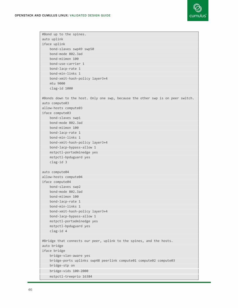
OPENSTACK AND CUMULUS LINUX: VALIDATED DESIGN GUIDE
46
#Bond up to the spines.
auto uplink
iface uplink
bond-slaves swp49 swp50
bond-mode 802.3ad
bond-miimon 100
bond-use-carrier 1
bond-lacp-rate 1
bond-min-links 1
bond-xmit-hash-policy layer3+4
mtu 9000
clag-id 1000
#Bonds down to the host. Only one swp, because the other swp is on peer switch.
auto compute03
allow-hosts compute03
iface compute03
bond-slaves swp1
bond-mode 802.3ad
bond-miimon 100
bond-lacp-rate 1
bond-min-links 1
bond-xmit-hash-policy layer3+4
bond-lacp-bypass-allow 1
mstpctl-portadminedge yes
mstpctl-bpduguard yes
clag-id 3
auto compute04
allow-hosts compute04
iface compute04
bond-slaves swp2
bond-mode 802.3ad
bond-miimon 100
bond-lacp-rate 1
bond-min-links 1
bond-xmit-hash-policy layer3+4
bond-lacp-bypass-allow 1
mstpctl-portadminedge yes
mstpctl-bpduguard yes
clag-id 4
#Bridge that connects our peer, uplink to the spines, and the hosts.
auto bridge
iface bridge
bridge-vlan-aware yes
bridge-ports uplinks swp48 peerlink compute01 compute02 compute03
bridge-stp on
bridge-vids 100-2000
mstpctl-treeprio 16384

APPENDIX A: EXAMPLE /ETC/NETWORK/INTERFACES CONFIGURATIONS
www.cumulusnetworks.com 47
leaf04
cumulus@leaf04$ cat /etc/network/interfaces
auto eth0
iface eth0
address 192.168.0.93/24
gateway 192.168.0.254
# physical interface configuration
auto swp1
iface swp1
mtu 9000
auto swp2
iface swp2
mtu 9000
auto swp3
iface swp3
mtu 9000
.
.
auto swp52
iface swp52
mtu 9000
# peerlink bond for clag
#Bond for the peer link. MLAG control traffic and data when links are down.
auto peerlink
iface peerlink
bond-slaves swp51 swp52
bond-mode 802.3ad
bond-miimon 100
bond-use-carrier 1
bond-lacp-rate 1
bond-min-links 1
bond-xmit-hash-policy layer3+4
mtu 9000
#VLAN for the MLAG control traffic.
auto peerlink.4094
iface peerlink.4094
address 169.254.255.2/30
clagd-peer-ip 169.254.255.1
clagd-backup-ip 192.168.0.92/24
clagd-sys-mac 44:38:39:ff:00:03
#Bond up to the spines.

OPENSTACK AND CUMULUS LINUX: VALIDATED DESIGN GUIDE
48
auto uplink
iface uplink
bond-slaves swp49 swp50
bond-mode 802.3ad
bond-miimon 100
bond-use-carrier 1
bond-lacp-rate 1
bond-min-links 1
bond-xmit-hash-policy layer3+4
mtu 9000
clag-id 1000
#Bonds down to the host. Only one swp, because the other swp is on peer switch.
auto compute03
allow-hosts compute03
iface compute03
bond-slaves swp1
bond-mode 802.3ad
bond-miimon 100
bond-lacp-rate 1
bond-min-links 1
bond-xmit-hash-policy layer3+4
bond-lacp-bypass-allow 1
mstpctl-portadminedge yes
mstpctl-bpduguard yes
clag-id 3
auto compute04
allow-hosts compute04
iface compute04
bond-slaves swp2
bond-mode 802.3ad
bond-miimon 100
bond-lacp-rate 1
bond-min-links 1
bond-xmit-hash-policy layer3+4
bond-lacp-bypass-allow 1
mstpctl-portadminedge yes
mstpctl-bpduguard yes
clag-id 4
#Bridge that connects our peer, uplink to the spines, and the hosts.
auto bridge
iface bridge
bridge-vlan-aware yes
bridge-ports uplinks swp48 peerlink compute01 compute02 compute03
bridge-stp on
bridge-vids 100-2000
mstpctl-treeprio 16384

APPENDIX A: EXAMPLE /ETC/NETWORK/INTERFACES CONFIGURATIONS
www.cumulusnetworks.com 49
spine01
cumulus@spine01$ sudo vi /etc/network/interfaces
auto eth0
iface eth0
address 192.168.0.94/24
gateway 192.168.0.254
# physical interface configuration
auto swp1
iface swp1
mtu 9000
auto swp2
iface swp2
mtu 9000
auto swp3
iface swp3
mtu 9000
.
.
.
auto swp32
iface swp32
mtu 9000
# peerlink bond for clag
auto peerlink
iface peerlink
bond-slaves swp31 swp32
bond-mode 802.3ad
bond-miimon 100
bond-use-carrier 1
bond-lacp-rate 1
bond-min-links 1
bond-xmit-hash-policy layer3+4
#VLAN for the MLAG control traffic.
auto peerlink.4094
iface peerlink.4094
address 169.254.255.1/30
clagd-enable yes
clagd-peer-ip 169.254.255.2
clagd-backup-ip 192.168.0.95/24
clagd-sys-mac 44:38:39:ff:00:00

OPENSTACK AND CUMULUS LINUX: VALIDATED DESIGN GUIDE
50
# leaf01-leaf02 downlink
auto downlink1
allow-leafs downlink2
iface downlink1
bond-slaves swp1 swp2
bond-mode 802.3ad
bond-miimon 100
bond-use-carrier 1
bond-lacp-rate 1
bond-min-links 1
bond-xmit-hash-policy layer3+4
clag-id 1
# leaf03-leaf04 downlink
auto downlink2
allow-leafs downlink2
iface downlink2
bond-slaves swp3 swp4
bond-mode 802.3ad
bond-miimon 100
bond-use-carrier 1
bond-lacp-rate 1
bond-min-links 1
bond-xmit-hash-policy layer3+4
clag-id 2
#Bridge that connects our peer and downlinks to the leafs.
auto bridge
iface bridge
bridge-vlan-aware yes
bridge-ports peerlink downlink1 downlink2
bridge-stp on
bridge-vids 100-2000
mstpctl-treeprio 12288

APPENDIX A: EXAMPLE /ETC/NETWORK/INTERFACES CONFIGURATIONS
www.cumulusnetworks.com 51
spine02
cumulus@spine02$ sudo vi /etc/network/interfaces
auto eth0
iface eth0
address 192.168.0.95/24
gateway 192.168.0.254
# physical interface configuration
auto swp1
iface swp1
mtu 9000
auto swp2
iface swp2
mtu 9000
auto swp3
iface swp3
mtu 9000
.
.
.
auto swp32
iface swp32
mtu 9000
# peerlink bond for clag
auto peerlink
iface peerlink
bond-slaves swp31 swp32
bond-mode 802.3ad
bond-miimon 100
bond-use-carrier 1
bond-lacp-rate 1
bond-min-links 1
bond-xmit-hash-policy layer3+4
#VLAN for the MLAG control traffic.
auto peerlink.4094
iface peerlink.4094
address 169.254.255.2/30
clagd-enable yes
clagd-peer-ip 169.254.255.1
clagd-backup-ip 192.168.0.94/24
clagd-sys-mac 44:38:39:ff:00:00

OPENSTACK AND CUMULUS LINUX: VALIDATED DESIGN GUIDE
52
# leaf01-leaf02 downlink
auto downlink1
allow-leafs downlink2
iface downlink1
bond-slaves swp1 swp2
bond-mode 802.3ad
bond-miimon 100
bond-use-carrier 1
bond-lacp-rate 1
bond-min-links 1
bond-xmit-hash-policy layer3+4
clag-id 1
# leaf03-leaf04 downlink
auto downlink2
allow-leafs downlink2
iface downlink2
bond-slaves swp3 swp4
bond-mode 802.3ad
bond-miimon 100
bond-use-carrier 1
bond-lacp-rate 1
bond-min-links 1
bond-xmit-hash-policy layer3+4
clag-id 2
#Bridge that connects our peer and downlinks to the leafs.
auto bridge
iface bridge
bridge-vlan-aware yes
bridge-ports peerlink downlink1 downlink2
bridge-stp on
bridge-vids 100-2000
mstpctl-treeprio 12288

APPENDIX B: NETWORK SETUP CHECKLIST
www.cumulusnetworks.com 53
Appendix B: Network Setup Checklist
Tasks Considerations
1. Set up physical network.
Select network switches Refer to the HCL and hardware guides at http://cumulusnetworks.com/support/hcl.
Plan cabling
Refer to KB article, Suggested Transceivers and Cables:
https://support.cumulusnetworks.com/hc/en-us/articles/202983783.
Generally, higher number ports on a switch are reserved for uplink ports, so:
Assign downlinks or host ports to the lower end, like swp1, swp2
Reserve higher number ports for network
Reserve highest ports for MLAG peer links
Connect all console ports.
Install Cumulus Linux
Obtain the latest version of Cumulus Linux.
Obtain license key, which is separate from Cumulus Linux OS distribution.
To minimize variables and aid in troubleshooting, use identical versions across switches —
same version X.Y.Z, packages, and patch levels.
See the Quick Start Guide in the Cumulus Linux documentation.
2. Basic Physical Network Configuration
Reserve management
space
Reserve pool of IP addresses.
Define hostnames and DNS.
RFC 1918 should be used where possible. Note: We used RFC 6598 in our automation
explicitly to avoid the use of any existing RFC 1918 deployments.
Edit configuration files Apply standards and conventions to promote similar configurations. For example, place
stanzas in the same order in configuration files across switches and specify the child
interfaces before the parent interfaces (so a bond member appears earlier in the file than
the bond itself, for example). This allows for standardization and easier maintenance and
troubleshooting, and ease of automation and the use of templates.
Consider naming conventions for consistency, readability, and manageability. Doing so
helps facilitate automation. For example, call your leaf switches leaf01 and leaf02 rather
than leaf1 and leaf02.
Use all lowercase for names
Avoid characters that are not DNS-compatible.
Define child interfaces before using them in parent interfaces. For example, create the
member interfaces of a bond before defining the bond interface itself.
Define switch ports (swp)
in /etc/network/interfaces
on a switch
Instantiate swp interfaces for using the ifup and ifdown commands.

OPENSTACK AND CUMULUS LINUX: VALIDATED DESIGN GUIDE
54
Tasks Considerations
Set speed and duplex These settings are dependent on your network.
3. Verify connectivity.
Use LLDP
(Link Layer Discovery
Protocol)
LLDP is useful to debug or verify cabling between directly attached switches. By default,
Cumulus Linux listens and advertises LLDP packages on all configured Layer 3 routed or
Layer 2 access ports. LLDP is supported on tagged interfaces or those configured as an
802.1q sub interface. The command lldpctl will display a dump of the connected interfaces.
4. Set up physical servers.
Install Ubuntu
5. Configure spine switches.
Create peer link bond
between pair of switches Assign IP address for clagd peerlink. Consider using a link local address (RFC 3927,
169.254/16) to avoid advertising, or an RFC 1918 private address.
Use a very high number VLAN if possible to separate the peer communication traffic from
typical VLANs handling data traffic. Valid VLAN tags end at 4096.
Enable MLAG
Assign clagd-sys-mac
Assign priority
Set up MLAG in switch pairs. There’s no particular order necessary for connecting pairs.
Assign a unique clagd-sys-mac value per pair. This value is used for spanning tree
calculation, so assigning unique values will prevent overlapping MAC addresses.
Use the range reserved for Cumulus Networks: 44:38:39:FF:00:00 through
44:38:39:FF:FF:FF.
Define primary and secondary switches in an MLAG switch pair, if desired. Otherwise, by
default the switches will elect a primary switch on their own. Set priority if you want to
explicitly control which switches are designated primary switches.
6. Configure each pair of leaf switches.
Repeat steps for
configuring spine switches
Steps for leaf switches are similar.
Connect to core routers
7. Configure the OpenStack controller.
Install all components and
configure

APPENDIX B: NETWORK SETUP CHECKLIST
www.cumulusnetworks.com 55
8. Configure each compute node.
Enable IP forwarding
Configure uplinks
Load modules
9. Create tenant networks.
Create Networks and
VLANs
Create subnets and IP
address range
10. Start VMs using the OpenStack Horizon Web UI.
Log into admin web UI There is no Network tab

OPENSTACK AND CUMULUS LINUX: VALIDATED DESIGN GUIDE
56
Appendix C: Neutron Under the Hood
This guide explained how to add the external “public” network, subnets, and user networks. What does this entire setup
look like on the bare metal? Let’s take a look.
To understand the current state of the system used in the output below, there are:
External network (shared), with DHCP, utilizing the flat or untagged network
Vmnet1 network (demo), with DHCP & router, VLAN201
Vmnet2 network (admin), with DHCP, VLAN202
Vmnet3 network (demo2), with DHCP & router, vlan 203
Neutron Bridges
Starting with the linux-bridge-agent, when a neutron network was created, it creates a traditional linux bridge on the
controller and the compute nodes. This is easily seen with the command ‘brctl show’:
root[os_admin]@os-controller:~$ brctl show
bridge name bridge id STP enabled interfaces
br-mgmt 8000.52540000f1b5 no bond0.100
br-vxlan 8000.52540000f1b5 no bond0.101
brq4330ef9a-4b 8000.52540000f1b5 no bond0.202
tapf6d53e53-df
brqdcdd11f6-20 8000.3eb1e6e86a71 no bond0.201
tap2a00771a-31
tap33e5cd5d-f4
brqe7f132e8-03 8000.122258c51080 no bond0
tap4a42f26c-af
tapdcd25fa2-e1
tapf5b970ca-83
brqef742ab3-e8 8000.52540000f1b5 no bond0.203
tap2507fb35-0d
tapd16c94c3-fe
Each of the interfaces connected to the bridge is an Ethernet subinterface, or a virtual Ethernet link (veth). The Ethernet
subinterface is handling the internal tenant traffic between the compute host neutron bridges, and the controller. The
virtual ethernet connections link the neutron bridge to the service agents running in namespaces.
Agents and Namespaces
Remember the controller is handling the DHCP-Agent and L3-Agent functions, which actually are contained with network
namespaces. Clearly there are four DHCP services created, and two routers (L3-agents). This looks correct for the current
configurations of the OpenStack cluster.
root[os_admin]@os-controller:~$ ip netns list
qrouter-f9eff951-24e0-4952-a21a-1b8650239446
qdhcp-ef742ab3-e812-4262-8fb6-aba9e9487c95
qrouter-eb65e2d0-2b67-4c48-8722-200a857cb33c
qdhcp-dcdd11f6-2097-442f-b100-fe2d3426990e
qdhcp-4330ef9a-4b10-4ce0-9d09-53f6124692f2
qdhcp-e7f132e8-0353-4007-9b46-b48f45db708c

APPENDIX C: NEUTRON UNDER THE HOOD
www.cumulusnetworks.com 57
Neutron Routers (L3 Agents)
Executing the command ‘ip addr show’ inside the network namespace, shows us the router associated with vmnet1. Since
there are a few instances running in this tenant, with floating-IP’s allocated, notice the multiple addresses under the
‘external’ network interface in the 10.111.0.x subnet. The .105 is the external address for the router, and .107, and .108
are the two floating IP’s. On the private side is the default gateway as specified for the tenant subnet.
root[os_admin]@os-controller:~$ ip netns exec qrouter-eb65e2d0-2b67-4c48-8722-
200a857cb33c ip addr show
1: lo: <LOOPBACK,UP,LOWER_UP> mtu 65536 qdisc noqueue state UNKNOWN group
default
link/loopback 00:00:00:00:00:00 brd 00:00:00:00:00:00
inet 127.0.0.1/8 scope host lo
valid_lft forever preferred_lft forever
inet6 ::1/128 scope host
valid_lft forever preferred_lft forever
2: qr-33e5cd5d-f4: <BROADCAST,MULTICAST,UP,LOWER_UP> mtu 1500 qdisc pfifo_fast
state UP group default qlen 1000
link/ether fa:16:3e:cf:85:b5 brd ff:ff:ff:ff:ff:ff
inet 10.111.201.1/24 brd 10.111.201.255 scope global qr-33e5cd5d-f4
valid_lft forever preferred_lft forever
inet6 fe80::f816:3eff:fecf:85b5/64 scope link
valid_lft forever preferred_lft forever
3: qg-dcd25fa2-e1: <BROADCAST,MULTICAST,UP,LOWER_UP> mtu 1500 qdisc pfifo_fast
state UP group default qlen 1000
link/ether fa:16:3e:25:14:8e brd ff:ff:ff:ff:ff:ff
inet 10.111.0.105/24 brd 10.111.0.255 scope global qg-dcd25fa2-e1
valid_lft forever preferred_lft forever
inet 10.111.0.106/32 brd 10.111.0.106 scope global qg-dcd25fa2-e1
valid_lft forever preferred_lft forever
inet 10.111.0.107/32 brd 10.111.0.107 scope global qg-dcd25fa2-e1
valid_lft forever preferred_lft forever
inet6 fe80::f816:3eff:fe25:148e/64 scope link
valid_lft forever preferred_lft forever
Neutron DHCP Agent
Looking at the namespaces for the DHCP agents of the ‘external’ and ‘vmnet1’ neutron networks. Nothing really interesting
here, except that they are essentially a “host” attached to the neutron bridge answering DHCP requests.
root[os_admin]@os-controller:~$ ip netns exec qdhcp-e7f132e8-0353-4007-9b46-
b48f45db708c ip addr show
1: lo: <LOOPBACK,UP,LOWER_UP> mtu 65536 qdisc noqueue state UNKNOWN group
default
link/loopback 00:00:00:00:00:00 brd 00:00:00:00:00:00
inet 127.0.0.1/8 scope host lo
valid_lft forever preferred_lft forever
inet6 ::1/128 scope host
valid_lft forever preferred_lft forever
2: ns-4a42f26c-af: <BROADCAST,MULTICAST,UP,LOWER_UP> mtu 1500 qdisc pfifo_fast
state UP group default qlen 1000
link/ether fa:16:3e:4c:11:31 brd ff:ff:ff:ff:ff:ff

OPENSTACK AND CUMULUS LINUX: VALIDATED DESIGN GUIDE
58
inet 10.111.0.102/24 brd 10.111.0.255 scope global ns-4a42f26c-af
valid_lft forever preferred_lft forever
inet 169.254.169.254/16 brd 169.254.255.255 scope global ns-4a42f26c-af
valid_lft forever preferred_lft forever
inet6 fe80::f816:3eff:fe4c:1131/64 scope link
valid_lft forever preferred_lft forever
root[os_admin]@os-controller:~$ ip netns exec qdhcp-dcdd11f6-2097-442f-b100-
fe2d3426990e ip addr show
1: lo: <LOOPBACK,UP,LOWER_UP> mtu 65536 qdisc noqueue state UNKNOWN group
default
link/loopback 00:00:00:00:00:00 brd 00:00:00:00:00:00
inet 127.0.0.1/8 scope host lo
valid_lft forever preferred_lft forever
inet6 ::1/128 scope host
valid_lft forever preferred_lft forever
2: ns-2a00771a-31: <BROADCAST,MULTICAST,UP,LOWER_UP> mtu 1500 qdisc pfifo_fast
state UP group default qlen 1000
link/ether fa:16:3e:93:9a:f3 brd ff:ff:ff:ff:ff:ff
inet 10.111.201.101/24 brd 10.111.201.255 scope global ns-2a00771a-31
valid_lft forever preferred_lft forever
inet 169.254.169.254/16 brd 169.254.255.255 scope global ns-2a00771a-31
valid_lft forever preferred_lft forever
inet6 fe80::f816:3eff:fe93:9af3/64 scope link
valid_lft forever preferred_lft forever
Controller Diagram showing the neutron bridges, and namespaces.

APPENDIX C: NEUTRON UNDER THE HOOD
www.cumulusnetworks.com 59
Compute Hosts
The compute hosts are much simpler. When the OpenStack controller is launching an instance, it verifies the required
resources are available. In the case of Neutron networking resources, it creates the bridges on the compute host once an
instance is launched there and requires it. So you will not see all Neutron bridges on all compute nodes.
To see the neutron bridges, the same command ‘brctl show’ is used to display the bridges.
cumulus@compute1:~$ brctl show
bridge name bridge id STP enabled interfaces
br-mgmt 8000.90e2ba5cb5a5 no bond0.100
br-vxlan 8000.90e2ba5cb5a5 no bond0.101
brq4330ef9a-4b 8000.90e2ba5cb5a5 no bond0.202
tapea4adda7-03
brqdcdd11f6-20 8000.90e2ba5cb5a5 no bond0.201
tap835481fa-c0
tapbb8f03ee-80
virbr0 8000.000000000000 yes
Here you can see there are only two Neutron bridges. Each bridge has one subinterface, and one or more tap interfaces.
Again, the Ethernet subinterface is for the internal tenant traffic. The tap interfaces are where an instance is connected to
the Neutron bridge.
Compute1 Diagram showing the neutron bridges and instance connections.

OPENSTACK AND CUMULUS LINUX: VALIDATED DESIGN GUIDE
60
Full Diagram showing how all the components fit together.