Embed Size (px)
Citation preview

Fitting Instructions and User Guide
OPEN OUTLET TAPSETS

2
CONTENTS
SECTION PAGE
1.0 INTRODUCTION 3
2.0 INSTALLATION 5
3.0 COMMISSIONING 15
4.0 MAINTENANCE 15
5.0 FAULT FINDING 15
6.0 SPARES 16
7.0 GUARANTEE 16
8.0 ENVIRONMENTAL INFORMATION 16
9.0 COMMISSIONING RECORD 17
10.0 SERVICE RECORD 18
11.0 SPARES STOCKISTS 20

3
1.0 INTRODUCTIONThank you for purchasing a Heatrae Sadia Open Outlet Tapset. This tapset is manufactured to the highest standards and has been designed to meet all the latest relevant safety specifications.
1.1 IMPORTANT POINTS
The tapset must be installed and commissioned by a competent person. Please read and understand these instructions before installing the tapset. Following installation and commissioning, the operation of the tapset should be explained to the user and these instructions left with them for future reference.
NOTE: THE TAPSET ACTS AS AN OPEN VENT TO THE WATER HEATER. IT IS NORMAL FOR IT TO DRIP DURING THE HEATING CYCLE OF THE WATER HEATER, DUE TO WATER EXPANSION. THIS IS NOT A FAULT WITH THE TAPSET AND THE USER SHOULD BE MADE AWARE OF THIS FACT.
These instructions cover the installation of the following open outlet tapsets:
95 970 320 Streamline 100095 970 321 Streamline 200095 970 322 Streamline 2000e95 970 347 Streamline 3000
95 970 317 Pack S/T95 970 315 Pack X95 970 324 Pack P95 970 516 Pack R95 970 318 Pack W95 970 323 Pack M95 970 514 Pack J95 970 316 Pack Y95 970 325 Pack Q95 970 515 Pack K
These tapsets are designed to be installed with Heatrae Sadia open outlet water heaters.

4
FIGURE 01: TAPSETS
PACK S/T
PACK P
PACK X
PACK R
PACK M
PACK W
PACK J
PACK Q
PACK Y
OMEGA HANDLES
LONG LEVER HANDLES
SHORT LEVER HANDLES
MONOBLOC MIXERS
PACK K 1000 2000 2000e 3000

5
2.0 INSTALLATION2.1 CHECK VALVE
A check (non-return) valve must be installed in the pipework between the tapset and the water heater INLET if the tapset is used in conjunction with an open outlet water heater that is installed oversink (above the tapset). Failure to do so can result in partial drain down of the heater and eventual operation of the thermal cut-out.
2.2 FLOW RESTRICTOR
Maximum flow rates should be restricted to 7 litres/minute at high inlet pressures if using the tapset in conjunction with a Heatrae Sadia Streamline water heater. A Flow Regulating Valve (Heatrae Sadia Part No 95970115) is supplied with the Streamline to achieve this.
2.3 EARTH CONTINUITY
IMPORTANT: THE INSTALLER MUST CONFIRM EARTH CONTINUITY ON ALL TAPSETS

6
FIGURE 02: OPEN OUTLET TAP
HANDLE
COVER
WASHER COLOUR RING
SCREW
SPINDLE
OPEN OUTLETMANIFOLD
GASKET
BACK NUT
BODY
COMPRESSIONNUT
OLIVE
A
B
C
D

7
2.4 INSTALLATION OF OPEN OUTLET TAPSETS J, M, P ,Q, R, S/T, W, X, & Y
Prepare the mounting surface and ensure the tap fitting holes are the 1. correct size (Ø21mm). NOTE: hole centres for packs J, Q & Y are 180mm apart.Fit the tap/s to the sink ensuring that the gasket is fitted between tap 2. body and mounting surface and secure in place with the backnut/s.Fit the open outlet manifold to the hot tap. Ensure that the spindle 3. is securely located at the top of the tap headwork and bottom of the manifold.Fix the manifold in place by tightening the compression fitting at manifold 4. outlet A (see figure 2).Plumb manifold outlet B to the water heater hot outlet (see figure 3).5. Plumb manifold outlet C to water heater cold inlet (see figure 3).6. Plumb manifold outlet D to the mains water supply (see figure 3).7. Plumb the cold tap to the mains water supply (see figure 3).8. Fit the handles to the tap bodies (check the orientation if fitting lever 9. handles) and secure with the screws and washers provided (see figure 2).Place the red ring in the hot tap handle and secure with a chrome plated 10. cover (see figure 2).Place the blue ring in the cold tap handle and secure with a chrome 11. plated cover (see figure 2).
FIGURE 03: PLUMBING OF OPEN OUTLET TAP
HOT TAP
COLD TAP
SERVICE VALVE
OPEN OUTLET MANIFOLD
MAINS SUPPLY
FLOW REGULATOR
WATERHEATER
AB
C D
COLDINLET
HOTOUTLET

8
FIGURE 04: PACK K
SPOUT
BODY
HANDLE
FIXING POST
CLAMPING PLATE
THREADED BOSS
RUBBER SEAL
SHAPPED RUBBER WASHERHOSE (WATER SUPPLY)
HOSE (TO WATER HEATER INLET)
HOSE (FROM WATER HEATER OUTLET)
WORK SURFACE

9
2.5 INSTALLATION OF OPEN OUTLET TAPSET K
Prepare the mounting surface and ensure the tap fitting hole is the 1. correct size (Ø30mm).Thread the RED hose the through bottom of the mounting hole and 2. connect to the tap body hole marked WATER HEATER HOT OUTLET (see figure 5).Thread the BLUE hose the through bottom of the mounting hole and 3. connect to the tap body hole marked COLD MAINS SUPPLY (see figure 5).Thread the PLAIN hose through bottom of the mounting hole and 4. connect to the tap body hole marked WATER HEATER COLD INLET (see figure 5).Screw the fixing post to the tap body.5. Fit the tap to the work surface and secure in place with the clamping 6. plate and threaded boss. Ensure the rubber seal and shaped washer are positioned correctly (see figure 4).Fit the handles to the tap body and secure with and secure with the 7. screws and washers provided.Place the red ring in the hot tap handle (LEFT) and secure with a chrome 8. plated cover.Place the blue ring in the cold tap handle (RIGHT) and secure with a 9. chrome plated cover.Plumb the BLUE hose to the mains cold water supply.10. Plumb the RED hose to the water heater hot outlet.11. Plumb the PLAIN hose to the water heater cold inlet.12. Fit the spout to the tap body.13.
NOTE: Care should be taken when using flexible hoses (see section 2.9).
FIGURE 05: PLUMBING OF PACK K
SERVICE VALVE
MAINS SUPPLY
FLOW REGULATOR
WATERHEATER
COLDINLET
HOTOUTLET
COLD MAINS SUPPLY
FIXING POST
WATER HEATERCOLD INLET
WATER HEATERHOT OUTLET

10
FIGURE 06: STREAMLINE 1000 & 2000 MONOBLOC MIXERS
CLAMPING PLATE
THREADED STEM
THREADED BOSS
SHAPED RUBBER WASHER
O RING
MOUNTING RINGHANDLE
TAPBODY
HOSE (WATER SUPPLY)
HOSE (TO WATER HEATER INLET)
HOSE (FROM WATER OUTLET HEATER)
WORK SURFACE
SEALING WASHER
BASE ASSEMBLY
SEALING GASKET
MAIN BODY
OPERATING ROD
BASE ASSEMBLY ROD

11
2.6 INSTALLATION OF STREAMLINE TAPSETS 1000, 2000, 2000e
Prepare the mounting surface and ensure the tap fitting hole is the 1. correct size (Ø36mm).Position the O ring and mounting ring over the hole.2. Thread the RED hose through bottom of the mounting hole and connect 3. to the tap body hole marked WATER HEATER HOT OUTLET (see figure 7).Thread the BLUE hose through bottom of the mounting hole and connect 4. to the tap body hole marked WATER HEATER COLD INLET (see figure 7).Fit the tap to the work surface and secure in place with the clamping 5. plate and threaded boss. Ensure the shaped rubber washer is positioned correctly (see figure 6).Connect the PLAIN hose to the threaded stem (see figure 6).6. Plumb the PLAIN hose to the mains cold water supply.7. Plumb the RED hose to the water heater hot outlet.8. Plumb the BLUE hose to the water heater cold inlet.9.
NOTE: Care should be taken when using flexible hoses (see section 2.9).
See section 2.8 for installation of waste assembly (Streamline 2000 & 2000e only).
FIGURE 07: PLUMBING OF STREAMLINE MONOBLOC MIXER
SERVICE VALVE
MAINS SUPPLY
FLOW REGULATOR
WATERHEATER
COLDINLET
HOTOUTLET
COLD MAINS SUPPLYWATER HEATER
COLD INLET
WATER HEATERHOT OUTLET

12
FIGURE 08: STREAMLINE 3000 MONOBLOC MIXER
HANDLE
TAPBODY
FIXING POST
CLAMPING PLATE
THREADED BOSS
FOAM SEAL
SHAPPED RUBBER WASHER
HOSE (WATER SUPPLY)
HOSE (FROM WATER HEATER OUTLET)
HOSE (TO WATER HEATER INLET)
WORK SURFACE

13
2.7 INSTALLATION OF STREAMLINE TAPSET 3000
Prepare the mounting surface and ensure the tap fitting hole is the 1. correct size (Ø36mm).Fit the foam seal to the tap body.2. Thread the RED hose through bottom of the mounting hole and connect 3. to the tap body hole marked WATER HEATER HOT OUTLET (see figure 9).Thread the BLUE hose through bottom of the mounting hole and connect 4. to the tap body hole marked WATER HEATER COLD INLET (see figure 9).Thread the PLAIN hose through bottom of the mounting hole and connect 5. to the tap body hole marked WATER HEATER COLD INLET (see figure 9).Screw the fixing post to the tap body.6. Fit the tap to the work surface and secure in place with the clamping plate 7. and threaded boss. Ensure the shapped rubber washer is positioned correctly (see figure 8).Plumb the PLAIN hose to the mains cold water supply.8. Plumb the RED hose to the water heater hot outlet.9. Plumb the BLUE hose to the water heater cold inlet.10.
NOTE: Care should be taken when using flexible hoses (see section 2.9).
FIGURE 09: PLUMBING OF STREAMLINE 3000 MONOBLOC MIXER
SERVICE VALVE
MAINS SUPPLY
FLOW REGULATOR
WATERHEATER
COLDINLET
HOTOUTLET
COLD MAINS SUPPLY
WATER HEATERCOLD INLET
WATER HEATERHOT OUTLET
FIXINGPOST

14
2.8 INSTALLATION / CONNECTION OF POP-UP WASTE ASSEMBLY
The Streamline 2000 and 2000e tapsets are supplied with a pop-up waste assembly suitable for use with ceramic sinks with integral overflow.
Fit the sealing washer to base assembly.1. Fit sealing gasket to sink.2. Whilst holding base assembly in place screw in the main body.3. Fit the operating rod through the back of the tap body.4. Connect the operating rod to the rod of base assembly using the 5. connector block.
2.9 FLEXIBLE HOSES
Care should be taken when using flexible hoses:Do not bend hoses directly behind connection point1. Do not kink hoses2. Avoid twisting during installation3. Avoid fitting the hose under tension4. Hoses must not be curled5.
2 3 4 51
FIGURE 10: FLEXIBLE HOSE CONNECTION

15
3.0 COMMISSIONINGIMPORTANT: DO NOT SWITCH ON THE ELECTRICAL SUPPLY TO THE WATER HEATER UNTIL THE WATER FLOWS FREELY FROM THE TAP.
Turn on the water supply.1. Open the hot tap handle / lever fully and fill the water heater.2. Leave the water flowing for a short while to flush out the pipework. 3. Close the hot tap handle / lever and check the system for leaks.4. Switch on the electrical supply to the water heater and allow to heat. 5.
4.0 MAINTENANCEExternal surfaces should be cleaned with soap based detergents. Abrasive, alcohol-based, caustic, or other strong detergents should not be used.
If lime scale builds up on the outlet flow straightener the plastic insert should be removed and the limescale removed by a propriety descaling solution suitable for plastics.
5.0 FAULT FINDINGThe tapsets should give trouble free operation, however should a problem occur, the end user should contact the Heatrae Sadia Service Team on 0844 8711535.

16
6.0 SPARESThe following comprehensive list of spare parts are available for your tapset:
Handle - Omega 95 607 621Handle - Long Lever 95 607 622Handle - Short Lever 95 607 623Handle - Streamline Monobloc Mixer 95 607 624Handle - Streamline Monobloc Mixer - Elbow 95 607 625Manifold & Long Spindle 95 607 626Manifold & Short Spindle 95 607 627Cartridge - Full Turn 95 605 093Cartridge - Quarter Turn 95 605 094Cartridge - Streamline Monobloc Mixer 95 605 095
Do not replace with parts not recommended by Heatrae Sadia. This will invalidate your guarantee and may render the installation dangerous.
7.0 GUARANTEEThis tapset is guaranteed for a period of two years against faulty materials and manufacture provided that:
The tapset has been installed in accordance with these instructions 1. and all relevant codes of practice and regulations in force at the time of installation, and that all necessary controls and safety valves have been fitted correctly.Any valves and controls fitted are of Heatrae Sadia recommended type 2. and specification. The tapset has not been modified or tampered with in any way, and has 3. been regularly maintained as detailed in these instructions.
The guarantee period applies from the date of purchase and does not affect your statutory rights.
8.0 ENVIRONMENTAL INFORMATIONThis tapset is manufactured from many recyclable materials. At the end of its useful life it should be disposed of at a Local Authority Recycling Centre in order to realize its full environmental benefits.
17
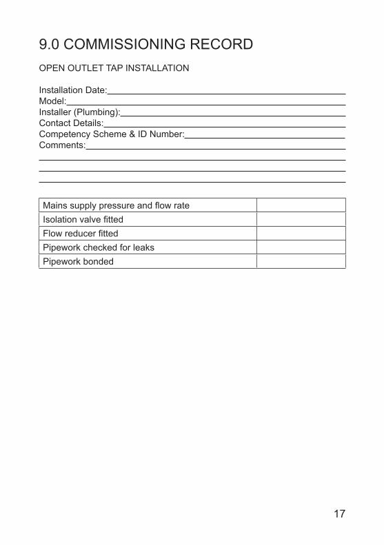
9.0 COMMISSIONING RECORDOPEN OUTLET TAP INSTALLATION
Installation Date: Model: Installer (Plumbing): Contact Details: Competency Scheme & ID Number: Comments:
Mains supply pressure and flow rateIsolation valve fittedFlow reducer fittedPipework checked for leaksPipework bonded
18
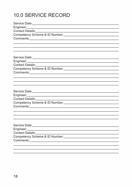
10.0 SERVICE RECORDService Date: Engineer: Contact Details: Competency Scheme & ID Number: Comments:
Service Date: Engineer: Contact Details: Competency Scheme & ID Number: Comments:
Service Date: Engineer: Contact Details: Competency Scheme & ID Number: Comments:
Service Date: Engineer: Contact Details: Competency Scheme & ID Number: Comments:

19
Service Date: Engineer: Contact Details: Competency Scheme & ID Number: Comments:
Service Date: Engineer: Contact Details: Competency Scheme & ID Number: Comments:
Service Date: Engineer: Contact Details: Competency Scheme & ID Number: Comments:
Service Date: Engineer: Contact Details: Competency Scheme & ID Number: Comments:

36006093 issue 01
Heatrae Sadia Heating Hurricane Way Norwich NR6 6EAwww.heatraesadia.com
Service: 0844 8711535Service Fax: 0844 8711528E-mail: heatraesadiaservice
@heateam.co.uk
11.0 SPARES STOCKISTSFor the fast and efficient supply of spares please contact the stockists listed below.
Advanced Water Company Ltd.Unit D5 Enterprise wayVale park, EveshamWorcs, WR11 1GSTel: 01386 760066Fax: 01386 760077
Electric Water Heating Co. 2 Horsecroft Place, PinnaclesHarlow, Essex, CM19 5BTTel: 0845 0553811E-Mail: [email protected]
SPDUnits 9 & 10 Hexagon Business CentreSpringfield Road, HayesMiddlesex, UB40 0TYTel: 020 8606 3567
Parts CenterTel: 0845 2709800www.partscenter.co.uk
Newey & EyreSpecialist Products DivisionPlease contact your local branch
UK Spares Ltd.Tower Lane, WarmleyBristol, BS30 8XTTel: 0117 961 6670
William Wilson Ltd.Unit 3A, 780 South StreetWhiteinch, Glasgow, G14 OSYTel: 0141 434 1530

![HRU ECO 4 - Heatrae Sadia · 2018. 2. 9. · 2.3. Technical data Description Symbol Unit HRU ECO 4 Apartment House DIMENSIONS AND WEIGHT Dimensions [HxWxD] — mm 848 x 730 x 479](https://img.dokumen.tips/doc/110x75/6116d2888378e277787241a2/hru-eco-4-heatrae-sadia-2018-2-9-23-technical-data-description-symbol-unit.jpg)