Embed Size (px)
DESCRIPTION
Some properties of Open Max Integartion layer
Citation preview

OpenMAX™ Integration Layer Application Programming
Interface Specification

OpenMAX - General Definition
• OpenMAX™ is a royalty-free, cross-platform API that provides comprehensive streaming media codec and application portability
• It enables accelerated multimedia components to be developed, integrated and programmed across multiple operating systems and silicon platforms
• The OpenMAX API will be shipped with processors to enable library and codec implementers to rapidly and effectively make use of the full acceleration potential of new silicon - regardless of the underlying hardware architecture
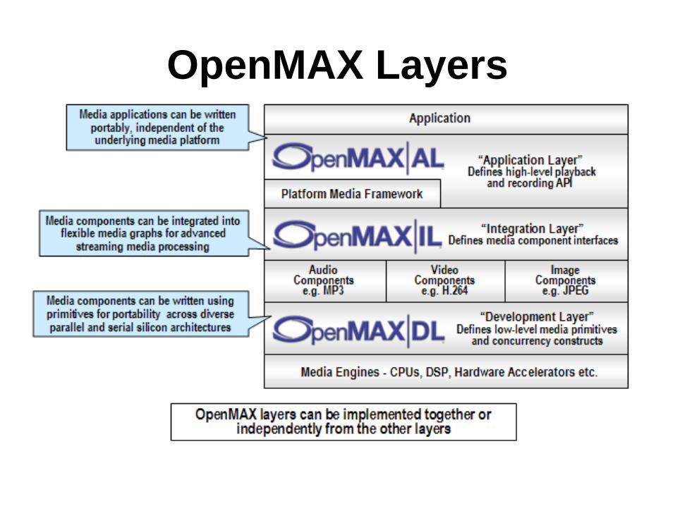
OpenMAX Layers

OpenMAX Application Layer
• The OpenMAX AL API defines a set of APIs providing a standardized interface between an application and multimedia middleware
• The AL provides application portability with regards to the multimedia interface
OpenMAX Integration Layer
• OpenMAX IL serves as a low-level interface for audio, video, and imaging codecs used in embedded and/or mobile devices
• It gives applications and media frameworks the ability to interface with multimedia codecs and supporting components (i.e. sources and sinks) in a unified manner
• The codecs themselves may be any combination of hardware or software and are completely transparent to the user. Without a standardized interface of this nature, codec vendors must write to proprietary or closed interfaces to integrate into mobile devices
OpenMAX Development Layer
• OpenMAX DL defines an API which contains a comprehensive set of audio, video and imaging functions that can be implemented and optimized on new processors by silicon vendors and then used by codec vendors to code a wide range of codec functionality
• It includes audio signal processing functions such as FFTs and filters, imaging processing primitives such as color space conversion and video processing primitives to enable the optimized implementation of codecs such as MPEG-4, H.264, MP3, AAC and JPEG

OpenMAX IL API Software Landscape
• The OpenMAX IL components are divided in three main domains: audio, video and imaging
• The other domain (timing info, bitstream) includes the mixed domain components like video/imaging processors

OpenMAX IL Core
• Used for dynamically loading and unloading components and for facilitating component communication
• Once loaded, the API allows the user to communicate directly with the component, which eliminates any overhead for high commands
• Similarly, the core allows a user to establish a communication tunnel between two components
• Once established, the core API is no longer used and communications flow directly between components

OpenMAX IL Components
• Components represent individual blocks of functionality
• Components can be sources, sinks, codecs, filters, splitters, mixers, or any other data operator
• Depending on the implementation, a component could possibly represent a piece of hardware, a software codec, another processor, or a combination thereof
• The individual parameters of a component can be set or retrieved through a set of associated data structures, enumerations, and interfaces
• The parameters include data relevant to the component’s operation (i.e., codec options) or the actual execution state of the component

OpenMAX IL Components cont..
• Buffer status, errors, and other time-sensitive data are relayed to the application via a set of callback functions. These are set via the normal parameter facilities and allow the API to expose more of the asynchronous nature of system architectures
• Data communication to and from a component is conducted through interfaces called ports
• Users may send data to components through input ports or receive data through output ports
• Similarly, a communication tunnel between two components can be established by connecting the output port of one component to a similarly formatted input port of another component

OpenMAX IL API System Components
• Source components - Components with a single output port
• Sink components - Components with a single input port • Host components - Components running entirely on the
host processor• Accelerator components - Components running on a
loosely coupled accelerator
Types of communication
• Non-tunneled communication defines a mechanism for exchanging data buffers between the IL client and a component
• Tunneled communicatiion defines a standard mechanism for components to exchange data buffers directly with each other in a standard way
• Proprietary communication describes a proprietary mechanism for direct data communications between two components and may be used as an alternative when a tunneling request is made, provided both components are capable of doing so
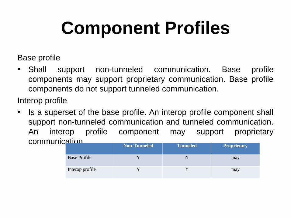
Component Profiles
Base profile • Shall support non-tunneled communication. Base profile
components may support proprietary communication. Base profile components do not support tunneled communication.
Interop profile • Is a superset of the base profile. An interop profile component shall
support non-tunneled communication and tunneled communication. An interop profile component may support proprietary communication.
Non-Tunneled Tunneled Proprietary
Base Profile Y N may
Interop profile Y Y may

Component States
•Loaded: alive without resources•Waiting for resources: deficient of resources and actively waiting for them to become available•Idle: has resources but not transferring buffers•Paused: has resources, transferring buffers, but not processing data•Executing: has resources, transferring buffers, and processing data• Invalid : shall stop, de-initialize, unload and reload the component
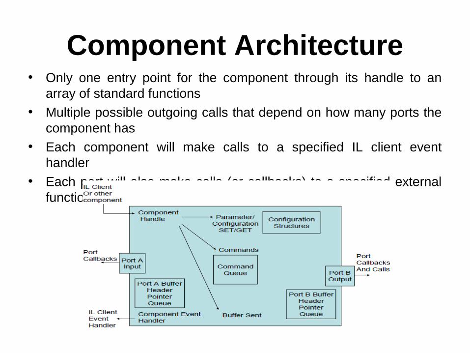
Component Architecture• Only one entry point for the component through its handle to an
array of standard functions• Multiple possible outgoing calls that depend on how many ports the
component has• Each component will make calls to a specified IL client event
handler• Each port will also make calls (or callbacks) to a specified external
function

Component Architecture cont..
• A queue for pointers to buffer headers is also associated with each port. These buffer headers point to the actual buffers
• The command function also has a queue for commands. All parameter or configuration calls are performed on a particular index and include a structure associated with that parameter or configuration
• A port must support callbacks to the IL client and, when part of an interop profile component, must support communication with ports on other components

Communication Behavior• Configuration of a component may be accomplished once the
handle to the component has been received from the OpenMAX core.
• Data communication calls with a component are non-blocking and are enabled once the number of ports has been configured
• Each port has been configured for a specific data format and the component has been put in the appropriate state
• Data communication is specific to a port of the component. • Input ports are always called from the IL client with
OMX_EmptyThisBuffer• Output ports are always called from the IL client with
OMX_FillThisBuffer • In an in-context implementation, callbacks to
OMX_EmptyBufferDone or OMX_FillBufferDone will be made before the return and vice-versa in an out-of-context implementation.
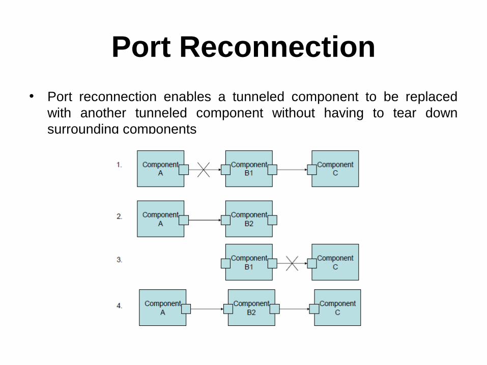
Port Reconnection
• Port reconnection enables a tunneled component to be replaced with another tunneled component without having to tear down surrounding components
Port Reconnection cont..
• Component B1 is to be replaced with component B2• To do this, the component A output port and the
component B1 input port shall first be disabled with the port disable command
• Once all allocated buffers have returned to their rightful owner and freed, the component A output port may be connected to component B2
• The component B1 output port and the component C input port should similarly be given the port disable command. After all allocated buffers have returned to their owners and freed, the component C input port may be connected to the component B2 output port. Then all ports may be given the enable command
Port Reconnection cont..
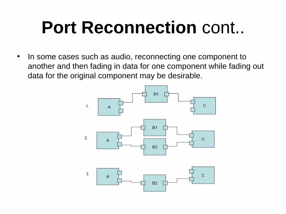
• In some cases such as audio, reconnecting one component to another and then fading in data for one component while fading out data for the original component may be desirable.

Port Reconnection cont..
• In step 1, component A sends data to component B1, which then sends the data on to component C. Components A and C both have an extra port that is disabled.
• In step 2, the IL client first establishes a tunnel between component A and B2, then establishes a tunnel between B2 and C, and then enables all ports in the two tunnels. Component C may be able to mix data from components B1 and B2 at various gains, assuming that these are audio components.
• In step 3, the ports connected to component B1 from components A and C are disabled, and component B1 resources may be de-allocated.

Queues and Flush
• A separate command queue enables the component to flush buffers that have not been processed and return these buffers to the IL client when using non-tunneled communication or to the tunneled port when using tunneled communication

Queues and Flush
• Assume that the component has an output port that is using buffers allocated by the IL client.
• In this example, the client sends a series of five buffers to the component before sending the flush command.
• Upon processing the flush command, the component returns each unprocessed buffer in the original order, and finally triggers its event handler to notify the IL client.
• Two buffers were already processed before the flush command got processed. The component returns the remaining three buffers unfilled and generates an event.
• The IL client should wait for the event before attempting to de-initialize the component.
Marking Buffers
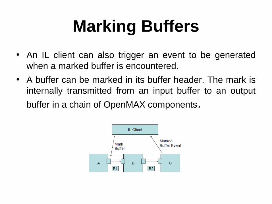
• An IL client can also trigger an event to be generated when a marked buffer is encountered.
• A buffer can be marked in its buffer header. The mark is internally transmitted from an input buffer to an output
buffer in a chain of OpenMAX components.

Marking Buffers cont..
• The mark enables a component to send an event to the IL client when the marked buffer is encountered.
• The IL client sends a command to mark a buffer. The next buffer sent from the output port of the component is marked B1. Component B processes the B1 buffer and provides the results in buffer B2 along with the mark.
• When component C receives the marked buffer B2 through its input port, the component does not trigger its event handler until it has processed the buffer.

Events and Callbacks
• Error events are enumerated and can occur at any time
• Command complete notification events are triggered upon successful execution of a command
• Marked buffer events are triggered upon detection of a marked buffer by a component
• A port settings changed notification event is generated when the component changes its port settings
• A buffer flag event is triggered when an end of stream is encountered
• A resources acquired event is generated when a component gets resources that it has been waiting for
• Ports make buffer handling callbacks upon availability of a buffer or to indicate that a buffer is needed.

Buffer Payload• The port configuration is used to determine and define the
format of the data to be transferred on a component port, but the configuration does not define how that data exists in the buffer.
• Three cases describe how a buffer can be filled with data• In all cases, the range and location of valid data in a buffer is
defined by the pBuffer, nOffset, and nFilledLength parameters of the buffer header
• The pBuffer parameter points to the start of valid data in the buffer
• The nOffset parameter indicates the number of bytes between the start of the buffer and the start of valid data
• The nFilledLength parameter specifies the number of contiguous bytes of valid data in the buffer
• The valid data in the buffer is therefore located in the range pBuffer +nOffset to pBuffer + nOffset + nFilledLength
Buffer Payload cont..
• The following cases are representative of compressed data in a buffer that is transferred into or out of a component when decoding or encoding
• In all cases, the buffer just provides a transport mechanism for the data with no particular requirement on the content
• The requirement for the content is defined by the port configuration parameters
• The shaded portion of the buffer represents data and the white portion denotes no data
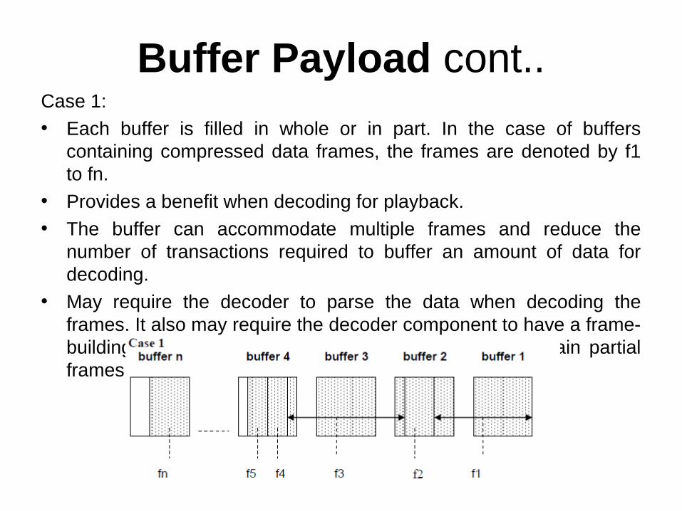
Buffer Payload cont..Case 1: • Each buffer is filled in whole or in part. In the case of buffers
containing compressed data frames, the frames are denoted by f1 to fn.
• Provides a benefit when decoding for playback. • The buffer can accommodate multiple frames and reduce the
number of transactions required to buffer an amount of data for decoding.
• May require the decoder to parse the data when decoding the frames. It also may require the decoder component to have a frame-building buffer in which to put the parsed data or maintain partial frames that would be completed with the next buffer.

Buffer Payload cont..
Case 2: • Each buffer is filled with only complete frames of compressed data. • Case 2 differs from case 1 because it requires the compressed data
to be parsed first so that only complete frames are put in the buffers. • May also require the decoder component to parse the data for
decoding. This case may not require the extra working buffer for parsing frames required in case 1.

Buffer Payload cont..
Case 3: • Each buffer is filled with only one frame of compressed data. The
benefit in case 3 is that a decoding component does not have to parse the data.
• Parsing would be required at the source component. However, this method creates a bottleneck in data transfer. Data transfer would be limited to one frame per transfer.
• Depending on the implementation, one transaction per frame could have a greater impact on performance than parsing frames from a buffer.

Buffer Flags and Timestamps• Buffer flags associate certain properties (e.g., the end of a
data stream) with the data contained in a buffer. • A buffer timestamp associates a presentation time in
microseconds with the data in the buffer used to time the rendering of that data.
• Once a timestamp is associated with a buffer, no component should alter the timestamp for rate control or synchronization, which are implemented in the clock component.
• Buffer metadata (i.e., flags and timestamps) applies to the first new logical unit in the buffer. Thus, given the presence of multiple logical units in a buffer, the metadata applies to the logical unit whose starting boundary occurs in the buffer.
• Unless otherwise stated (e.g., in a flag definition), a component that receives a logical input unit marked with a flag or timestamp shall copy that metadata to all logical output units that the input contributes to.

Synchronization
• Synchronization is enabled by the use of synchronization (sync) ports on a clock component.
• These ports and the clock component are defined within the “other” domain and operate with the same protocols and calls that regulate data ports.
• The clock component maintains a media clock that tracks the position in the media stream based on audio and video reference clocks.

Synchronization cont..
• The clock component transmits buffers containing time information (denoted by a media time update and containing the media clock’s current position, scale, and state) to client components via sync ports.
• A client component may time the execution of an operation (e.g., the presentation of a video frame) to a timestamp by requesting that the clock component send that timestamp when it matches the media clock. In this case, the client component executes the operation when it receives the fulfillment of the request over its sync port.

Rate Control• The clock component also implements all rate control by
exposing a set of configurations for controlling its media clock. • The IL client may change the scale factor of the media clock
(effectively changing the rate and direction that the media clock advances) to implement play, fast forward, rewind, pause, and slow motion trick modes.
• The IL client may also start and stop the clock by using these configurations to change the state of the media clock.
• The clock component makes all of its client components aware of a change to the media clock scale and state by sending a media time update with the new scale or state on all sync ports.
• Although a component may not alter a buffer timestamp in reaction to a scale change, a component may alter its processing accordingly. For instance, an audio component might scale and pitch correct audio during trick modes or cease transmitting output entirely.
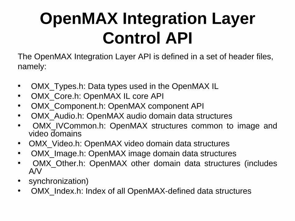
OpenMAX Integration Layer Control API
The OpenMAX Integration Layer API is defined in a set of header files, namely:
• OMX_Types.h: Data types used in the OpenMAX IL• OMX_Core.h: OpenMAX IL core API• OMX_Component.h: OpenMAX component API• OMX_Audio.h: OpenMAX audio domain data structures• OMX_IVCommon.h: OpenMAX structures common to image and
video domains• OMX_Video.h: OpenMAX video domain data structures• OMX_Image.h: OpenMAX image domain data structures• OMX_Other.h: OpenMAX other domain data structures (includes
A/V• synchronization)• OMX_Index.h: Index of all OpenMAX-defined data structures

OpenMAX Types
EnumerationsFive 32-bit integer enumerations are defined in
OMX_Core.h:• OMX_ERRORTYPE defines the standard OpenMAX
errors that all functions defined in the OpenMAX IL API return.
• OMX_COMMANDTYPE includes the possible commands that an IL client can send to an OpenMAX component
• OMX_EVENTTYPE includes events that can be generated inside an OpenMAX component and that are passed to the IL client through a callback function
• OMX_BUFFERSUPPLIERTYPE includes all the possibilities for the buffer supplier in the case of tunneled ports.
• OMX_STATETYPE, illustrates the transitions among states.

OMX_ERRORTYPE• These errors should cover most of the common failure cases. • Vendors are free to add additional error messages of their own as
long as they follow these rules:• Vendor error messages shall be in the range of 0x90000000 to
0x9000FFFF.• Vendor error messages shall be defined in a header file provided
with the component. No error messages are allowed that are not defined.
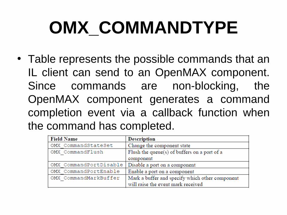
OMX_COMMANDTYPE
• Table represents the possible commands that an IL client can send to an OpenMAX component. Since commands are non-blocking, the OpenMAX component generates a command completion event via a callback function when the command has completed.

OMX_EVENTTYPE
• The OMX_EVENTTYPE enumeration shown in Table includes the event types that an OpenMAX component can generate.
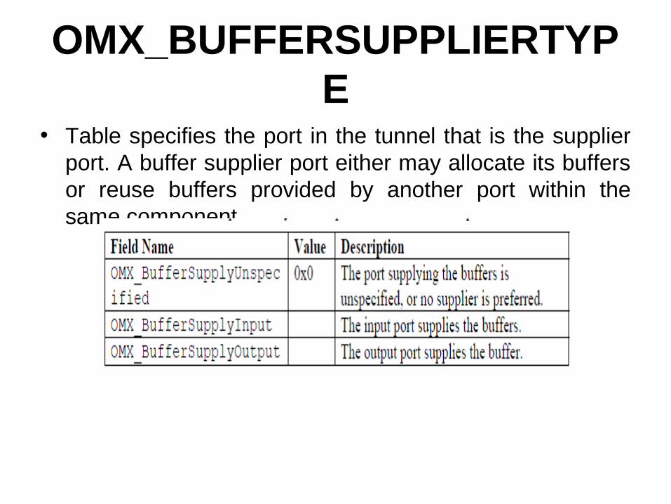
OMX_BUFFERSUPPLIERTYPE
• Table specifies the port in the tunnel that is the supplier port. A buffer supplier port either may allocate its buffers or reuse buffers provided by another port within the same component.

OMX_STATETYPE
• Fig. illustrates the transitions among states that occur as a consequence of the IL client calling OMX_SendCommand(OMX_StateSet, <state>), where the new state for the component is passed as a parameter. A transition name surrounded by curly braces indicates that the transition is not triggered by a command sent by the IL client but is a consequence of internal component events.

OpenMAX Component State Transitions
• An IL client commands a component to change states via the OMX_SendCommand function using the OMX_CommandStateSet command.

Structures
• This section discusses the data structures defined in the OpenMAX core.
• The first two fields of each OpenMAX data structure denote the size of the structure and the version of type OMX_VERSIONTYPE.
• The entity that allocates an OpenMAX structure is responsible for filling in these two values.

OMX_COMPONENTREGISTERTYPE
• The OMX_COMPONENTREGISTERTYPE structure is used in the case of static linking of components to the core. The core optionally uses it to load the component and run the specific component initialization functions.
• OMX_COMPONENTREGISTERTYPE is defined as follows.
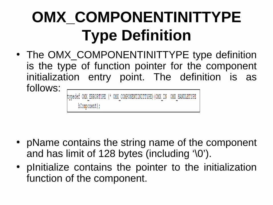
OMX_COMPONENTINITTYPE Type Definition
• The OMX_COMPONENTINITTYPE type definition is the type of function pointer for the component initialization entry point. The definition is as follows:
• pName contains the string name of the component and has limit of 128 bytes (including ‘\0’).
• pInitialize contains the pointer to the initialization function of the component.

OMX_VERSIONTYPE
• The OMX_VERSIONTYPE type indicates the version of a component or structure.
• Each structure uses an OMX_VERSIONTYPE field to indicate the OpenMAX specification version under which the structure is defined. For OpenMAX IL version 1.0, the specification version is 1.0.0.0.
• The component structure also includes an OMX_VERSIONTYPE field to indicate a vendor-specific component version.

OMX_PRIORITYMGMTTYPE
• The OMX_PRIORITYMGMTTYPE type describes the priority assigned to a set of components.
• A component group identifies a set of co-dependent components associated with the same feature. All components in the same group share the same group ID and priority.
• If one component in a group loses resources and stops running, the entire feature they collectively contribute to is lost. In this case, all of the other components in the same group shall transition to OMX_StateLoaded. A component that is the only one with a certain nGroupID acts atomically.
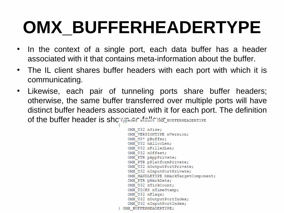
OMX_BUFFERHEADERTYPE• In the context of a single port, each data buffer has a header
associated with it that contains meta-information about the buffer. • The IL client shares buffer headers with each port with which it is
communicating. • Likewise, each pair of tunneling ports share buffer headers;
otherwise, the same buffer transferred over multiple ports will have distinct buffer headers associated with it for each port. The definition of the buffer header is shown as follows.

OMX_CALLBACKTYPEThe OpenMAX IL includes a callback mechanism that allows a
component to communicate the following with the IL client:• An asynchronous command triggered by the IL client has completed
successfully or failed and generated an error. Commands include those sent by OMX_SendCommand and those implied by IL client calls to EmptyThisBuffer or FillThisBuffer.
• An error unassociated with a command triggered by the IL client has occurred. For example, the component has suffered an unrecoverable error and is transitioning to the OMX_StateInvalid state.
To accomplish a callback, the OpenMAX IL has three callback functions
defined: • A generic event handler and two callbacks related to the dataflow
(EmptyBufferDone and FillBufferDone).• The IL client is responsible for filling in an OMX_CALLBACKTYPE
structure with its callback entry points and passing the structure to the OpenMAX core at initialization (init) time, usually in the OMX_GetHandle function.

OMX_CALLBACKTYPE cont..

OpenMAX Core Methods/Macros
• The OpenMAX core implements the main interface for an IL client that wants to use OpenMAX components.
• For efficiency, OpenMAX IL defines a set of OpenMAX core macros that map on one-to-one basis to most OpenMAX component methods.
• Some macros and methods recommend that the function return within either five milliseconds or 20 milliseconds, depending on the function.
• The 5-millisecond timeout was deemed by the standards body to be a reasonable response time for commands that may not require buffer processing.
• The standards body identified the 20-millisecond timeout to be a reasonable response time for commands that may require buffer processing to be completed; the assumption here is that the longest buffer processing would be less than 30 milliseconds, which corresponds to 30-frames per second video.
• These timeouts are intended primarily to enable component integrators to get a good idea of component response latency via conformance testing.

OpenMAX Core Macros
The macros include the following:• Get component information (version, capabilities).• Set/Get component parameters at init time.• Set/Get component parameters at run time.• Allocate/De-allocate buffers.• Send a buffer full of data to an OpenMAX component
port.• Send an empty buffer to an OpenMAX component
port.• Send commands to a component.• Get the actual state of the component.• Get references to OpenMAX component-proprietary
parameters.

OpenMAX Core Methods
The OpenMAX Core also implements methods for
the following:• Initializing/de-initializing the whole OpenMAX
IL Core• Getting an OpenMAX component handle• Releasing an OpenMAX component handle• Detecting all OpenMAX components
available on the platform at run time• Setting up data tunnels among OpenMAX
components

Error Codes
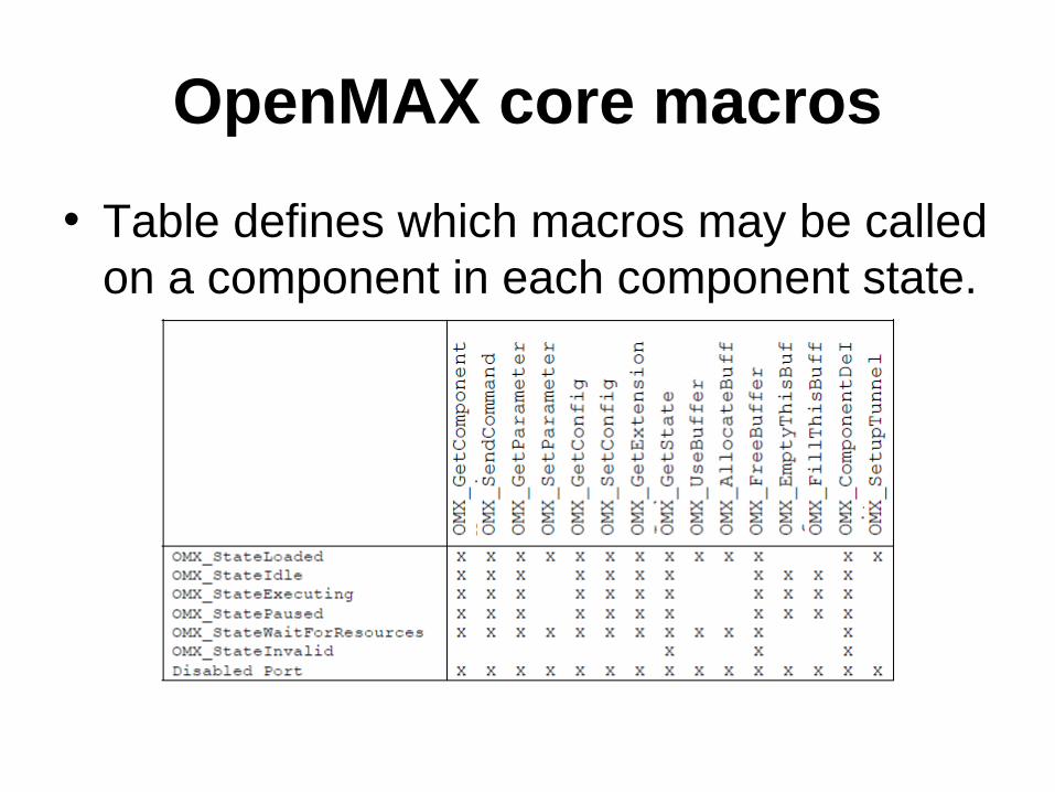
OpenMAX core macros
• Table defines which macros may be called on a component in each component state.

OMX_GetComponentVersion• The GetComponentVersion macro will query the component and returns information about
it. • This is a blocking call. • The component should return from this call within five msec.• The macro is defined as follows.#define OMX_GetComponentVersion (hComponent,pComponentName,pComponentVersion,pSpecVersion,pComponentUUID )((OMX_COMPONENTTYPE*)hComponent)->GetComponentVersion( \hComponent, \pComponentName, \pComponentVersion, \pSpecVersion, \pComponentUUID)

Sample Code Showing Calling Sequence

OpenMAX core macros cont..
• OMX_SendCommand - Will invoke a command on the component• OMX_CommandStateSet - IL client calls this command to request
that the component transition into the state given• OMX_CommandFlush - IL client calls this command to flush one or
more component ports• OMX_CommandPortDisable - Disables a port• OMX_CommandPortEnable - Enables a port• OMX_CommandMarkBuffer - Instructs the given port to mark a
buffer• OMX_GetParameter - Will get a parameter setting from a
component• OMX_SetParameter - Will send a parameter structure to a
component• OMX_GetConfig - Will get a configuration structure from a
component• OMX_SetConfig - Will set a component configuration value

OpenMAX core macros cont..• OMX_GetExtensionIndex - Will invoke a component to translate
from a standardized OpenMAX or vendor-specific extension string for a configuration or a parameter into an OpenMAX structure index
• OMX_GetState - Will invoke the component to get the current state of the component
• OMX_UseBuffer - Requests the component to use a buffer already allocated by the IL client or a buffer already supplied by a tunneled component
• OMX_AllocateBuffer - Will request that the component allocate a new buffer and buffer header
• OMX_FreeBuffer - Will release a buffer and buffer header from the component
• OMX_EmptyThisBuffer - Will send a filled buffer to an input port of a component
• OMX_FillThisBuffer - Will send an empty buffer to an output port of a component

Functions in the Openmax IL API
OMX_Init• The OMX_Init method initializes the OpenMAX core. • OMX_Init shall be the first call made into OpenMAX and
should be executed only one time without an intervening OMX_Deinit call.
• If OMX_Init is called twice, OMX_ErrorNone is returned but the init request is ignored. The core should return from this call within 20 msec.
The usage of OMX_Init() is as follows.• OMX_API OMX_ERRORTYPE OMX_APIENTRY OMX_Init()• If the command successfully executes, the return code will be
OMX_ErrorNone.• Otherwise, the appropriate OpenMAX error will be returned. • The OpenMAX core functions are ready to be used when this
function returns successfully.

Sample Code Showing Calling Sequence
Functions in the Openmax IL API
• OMX_Deinit – It De-initialises the OpenMax Core.• OMX_ComponentNameEnum – Will enumerate through all the
names of recognized components in the system to detect all the components in the system run-time
• OMX_GetHandle – Will locate the component specified by the component name given, load that component into memory, and validate it
• OMX_FreeHandle – Will free a handle allocated by the OMX_GetHandle
• method. • OMX_SetupTunnel – Sets up tunneled communication between an
output• port and an input port. This API is used only in interop profile and in
base profile this API is nullified.

Calling Sequences
• This section describes how the IL client, the OpenMAX core, and the components dynamically interact in a few meaningful use cases, namely initialization, de-initialization, data flow, data tunneling setup, and data flow in the case of data tunneling and dynamic port reconfiguration.
• The interaction between the core, the components, and the possible implementation of a resource manager is also described.

Component Initialization

Example of Data Tunneling Among OpenMAX Components

Tunnel Setup
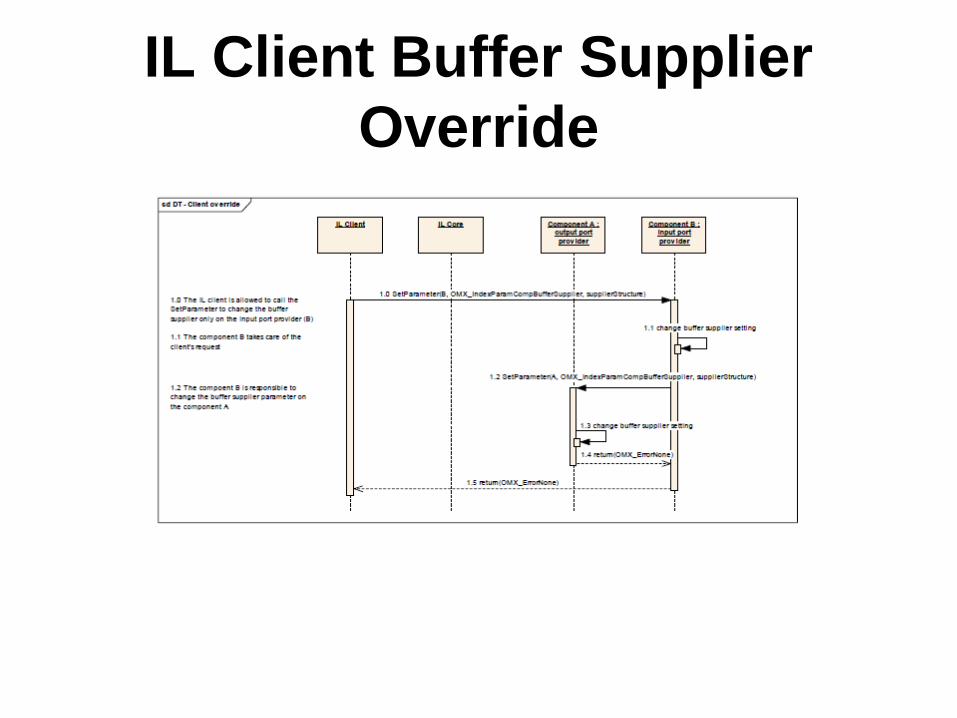
IL Client Buffer Supplier Override

Tunneling Example

State Transition to Idle in the Case of Tunneled Components

Data Flow Between Non-tunneled Components
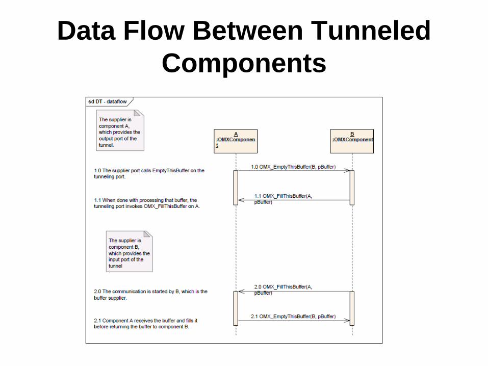
Data Flow Between Tunneled Components

Data Flow with Proprietary Communication Between
Components

De-initialization of Non-tunneled Components

De-initialization of Tunneled Components

Disablement and Enablement of Tunneled Ports

Disablement and Enablement of Non-tunneled Ports

Dynamic Port Reconfiguration
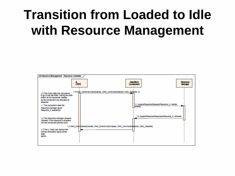
Transition from Loaded to Idle with Resource Management

Busy Resource Management

State Change from Loaded to WaitForResources
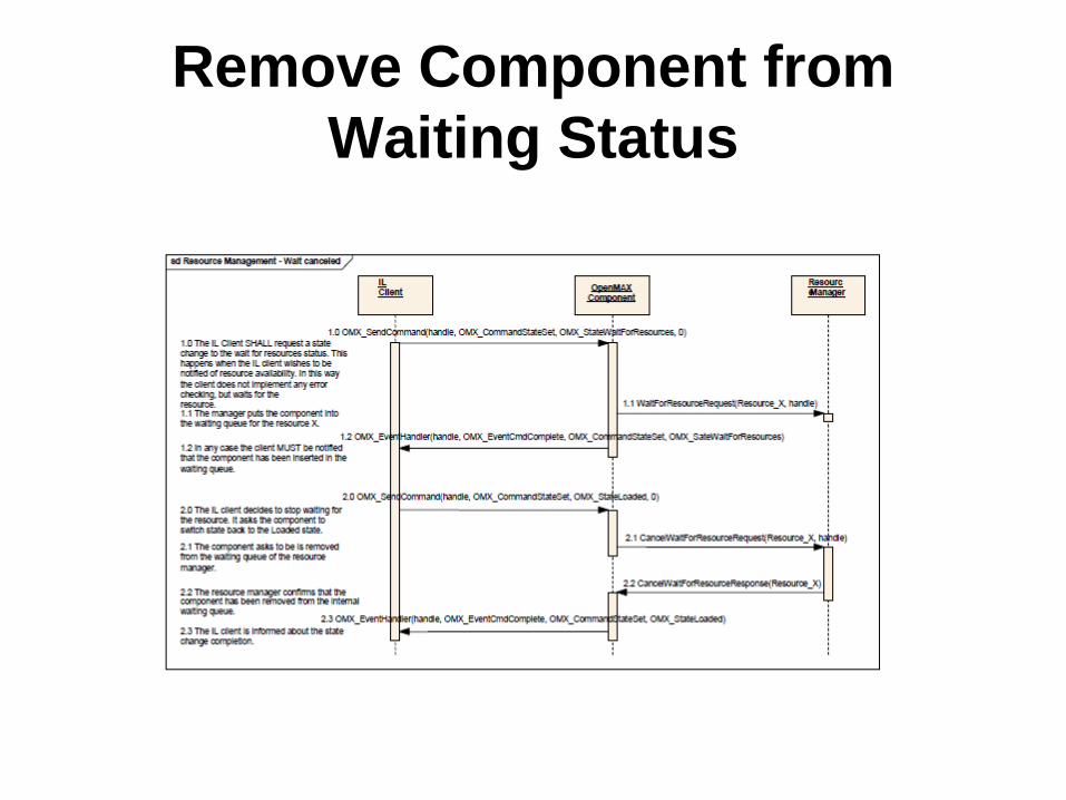
Remove Component from Waiting Status

Audio-Video File Playback Example Use Case
Audio-Video File Playback Example Use Case
• Examine the playback of a file containing synchronized audio and video
• This example assumes that each audio or video frame has a presentation timestamp associated with it.
• In this construction, a file reader/demultiplexing component feeds compressed audio and video streams to a pair of decoders.
• The decoders send uncompressed data to a pair of renderers, which deliver the data to hardware.
• The renderers coordinate with the clock component to implement smooth synchronized audio-video delivery.
• The renderers and audio decoder are clients of the clock component (connected on their respective clock ports) so they may watch for scale changes.
• The video renderer also uses the clock component to time delivery of video frames via media time requests.
Audio-Video File Playback Example Use Case cont..
• The audio and video renderers act as the audio and video reference clocks, each sending their reference times to the clock component as they deliver data.
• In this example, the IL client uses the audio renderer as the reference clock at any time audio data is being delivered during normal playback. Thus, the IL client does not need to use the clock component to coordinate the delivery of audio data.
• It simply feeds new data to the audio device whenever it can, provided that the current scale allows it.
• When the audio device is presenting an audio buffer, the audio renderer emits the timestamp of
• that buffer as a reference.• The video renderer, however, shall coordinate with the clock
component when delivering video frames.

Audio-Video File Playback Example Use Case cont..
For each frame that the renderer shall deliver at a particular timestamp, the following occurs:• 1. The renderer submits a media time request, referencing the
frame data in the private pointer and specifying fulfillment slightly earlier that the timestamp.
• 2. The clock component fulfills the request when it becomes current via a media time update to the renderer that references the original timestamp and includes the private pointer.
• 3. The renderer receives the media time update, de-references the private pointer to obtain the frame data, and delivers the frame. The renderer uses an implementation specific mechanism to wait the remainder of the time until the timestamp before delivery (e.g., schedules a hardware flip with the video driver).

Audio-Video File Playback Example Use Case cont..
• The IL client controls the clock component via specialized configurations to start and stop the media clock.
• To implement trick modes, the IL client sets the scale factor configuration. When the clock component applies the scale to the calculation of media time, it sends a media time update with the scale change to all of its clients.
• The client components react to that scale change appropriately. When the scale is 0 (i.e., the media clock is paused), the audio renderer silences audio and ceases sending data.
• Furthermore, in this example, the audio decoder might elect to ignore input during non- 1X playback.
• If audio is effectively silenced during trick modes, the IL client may switch the active reference clock from the audio reference to the video reference.
• Finally, the IL client may query the current media time from the clock component to, for instance, update the user interface such as through a progress bar.

Q&A